Host Connectrac Assembly Instruction (.pdf 1 MB) - Coalesse
Host Connectrac Assembly Instruction (.pdf 1 MB) - Coalesse
Host Connectrac Assembly Instruction (.pdf 1 MB) - Coalesse

Create successful ePaper yourself
Turn your PDF publications into a flip-book with our unique Google optimized e-Paper software.
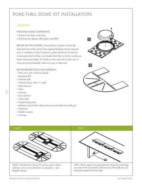
POKE-THRU DOME KIT INSTALLATION<br />
CONTENTS:<br />
POKE-THRU DOME COMPONENTS:<br />
1. Dome Cover, Base, and screw<br />
2. End Transition Ramps, ABS plastic and MDF<br />
1<br />
BEFORE GETTING STARTED: Concrete floor surfaces must be flat,<br />
level and structurally sound. Floor topping/leveling may be required<br />
prior to installation of the <strong>Connectrac</strong> system. Aluminum <strong>Connectrac</strong><br />
components which will be cut to length should be cut with a non-ferrous<br />
metal-cutting saw blade. This blade can be used with a miter saw or<br />
chop saw (recommended), radial arm saw, or table saw.<br />
2<br />
III.21<br />
RECOMMENDED TOOLS AND MATERIALS:<br />
+ Miter saw with non-ferrous blade<br />
+ Standard drill<br />
+ Hammer drill<br />
+ Hand bit driver with ¼” socket<br />
+ Tape measure<br />
+ Pliers<br />
+ Hammer<br />
+ Dry wall saw<br />
+ Utility knife<br />
+ Carpet laying tools<br />
+ Adhesive (Liquid Nails, Heavy Duty, recommended) and caulk gun<br />
+ Chalk line<br />
+ Builder’s square<br />
+ Fish tape<br />
NOTE STEP 1<br />
NOTE: The Poke-Thru Dome Kit can be used to direct<br />
cabling in one or two directions as necessary – see<br />
diagram above.<br />
ONE: Mark carpet to accept poke-thru dome kit, and along<br />
one side of the <strong>Connectrac</strong> bottom track with chalk line. Cut<br />
and peel carpet from floor slab.<br />
INSTALLATION INSTRUCTIONS 1-877-480-5637
POKE-THRU DOME KIT INSTALLATION<br />
STEP 2 STEP 3<br />
TWO: Apply construction adhesive to underside of each<br />
depression on either side of dome cover. Sit assembled dome<br />
cover over poke-thru device and position to allow cabling to<br />
easily pass through openings into <strong>Connectrac</strong> channel.<br />
THREE: Saw bottom track, top cap, and side ramps to<br />
length needed to reach table base. Trim side ramps around<br />
contour of table base if needed.<br />
STEP 4 STEP 5<br />
III.22<br />
FOUR: Install <strong>Connectrac</strong> wireway per installation<br />
instructions.<br />
FIVE: Unscrew and remove dome cover lid. Connect<br />
power infeed conduit, and voice/data cables from table<br />
to poke-thru device.<br />
STEP 6 STEP 7<br />
SIX: Install carpet, trimming along edge of base track<br />
and ring of dome base. Adhere carpet to side ramps<br />
and dome base.<br />
SEVEN: Snap top cap into bottom track and reattach dome.<br />
WWW.CONNECTRAC.COM<br />
POKE-THRU DOME KIT
Proudly made in the USA<br />
For more product information visit connectrac.com,<br />
call us at 877-480 - 5637 or email us at info@connectrac.com<br />
ADA COMPLIANT - U.L. TESTED AND LISTED © 2011 STRONG PRODUCTS GROUP, LTD.<br />
<strong>Connectrac</strong> systems are protected by US Patent Nos. 6,844,493 and 6,566,598; others pending.<br />
REV.11/2012