Read/Download - SKB
Read/Download - SKB
Read/Download - SKB

You also want an ePaper? Increase the reach of your titles
YUMPU automatically turns print PDFs into web optimized ePapers that Google loves.
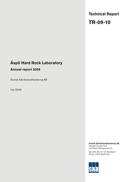
Technical Report<br />
TR-09-10<br />
Äspö Hard Rock Laboratory<br />
Annual report 2008<br />
Svensk Kärnbränslehantering AB<br />
July 2009<br />
Svensk Kärnbränslehantering AB<br />
Swedish Nuclear Fuel<br />
and Waste Management Co<br />
Box 250, SE-101 24 Stockholm<br />
Phone +46 8 459 84 00
Tänd ett lager:<br />
P, R eller TR.<br />
Äspö Hard Rock Laboratory<br />
Annual report 2008<br />
Svensk Kärnbränslehantering AB<br />
July 2009<br />
A pdf version of this document can be downloaded from www.skb.se.
Abstract<br />
The Äspö Hard Rock Laboratory (HRL) is an important part of <strong>SKB</strong>’s work with the design and<br />
construction of a deep geological repository for the final disposal of spent nuclear fuel. Äspö HRL<br />
is located in the Simpevarp area in the municipality of Oskarshamn. One of the fundamental reasons<br />
behind <strong>SKB</strong>’s decision to construct an underground laboratory was to create opportunities for<br />
research, development and demonstration in a realistic and undisturbed rock environment down to<br />
repository depth. The underground part of the laboratory consists of a tunnel from the Simpevarp<br />
peninsula to the southern part of Äspö where the tunnel continues in a spiral down to a depth of<br />
460 m. Äspö HRL has been in operation since 1995 and considerable international interest has been<br />
shown in its research, as well as in the development and demonstration tasks. A summary of the<br />
work performed at Äspö HRL during 2008 is given below.<br />
Geoscience<br />
Geoscientific research is a basic activity at Äspö HRL. The aim of the current studies is to develop<br />
geoscientific models of the Äspö HRL and increase the understanding of the rock mass properties<br />
as well as knowledge of applicable methods of measurement. A main task within the geoscientific<br />
field is the development of the Äspö Site Descriptive Model (SDM) integrating information from the<br />
different fields. The main activities in the geoscientific fields have been: (1) Geology – completion<br />
of the feasibility study concerning geological mapping techniques and mapping of rock surfaces<br />
in the new tunnel, (2) Hydrogeology – monitoring and storage of data in the computerised Hydro<br />
Monitoring System, (3) Geochemistry – sampling of groundwater in the yearly campaign and for<br />
specific experiments and (4) Rock Mechanics – field tests to evaluate the counterforce needed to<br />
prevent thermally-induced spalling in deposition holes.<br />
Natural barriers<br />
At Äspö HRL, experiments are performed under the conditions that are expected to prevail at<br />
repository depth. The experiments are related to the rock, its properties and in situ environmental<br />
conditions. The aim is to provide information about the long-term function of natural and repository<br />
barriers. Experiments are performed to develop and test methods and models for the description<br />
of groundwater flow, radionuclide migration, and chemical conditions at repository depth. The<br />
programme includes projects which aim to determine parameter values that are required as input to<br />
the conceptual and numerical models.<br />
A programme has been defined for tracer tests at different experimental scales, the so-called Tracer<br />
Retention Understanding Experiments (True). The overall objectives of the experiments are to gain<br />
a better understanding of the processes which govern the retention of radionuclides transported in<br />
crystalline rock and to increase the credibility of models used for radionuclide transport calculations.<br />
During 2008, work has been performed in the projects: True Block Scale Continuation and True-1<br />
Continuation (writing of papers to scientific journals) and True-1 Completion (meeting to plan the<br />
coming analyses of material from the over-coring of two boreholes at the True-1 site performed in<br />
2007).<br />
The Long Term Sorption Diffusion Experiment complements the diffusion and sorption experiments<br />
performed in the laboratory, and is a natural extension of the True-experiments. The in situ sorption<br />
diffusion experiment was started in September 2006 and after injection of epoxy resin the over-coring<br />
was successful in the beginning of May 2007. To allow determination of sorption and penetration<br />
profiles of the different tracers used in the experiment several sample preparation methods and analysis<br />
techniques have been necessary to adopt. During 2008 analyses were performed on sample cores<br />
drilled from the fracture surface on the core stub and from the matrix rock surrounding the test section.<br />
The Colloid Transport Project was initiated in 2008 and is a continuation of earlier colloid projects.<br />
The overall goal for the project is to answer the questions when colloid transport has to be taken<br />
into account in safety assessments. The project comprises field tests at the Grimsel test site in<br />
3
Switzerland and laboratory experiments to study colloid stability and mobility under different<br />
conditions. Modelling of colloid transport experiments in fractures with different length, filling and<br />
aperture was performed.<br />
Microorganisms interact with their surroundings and in some cases they greatly modify the<br />
characteristics of their environment. Several such interactions may have a significant influence on<br />
the function of a future repository for spent fuel, and are therefore studied in the Microbe Projects.<br />
In the microbe laboratory, located at the –450 m level in Äspö HRL, studies of microbial processes<br />
are on-going within several projects. Bio-mobilisation and bio-immobilisation of radionuclides are<br />
studied in Micomig, microbial effects on the chemical stability of deep groundwater environments in<br />
Micored and bio-corrosion in Biocor.<br />
The project Matrix Fluid Chemistry Continuation focuses on the small-scale micro-fractures in<br />
the rock matrix which facilitate the migration of matrix waters. Understanding of the migration<br />
of groundwater, and its changing chemistry, is important for repository performance. Data from<br />
hydraulic testing of fracture-free and fracture-containing borehole sections in the matrix borehole are<br />
available. Reporting of analyses of matrix pore water chemistry and the matrix borehole hydraulic<br />
studies is ongoing.<br />
The continuation of the project Padamot includes developments of analytical techniques for uranium<br />
series analyses applied on fracture mineral samples and focuses on the use of these analyses for<br />
determination of the redox conditions during glacial and postglacial time. Two laboratories have<br />
carried out uranium series analyses on samples taken from a drill core at Äspö. The results so far are<br />
very promising in that the samples seem to mirror the redox front, both mobilisation and deposition<br />
of uranium are shown.<br />
The basic idea behind the project Fe-oxides in Fractures is to examine Fe-oxide fracture linings, in<br />
order to explore suitable palaeo-indicators and their formation conditions. During 2008 the continuation<br />
phase of the project entitled: ’To establish the penetration depth of oxidising waters below<br />
ground surface’ has been finalised. A new analytical method to determine the penetration depth of<br />
oxidising waters using Fe-oxides has been used in the analyses of a drillcore from Laxemar. The<br />
results suggest that fractures of the upper 50 meters are currently experiencing episodes of oxidising<br />
conditions and that oxidising waters can penetrate down to a depth of approximately 90 meters<br />
without glacial influence.<br />
The Single Well Injection Withdrawal (Swiw) Test with Synthetic Groundwater constitutes a complement<br />
to the tests and studies performed on the processes governing retention of radionuclides in the<br />
rock, e.g. the True experiments. The feasibility study has been finalised and the True Block Scale<br />
Site is one of three candidate sites. The original plan for 2008 was to decide a test site for the project,<br />
but since the ongoing work at the new tunnel in the vicinity blocks the site until June 2009 the selection<br />
of a test site has been postponed.<br />
Important goals of the activities at Äspö HRL are the evaluation of the usefulness and reliability of<br />
different models and the development and testing of methods to determine parameter values required<br />
as input to the models. An important part of this work is performed in the Task Force on Modelling<br />
of Groundwater Flow and Transport of Solutes. Task 6 (performance assessment modelling using<br />
site characterisation data) initiated in 2001 has now been completed and modelling work is ongoing<br />
in Task 7 (long-term pumping test in Olkiluoto, Finland). Task 7 is also addressing the usage of<br />
Posiva Flow Log (PFL) data and issues related to open boreholes.<br />
Engineered barriers<br />
At Äspö HRL, an important goal is to demonstrate technology for and the function of important parts<br />
of the repository system. This implies translation of current scientific knowledge and state-of-the-art<br />
technology into engineering practice applicable in an operational repository. It is important that<br />
development, testing and demonstration of methods and procedures are conducted under realistic<br />
conditions and at an appropriate scale. A number of large-scale field experiments and supporting<br />
activities are therefore carried out at Äspö HRL. The experiments focus on different aspects of<br />
engineering technology and performance testing.<br />
4
The Prototype Repository is a demonstration of the integrated function of the repository and provides<br />
a full-scale reference for tests of predictive models concerning individual components as well as the<br />
complete repository system. The layout involves altogether six deposition holes, four in an inner<br />
section and two in an outer. The relative humidity, pore pressure, total pressure and temperature in<br />
different parts of the test area are monitored. Although the tunnel is drained, the pore pressure in the<br />
backfill in both sections is continuing to increase. During 2008, the work with the new tunnel near<br />
by the site has affected both the measured pressure and the water outflow from the tunnel.<br />
The Long Term Test of Buffer Material (Lot-experiment) aims at validating models and hypotheses<br />
concerning physical properties in a bentonite buffer material and of related processes regarding<br />
microbiology, radionuclide transport, copper corrosion and gas transport under conditions similar<br />
to those in a KBS-3 repository. Further analyses of the long-term test parcel (A2) have been made<br />
at different laboratories and the three remaining test parcels have been functioning without any<br />
disturbances during 2008.<br />
The objective of the project Alternative Buffer Materials is to study clay materials that in laboratory<br />
tests have shown to be conceivable buffer materials. Three test parcels with different combinations<br />
of clay materials are installed in boreholes at Äspö HRL. The parcels are heated carefully to increase<br />
the temperature in the buffer to 130°C. The heaters in two parcels were activated initially and the<br />
goal value was reached in the end of 2007. In the third parcel the buffer was fully saturated in<br />
August 2008 and the heaters were activated. In addition, analyses of different buffer materials have<br />
been performed.<br />
The Backfill and Plug Test is a test of the hydraulic and mechanical function of different backfill<br />
materials, emplacement methods and a full-scale plug. The inner part of the drift is backfilled with<br />
a mixture of bentonite and crushed rock and the outer part is filled with crushed rock. The wetting<br />
of the backfill started at the end of 1999 and the backfill was completely water saturated in 2003.<br />
Since then testing of flow to measure the hydraulic conductivity in different parts of the backfill and<br />
compressibility tests have been performed. Ongoing monitoring comprises measurements of water<br />
pressure, total pressure and leakage of water through the plug in the tunnel.<br />
The aim of the Canister Retrieval Test was to demonstrate readiness for recovering emplaced canisters<br />
even after the time when the surrounding bentonite buffer is fully saturated. The canister was<br />
successfully retrieved in 2006. The saturation phase had, at that time, been running for more than<br />
five years with continuous measurements of the wetting process, temperature, stresses and strains.<br />
During 2008, analyses of the retrieved buffer have progressed and are close to being finalised. The<br />
laboratory work has produced data of the mechanical strength, the swelling pressure, hydraulic<br />
conductivity and the chemical/mineralogical constitution.<br />
The Temperature Buffer Test aims at improving our current understanding of the thermo-hydromechanical<br />
behaviour of buffers with a temperature around and above 100°C during the water<br />
saturation transient. The experiment has generated data since the start in 2003 and the temperature in<br />
the buffer around the lower heater had, in the end of 2008, reached a value of 150°C. The evaluation<br />
of THM processes is made through analyses of sensors data and numerical modelling. In parallel,<br />
evaluation and numerical modelling are made of lab-scale mock-up tests performed by CEA in<br />
France. The previously planned gas injection test in the upper buffer will not be carried out since<br />
hydraulic tests revealed that the buffer around the sand-shield was not sufficiently tight.<br />
<strong>SKB</strong> and Posiva are co-operating on a programme for the KBS-3 Method with Horizontal<br />
Emplacement (KBS-3H). A continuation phase of the project is ongoing and the aim of the<br />
complementary studies is to develop KBS-3H to such a level that the decision of full scale testing<br />
can be made. During 2008 several tests have been performed at the –220 m level in Äspö HRL. The<br />
tests with the Megapacker, a grouting device, have been successful and the tests with the deposition<br />
equipment look very promising, however, improvements have to be made to make it more robust. In<br />
addition, preparations have been made for construction and testing of a compartment plug (steel plug).<br />
The aim of the Large Scale Gas Injection Test is to perform gas injection tests in a full-scale KBS-3<br />
deposition hole. The installation phase, including the deposition of canister and buffer, was finalised<br />
in 2005. Water is artificially supplied and the evolution of the saturation of the buffer is continuously<br />
monitored. The preliminary hydraulic and gas injection tests were completed in the first quarter of<br />
5
2008. Analysis of the hydraulic data indicates only minor or no changes of the buffer properties after<br />
the gas injection tests. In 2009 a second series of preliminary gas injection tests will be made as part<br />
of the ongoing hydration phase. A concerted effort has also been made for the quality assurance of<br />
experimental data during 2008.<br />
Although a repository will be located in rock mass of good quality with mostly relatively low fracturing,<br />
sealing by means of rock grouting will be necessary. The main goal of the project Sealing of Tunnel at<br />
Great Depth is to confirm that silica sol is a useful grout at the water pressures prevailing at repository<br />
level. To achieve this, the Tass-tunnel has been constructed at the –450 m level at Äspö HRL. The<br />
ex cavation of the Tass-tunnel started at the end of 2007 and has now reached its final length of<br />
80 meters. Grouting has been performed with ordinary grouting fans outside the tunnel contour and<br />
with holes drilled inside the contour. In the project it has been shown that it is possible to limit the<br />
inflow to a deposition tunnel to the required value with injection of silica sol both in fans outside and<br />
inside the tunnel contour.<br />
The objective of the project In situ Corrosion Testing of Miniature Canisters is to obtain a better<br />
understanding of the corrosion processes inside a failed canister. In Äspö HRL in situ experiments<br />
are performed with miniature copper canisters with cast iron inserts. The canisters will be exposed to<br />
both natural reducing groundwater and groundwater which has been conditioned by bentonite. In the<br />
beginning of 2007 all five canisters were installed in the boreholes and a report on the installation<br />
and results obtained until May 2008 has been prepared. The monitoring has continued and data<br />
relating to the chemical conditions, corrosion of the test specimens and dimensional changes are<br />
continuously collected and analysed.<br />
In the project Cleaning and Sealing of Investigation Boreholes the best available techniques are<br />
to be identified and demonstrated. In order to obtain data on the properties of the rock, boreholes<br />
are drilled during site investigations. These investigation boreholes must be cleaned and sealed,<br />
no later than at the closure of the repository. The work performed in 2008 has mainly included the<br />
characterisation of a number of investigation boreholes at Laxemar and Forsmark. The aim has been<br />
to select two boreholes that are representative and can be used as reference holes for further studies<br />
in the project.<br />
The Task Force on Engineered Barrier Systems addresses, in the first phase, two tasks: (1) THM<br />
processes and (2) gas migration in buffer material. However, at the end of 2006 it was decided to<br />
start a parallel Task Force that deals with geochemical processes in engineered barriers. During<br />
2008, two Task Force meetings have been held. In Benchmark 1 (laboratory tests) the modelling of<br />
THM processes and gas breakthrough is finalised. In Benchmark 2 (large scale field tests) the main<br />
work has been within modelling of the Canister retrieval test at Äspö HRL and the finalising of the<br />
modelling of the URL tests. Laboratory experiments and results from the experiment Long term<br />
test of buffer materials have been used as benchmarks for the performed geochemical modelling.<br />
The chemistry group has had two meetings were it was discussed how to adjust existing general<br />
geochemical modelling tools in order to successfully apply them to bentonite modelling.<br />
Äspö facility<br />
The Äspö facility comprises both the Äspö Hard Rock Laboratory and the Bentonite Laboratory.<br />
Important tasks of the Äspö facility are the administration, operation, and maintenance of instruments<br />
as well as development of investigation methods. The main goal of the operation of the<br />
facility is to provide a safe and environmentally sound facility for everybody working or visiting the<br />
Äspö HRL. The goal of an operational time of 98% for the underground laboratory was as earlier<br />
years exceeded. The Bentonite Laboratory has been in full operation during 2008, where different<br />
methods and techniques for installation of pellets and blocks in deposition tunnels and tests on<br />
piping and erosion of buffer and backfill material have been performed. The public relations and<br />
visitor services group is responsible for presenting information about <strong>SKB</strong> and its facilities. During<br />
the year 2008 <strong>SKB</strong> facilities and the site investigation activities in Oskarshamn and Forsmark were<br />
visited by about 24,000 visitors.<br />
6
Environmental research<br />
Äspö Environmental Research Foundation was founded in 1996 on the initiative of local and<br />
regional interested parties. The aim was to make the underground laboratory at Äspö and its<br />
resources available for national and international environmental research. The activities have since<br />
2003 been concentrated to the Äspö Research School. When the school’s activities were concluded<br />
as planned in 2008, the remaining and new research activities were transferred within the frame of<br />
a new co-operation, Nova Research and Development (Nova FoU). The aim is to support new and<br />
innovative research, where the extensive <strong>SKB</strong> data set from geological, hydrogeological, hydrogeochemical<br />
and ecological investigations can be used.<br />
International co-operation<br />
In addition to <strong>SKB</strong>, eight organisations from seven countries participated in the international<br />
co-operation at Äspö HRL during 2008. Six of them: Andra, BMWi, CRIEPI, JAEA, NWMO and<br />
Posiva together with <strong>SKB</strong> form the Äspö International Joint Committee which is responsible for the<br />
co-ordination of the experimental work arising from the international participation. The international<br />
organisations are participating in the experimental work at Äspö HRL as well as in the two Äspö<br />
Task Forces: (1) Task Force on Modelling of Groundwater Flow and Transport of Solutes and<br />
(2) Task Force on Engineered Barrier Systems.<br />
7
Sammanfattning<br />
Äspölaboratoriet i Simpevarp i Oskarshamns kommun är en viktig del i <strong>SKB</strong>:s arbete med utformning,<br />
byggande (och drift) av ett slutförvar för använt kärnbränsle. Ett av de grund läggande skälen till <strong>SKB</strong>:s<br />
beslut att anlägga ett underjordslaboratorium var att skapa förutsättningar för forskning, utveckling<br />
och demonstration i en realistisk och ostörd bergmiljö på förvarsdjup. Underjordslaboratoriet utgörs<br />
av en tunnel från Simpevarpshalvön till södra delen av Äspö där tunneln fortsätter i en spiral ner<br />
till 460 meters djup. Äspölaboratoriet har varit i drift sedan 1995 och verksamheten har väckt stort<br />
internationellt intresse. Här följer en sammanfattning av det arbete som bedrivits vid Äspölaboratoriet<br />
under 2008.<br />
Geovetenskap<br />
Forskning inom geovetenskap är en grundläggande del av arbetet vid Äspölaboratoriet. Det huvudsakliga<br />
målet med de pågående studierna är att utveckla geovetenskapliga modeller samt att öka<br />
förståelsen för bergmassans egenskaper och kunskapen om användbara mätmetoder. Den huvudsakliga<br />
uppgiften inom det geovetenskapliga området är utvecklingen av en platsbeskrivande modell för<br />
Äspö där information från olika ämnesområden integreras. De huvudsakliga aktiviteterna inom de<br />
olika områdena har varit: (1) Geologi – avslutat förstudien av geologiska karteringsmetoder och<br />
utfört kartering av bergytor i den nya tunneln, (2) Hydrogeologi – övervakning och lagring av data i<br />
det datoriserade hydromoniteringssystemet, (3) Geokemi – den årliga provtagningen av grundvatten<br />
samt provtagning för specifika experiment och (4) Bergmekanik – fältförsök för att utvärdera vilket<br />
mottryck som behövs för att förhindra termiskt inducerad spjälkning i deponeringshål.<br />
Naturliga barriärer<br />
I Äspölaboratoriet genomförs experimenten vid förhållanden som liknar de som förväntas råda<br />
på förvarsdjup. Experimenten kopplar till berget, dess egenskaper och in situ förhållanden. Målet<br />
med de pågående experimenten är att ge information om hur de naturliga och tekniska barriärerna<br />
fungerar i ett långtidsperspektiv. Ett viktigt syfte med verksamheten vid Äspölaboratoriet är att<br />
vidareutveckla och testa beräkningsmodeller för grundvattenströmning, radionuklidtransport och<br />
kemiska processer på förvarsnivå. I programmet ingår att bestämma värden på de parametrar som<br />
krävs som indata till konceptuella och numeriska modeller.<br />
Bergets förmåga att fördröja transport av spårämnen studeras i olika skalor i True-försöken. Syftet<br />
är att öka förståelsen för de processer som styr fördröjningen av radionuklider i kristallint berg<br />
samt att öka tillförlitligheten hos de modeller som används för beräkning av radionuklidtransport.<br />
Under 2008 har arbete skett inom delprojekten: ”True Block Scale Continuation” och ”True-1<br />
Continuation” (framtagning av artiklar för publicering i vetenskapliga tidskrifter) och ”True-1<br />
Completion” (möte för att planera de kommande analyserna av material från överborrningen av två<br />
borrhål vid True-1 som genomfördes under 2007).<br />
LTDE-försöket är ett komplement till de sorptions- och diffusionsförsök som genomförts i<br />
laboratorium och är också en utvidgning av de experiment som genomförts inom True-programmet.<br />
Sorptions- och diffusionsförsöket in situ startade i september 2006 och efter injicering av epoxi<br />
slutfördes överborrningen med lyckat resultat i början av maj 2007. För att kunna bestämma sorption<br />
och penetrationsprofiler för de olika spårämnen som användes i försöket har både provberedning<br />
och analysmetoder behövt anpassas. Analyser har under 2008 gjorts på provkärnor som borrats från<br />
sprickytan på borrkärnan och från den omkringliggande bergmatrisen.<br />
Kolloidtransportprojektet initierades under 2008 och är en fortsättning på tidigare genomförda<br />
kolloidprojekt. Målsättningen med projektet är att ge svar på frågor som rör hur kolloidtransport<br />
bör behandlas i kommande säkerhetsanalyser. I projektet ingår fältexperiment i Grimsellaboratoriet<br />
i Schweiz och laboratorieexperiment för att studera kolloiders stabilitet och rörlighet under olika<br />
förhållanden. Transportmodellering görs på genomförda experiment i sprickor med olika längd,<br />
fyllnadsmaterial och sprickvidd.<br />
8
Mikroorganismer samverkar med sin omgivning och kan i vissa fall ha en betydande inverkan på<br />
förhållandena där. Detta kan vara av betydelse för hur ett framtida förvar för använt bränsle fungerar<br />
och studeras därför inom Mikrobprojekten. I mikroblaboratoriet på 450 m djup i Äspö pågår studier<br />
av mikrobiella processer inom flera projekt. Mikrobers förmåga att mobilisera och binda radionuklider<br />
studeras i projektet Micomig, mikrobiella effekter på den kemiska stabiliteten i miljöer med<br />
djupt grundvatten studeras i Micored och bio-korrosion studeras i Biocor.<br />
I fortsättningen av Matrisförsöket är fokus på hur de småskaliga mikrosprickorna i bergmatrisen<br />
underlättar matrisporvattnets rörelse. Förståelsen av grundvattnets rörelse och förändringar i<br />
vattenkemin är viktig för slutförvarets funktion. Data från de hydrauliska testerna av sprickfria och<br />
uppspruckna sektioner i matrisborrhålet finns tillgängliga. Rapportering av genomförda kemiska<br />
analyser på matrisporvatten och hydrauliska tester i matrisborrhålet pågår.<br />
I fortsättningsprojektet av Padamot ingår utveckling av analytiska tekniker för uranserieanalyser<br />
på mineralprov i sprickor med fokus på användningen av dessa analyser för bestämningen av<br />
redoxförhållanden under glaciala och postglaciala förhållanden. Uranserieanalyser har genomförts<br />
av två laboratorier på prov tagna från en borrkärna från Äspö. Erhållna resultat verkar lovande i det<br />
avseende att proven återspeglar redoxfronten, både mobilisering och fastläggning av uran syns.<br />
I projektet Järnoxider i sprickor undersöks järnoxidtäckta sprickytor för att hitta lämpliga palaeoindikatorer<br />
och beskriva under vilka förhållanden dessa bildas. Under 2008 har fortsättningsfasen<br />
med titeln: ’Fastställande av penetrationsdjupet för oxiderande vatten under markytan’ avslutats. En<br />
ny analysmetod för att bestämma penetrationsdjupet för oxiderande vatten med hjälp av järnoxider<br />
har använts på ett antal prover från en borrkärna från Laxemar. Resultaten indikerar att sprickor i de<br />
övre 50 metrarna för närvarande tidvis utsätts för oxiderande förhållanden och att oxiderande vatten<br />
har trängt ner till cirka 90 meters djup utan glacial påverkan.<br />
Swiw-tester med syntetiskt grundvatten utgör ett komplement till testerna och studierna som utförts<br />
rörande de processer som styr fördröjningen av radionuklider i berget, till exempel True-experimenten.<br />
Förstudien har avslutats och platsen för ”True Block Scale” är en av tre kandidat platser för testerna.<br />
I den ursprungliga planen ingick att välja plats för testerna under 2008, detta har dock skjutits på<br />
framtiden, då det pågående arbetet med en ny tunnel i närheten av ”True Block Scale” blockerar platsen<br />
till juni 2009.<br />
Aktiviteterna vid Äspölaboratoriet omfattar projekt med syfte att utvärdera användbarhet och<br />
tillförlitlighet hos olika beräkningsmodeller. I arbetet ingår även att utveckla och prova metoder för<br />
att bestämma parametervärden som krävs som indata till modellerna. En viktig del av detta arbete<br />
genomförs i ett internationellt samarbetsprojekt ”Äspö Task Force on Modelling of Groundwater<br />
Flow and Transport of Solutes”. Under 2008 har ”Task 6” (användandet av data från platsundersökning<br />
i modellering för säkerhetsanalys) avslutats och modellering pågått inom ”Task 7” (pumptester<br />
under lång tid i Olkiluoto, Finland). I ”Task 7” ingår även att studera användandet av data från PFL<br />
(Posiva Flow Log) och frågeställningar relaterade till öppna borrhål.<br />
Tekniska barriärer<br />
Verksamheten vid Äspölaboratoriet har som mål att demonstrera funktionen hos förvarets delar.<br />
Detta innebär att vetenskapliga och teknologiska kunskaper används praktiskt i arbetet med att<br />
utveckla, testa och demonstrera de metoder och tillvägagångssätt som kan komma att användas vid<br />
uppförandet av ett slutförvar. Det är viktigt att möjlighet ges att testa och demonstrera hur förvarets<br />
delar kommer att utvecklas under realistiska förhållanden. Ett flertal projekt i full skala, liksom<br />
stödjande aktiviteter, pågår vid Äspölaboratoriet. Experimenten fokuserar på olika aspekter av<br />
ingenjörsteknik och funktionstester.<br />
I Prototypförvaret pågår en demonstration av den integrerade funktionen hos förvarets barriärer.<br />
Prototypförvaret utgör dessutom en fullskalig referens för prediktiv modellering av slutförvaret<br />
och barriärernas utveckling. Prototypförvaret omfattar totalt sex deponeringshål, fyra i en inre<br />
tunnelsektion och två i en yttre. Mätningar av relativ fuktighet, portryck, totalt tryck och temperatur<br />
i olika delar av testområdet genomförs kontinuerligt. Portrycket i båda sektionerna har fortsatt öka<br />
trots att tunneln är dränerad. Både trycket i återfyllningen och vattenutflödet från tunneln har under<br />
2008 påverkats av arbetet med byggandet av en ny tunnel i närheten av prototypförvaret.<br />
9
I Lot-försöket genomförs långtidsförsök på buffertmaterial som syftar till att validera modeller<br />
och hypoteser som beskriver bentonitbuffertens fysikaliska egenskaper och processer relaterade<br />
till mikrobiologi, radionuklidtransport, kopparkorrosion och gastransport under förhållanden som<br />
liknar dem i ett KBS-3-förvar. Under 2008 har ytterligare analyser av långtidsförsökets testpaket<br />
(A2) genomförts vid olika laboratorier och de tre återstående testpaketen har fungerat utan några<br />
störningar.<br />
Målet med projektet Alternativa buffertmaterial är att studera olika lermaterial som i laboratorietester<br />
har visat sig vara tänkbara buffertmaterial. Tre paket med olika kombinationer av lermaterial har<br />
installerats i borrhål i Äspölaboratoriet. Paketen ska värmas för att försiktigt höja temperaturen i bufferten<br />
till måltemperaturen 130 °C. I två av paketen startades värmarna direkt och måltemperaturen<br />
uppnåddes i slutet av år 2007. Bufferten i det tredje paketet var vattenmättad i augusti 2008 och då<br />
startades värmarna i detta paket. Under året har även analyser av olika buffertmaterial genomförts.<br />
I Återfyllningsförsöket undersöker man den hydrauliska och mekaniska funktionen hos olika återfyllnadsmaterial.<br />
Försöket är också en demonstration av olika metoder för inplacering av återfyllnad<br />
och installation av tunnelförslutning. Sektionens innersta del är återfylld med en blandning av<br />
krossat berg och bentonit medan den yttre delen är återfylld med krossat berg. I slutet av 1999<br />
startade bevätningen av återfyllningen och den blev fullständigt mättad under år 2003. Därefter<br />
har flödestester genomförts för att bestämma den hydrauliska konduktiviteten i olika delar av<br />
återfyllningen samt kompressibilitetstester. Kontinuerliga mätningar görs av vattentryck, totaltryck<br />
och vattenutflöde genom tunnelpluggen.<br />
Återtagsförsöket syftade till att prova teknik för att återta kapslar efter det att den omgivande bentonitbufferten<br />
har vattenmättats. Under 2006 genomfördes ett lyckat återtag av kapseln. Vattenmättnadsfasen<br />
hade då pågått i mer än fem år med kontinuerliga mätningar av fukthalten, temperaturen och spänningar.<br />
Laboratorieundersökningar på bentonitbufferten från försöket har pågått under 2008 och är i det<br />
närmaste avslutade. Resultat har erhållits avseende mekaniska egenskaper, svälltryck, hydraulisk<br />
konduktivitet och kemiska/mineralogiska förändringar i bentonitbufferten.<br />
Syftet med TBT-försöket är att förbättra förståelsen av buffertens termiska och hydromekaniska<br />
utveckling under vattenuppmättnadsfasen vid temperaturer runt eller högre än 100 °C. Experimentet<br />
har genererat data sedan starten 2003 och temperaturen runt den nedre värmaren hade i slutet av<br />
2008 gått upp till 150 °C. Utvärderingen av THM-processerna görs genom analyser av sensordata<br />
och genom numerisk modellering samt parallellt genom utvärdering och numerisk modellering av<br />
laboratorieförsök utförda av CEA i Frankrike. Det tidigare planerade gasinjekteringsförsöket i den<br />
övre bufferten kommer inte att äga rum då genomförda hydrauliska tester visar på att bufferten runt<br />
sandskölden inte är tillräckligt tät.<br />
Ett forskningsprogram för ett KBS-3-förvar med horisontell deponering (KBS-3H) genomförs som<br />
ett samarbetsprojekt mellan <strong>SKB</strong> och Posiva. Nu pågår en fortsättningsfas av projektet med målsättningen<br />
att utveckla KBS-3H till en sådan nivå att beslut kan fattas om fullskaletest. Flera tester har<br />
genomförts på –220 m nivån i Äspölaboratoriet under 2008. Genomförda tester med en Megapacker<br />
för injektering har varit lyckosamma och tester med deponeringsutrustningen ser lovande ut, men<br />
förbättringar måste göras för att den ska bli mer robust. Dessutom har förberedande arbete gjorts för<br />
att installera och testa en stålplugg.<br />
Syftet med ett Gasinjekteringsförsök i stor skala är att studera gastransport i ett fullstort deponeringshål<br />
(KBS-3). Installationsfasen med deponering av kapsel och buffert avslutades under 2005.<br />
Vatten tillförs bufferten på konstgjord väg och utvecklingen av vattenmättnadsgraden i bufferten<br />
mäts kontinuerligt. Under första kvartalet 2008 avslutades de preliminära hydrauliska testerna och<br />
gasinjekteringstesterna. Analys av hydrauliska data visar på ingen eller knappt märkbar påverkan<br />
på buffertens egenskaper efter gasinjektering. En andra serie av preliminära gasinjekteringstester<br />
kommer att genomföras under 2009 som en del av den nu pågående uppmättnadsfasen. Under 2008<br />
genomfördes även en riktad ansträngning för att kvalitetssäkra data från försöket.<br />
Även om ett förvar kommer att lokaliseras till ett berg av god kvalitet med låg sprickförekomst<br />
kommer injektering av berget behövas. Målsättningen med projektet Tätning av tunnel på stort<br />
djup är att bekräfta att injekteringsmedlet silica sol är ett användbart injekteringsmedel som kan<br />
användas vid de höga vattentryck som råder på förvarsdjup. I Äspölaboratoriet på –450 m nivån har<br />
10
Tass-tunneln drivits för att visa detta. Utbyggnaden av Tass-tunneln startade i slutet av 2007 och har<br />
nu nått sin fulla längd om 80 m. Injektering har genomförts i vanliga skärmar utanför tunnelkonturen<br />
och i hål innanför konturen. I projektet har man kunnat visa att det går att begränsa inflödet av vatten<br />
till de nivåer som efterfrågas för deponeringstunnlar med injektering av silica sol både med skärmar<br />
utanför och innanför tunnelkonturen.<br />
Målet med projektet In situ testning av korrosion av miniatyrkapslar är att få en bättre förståelse<br />
av korrosionsprocesserna inuti en trasig kapsel. Vid Äspölaboratoriet genomförs in situ experiment<br />
med miniatyrkopparkapslar med gjutjärnsinsats där kopparkapslarna kommer att utsättas för både<br />
naturligt reducerande grundvatten och grundvatten som har jämviktats med bentonit under flera år.<br />
I början av 2007 var alla fem kapslar installerade i borrhålen och en rapport som beskriver själva<br />
installationen och resultat som erhållits, fram till maj 2008, har tagits fram. Moniteringen av experimentet<br />
har fortsatt och data rörande kemiska förhållanden, korrosion av provbitar och ändringar i<br />
kapselns storlek mäts kontinuerligt och analyseras.<br />
I projektet Rensning och förslutning av undersökningsborrhål ska bästa möjliga tillgängliga<br />
teknik identifieras och demonstreras. I platsundersökningarna borras undersökningsborrhål och en<br />
noggrann karakterisering genomförs för att erhålla data på bergets egenskaper. Dessa borrhål måste<br />
rensas och pluggas senast när driften av slutförvaret avslutats. Det huvudsakliga arbetet under 2008<br />
har varit karakteriseringen av ett antal undersökningsborrhål i Laxemar och Forsmark. Målet har<br />
varit att välja två undersökningsborrhål som är representativa och kan användas som referensborrhål<br />
i kommande arbete inom projektet.<br />
Det internationella samarbetsprojektet ”Task Force on Engineered Barrier Systems”, omfattar i<br />
den första fasen av projektet huvudsakligen två områden: (1) THM-processer och (2) gasmigration<br />
i buffertmaterial. Under 2006 beslutades det dock att starta upp en parallell ”Task Force” som<br />
behandlar geokemiska processer i ingenjörsbarriärer. Två ”Task Force” möten har hållits under 2008.<br />
I ”Benchmark 1” (laboratorietester) har -modelleringen av THM-processer och gasgenombrottet<br />
avslutats. I ”Benchmark 2” (storskaliga fälttest) har det huvudsakliga arbetet varit modellering<br />
av Återtagsförsöket i Äspölaboratoriet och modelleringen av URL-testerna som har avslutats.<br />
Laboratorieexperiment och resultat från Lot-försöket har utgjort ”benchmark” för den geokemiska<br />
modelleringen. Två möten har hållits i geokemigruppen för att diskutera hur befintliga generella<br />
geokemiska modelleringsverktyg kan anpassas för att förbättra modelleringen av bentonit.<br />
Äspöanläggningen<br />
I Äspöanläggningen ingår både det underjordiska berglaboratoriet och Bentonitlaboratoriet. En<br />
viktig del av verksamheten vid Äspöanläggningen är administration, drift och underhåll av instrument<br />
samt utveckling av undersökningsmetoder. Målet med driften av Äspöanläggningen är att<br />
garantera säkerheten för alla som arbetar eller besöker anläggningen samt att driva anläggningen<br />
på ett miljömässigt korrekt sätt. Målet med en tillgänglighet i berglaboratoriet på 98 % uppnåddes<br />
som tidigare år även detta år. Bentonitlaboratoriet har varit i full drift under 2008. I laboratoriet har<br />
olika metoder och tekniker för installation av pelletar och återfyllningsblock i deponeringstunnlar<br />
utförts, men även erosionstester på buffert och återfyllningsmaterial har genomförts. Information<br />
och besöksgruppen vid Äspölaboratoriet är ansvariga för att ta fram information om <strong>SKB</strong> och dess<br />
anläggningar. Under 2007, besöktes <strong>SKB</strong>:s anläggningar och platsundersökningarna i Oskarshamn<br />
och Forsmark av ungefär 24 000 besökare.<br />
Miljöforskning<br />
Äspö Miljöforskningsstiftelse grundades 1996 på initiativ av lokala och regionala intressenter, med<br />
målsättningen att göra Äspölaboratoriet och dess resurser tillgängliga även för nationell och internationell<br />
miljöforskning. Aktiviteterna har sedan 2003 varit koncentrerade till Äspö:s forskarskola.<br />
Under 2008 avslutades som planerat forskarskolan och pågående och kommande forsknings aktiviteter<br />
överfördes, inom ramen för ett nytt samarbete, till forsknings- och utvecklingsplattformen Nova FoU.<br />
Målsättningen är att stödja ny och innovativ forskning där <strong>SKB</strong>:s stora dataunderlag från geologiska,<br />
hydrogeologiska, hydrogeokemiska och ekologiska undersökningar kan användas.<br />
11
Internationellt samarbete<br />
Förutom <strong>SKB</strong> har åtta organisationer från sju länder deltagit i det internationella samarbetet vid<br />
Äspölaboratoriet under 2008. Sex av dem, Andra, BMWi, CRIEPI, JAEA, NWMO och Posiva utgör<br />
tillsammans med <strong>SKB</strong> “Äspö International Joint Committee” vilken ansvarar för att koordinera<br />
det experimentella arbetet som uppkommer från det internationella deltagandet. De utländska<br />
organisationerna deltar både i det experimentella arbetet i Äspölaboratoriet och i modelleringsarbetet<br />
inom de två Äspö ”Task Force”grupperna: (1) ”Task Force on Modelling of Groundwater Flow and<br />
Transport of Solutes” och (2) ”Task Force on Engineered Barrier Systems”.<br />
12
Contents<br />
1 General 15<br />
1.1 Background 15<br />
1.2 Goals 16<br />
1.3 Organisation 16<br />
1.4 International participation in Äspö HRL 17<br />
1.5 Allocation of experimental sites 18<br />
1.6 Reporting 18<br />
1.7 Management system 19<br />
1.8 Structure of this report 19<br />
2 Geoscience 21<br />
2.1 General 21<br />
2.2 Geology 22<br />
2.2.1 Geological mapping and modelling 22<br />
2.2.2 Rock Characterisation System 22<br />
2.3 Hydrogeology 23<br />
2.3.1 Hydro Monitoring Programme 24<br />
2.4 Geochemistry 25<br />
2.4.1 Monitoring of Groundwater Chemistry 25<br />
2.5 Rock Mechanics 26<br />
2.5.1 Counterforce Applied to Prevent Spalling 27<br />
3 Natural barriers 29<br />
3.1 General 29<br />
3.2 Tracer Retention Understanding Experiments 30<br />
3.2.1 True Block Scale Continuation 31<br />
3.2.2 True-1 Continuation 34<br />
3.2.3 True-1 Completion 34<br />
3.3 Long Term Sorption Diffusion Experiment 35<br />
3.4 Colloid Transport Project 38<br />
3.5 Microbe Projects 40<br />
3.5.1 Micored 42<br />
3.5.2 Micomig 45<br />
3.5.3 Biocor 45<br />
3.6 Matrix Fluid Chemistry Continuation 47<br />
3.7 Padamot 49<br />
3.8 Fe-oxides in fractures 49<br />
3.9 Swiw-tests with Synthetic Groundwater 53<br />
3.10 Task Force on Modelling of Groundwater Flow and Transport of Solutes 53<br />
4 Engineered barriers 57<br />
4.1 General 57<br />
4.2 Prototype Repository 57<br />
4.3 Long Term Test of Buffer Material 68<br />
4.4 Alternative Buffer Materials 70<br />
4.5 Backfill and Plug Test 72<br />
4.6 Canister Retrieval Test 74<br />
4.7 Temperature Buffer Test 78<br />
4.8 KBS-3 Method with Horizontal Emplacement 82<br />
4.9 Large Scale Gas Injection Test 86<br />
4.10 Sealing of Tunnel at Great Depth 88<br />
4.11 In situ Corrosion Testing of Miniature Canisters 91<br />
4.12 Cleaning and Sealing of Investigation Boreholes 93<br />
4.13 Task Force on Engineered Barrier Systems 95<br />
13
5 Äspö facility 99<br />
5.1 General 99<br />
5.2 Bentonite Laboratory 99<br />
5.3 Facility operation 101<br />
5.4 Public Relations and Visitor Services 102<br />
6 Environmental research 105<br />
6.1 General 105<br />
6.2 Geochemistry Research Group 106<br />
7 International co-operation 109<br />
7.1 General 109<br />
7.2 Andra 110<br />
7.3 BMWi 110<br />
7.3.1 Microbe Project 110<br />
7.3.2 Prototype Repository 113<br />
7.3.3 Alternative Buffer Materials 116<br />
7.3.4 Temperature Buffer Test 116<br />
7.3.5 Task Force on Engineered Barrier Systems 121<br />
7.4 CRIEPI 122<br />
7.4.1 Task Force on Modelling Groundwater Flow and Transport of<br />
Solutes 123<br />
7.4.2 Task Force on Engineered Barrier Systems 128<br />
7.5 JAEA 132<br />
7.5.1 Tracer Retention Understanding Experiments 132<br />
7.5.2 Task Force on Modelling of Groundwater Flow and Transport of<br />
Solutes 132<br />
7.6 NWMO 138<br />
7.6.1 Colloid Transport Project 138<br />
7.6.2 Task Force on Modelling of Groundwater Flow and Transport of<br />
Solutes 140<br />
7.6.3 Large Scale Gas Injection Test 141<br />
7.6.4 Task Force on Engineered Barrier Systems 142<br />
7.7 Posiva 142<br />
7.7.1 Task Force on Modelling of Groundwater Flow and Transport of<br />
Solutes 142<br />
7.7.2 Long Term Test of Buffer Material 143<br />
7.7.3 Alternative Buffer Materials 143<br />
7.7.4 KBS-3 Method with Horizontal Emplacement 143<br />
7.7.5 Large Scale Gas Injection Test 144<br />
7.7.6 Sealing of tunnel at great depth 144<br />
7.7.7 Task Force on Engineered Barrier Systems 144<br />
7.8 Nagra 144<br />
7.8.1 Alternative Buffer Materials 144<br />
7.8.2 Task Force on Engineered Barrier Systems 145<br />
7.9 Rawra 145<br />
7.9.1 Alternative Buffer Materials 145<br />
7.9.2 Task Force on Engineered Barrier Systems 145<br />
8 Literature 149<br />
8.1 References 149<br />
8.2 List of papers and articles published 2008 154<br />
8.3 Documents published 2008 155<br />
14
1 General<br />
1.1 Background<br />
The Äspö Hard Rock Laboratory (HRL), in the Simpevarp area in the municipality of Oskarshamn,<br />
constitutes an important part of <strong>SKB</strong>’s work with design and construction of a deep geological<br />
repository for final disposal of spent nuclear fuel. This work includes the development and testing<br />
of methods for use in the characterisation of a suitable site. One of the fundamental reasons behind<br />
<strong>SKB</strong>’s decision to construct an underground laboratory was to create an opportunity for research,<br />
development and demonstration in a realistic and undisturbed rock environment down to repository<br />
depth. Most of the research is concerned with processes of importance for the long-term safety<br />
of a future final repository and the capability to model the processes taking place. Demonstration<br />
addresses the performance of the engineered barriers, and practical means of constructing a repository<br />
and emplacing the canisters with spent fuel.<br />
The underground part of the laboratory consists of a tunnel from the Simpevarp peninsula to the<br />
southern part of Äspö where the tunnel continues in a spiral down to a depth of 460 m, see Figure 1-1.<br />
The total length of the tunnel is 3,600 m where the main part of the tunnel has been excavated by<br />
conventional drill and blast technique and the last 400 m have been excavated by a tunnel boring<br />
machine (TBM) with a diameter of 5 m. The underground tunnel is connected to the ground surface<br />
through a hoist shaft and two ventilation shafts.<br />
The work with Äspö HRL has been divided into three phases: Pre-Investigation phase, Construction<br />
phase and Operational phase.<br />
During the Pre-Investigation phase, 1986–1990, studies were made to provide background material<br />
for the decision to locate the laboratory to a suitable site. The natural conditions of the bedrock were<br />
described and predictions made of geological, hydrogeological, geochemical and rock-mechanical<br />
conditions to be observed during excavation of the laboratory. This phase also included planning for<br />
the construction and operational phases.<br />
Figure 1‐1. Overview of the Äspö HRL facilities.<br />
15
During the Construction phase, 1990–1995, comprehensive investigations and experiments were<br />
performed in parallel with construction of the laboratory. The excavation of the main access tunnel<br />
and the construction of the Äspö Research Village were completed.<br />
The Operational phase began in 1995. A preliminary outline of the programme for this phase was<br />
given in <strong>SKB</strong>’s Research, Development and Demonstration (RD&D) Programme 1992. Since then<br />
the programme has been revised every third year and the detailed basis for the period 2008–2010 is<br />
described in <strong>SKB</strong>’s RD&D-Programme 2007 / <strong>SKB</strong> 2007/.<br />
1.2 Goals<br />
To meet the overall time schedule for <strong>SKB</strong>’s RD&D work, the following stage goals were initially<br />
defined for the work at the Äspö HRL:<br />
1. Verify pre-investigation methods. Demonstrate that investigations on the ground surface and in<br />
boreholes provide sufficient data on essential safety-related properties of the rock at repository<br />
level.<br />
2. Finalise detailed investigation methodology. Refine and verify the methods and the technology<br />
needed for characterisation of the rock in the detailed site investigations.<br />
3. Test models for description of the barrier functions at natural conditions. Further develop and<br />
at repository depth test methods and models for description of ground water flow, radionuclide<br />
migration and chemical conditions during operation of a repository as well as after closure.<br />
4. Demonstrate technology for and function of important parts of the repository system. In full<br />
scale test, investigate and demonstrate the different components of importance for the long-term<br />
safety of a final repository and show that high quality can be achieved in design, construction and<br />
operation of repository components.<br />
The tasks in stage goals 1 and 2 were after completion at Äspö HRL transferred to the Site<br />
Investigations Department of <strong>SKB</strong>. The investigation methodology has here after been developed in<br />
the site investigations performed at Simpevarp/Laxemar in the municipality of Oskarshamn and at<br />
Forsmark in the municipality of Östhammar.<br />
In order to reach stage goals 3 and 4 the following important tasks are today performed at the<br />
Äspö HRL:<br />
• Develop, test, evaluate and demonstrate methods for repository design and construction as well<br />
as deposition of spent nuclear fuel and other long-lived waste.<br />
• Develop and test alternative technology with the potential to reduce costs and simplify the repository<br />
concept without sacrificing quality and safety.<br />
• Increase the scientific understanding of the final repository’s safety margins and provide data for<br />
safety assessments of the long-term safety of the repository.<br />
• Provide experience and train personnel for various tasks in the repository.<br />
• Provide information to the general public on technology and methods that are being developed<br />
for the final repository.<br />
• Participate in international co-operation through the Äspö International Joint Committee (IJC) as<br />
well as bi- and multilateral projects.<br />
1.3 Organisation<br />
<strong>SKB</strong>’s work is organised into six departments: Technology, Nuclear Safety, Site Investigations,<br />
Operations, Environmental Impact Assessment, and Public Information and Business Support. The<br />
research, technical development and safety assessment work is organised into the Technology department,<br />
in order to facilitate co-ordination between the different activities. Within the Technology<br />
department a Technical-scientific council has been set up in order to prepare technical and scientific<br />
16
issues concerning the research and development of the KBS-3 method. The Council shall in different<br />
issues continuously judge the state of development and the need of further work as well as advice<br />
on ongoing and planned new projects aimed at development and scientific verifying of the different<br />
parts of the KBS-3 method.<br />
The Äspö HRL is one of five units organised under the Technology department and is responsible<br />
for the operation of the Äspö facility and the co-ordination, experimental service and administrative<br />
support of the research performed in the facility. The Äspö unit is organised in four operative groups<br />
and a secretariat:<br />
• Project and Experimental service (TDP) is responsible for the co-ordination of projects<br />
undertaken, for providing services (administration, planning, design, installations, measurements,<br />
monitoring systems etc.) to the experiments.<br />
• Repository Technology and Geoscience (TDS) is responsible for the development and management<br />
of the geoscientific models of the rock at Äspö and the test and development of repository<br />
technology to be used in the final repository.<br />
• Facility Operation (TDD) is responsible for operation and maintenance of offices, workshops,<br />
the underground laboratory and the bentonite laboratory, and for development, operation and<br />
maintenance of supervision systems.<br />
• Relations and Visitor Services (TDI) is responsible for presenting information about <strong>SKB</strong> and its<br />
facilities with main focus on Äspö. The laboratories at Äspö and <strong>SKB</strong>’s other research facilities<br />
are open to visitors throughout the year.<br />
Each major research and development task is organised as a project that is led by a project manager<br />
who reports to the client organisation. Each project manager is assisted by an on-site co-ordinator<br />
with responsibility for co-ordination and execution of project tasks at the Äspö facility. The staff<br />
at the site office provides technical and administrative service to the projects and maintains the<br />
database and expertise on results obtained.<br />
The organisation described above, which has been in place for a number of years, will be changed<br />
from the beginning of May 2009. The change involves integration of the present Äspö unit into the<br />
unit for Repository Technology, which is currently located in Stockholm. The new integrated unit,<br />
Repository Technology, will be organised into six groups and will include personnel in both Äspö<br />
and Stockholm.<br />
1.4 International participation in Äspö HRL<br />
The Äspö HRL has so far attracted considerable international interest. During 2008, eight organisations<br />
from seven countries in addition to <strong>SKB</strong> participated in the international co-operation at<br />
Äspö HRL. The participating organisations were:<br />
• Agence Nationale pour la Gestion des Déchets Radioactifs (Andra), France.<br />
• Bundesministerium für Wirtschaft und Technologie (BMWi), Germany.<br />
• Central Research Institute of Electric Power Industry (CRIEPI), Japan.<br />
• Japan Atomic Energy Agency (JAEA), Japan.<br />
• Nuclear Waste Management Organization (NWMO), Canada.<br />
• Posiva Oy, Finland.<br />
• Nationale Genossenschaft für die Lagerung Radioaktiver Abfälle (Nagra), Switzerland.<br />
• Radioactive Waste Repository Authority (RAWRA), Czech Republic.<br />
Andra, BMWi, CRIEPI, JAEA, NWMO and Posiva together with <strong>SKB</strong> form the Äspö International<br />
Joint Committee (IJC), which is responsible for the co-ordination of the experimental work arising<br />
from the international participation.<br />
17
Task Forces are another form of organising the international work. Several of the international<br />
organisations in the Äspö co-operation participate in the two Äspö Task Forces on Modelling of:<br />
(a) Groundwater Flow and Transport of Solutes and (b) Engineered Barrier Systems.<br />
<strong>SKB</strong> also takes part in several international EC-projects and participates in work within the IAEA<br />
framework.<br />
1.5 Allocation of experimental sites<br />
The rock volume and the available underground excavations are divided between the experiments<br />
performed at the Äspö HRL. It is essential that the experimental sites are located so that interference<br />
between different experiments is minimised. The allocation of the experimental sites within the<br />
underground laboratory is shown in Figure 1-2.<br />
1.6 Reporting<br />
Äspö HRL is an important part of <strong>SKB</strong>’s RD&D Programme. The plans for research and development<br />
of technique during the period 2008–2013 are presented in <strong>SKB</strong>’s RD&D Programme 2007 / <strong>SKB</strong> 2007/.<br />
The information given in the RD&D Programme related to Äspö HRL is detailed in the Äspö HRL<br />
Planning Report / <strong>SKB</strong> 2008a/ and this plan is revised annually. Detailed account of achievements to date<br />
for the Äspö HRL can be found in the Äspö HRL Annual Reports that are published in <strong>SKB</strong>’s Technical<br />
Report series. This report describes the achievements during 2008. In addition, the progress in the<br />
projects during the year has also been reported in four Status Reports / <strong>SKB</strong> 2008b,c, 2009a,b/.<br />
Joint international work at Äspö HRL, as well as data and evaluations for specific experiments and<br />
tasks, are reported in Äspö International Progress Report series. Information from Progress Reports<br />
is summarised in Technical Reports at times considered appropriate for each project. <strong>SKB</strong> also<br />
endorses publications of results in international scientific journals. Data collected from experiments<br />
and measurements at Äspö HRL are mainly stored in <strong>SKB</strong>’s site characterisation database, Sicada.<br />
Figure 1‐2. Allocation of experimental sites from –220 m to –450 m level.<br />
18
1.7 Management system<br />
<strong>SKB</strong> is since 2001 certified according to the Environmental Management System ISO 14001 as well<br />
as the Quality Management Standard ISO 9001. Since 2003 <strong>SKB</strong> is also certified according to the<br />
upgraded ISO standard 9001:2000.<br />
The structure of the management system is based on procedures, handbooks and instructions. The<br />
overall guiding documents for issues related to management, quality and environment are written as<br />
quality assurance documents.<br />
The documentation can be accessed via <strong>SKB</strong>’s Intranet where policies and quality assurance documents<br />
for <strong>SKB</strong> (SD-documents) as well as specific guidelines for Äspö HRL (SDTD-documents)<br />
can be found. Employees and contractors related to the <strong>SKB</strong> organisation are responsible that work<br />
is performed in accordance with <strong>SKB</strong>’s management system.<br />
<strong>SKB</strong> is constantly developing and enhancing the security, the working environment and the qualitycontrol<br />
efforts to keep up with the company’s development as well as with changes in circumstances.<br />
One of the cornerstones of both the existing operations and in the planning of new facilities is the<br />
efficient utilisation of available resources.<br />
1.8 Structure of this report<br />
The achievements obtained at Äspö HRL during 2008 are in this report described in six chapters:<br />
• Geoscience – experiments, analyses and modelling to increase the knowledge of the surrounding<br />
rock.<br />
• Natural barriers – experiments, analyses and modelling to increase the knowledge of the repository<br />
barriers under natural conditions.<br />
• Engineered barriers – demonstration of technology for and function of important engineered parts<br />
of the repository barrier system.<br />
• Äspö facility – operation, maintenance, data management, monitoring, public relations etc.<br />
• Environmental research.<br />
• International co-operation.<br />
19
2 Geoscience<br />
2.1 General<br />
The responsibility of geoscientists at Äspö today involves maintaining and developing the knowledge<br />
and methods of the geoscientific field, as well as providing geoscientific support to the various projects<br />
conducted at Äspö HRL. Geoscientific research and activities are conducted in the fields of geology,<br />
hydrogeology, geochemistry and rock mechanics.<br />
Geoscientific research is a part of the activities at Äspö HRL as a complement and an extension of<br />
the stage goals 3 and 4, see Section 1.2. Studies are performed in both laboratory and field experiments,<br />
as well as by modelling work. From 2006 the work follows a yearly scientific programme.<br />
The overall aims are to:<br />
• Establish and develop geoscientific models of the Äspö HRL rock mass and its properties.<br />
• Establish and develop the knowledge of applicable measurement methods.<br />
A main task within the geoscientific field is the development of the Äspö Site Descriptive Model<br />
(SDM). The model will facilitate the understanding of the geological, hydrogeological and<br />
geochemical conditions at the site and the evolution of the conditions during operation of the hard<br />
rock laboratory. The activities further aim to provide basic geoscientific data to the experiments and<br />
to ensure high quality of experiments and measurements related to geosciences. A lot of work during<br />
2008 has been related to the excavation of the Tass-tunnel for the project Sealing of Tunnel at Great<br />
Depth, see Figure 2-1.<br />
Figure 2‐1. Tunnel front in the excavated Tass-tunnel.<br />
21
2.2 Geology<br />
The geological work at Äspö HRL is covering several fields. Major responsibilities are mapping<br />
of tunnels, deposition holes and drill cores, as well as continuous updating of the geological threedimensional<br />
model of the Äspö rock volume and contribution with input knowledge in projects and<br />
experiments conducted at Äspö HRL. In addition, the development of new methods in the field of<br />
geology is a major responsibility. As a part of the latter, the project Rock Characterisation System is<br />
conducted, see Section 2.2.2.<br />
2.2.1 Geological mapping and modelling<br />
Background and objectives<br />
All rock surfaces and drill cores are mapped at Äspö HRL. This is done in order to increase the<br />
understanding of geometries and properties of rocks and structures, which is subsequently used as<br />
input in the 3D modelling, together with other input data.<br />
Results<br />
The excavation of the Tass-tunnel (the tunnel for the project Sealing of Tunnel at Great Depth) has<br />
continued during 2008 and at the end of the year the tunnel front was at section 80.7 m. Geological<br />
mapping of all rock surfaces (tunnel walls, floor and roof) up to section 64.6 m has been performed.<br />
Data and drawings have been entered into the Tunnel Mapping System (TMS). The same has been<br />
done with all mapped tunnel fronts up to the end of the tunnel. A report concerning the investigations<br />
that preceded the excavation of the Tass-tunnel is in preparation. In addition, laser scanning<br />
combined with digital photography has been performed in the Tass-tunnel, see Section 2.2.2.<br />
A study regarding possible differences in the mapping procedure and achieved results from<br />
geological mapping of a drilled and blasted tunnel and a TBM bored tunnel has been performed and<br />
reported /Hultgren 2008/.<br />
The modelling work that commenced in 2005, concerning water bearing fractures at the –450 m<br />
level, is completed. Adjustments in the report after being returned from the review are ongoing.<br />
2.2.2 Rock Characterisation System<br />
Background and objectives<br />
A feasibility study concerning geological mapping techniques has been completed. The project<br />
Rock Characterisation System (Rocs) was conducted as a <strong>SKB</strong>-Posiva joint-project. The purpose<br />
was to investigate if a new system for rock characterisation has to be adopted when constructing a<br />
final repository. The major reasons for the project are aspects on objectivity of the data collected,<br />
traceability of the mappings performed, saving of time required for mapping and data treatment and<br />
precision in mapping. These aspects all represent areas where the present mapping technique may<br />
not be adequate.<br />
Based on the knowledge from the feasibility study <strong>SKB</strong> has commenced a new phase of the Rocs<br />
project. The project will concentrate on finding or constructing a new geological underground<br />
mapping system. Laser scanning in combination with digital photography or photogrammetry will be<br />
a part of that system. The resulting mapping system shall operate in a colour 3D environment where<br />
the xyz-coordinates are known.<br />
Results<br />
• Project decisions and project plan documents for the continuation phase of the project have been<br />
written during 2008. The project decisions document has been approved and the project plan is<br />
waiting for approval. The work with specification of requirements concerning various parts of the<br />
project has started.<br />
22
• Three laser scanning events, combined with digital photography in the Tass-tunnel, have been<br />
completed and the data delivered. The laser scan data from the scanning and digital photography<br />
in section 0–64.6 m of the tunnel has been used to create 3D-models of the Tass-tunnel. Tests of<br />
software that can handle the laser scan data are also being performed. The report concerning laser<br />
scanning combined with digital photography of the Tasq-tunnel has been reviewed and adjustments<br />
are ongoing. The report is thus delayed and will be printed in 2009. In addition, tests with<br />
photogrammetry have been executed in the Tass-tunnel. A SheronCam HDR camera equipped<br />
with a light source was used and showed promising results, see Figure 2-2.<br />
2.3 Hydrogeology<br />
The major aims of the hydrogeological activities are to:<br />
• Establish and develop the understanding of the hydrogeological properties of the Äspö HRL rock<br />
mass.<br />
• Maintain and develop the knowledge of applicable measurement methods.<br />
• Ensure that experiments and measurements in the hydrogeological field are performed with high<br />
quality.<br />
• Provide hydrogeological support to active and planned experiments at Äspö HRL.<br />
Figure 2‐2. Tests with new camera equipment (SheronCam HDR) in the Tass-tunnel.<br />
23
The understanding of the hydrogeology of Äspö has developed over time with a first descriptive model<br />
produced 1997 and a second one in 2002. The objective now is to upgrade the existing hydrogeology<br />
model by including data collected during 2002–2008. The main features are the inclusion of additional<br />
data collected from various experiments and the adoption of the modelling procedures developed<br />
during the site investigations. The intention is to develop the model into a dynamic working tool suitable<br />
for predictions in support of the experiments in the laboratory as well as to test hydrogeological<br />
hypotheses. During 2008, an activity plan for the hydrogeological modelling was drafted.<br />
There is a need to improve the routines and method descriptions for hydrogeological work as well<br />
as the procedures for documentation at Äspö. Work with development of quality control and quality<br />
assurance procedures has been initiated during 2008.<br />
2.3.1 Hydro Monitoring Programme<br />
Background and objectives<br />
The hydro monitoring programme is an important part of the hydrogeological research and a support<br />
to the experiments undertaken in the Äspö HRL. It was conditioned by the water rights court,<br />
when granting the permission to execute the construction works for the tunnel, that a monitoring<br />
programme should be put in place and that the groundwater head conditions should continue to be<br />
monitored until the year 2004.<br />
The monitoring of water level in surface boreholes started in 1987 and the tunnel construction started<br />
in October 1990. The tunnel excavation began to affect the groundwater level in many surface<br />
boreholes during the spring 1991. A computerised Hydro Monitoring System (HMS) was introduced<br />
in 1992 and the first pressure measurements from tunnel drilled boreholes were included in HMS in<br />
March 1992. The HMS collects data on-line of pressure, levels, flow and electrical conductivity of<br />
the groundwater. The data are recorded by numerous transducers installed in boreholes and in the<br />
tunnel. The number of boreholes included in the monitoring programme has gradually increased, and<br />
presently it comprises boreholes in the tunnel in the Äspö HRL as well as surface boreholes on the<br />
islands of Äspö, Ävrö, Mjälen, Bockholmen and some boreholes on the mainland at Laxemar.<br />
The scientific grounds of maintaining the hydro monitoring programme are to:<br />
• Establish a baseline of the groundwater head and groundwater flow situations.<br />
• Provide information about the hydraulic boundary conditions for the experiments in the Äspö<br />
HRL.<br />
• Provide data to various model validation exercises, including the comparison of predicted head<br />
with actual head.<br />
Results<br />
During 2008, the hydrogeological monitoring system has been performing well and the monitoring<br />
points in the tunnels have been maintained. However, in the surface drilled boreholes a gradual<br />
deterioration of the equipment has taken place over the years, to the extent that presently most of the<br />
Äspö boreholes are only measured manually or discontinuously. An investigation of potential supporting<br />
and corrective measures for the surface boreholes is underway. The monitoring is reported<br />
quarterly through the quality control documents. In order to further develop the quality assurance of<br />
collected data, work with new quality control documents, activity plans and measurement system<br />
descriptions have been initiated.<br />
Support has also been provided to different projects. For example to the project Sealing of Tunnel<br />
at Great Depth, to assess the impact of drilling and blasting on hydraulic head and water inflow in<br />
tunnels.<br />
24
2.4 Geochemistry<br />
Background and objectives<br />
The major aims within geochemistry are to:<br />
• Establish and develop the understanding of the hydrogeochemical properties of the Äspö HRL<br />
rock volume.<br />
• Maintain and develop the knowledge of applicable measuring and analytical methods.<br />
• Ensure that experimental sampling programmes are performed with high quality and meet overall<br />
goals within the field area.<br />
• Provide hydrogeochemical support to active and planned experiments at Äspö HRL.<br />
One of the overall main tasks within the geoscientific programme is to develop an integrated site<br />
description of the Äspö HRL. An important part is the compilation of geochemical data. The use of<br />
the information generated will facilitate the understanding of the geochemical conditions at the site<br />
and the way in which they change during operation. The intention is to develop the model as to be<br />
used for predictions, to support and plan experiments, and to test hydrogeochemical hypotheses. This<br />
is important in terms of distinguishing undisturbed and disturbed conditions.<br />
In order to find suitable sampling and analytical methods for determination of isotopes in the water<br />
and gas phase methods for sampling have been tested in the Äspö tunnel. During the year, sampling<br />
of gases has been performed in conjunction with the Microbe project and isotope data has been<br />
entered in <strong>SKB</strong>’s site characterisation database (Sicada). Further sampling and analysis are, however,<br />
needed to get more reliable data of concentrations and to evaluate whether sampled volumes are<br />
enough for analysis of the isotopic composition in the gas phase.<br />
2.4.1 Monitoring of Groundwater Chemistry<br />
Background and objectives<br />
During the Äspö HRL construction phase, water samples were collected and analysed with the purpose<br />
of monitoring the groundwater chemistry and its evolution as the construction proceeded. The<br />
samples were collected from boreholes drilled from the ground surface and from the tunnel. At the<br />
beginning of the Äspö HRL operational phase, sampling was replaced by a groundwater chemistry<br />
monitoring programme, with the aim to sufficiently cover the evolution of hydrochemical conditions<br />
with respect to time and space within the Äspö HRL.<br />
The monitoring programme is designed to provide information to determine where in the rock<br />
mass, the hydrogeochemical changes are taking place and at what time stationary conditions are<br />
established. In addition, all ongoing experiments have the possibility to request additional sampling<br />
of interest for their projects.<br />
Results<br />
Monitoring of the hydrogeochemical conditions in the groundwater of Äspö was conducted in May<br />
and during September/October 2008. The monitoring in May was only a small campaign. The list<br />
of the sampled points has changed during the last couple of years. However, several boreholes in<br />
the upper bedrock (–50 to –100 m) in the tunnel were dried out and discarded from the sampling<br />
programme. In addition, some surface drilled boreholes were discarded from being sampled due to<br />
low or no groundwater pressure and failed packed-off sections or due to lowered groundwater level.<br />
Chloride concentrations measured in the sampling campaign 2008 are shown in Figure 2-3. Elevated<br />
concentrations (>10,000 mg/L) are found in distinct parts of the tunnel at depths between –200 m<br />
and –460 m. These relatively high concentrations can be an effect of up-coning or mixing with more<br />
saline groundwater, but effects caused by experimental activities can not be excluded. In addition,<br />
the chloride concentrations measured in a surface water pond receiving the main outlet water from<br />
the Äspö tunnel are shown in Figure 2-3.<br />
25
0<br />
Chloride (mg/L)<br />
0 2000 4000 6000 8000 10000 12000 14000<br />
-100<br />
-200<br />
Elevation (m)<br />
-300<br />
-400<br />
-500<br />
-600<br />
Figure 2‐3. Measured chloride concentrations in boreholes at different depths and in a surface water pond<br />
(elevation 0 m) receiving the main outlet water from the Äspö tunnel.<br />
In total about 180 samplings of groundwater have been performed within the monitoring programme,<br />
the environmental sampling programme and for ongoing projects e.g. microbe related projects,<br />
excavation of the Tass-tunnel and installation of the Megapacker in the KBS-3H tunnel in Äspö HRL.<br />
The initial aim of the hydrogeochemical sampling during the construction of the Tass-tunnel was to<br />
find out weather it was possible to follow injection activities and how they may affect chemical and<br />
colloidal composition in the groundwater. In addition, the possibility of tracing blasting activities<br />
and leakage from such activities were included at a later stage. Monitoring of the water chemistry<br />
is continuously performed at a few points in the Tass-tunnel. Effects and residues from blasting are<br />
minor in the cracks but can be considerable in the solid material which is removed from the tunnel.<br />
Concentrations of colloidal particles are also monitored but needs to be further evaluated.<br />
2.5 Rock Mechanics<br />
Rock Mechanic studies are performed with the aims to increase the understanding of the mechanical<br />
properties of the rock but also to recommend methods for measurements and analyses. This is<br />
mainly done by laboratory experiments and modelling at different scales and comprises:<br />
• Natural conditions and dynamic processes in natural rock.<br />
• Influences of mechanical, thermal and hydraulic processes in the near-field rock including effects<br />
of the backfill.<br />
In addition, a project called Counterforce Applied to Prevent Spalling (Caps) comprising field tests<br />
in Äspö HRL and numerical modelling is performed, see Section 2.5.1.<br />
26
2.5.1 Counterforce Applied to Prevent Spalling<br />
Background and objectives<br />
The field experiment within Caps has been initiated as a demonstration experiment to determine if<br />
the application of dry bentonite pellets is sufficient to suppress thermally-induced spalling in KBS-3<br />
deposition holes. The experience gained from Äspö Pillar Stability Experiment, conducted between<br />
2002 and 2006, indicated that spalling could be controlled by the application of a small confining<br />
pressure in the deposition holes /Anderson 2007/.<br />
Experimental concept<br />
The field tests, that include four pairs of heated half-scale KBS-3 holes, are carried out as a series of<br />
demonstration experiments in the Tasq-tunnel. Each test consists of two heater holes with a diameter<br />
of 0.5 m and a depth of 4 m separated by a 0.7 m thick pillar, which are surrounded by a number of<br />
boreholes equipped with temperature gauges.<br />
The first step in the testing sequence includes heating of one pair of open holes to ensure that spalling<br />
will occur and can be observed in the holes. The second step includes heating and observation of<br />
spalling in another pair of holes. A 50 mm gap, created between an inner tube and the borehole wall,<br />
is filled with a loosely placed pellets substitute (expanded clay). The third and final step is a complementary<br />
test that will be carried out to address questions that arise during previous tests.<br />
Results<br />
The heating period in the first test was initiated in the end of August. Compared to the original plans,<br />
the heating period was prolonged from two to four weeks, due to a larger heat loss and a slower<br />
temperature increase than expected in the test. The cause for the larger heat loss was mainly the<br />
system of circulating water that controlled the temperature of the observation cameras installed in<br />
the heater holes, which worked as a number of heat exchangers in the holes.<br />
The first test showed large differences in the proportion of observed spalling between the heater<br />
holes. The observations indicated that the inflow of water and the natural humidity in the holes<br />
had significant influence of the results and that it was important to control this parameter during<br />
the tests. The heating and the system of compressed air to keep the camera lenses free from mist<br />
resulted in reduced moisture content in the heater holes during the first test. Least amount of spalling<br />
was observed in the heater hole with the lowest relative humidity. The drying-up of the boreholes<br />
was preliminarily assumed to have caused a slight apparent confinement of the borehole wall due<br />
to suction within the borehole boundary. However, the results from the subsequent tests have not<br />
confirmed this assumption.<br />
The heterogeneity in the spalling observed in the first pair of heater holes resulted in the decision<br />
to perform the next test as a repetition of the first, however, with controlled humidity in the holes<br />
this time. The second test was performed in November with a heating period of little more than two<br />
weeks. It was accomplished with improved sealing of the heater holes and with a system to moistening<br />
the holes through generation of steam by the heater tubes. Furthermore, the observation cameras<br />
were excluded in the second test and the occurrence of spalling was instead observed by regular<br />
visual inspection and by a mobile video camera.<br />
The performed actions to prevent the rock from drying up during the second test did not result in<br />
a more uniform spalling in the heater holes as was expected. The results in the second test showed<br />
even larger heterogeneity of the observed spalling between the heater holes. Compared to the first<br />
test, the amount of spalling increased in the hole with higher humidity, while the amount of spalling<br />
was almost equal in the other hole with lower humidity. The results from the second test indicate that<br />
the observed heterogeneity is controlled by additional factors than the humidity in the heater holes,<br />
perhaps other geological conditions that correlate with the humidity of the heater holes.<br />
The third test was performed in December 2008, promptly after the second test had been finished.<br />
This test included loosely placed pellets of LECA (Light Expended Clay Aggregates) in a 50 mm<br />
gap created between an inner tube and the borehole wall in both heater holes. The test was performed<br />
27
in an appropriate way although there were problems with some RH-gauges that failed and considerable<br />
corrosion of the test equipment in the wet heater hole (KQ0048G04).<br />
The results from this test indicate that the pellets cannot prevent the borehole wall from cracking,<br />
whereas it might keep the rock slabs in place and by this minimize the hydraulic transmissivity of<br />
the spalled damaged zone. The proportion of spalling between the holes was similar in the third test<br />
to what has been observed in previous tests, more in the wetter hole and less in the dryer hole.<br />
Photographs of the heater holes utilised in third test, before and after scaling of the borehole wall, are<br />
shown in Figure 2-4 and Figure 2-5. It should be noted that in the part of the borehole wall marked<br />
by a circle in Figure 2-4, the spalling occurred mainly before the heating period. The photographs<br />
clearly illustrate the heterogeneity in the spalling observations. The results from this test, as well as<br />
the previous ones, also demonstrate that it is only in some instance that the thermal induced spalling<br />
creates a continous damaged zone along the borehole wall.<br />
a) Before scaling b) After scaling<br />
Figure 2‐4. Photographs of the north-east-side of heater hole KQ0048G04, the wetter hole in the third test<br />
before a) and after b) scaling of the borehole wall.<br />
a) Before scaling b) After scaling<br />
Figure 2‐5. Photographs of the south-west-side of heater hole KQ0048G05, the dryer hole in the third test<br />
before a) and after b) scaling of the borehole wall.<br />
28
3 Natural barriers<br />
3.1 General<br />
To meet Stage goal 3 (see Section 1.2), experiments at Äspö HRL are performed at conditions<br />
that are expected to prevail at repository depth to further develop and test methods and models for<br />
description of groundwater flow, radionuclide migration and chemical conditions, see Figure 3-1.<br />
The experiments are related to the rock, its properties and in situ environmental conditions. The<br />
programme at Äspö HRL includes projects with the aim to evaluate the usefulness and reliability<br />
of different conceptual and numerical models and to develop and test methods for determination of<br />
parameters required as input to the models. The overall purposes are to:<br />
• Improve the scientific understanding of the final repository’s safety margins and provide input<br />
data for assessments of the repository’s long-term safety.<br />
• Obtain the special material needed to supplement data from the site investigations in support of<br />
an application for a siting permit for the final repository.<br />
• Clearly present the role of the geosphere for the barrier functions: isolation, retardation and<br />
dilution.<br />
During 2008, the ongoing experiments and projects within Natural barriers were:<br />
• Tracer Retention Understanding Experiments.<br />
• Long Term Sorption Diffusion Experiment.<br />
• Colloid Dipole Project.<br />
• Microbe Projects.<br />
• Matrix Fluid Chemistry Continuation.<br />
• Padamot.<br />
• Fe-oxides in fractures.<br />
• Swiw-tests with Synthetic Groundwater.<br />
• Äspö Task Force on Groundwater Flow and Transport of Solutes.<br />
Figure 3‐1. Illustration of processes that influence migration of species along a natural rock fracture.<br />
29
3.2 Tracer Retention Understanding Experiments<br />
Background and objectives<br />
A programme has been defined for tracer tests at different experimental scales, the so-called Tracer<br />
Retention Understanding Experiments (True) / Bäckblom and Olsson 1994/. The overall objective<br />
of the defined experiments is to increase the understanding of the processes which govern retention<br />
of radionuclides transported in crystalline rock, and to increase the credibility in models used for<br />
analyses of radionuclide transport in safety assessments.<br />
The True experiments should achieve the following general objectives:<br />
• Improve understanding of radionuclide transport and retention in fractured crystalline rock.<br />
• Evaluate to what extent concepts used in models are based on realistic descriptions of rock and<br />
whether adequate data can be collected during site characterisation.<br />
• Evaluate the usefulness and feasibility of different approaches to model radionuclide migration<br />
and retention. Provide in situ data on radionuclide migration and retention.<br />
During 2001, it was decided to collect all future True work in two separate projects: True Block<br />
Scale Continuation and True-1 Continuation. Although the experimental focus is placed on the<br />
respective True experimental sites at the Äspö HRL, integration and co-ordination of experimental<br />
activities at and between the sites is emphasised.<br />
Experimental concept<br />
The basic idea is to perform a series of in situ tracer tests with progressively increasing complexity. In<br />
principle, each tracer experiment will consist of a cycle of activities beginning with geological characterisation<br />
of the selected site, followed by hydraulic and tracer tests. An option is to characterise the<br />
tested pore space and analyse tracer fixation using epoxy resin injection. Subsequently, the tested rock<br />
volume will be excavated and analysed with regards to flow-path geometry and tracer concentration.<br />
Together with supporting laboratory studies of diffusion and sorption characteristics made on core<br />
samples, the results of the in situ tests will provide a basis for integrating data on different scales,<br />
and testing of modelling capabilities for radionuclide transport up to a 100 m scale, see Figure 3-2.<br />
The integration and modelling of data from different length scales and assessments of effects of<br />
longer time perspectives, partly based on True experimental results, is made as part of Task 6 in the<br />
Task Force on Modelling of Groundwater Flow and Transport of Solutes, see Section 3.10.<br />
Laboratory scale<br />
(< 0.5 m)<br />
TRUE<br />
Block scale<br />
(~ 50 m)<br />
Detailed scale<br />
(~ 5 m)<br />
Figure 3‐2. Schematic representation of transport scales addressed in the True programme.<br />
30
3.2.1 True Block Scale Continuation<br />
The True Block Scale Continuation (BS2) project had its main focus on the existing True Block<br />
Scale site. Work performed included in situ tracer tests with sorbing tracers and subsequent assessment<br />
of the relative retention in flow paths made up of fault rock zones and background fractures.<br />
Results verified lower retention material properties in the background fractures flow path but also<br />
showed a higher overall retention in this flow path owing to the much lower flow rate therein<br />
/ Andersson et al. 2007/. In the aftermath to the BS2 project, a second step of the continuation of<br />
the True Block Scale (BS3) was set up. This step has no specific experimental components and<br />
emphasises consolidation and integrated evaluation of all relevant True data and findings collected<br />
so far. This integration would not necessarily be restricted to True Block Scale, but could also<br />
include incorporation of True-1 and True-1 Continuation results.<br />
Objectives<br />
Reporting results of the True Block Scale/Block Scale Continuation experiments in the peerreview<br />
scientific literature<br />
This work aims to account for the True Block Scale and True Block Scale experimental and modelling<br />
in a series of peer-reviewed scientific papers. The aim is further to produce a limited number of<br />
peer-reviewed and popularised papers to be published in a high-ranked scientific journal.<br />
Incorporating new experimental data for constraining True retention parameter estimates<br />
The evaluation of the results from True-1 and True-BS tracer tests was based on several simplifying<br />
assumptions regarding retention processes. The retention was estimated with a relatively wide range<br />
of sorption properties such as Kd and Ka. In situ values of these properties were not available at the<br />
time. New data on sorption properties was made available during 2006 from laboratory sorption<br />
experiment on rim zone and fault gauge materials. This enabled introduction of new constraints in<br />
the evaluation, thereby further reducing the uncertainty in estimated ranges of material retention<br />
parameters. Furthermore, True-1 and True-BS tracer test evaluation had given theoretically possible<br />
effective (in situ) ranges of the physical retention parameter (hydrodynamic control parameter or<br />
“flow-wetted surface”). New data on apertures and matrix porosity estimates was available 2006<br />
(Fault Rock Zones Characterisation Project), from structures not tested by our tracer experiments,<br />
but with strong structural relationship with Feature A (True-1) and Structure #20 (True Block Scale).<br />
This made it possible to introduce new constraints in the True-1 and True Block Scale evaluations, in<br />
order to reduce uncertainty in obtained estimates of physical retention properties (e.g. aperture).<br />
Results<br />
The primary work conducted during 2008 include completion of two drafts of papers in a series<br />
of papers evaluating and exploring macro-scale flow-field related constraints for the evaluation of<br />
tracer tests performed in the True Block Scale rock volume, using fracture network simulations,<br />
/ Cvetkovic et al. submitted/ and / Cvetkovic and Frampton, submitted/. A third contribution during<br />
the year is an assessment of the role of enhanced porosity in the rock wall immediately adjacent to<br />
the fracture / Cvetkovic, submitted/. The latter is an independent paper relevant to both the detailed<br />
and block scales.<br />
Evaluation of tracer test results and sensitivity analysis<br />
A total of 17 breakthrough curves from non-sorbing, weakly, moderately and strongly sorbing tracer<br />
injections made as part of True Block Scale and True Block Scale Continuation, over length scales<br />
between 10–30 m were evaluated / Cvetkovic et al. submitted/. The unlimited diffusion model was<br />
found consistent with measured breakthrough curves and used in the evaluation. The four individual<br />
retention parameters could not be inferred from breakthrough curves alone and require additional<br />
constraints. A consistent trend of the calibrated parameters in relation to laboratory-derived sorption<br />
coefficients for the tracers was noted. Sensitivity analysis shows increased sensitivity for the retention<br />
parameter as sorption increases. For non-sorbing tracers, diffusion and hydrodynamic dispersion were<br />
shown to compete with similar effects, hence their estimates remain uncertain. A consistency in the<br />
31
observed trends and correlations noted between the True Block scale and True-1 results is observed,<br />
which is encouraging for provision of a robust retention model for Äspö diorite. Furthermore, the significance<br />
of obtaining additional and independent constraints in order to infer individual parameters,<br />
in particular the active specific surface area (sf) and the rock matrix porosity (θ) was demonstrated.<br />
Fracture network flow simulations and global retention properties<br />
Flow and advective transport is simulated in a discrete fracture network (DFN) that replicates the<br />
True Block Scale experimental rock volume. The main objective of this work is to reproduce water<br />
residence time (τ) and the hydrodynamic control of retention parameter (β) as obtained between<br />
five pairs of injection and detection boreholes where non-sorbing and sorbing tracer tests were<br />
performed, and use these as independent constraints for estimating material retention properties. The<br />
mean and variance of τ and β are computed, assuming two different forms of the hydraulic law linking<br />
aperture and transmissivity (empirical quadratic law and theoretical cubic law) with internally<br />
homogeneous and heterogeneous fractures. With the mean water residence time as the only robust<br />
variable for comparison with measured values, we find that in heterogeneous fractures the quadratic<br />
law seems to better reproduce calibrated mean water residence times for the five flow paths. With<br />
the computed τ and β, the active specific surface area β/τ can be inferred, and used for defining a<br />
generic retention model for the medium grained granitic Äspö diorite which seems to reproduce<br />
reasonably well the entire range of calibrated retention parameters of the True tests / Cvetkovic and<br />
Frampton, submitted/. We find that the background fractures (with predominantly un-altered rock<br />
wall) have lower retention material properties, compared to conductive fractures with altered rock<br />
wall. However, due the low transmissivity of the background fracture and relatively large τ and β,<br />
the overall retention in the two types of fractures is comparable.<br />
The role of enhanced porosity adjacent to fractures for tracer transport in crystalline rock<br />
Water conducting fractures of crystalline rock are typically subject to multiple events of alteration<br />
distributed over geological time. The fracture rim zone, a result of these alterations, will as a rule<br />
have different physical and chemical properties, from that of the unaltered rock, depending on the<br />
various microscopic and macroscopic factors of the alteration. One characteristic that has been<br />
directly verified as part of the True laboratory programme is enhanced porosity adjacent to a conductive<br />
fracture, which we refer to as the enhanced porosity zone (EPZ). The zone is extending from<br />
fractions of a millimetre to several millimetres, normal to the fracture / Cvetkovic, submitted/.<br />
Characterisation of matrix diffusion in the laboratory of unaltered crystalline rock samples is<br />
relatively well established / Skagius and Neretnieks 1986/. Direct characterisation of matrix diffusion<br />
under field conditions is, however, far more difficult and uncertain. One reason for this inherent<br />
uncertainty is that advective transport in fractures and diffusive fluxes from fractures and into the<br />
rock matrix are strongly coupled, which is difficult both to quantify and parameterise in situ. Another<br />
complication and source of uncertainty, follows from the fact that unaltered crystalline rock samples<br />
are of limited relevance since retention typically takes place in the rim zone of the fracture, with a<br />
more or less complex micro-structure due to rock alterations / Bradbury and Green 1986/.<br />
The True tracer tests at Äspö HRL constitute the first comprehensive series of studies of tracer<br />
transport in crystalline rock that demonstrate the significance of the rim zone for in situ retention of<br />
sorbing and non-sorbing tracers. The laboratory analysis of samples from borehole intercepts at the<br />
True-1 test site using the PMMA technique has revealed the existence of an enhanced porosity zone<br />
(EPZ) adjacent to the fracture. Specifically, a porosity trend is found with depth, from the fracture<br />
surface into the matrix and toward the unaltered rock, see Figure 3-3. Furthermore, there exists<br />
a combination of longitudinal variations of altered rock wall porosity that are essentially random<br />
and the depth-wise (decreasing trend) of the type shown in Figure 3-3. Longitudinal variability of<br />
porosity has been documented and addressed in / Cvetkovic and Cheng 2008/. However, the effect of<br />
such porosity trends has not been addressed explicitly, neither for short (experimental) nor for long<br />
(safety assessment) time scales. The potential effect of the EPZ on tracer transport of the True-1 tests<br />
was addressed by / Cvetkovic and Cheng 2008/ indirectly, by assuming no diffusion beyond the EPZ<br />
(limited diffusion model).<br />
32
The purpose of the work is to study the impact of decreasing porosity in the EPZ, on short- and longterm<br />
tracer transport, assuming different micro-structural models and different sorption affinities.<br />
The hypothesis of the work is that explicitly accounting for porosity trends in the EPZ can have a<br />
significant impact on predictive modelling of tracer transport in crystalline fractures, in particular for<br />
strongly sorbing tracers.<br />
The main finding is that the enhanced matrix porosity of the altered rock wall adjacent to fractures<br />
can have a profound effect on tracer transport. This effect is more pronounced with stronger sorption<br />
affinity of a tracer and longer time scales. An EPZ of less than a millimetre thickness is insignificant<br />
for longer time scales if it is assumed as the only retention zone. However, if the overall matrix<br />
has a non-zero porosity (typically > 0.001) and is of large extent, the EPZ provides an entrance for<br />
the tracer into the matrix where retention is then picked up by relatively strong sorption (since for<br />
sufficiently large K d we have the retardation coefficient inversely proportional to porosity), resulting<br />
in potentially significant retardation.<br />
For tracer test time scales < 1 year there is a relatively small impact of the EPZ porosity trend, even<br />
for tracers with moderate to strong sorption affinity. A thin EPZ affects the breakthrough curves<br />
prior to and around the peak, primarily its magnitude. A thicker EPZ affects primarily the tail part<br />
of the breakthrough curves. A consistent shift of the effect, from the peak to the tail, is observed for<br />
increasing extent of the EPZ. Significantly, the upper bound porosity (i.e. porosity at the fracturematrix<br />
interface) provides a suitable effective value. Penetration profiles are modestly affected by the<br />
EPZ structure compared to the case when effective porosity of the unaltered rock is assumed.<br />
3<br />
2.5<br />
Symbols: Data sets from<br />
twosamples<br />
Porosity (%)<br />
2<br />
1.5<br />
Solid: θ 0<br />
=0.001<br />
Dashed: θ 0<br />
=0.01<br />
n EPZ<br />
=9, n T<br />
=7,<br />
n Δt<br />
=5.5, θ * =0.02<br />
1<br />
0.5<br />
0<br />
0 2 4 6 8 10 12<br />
z[mm]<br />
Figure 3‐3. Porosity profile up to 13 mm depth for two samples illustrating the enhanced porosity zone<br />
(EPZ) up to 4–6 mm / Kelokaski et al. 2001/. Two curves obtained with the trend model are also shown with<br />
parameters as specified in the figure.<br />
33
This work adds further confidence in the interpretation and evaluation of the True tracer tests, where<br />
in situ effective matrix porosity was estimated in the range 0.015–0.02. For performance and safety<br />
assessment, for instance, the current results indicate that an additional safety margin may exist at<br />
least for moderately and strongly sorbing tracers for crystalline rock sites, where fracture alterations<br />
are common. In reality, all retention properties are likely to vary spatially, in three dimensions.<br />
Further extension of this work would be to account for several of such possible variations that can<br />
and explore their relevance for tracer test and safety assessment time scales.<br />
3.2.2 True-1 Continuation<br />
The True-1 Continuation project is an extension of the True-1 experiments, and the experimental<br />
focus is primarily on the True-1 site. The continuation includes performance of the planned injection<br />
of epoxy resin in Feature A at the True-1 site and subsequent overcoring and analysis (True-1<br />
Completion, see Section 3.2.3). Additional activities include: (a) test of the developed epoxy resin<br />
technology to fault rock zones distributed in the access tunnel of the Äspö HRL (Fault Rock Zones<br />
Characterisation project), (b) laboratory sorption experiments for the purpose of verifying Kd-values<br />
calculated for altered wall rock and fault gouge, (c) writing of scientific papers relating to the True-1<br />
project.<br />
Objectives<br />
The objectives of True-1 Continuation are to:<br />
• Obtain insight into the internal structure of the investigated Feature A, in order to allow evaluation<br />
of the pore space providing the observed retention in the experiments performed (see True-1<br />
Completion in Section 3.2.3).<br />
• Provide an improved understanding of the constitution, characteristics and properties of fault<br />
rock zones, including fault breccia and fault gouge.<br />
• Provide quantitative estimates of the sorption characteristics of the altered rim zone and fault<br />
rock materials of fault rock zones.<br />
The scope of work for the field and laboratory activities includes:<br />
• Characterisation of a number of typical fault rock zones of variable thickness. Injection of epoxy<br />
resin and subsequent sampling. Assessment of pore space and quantification of in situ porosity of<br />
fault gouge material.<br />
• Writing of three scientific papers accounting for the <strong>SKB</strong> True Project team analysis of the<br />
True-1 experiments.<br />
• Batch sorption experiments on rim zone and fault gouge materials from the True Block Scale site<br />
and from other locations along the access tunnel.<br />
• Injection of epoxy resin into the previously investigated Feature A, with subsequent excavation<br />
and analyses (True-1 Completion, see Section 3.2.3).<br />
Results<br />
No work has been performed within the True-1 Continuation during 2008.<br />
3.2.3 True-1 Completion<br />
The True-1 Completion project is a sub-project of the True-1 Continuation project with the<br />
experimental focus placed on the True-1 site. True-1 Completion constitutes a complement to<br />
already performed and ongoing projects. The main activity within True‐1 Completion is the injection<br />
of epoxy with subsequent over-coring of the fracture and following analyses of pore structure and,<br />
if possible, identification of sorption sites. Furthermore, several complementary in situ experiments<br />
will be performed prior to the epoxy injection. These tests are aimed to secure important information<br />
from Feature A and the True-1 site before the destruction of the site, the latter which is the utter<br />
consequence of True-1 Completion.<br />
34
Objectives<br />
The general objectives of True-1 Completion are to:<br />
• Perform epoxy injection and through the succeeding analyses improve the knowledge of the inner<br />
structure of Feature A and to improve the description and identification of the immobile zones<br />
that are involved in the noted retention.<br />
• Perform complementary tracer tests with relevance to the ongoing <strong>SKB</strong> site investigation<br />
programme, for instance in situ Kd- and Swiw-test (Single Well Injection Withdrawal).<br />
• Improve the knowledge of the immobile zones where the main part of the noted retention occurs.<br />
This is performed by mapping and by mineralogical-chemical characterisation of the sorption<br />
sites for Cs.<br />
• Update the conceptual micro structural and retention models of Feature A.<br />
The scope of work for identified field and laboratory activities related to the True-1 site includes:<br />
• Re-instrumentation of boreholes KXTT3 and KXTT4 in order to; (a) ensure that the planned<br />
activities at the True-1 site do not in anyway interfere with the other projects at Äspö HRL in<br />
general and the Long Term Diffusion Experiment (LTDE) in particular and (b) successfully<br />
perform the complementary tracer tests, the epoxy injection and the subsequent over-coring of<br />
KXTT3 and KXTT4.<br />
• Complementary tracer tests, Swiw-tests and cation exchange capacity (CEC) tests.<br />
• Epoxy injection, over-coring of KXTT3 and KXTT4, and dismantling of infrastructure at the<br />
True-1 site.<br />
• Analysis of core material using picture analysis, microscopy and chemical mineralogy aiming<br />
to improve the description of the inner structure of Feature A and possible identification of the<br />
immobile zones involved in the noted retention.<br />
Results<br />
The heavy engagement of the project members in the <strong>SKB</strong> site investigation programme was identified<br />
as a clear risk for the progress of the project during 2008. Unfortunately, this became reality<br />
with the consequence that only very limited human resources were available for the project. The only<br />
major activity during the year was a discussion of plan for the upcoming analyses of core material,<br />
from the over-coring of KXTT3 and KXTT4, at a project meeting and a reference group meeting.<br />
These discussions resulted in a modification of the activity plan and a slightly different priority of<br />
the core material and the analyses methods to be used within the activity plan.<br />
3.3 Long Term Sorption Diffusion Experiment<br />
Background<br />
The Long Term Sorption Diffusion Experiment (LTDE-SD) constitutes a complement to performed<br />
diffusion and sorption experiments in the laboratory, and is a natural extension of the performed in<br />
situ experiments, e.g. the True-1 and the True Block Scale experiments. The difference is that the<br />
longer duration (approximately 5–7 months) and the well controlled geometry of the experiment<br />
is expected to enable an improved understanding of diffusion and sorption both in the vicinity of a<br />
natural fracture surface and in the matrix rock.<br />
Matrix diffusion studies using radionuclides have been performed in several laboratory experiments.<br />
Some experimental conditions such as pressure and natural groundwater composition are however<br />
difficult to simulate with good stability in long-term laboratory experiments. Investigations of rock<br />
matrix diffusion at laboratory scale imply that one uses rock specimens in which damage due to<br />
drilling and unloading effects (rock stress redistribution) may have caused irreversible changes of the<br />
rock properties. Matrix diffusion in non-disturbed rock is therefore preferably investigated in situ.<br />
Through the proposed experimental technique one will also obtain some information of the adsorption<br />
behaviour of some radionuclides on exposed granitic rock surfaces.<br />
35
Objectives<br />
The LTDE-SD experiment aims at increase the scientific knowledge of sorption and diffusion under<br />
in situ conditions and to provide data for performance and safety assessment calculations. Specific<br />
objectives of LTDE-SD are to:<br />
• Obtain data on sorption properties and processes of individual radionuclides on natural fracture<br />
surfaces and internal surfaces in the matrix.<br />
• Investigate the magnitude and extent of diffusion into matrix rock from a natural fracture in situ<br />
under natural rock stress conditions and hydraulic pressure and groundwater chemical conditions.<br />
• Compare laboratory derived diffusion constants and sorption coefficients for the investigated<br />
rock fracture system with the sorption behaviour observed in situ at natural conditions, and to<br />
evaluate if laboratory scale sorption results are representative also for larger scales.<br />
Experimental concept<br />
A core stub with a natural fracture surface is isolated in the bottom of a large diameter telescoped<br />
borehole. In addition a small diameter borehole is drilled through the core stub into the intact<br />
undisturbed rock beyond the end of the large diameter borehole. A cocktail of non-sorbing and sorbing<br />
tracers are circulated in the test section for a period of approximately 5–7 months after which the<br />
core stub is over-cored, and analysed for tracer content and tracer fixation.<br />
The experiment is focussed on a typical conductive fracture identified in a pilot borehole<br />
(KA3065A02). A telescoped large diameter borehole (300/197 mm) (KA3065A03) is drilled subparallel<br />
to the pilot borehole in such a way that it intercepts the identified fracture some 10 m from<br />
the tunnel wall and with an approximate separation of 0.3 m between the mantel surfaces of the two<br />
boreholes.<br />
The natural fracture as seen on the surface of the stub is sealed off with a polyurethane cylinder and<br />
a peek lid, which constitutes a cup-like packer. The remainder of the borehole will be packed off<br />
with a system of one mechanical and two inflatable packers. The small diameter (36 mm) extension<br />
is packed off using a double packer system leaving a 300 mm long section that will be exposed for<br />
the radionuclides. The system of packers and an intricate pressure regulating system will be used to<br />
eliminate the hydraulic gradient along the borehole, see Figure 3-4.<br />
During the circulation of tracer, samples of water will be collected at various times over the duration<br />
of the experiment. The redox situation in the circulation loop will be monitored continuously with a<br />
flow through electrochemical cell, which will measure pH, Eh and temperature. After completion of<br />
tracer circulation, the core stub will be over-cored, sectioned and analysed for different radionuclide<br />
tracers.<br />
The project also involves a variety of mineralogical, geochemical and petrophysical analyses. In<br />
addition, laboratory experiments with the core material from KA3065A03 (Ø 277, 177 and 22 mm)<br />
and the fracture “replica” material will be performed. Both “batch” sorption and through diffusion<br />
experiments are planned.<br />
Results<br />
The small diameter (24 mm) sample cores have been scanned with scintillation detector and mass<br />
spectrometry to get a first measure of total activity before they were geologically mapped in detail.<br />
The sample cores, 18 from the core stub and 16 from the matrix rock, have subsequently been cut<br />
into thin slices and scanned with autoradiography followed by geological mapping to get a qualitative<br />
measure on the distribution of the tracers in the rock slice. To allow determination of sorption<br />
and penetration profiles of the different tracers used in the experiment several sample preparation<br />
methods and analysis techniques have been necessary to adopt. Rock slices from half of the sample<br />
cores have been crushed, grinded and divided into sub-samples, series (a) and (b). Crushed samples,<br />
series (a), from five sample cores extracted from fracture surface on the core stub and four sample<br />
cores extracted from the matrix rock have been selected for the ongoing dissolution and subsequent<br />
analysis of 99 Tc, 102 Pd, 236 U, 237 Np using mass-spectrometry (ICP-SFMS) and analysis of 63 Ni using<br />
liquid scintillation (LSC).<br />
36
Figure 3‐4. LTDE-SD experimental set-up in the experimental borehole including the water circulation<br />
system to the test-section and the hydraulic pressure control system.<br />
The results of mass spectrometry measurements show 237 Np in amounts well above reporting limit<br />
but only in the first slice, i.e. the slice in contact with the tracer labelled groundwater. However, also<br />
the presence of 236 U is indicated in some first slice samples. To prevent cross contamination during<br />
drilling for extraction of the sample cores, the rock surface was coated with epoxy resin. There are<br />
indications that tracers adsorbed on the rock surface were removed with the epoxy coating. This is<br />
further investigated.<br />
Analysis of the γ-emitting tracers ( 22 Na, 57 Co, 75 Se, 110m Ag, 109 Cd, 133 Ba, 137 Cs, 153 Gd and 226 Ra) are<br />
in progress at <strong>SKB</strong> Baslab at Clab for sub-samples series (b) and intact rock slices using an HPGe<br />
γ-detector. Preliminary results for six sample cores show penetration depth to about 30 mm for 137 Cs<br />
and about 45 mm for 22 Na and in Figure 3-5 an example of penetration profiles is shown.<br />
At the <strong>SKB</strong> Baslab laboratory at Äspö the γ-detector and belonging electronics have been changed.<br />
A more efficient detector and recently checked and served electronics have been installed aiming at<br />
secure faultless operation and speeding up measurements.<br />
Laboratory experiments with specimen from the core of the small diameter extension borehole, the<br />
replica core stub and the pilot borehole core are ongoing at Chalmers University of Technology<br />
according to the experimental plan. The same tracer cocktail as for the in situ experiment, with<br />
tritiated water added, is used for batch sorption tests and diffusion tests. Based on preliminary<br />
results from four samples the effective diffusivity (De) is calculated to about 4∙10 –14 m 2 /s, which<br />
is in accordance with the results obtained from the supporting laboratory experiments performed<br />
by AECL Whiteshell laboratories / Vilks et al. 2005/, on specimen from the large diameter core<br />
(270 mm).<br />
37
D11<br />
7000<br />
30<br />
6000<br />
Bq Cs-137/g<br />
Bq Na-22/g<br />
25<br />
5000<br />
20<br />
Bq Cs-137/g<br />
4000<br />
3000<br />
15<br />
Bq Na-22/g<br />
10<br />
2000<br />
1000<br />
5<br />
0<br />
0<br />
0.0 20.0 40.0 60.0 80.0 100.0 120.0<br />
Depth at center of slice (mm)<br />
Figure 3‐5. Penetration profile for Cs-137 and Na-22 in matrix rock (sample core D11).<br />
3.4 Colloid Transport Project<br />
Background<br />
Colloids are small particles in the size range of 10 –6 to 10 –3 mm. Because of their small size and their<br />
often negatively charged surfaces in neutral pH, they have the potential to transport radionuclides<br />
from a defect waste canister towards the biosphere. Of special interest is that the bentonite buffer<br />
under specific conditions, in contact with dilute glacial water, can release colloids, i.e. bentonite<br />
can be eroded. Bentonite erosion would not only endanger the buffer functionality, but could also<br />
facilitate transport of radionuclides sorbed onto bentonite colloids.<br />
<strong>SKB</strong> has for more than ten years conducted field monitoring of natural colloids. The outcome of the<br />
studies performed nationally and internationally concluded that the colloids in the Swedish granitic<br />
bedrock consist mainly of clay, silica and iron hydroxide particles and that the mean concentration is<br />
around 20–45 ppb which is considered to be a low value / Laaksoharju et al. 1995/. The low colloid<br />
concentration is controlled by often high salinities in deep old granitic groundwater and also by<br />
filtration in filling material etc. which reduces both the stability of the colloids and their mobility in<br />
aquifers. Low concentrations of organic colloids are found in these types of groundwater, where the<br />
concentrations decrease with depth.<br />
It has been argued that e.g. plutonium is immobile owing to its low solubility in groundwater and<br />
strong sorption onto rocks. Field experiments at the Nevada Test Site, where hundreds of underground<br />
nuclear tests were conducted, indicate however that plutonium is transported as colloids in<br />
the groundwater. The 240 Pu/ 239 Pu isotope ratio of the samples established that an underground nuclear<br />
test 1.3 km north of the sample site is the origin of the plutonium / Kersting et al. 1999/. Also other<br />
radionuclides from the nuclear test source were shown to have travelled far by colloidal transport,<br />
for example Co associated to clay colloids.<br />
The findings of potential transport of solutes by colloids and access to more sensitive instruments for<br />
colloid measurements motivated a Colloid Project at Äspö HRL. The project was initiated by <strong>SKB</strong> in<br />
2000 and in the end of 2004 the Colloid Dipole project started as a continuation. The Colloid Dipole<br />
ended 2007, and the project is now proceeding under the name Colloid Transport. The project is<br />
planned to continue to 2010.<br />
38
Objectives<br />
The overall goal of the project is to determine in what conditions colloid transport is significant<br />
in the system of a deep bedrock repository of spent nuclear fuel. Two important questions that are<br />
important to try to answer within the project is when colloid transport should be taken into account<br />
in the safety assessment, and how the colloid transport should be include into modelling. More<br />
specific the aims and objectives are to:<br />
• Investigate under what conditions the bentonite barrier can release colloids.<br />
• Study stability and transport of bentonite colloids in dilute to saline groundwater.<br />
• Study actinide and bentonite colloid transport in dilute to more saline ground water.<br />
• Study stability and transport of other types of natural inorganic and organic colloids in dilute to<br />
saline groundwater.<br />
• Monitor background concentrations of colloids in granitic groundwater.<br />
• Study radionuclide – colloid interactions in dilute to saline groundwater.<br />
The results from the project will be used mainly in the future development of safety assessment<br />
modelling of bentonite erosion and radionuclide migration in the presence of bentonite as well as of<br />
other natural colloids.<br />
Experimental concept<br />
The project comprises laboratory experiments as well as field experiments and colloid transport<br />
modelling. The following topics are included in the project:<br />
• Stability of colloids. Stability of colloids in solution is a key factor since if they are stable they<br />
have the potential to be transported long distances. The effects of the groundwater composition<br />
on bentonite colloid stability have been extensively studied. The individual and combined effects<br />
of pH, ionic strength, and cation composition, presence of organic or other natural colloids have<br />
been investigated in the laboratory. Also effects of temperature and exposure of irradiation have<br />
been studied / García-García et al. 2006, 2007/.<br />
• Colloid transport. Bentonite colloid transport in water bearing fractures is studied in well<br />
characterised fractures on different scales. The colloid transport in a fracture is influenced by<br />
flow, aperture distribution, surface roughness, physical filtration and sorption onto fracture walls.<br />
The effects of the colloid characteristics on the transport, as colloid size distribution, colloid conformation,<br />
surface charge and density are taken into account in the experiments / Vilks and Miller<br />
2006/. Bentonite erosion experiments are also performed with a bentonite source installed in the<br />
fracture. The release and transport of the colloids are studied. Bentonite colloid transport as well<br />
as bentonite generation/erosion is to be studied at the Grimsel Test Site. The Colloid Transport<br />
project is a member of the Colloid Formation and Migration (CFM) collaboration in Grimsel.<br />
• Transport modelling is performed on the colloid transport experiments in fractures with different<br />
length and aperture distributions, as well as with gauge minerals and without. The vision is to be<br />
able to model colloid transport in any fracture with different apertures, roughness and minerals<br />
with colloids of different size, shape and origin.<br />
• Actinide transport in the presence of bentonite colloids in well characterised bore cores from<br />
Äspö will be conducted. In addition, actinide transport in the presence of natural colloids, such as<br />
organic degradation products, will be investigated for the Äspö bore cores.<br />
Results<br />
New experiments with X-ray micro spectroscopy have been performed at Pollux Beamline at the<br />
Swiss Light Source at PSI. The experiments are performed to determine structure and geometry of<br />
montmorillonite colloids originating from MX-80 and Febex montmorillonite equilibrated in solution.<br />
An article is published in Applied Geochemisty / Degueldre et al. 2009/.<br />
39
Sedimentation and generation tests on MX-80 have been performed to try to quantify bentonite colloid<br />
concentrations at equilibrium outside the bentonite buffer in varying groundwater compositions.<br />
An article is published in Journal of Colloid and Interface Science / García-García et al. 2009/.<br />
Batch sorption experiments studying the radionuclide bentonite reversibility in presence of fracture<br />
filling materials from Äspö and Grimsel have been conducted using a cocktail of radionuclides<br />
spiked to natural groundwater from Grimsel. The results are summarised in an activity report for<br />
the project. The sorption data will be summarised and sent to a scientific journal for publication. In<br />
addition, studies of sorption characteristics of irradiated bentonite colloids are ongoing.<br />
The first phase on modelling of bentonite colloids in a fracture in a granite block is finished. The<br />
retention can now be quantified and the ambition is to couple the retention to chemical and physical<br />
processes such as physical filtration and sedimentation. The results were presented in an oral<br />
presentation at MRS in Boston December 2008 and is published in MRS 2009 proceedings / Cheng<br />
and Cvetkovic 2009/. Modelling activities in the CFM Grimsel project are ongoing.<br />
Mock-up tests of erosion/generation of Na- and Ca-montmorillonite have been performed with artificial<br />
Plexiglas fractures of 1 and 5 mm aperture. Milliporwater and artificial Grimsel groundwater<br />
have been used in these experiments. Different flows have been used and the different phases of the<br />
propagated gel has been analysed with XRD for the mineral content. The mock-up tests are now<br />
summarised and will be presented in an article. The results were presented at the CFM-experimental<br />
planning meeting in Tokyo in November 2008. Further an erosion/generation test has been<br />
performed in the Quarried Block and the results are under evaluation.<br />
Transport studies of colloids in filling material are initiated in columns in the laboratory. The aim of<br />
these experiments is to quantify physical filtration and sorption of colloids to fracture filling material<br />
in varying groundwater chemistry. Preliminary results of latex colloid migration of different sizes in<br />
quartz columns were presented in an oral presentation at MRS in Boston in December 2008 and a<br />
manuscript is in preparation.<br />
3.5 Microbe Projects<br />
Microbial processes<br />
Microorganisms interact with their surroundings and in some cases they greatly modify the characteristics<br />
of their environment. Several such interactions may have a significant influence on the<br />
function of a future deep repository for spent fuel / Pedersen 2002/. There are presently four specific<br />
microbial process areas identified that are of importance for proper repository functions and that are<br />
best studied at the Microbe laboratory. They are: microbial effects on the chemical stability of deep<br />
groundwater environments, bio-mobilisation of radionuclides, bio-immobilisation of radionuclides<br />
and microbial corrosion of copper.<br />
The study of microbial processes in the laboratory gives valuable contributions to our knowledge<br />
about microbial processes in repository environments. However, the concepts suggested by<br />
laboratory studies must be tested in a repository like environment. The reasons are several. Firstly,<br />
at repository depth, the hydrostatic pressure reaches close to 50 bars, a setting that is very difficult<br />
to reproduce in the microbiology laboratory. The high pressure will influence chemical equilibrium<br />
and the content of dissolved gases. Secondly, the geochemical environment of deep groundwater,<br />
on which microbial life depends and influence, is complex. Dissolved salts and trace elements, and<br />
particularly the redox chemistry and the carbonate system are characteristics that are very difficult<br />
to mimic in a university laboratory. Thirdly, natural ecosystems, such as those in deep groundwater,<br />
are composed of a large number of different species in various mixes / Pedersen 2001/. The<br />
university laboratory is best suited for pure cultures and therefore the effect from consortia of many<br />
participating species in natural ecosystems cannot easily be investigated there. The limitations of<br />
university laboratory investigations arrayed above have resulted in the construction and set-up of an<br />
underground laboratory in the Äspö HRL tunnel. The site is denoted the Microbe laboratory.<br />
40
The Microbe laboratory<br />
The Microbe laboratory is situated at the –450 m level in the F-tunnel. A laboratory container has<br />
been installed with laboratory benches and a climate control system. Three core drilled boreholes,<br />
KJ0050F01, KJ0052F01 and KJ0052F03, intersect water conducting fractures at 12.7, 43.5<br />
and 9.3 m, respectively. They are connected to the Microbe laboratory via 1/8” PEEK tubing.<br />
The boreholes are equipped with metal free packer systems that allow controlled circulation of<br />
groundwater via respective fracture / Pedersen 2000/. Each borehole has been equipped with two<br />
circulation systems offering a total of 2,112 cm 2 of test surface in each circulation flow cell set up<br />
(four flow cells) for biofilm formation at in situ pressure, temperature and chemistry conditions. One<br />
system is metal free and one system is made of stainless steel, see Figure 3-6. The systems operate at<br />
pressures around 25 bars. The flow through the flow cells is adjusted to 25–30 ml per minute, which<br />
corresponds to a flow rate over the surfaces of about 1 mm per second. Temperature is controlled<br />
and kept close to the in situ temperature at around 15–16°C. Remote alarms and a survey system<br />
have been installed for high/low pressure, flow rate and temperature. A detailed description of the<br />
Microbe laboratory can be found in / Pedersen 2005/ and as original work published in scientific<br />
papers / Nielsen et al. 2006, Hallbeck and Pedersen 2008/.<br />
There are presently four specific microbial process areas identified that are of importance for proper<br />
repository functions and that are best studied at the Microbe laboratory within separate projects.<br />
They are: Microbial effects on the chemical stability of deep groundwater environments (Micored),<br />
bio-mobilisation of radionuclides (Micomig), bio-immobilisation of radionuclides (Micomig) and<br />
microbial corrosion of copper (Biocor).<br />
Figure 3‐6. Three of the circulation systems in the Microbe laboratory, for details see / Nielsen et al. 2006/.<br />
41
3.5.1 Micored<br />
Background and objectives<br />
Micro-organisms can have an important influence on the chemical situation in groundwater<br />
/ Haveman and Pedersen 2002/. Especially, they may execute reactions that stabilise the redox<br />
potential in groundwater at a low and, therefore, beneficial level for the repository. It is hypothesised<br />
that hydrogen from deep geological processes contributes to the redox stability of deep groundwater<br />
via microbial turnover of this gas. Hydrogen, and possibly also carbon mono-oxide and methane<br />
energy metabolisms will generate secondary metabolites such as ferrous iron, sulphide, acetate and<br />
complex organic carbon compounds. These species buffer towards a low redox potential and will<br />
help to reduce possibly introduced oxygen / Banwart et al. 1994/. The circulations in the MICROBE<br />
laboratory have microbial populations that are reproducible in numbers and species distribution<br />
over time under stable hydrological conditions. All groups execute influence on the redox situation.<br />
Anaerobic microbial ecosystems generally force the redox potential towards the range of redox in<br />
which they are active. Iron and manganese reducing bacteria are active at higher redox potentials<br />
(approximately –100 to –200 mV) than the methanogens and acetogens (approximately –300 to<br />
–400 mV). Sulphate reducing bacteria are most active between the optimal redox potentials for those<br />
groups (approximately –200 to –300 mV). The stable populations of sulphate reducing bacteria and<br />
methanogens and acetogens at the MICROBE laboratory makes it very well suited for research on<br />
the influence of microorganisms on the evolution and stability of redox potential in groundwater.<br />
The major objectives for the Micored project are to:<br />
• Clarify the contribution from microorganisms to stable and low redox potentials in near- and<br />
far-field groundwater.<br />
• Demonstrate and quantify the ability of microorganisms to consume oxygen in the near- and<br />
far-field areas.<br />
• Explore the relation between content and distribution of gas and microorganisms in deep groundwater.<br />
• Create clear connections between investigations of microorganisms in the site investigations for a<br />
future repository and research on microbial processes at Äspö HRL.<br />
Results<br />
The development and testing of several methods for estimating the total numbers of microorganism<br />
groups and amounts of their biomass in groundwater, their diversity, and the rates of microbial<br />
processes have been published / Hallbeck and Pedersen 2008/. A methodology that analysed microbial<br />
process rates was developed and tested under open and closed controlled in situ conditions in a<br />
circulation system in the MICROBE laboratory. The sulphide and acetate production rates were<br />
determined to be 0.08 and 0.14 mg L –1 day –1 , respectively (Figure 3-7). The numbers of sulphide- and<br />
acetate-producing micro-organisms increased concomitantly in the analysed circulating groundwater.<br />
Flushing the sampled circulation aquifer created an artefact, as it lowered the sulphide concentration.<br />
Microbial and inorganic processes involved in sulphur transformations are summarised in a conceptual<br />
model, based on the observations and results presented here. The model outlines how dissolved<br />
sulphide may react with ferric and ferrous iron to form solid phases of iron sulphide and pyrite.<br />
Sulphide will, consequently, continuously be removed from the aqueous phase via these reactions, at a<br />
rate approximately equalling the rate of production by microbial sulphate reduction.<br />
Modelling of microbial processes studied in Micored<br />
A conceptual model program, tentatively denoted Microbe, has been developed. The Microbe<br />
program was developed to be able to simulate the development of conditions over time in a confined<br />
space resembling a fracture in bedrock. The conditions simulated by Microbe are the concentrations<br />
of acetate, sulphate, sulphide, hydrogen gas and microorganisms. The way to achieve this was<br />
to develop a simulation approach and a simulation model with a set of properties and describe in<br />
mathematical terms how these properties interact with initial conditions in the model and how these<br />
conditions change over time. The following conceptual microbial reactions are considered by the<br />
Microbe program:<br />
42
Figure 3‐7. The concentrations of sulphide (●) and acetate (■)over an open (0–140 days) and a closed<br />
(140–230 days) period in a circulation system under in situ pressure (0.3 MPa) and chemistry conditions at<br />
–450 m in Äspö HRL from / Hallbeck and Pedersen 2008/.<br />
Autotrophic acetogens H 2 + CO 2 → acetate (1)<br />
Iron-reducing bacteria acetate + Fe 3+ → Fe 2+ + CO 2 (2)<br />
Sulphate-reducing bacteria:<br />
2–<br />
acetate + SO 4 + H 2 → H 2 S + CO 2 (3)<br />
Sulphate-reducing bacteria:<br />
2–<br />
DOC + SO 4 → H 2 S + CO 2 (4)<br />
Methanogens and sulphate-reducing bacteria:<br />
2– 2–<br />
CH 4 + SO 4 → H 2 + CO 2 + SO 4 → H 2 S + CO 2 (5)<br />
H 2 S + 2FeOOH → S 0 + 2Fe 2+ + 4OH − (6)<br />
H 2 S + Fe 2+ → FeS + 2H + (7)<br />
3FeS + 3S 0 → Fe 3 S 4 + 2S 0 → 3FeS 2 (8)<br />
Description of the analysed processes<br />
In an arbitrary aquifer at the repository depth, autotrophic acetogens (AA) produce acetate from<br />
hydrogen and carbon dioxide at a rate determined by the inflow of hydrogen (1). The produced<br />
acetate can be utilised by iron reducing bacteria as a source of carbon and energy; as a result, ferrous<br />
iron and carbon dioxide are formed from ferric iron minerals and acetate, respectively (2). Sulphatereducing<br />
bacteria (SRB) oxidize the acetate produced by AA to carbon dioxide, while sulphate<br />
is reduced to sulphide (3). Several genera of SRB can oxidize acetate, but species belonging to<br />
Desulfovibrio need hydrogen to be able to utilise acetate. If degradable organic carbon is available,<br />
SRB will also produce sulphide and carbon dioxide from this energy and carbon source (4). A special<br />
type of sulphate reduction is coupled to anaerobic methane oxidation (5). This reaction is common in<br />
43
many marine, sedimentary environments, but has not yet been demonstrated in deep groundwater. If<br />
present, it would have a significant impact on any sulphide production model, because the analysed<br />
concentration of methane in deep groundwater is generally much higher than the analysed hydrogen<br />
/ Pedersen et al. 2008/. Microbial reactions 1−5 result in the production of sulphide, ferrous iron,<br />
acetate, and carbon dioxide. Hydrogen sulphide from reactions 3−5 may reduce iron in minerals such<br />
as goethite with the formation of elemental sulphur and ferrous iron (6). The ferrous iron produced<br />
in reactions 2 and 6 can form iron sulphide with hydrogen sulphide (7). This is a solid compound,<br />
and the dissolved sulphide that reacts with ferrous iron in reaction 7 will leave the groundwater and<br />
precipitate. Finally, pyrite may form (8) when over-saturation occurs.<br />
The simulation model in the Microbe program<br />
The simulation model in Microbe is cylindrical with volume and width specified by the user and filled<br />
with water holding concentrations of acetate, sulphate, sulphide, hydrogen and microorganisms, see<br />
Figure 3-8. The microorganisms in the water metabolise acetate, sulphate and hydrogen . They also<br />
produce sulphide and reproduce. The microorganisms do not die unless they are predated by phages. The<br />
rate of reproduction and predation of the microorganisms and the metabolic rates of the micro organisms<br />
is calculated on the basis of constants and inputs from the user of Microbe. In the simulation model<br />
there are also phages. The inside of the cylinder is completely covered by an infinitely thin bio-film<br />
consisting of microorganisms that metabolises acetate, sulphate and hydrogen and produces sulphide.<br />
The surface cell density of the bio-film is presently set as a constant and thus does not change during a<br />
simulation. There are two separate inflows into the simulation model. The flow rates of the two inflows<br />
are specified by the user and there is always an outflow from the model that is equal to the sum of the<br />
two inflows. The contents of these inflows are specified by the user. The concentrations in the simulation<br />
model are always homogenous.<br />
Figure 3‐8. The input panels of the simulation program Microbe. This program calculates in situ growth and<br />
activity of microorganisms in groundwater. The background data for program functions and constants have<br />
been generated at the Microbe site and in the laboratory with microorganisms isolated from Äspö HRL.<br />
44
3.5.2 Micomig<br />
Background and objectives<br />
It is well known that microbes can mobilise trace elements / Pedersen 2002/. Firstly, unattached<br />
microbes may act as large colloids, transporting radionuclides on their cell surfaces with the<br />
groundwater flow / Pedersen and Albinsson 1991, 1992/. Secondly, microbes are known to produce<br />
ligands that can mobilise soluble trace elements and that can inhibit trace element sorption to solid<br />
phases /Johnsson et al. 2006, Essén et al. 2007, Moll et al. 2008a, b/. A large group of microbes<br />
catalyse the formation of iron oxides from dissolved ferrous iron in groundwater that reaches an<br />
oxidising environment / Ferris et al. 1999, 2000/. Such biological iron oxide systems (Bios) will have<br />
a retardation effect on many radionuclides. Typically, microbes form stalks and sheaths that increase<br />
the volume of the iron oxides from densely packed inorganic oxides to a fluffy, rust-like material<br />
with water contents of up to 99%. The microbes contribute to the exposure of a large oxide area to<br />
trace elements flowing by with the groundwater and the organic biological material adds a strong<br />
retention capacity in addition to iron oxides / Anderson and Pedersen 2003, Anderson et al. 2006c/.<br />
Biofilms in aquifers will influence the retention processes of radionuclides in groundwater. Work by<br />
/ Anderson et al. 2006a, b/ indicates that these surfaces adsorb up to 50% of the radionuclides in natural<br />
conditions with Ka (m) approaching 10 5 and 10 6 for Co and Pm respectively. The formation of colloids<br />
accounted for a further 20% to 40% of aqueous Co and Pm complexation. The anaerobic biofilms and<br />
rock surfaces share similar adsorption capacities for Pm but not for Co. The biofilms seemed to isolate<br />
the rock surface from the groundwater as diffusion to the rock surface must first proceed through the<br />
biofilms. The possible suppression of adsorption by biofilms needs further research. So far this has<br />
been observed only with one biofilm type in one Microbe laboratory circulation.<br />
The major objectives for the Micomig project are to:<br />
• Evaluate the influence from microbial complexing agents on radionuclide migration.<br />
• Explore the influence of microbial biofilms on radionuclide sorption and matrix diffusion.<br />
Results<br />
Drilling along a fracture with a 300 mm drill produced a 500 mm long drill core with fracture<br />
surfaces. The drilling was performed during October at tunnel length 1,362 m in a small niche.<br />
Protocols were developed to sample DNA and RNA from the fracture surfaces. In November, new<br />
drillings were made, with methods developed and based on the first drilling occasion. This time<br />
76 mm cores were drilled across a water conducting fracture at the inner wall of the niche. Five drill<br />
cores were obtained that intersected the fracture at a range of 90 to 467 cm from the opening in the<br />
niche. The drilling went very well and sampling was successful. The surfaces carried black, white<br />
and purple fracture filling material with biofilms, see Figure 3-9. A total of 60 samples distributed<br />
over the five cross sections were obtained for DNA and RNA analysis. The flowing groundwater<br />
and the drill water were also analysed for DNA and RNA. In addition, some chemical analyses were<br />
performed. Preliminary results suggest that the analysis of DNA on fracture surfaces reveal the parts<br />
of the fracture that have been in contact with flowing water.<br />
3.5.3 Biocor<br />
Background<br />
Bio-corrosion research has been ongoing in periods at the Microbe laboratory. Two new papers<br />
have been published that relate to survival and activity of sulphate-reducing bacteria. The first paper<br />
describes the presence of Desulfovibrio africanus in Wyoming bentonite MX-80 / Masurat et al.<br />
2008a/. This species seems to be adapted to survive in bentonite. The second paper deals with the<br />
potential for sulphide production in compacted bentonite / Masurat et al. 2008b/. The Biocor work<br />
has been continued and the new data have been analysed and modelling of diffusion and production<br />
of sulphide in compacted bentonite has been completed.<br />
The presence of sulphate-reducing bacteria (SRB) indigenous to the Wyoming MX-80 bentonite was<br />
investigated / Masurat et al. 2008a/. This clay has been used for many of the buffer and backfill experiments<br />
in the Äspö tunnel. Bentonite was used as an inoculum for enrichment cultures with a medium<br />
selective for SRB. The enrichment cultures were re-inoculated to achieve pure cultures, and DNA was<br />
extracted from these. The phylogenetic analysis demonstrated that 16S rDNA gene sequences in all<br />
45
Figure 3‐9. Intersected fracture with fracture filling material obtained during drilling for analysis of DNA<br />
and RNA in biofilms in the KA362A6 borehole.<br />
the pure cultures were similar to that of Desulfovibrio africanus. Further experiments revealed that<br />
SRB from the enrichment cultures could grow in temperatures of up to 40°C and sulphide production<br />
was detected in the enrichment cultures growing in salt concentrations from 0.7% to 4.0%. These<br />
results, combined with a sigmoid morphology of cells in the pure cultures, supported our conclusion<br />
that D. africanus was present in the bentonite. In addition, dry bentonite was treated for 20 h in 100°C<br />
dry heat before incubation in the growth medium. SRB in the bentonite survived and were viable after<br />
this treatment. The results indicate that SRB are present in commercial bentonite and that they can<br />
survive in a state of desiccation in bentonite at high temperatures and salinity.<br />
Results<br />
The bentonite work above was followed up in the Microbe laboratory. The activity of SRB in<br />
Wyoming bentonite MX-80 saturated with groundwater from the –450 m level in Äspö HRL was<br />
investigated in situ / Masurat et al. 2008b/. The bentonite was compacted to densities of 1.5, 1.8, and<br />
2.0 g cm –3 . Lactate was added to the bentonite as a source of energy and organic carbon for SRB.<br />
Radioactive sulphur ( 35 SO 4<br />
2–<br />
) was used as a tracer of sulphide production. The copper sulphide<br />
(Cu x<br />
35<br />
S) that was produced was localized and quantified using electronic autoradiography.<br />
The mean copper sulphide production rates observed were 1.5∙10 3 , 3.1∙10 2 , and 3.4∙10 1 fmol Cu x S<br />
mm –2 day –1 at densities of 1.5, 1.8, and 2.0 g cm –3 , respectively. The use of sterile-filtered (0.2 µm)<br />
groundwater resulted in sulphide production of 1.5∙10 2 and 2.4∙10 1 fmol Cu x S mm –2 day –1 at densities<br />
of 1.5, 1.8, and 2.0 g cm –3 , respectively. Additional in situ experiments were performed with<br />
sterile-filtered (0.2 µm) groundwater and bentonite that had been heated to 120°C for 15 h. Sulphide<br />
production rates in the heated bentonite were 1.3–16 times lower than in controls treated at 25°C.<br />
These results reveal bentonite to be a source of SRB, in addition to the groundwater. Furthermore,<br />
all experiments demonstrated that increasing bentonite density correlated with decreasing copper<br />
sulphide production rates. However, as there was a short period in the total experimental time frame<br />
of 80 days where the bentonite compaction was below the required values, it was deemed possible<br />
that some of the sulphate-reducing activity occurred before full compaction. New experiments were<br />
designed where the bentonite was set to full compaction before the start of the corrosion tests. This<br />
design would ensure that the analysed copper corrosion only could be due to sulphide diffusing from<br />
the outside of the bentonite and from microbial sulphate reduction inside the bentonite at the tested<br />
densities. By application of a range of densities from 1,750 up to 2,000 kg/m 3 it was deemed possible<br />
to establish if there is a density limit at which all sulphide production inside the bentonite cease.<br />
46
Bentonite was compacted to densities of 1,750, 1,800, 1,850, 1,900, 1,950 and 2,000 kg/m 3 .<br />
Three experimental units with copper test surfaces were installed at the Microbe laboratory site.<br />
Groundwater from KJ0052F01 was connected under in situ pressure for 30 days and thereafter<br />
circulated through a titanium filter over the bentonite and back to the borehole for an additional<br />
30 days. This configuration simulated experiments performed previously on the Microbe site. The<br />
bentonite in the oedometers was first allowed to reach full swelling pressures and water saturation<br />
under a period of 60 days. Thereafter, various additions were made to the experimental units<br />
resulting in three different cases. The first case was denoted “Control”, the second case was denoted<br />
“H 2 /CO 2 “ and the third case was denoted “Lactate“. All three cases were added with 2.39 mL of a<br />
solution with 5.0 mCi 35 SO 4 . The corresponding specific activity was 55.5 TBq/mmol. The Total<br />
amount of added 35 SO 4 was 3.84·10 –8 M. In addition, the H 2 /CO 2 case was added with 56 mL of a gas<br />
mixture with 80% hydrogen and 20% carbon dioxide. The “Lactate” case was added with 1 mL of a<br />
5.7 M solution of lactate in water. The resulting concentration of lactate became 30 mM. The three<br />
units were then left for incubation under in situ pressure for 120, 130 and 130 days, respectively.<br />
At the end of incubation, the units were detached and transported to the laboratory in Göteborg for<br />
sampling and analysis. The amount of sulphide that reached the copper surfaces was modelled with<br />
a three-dimensional diffusion program. The amount of sulphide that could be ascribed to diffusion<br />
from the circulating water outside the bentonite was separated from the amount of sulphide produced<br />
inside the compacted bentonite. A small, but significant sulphide producing activity was again found<br />
in the compacted bentonite at all densities tested up to 2,000 kg/m 3 . The amounts of sulphide found<br />
were in the same order as was found previously / Masurat et al. 2008b/.<br />
3.6 Matrix Fluid Chemistry Continuation<br />
Background and objectives<br />
The first phase of the Matrix Fluid Chemistry experiment (1998–2003) increased the knowledge<br />
of matrix pore space fluids/groundwaters from crystalline rocks of low hydraulic conductivity<br />
(K
Experimental concept<br />
The first phase of the Matrix Fluid Chemistry Experiment was designed to sample matrix porewater<br />
from predetermined, isolated borehole sections. The borehole was selected on the basis of: (a) rock<br />
type, (b) mineral and geochemical homogeneity, (c) major rock foliation, (d) depth in the tunnel,<br />
(e) presence and absence of fractures and (f) existing groundwater data from other completed and<br />
ongoing experiments at Äspö HRL.<br />
Special downhole equipment (Figure 3-10) was constructed ensuring: (a) an anaerobic environment,<br />
(b) minimal contamination from the installation, (c) minimal dead space in the sample section,<br />
(d) the possibility to control the hydraulic head differential between the sampling section and the<br />
surrounding bedrock, (e) in-line monitoring of electrical conductivity and drilling water content, (f)<br />
the collection of porewaters (and gases) under pressure and (g) convenient sample holder to facilitate<br />
rapid transport to the laboratory for analysis.<br />
This experimental equipment, with some modifications, was used in the continuation phase from<br />
2005-11-28 through to 2006-08-11 to sample groundwater from the microfractures and to measure<br />
the hydraulic parameters of the microfractures and the rock matrix.<br />
Results<br />
Because of other priorities, final reporting of the matrix pore water chemistry and the matrix<br />
borehole hydraulic studies is presently ongoing.<br />
Figure 3‐10. Matrix Fluid Chemistry experimental set-up. Borehole sections 2 and 4 were selected to<br />
collect matrix fluid and sections 1–4 were continuously monitored for pressure.<br />
48
3.7 Padamot<br />
Background and objectives<br />
Palaeohydrogeology is a relatively new term used as a common name for information from fracture<br />
minerals that is used for interpretations of past hydrogeochemical and hydrogeological systems. The<br />
need for such interpretations has become evident in the geological/hydrogeological modelling of<br />
sites within the radwaste programmes of several countries. An EC-founded three-year project with<br />
the name Equip (Evidences from Quaternary Infills for Palaeohydrogeology) was therefore started<br />
in 1997. When the Equip project ended in 2000 / Bath et al. 2000/ there was a need for continued<br />
fracture mineral investigations and model testing of the obtained results. A new EC-project called<br />
Padamot (Palaeohydrogeological Data Analysis and Model Testing) was therefore initiated in the<br />
beginning of 2002 and was ended and reported to EC in 2005. A continuation of the Swedish part of<br />
the project at Äspö has thereafter been agreed by <strong>SKB</strong>.<br />
The objectives for the continuation of the Padamot project include:<br />
• Further developments of analytical techniques for uranium series analyses applied on fracture<br />
mineral samples and inter-laboratory comparison.<br />
• Focus on the use of these analyses for determination of the redox conditions during glacial and<br />
postglacial time.<br />
• Summarise the experiences of palaeohydrogeological studies carried out at Äspö.<br />
Results<br />
The usefulness of uranium-series analyses has been discussed for long time and a number of case<br />
studies (Scandinavia and the UK) show clearly that uranium-series analyses describe mobilisation<br />
and deposition of uranium that have taken place in the last 1 million years. Usually, near surface<br />
samples show mobilisation of uranium during oxidising conditions which can be followed by<br />
deposition deeper down. Clear signs of mobilisation and deposition are usually found in the upper<br />
50 to 100 m. The depth of the perturbed zone will vary from a few meters down to several hundred<br />
meters depending on the hydrology, rock type, fracture coatings and fracture frequency.<br />
In order to test different methods analyses of fracture coatings from open fractures from surface to<br />
depth of about 200 m (borehole KAS17) have been carried out within the present project in order<br />
to test methodology (inter-laboratory study). The analytical work is finished and the interpretative<br />
part has started. Initial evaluation of the bulk analyses support the expected picture of mobilisation<br />
in the uppermost part of the rock (upper 15–20 m) followed by samples with complex mobilisation/<br />
deposition patterns over to deposition and in the deepest sample more close to equilibrium condition.<br />
The first results from the sequential leaching analyses support the results from the bulk analyses and<br />
add also information on the portion of uranium being mobile. Noteworthy is the significant uranium<br />
in the AAC (ammonium acetate) fraction, which represents easily accessible (sorbed) uranium. Two<br />
samples (20.38 m and 102.6 m) show the highest portion of uranium in this fraction which supports<br />
the results from the uranium-series results that were typical for recent uranium accumulation in these<br />
two samples, see Figure 3-11. The project will proceed into an interpretation and reporting phase<br />
during 2009, where analyses from the two laboratories involved (Helsinki University and Scottish<br />
Universities Research and Reactor Centre) will be integrated.<br />
3.8 Fe-oxides in fractures<br />
Background<br />
Uptake of radioactive elements in solid phases can lead to immobilisation, thus minimising the<br />
release to the environment. The extent of uptake depends on solution conditions such as concentration,<br />
pH, Eh, temperature, pressure and the presence of other species. Transition metals, lanthanides<br />
and actinides are often incorporated by identical processes. Therefore, better understanding of the<br />
behaviour of the two first groups mentioned strengthens the understanding also of the actinides,<br />
which are difficult to study. Moreover, the presence of trace components in minerals can provide<br />
information about a mineral’s genesis conditions and history.<br />
49
100<br />
80<br />
% U released<br />
60<br />
40<br />
20<br />
0<br />
AAC<br />
20.38 m<br />
102.6 m<br />
19.6 m<br />
20.30 m<br />
Sample<br />
TAMM 6M HCl<br />
AR<br />
Extraction<br />
Figure 3‐11. Distribution of uranium in sequentially extracted fracture coating samples from borehole<br />
KAS17.<br />
Fractures lined with Fe-oxides are found in the Äspö bedrock and they are present as minor<br />
components nearly everywhere at the Earth’s surface. Their affinity for multivalent species is high<br />
but Fe-oxide uptake of lanthanides and actinides has not been studied to any great extent. Fe(II)-<br />
oxyhydroxides, known as “green rust”, form in Fe-bearing solutions under reducing conditions<br />
and are associated with the early stages of corrosion. Their uptake capacity during formation and<br />
transition to Fe(III)-oxides is essentially unknown at present. These minerals could be an important<br />
sink for radioactive species where Fe is abundant in the natural fractures or in materials brought into<br />
the repository. Iron itself can be an indicator of redox state. A very new topic of research, involving<br />
Fe-isotope fractionation, might give clues about redox conditions during Fe-mineral formation, or as<br />
a result of its inclusion in other secondary fracture minerals.<br />
There are three questions relevant for radioactive waste disposal in fractured granite:<br />
• How extensive is the capacity for Fe(III)-oxides, in fracture linings, to take up and retain radionuclides<br />
or other toxicants from solutions, and what happens during transformation of the oxides<br />
to more stable phases?<br />
• What capacity do the reduced Fe(II)-oxides have for uptake and retention?<br />
• Does the suite of trace components and isotopes measured in minerals from fracture linings<br />
provide information about conditions of the groundwater that passed through them in the past?<br />
These questions can be rephrased more specifically for direct application to problems for Swedish<br />
waste disposal, such as:<br />
• Can more detailed information about the uptake of higher valent elements such as Eu 3+ provide a<br />
model for actinide behaviour and Cr 3+ as a palaeo-redox indicator?<br />
• Can stable Fe-isotopes from Fe-oxides or from other minerals tell anything about solution conditions<br />
during genesis?<br />
• What is the uptake and retention capacity of green rust under solution conditions relevant for Äspö?<br />
• Is it possible to find evidence to support or dispute the hypothesis that, at the time of glacier retreat,<br />
oxidising water might have penetrated to or below the depth of the planned final repository?<br />
• How might secondary Fe-minerals affect the migration of radionuclides released from a repository?<br />
50
Objectives and experimental concept<br />
The basic idea of the project is to examine Fe-oxide fracture linings in order to explore suitable<br />
palaeo-indicators and their formation conditions. For example, potential low temperature oxidation<br />
under a deglaciation is expected to result in the removal of Fe(II)-bearing phases with precipitation<br />
of Fe(III)-oxides. At the same time, knowledge about the behaviour of trace component uptake can<br />
be obtained from natural material as well as studies in the laboratory under controlled conditions.<br />
A glove-box set-up, where Atomic Force Microscopy is possible in situ, was used to investigate<br />
green rust under a stable atmosphere at reducing conditions. More possibilities for extracting<br />
chemical information from the secondary Fe-oxides were tested and the merits of stable Fe- and<br />
O-isotope fractionation as well as Mössbauer (MS) and energy dispersive X-ray (EDS) spectroscopy<br />
were examined. Scanning electron micrographs of the secondary Fe-oxide phases were obtained on a<br />
JEOL 6320F scanning electron microscope using secondary electrons.<br />
Results<br />
This continuation phase of the project was based on a study of Fe-oxides currently present in the waterbearing<br />
fractures from investigated sites at Äspö, Oskarshamn and Laxemar. These Fe-oxides were<br />
investigated to test if they could provide information about the redox conditions during their formation,<br />
which in turn could indicate any deep introduction of oxidised waters as a result of present and/or past<br />
meteoric recharge, or resulting from past glaciation or de-glaciation events in this part of Sweden.<br />
Introduction of oxidising waters to repository depths may be detrimental to the long-term integrity of<br />
the engineered barrier system (e.g. canister corrosion; bentonite stability, radionuclide transport).<br />
In 2007, a new method to determine the penetration depth of oxidising waters using Fe-oxides as<br />
proxies was presented and a limited set of samples were investigated / Dideriksen et al. 2007/. In<br />
2008 this method was applied to a larger sample suite (28 samples) taken from the upper approximately<br />
110 m of drillcore material from the Laxemar site / Dideriksen et al. 2009/. From the various<br />
sites studied, three types of natural Fe-oxides have been identified:<br />
Type I: Hematite with a large particle size and little variation in Fe isotope composition, occurring<br />
at depths ranging from the surface to 800 m (Figure 3-12).<br />
Type II: Crystalline Fe-oxides (goethite, magnetite, hematite with smaller particle sizes) occurring<br />
at depths down to 110 m below surface (Figure 3-13).<br />
Type III: X-ray identified amorphous, nanometre size Fe-oxides occurring at depths down to<br />
50 m below surface.<br />
The Fe isotope composition of Type I samples is hydrothermal in origin and varies little, whilst Type<br />
II and III samples vary significantly, consistent with low temperature formation. The X-ray amorphous<br />
nature of the Type III Fe-oxides indicates that they have formed during recent iron cycling.<br />
On the other hand, Type II Fe-oxides consist of well-formed crystals. These are larger than Type<br />
III as a result of recrystallisation and Ostwald ripening, suggesting that they are mature and record<br />
earlier oxidation events. Thus, in general, the studies indicate that the fractures of the upper 50 m are<br />
currently experiencing episodes of oxidation (i.e. meteoric recharge), whereas earlier events of low<br />
temperature oxidation have occurred down to depths of 110 m below surface for brief periods (i.e.<br />
meteoric recharge and/or glacial melt waters).<br />
A goethite-bearing sample from about 90 m depth and adjacent silicates was analysed for oxygen<br />
isotopes to test a possible relationship to glacial waters. Although the analysis was complicated by<br />
the presence of silicates in the goethite-bearing material, the calculated isotope composition of the<br />
goethite formation water was δ 18 O = –6.0‰ to –4.9‰ V SMOW. These values indicate that the<br />
goethite formed from meteoric water or from older seawater suggesting that oxidising waters may<br />
penetrate to depths of about 90 m without glacial influence. In the samples studied, no evidence has<br />
been found of natural, low-temperature formation of Fe-oxides below 110 m.<br />
51
q<br />
Relative absorption Relative Intensity<br />
h<br />
q<br />
g<br />
ca<br />
f<br />
c c<br />
ca<br />
A<br />
q<br />
h<br />
h h<br />
h<br />
6 10 20 30 40 50 60<br />
2q (degrees)<br />
Fe(II), silicate<br />
B<br />
Fe(III), silicate<br />
Goethite<br />
Hematite<br />
KLX11D 53.24<br />
C<br />
100 nm<br />
100 nm<br />
KLX11B 99.1<br />
-10 -5 0 5 10<br />
Velocity (mm/s)<br />
Figure 3‐12. Examples of results for hematite-bearing samples. A) XRD pattern from sample KLX11D: 109.03 m<br />
displaying diffraction maxima representing goethite (g), hematite (h), chlorite (c), quartz (q), feldspar (f) and<br />
calcite (ca). B) Mössbauer spectrum showing absorption from goethite, hematite and Fe in silicates. C) Scanning<br />
electron images, showing aggregates of particles. Images of larger particles (sample KLX11B:99.1 m) have the<br />
plate-like morphology often associated with hematite. Also visible are larger sheets of chlorite.<br />
B<br />
Fe(III), silicate<br />
Goethite<br />
A<br />
Relative absorption<br />
RT<br />
KLX09C 11.8<br />
200 nm<br />
20K<br />
-10 -5 0 5 10<br />
Velocity (mm/s)<br />
KLX09E 8.5<br />
200 nm<br />
Figure 3‐13. Example of results for goethite-bearing samples. A) Mössbauer spectra of sample KLX09E:8.5 m<br />
showing parameters close to bulk goethite. B) Scanning electron images display acicular particles, with a morphology<br />
typical of goethite, having widths of ~40 nm and lengths of ~200 nm. Larger sheets of phyllosilicates<br />
are also visible.<br />
52
3.9 Swiw-tests with Synthetic Groundwater<br />
Background and objectives<br />
The Single Well Injection Withdrawal (Swiw) tests with synthetic groundwater constitute a complement<br />
to performed tests and studies on the processes governing retention, e.g. the True-1 and the<br />
True Block Scale experiments as well as Swiw tests performed within the <strong>SKB</strong> site investigation<br />
programme. This project aims to deepen the understanding for the processes governing retention.<br />
Swiw tests with synthetic groundwater facilitate the study of diffusion in stagnant water zones and<br />
in the rock matrix. It also facilitates the possibility to test the concept of measuring fracture aperture<br />
with the radon concept.<br />
The general objective of the project is to increase the understanding of the dominating retention<br />
processes and to obtain new information on fracture aperture and diffusion.<br />
Experimental concept<br />
The basic idea is to perform Swiw tests with synthetic groundwater with a somewhat altered<br />
composition, e.g. replacement of chloride, sodium and calcium with nitrate, lithium and magnesium,<br />
compared to the natural groundwater at the site. Sorbing as well as non-sorbing tracers may be<br />
added during the injection phase of the tests. In the withdrawal phase of the tests the contents of the<br />
“natural” tracers (chloride, sodium and calcium) as well as the added tracers in the pumping water is<br />
monitored. The combination of tracers, both added and natural, may then provide desired information<br />
of diffusion, for example if the diffusion is dominated by the rock matrix or stagnant zones.<br />
Results<br />
The activity within the project was rather low during 2008, partly due to a heavy engagement in<br />
the <strong>SKB</strong> site investigation programme by the project members. Additionally, the test site originally<br />
intended to be used for Swiw-test with Synthetic Groundwater, the True Block Scale site, will be<br />
occupied by the project Sealing of Tunnel at Great Depth until June 2009.<br />
The major achievements during year 2008 were the finalisation of the feasibility study / Nordqvist<br />
et al. 2008/ and a meeting where the results of the feasibility study and the continuation of the<br />
project was discussed. A key issue identified for the project is the site that should be used for the<br />
field tests. Three general candidates were identified; True Block Scale, other test site in the tunnel<br />
and test site at the surface. The original plan for 2008 was to decide a test site for the project.<br />
However, since the True Block Scale site still is a possible test site, no such decision was made<br />
during 2008. At the meeting it was decided that a project decision and a project plan should be produced.<br />
The preliminary order of activities in the project plan should be; site selection, investigations<br />
of the selected site, Swiw pre-tests, Swiw main tests and finally evaluation and reporting of the tests.<br />
The project plan and project decision were not finalised during 2008.<br />
3.10 Task Force on Modelling of Groundwater Flow and Transport<br />
of Solutes<br />
Background<br />
The work within Äspö Task Force on modelling of groundwater flow and transport of solutes constitutes<br />
an important part of the international co-operation within the Äspö HRL. The group was initiated<br />
by <strong>SKB</strong> in 1992. A Task Force delegate represents each participating organisation and the modelling<br />
work is performed by modelling groups. The Task Force meets regularly about once to twice a year.<br />
Different experiments at the Äspö HRL are utilised to support the modelling tasks. To date modelling<br />
issues and their status are as follow:<br />
Task 1: Long term pumping and tracer experiments (completed).<br />
Task 2: Scooping calculations for some of the planned detailed scale experiments at the Äspö site<br />
(completed).<br />
53
Task 3: The hydraulic impact of the Äspö tunnel excavation (completed).<br />
Task 4: The Tracer Retention and Understanding Experiment, 1 st stage (completed).<br />
Task 5: Coupling between hydrochemistry and hydrogeology (completed).<br />
Task 6: Performance assessment modelling using site characterisation data (completed).<br />
Task 7: Long-term pumping experiment in Olkiluoto, Finland (ongoing).<br />
Objectives<br />
The Äspö Task Force is a forum for the organisations supporting the Äspö HRL project to interact<br />
in the area of conceptual and numerical modelling of groundwater flow and solute transport in<br />
fractured rock. In particular, the Task Force shall propose, review, evaluate, and contribute to such<br />
work in the project. The Task Force shall interact with the principal investigators responsible for<br />
carrying out experimental and modelling work for Äspö HRL of particular interest for the members<br />
of the Task Force.<br />
Much emphasis is put on building of confidence in the approaches and methods in use for modelling<br />
of groundwater flow and migration in order to demonstrate their use for performance and safety<br />
assessments.<br />
Task 6 was initiated in 2001 and is now completed. Task 6 does not contain experimental work but it<br />
uses experimental results of the former Task 4 and True Block Scale project. Task 4 included a series<br />
of tracer tests performed in a single feature over transport distances of about 5 m using simple flow<br />
geometry and both conservative and sorbing tracers. In True Block Scale, a series of tracer tests was<br />
performed in a fracture network over tens of metre distances. The main objectives of Task 6 are to:<br />
• Assess simplifications used in performance assessment (PA) models.<br />
• Assess the constraining power of tracer experiments for PA models.<br />
• Provide input for site characterisations programme from PA perspective.<br />
• Understand the site-specific flow and transport at different scales using site characterisation<br />
models.<br />
Task 7 was presented at the 19 th International Task Force meeting in Finland, 2004. Hydraulic<br />
responses during construction of a final repository are of great interest because they may provide<br />
information for characterisation of hydraulic properties of the bedrock and for estimation of possible<br />
hydraulic disturbances caused by the construction. Task 7 will focus on the underground facility<br />
Onkalo at the Olkiluoto site in Finland, and is aimed at simulating the hydraulic responses detected<br />
during a long-term pumping test carried out in borehole KR24. In addition, Task 7 is addressing the<br />
usage of Posiva Flow Log (PFL) data and issues related to open boreholes. During the project, one<br />
more objective has been added, and that is to address the reduction of uncertainty by using PFL data.<br />
In fact, the title of the task has been altered to “Reduction of Performance Assessment uncertainty<br />
through modelling of hydraulic tests at Olkiluoto, Finland”.<br />
Results<br />
Task 6 is completed, except for publishing of some papers. A summary of the outcome of Task<br />
6 has been accepted for publishing in a scientific journal / Hodgkinson et al. 2009/. In addition,<br />
papers from four modelling groups have also been accepted by the same scientific journal and in<br />
conjunction with the summary paper. An essay describing the framework for all these papers is also<br />
accepted. Work on editorial modifications has been made for all the papers.<br />
Task 7 is divided into several sub-tasks. Draft reports on sub-task 7A1–A5 have been updated based<br />
on review comments. An updated task description for the sub-task 7B and more data have been sent<br />
out to the modellers. A workshop for Task 7 was held in May where modelling approaches and plans<br />
for the future modelling were presented and discussed. The venue took place in Oxford. Preliminary<br />
results have been presented at the 24 th Task Force meeting.<br />
54
The 24 th international Task Force meeting was held at Äspö in September. The presentations were<br />
mainly addressing modelling results on sub-task 7B. The discussions on the continuation of Task 7<br />
and also the start up of Task 8 were constructive. Task 8 will be a joint effort with the Task Force<br />
on Engineered Barriers, and will be addressing the processes at the interface between the rock and<br />
the bentonite in deposition holes. The minutes of this venue have been distributed to the Task Force.<br />
Planning for the Task 7 and 8 Workshop in Lund, January 2009, has been on-going and the first<br />
notice of this meeting was distributed to the modellers in December.<br />
The description and the status of the specific modelling tasks within Task 6 and 7 are given in<br />
Table 3-1. For more detailed information about performed work within the different tasks by the<br />
international organisations, see Sections 7.4 to 7.7.<br />
Table 3-1. Task descriptions and status of the specific modelling sub-tasks.<br />
6 Performance Assessment (PA) modelling using Site Characterisation (SC) data<br />
6A<br />
6B<br />
6C<br />
6D<br />
6E<br />
6F<br />
Model and reproduce selected True-1 tests with a PA model and/or a SC model to provide a common reference.<br />
– External review report / Hodgkinson and Black 2005/.<br />
Model selected PA cases at the True-1 site with new PA relevant (long term/base case) boundary conditions<br />
and temporal scales. This sub-task serves as means to understand the differences between the use of SC-type<br />
and PA-type models and the influence of various assumptions made for PA calculations for extrapolation in<br />
time. – External review report / Hodgkinson and Black 2005/.<br />
Develop semi-synthetic, fractured granite hydrostructural models. Two scales are supported (200 m block scale<br />
and 2,000 m site-scale). The models are developed based on data from the Prototype Repository, True Block<br />
Scale, True-1 and Fracture Characterisation and Classification project (FCC). – External review report / Black<br />
and Hodgkinson 2005/.<br />
This sub-task is similar to sub-task 6A and is using the synthetic structural model in addition to a 50 to 100 m<br />
scale True-Block Scale tracer experiment. – External review report / Hodgkinson 2007/.<br />
This sub-task extends the sub-task 6D transport calculations to a reference set of PA time scales and boundary<br />
conditions. – External review report / Hodgkinson 2007/.<br />
Sub-task 6F is a sensitivity study, which is proposed to address simple test cases, individual tasks to explore<br />
processes and to test model functionality. – External review report / Hodgkinson 2007/.<br />
7 Reduction of Performance Assessment uncertainty through modelling of hydraulic tests at Olkiluoto, Finland.<br />
7A<br />
7A1<br />
7A2<br />
7A3<br />
7A4<br />
7A5<br />
7B<br />
7C<br />
7D<br />
Long-term pumping experiment. (Final results of sub-task 7A1 and 7A2 are presented. Draft reports updated<br />
after review).<br />
Hydrostructural model implementation.<br />
Pathway simulation within fracture zones.<br />
Conceptual modelling of PA relevant parameters from open hole pumping.<br />
Quantification of compartmentalisation from open hole pumping tests and flow logging.<br />
Quantification of transport resistance distributions along pathways.<br />
Sub-task 7B is addressing the same as sub-task 7A but in a smaller scale, i.e. rock block scale. Sub-task 7B is<br />
using sub-task 7A as boundary condition. (Preliminary results presented at Task Force meeting 24).<br />
Here focus is on deposition hole scale issues, resolving geomechanics, buffers, and hydraulic views of<br />
fractures.<br />
Tentatively sub-task 7D concerns integration on all scales.<br />
55
4 Engineered barriers<br />
4.1 General<br />
To meet stage goal 4, to demonstrate technology for and function of important parts of the repository<br />
barrier system, work is performed at Äspö HRL. This implies translation of current scientific<br />
knowledge and state-of-the-art technology into engineering practice applicable in a future repository.<br />
It is important that development, testing and demonstration of methods and procedures, as well as<br />
testing and demonstration of repository system performance, are conducted under realistic conditions<br />
and at appropriate scale. A number of large-scale field experi ments and supporting activities<br />
are therefore conducted at Äspö HRL. The experiments focus on different aspects of engineering<br />
technology and performance testing, and will together form a major experimental programme. With<br />
respect to technology demonstration the important overall objectives of this programme are:<br />
• To furnish methods, equipment and procedures required for excavation of tunnels and deposition<br />
holes, near-field characterisation, canister handling and deposition, backfilling, sealing and plugging<br />
tunnels, monitoring and also canister retrieval.<br />
• To integrate these methods and procedures into a disposal sequence, that can be demonstrated to<br />
meet requirements of quality in relation to relevant standards, as well as practicality.<br />
With respect to repository function, the objectives are to test and demonstrate the function of the<br />
engineered barriers as well as the function of the integrated repository system. During 2008, the<br />
ongoing experiments and projects within Engineered barriers have been:<br />
• Prototype Repository.<br />
• Long Term Test of Buffer Material.<br />
• Alternative Buffer Materials.<br />
• Backfill and Plug Test.<br />
• Canister Retrieval Test.<br />
• Temperature Buffer Test.<br />
• KBS-3 Method with Horizontal Emplacement.<br />
• Sealing of Tunnel at Great depth.<br />
• Large Scale Gas Injection Test.<br />
• In situ Corrosion Testing of Miniature Canisters.<br />
• Cleaning and Sealing of Investigation Boreholes.<br />
• Task Force on Engineered Barrier Systems.<br />
4.2 Prototype Repository<br />
Background<br />
Many aspects of the KBS-3 repository concept have been tested in a number of in situ and laboratory<br />
tests. Models have been developed that are able to describe and predict the behaviour of both<br />
individual components of the repository, and the entire system. However, processes have not been<br />
studied in the complete sequence, as they will occur in connection to repository construction and<br />
operation. In addition, it is needed to demonstrate that it is possible to understand the processes that<br />
take place in the engineered barriers and the surrounding host rock.<br />
The execution of the Prototype Repository is a dress rehearsal of the actions needed to construct a<br />
final repository from detailed characterisation to resaturation of deposition holes and tunnel backfill.<br />
The Prototype Repository provides a demonstration of the integrated function of the repository<br />
57
and provides a full-scale reference for test of predictive models concerning individual components<br />
as well as the complete repository system. The Prototype Repository should demonstrate that the<br />
important processes that take place in the engineered barriers and the host rock are sufficiently well<br />
understood.<br />
The installation of the Prototype Repository has been co-funded by the European Commission with<br />
<strong>SKB</strong> as co-ordinator. The EC-project started in September 2000 and ended in February 2004. The<br />
continuing operation of the Prototype Repository is funded by <strong>SKB</strong>.<br />
Objectives<br />
The main objectives for the Prototype Repository are to:<br />
• Test and demonstrate the integrated function of the final repository components under realistic<br />
conditions in full-scale and to compare results with model predictions and assumptions.<br />
• Develop, test and demonstrate appropriate engineering standards and quality assurance methods.<br />
• Simulate appropriate parts of the repository design and construction processes.<br />
The evolution of the Prototype Repository should be followed for a long time, possibly up to 20<br />
years. This is made to provide long term experience on repository performance to be used in the<br />
evaluation that will be made after the initial operational stage in the real deep repository.<br />
Experimental concept<br />
The test is located in the innermost section of the TBM-tunnel at the –450 m level. The layout<br />
involves altogether six deposition holes, four in an inner section and two in an outer, see Figure 4-1.<br />
Canisters with dimension and weight according to the current plans for the final repository and with<br />
heaters to simulate the thermal energy output from the spent nuclear fuel have been positioned in<br />
the holes and surrounded by bentonite buffer. The deposition holes are placed with a centre distance<br />
of 6 m. This distance was evaluated considering the thermal diffusivity of the rock mass and the<br />
maximum acceptable surface temperature of the canister. The deposition tunnel is backfilled with a<br />
mixture of bentonite and crushed rock (30/70). A massive concrete plug, designed to withstand full<br />
water and swelling pressures, separates the test area from the open tunnel system and a second plug<br />
separates the two sections. This layout provides two more or less independent test sections.<br />
The decision when to stop and decommission the test will be influenced by several factors including<br />
performance of monitoring instrumentation and results successively gained. It is envisaged that<br />
the outer test section will be decommissioned after approximately five years to obtain interim data<br />
on buffer and backfill performance. Instrumentation is used to monitor processes and evolution of<br />
properties in canister, buffer, backfill and near-field rock. Examples of processes that are studied<br />
include:<br />
• Water uptake in buffer and backfill.<br />
• Temperature distribution (canisters, buffer, backfill and rock).<br />
• Displacement of canister.<br />
• Swelling pressure and displacement in buffer and backfill.<br />
• Stress and displacement in the near-field rock.<br />
• Water pressure build up and pressure distribution in rock.<br />
• Gas pressure in buffer and backfill.<br />
• Chemical processes in rock, buffer and backfill.<br />
• Bacterial growth and migration in buffer and backfill.<br />
58
Figure 4‐1. Schematic view of the layout of the Prototype Repository (not to scale).<br />
Results<br />
The installation of Section I was done during summer and autumn 2001. The heating of the canister<br />
in deposition hole 1 started at 17 th September. This date is also marked as start date. The backfilling<br />
was finished in the end of November and the plug was cast at in the middle of December. The<br />
installation of Section II was done during spring and summer 2003. The heating of the canister in<br />
hole 5 started at 8 th of May. This date is also marked as start date for Section II. The backfilling was<br />
finished at the end of June and the plug was cast in September. The interface between the rock and<br />
the outer plug was grouted at the beginning of October 2004.<br />
At the beginning of November 2004 the drainage of the inner part of Section I and the drainage<br />
through the outer plug were closed. This affected the pressure (both total and pore pressure) in the<br />
backfill and the buffer in the two sections dramatically. Example of data from the measurements<br />
in the backfill of the total pressure is shown in Figure 4‐2. The maximum pressures were recorded<br />
around 1 st January 2004. At that date the heating in canister 2 failed. It was then decided to turn off<br />
the power to all of the six canisters. Four days later, also damages on canister 6 were observed. The<br />
drainage of the tunnel was then opened again. During the next week further investigations on the<br />
canisters were done. The measurements showed that the heaters in canister 2 were so damaged that<br />
no power could be applied to this canister. The power to the rest of the canisters was applied again<br />
on 15 th of November 2004. The drainage of the tunnel was kept open. At the beginning of August<br />
2005 another failure of canister 6 was observed. The power to this canister was switched off until<br />
beginning of October 2005 when the power was switched on again. During 2008 new problems<br />
were observed with the heaters in canister 6, resulting in that the power was reduced to 1,160 W.<br />
A data report covering the period 17 th September 2001 up to 1 st June 2008 is available / Goudarzi and<br />
Johannesson 2008/.<br />
59
2.90<br />
2.40<br />
Pressure (MPa)<br />
1.90<br />
1.40<br />
0.90<br />
0.40<br />
-0.10<br />
0 200 400 600 800 1000 1200 1400 1600 1800 2000 2200 2400 2600 2800<br />
Time (days) Day 0 = 010917<br />
Figure 4‐2. Examples of measured total pressure in the backfill around deposition hole 3 (17 th September<br />
2001 to 1 st December 2008).<br />
Measurements in rock, backfill and buffer<br />
Altogether more than 1,000 transducers were installed in the rock, buffer and backfill / Collin and<br />
Börgesson 2002, Börgesson and Sandén 2002, Rhén et al. 2003/. The transducers measure the<br />
temperature, the pore pressure and the total pressure in different part of the test area. The water<br />
saturation process is recorded by measuring the relative humidity in the pore system of the backfill<br />
and the buffer, which can be converted to total suction.<br />
Furthermore transducers were installed for recording the displacement of the canisters in deposition<br />
hole 3 and 6 / Barcena and Garcai-Sineriz 2001/. In addition resistivity measurements are made in the<br />
buffer and the backfill / Rothfuchs et al. 2003/. The outcome from these measurements is profiles of<br />
the resistivity which can be interpreted to water ratios of the backfill and the buffer. Most transducers<br />
are still working and are giving reliable data.<br />
Transducers for measuring the stresses and the strains in the rock around the deposition holes in<br />
Section II have also been installed / Bono and Röshoff 2003/. The purpose with these measurements<br />
is to monitor the stress and strain caused by the heating of the rock from the canisters.<br />
A large programme for measuring the water pressure in the rock close to the tunnel is also ongoing<br />
/ Rhén et al. 2003/. The measurements are made in boreholes which are divided into sections with<br />
packers. In connection with this work a new packer was developed that is not dependent of an external<br />
pressure to seal off a borehole section. The sealing is made by highly compacted bentonite with<br />
rubber coverage. Tests for measuring the hydraulic conductivity of the rock are also made with the<br />
use of the drilled holes. This work has been made in test campaigns since the installation. The latest<br />
date (test campaign 9) has recently been published / Forsmark 2008/. Results from tracer dilution<br />
tests, performed during 2007, in order to evaluate the groundwater flow in the rock are published in<br />
/ Norman and Andersson 2007/.<br />
An ultrasonic monitoring system has been installed around deposition hole 6. The system consists<br />
of twenty-four ultrasonic transducers installed into four instrumentation boreholes. The ultrasonic<br />
monitoring has been conducted since 1999 and the latest measurements were published in two reports<br />
during 2007 / Haycox and Pettitt 2006, Zolezzi et al. 2007/ and a third report will soon be printed.<br />
Two techniques are utilised here to investigate the processes occurring within the rock mass around<br />
the deposition hole: ultrasonic survey and acoustic emission (AE). Ultrasonic surveys are used to<br />
“actively” examine the rock. Amplitude and velocity changes on the ray paths can then be interpreted<br />
60
in terms of changes in the material properties of the rock. AE monitoring is a “passive” technique<br />
similar to earthquake monitoring but on a much smaller distance scale (source dimensions of millimetres).<br />
AE’s occur on fractures in the rock when they are created or when they move. Results from<br />
AE monitoring during the heating phase of the Prototype Repository are shown in Figure 4-3.<br />
Equipment for taking gas and water samples both in buffer and backfill have been installed<br />
/ Puigdomenech and Sandén 2001/. A report where analyses of microorganisms, gases and chemistry<br />
in buffer and backfill during 2004–2007 are described has been published / Eriksson 2008/. Examples<br />
of data from this work are shown in Figure 4-4 where the analyses of the gas samples taken at three<br />
different occasions from the top of the deposition holes 5 and 6 are plotted.<br />
Recording of THM processes<br />
The saturation of the buffer in the deposition holes<br />
The Prototype tunnel was drained until 1 st November 2004. This affects the water uptake both in the<br />
buffer and in the backfill. The saturation of the buffer has reached different levels in the six deposition<br />
holes due to variation in the access to water.<br />
Many of the sensors for measuring total pressure, placed at the canister level in deposition hole 1 are<br />
recording high pressures. Also some pore pressure sensors placed at the same level are measuring<br />
high pressures. The installed sensors for measuring relative humidity (RH) placed at mid height of<br />
the canister have stopped giving reliable values after they have reached 100% RH. This is indicating<br />
that the buffer around the canister is close to saturation. Corresponding measurements in the buffer<br />
above and under the canister are indicating that these parts of the buffer are not saturated.<br />
The measurements of the total pressure, pore pressure and relative humidity in the buffer in deposition<br />
hole 3 are indicating that the buffer is not saturated.<br />
Figure 4‐3. Projections of all acoustic emissions during the heating phase (20 th March 2003 to 31 st March<br />
2007). Events are scaled to location magnitude / Zolezzi et al. 2007/.<br />
61
1000000<br />
800000<br />
Gas (ppm)<br />
600000<br />
400000<br />
200000<br />
0<br />
Nov<br />
2005<br />
Jan<br />
2007<br />
Apr<br />
2007<br />
Oxygen<br />
Minor gases<br />
Nitrogen<br />
50000<br />
40000<br />
Gas (ppm)<br />
30000<br />
20000<br />
10000<br />
0<br />
Nov<br />
2005<br />
Jan<br />
2007<br />
Apr<br />
2007<br />
Helium<br />
Ethene<br />
Ethane<br />
Carbon dioxide<br />
Methane<br />
Carbon monoxide<br />
Hydrogen<br />
Figure 4‐4. The mean composition of major and minor gases in the KB513-614 group at the different<br />
sampling occasions during 2005–2007. The gas content is given in ppm of the total amount of extracted gas<br />
/ Eriksson 2008/.<br />
The saturation of the buffer in deposition hole 5 indicated by RH-sensors and total pressure sensors<br />
is complex. Some total pressure sensors are measuring rather high pressures (higher than 2.5 MPa)<br />
while others measure very low pressures. The sensors giving high pressures are placed both in<br />
block C1 and rings R5 and R10 (the uppermost ring). There are also some RH-sensors which are<br />
measuring relative humidity of ~100%, indicating a high saturation of the buffer. In other parts of the<br />
buffer most of the sensors (both RH-sensors and total pressure sensors) indicate a slow wetting of<br />
the buffer with time. Although the sensors reacted rather strongly just before and after the power was<br />
switched on and off at the beginning of December 2004, the saturation rate indicated by the sensors<br />
is not changed radically over time.<br />
The saturation of the buffer in deposition hole 6 was affected by the fast increase in pressure when<br />
the drainage of the tunnel was closed, indicated by both RH-sensors and total pressure sensors. The<br />
total pressure was also affected when the power was switched off again at the beginning of September<br />
2005. The drop in total pressure was very large and rapid and the pressure started to increase before<br />
the power to the canister was switched on again. When the power was switched on pressure increased<br />
very fast to the same level as before the power was switched off. This course of events is indicating<br />
that the change in total pressure is an affect of the changes in water volume in the bentonite caused<br />
by variation in temperature. At present, several total pressure sensors placed in the buffer below the<br />
canister lid are measuring high total pressures, indicating a high degree of saturation while the sensors<br />
placed above the canister are measuring lower pressures, indicating a lower degree of saturation.<br />
62
Hydration of the backfill<br />
The pore pressure in the backfill in Section I increased fast from a low level when the drainage<br />
of the tunnel was closed, see Figure 4-5. This affected the rate in which the backfill was saturated<br />
measured both with soil psychrometers and with resistivity measurements made by Gesellschaft für<br />
Anlagen- und Reaktorsicherheit (GRS) mbH. After the drainage was reopened the pore pressure<br />
stabilised on the same level as before it was close. In Figure 4-5 results from measurements of<br />
suction in the backfill of Section I over deposition hole 1 are shown. The measurements are made<br />
with soil psychrometers. The curves indicate as expected a faster saturation of the backfill close<br />
to the roof and the walls of the tunnel while very slow changes in suction over time is recorded by<br />
transducers placed in the centre of the tunnel. This is valid up to the time when the drainage of the<br />
tunnel was closed. The sensors, which still gave reliable values, indicated a faster hydration after<br />
this event. However, after the reopening of the drainage most of the sensors, which still gave reliable<br />
data, indicated similar hydration rate as before the closing of the drainage. When a packer placed in a<br />
borehole in Section I was broken (at the middle of April 2006) the pressure in the backfill (both total<br />
pressure and pore pressure) increased with about 300 kPa, see Figure 4-5. The increase in pressure<br />
affected also the measured suction values (measured with soil psychrometers). Six of the sensors<br />
measured a decrease in suction of about 500 kPa due to the broken packer. At the beginning of April<br />
2007 the work with the new Tass-tunnel nearby the Prototype Repository started. This work has<br />
affected the pore pressure and the saturation measured with the soil psychrometers since then, see<br />
Figure 4-5.<br />
The pore pressure, measured both with total and pore pressure transducers placed in the backfill<br />
in Section II, increased also fast from a low level when the drainage of the tunnel was closed,<br />
see Figure4-6. This affected the rate in which the backfill was saturated measured both with soil<br />
psychrometers and with resistivity measurements in the backfill. After the drainage was reopened<br />
again the pore pressure stabilised on a higher level than before the drainage was closed. Most of the<br />
installed soil psychrometers measure very low suction values after the closing/opening of the drainage<br />
which indicates that the backfill is close to fully saturated. All of the installed soil psychrometers<br />
have stopped giving reliable values due to high degree of saturation in the backfill. The pore pressure<br />
in the backfill continued to increase although the drainage was kept open. The measurement of the<br />
pore pressure was very much affected by the work with the new Tass-tunnel. An increase of the pore<br />
pressure of about 400 kPa was measured when the excavation work started. The pore pressure is<br />
continuing to increase.<br />
Modelling of THM processes<br />
The model used in the predictions and evaluations of the various processes in the buffer and backfill<br />
in Prototype Repository has been described in detail in / Pusch 2001/ and predictive modelling has<br />
been reported / Pusch and Svemar 2003/. The following is a brief summary of the major features of<br />
the models used for predicting the THM evolution:<br />
• Thermal evolution in the buffer, backfill and near-field rock.<br />
• Hydration of the buffer and backfill.<br />
• Build-up of swelling pressure in the buffer and backfill.<br />
The THM modelling has been made with CodeBright at Clay Technology. The work has been made<br />
in steps, where the first step was to make a 3D thermal model of the Prototype Repository. The 3D<br />
thermal analysis has the following main objectives:<br />
• Find relevant time-dependent thermal boundary conditions for local THM models of the<br />
individual deposition holes.<br />
• Investigate how well the measured rock temperatures can be reproduced assuming one global and<br />
constant value of the rock heat conductivity.<br />
• Check the influence of the backfill thermal properties on the overall thermal development around<br />
canister mid-height, i.e. the region where maximum temperature is expected.<br />
• Explore the effect of the open ventilated tunnel.<br />
63
3.00<br />
2.50<br />
Pressure MPa<br />
2.00<br />
1.50<br />
1.00<br />
0.50<br />
0.00<br />
0 200 400 600 800 1000 1200 1400 1600 1800 2000 2200 2400 2600 2800<br />
Time (days) Day 0 = 010917<br />
Suction (KPa)<br />
4500<br />
4000<br />
3500<br />
3000<br />
2500<br />
2000<br />
1500<br />
1000<br />
500<br />
0<br />
0 200 400 600 800 1000 1200 1400 1600 1800 2000 2200 2400 2600 2800<br />
Time (days) Day 0 = 010917<br />
Figure 4‐5. Examples of pore pressure and suction measured in the backfill in Section I above deposition<br />
hole 1 (17 th September 2001 to 1 st December 2008).<br />
64
Pressure (MPa)<br />
2.00<br />
1.80<br />
1.60<br />
1.40<br />
1.20<br />
1.00<br />
0.80<br />
0.60<br />
0.40<br />
0.20<br />
0.00<br />
0 100 200 300 400 500 600 700 800 900 1000 1100 1200 1300 1400 1500 1600 1700 1800 1900 2000 2100 2200<br />
Time (days) Day 0 = 030508<br />
Suction (KPa)<br />
5000<br />
4500<br />
4000<br />
3500<br />
3000<br />
2500<br />
2000<br />
1500<br />
1000<br />
500<br />
0<br />
0 100 200 300 400 500 600 700 800 900 1000 1100 1200 1300 1400 1500 1600 1700 1800 1900 2000<br />
Time (days) Day 0 = 030508<br />
Figure 4‐6. Examples of pore pressure and suction measured in the backfill in Section II close to deposition<br />
hole 6 (8 th May 2003 to 1 st December 2008).<br />
This work has been published in a report / Kristensson and Hökmark 2007/. Examples of results from<br />
the analyses are shown in Figure 4-7 where the calculated temperatures in the rock at mid height of<br />
the canister near deposition hole 5 are compared with measured temperatures, both along the tunnel<br />
axis (upper part of the figure) and 90° off the tunnel axis.<br />
The thermal 3D model will be further developed to incorporate also mechanical processes in the<br />
rock. The obtained TM 3D model may be used for evaluation of the thermo-induced spalling<br />
The second step in the modelling work was to model the water uptake of the buffer with the use of<br />
a 1D model. In this work the focus was aimed at the engineered buffer system between the canister<br />
and the hosting rock wall. There are three different sections between the canister and rock wall. The<br />
main part constitutes of bentonite powder compressed into blocks. There is a slot between the blocks<br />
and the rock wall that is filled with bentonite pellets. There is also a slot between the canister and<br />
bentonite blocks that is open, see Figure 4-8.<br />
65
55<br />
50<br />
T≈0.5ºC<br />
45<br />
Temperature [°C]<br />
40<br />
35<br />
30<br />
25<br />
20<br />
15<br />
TR5044 (3,0\170°\1,075) 180°/1.075<br />
TR5042 (3,0\170°\1,975) 180°/1.975<br />
10<br />
0 200 400 600 800 1000 1200 1400<br />
Time [days]<br />
55<br />
50<br />
45<br />
Temperature [°C]<br />
40<br />
35<br />
30<br />
25<br />
20<br />
15<br />
TR5054 (3,0\90°\1,075) 90°/1.075<br />
TR5052 (3,0\90°\1,975) 90°/1.975<br />
TR5051 (3,0\90°\3,075) 90°/3.075<br />
10<br />
0 200 400 600 800 1000 1200 1400<br />
Time [days]<br />
Figure 4‐7. Rock temperatures close to hole 5. Comparison between measured (white dots) and calculated<br />
(black dots) temperatures. Upper figure: Positions along tunnel axis. Lower figure: Positions 90º off axis.<br />
66
Symmetry axis<br />
1<br />
Model domain<br />
2 3<br />
Canister<br />
Rock<br />
0.525 0.01 0.05<br />
0.875<br />
Figure 4‐8. 1D model geometry: (1) open slot between canister and bentonite blocks, (2) bentonite blocks<br />
and (3) slot between bentonite blocks and rock (filled with bentonite pellets).<br />
The main topics of the investigation were the water saturation process and homogenisation in the<br />
buffer. Thermal, hydrologic and mechanical conditions and processes are considered in the numerical<br />
study. This study also serves as a general investigation of the usefulness of the numerical tool,<br />
CodeBright, in this field of application.<br />
An example of data from the calculations is shown in Figure 4-9 where the calculated total pressures<br />
(made for different assumptions) are compared with the measured pressure (solid thick line) as<br />
function of time from the start of the test. This work will soon be published in a report. Next step<br />
is to develop a THM model of an entire deposition hole. Heterogenic wetting may be investigated<br />
using such a model.<br />
6<br />
5<br />
Axial stress [MPa]<br />
4<br />
3<br />
2<br />
1<br />
0<br />
σ (2.780\5°\0.685)<br />
Base Case<br />
No porosity dependent retention<br />
No porosity dependent retention and permeability<br />
0 200 400 600 800 1000 1200 1400<br />
Time [days]<br />
Figure 4‐9. Measured (σ 2.780/5°/0.685) and calculated (THM1) axial stress history in the buffer in<br />
deposition hole 1 (r=0.685 m).<br />
67
4.3 Long Term Test of Buffer Material<br />
Background<br />
Bentonite clay has been proposed as buffer material in several concepts for HLW repositories. In the<br />
Swedish KBS-3 concept the demands on the bentonite buffer are to serve as a mechanical support<br />
for the canister, reduce the effects on the canister of a possible rock displacement, and minimise<br />
water flow over the deposition holes.<br />
The decaying power from the spent fuel in the canisters will give rise to a thermal gradient over the<br />
bentonite buffer by which original water will be redistributed parallel to an uptake of water from<br />
the surrounding rock. A number of laboratory test series, made by different research groups, have<br />
resulted in various buffer alterations models. According to these models no significant alteration of<br />
the buffer is expected to take place at the prevailing physico-chemical conditions in a KBS-3 repository,<br />
neither during nor after water saturation. The models may to a certain degree be validated in<br />
long term field tests. Former large-scale field tests in Sweden, Canada, Switzerland and Japan have<br />
in some respects deviated from possible KBS-3 repository conditions and the testing periods have<br />
generally been dominated by initial processes, i.e. water uptake and temperature increase.<br />
Objectives<br />
The present test series within the project Long Term Test of Buffer Material (Lot) aims at validating<br />
models and hypotheses concerning the evolution of bentonite buffer properties. In addition, related<br />
processes regarding microbiology, radionuclide transport, copper corrosion and gas transport under<br />
conditions similar to those expected in a KBS‐3 repository are studied. The expression “long term”<br />
refers to a time span long enough to study the buffer performance at full water saturation, but obviously<br />
not “long term” compared to the lifetime of a repository. The objectives may be summarised in<br />
the following items:<br />
• Collect data for validation of models concerning buffer performance under quasi-steady state<br />
conditions after water saturation, e.g. swelling pressure, cation exchange capacity and hydraulic<br />
conductivity.<br />
• Check of existing models on buffer-degrading processes, e.g. illitisation and salt enrichment.<br />
• Collect data concerning survival, activity and migration of bacteria in the buffer.<br />
• Check of calculation results concerning copper corrosion and information regarding type of corrosion.<br />
• Check existing models for diffusive transport of cations.<br />
• Collect information, which may facilitate the realisation of the full-scale test series, with respect<br />
to clay preparation, instrumentation, data handling and evaluation.<br />
Experimental concept<br />
The testing principle for all tests is to emplace parcels containing heater, central tube, pre-compacted<br />
clay buffer, instruments and parameter controlling equipment in vertical boreholes with a diameter<br />
of 300 mm and a depth of around 4 m, see Figure 4-10. The test series concern realistic repository<br />
conditions except for the scale and the controlled adverse conditions in four tests, see Table 4-1.<br />
Table 4‐1. Buffer material test series.<br />
Type No. max T (°C) Controlled parameter Time (years) Remark<br />
A 1 130 T, [K + ], pH, am 1 Reported<br />
A 0 120–150 T, [K + ], pH, am 1 Reported<br />
A 2 120–150 T, [K + ], pH, am 5 Report on review<br />
A 3 120–150 T >>5 Ongoing<br />
S 1 90 T 1 Reported<br />
S 2 90 T 5 Ongoing<br />
S 3 90 T >>5 Ongoing<br />
A= adverse conditions, S= standard conditions, T= temperature, [K + ]= potassium concentration, pH= high pH from<br />
cement, am= accessory minerals added.<br />
68
The first figures in the columns “special tests” and<br />
“gauges” denote block number and second figures in<br />
the column “gauges” denote the number of sensors.<br />
T denotes thermocouple, P total pressure sensor,<br />
W water pressure sensor, and M moisture sensor.<br />
1m<br />
TUNNEL<br />
0<br />
Beams<br />
Concrete<br />
Sand<br />
GAUGES<br />
38 1T<br />
ROCK<br />
SPECIAL<br />
TESTS<br />
32 1T<br />
–1<br />
30 Cu<br />
28 Filters<br />
26 Bacteria<br />
26 3T<br />
–2<br />
Insulation<br />
Cu tube<br />
22 Cu<br />
18 Filters<br />
20 5T, 1P, 1W, 1M<br />
Heater<br />
14 6T, 1P, 1W, 2M<br />
–3<br />
08 5T, 1P, 1W, 1M<br />
–4<br />
Sand<br />
Total 8 m<br />
05 1 MBq 60 Co<br />
2 filters<br />
02 3T<br />
-01 1T<br />
Figure 4‐10. Illustration of the experimental set-up in the Long Term Test of Buffer Material (left) and a<br />
cross-section view of one S-type parcel (right).<br />
Adverse conditions in this context refer to high temperatures, high temperature gradients over<br />
the buffer, and additional accessory minerals leading to for example high pH and high potassium<br />
concentration in clay pore water. The central copper tubes are equipped with heaters in order to<br />
simulate the decay power from spent nuclear fuel. The heater effect are regulated or kept constant at<br />
values calculated to give a maximum clay temperature of 90°C in the standard condition tests and in<br />
the range of 120 to 150°C in the adverse condition tests.<br />
Each parcel contains 25 thermocouples, 3 total pressure gauges, 3 water pressure gauges, 4 relative<br />
humidity sensors, 7 filter tubes, and 12 water sampling cups. The power is controlled and temperature,<br />
total pressure, water pressure and water content are continuously being measured.<br />
At termination of the tests, the parcels are extracted by overlapping core-drilling outside the original<br />
borehole. The water distribution in the clay is determined and subsequent well-defined chemical,<br />
mineralogical analyses and physical testing is performed.<br />
Results<br />
The three remaining test parcels have functioned without any disturbance, and only minor maintenance<br />
and improvement work have been made. Water pressure, total pressure, temperature and moisture have<br />
been continuously measured and stored every hour, and the data have been checked monthly.<br />
The mineralogical analyses of the A2 parcel by the involved laboratories in Finland, France,<br />
Germany, Sweden and Switzerland have been finalised and the comprehensive set of results from<br />
all laboratories have been compiled in a technical report which is being reviewed at present. Minor<br />
additional laboratory work concerning mineralogy and rheology in the A2 parcel material has<br />
continued during 2008. In addition, experimental and modelling of core infiltration experiments is<br />
ongoing at the Bern University, Switzerland.<br />
69
A project meeting was held in Lund in December in order to discuss the results from the A2 parcel<br />
analyses in general and mineralogical results in particular. It was decided at the Technical-scientific<br />
council meeting in December that the next test parcel retrieval will not be performed before the fall<br />
of 2009.<br />
Model development work has been performed, particularly concerning diffusive transport of ions<br />
in bentonite. The main results are compiled and published in Geochimica et Cosmochimica Acta<br />
in the article “Ion equilibrium between montmorillonite interlayer space and an external solution –<br />
Consequences for diffusional transport” by Birgersson and Karnland. Complementary small scale<br />
laboratory experiments are being performed at Clay Technology. Some of these experiments are<br />
presently used as benchmark tests in the Task Force on Engineered Barrier Systems.<br />
4.4 Alternative Buffer Materials<br />
Background and objectives<br />
Bentonite clay has been proposed as buffer material in several concepts for HLW repositories. In<br />
the Swedish KBS-3 concept the main demands on the bentonite buffer are to minimise the water<br />
flow over the deposition hole, reduce the effects on the canister of a possible rock displacement and<br />
prevent sinking of the canister. The MX-80 bentonite from American Colloid Co (Wyoming) has so<br />
far been used by <strong>SKB</strong> as a reference material.<br />
In the Alternative Buffer Materials (ABM) test, eleven different buffer candidate materials with<br />
different amount of swelling clay minerals, smectite counter ions and various accessory minerals<br />
are tested. The test series is performed in the rock at repository conditions except for the scale and<br />
the adverse conditions (the target temperature is set to 130°C). Parallel to the field tests, laboratory<br />
analyses of the reference materials are ongoing. The ABM test is a <strong>SKB</strong> project with several international<br />
partners collaborating in the part of laboratory experiments and analyses, see also Chapter 7.<br />
The project is carried out using materials that are possible as future buffer candidate materials. The<br />
main objectives are to:<br />
• Compare different buffer materials concerning mineral stability and physical properties, both<br />
in laboratory tests of the reference materials but also after exposure in field tests performed at<br />
realistic repository conditions.<br />
• Discover possible problems with manufacturing and storage of bentonite blocks.<br />
• Study the interaction between metallic iron and bentonite. This is possible since the central<br />
heaters are placed in tubes made of straight carbon steel. The tubes are in direct contact with the<br />
buffer.<br />
Experimental concept<br />
The experiment is carried out in similar way and scale as the Lot experiment, see Section 4.3.<br />
Three test parcels containing heater, central tube, pre-compacted clay buffer blocks, instruments<br />
and parameter controlling equipment have been emplaced in vertical boreholes with a diameter of<br />
300 mm and a depth of 3 m, see Figure 4-11. The slots between buffer blocks and rock are filled<br />
with sand which is different compared to the Lot experiment. The sand serves as a filter and will<br />
facilitate the saturation of the bentonite blocks. The target temperature in all three parcels is 130°C.<br />
Parcel 1 will be retrieved after one to two years operation, parcel 2 after two to four years and parcel<br />
3 after at least five years operation.<br />
Parcel 1 and 2 are artificially wetted whereas parcel 3, which will be in operation for the longest<br />
time, only will be wetted if it at some point is found necessary. Parcel 1 and 3 are heated from the<br />
very beginning, whereas the heaters in parcel 2 were activated when the buffer was saturated.<br />
In addition, identical plastic covered blocks of the reference materials used in the three test parcels<br />
are stored to monitor the effects of storage.<br />
70
MX-80<br />
Bentonite pellets<br />
Top heater (500 W)<br />
4 x T<br />
4 x T<br />
MX-80<br />
Ikosorb<br />
Deponit<br />
Ibeco Seal<br />
Friedland<br />
Asha 505<br />
Calcigel<br />
Callovo-Oxfordian<br />
Febex<br />
Heaters (central,<br />
top and bottom)<br />
Central tube (steel)<br />
Sand layer between<br />
blocks and rock<br />
MX-80 granulate<br />
3000<br />
Main heater (1000 W)<br />
4 x T<br />
MX-80 granulate+quarz<br />
MX-80<br />
Kunigel V1<br />
Rokle<br />
Deponit<br />
Asha 505<br />
Rokle<br />
Callovo-Oxfordian<br />
MX-80<br />
Thermocouples at 5 levels:<br />
Inside tube and 5, 40 and 60 mm from tube<br />
(2 temperature indicators between each block)<br />
Bottom heater (500 W)<br />
4 x T<br />
4 x T<br />
Ikosorb<br />
Friedland<br />
Febex<br />
MX-80 granulate+quarz<br />
Ibeco Seal<br />
Calcigel<br />
Kunigel V1<br />
MX-80 granulate<br />
MX-80<br />
MX-80<br />
300<br />
Figure 4‐11. Cross section showing the experimental set-up in the Alternative Buffer Materials test. The<br />
picture also shows the block configuration in test parcel 1.<br />
Results<br />
Test parcel 1 and 3 have been running at the target temperature i.e. 130°C during 2008 except for<br />
a three month period where the temperature in test parcel 1 was decreased below 100°C due to<br />
problems with the artificial water saturation system. The water inflow increased and it was decided<br />
to decrease the applied water pressure in order to avoid possible erosion of bentonite in the test hole.<br />
In order to avoid boiling, depending on the decreased water pressure, it was decided that also the<br />
temperature should be decreased. After three months the bentonite had sealed off the leakage ways<br />
and the water pressure was increased to its initial level.<br />
The heating of test parcel 2 started in August 2008. The temperature was increased in a first step<br />
to about 50°C (the heating of this parcel should start after saturation of the buffer) but since some<br />
cracks were formed on the upper concrete plug together with movements it was decided that<br />
additional increase of the temperature should be made after the concrete plug has been repaired.<br />
The planning of reparation and reinforcement of the concrete plug has started and the work will be<br />
performed during February 2009.<br />
A project meeting was held in Lund the 4 th of December. At the meeting it was decided to terminate<br />
and retrieve test parcel 1 during April 2009.<br />
71
Analyses of materials<br />
The main part of the planned work with characterisation of the reference materials has been<br />
performed and will be reported during 2009. Additional analyses will be performed by B+Tech Oy,<br />
Finland, and if possible the results from this work will be included in the report. The planning of the<br />
analysis of the material that will be retrieved from parcel 1 is ongoing.<br />
4.5 Backfill and Plug Test<br />
Background and objectives<br />
The Backfill and Plug Test include tests of backfill materials, emplacement methods and a full-scale<br />
plug. It is a test of the integrated function of the backfill material and the near-field rock in a deposition<br />
tunnel excavated by blasting. It is also a test of the hydraulic and mechanical functions of a plug.<br />
The main objectives of the Backfill and Plug Test are to:<br />
• Develop and test different materials and compaction techniques for backfilling of tunnels<br />
excavated by blasting.<br />
• Test the function of the backfill and its interaction with the surrounding rock in full-scale in a<br />
tunnel excavated by blasting.<br />
• Develop technique for building tunnel plugs and to test their function.<br />
Experimental concept<br />
The test region for the Backfill and Plug Test is located in the old part of the Zedex tunnel. In<br />
Figure 4-12 a 3D visualisation of the experimental set-up is shown. The test region, which is about<br />
30 m long, is divided in three test parts:<br />
• The inner part (six sections).<br />
• The outer part (four sections).<br />
• The concrete plug.<br />
The inner test part is filled with a mixture of bentonite and crushed rock with a bentonite content of<br />
30%. The composition is based on results from laboratory tests and field compaction tests. The outer<br />
part is filled with crushed rock with no bentonite additive. Since the crushed rock has no swelling<br />
potential, but may instead settle with time, a slot of a few decimetres was left between the backfill<br />
and the ceiling. The slot was filled with a row of highly compacted blocks, with 100% bentonite content,<br />
in order to ensure a good contact between the backfill and the rock. The remaining irregularities<br />
between these blocks and the ceiling were filled with bentonite pellets.<br />
The backfill sections are applied layer wise and compacted with vibrating plates that are developed and<br />
built for this purpose. It was concluded from preparatory tests that inclined compaction should be used in<br />
the entire cross section from the floor to the ceiling and that the inclination should be about 35 degrees.<br />
Both the inner and outer test parts are divided by drainage layers of permeable mats in order to apply<br />
hydraulic gradients between the layers and to study the flow of water in the backfill and near-field<br />
rock. The mats are also used for the water saturation of the backfill. The mats were installed in both<br />
test parts with the individual distance of 2.2 m. Each mat section was divided in three units in order<br />
to be able to separate the flow close to the ceiling from the flow close to the floor and also in order to<br />
separate the flow close to the rock surface from the flow in the central part of the backfill.<br />
The outer test part ends with a wall made of prefabricated concrete beams for temporary support of the<br />
backfill before casting of the plug. Since in situ compaction of the backfill cannot be made in the upper<br />
corner, this triangle was instead filled with blocks of bentonite/sand mixture with 20% bentonite content.<br />
The plug is designed to resist water and swelling pressures that can be developed. It is equipped with<br />
a filter on the inside and a 1.5 m deep triangular slot with an “O-ring” of highly compacted bentonite<br />
blocks at the inner rock contact.<br />
72
Figure 4‐12. Illustration of the experimental set-up of the Backfill and Plug Test.<br />
The backfill and rock are instrumented with piezometers, total pressure cells, thermo couples,<br />
moisture gauges, and gauges for measuring the local hydraulic conductivity. The axial conductivities<br />
of the backfill and the near-field rock were after water saturation tested by applying a water pressure<br />
gradient along the tunnel between the mats and measuring the water flow. All cables from the<br />
instruments are enclosed in Tecalan tubes to prevent leakage through the cables. The cables are led<br />
through the rock in boreholes drilled between the test tunnel and the neighbouring demonstration<br />
tunnel hosting the data acquisition room.<br />
Results<br />
The installation was completed and the wetting of the backfill from the permeable mats started at the<br />
end of 1999. The water pressure in the mats was increased to 500 kPa in steps of 100 kPa between<br />
October 2001 and January 2002 and kept at 500 kPa until the backfill was judged to be water saturated<br />
in the beginning of 2003. During 2003 the equipment was rebuilt for flow testing and the flow<br />
testing started at the end of that year. The year 2004 and most of 2005 were used for flow testing of<br />
the six test sections of the 30/70 bentonite/crushed rock mixture in the inner part of the tunnel.<br />
In 2006 measurements of (a) hydraulic conductivity in single points by pressurising filter equipped<br />
tubes and (b) the water flow into the backfill were performed in the inner part. These tests largely<br />
confirmed the previous results although a somewhat lower hydraulic conductivity was measured.<br />
During 2007 the compressibility of the backfill was measured by a stepwise pressurisation of the<br />
four pressure cylinders (diameter 0.5 m).<br />
During 2008 it was planned to do hydraulic testing of the local hydraulic conductivity of the crushed<br />
rock with the so called “CT-tubes” but due to priority changes these measurements have been postponed.<br />
The test has been monitored and measured results from all sensors except for the relative humidity<br />
sensors have been logged. A data report covering the period 1 st June 1999 up to 1 st January 2007 is<br />
available / Goudarzi et al. 2008a/.<br />
In addition to the field testing, laboratory experiment and modelling with the aim to evaluate the<br />
hydraulic conductivity of the backfill materials are in progress but are delayed.<br />
73
4.6 Canister Retrieval Test<br />
Background and objectives<br />
The stepwise approach to safe disposal of spent nuclear fuel implies that if the evaluation of the<br />
deposition after the initial stage is not judged to give a satisfactory result the canisters may need<br />
to be retrieved and handled in another way. The evaluation can very well take place so long after<br />
deposition that the bentonite has swollen and applies a firm grip around the canister. The canister,<br />
however, is not designed with a mechanical strength that allows it to be just pulled out of the deposition<br />
hole. The canister has to be made free from the grip of the bentonite before it can be taken up.<br />
The Canister Retrieval Test (CRT) is aiming at demonstrating the readiness for recovering of<br />
emplaced canisters also after the time when the bentonite is fully saturated and has its maximum<br />
swelling pressure. The overall aim is to demonstrate to specialists and to the public that retrieval of<br />
canisters is technically feasible during any phase of operation. The following was defined to fulfil<br />
the aim of the CRT:<br />
• Two vertically bored test holes in full repository scale, which fulfil the quality requirements<br />
deemed necessary for the real repository.<br />
• Careful and documented characterisation of the properties of these holes including the boring<br />
disturbed zone.<br />
• Emplacement of bentonite blocks, bentonite pellets and canisters with heaters, and artificial<br />
addition of water. However, only one of these deposition holes has been used for implementation<br />
of the Canister Retrieval Test.<br />
• Saturation and swelling of the buffer are monitored under controlled conditions.<br />
• Preparations for and demonstration of canister retrieval.<br />
Boring of full-scale deposition holes, geometrical and geotechnical characterisation of holes as well<br />
as emplacement of bentonite and canister with heaters were made within sub-projects that concern<br />
also other tests in the Äspö HRL. In addition to the retrieval test, the results from monitoring of<br />
the buffer and the laboratory testing of excavated parts of the buffer will be used to increase the<br />
understanding of the THM processes in a deposition hole.<br />
Experimental concept<br />
The Canister Retrieval Test is located in the main test area at the –420 m level. The tunnel is<br />
excavated by conventional drill and blast techniques and is 6 m wide and 6 m high. The test period is<br />
separated into three phases:<br />
• Installation Phase – Boring of deposition holes and installation of instrumented bentonite blocks<br />
and canister with heaters in one hole. This hole is covered in the top with a lid of concrete and<br />
steel.<br />
• Saturation Phase – Saturation of the bentonite and evolution of the thermal regime with measurement<br />
of thermal, hydraulic and mechanical processes.<br />
• Retrieval Phase – Test of freeing the canister from the bentonite, docking the gripping device to<br />
the canister lid and lifting of the canister up to the tunnel floor and into the radiation shield on the<br />
deposition machine (reversed deposition sequence).<br />
The buffer was installed in the form of blocks of highly compacted Na-bentonite, with a full<br />
diameter of 1.65 m and a nominal height of 0.5 m. Instruments for measuring temperature, relative<br />
humidity, total pressure and pore pressure were installed in the bentonite in many of the blocks.<br />
When the stack of blocks was 6 m high the canister equipped with electrical heaters was lowered<br />
down in the centre. Cables to heaters, thermocouples in the rock and strain gauges in the rock were<br />
connected, and additional blocks were emplaced until the hole was filled up to 1 m from the tunnel<br />
floor. On top, the hole was sealed with a plug made of concrete and a steel plate as cover. The plug<br />
was secured against heave caused by the swelling clay with 9 cables anchored to the rock. The tunnel<br />
was left open for access and inspections of the plug support. The experimental set-up is shown in<br />
Figure 4-13.<br />
74
Figure 4‐13. Illustration of the experimental set-up of the Canister Retrieval Test.<br />
Artificial addition of water was provided evenly around the bentonite blocks by means of permeable<br />
mats attached to the rock wall. The design of the mats was done so that they are not disturbing the<br />
future test of retrieval.<br />
The predicted saturation time for the test was 2–3 years in the 350 mm thick buffer along the canister<br />
and 5–10 years in the buffer below and above the canister. The instrumentation in the buffer was<br />
similar to the instrumentation in the Prototype Repository and yield comparable information during<br />
the saturation phase.<br />
Results<br />
Canister and bentonite blocks were emplaced in 2000 and the hole was sealed with a plug, heater<br />
turned on and artificial water supply to saturate the buffer started. In January 2006 the retrieval phase<br />
was initiated and the canister was successfully retrieved in May 2006. The saturation phase had,<br />
at that time, been running for more than five years with continuous measurements of the wetting<br />
process, temperature, stresses and strains.<br />
75
Besides verifying the retrieval technique, the Canister Retrieval Test also provides possibilities to<br />
study the characteristics of the buffer at a fully water saturated state. When excavating the experiment,<br />
the upper half of the buffer was therefore sampled and analyses of these samples have been<br />
performed during the past year. The recorded sensor data during the experiment and the analyses<br />
after the excavation also provide possibilities to test how well numerical models capture the processes<br />
in the buffer during saturation. The data may also be used for calibrating numerical models.<br />
Buffer analyses<br />
The analyses concern: chemistry/mineralogy, swelling pressure/hydraulic conductivity and investigations<br />
of the mechanical characteristics. Some of the findings from the analyses are given below. The<br />
results should, however, be considered as preliminary since they have not been published yet.<br />
• No significant differences have been found in chemistry/mineralogy in buffer samples close to<br />
and above the canister. The lubricant used when manufacturing the bentonite blocks complicated<br />
the analyses somewhat.<br />
• The buffer samples show insignificant differences in hydraulic conductivity as well as swelling<br />
pressure when compared with reference material. This can be seen in Figure 4-14 and Figure 4-15<br />
where hydraulic conductivity and swelling pressure are given as a function of dry density for ring 4<br />
and ring 7.<br />
• The buffer samples close to the canister have been found to have more brittle mechanical<br />
characteristics as compared to samples further away from the canister.<br />
• Additional analyses have been planned. Concerning the chemical/mineralogical analyses, an<br />
investigation of the penetration of the lubricant will be performed. To obtain higher statistical<br />
significance when studying the mechanical characteristics of the material close to the canister,<br />
another 10 samples are to be tested.<br />
1.E-12<br />
Hydraulic conductivity (m/s)<br />
1.E-13<br />
1.E-14<br />
Reference samples R7<br />
Block R7<br />
Air-dry R7<br />
Refrence samples R4<br />
Block R4<br />
Air-dry R4<br />
1.E-15<br />
1300 1350 1400 1450 1500 1550 1600 1650<br />
Dry density (kg/m 3 )<br />
Figure 4‐14. Hydraulic conductivity given as a function of dry density for CRT samples and reference<br />
material for ring 4 and ring 7.<br />
76
10000<br />
Swelling Pressure (kPa)<br />
9000<br />
8000<br />
7000<br />
6000<br />
5000<br />
4000<br />
3000<br />
2000<br />
Refrence samples R7<br />
Block R7<br />
Air-dry R7<br />
Refrence samples R4<br />
Block R4<br />
Air-dry R4<br />
1000<br />
0<br />
1300 1350 1400 1450 1500 1550 1600 1650<br />
Dry density (kg/m 3 )<br />
Figure 4‐15. Swelling pressure given as a function of dry density for CRT samples and reference material<br />
for ring 4 and ring 7.<br />
Numerical modelling<br />
In the Task-Force on Engineered Barrier Systems (EBS Task-Force) the Canister Retrieval Test was<br />
selected to be one of the large scale field tests. The first results from the modelling were presented<br />
at a meeting in May. The modelling by the EBS Task-Force teams has progressed during 2008 and<br />
more results were presented at the meeting held at 12–13 November 2008. One of the results to be<br />
presented in the assignment is the dry density profile after homogenisation. In Figure 4-16 the dry<br />
density profiles at the initial conditions and at the excavated state obtained by analysing the samples<br />
and results obtained from using the model developed by <strong>SKB</strong> Team 1 are shown.<br />
1800<br />
1700<br />
1600<br />
Dry density (kg/m 3 )<br />
1500<br />
1400<br />
1300<br />
1200<br />
Block R6<br />
45°<br />
135°<br />
225°<br />
315°<br />
Extra<br />
Initial conditions<br />
CB THM3 day 2052<br />
1100<br />
1000<br />
900<br />
500 550 600 650 700 750 800 850 900<br />
Radius (mm)<br />
Figure 4‐16. Dry density profiles; initial conditions (red solid), analysed excavated samples (markers) and<br />
results from modelling the end of the test at day 2052 (black solid) using the <strong>SKB</strong> Team 1 model.<br />
77
4.7 Temperature Buffer Test<br />
Background and objectives<br />
The Temperature Buffer Test (TBT) is carried out by Andra at Äspö HRL in co-operation with <strong>SKB</strong>.<br />
TBT aims at verifying and possibly improving current THM models of buffer materials at high temperatures,<br />
well over 100°C. Moreover, the experimental setup has been characterised by stationary,<br />
well defined, boundary conditions. This implies that the experimental activities at the test site up till<br />
2006 have been run mostly at a routine basis, while the focus has been on different modelling tasks<br />
and general successive evaluation of obtained results.<br />
The Temperature Buffer Test aims at improving the current understanding of the thermo-hydromechanical<br />
behaviour of clay buffers at temperatures around and above 100°C during the water<br />
saturation transient, in order to be able to model this behaviour.<br />
Experimental concept<br />
TBT is located in the same test area as the Canister Retrieval Test (CRT) at the –420 m level. Two<br />
identical heaters, each 3 m long and 0.6 m in diameter, are stacked in a vertical 1.8 m diameter deposition<br />
hole. The principle design of the test and the experimental set-up are shown in Figure 4-17.<br />
Two buffer arrangements are being investigated:<br />
• One heater is surrounded by bentonite in the usual way, allowing the temperature of the bentonite<br />
to exceed 100°C locally.<br />
• The other heater has a ring of sand between the heater and the bentonite, as thermal protection for<br />
the bentonite, the temperature of which is kept below 100°C.<br />
Figure 4‐17. Principle design and experimental set-up of the Temperature Buffer Test.<br />
78
The principle of the TBT test is to observe, understand and model the behaviour of the deposition<br />
hole components, starting from an initial unsaturated state under thermal transient and ending with a<br />
final saturated state with a stable heat gradient.<br />
Heat transfer comes into play from the start of the test, possibly redistributing water being present<br />
in the buffers, with partial desaturation of very hot zones (>100°C). Inflow of water then causes<br />
saturation and consequent swelling of the bentonite.<br />
The effects of a bentonite desaturation/resaturation cycle on the confinement properties are not well<br />
known. An open question which TBT is designed to answer is whether the mechanical effects of<br />
desaturation (cracking of the material) are reversible.<br />
The similar geometries of CRT and TBT, the similar artificial water saturation systems, and the use<br />
of MX-80 bentonite buffer will facilitate interpretation of data and comparisons of results.<br />
Results<br />
The Temperature and Buffer Test has been in operation since 2003. The evaluation of THM<br />
processes has been made through analysis of sensors data (for the latest report, see /Goudarzi et al.<br />
2008b/), through numerical modelling / Hökmark et al. 2007, Åkesson 2006a, Ledesma and Jacinto<br />
2007/ and through evaluation and numerical modelling of parallel lab-scale mock-up tests / Åkesson<br />
2006b, Åkesson 2008, Ledesma et al. 2006/. The final evaluation of the field test will be made when<br />
data from the future dismantling and sampling will be available.<br />
A number of experimental activities have been planned for the period 2007–2009. Three steps have<br />
been identified for the activity planning of the upper package: (1) evaluation of the THM processes<br />
(2) a gas injection test and (3) a retrieval test. The gas test will however not be carried out since it<br />
has been shown that the buffer around the sand shield is not tight.<br />
For the lower package the evaluation of the THMC processes, with operation at high temperatures,<br />
is the main point of interest. In order to promote mineralogical alteration processes in the lower<br />
package, the thermal output from the heaters was changed during the last two months of 2007. The<br />
power from the lower heater was increased from 1,600 to 2,000 W, while the output from the upper<br />
heater was decreased from 1,600 W to 1,000 W. The temperature distribution at the end of 2008 is<br />
shown in Figure 4-18. At this time the temperature on the mid-section of the lower heater was 155ºC.<br />
The corresponding value for the upper heater was 86ºC. All operational capacitive relative humidity<br />
sensors now indicate saturated vapour while there is no longer any signals from the psychrometers.<br />
Upper heater<br />
Lower heater<br />
150°<br />
Sand shield<br />
140°<br />
130°<br />
120°<br />
0 100 200 300 400 500 600 700 800 Radius (mm)<br />
110°<br />
100°<br />
90°<br />
80°<br />
60°<br />
70°<br />
Cylinder 4<br />
Cylinder 3<br />
Ring 12<br />
Ring 11<br />
Ring 10<br />
Ring 9<br />
Ring 8<br />
Ring 7<br />
Cylinder 2<br />
Ring 6<br />
Ring 5<br />
Ring 4<br />
Ring 3<br />
Ring 2<br />
Ring 1<br />
Cylinder 1<br />
Figure 4‐18. Temperature distribution at January 1 st 2009. Rings indicate sensor positions. Filled rings<br />
indicate sensors out of order.<br />
79
A plan with a cost estimate for the remaining project period was elaborated in April 2008. A<br />
dismantling planning meeting was held in Lund in December 2008. The current plan is to perform<br />
a retrieval test of the upper heater, and to dismantle and sample the test during the period from<br />
November 2009 to February 2010. The planning of this operation will continue during 2009.<br />
Sand shield hydration<br />
The hydration activity, with continuous pressurisation, was launched in September 2007 with the aim to<br />
saturate the sand shield around the upper heater with water, see Figure 4-19. The injection points in the<br />
shield (or their surroundings) exhibited a high flow resistance which limited the rate of hydration, and<br />
therefore was high injection pressures (20 – 40 bar) applied. The flow resistance decreased however<br />
with time and at the end of December 2007 it was possible to inject approximately 10 litres per day.<br />
The shield pressure (as recorded by the pore pressure sensor in the shield) increased in the second<br />
half of January 2008 and peaked around February 10 th . At the same time a significant leakage was<br />
observed from two of the slots at the lid, and the pressurisation of the shield as well as the filter<br />
was therefore reduced. The total amount of water injected during the first hydration attempt and the<br />
continuous pressurisation was approximately 540 litres, which can be compared with the estimated<br />
available pore volume of 580 litres.<br />
A preliminary hydraulic test was performed between March 17 th and April 1 st . This confirmed that<br />
the buffer around the sand shield was not tight. The leakage could possibly occur through the array<br />
of external thermo-couples or through the slots cut out for the heater cables. The planned gas injection<br />
tests will therefore not be carried out.<br />
Shield port<br />
CS203<br />
P<br />
Tank ~24 l<br />
Gas/water<br />
interface<br />
Filter ports:<br />
AS201-208<br />
Gas pressure<br />
dP Volume<br />
measurement<br />
Pore pressure sensor<br />
UB205<br />
Shield port<br />
CS202<br />
P<br />
Inflow (l/d)<br />
25<br />
50<br />
b)<br />
20<br />
40<br />
c)<br />
Pressure<br />
a)<br />
15<br />
30<br />
d) e)<br />
10<br />
20<br />
5<br />
10<br />
Inflow<br />
0<br />
0<br />
2007-09-01 2008-01-01 2008-05-02<br />
Injection pressure (bar)<br />
Filter<br />
Shield<br />
Inflow (l/d)<br />
25<br />
20<br />
0,4<br />
0,3<br />
15<br />
Pressure<br />
0,2<br />
10<br />
0,1<br />
5<br />
0,0<br />
Inflow<br />
0<br />
-0,1<br />
2007-09-01 2008-01-01 2008-05-02<br />
Pore pressure (MPa)<br />
Figure 4‐19. Ports and instrumentation for shield hydration (left). Pressure and inflow during the continuous<br />
pressurisation (right). Upper graphs shows the injection pressure and lower graph shows the registered<br />
pore pressure: (a) significant inflow when injection pressure was increased from 20 to 30 bar, (b) injection<br />
pressure increased from 30 to 40 bar, (c) leakage was detected in the middle of January, (d) pressurisation<br />
was reduced to 10 bar with the peaking of pore pressure and (e) preliminary hydraulic test.<br />
80
Pressure evolution in lower package<br />
The pressures, as recorded by the two innermost pressure sensors in Ring 3 around the lower heater,<br />
decreased significantly during August and September 2008. The total pressure (PB204) decreased<br />
from approximately 7 to 4 MPa (see Figure 4‐20), while the pore pressure (UB201) decreased from<br />
approximately 1 to 0.3 bar. The continued evolution of these pressures may reveal if this is a temporary<br />
trend or a real change, possibly associated with the high temperatures presently prevailing around<br />
the lower heater. This pressure decrease had not recovered at the end of 2008. Apart from these trends,<br />
the total pressures and the cable forces appear to have stabilised in general, see Figure 4-21.<br />
8.0<br />
Total pressure/Ring 3 (030326-090101)<br />
Geokon<br />
7.0<br />
Pressure (MPa)<br />
6.0<br />
5.0<br />
4.0<br />
3.0<br />
2.0<br />
1.0<br />
0.0<br />
0 200 400 600 800 1000 1200 1400 1600 1800 2000 2200 2400<br />
Time (days) Day 0 = 030326<br />
PB204(1.950\250°\0.420\R) PB206(1.950\8°\0.535\R) PB211(1.950\180°\0.710\R) PB213(1.950\270°\0.875\R)<br />
Figure 4‐20. Radial total pressure in Ring 3.<br />
10<br />
9<br />
8<br />
Pressure (MPa)<br />
7<br />
6<br />
5<br />
4<br />
3<br />
2<br />
1<br />
0<br />
0 200 400 600 800 1000 1200 1400 1600 1800 2000 2200 2400<br />
Time (days) Day 0 = 030326<br />
PB201(0.500\340°\0.635\A)<br />
PB208(2.000\45°\0.585\A)<br />
PB214(4.000\340°\0.635\A)<br />
PB218(5.500\340°\0.635\A)<br />
PB227(7.500\340°\0.635\A)<br />
Cable forces pressure on plug<br />
Figure 4‐21. Axial pressure measured in different sections. Cable forces are shown as pressures, assuming<br />
an even distribution over the rock hole area (2.40 m 2 ).<br />
81
4.8 KBS-3 Method with Horizontal Emplacement<br />
Background<br />
The KBS-3 method, which is based on the multi-barrier principle, has been accepted by the Swedish<br />
authorities and the government as a basis for planning the final disposal of spent nuclear fuel. The<br />
possibility to modify the reference design and make a serial deposition of canisters in long horizontal<br />
drifts (KBS-3H), see Figure 4-22, instead of vertical emplacement of single canisters in separate<br />
deposition hole (KBS-3V) which is <strong>SKB</strong>’s reference design, has been considered since early nineties.<br />
The deposition process for KBS-3H requires the assembly of each copper canister and its buffer<br />
material in a prefabricated, so-called Supercontainer.<br />
Most of the positive effects of horizontal emplacement compared with vertical emplacement are<br />
related to the smaller volume of excavated rock. Examples of positive effects are:<br />
• Less environmental impact during construction.<br />
• Reduced disturbance on the rock mass during construction and operation.<br />
• Reduced cost for construction and backfilling of the repository compared to KBS‐3V. However,<br />
great efforts are required developing the KBS-3H design.<br />
At the end of 2001 <strong>SKB</strong> published a RD&D programme for the KBS-3 method with horizontal<br />
emplacement. The RD&D programme / <strong>SKB</strong> 2001/ which is divided into four stages: Feasibility<br />
study, Basic design, Demonstration of the concept at Äspö HRL and Evaluation is carried through by<br />
<strong>SKB</strong> in co-operation with Posiva.<br />
Figure 4‐22. Schematic illustrations of KBS-3 with horizontal emplacement.<br />
82
Feasibility study and basic design, 2001–2003<br />
The work on evaluating the feasibility of the method during 2001–2003 showed that KBS-3H is<br />
a promising alternative to KBS-3V, and therefore <strong>SKB</strong> and Posiva jointly decided to develop and<br />
demonstrate technology and to further investigate safety, environment and cost issues. A new feature<br />
of the KBS-3H design was the use of a Supercontainer, i.e. that the canister and buffer, surrounded<br />
by a shell would be deposited as a package in the horizontal deposition drift.<br />
Demonstration, 2004–2007<br />
The key issues that were highlighted for further study in the 2004–2007 phase of the programme<br />
were long-term safety, the overall KBS-3H design and specific buffer issues, the excavation of the<br />
deposition drift, assemblage and emplacement of the Supercontainer as well as retrievability, cost<br />
and environmental impacts.<br />
The KBS-3H project made substantial achievements during 2004–2007: Two full-scale horizontal<br />
drifts were bored at Äspö HRL for the demonstration of the deposition of a mock-up Supercontainer<br />
and several other full-scale tests. The prototype equipment for the deposition was manufactured<br />
and tested in Äspö in realistic environment. The trial deposition of the 46 tonnes mock-up container<br />
was successful. Alternative designs for the KBS-3H have been prepared, as well as, an adaptation<br />
of an exploratory layout of a KBS-3H repository at the Olkiluoto site. Buffer tests were carried out<br />
at different scales. A safety assessment for a deep repository at Olkiluoto site based on KBS-3H<br />
was developed and the conclusion is that the KBS-3H design alternative offers potential for the full<br />
demonstration of safety for a repository at Olkiluoto site and for the demonstration that it fulfils the<br />
same long-term safety requirements as KBS-3V.<br />
Some major uncertainties were detected during the project of which several are common with KBS-<br />
3V. For example the behaviour of the buffer during the operational period and subsequent period of<br />
buffer saturation, where the risk for piping and erosion of bentonite may occur even for very low<br />
amount of water inflows (the present estimated limit is 0.1 L/min). KBS-3H specific issues were<br />
identified based on the safety assessment. Many of these are related to the impact of the steel shell in<br />
the Supercontainer and other steel structural materials present in the drift.<br />
Evaluation<br />
The work from the project phase during 2004–2007 is compiled in three main reports:<br />
• Horizontal deposition of canisters for spent nuclear fuel – Summary of the KBS-3H project<br />
2004–2007 / <strong>SKB</strong> 2008d/.<br />
• KBS-3H Design Description 2007 / Autio et al. 2008/.<br />
• Safety assessment for a KBS-3H spent nuclear fuel repository at Olkiluoto – Summary report<br />
/ Smith et al. 2008/.<br />
Objectives<br />
The results of the technical investigations, practical trials and assessments of the long-term safety<br />
and the benefits of the alternative show that there is justification for continuing with a fourth stage<br />
of the research programme – Complementary studies. Therefore <strong>SKB</strong> and Posiva jointly decide to<br />
continue the RD&D programme for KBS‐3H for the period 2008 to August 2010. The main goal of<br />
this project phase is to develop the KBS-3H method to such a state that the decision on full-scale<br />
testing and demonstration can be made. This requires additional evidence on:<br />
• The behaviour of the buffer and other components (container and plugs) after emplacement.<br />
• The long-term performance of the buffer including interaction with other materials.<br />
• Construction, manufacturing and installation of the system.<br />
The project is divided in four sub-projects: (a) Drift design, (b) Safety case, (c) Production and<br />
operation and (d) Demonstration and planning of full-scale test.<br />
83
Demonstration site<br />
The need to demonstrate the KBS-3H design was foreseen in the KBS-3H feasibility study.<br />
Investigations into a suitable location and preparation of a demonstration site at Äspö HRL were<br />
decided upon. The demonstration site is located at the –220 m level in a niche with the dimensions<br />
15 by 25 meters. The niche is designed to accommodate the vehicles, machinery and auxiliary<br />
equipment used for drilling the holes. Two horizontal holes with a diameter of 1.85 m have been<br />
excavated, one hole is 15 m long and the other is 95 m. The short hole is used for construction and<br />
testing of e.g. a low-pH shotcrete plug and other for design of drift components. The long hole is<br />
primarily used for demonstration of the deposition equipment and also for some full-scale tests.<br />
Results<br />
Below is the main work and results performed at the Äspö HRL during 2008 presented. Other work<br />
in the current project phase are not presented in this report.<br />
MegaPacker tests<br />
During 2008 the testing of the MegaPacker was finalised. In total 5 water bearing fracture zones<br />
have been characterised and grouted using the MegaPacker and SilicaSol at the –220 m level at<br />
Äspö HRL. The results from the different grouting rounds are very good. The measured groundwater<br />
inflow and pressure in the tunnel after different grouting rounds are given in Table 4-2. As seen the<br />
groundwater requirements on the MegaPacker in this test campaign have been fully achieved. The<br />
equipment is shown in Figure 4-23.<br />
Table 4-2. An overall presentation of measured inflow and groundwater pressures in the tunnel<br />
after different grouting rounds.<br />
Position 1 Position 2 Position 3 Position 4 Position 5<br />
November 2006*<br />
November 2007<br />
March 2008 Before<br />
grouting of position<br />
2, 4 and 5<br />
March 2008<br />
After grouting of<br />
position 5<br />
March 2008<br />
After grouting of<br />
position 4 and 5<br />
March 2008<br />
After grouting of all<br />
positions<br />
Water inflow<br />
(ml/min)<br />
Groundwater<br />
pressure (bar)<br />
Water inflow<br />
(ml/min)<br />
Groundwater<br />
pressure (bar)<br />
Water inflow<br />
(ml/min)<br />
Groundwater<br />
pressure (bar)<br />
Water inflow<br />
(ml/min)<br />
Groundwater<br />
pressure (bar)<br />
Water inflow<br />
(ml/min)<br />
Groundwater<br />
pressure (bar)<br />
Water inflow<br />
(ml/min)<br />
Groundwater<br />
pressure (bar)<br />
2,960 90 870 2,240 280<br />
2,400 25 490 1,470 148<br />
> 1.4 >1.45 8.3 7.9 3.6<br />
– – – – 190<br />
– – – – 7.0<br />
– – – 1,760 –<br />
– – – 10.7 –<br />
– 145 – – –<br />
– 11.0 – – –<br />
4 7 15 3 25<br />
– – – – –<br />
* = No information about the type of measurement method being used has been received from Sicada.<br />
84
Figure 4‐23. The MegaPacker used for grouting.<br />
Pipe removal tests<br />
Water and air evacuation pipes in the DAWE design variant have to be removed after use. Tests were<br />
carried out during 2008 to verify the ability to do so. Three tests were conducted in small scale in the<br />
Bentonite Laboratory at Äspö. A three meter long steel tube was filled with buffer, one steel pipe and<br />
water was inserted into the tube. The buffer expanded and pressed the pipe to the side of the tube –<br />
simulating the buffer pressing the pipe to the rock wall. The required force to pull the pipe loose was<br />
measured and analysed. Test results indicate that a higher force than estimated is needed to remove<br />
the pipes. The test concludes that the pipes must be removed quickly after use, e.g. within the first<br />
days after use.<br />
Compartment plug test<br />
The installation of the first compartment plug was initiated during 2008. Two rock notches were<br />
excavated by sawing. The sawing method showed to work fine and only minor adjustments in the<br />
method and equipment were made between the two excavations. In December the first pieces of<br />
the compartment plug, the fastening ring, were installed in the rock notch. The installation will be<br />
completed in the beginning of 2009. The test phase of the compartment plug will be completed in<br />
autumn 2009.<br />
Test of the KBS-3H deposition equipment<br />
Tests with the KBS-3H deposition equipment continued during 2008. The additional tests with the<br />
deposition machine were after several months of delay finally finalised during December. The results<br />
looks promising but necessary improvements have to be considered to make the equipment more<br />
robust. Compilation of test data and reporting will be carried out during 2009.<br />
85
4.9 Large Scale Gas Injection Test<br />
Background<br />
The multiple barrier concept is the cornerstone of all proposed schemes for the underground disposal<br />
of radioactive wastes. Based on the principle that uncertainties in performance can be minimised<br />
by conservatism in design, the concept invokes a series of barriers, both engineered and natural,<br />
between the waste and the surface environment. Each successive barrier represents an additional<br />
impediment to the movement of radionuclides. In the KBS-3 concept, the bentonite buffer serves as<br />
a diffusion barrier between the canister and the groundwater in the rock. An important performance<br />
requirement of the buffer material is that it should not cause any harm to the other barrier components.<br />
Gas build-up from, for example, corrosion of the iron insert, could potentially affect the buffer<br />
performance in three ways:<br />
• Permanent pathways in the buffer could form at gas breakthrough. This could potentially lead to<br />
a loss of the diffusion barrier.<br />
• If gas can not escape through the buffer, the increase in pressure could lead to mechanical<br />
damage of other barrier components.<br />
• The gas could de-hydrate the buffer.<br />
Current knowledge pertaining to the movement of gas in initially water saturated buffer bentonite is<br />
based on small-scale laboratory studies. While significant improvements in our understanding of the<br />
gas-buffer system have taken place, recent laboratory work has highlighted a number of uncertainties,<br />
notably the sensitivity of the gas migration process to experimental boundary conditions and<br />
possible scale-dependency of the measured responses. These issues are best addressed by undertaking<br />
large scale gas injection tests.<br />
Objectives<br />
The aim of the Large Scale Gas Injection Test (Lasgit) is to perform a gas injection test in a full-scale<br />
KBS-3 deposition hole. The objective of this experimental programme is to provide data to improve<br />
process understanding and test/validate modelling approaches which might be used in performance<br />
assessment. Specific objectives are:<br />
• Perform and interpret a large scale gas injection test based on the KBS-3 repository design concept.<br />
• Examine issues relating to up-scaling and its effect on gas movement and buffer performance.<br />
• Provide additional information on the processes governing gas migration.<br />
• Provide high-quality test data to test/validate modelling approaches.<br />
Experimental concept<br />
Lasgit is a full-scale demonstration project conducted in the assembly hall area in Äspö HRL at a<br />
depth of –420 m, see Figure 4-24. A deposition hole, 8.5 m deep and 1.8 m in diameter, was drilled<br />
into the gallery floor. A full-scale KBS-3 canister (without heater) was placed in the deposition hole.<br />
Thirteen circular filters of varying dimensions have been positioned on the surface of the canister<br />
to provide point sources for the injection of gas, in affect mimicing canister defects. Pre-compacted<br />
bentonite blocks (with a high initial water saturation) were installed in the deposition hole around<br />
the modified canister. The hole has been capped by a conical concrete plug retained on position by a<br />
reinforced steel lid capable of withstanding over 5,000 tonnes of force.<br />
In the field laboratory instruments continually monitor variations in the relative humidity of the clay,<br />
the total stress and porewater pressure, the temperature, displacement of the lid and the restraining<br />
forces on the rock anchors. The experiment can be considered as a “mock-up test” which does not<br />
use any radioactive materials.<br />
In essence the Lasgit experiment consists of three operational phases; the installation phase, the<br />
hydration phase and the gas injection phase. The installation phase was undertaken from 2003 to<br />
early 2005 and consisted of the design, construction and emplacement of the infrastructure necessary<br />
to perform the Lasgit experiment.<br />
86
Figure 4‐24. Panorama of the Large Scale Gas Injection Test at the –420 m level in Äspö HRL.<br />
The first hydration phase began on the 1 st February 2005 with the closure of the deposition hole. The<br />
aim of this phase of the experiment is to fully saturate and equilibrate the buffer with natural groundwater<br />
and injected water. The saturation is monitored by measuring pore pressure, total pressure and<br />
suction at both the buffer/rock interface and key locations within individual clay blocks. The hydration<br />
phase provides an additional set of data for (T)HM modelling of water uptake in a bentonite buffer.<br />
When the buffer is considered to be fully saturated, the main gas injection phase will start. A series<br />
of detailed gas injection tests will be performed and the processes and mechanisms governing gas<br />
flow in the bentonite will be examined.<br />
During the hydration phase, a number of preliminary gas injection tests will be performed. The first of<br />
these was undertaken during 2007 with a view to verifying the operation and data reduction methodologies<br />
outlined in the original concept report and to provide qualitative data on hydraulic and gas transport<br />
parameters for a bentonite buffer during the hydration process. This phase of testing was completed in<br />
February 2008, at which time artificial hydration of the clay recommenced through all available filters.<br />
Results<br />
Preliminary gas and hydraulic tests were completed in the first quarter of 2008. These were followed<br />
by a second stage of hydration, focussing on the continued resaturation of the clay. Flux into the<br />
deposition hole, total stress and porewater pressure were all monitored with time in order to track<br />
the evolution of the system. In August 2008 Lasgit underwent routine recalibration. Shortly after<br />
this time, failure of the air compressor led to the closure of all servo-assisted valve work, in affect,<br />
isolating the canister filters from the hydration system. However, this unplanned event provided an<br />
unexpected opportunity to simultaneously retest the hydraulic properties of the clay around all 12<br />
canister filters as water pressures in the system decayed.<br />
Throughout the second phase of hydration a number of small discrete movements of the large steel<br />
retaining lid covering the Lasgit deposition hole have been noted. These are in addition to the normal<br />
background displacements caused by straining of the lid as the clay hydrates. As expected, data indicated<br />
that deformation of the lid is greatest at its centre resulting in convexing of the lid in the area<br />
surrounding the Monel pipe. During the early part of 2008 a significant number of blasting events<br />
took place at the Äspö HRL as new tunnels were excavated for ongoing research projects. While a<br />
number of minor events in the data were noted, few if any can be directly attributed to blasting.<br />
Following re-calibration of the test system in August 2008, two lateral displacement sensors were<br />
added to the canister to provide additional data on the movement of the lid. Since restarting hydration<br />
(following the commissioning of the replacement compressor in October 2008), these lateral<br />
sensors have provided valuable data to help decipher subsequent lid movements which can now be<br />
correlated to downhole changes in load as the system continues to evolve.<br />
87
During 2008 a concerted effort was placed on the quality assurance of the Lasgit data and the preparation<br />
of a detailed summary report. The latter document, which will be complete in 2009, contains an<br />
overview of all salient work performed in and around the Lasgit deposition hole and an extensive<br />
re-examination of the test data to date. Particular emphasis has been placed on the interpretation of<br />
short- and long-term variations in parameters caused as a direct consequence of both buffer hydration<br />
(including hydraulic and gas testing) and external events such as blasting or seasonal change. In the<br />
latter case, these underlying relationships help to define the nature of the boundary conditions to the<br />
Lasgit test and provide important process understanding necessary for the full interpretation of data.<br />
Recent analysis of data derived from the Lasgit experiment has also highlighted a long-term declining<br />
porewater pressure trend observed in the host rock surrounding the deposition hole. Further<br />
investigation using data from neighbouring boreholes indicates a declining trend within the HRL<br />
around the 420–450 m zone. At present the cause for this temporal behaviour, which appears to<br />
predate Lasgit, is unclear, but it provides an example of the quality of the data (and its wider impact)<br />
obtained from the Lasgit study.<br />
In 2009 a second series of gas injection tests will be performed as part of the ongoing hydration<br />
phase. These tests will provide quantitative data on the hydraulic and gas transport parameters of the<br />
bentonite as the buffer continues to hydrate. In anticipation of these tests it was decided to monitor<br />
the neighbouring pressure relief holes for future signs of gas discharge in order to provide additional<br />
information to help improve process understanding of the local fracture system and the movement<br />
of gas in the host rock surrounding the deposition hole. During this reporting period the design and<br />
specification of a sampling protocol has been agreed and neon selected as the gas to be used in the<br />
next stage of gas testing.<br />
The test has now been in successful operation for in excess of 1,400 days. The first phase of the<br />
project comprised of the initial hydration, hydraulic and gas test stages has now been successfully<br />
completed with data distributed to the international project partners. The Lasgit experiment continues<br />
to yield high quality data amenable to the development and validation of process models aimed<br />
at repository performance assessment.<br />
4.10 Sealing of Tunnel at Great Depth<br />
Background<br />
Although the repository facility will be located in rock mass of good quality with mostly relatively<br />
low fracturing, control of the groundwater will be necessary. The measures to control groundwater<br />
will include the sealing of fractures that are conducting groundwater, and may also include local<br />
draining or waterproofing as well as infiltration of water. Sealing will be achieved by means of<br />
grouting, which means filling the water-conducting fractures with grout so that the permeability of<br />
the rock mass close to the tunnel or rock cavern is reduced.<br />
Experience from the grouting of road- and railroad tunnels shows that ordinary grouts based on<br />
cement cannot penetrate very fine fractures. Further, from a long-term safety view-point, a sealing<br />
agent that produces a leachate with a pH below 11 is preferred. Silica sol, which consists of nanosized<br />
particles of silica in water, has shown to be a promising grout. When a salt is added to the sol, a<br />
gel is formed. The concentration of the salt determines the gelling time and thus the grouting can be<br />
controlled. However, the use of silica sol under high water pressures has to be tested and equipment<br />
and grouting designs evaluated.<br />
Another issue for the planned repository is the contour and status of the remaining rock after blasting.<br />
The rock is a natural barrier in the KBS-3-system and further KBS-3 includes a backfill with<br />
a defined density in the repository rock openings. In order not to unnecessarily disturb the natural<br />
barrier (the rock mass) and to provide good conditions for the engineered barrier (the backfill), the<br />
resulting rock wall has to be smooth and the fracturing induced by blasting in the so called excavation<br />
damaged zone (EDZ) has to be limited.<br />
88
Objectives<br />
The main goals of the project is to confirm that silica sol is a useful grout at the water pressures<br />
prevailing at repository level, and to confirm that it is possible at this water pressure to seal to the<br />
preliminary tightness requirement for a deposition tunnel. The project also has to show that it is<br />
possible to fulfil the demands related to blasting of the tunnel.<br />
Experimental concept<br />
To achieve the above mentioned objectives, <strong>SKB</strong> constructs the Tass-tunnel at the –450 m level in<br />
Äspö HRL. Execution is step-wise and includes grouting with ordinary grouting fans outside the<br />
contour, grouting with grout holes inside the contour and post-grouting. Low-pH cementitious grout<br />
is also tested. The project implements and evaluates grouting characterisation methods and grout<br />
spread models as developed by Chalmers.<br />
The requirements related to blasting are to minimise the EDZ, and that the resulting contour after<br />
blasting should follow the theoretical with very small deviations, to allow for efficient and controlled<br />
backfilling. Special attention is therefore given to drilling and blasting. The results are followed and<br />
evaluated closely and subsequent adjustments made.<br />
To be able to evaluate the EDZ through direct observation of the fractures induced by blasting, the<br />
project also includes the excavation of rock blocks from the tunnel wall. The blocks are divided in<br />
0.1 m thick slices in order to examine the character of the EDZ.<br />
Results<br />
Following the results, the execution of works with implementation of different fan geometries has<br />
been altered compared to the original set-up. The tunnel has now reached its final length 80 meters.<br />
It includes two full grouting fans outside the contour (fans 2 and 3) and three fans inside the contour<br />
(fans 4, 5 and 6), see Figure 4-25.<br />
The inflow as encountered in core drilled holes in the pre-investigations, had peaks around 40, 25 and<br />
50 L/minute at sections 20 m, 55 m and 75 m respectively. The requirement is to achieve an inflow<br />
that is limited to 1 L/ 60 meter and minute, or less. The inflow limit is distributed corresponding to<br />
the length of the section, so that e g the acceptable inflow for the 24 meter long section along fans<br />
2 and 3 is 0.4 L/minute. In the tunnel, weirs are built at sections 10 m, 34 m, 50 m and 78 m and<br />
inflow measurements are carried out, see Figure 4-26. The measurements show that the requirement<br />
on tightness is fulfilled along fans 2 and 3 (0.3 litres, section 10–34 m), as well as along fans 5 and 6<br />
(0.4 litres, section 50–78 m), whereas the inflow is too large along fan 4 (0.8 litres, section 34–50 m).<br />
Both silica sol and low-pH grout based on cement have been used in the sealing operations.<br />
TASI tunnel<br />
Fan<br />
Fan Fan Fan<br />
Fan<br />
Fan<br />
Requirement<br />
0.4 0.3 0.5 L/min<br />
Inflow 0.3 0.8 0.4<br />
L/min<br />
Inflow OK OK<br />
Figure 4‐25. The Tass-tunnel fans, measuring weirs and inflows. Post grouting is planned for the middle<br />
section.<br />
89
Figure 4‐26. A lot of effort is given to the measurement of the inflow to the tunnel. Here, a measuring dam,<br />
a so called weir. The dam is filled with water in order to get an outflow from the dam that is stable. Photo:<br />
Magnus Kronberg.<br />
Thus, the major project goal has been achieved, to show that it is possible to limit the inflow to less<br />
than 1 L/ 60 meter and minute in a tunnel at deposition depth, using grouts that are suitable for the<br />
final repository. This has been possible with ordinary grouting fans with grouting holes outside the<br />
tunnel contour, as well as with holes inside of the tunnel contour only.<br />
What remains is to attempt to reach the inflow limit along fan 4 by means of post grouting. A special<br />
post grouting difficulty is the high water pressure gradient, that has to be considered in order not to<br />
get erosion of the grout and that will tend to force the grout back in to the tunnel. In this case, the<br />
EDZ blocks extraction with boreholes reaching out 2.5 m into the rock mass at section 36–44 means<br />
special geometrical difficulties.<br />
During grouting the reduction in inflow between the successive grouting rounds has been followed<br />
by inflow measurements in the control holes. A reduction of the transmissivity of the rock mass with<br />
a factor of up to 1,000 has been indicated.<br />
The work with planning, preparation, follow-up and feedback during the rounds has contributed a lot<br />
to the improvement and the result of the rock excavations.<br />
The scanning result for the contour section 21–49 m shows that the overbreak is about 15% which<br />
fulfil the requirement < 30% from the backfilling. The test with different look out angles of the<br />
blasting holes shows that 25 cm is manageable, less is possible but increases the risk for underbreak<br />
and it also slows down the process.<br />
The 78 slices for the evaluation of EDZ show that the fractures induced by blasting in the bottom<br />
charge of the blasting hole are 0.3–0.4 m long in radial direction and less than 1 m in axial direction.<br />
The result also shows that the fractures induced by blasting are not connected from round to round,<br />
and therefore there is no continuous EDZ along the tunnel.<br />
90
4.11 In situ Corrosion Testing of Miniature Canisters<br />
Background and objectives<br />
The evolution of the environment inside a copper canister with a cast iron insert after failure is of<br />
great importance for assessing the release of radionuclides from the canister. After failure of the<br />
outer copper shell, the course of the subsequent corrosion in the gap between the copper shell and<br />
the cast iron insert will determine the possible scenarios for radionuclide release from the canister.<br />
This has been studied experimentally in the laboratory and been modelled. In this project miniature<br />
copper canisters containing a cast iron insert will be exposed for several years in boreholes in the<br />
Äspö HRL. Defects have been deliberately introduced into the outer copper shell so that evolution<br />
of corrosion inside the canisters can be investigated. The corrosion will take place under reducing,<br />
oxygen-free conditions in the presence of microbial activity present in the groundwater; such<br />
conditions are very difficult to create and maintain for longer periods of time in the laboratory.<br />
Consequently the in situ experiments at Äspö HRL will be invaluable for understanding the development<br />
of the environment inside the canister after initial penetration of the outer copper shell.<br />
The main objective of the work is to provide information about how the environment inside a copper<br />
canister containing a cast iron insert would evolve if failure of the outer copper shell were to occur.<br />
This is important because the development of corrosion products in the gap between the copper shell<br />
and the cast iron insert could affect the rate of radionuclide release from the canister. The results<br />
of the experiment will be used to support process descriptions and safety analyses. The following<br />
specific issues are being addressed:<br />
• Does water penetrate through a small defect into the annulus between the cast iron insert and the<br />
outer copper canister?<br />
• How does corrosion product spread around the annulus in relation to the leak point?<br />
• Does the formation of anaerobic corrosion product in a constricted annulus cause any expansive<br />
damage to the copper canister?<br />
• Is there any detectable corrosion at the copper welds?<br />
• Are there any deleterious galvanic interactions between copper and cast iron?<br />
• Does corrosion lead to failure of the lid on the iron insert?<br />
• Are there any effects of microbial corrosion on the canister?<br />
• What are the corrosion rates of cast iron and copper in the repository environment?<br />
• What is the risk of stress corrosion cracking of the copper?<br />
Experimental concept<br />
Miniature canisters with a diameter of 14.5 cm and length 31.5 cm have been set up in five boreholes<br />
with a diameter of 30 cm and a length of 5 m. The model canister design simulates the main features of<br />
the <strong>SKB</strong> canister design. The cast iron insert contains four holes simulating the fuel pin channels, together<br />
with a bolted cast iron lid sealed with a Viton O-ring. The copper lid and base are electron beam welded<br />
to the cylindrical body. The annulus between the cast iron insert and the outer copper body is
Figure 4‐27. Design of model canister experiment<br />
showing copper canister in support cage.<br />
Figure 4‐28. Installation of model canister<br />
experiment.<br />
The experiments are continuously monitored to measure the following parameters:<br />
• Corrosion potential of the model canister, cast iron and copper.<br />
• Electrochemical potential of gold, platinum and a mixed metal oxide Eh probe.<br />
• Corrosion rate of cast iron and copper, using linear polarisation resistance, AC impedance and<br />
electrochemical noise.<br />
• Strain on the surface of two of the model canisters.<br />
Regular water samples are taken from within the support cages to monitor the development of the<br />
local chemistry. The experiments will remain in situ for several years, after which they will be<br />
dismantled and the evolution of the corrosion front inside the canister will be analysed.<br />
Results<br />
During 2008, monitoring of the miniature canister experiments has continued. Data are being collected<br />
for corrosion rate of copper and iron electrodes, and electrochemical potentials for a range of<br />
electrodes, including Eh, iron and copper. In addition, strain gauge data are being collected for two<br />
of the canisters. Water analysis, including analysis of gases and microbial content of the water, was<br />
carried out up to autumn of 2007. A further campaign of water analysis was performed in the autumn<br />
of 2008. The results up to May 2008 have been compiled in to a report, which is due to be published<br />
as an <strong>SKB</strong> report. The results obtained during the second half of 2008 are currently being analysed<br />
and will be reported in 2009. Consideration will also be given to removal of one experiment in order<br />
to examine the extent of corrosion.<br />
The highlights of the project to date are as follows:<br />
• The model canister experiments have been successfully set up and collection of the expected<br />
types of data is proceeding according to plan. Failure of some of the reference electrodes has<br />
occurred, but built in redundancy has enabled the experiments to continue.<br />
• Water analyses have shown an increased concentration of iron and a decrease in pH inside the<br />
support cages, which may be associated with microbial activity (particularly by sulphate reducing<br />
bacteria) affecting the corrosion rate of iron-based materials in the experiment (i.e. cast iron and/<br />
or stainless steel).<br />
• The measured Eh values are compatible with published literature values and show a fall in Eh<br />
with time as any residual oxygen is consumed, this is confirmed by dissolved gas analysis.<br />
• The electrochemical corrosion rate measurements of the copper electrodes are compatible with<br />
published literature, but they need to be confirmed by weight loss measurements when the<br />
experiments are dismantled.<br />
92
4.12 Cleaning and Sealing of Investigation Boreholes<br />
Background and objectives<br />
Investigation boreholes are drilled during site investigations and detailed characterised in order to obtain<br />
data on the properties of the rock. These boreholes must be sealed, no later than at the closure of the final<br />
repository, so that they do not constitute flow-paths from repository depth to the biosphere. Hence, the<br />
sealed boreholes must have a hydraulic conductivity that does not exceed that of the surrounding rock.<br />
A project dealing with identifying and demonstrating the best available techniques for cleaning<br />
and sealing of investigation boreholes was initiated in 2002 and up to now Phase 1 to 3 have been<br />
finalised. Phase 4 of the project has two sub-projects:<br />
1. Characterisation and planning of borehole plugging.<br />
2. Performance and quality assessment.<br />
The specific goal of sub-project 1 is to characterise and plan plugging of boreholes so that the impact<br />
of the seals on the overall hydraulic performance of the repository rock can be evaluated. The work<br />
is confined to deal with certain “reference holes” as a basis of development of a general programme<br />
for planning and realising of borehole plugging, considering also cost issues. The work principle for<br />
selection of holes is the following:<br />
• to identify several candidate boreholes for selecting a few reference boreholes in the study of<br />
how they can interfere with a repository and of how they can be sealed,<br />
• to make a first simple estimate of the overall function of plugs separating permeable fracture<br />
zones. This would indicate how important plugs really are for sealing off boreholes,<br />
• to estimate the flow rate of water from a selected imaginary repository through selected boreholes<br />
passing through the repository, in which a certain heat-generated water overpressure is assumed<br />
to prevail, to the nearest large fracture zone,<br />
• to estimate if partial or complete loss of sealing potential of borehole plugs plays a practically<br />
important role. This will make it possible to determine if the plugs need to be of high quality or if<br />
sufficiently effective but simple and cheap plugging techniques can be applied.<br />
The aim of sub-project 2 is to work out a general model of location and design of seals in boreholes.<br />
This requires investigation of how boreholes should be prepared for sealing with respect to required<br />
stability, geometry and hydraulic conditions. This work includes identification of borehole properties<br />
of particular importance for the isolating function of borehole seals, on a small as well as large scale.<br />
The work will also include assessment of costs for different sealing attempts, considering practicalities,<br />
long-term performance and quality assurance (QA) and quality control (QC) issues. The latter<br />
should involve assessment of the consequences of poorly performed seals. Major issues are: (1) definition<br />
and quantification of the required degree of tightening of different parts of deep boreholes and<br />
holes bored from galleries, based on their hydraulic function in the respective rock structure model,<br />
(2) Attempt to work out generalised principles for selecting suitable, cost-effective borehole seals,<br />
(3) Cost estimation and (4) QC/QA assessment of sub-systems and of the integrated plug system.<br />
The basic principle selected for borehole sealing is to tightly seal those parts of boreholes where the<br />
rock has few fractures and a low hydraulic conductivity, and to fill the parts that intersect permeable<br />
fracture zones with physically stable material that does not need to be very tight. The latter zones are<br />
those with a potential to undergo tectonically induced strain and plugs placed in them and one needs<br />
to consider that they may be exposed to repeated large strain that will affect the sealing potential.<br />
Results<br />
The work performed in 2008 has mainly concerned sub-project 1. The selection of candidate holes<br />
was based on the following premises:<br />
• at least three deep holes for each of the Forsmark and Laxemar sites must be identified for<br />
subsequent selection of reference holes in the planned detailed study of the function of seals. The<br />
holes must be well characterised with respect to the nature and location of intersected fracture<br />
zones and of the borehole constitution (diameter variation, straightness, inflow/outflow of water),<br />
93
• one sub horizontal hole of 50 to 100 m length extending from the Äspö HRL should be selected<br />
for later investigation of how sealing can be made where very high hydraulic gradients prevail.<br />
The hole must be characterised in the same way as the deep ones,<br />
• the holes should represent typical conditions of the respective site,<br />
• one candidate hole at each site should be appointed “reference” hole and used in the project.<br />
Examination of maps and sections showing the location of major fracture zones led to the conclusion<br />
that of the 43 boreholes at Forsmark and Laxemar made with depths up to 1,200 m, can be taken as<br />
candidate holes in the project. The basis of this decision was that the length should exceed 500 m<br />
and that several major fracture zones should be intersected. Based on the specified conditions<br />
KFM07A, KFM04, KFM09A and KFM09B at Forsmark and KLX06, KLX10 and KLX4 at<br />
Laxemar were identified as candidate holes.<br />
The most important role played by boreholes reaching deep down into the repository rock or extending<br />
from the repository is to serve as a migration path for radionuclides to the biosphere. This means<br />
that the major fracture zones that are intersected by the holes and the mutual hydraulic interaction of<br />
the zones are of primary interest. They are illustrated in Figure 4-29 for boreholes in Forsmark.<br />
The decision to take only one of the candidate holes at each site as reference hole for the study has<br />
required formulation of an appropriate basis of this selection. For this purpose the following criteria<br />
have been applied:<br />
• assessment of the importance of the holes before and after sealing with respect to the hydraulic<br />
function, the major parameter being the frequency of intersected zones,<br />
• assessment of the importance of expected difficulties in performing stabilisation and plugging<br />
(water inflow and unstable rock),<br />
• consideration of the representativeness of the boreholes (“typical” few fracture zones and<br />
“extreme” frequent fracture zones),<br />
• estimated importance of hydraulic short-circuiting of fracture zones.<br />
Considering the most important criteria, i.e. those respecting hydraulic conditions and frequency of<br />
intersected fracture zones the two holes KFM07 at Forsmark and KLX06 at Laxemar were appointed<br />
reference holes.<br />
Figure 4‐29. Parallel perspective view of Forsmark rock with the three boreholes KFM07A, KFM09A and<br />
KFM09B. KFM07A intersecting several major fracture zones.<br />
94
Impact of borehole geometry<br />
The borehole geometry is of great practical importance for the following reasons:<br />
• small curvature of the holes means that long plug units may get stuck or require axial force to<br />
push them down,<br />
• the diameter determines the dimensions and density of the clay plugs. Thus, 56 mm diameter<br />
gives lower density than 76 mm, which is in turn lower than for 90 or 100 mm diameter. The plug<br />
diameter is determined by the smallest hole diameter,<br />
• irregular wall surfaces mean that there is a risk that tubes for placing “basic” and “container”-<br />
type clay plugs and for casting concrete may be stuck if the lower edge hits the wall.<br />
Measurement of the borehole shape has given the basis of evaluation of the curvature of the holes.<br />
Taking the length of clay plugs as 12 m, the critical deviation from an assumed straight axis would<br />
be about 4 mm over this length, corresponding to a radius of curvature of about 4,000 m, which is<br />
fulfilled by several but not all of the examined holes, but any local sharper bend would imply that<br />
the tube is in contact with the borehole walls at its ends. The sensitivity of the curvature is hence<br />
such that very careful characterisation of the shape of the borehole is required.<br />
Calliper measurements for borehole KFM04 at Forsmark has been made. The diameter varies<br />
between 76 and 78 mm over the larger part with widening to 78–80 mm over about ¼ of the total<br />
length and locally to 80–82 mm. One concludes from available data that there may be considerable<br />
deviations from the intended diameter and smoothness of the boreholes and that one has to further<br />
investigate the actual variations in diameter and topography of the borehole walls for drawing safe<br />
conclusions of how they can affect the density and tightness of clay plugs.<br />
Proposed plug positions<br />
Taking the two holes KFM07 at Forsmark and KLX06 at Laxemar as reference holes suitable plug<br />
types and positions have been identified. The principle followed is to construct clay plugs in tight rock<br />
and concrete where fracture zones are intersected. However, for practical reasons some generalisation<br />
is made, mostly implying that concrete is placed where the spacing of fracture zones is very small.<br />
4.13 Task Force on Engineered Barrier Systems<br />
Background and objectives<br />
The Task Force on Engineered Barrier Systems is a natural continuation of the modelling work in<br />
the Prototype Repository project. Modelling work on other experiments, both field and laboratory<br />
tests, are also conducted. The Äspö HRL International Joint Committee (IJC) decided that in the first<br />
phase of this Task Force (period 2004–2008), work should concentrate on:<br />
• THM modelling of processes during water transfer in buffer, backfill and near-field rock. Only<br />
crystalline rock is considered in this phase.<br />
• Gas transport in saturated buffer.<br />
All defined tasks are given in Table 4-3. The objectives of the Tasks are to: (a) verify the capability<br />
to model THM and gas migration processes in unsaturated as well as saturated bentonite buffer,<br />
(b) refine codes that provide more accurate predictions in relation to the experimental data and (c)<br />
develop the codes to 3D standard (long term objective).<br />
Participating organisations besides <strong>SKB</strong> are at present: Andra (France), BMWi (Germany), CRIEPI<br />
(Japan), Nagra (Switzerland), Posiva (Finland), NWMO (Canada) and RAWRA (Czech Republic).<br />
All together 12–14 modelling teams are participating in the work.<br />
95
Table 4‐3. Modelled tests in the Task Force on Engineered Barrier System.<br />
Benchmark 1 – Laboratory tests<br />
Task 1 – THM tests<br />
1.1.1 Two constant volume tests on MX-80 (CEA)<br />
1.1.2 Two constant volume tests on Febex bentonite – one with thermal gradient and one isothermal (Ciemat)<br />
1.1.3 Constant external total pressure test with temperature gradient on Febex bentonite (UPC)<br />
Task 2 – Gas migration tests<br />
1.2.1 Constant external total pressure (BGS)<br />
1.2.2 Constant volume (BGS)<br />
Benchmark 2 – Large scale field tests<br />
Task 1 – URL tests (AECL)<br />
2.1 Buffer/Container Experiment and Isothermal Test<br />
Task 2 – Äspö HRL test (<strong>SKB</strong>)<br />
2.2 Canister Retrieval Test<br />
Since these tasks do not include geochemistry, a decision was taken by IJC to also start a parallel<br />
Task Force that deals with geochemical processes in engineered barriers. This Task Force was initiated<br />
at the end of 2006 and during 2007 <strong>SKB</strong> (Clay Technology), Nagra (University of Bern) and<br />
Posiva (VTT) has participated and in 2008 the geochemical Task Force was also joined by Andra.<br />
The two Task Forces have a common secretariat (Clay Technology) but separate chairmen (THM/<br />
Gas: A. Gens, UPC and Geochemistry: Urs Mäder, University of Bern).<br />
Results<br />
Two Task Force meetings have been held during 2008; one in Äspö HRL in May and one in<br />
Hergiswil (Switzerland) in November. For information about performed work within the different<br />
tasks by the international organisations, see Chapter 7.<br />
THM/Gas<br />
Benchmark 1 – Laboratory tests<br />
The modelling of Benchmark 1 (Tasks 1 and 2) was finished and reported in 2007. A summary report<br />
of Task 1 will be published in 2009.<br />
Benchmark 2 – Large scale field tests<br />
Task 1 (modelling of the Buffer/Container Experiment and the Isothermal Test) has been finished<br />
during 2008 and results have been presented at the meetings. Many modelling teams could get good<br />
results by changing parameter values, especially the retention curve of the buffer and the properties<br />
of the rock, but not for both the laboratory tests and the field tests with the same parameters (unless<br />
using different approaches like a “cluster model”). Final reports will be delivered in the beginning of<br />
2009 and final evaluation of the results presented at the next meeting.<br />
Task 2, that concerns modelling of the Canister Retrieval Test at Äspö HRL, has been the main<br />
modelling object during 2008. Altogether 8 modelling teams are working with this Benchmark. The<br />
task is divided into two parts where the first part is to model the thermo-hydro-mechanical behaviour<br />
of a central section of the test hole with given boundary conditions. The second part is to model the<br />
whole test. Most teams have finished the first part and are continuing modelling the entire test. The<br />
status of the calculations was presented at the Task Force meeting in Hergiswil in November. The<br />
modelling work will continue during 2009.<br />
A new task for future modelling was suggested. This task is common with the Groundwater Task<br />
Force and focuses on the hydraulic interaction between the rock and the bentonite. <strong>SKB</strong> has decided<br />
to support such a test, which will be installed at Äspö HRL. The final proposal of the test is currently<br />
scheduled for May 2009.<br />
96
Geochemistry<br />
The geochemical part of the Task Force has identified the need to adjust existing general geochemical<br />
modelling tools in order to successfully apply them to bentonite modelling – the intricate<br />
electrochemical characteristics of water-saturated bentonite must be considered. Two intermediate<br />
meetings with only the geochemistry group were organised at Clay Technology in Lund during 2008<br />
in order to discuss and develop existing models. A conceptual model concerning the influence of<br />
concentration discontinuities on ion transport in bentonite was presented by the CT group as well as<br />
a number of small scale laboratory experiments.<br />
Modelling efforts, mainly by use of the PhreeqC modelling tool, concerning the Lot experiment have<br />
been performed and presented at the regular EBS TF meetings. Results from the small scale laboratory<br />
experiments have been distributed as common benchmark modelling exercises.<br />
In parallel to the ongoing geochemical modelling and model development, molecular dynamics<br />
(MD) simulations of montmorillonite have been performed at Clay Technology. Using this<br />
technique, self diffusion coefficients of water and ions have been calculated for different water ratios<br />
and compared with those obtained from neutron scattering experiments. During 2008 the major MD<br />
simulation effort has been to investigate the so called Donnan equilibrium of Na-montmorillonite at<br />
high bulk clay density in contact with external NaCl solutions of various concentrations. This study<br />
demonstrates at the molecular level that chloride ions as well as external sodium ions enter the interlayer<br />
space to approximately the extent predicted by the equation for Donnan equilibrium. This study<br />
was completed during Christmas and the results will be submitted for publication during spring<br />
2009. Initial steps toward an improved interaction potential for the edge sites of the montmorillonite<br />
layer have been completed in terms of quantum mechanical density functional theory calculations.<br />
This new interaction potential will be used in MD simulations aimed at further elucidate water<br />
diffusion in montmorillonite.<br />
Furthermore, using MD, accurate counter ion density profiles in montmorillonite have been<br />
calculated. These have been used to quantify the validity range of analytical continuum expressions<br />
(using the Poisson-Boltzmann equation) and are a key ingredient for understanding the very different<br />
chemico-mechanical behaviour of sodium, caesium and calcium montmorillonite as well as mixed<br />
sodium/calcium montmorillonite.<br />
97
5 Äspö facility<br />
5.1 General<br />
The Äspö facility comprises both the Äspö Hard Rock Laboratory and the Bentonite Laboratory.<br />
Important tasks of the Äspö facility are the administration, operation, and maintenance of instruments<br />
as well as development of investigation methods. The Public Relations and Visitor Services group is<br />
responsible for presenting information about <strong>SKB</strong> and its facilities. They arrange visits to the facilities<br />
all year around as well as special events.<br />
5.2 Bentonite Laboratory<br />
Background and objectives<br />
Before building a final repository, further studies of buffer and backfill under different installation<br />
conditions are required. <strong>SKB</strong> has therefore built a Bentonite Laboratory at Äspö designed for studies<br />
of buffer and backfill materials. The laboratory has been in operation since spring 2007. The Bentonite<br />
Laboratory enables full-scale experiment under controlled conditions and makes it possible to vary the<br />
experiment conditions in a manner which is not possible in the Äspö HRL.<br />
The laboratory, a hall with dimensions 15×30 m, includes two stations where the emplacement of buffer<br />
material at full scale can be tested under different conditions. The hall is also used for testing of different<br />
types of backfill material and the further development of techniques for the backfilling of deposition tunnels.<br />
Results<br />
The laboratory has been in full operation during 2008. Different methods and techniques for installation<br />
of pellets and blocks in deposition tunnels, tests on piping and erosion of buffer and backfill<br />
material, and backfilling the bevel of the deposition hole have been performed. During autumn 2008,<br />
tests concerning the impact of water inflow on buffer and backfill have been priority. The question is<br />
how much water inflow in deposition tunnels that can be accepted and how the selection of material<br />
influences the extent of piping and erosion.<br />
A number of tests with varying inflow to the backfill have been performed. The tests and the results<br />
have given a better understanding of the course of events in the backfilling. A test set-up before and<br />
after interruption and excavation is shown in Figure 5-1. The results (e.g. time for water breakthrough,<br />
eroded material and input of water) from the tests are preliminary showing that erosion does not control<br />
the speed of the backfilling process. The test results show that spot wise inflow of up to 0.5 L/min may<br />
be acceptable with respect to the erodability of the backfill. However, such high inflows will most probably<br />
require special means of discharging water and mud that reach the front. Today, there is no such<br />
technique but there are plans to work out methods for solving the problem. At present, spot wise inflow<br />
of more than about 0.25 L/min can not be handled unless the rate of backfilling is higher than the rate of<br />
water migration in the backfill. The backfilling rate depends on the method employed for emplacing the<br />
materials. Next series of tests will be performed with the reference material Milos B, focusing on course<br />
of events before breakthrough at the front. After that, tests underground in the tunnel will be performed,<br />
where the rock contour and its influence will be taken into consideration.<br />
A series of experiments to study the water inflow to the buffer is ongoing, see Figure 5‐2. The aim of<br />
the tests is, amongst other, to control axial expansion of the buffer. The tests are done with an installation<br />
above the buffer simulating the counter pressure from the backfilling. Different amount of water<br />
inflow is used and the eroded material is measured.<br />
Compaction of backfill material in the bevel towards the deposition hole has to be done so that high bearing<br />
capacity is achieved. If the backfill block sinks down in the material above the bevel, problems with stability<br />
in the pile of blocks can be expected and hence problems to reach the required backfill density. Tests<br />
concerning compaction methods and different materials have been performed. Preliminary results from the<br />
tests shows that it is possible to compact material to sufficient density so the blocks above the bevel will be<br />
stable and not sink down more than the block placed above the buffer, see Figure 5-3. Work is still needed to<br />
develop methods and techniques for backfill, especially to demonstrate that backfill is possible at full scale.<br />
99
Figure 5‐1. Test set-up in half-scale before (left) and at excavation (right).<br />
Figure 5‐2. Buffer test with regards to influence by water inflow.<br />
100
Figure 5‐3. Stacking tests on backfilled bevel and buffer.<br />
5.3 Facility operation<br />
Background and objectives<br />
The main goal for the operation of the rock laboratory is to provide a facility which is safe for everybody<br />
working in, or visiting it and for the environment. This includes preventative and remedial<br />
maintenance in order to ensure that all systems such as drainage, electrical power, ventilation, alarm<br />
and communications are available at all times in the underground laboratory.<br />
Results<br />
The hard rock laboratory has exceeded its goal of 98% availability and no unplanned interruptions<br />
occurred during 2008. During 2008 <strong>SKB</strong>’s own personnel took over the maintenance of the facility<br />
from Oskarshamn NPP. Planned maintenance of the elevator cage, which limited access to the<br />
facility, was carried out during the summer and further maintenance to the facility has been carried<br />
out according to plan. In order to ensure a continual electricity supply underground, a reserve power<br />
cable has been installed in the elevator shaft.<br />
The automatic registration system is now in operation and is being used in parallel with the manual<br />
system. During the year, the system has worked well, but the users require additional functions,<br />
which for now are being carried out by the manual system. Therefore, the manual system is still<br />
operational. When additions are made to the automatic system, the documentation and routines must<br />
be rewritten.<br />
101
The increased activities at Äspö require more space and new premises. An archive has been built and<br />
the office space has been increased by nine new workplaces as a result of fitting out the loft space of<br />
the building which houses the changing-rooms. The decision to build a canteen for <strong>SKB</strong> personnel<br />
was taken during the summer. Planning and contracting the building of a canteen was carried out<br />
during the autumn and the work will be finished before summer 2009. The parking space at Äspö<br />
laboratories has been extended with the waste rock from the excavation of the tunnel for the project<br />
Sealing of Tunnel at Great Depth. <strong>SKB</strong> also has to take a greater responsibility for road maintenance,<br />
which is organised by the local road association. The road has been asphalted during the year.<br />
The planned waste-water pipe, which will be placed in the sea, has been delayed due to the time<br />
taken to reach an agreement with the owners of fishing rights. Hopefully, the work can be carried out<br />
during 2009.<br />
5.4 Public Relations and Visitor Services<br />
Background and objectives<br />
The main goal for the Public Relations and Visitor Services Group is to create public acceptance for<br />
<strong>SKB</strong>, which is done in co-operation with other departments at <strong>SKB</strong>. The team is responsible for visitor<br />
services at Äspö HRL, the Central interim storage facility for spent nuclear fuel (Clab) and the<br />
Canister Laboratory. The information group has a special booking team at Äspö HRL which books<br />
and administrates all visitors. The booking team is also at OKG’s service according to agreement.<br />
As from autumn 2008 the team also has the responsibility for the production of <strong>SKB</strong>’s exhibitions;<br />
stationary, temporary and on tour.<br />
During 2008, the three facilities in Oskarshamn and the site investigation activities in Oskarshamn<br />
were visited by 14,177 persons. The visitors represented the general public, municipalities where<br />
<strong>SKB</strong> perform site investigations, teachers, students, politicians and journalists. The number of visiting<br />
politicians (606) has more than doubled compared to 2007. In addition, the information group<br />
takes care of and organises visits for a great amount of foreign guests every year. The visits from<br />
other countries mostly have the nature of technical visits and the total number of foreign visitors<br />
2008 was 1,470. The total number of visitors to all <strong>SKB</strong> facilities and site investigation activities in<br />
Oskarshamn and Forsmark was 24,133, see Figure 5-4.<br />
8418<br />
8494<br />
698 634 379<br />
1892<br />
2509<br />
904<br />
205<br />
Forsmark Tour Äspö HRL Äspö Path Site<br />
Investigation<br />
activities<br />
Forsmark<br />
Site<br />
Investigation<br />
activities<br />
Oskarshamn<br />
Clab<br />
Canister<br />
Laboratory<br />
SFR<br />
Bentonite<br />
Laboratory<br />
(Äspö)<br />
Figure 5‐4. The number of visitors to the different <strong>SKB</strong> facilities during 2008.<br />
102
Special events<br />
In 2008 the following special events took place:<br />
• A series of lectures with special connection to the research and development of techniques conducted<br />
at the Äspö facility started in 2007 and has continued during 2008. “The Environmental<br />
Day” at Äspö, was held on the 3 rd of April in cooperation with Äspö Environmental Research<br />
Foundation and was a contribution to the environmental week in Oskarshamn. The theme was the<br />
future threat of climate changes and what that means for a final repository. The conference during<br />
the day and lectures for the general public in the evening attracted 150 persons.<br />
• The guided summer-tours “Urberg 500” started in the end of June and ended the 17 th of August.<br />
During two weeks there were no guided tours offered due to maintenance work. Even though, the<br />
number of visitors was 2,428 persons and the goal for 2008 (2,300) was reached.<br />
• The “Geology Day” the 12 th –13 th of September and the activities organised during the national<br />
event attracted about 150 visitors. The public as well as students were invited to two separate<br />
geological trips to the island Öland. The theme for the local events was to show differences<br />
between disparate kinds of rock and what kind of rock is suitable for a deep geological repository.<br />
• On the 26 th of September a contribution to EU’s Researchers’ Night (RIE) was held at Äspö, with<br />
the celebration of the 25 th anniversary of the KBS-3 method in focus. The RIE initiative allows<br />
citizens to get closer to our researchers and gives a face to European research. Three barriers<br />
were represented by researchers at <strong>SKB</strong>. The main purpose was to create interest for research<br />
from students and the general public. The event attracted about 80 persons.<br />
• On November 19 th an inauguration event was held at Äspö HRL. A ceremony was held in the<br />
tunnel to celebrate a new canister deposition machine. Local papers, magazines and television<br />
participated. In addition, tours and information were given during the day.<br />
• A contribution to “Oskarshamn in Light” was held at Äspö on the 6 th of December. The event<br />
consisted of a light-and-music-show down in the underground laboratory and 85 people took the<br />
chance to visit Äspö at the same time.<br />
• The Äspö Running Competition took place on the 13 th of December and attracted 80 runners.<br />
This event has been a tradition for ten years and the number of participants set a new record.<br />
103
6 Environmental research<br />
6.1 General<br />
Äspö Environmental Research Foundation was founded 1996 on the initiative of local and regional<br />
interested parties. The aim was to make the underground laboratory at Äspö and its resources<br />
available for national and international environmental research. The activities have since 2003 been<br />
concentrated to the Äspö Research School. <strong>SKB</strong> and Äspö HRL have a general policy to broaden<br />
the use within the society concerning research results, knowledge and data gathered within the<br />
<strong>SKB</strong> research programme. When the activities in the school was concluded as planned in 2008, the<br />
remaining and new research activities were transferred within the frame of a new co-operation, Nova<br />
Research and Development (Nova FoU).<br />
Nova FoU is a joint research and development platform at Nova Centre for University Studies<br />
Research and Development. The platform is supported by <strong>SKB</strong> and the municipality of Oskarshamn.<br />
Nova FoU is the organisation that facilitates external access for research and development projects<br />
to <strong>SKB</strong> facilities in Oskarshamn and at Äspö HRL. Nova FoU can co-finance the projects by valuing<br />
the access to the <strong>SKB</strong> facilities, knowledge and data.<br />
The aim with the research and development projects through Nova FoU is to create long term spinoffs<br />
and business effects beneficial to the region. Nova FoU supports new and innovative research, for<br />
example environmental studies, where the extensive <strong>SKB</strong> data set from geological, hydrogeological,<br />
hydrogeochemical and ecological investigations and modelling can be used, see Figure 6-1.<br />
Figure 6‐1. The Äspö and Laxemar areas have been studied in terms of geology, hydrogeology, hydrogeochemistry<br />
and ecology.<br />
105
The data can be used e.g. for assessing the consequences of natural resource management and<br />
pollution risks. The data and models can be used to estimate exposure both at individual and<br />
population levels. Development of monitoring and analytical systems can be performed relating to<br />
the management of various renewable natural resources in, for instance, agriculture, fisheries, forests<br />
and groundwater. Studies which give a better knowledge concerning pollution problems coupled to<br />
toxicological and epidemiological issues are possible. Technology, innovations and spin-off effects at<br />
pre-market stages are of special interest. Other possible studies are:<br />
• Groundwater origin, mixtures and evolution.<br />
• Interaction between large depths, surface and sea.<br />
• Model and technology development.<br />
• Tunnel and borehole experiments.<br />
Ongoing research and development projects at Nova FoU:<br />
• Microbial research: Exploration of the intra-terrestrial geogas-driven biosphere.<br />
• Costal systems: Advanced studies of interactions between land and sea.<br />
• Development of software and hardware: 3D radio frequency identification (RFID) of persons and<br />
objects in underground environment.<br />
• Research and education: Geochemistry Research Group is the most matured activity within Nova<br />
FoU and is therefore described in more detail in the section below.<br />
6.2 Geochemistry Research Group<br />
The Geochemistry research group at Äspö HRL is a project within the research platform Nova<br />
FoU. The group consists of a professor, a post doc and three Ph.D. students. Focus is on research of<br />
chemical elements in soil, water, bedrock fractures and biota, and includes detailed studies of how<br />
elements are distributed in streams and groundwater at various depths. The research includes field<br />
monitoring, laboratory work and modelling.<br />
The research projects are funded by Kalmar University, <strong>SKB</strong> and Knowledge Foundation<br />
(KK-Stiftelsen). During 2008 a new project on the topic hydrochemistry of deep groundwaters in<br />
Äspö, Laxemar and Forsmark was started. The focus is on repository depth, and includes modelling<br />
(M3, PhreeqC) of existing data of major anions and cations and some isotopic variables. The time<br />
schedule is 2008–2012. A total of four sub-projects were completed in 2008 and these are:<br />
• Uranium in surface and groundwaters in Boreal Europe. This sub-project has explored the distribution<br />
patterns and controls of uranium in boreal surface water, groundwater and brackish (Baltic<br />
Sea) water. Data from Äspö, Laxemar and Forsmark were used in combination with a number<br />
of other existing data sets in order to highlight the aqueous behaviour of this metal in northerly<br />
regions. The study has been published in Geochemistry: Exploration, Environment, Analysis.<br />
• Niobium in boreal stream waters and brackish-water sediments. This sub-project has explored<br />
the distribution patterns and controls of niobium in boreal stream waters and brackish-water<br />
sediments. Data from Laxemar and Forsmark were used in combination with a number of other<br />
existing data sets in order to assess the major features of this metal, which also has radioactive<br />
isotopes existing in nuclear waste, see Figure 6-2 and Figure 6-3. The study has been published in<br />
Geochemistry: Exploration, Environment, Analysis.<br />
• High K/Rb ratios in stream waters – exploring plant litter decay, groundwater and bedrock<br />
as potential controlling mechanisms. This sub-project has explored the potential controls of<br />
potassium/rubidium (K/Rb) ratios in surface and groundwaters, which normally are considerably<br />
higher than the corresponding ratios in solid materials (mineral, soil, bedrock). Data from<br />
Laxemar and Forsmark were used in combination with a number of other existing data sets. A<br />
major conclusion was that in contrast to what has been previously suggested, the K/Rb ratio is<br />
more strongly controlled by geochemical and hydrochemcial mechanisms than biogeochemical<br />
(litter decay) processes. The study has been published in Chemical Geology.<br />
106
• Trace metals in recharge and discharge groundwater at two geochemically contrasting sites.<br />
The project has explored the distribution patterns and controls of trace metals in overburden<br />
groundwaters in Laxemar and Forsmark. Data from the site investigations, including temporal<br />
hydrochemical data from a large number of groundwater tubes in both areas, were interpreted and<br />
analysed by means of statistical methods. Large variations existed, among the trace metals, both<br />
between recharge and discharge areas and between the two sites. The study has been published in<br />
Applied Geochemistry.<br />
Figure 6‐2. A stream in Laxemar, which has been monitored for several years, including determination of<br />
hydrological, hydrochemical and hydrophysical variables.<br />
107
10<br />
Sea S Sea F Stream S<br />
Stream F Lake S Lake F<br />
Ground S Ground F<br />
1<br />
Nb, μg/l Nb, μg/l<br />
0.1<br />
0.01<br />
0.001<br />
10<br />
1<br />
0.1<br />
1 10 100<br />
DOC, mg/l<br />
0.01<br />
0.001<br />
0.01 0.1 1 10 100<br />
Fe, mg/l<br />
Figure 6‐3. Relationship between concentrations of niobium (Nb) and dissolved organic carbon (DOC)<br />
and iron (Fe) in waters in Simpevarp (S) and Forsmark (F).<br />
108
7 International co-operation<br />
7.1 General<br />
Eight organisations from seven countries have in addition to <strong>SKB</strong> participated in the co-operation at<br />
Äspö HRL during 2008, see Table 7-1. Six of them together with <strong>SKB</strong> form the Äspö International Joint<br />
Committee (IJC), which is responsible for the co-ordination of the experimental work arising from the<br />
international participation. The committee meets once every year. In conjunction with each IJC meeting<br />
a Technical Evaluation Forum (TEF) is held. TEF consists of scientific experts appointed by each<br />
participating organisation. For each experiment the Äspö HRL management establishes a peer review<br />
panel consisting of three to four Swedish or international experts in fields relevant to the experiment.<br />
Most of the organisations participating in the Äspö HRL co-operation are interested in groundwater<br />
flow, radionuclide transport, rock characterisation and THMC modelling. Several of the organisations<br />
are participating in the two Äspö Task Forces on (a) Modelling of Groundwater Flow and<br />
Transport of Solutes, which is a forum for co-operation in the area of conceptual and numerical<br />
modelling of groundwater flow and solute transport in fractured rock and (b) THMC modelling of<br />
Engineered Barrier Systems, which is a forum for code development on THMC processes taking<br />
place in a bentonite buffer and gas migration through a buffer. These specific technical groups,<br />
so called Task Forces, are another form of organising the international work. The international<br />
co-operation is based on separate agreements between <strong>SKB</strong> and the organisations in question.<br />
The participation by JAEA and CRIEPI is regulated by one agreement. The participation of each<br />
organisation is given in Table 7-2.<br />
<strong>SKB</strong> also takes part in several international EC-projects and participates in work within the IAEA<br />
framework. Äspö HRL is part of the IAEA Network Centres of Excellence for training and demonstration<br />
of waste disposal technologies in underground research facilities.<br />
Table 7-1. List of participating organisations and members of IJC.<br />
Agence nationale pour la gestion des déchets radioactifs, Andra, France (IJC)<br />
Bundesministerium für Wirtschaft und Technologie, BMWi, Germany (IJC)<br />
Central Research Institute of the Electronic Power Industry, CRIEPI, Japan (IJC)<br />
Japan Atomic Energy Agency, JAEA, Japan (IJC)<br />
Nuclear Waste Management Organisation, NWMO, Canada (IJC)<br />
Posiva Oy, Finland (IJC)<br />
Nationale Genossenschaft für die Lagerung Radioaktiver Abfälle, Nagra, Switzerland<br />
Radioactive Waste Repository Authority, RAWRA, Czech Republic<br />
Table 7‐2. International participation in the Äspö HRL projects during 2008.<br />
Projects Andra BMWi CRIEPI JAEA NWMO Posiva Nagra RAWRA<br />
Natural barriers<br />
Tracer Retention Understanding Experiments<br />
Long Term Sorption Diffusion Experiment<br />
Colloid Transport Project<br />
Microbe Project<br />
Task Force on Modelling of Groundwater Flow<br />
X X X X<br />
and Transport of Solutes<br />
Engineered barriers<br />
Prototype Repository X X X X<br />
Long Term Test of Buffer Materials X X<br />
Alternative Buffer Materials X X X X X X<br />
Temperature Buffer Test X X<br />
KBS-3 Method with Horizontal Emplacement<br />
X<br />
Large Scale Gas Injection Test X X X X<br />
Task Force on Engineered Barrier Systems X X X X X X X<br />
X<br />
X<br />
X<br />
X<br />
109
7.2 Andra<br />
The Agence nationale pour la gestion des déchets radioactifs, Andra, takes part in various Äspö<br />
projects all devoted to the understanding of the THMC behaviour of the engineered barrier systems.<br />
In 2008 Andra renewed a four year co-operation with <strong>SKB</strong>.<br />
Andra is especially involved in the Temperature Buffer Test (TBT) which is running since 2003 and<br />
has already produced major expected THM results. In the logic of the project Large Scale Injection<br />
Test (Lasgit), it had been once considered to subject the fully saturated bentonite buffer in TBT to<br />
gas injection. However pre tests carried out in 2008 showed that required boundary conditions were<br />
not all present. Thus the gas test was cancelled and final dismantling of TBT is to be implemented in<br />
the following years.<br />
The work carried out in 2008 with the support of the French agency in other projects like Alternative<br />
Buffer Materials, Large Scale Gas Injection Test and the Engineered Barrier Systems modelling Task<br />
Force has been fully integrated in the projects and is described in the respective project sections.<br />
7.3 BMWi<br />
In 1995 <strong>SKB</strong> and then BMBF (Bundesministerium für Bildung, Wissenschaft, For-schung<br />
und Technologie) signed the co-operation agreement being the frame for participating in the<br />
activities in the Äspö HRL. After the first prolongation in 2003 the agreement was extended a<br />
further five years in 2008. On behalf of and/or funded by the BMWi (Bundesministerium für<br />
Wirtschaft und Technologie) five research institutions are currently participating in experiments<br />
and activities connected with the Äspö HRL programme: Bauhaus Universität Weimar, Federal<br />
Institute for Geosciences and Natural Resources (BGR) in Hanover, DBE TECHNOLOGY GmbH<br />
in Peine, Forschungszentrum Dresden-Rossendorf (FZD), and Gesellschaft für Anlagen- und<br />
Reaktorsicherheit (GRS) mbH in Braunschweig.<br />
The general purpose of the co-operation is to complete the state of knowledge concerning potential<br />
host rocks for high-level waste repositories in Germany and to extend the knowledge on the behaviour<br />
of the engineered barrier systems. Topics of special interest are:<br />
• Studying the buffer material behaviour and the related basic processes by experiments and<br />
modelling.<br />
• Investigations of the migration behaviour of radionuclides, especially actinides, under near field<br />
and far field conditions.<br />
• Geochemical modelling of individual processes controlling migration.<br />
• Investigation of the microbial activity with regard to the interaction with radionuclides.<br />
• Thermodynamic databases for radionuclides relevant for long term safety.<br />
• The work carried out in 2008 is described below.<br />
7.3.1 Microbe Project<br />
The activities of the Forschungszentrum Dresden-Rossendorf (FZD)/Institute of Radiochemistry<br />
(IRC) within the microbe project are concentrated in a project addressing the indirect interaction<br />
mechanism of a mobilisation of actinides by released bioligands from Äspö bacteria. The project<br />
results improve the understanding of the behaviour of colloids and microbes and their respective<br />
interaction with radionuclides. This project was finished at the end of 2008.<br />
The project focuses on: (i) isolation and characterisation of microbial ligands produced from a subsurface<br />
strain of Pseudomonas fluorescens isolated at Äspö, (ii) interaction of U(VI), Np(V), and Cm(III) with the<br />
microbial ligands including compounds simulating the functionality of the microbial ligands and the surface<br />
of the bacteria and (iii) spectroscopic characterisation of the formed actinide complexes/compounds.<br />
The determined formation constants will be used directly in speciation and transport models.<br />
The activities in 2008 were concentrated on (a) complexation studies of Np(V) with relevant pyoverdin<br />
model compounds and the pyoverdins, (b) complexation studies of U(VI), Cm(III) and Np(V)<br />
110
with model molecules simulating the functionality of bacterial cell envelopes, and (c) complexation<br />
studies of Cm(III) with the secreted bioligand mixture of P. fluorescens found at Äspö HRL. All<br />
these should help to explain the interactions of actinides in biological systems on a molecular level.<br />
Selected results of the topic (c) will be reported here.<br />
(c) – Curium(III) complexation with pyoverdins secreted by a groundwater strain of<br />
Pseudomonas fluorescens<br />
Pyoverdins, bacterial siderophores produced by ubiquitous fluorescent Pseudomonas species, have<br />
great potential to bind / Moll et al. 2008a/ and thus transport actinides in the environment. Therefore,<br />
the influence of pyoverdins secreted by microbes on the migration processes of actinides must be<br />
taken into account in strategies for the risk assessment of potential nuclear waste disposal sites. The<br />
unknown interaction between curium(III) and the pyoverdins released by Pseudomonas fluorescens<br />
(CCUG 32456) isolated from the granitic rock aquifers at the Äspö HRL has been studied.<br />
The interaction was studied at trace curium(III) concentrations (3·10 –7 M) using time-resolved<br />
laser-induced fluorescence spectroscopy (TRLFS). Three Cm 3+ − P. fluorescens pyoverdin species,<br />
M p H q L r , could be identified from the fluorescence spectra, CmH 2 L + , CmHL, and CmL – , having peak<br />
maxima at 601, 607, and 611 nm, respectively. The large formation constants, log β 121 = 32.50±0.06,<br />
log β 111 = 27.40±0.11, and log β 101 = 19.30±0.17, compared to those of other chelating agents illustrate<br />
the unique complexation properties of pyoverdin-type siderophores. An indirect excitation mechanism<br />
for the curium(III) fluorescence was observed in the presence of the pyoverdin molecules.<br />
Pseudomonas fluorescens (CCUG 32456 A) pyoverdins (LH 4 ) were isolated and characterised<br />
according to / Moll et al. 2008a/. A stock solution of the long-lived curium isotope 248 Cm (t 1/2 =<br />
3.4·10 5 years) was used. This solution had the following composition: 97.3% 248 Cm, 2.6% 246 Cm,<br />
0.04% 245 Cm, 0.02% 247 Cm and 0.009% 244 Cm in 1.0 M HClO 4 . The experiments were performed in a<br />
glove box under N 2 atmosphere at 25ºC. As a background electrolyte, analytical grade 0.1 M NaClO 4<br />
was used. To prevent the carbonate complexation of curium(III), carbonate-free water was used.<br />
The curium(III) concentration was fixed at 3·10 –7 M in all TRLFS measurements. Three series of<br />
experiments were performed to explore the complexation behaviour of curium(III) with the isolated<br />
pyoverdin fraction. In the first run, we investigated the curium(III) complex formation by varying<br />
the pyoverdin concentration between 3·10 –7 and 1·10 –5 M at a fixed pH of 4.17. In the second and<br />
third runs, the pyoverdin concentrations were kept constant at 3·10 –6 and 1·10 –5 M, respectively,<br />
while varying the pH between 2.0 and 11.0. The spectra were evaluated using the factor analysis<br />
program Specfit. Experimental details of the TRLFS setup are given in / Moll et al. 2008b/.<br />
An overview of the emission spectra of curium(III) measured in the P. fluorescens (CCUG 32456)<br />
pyoverdin system is presented in Figure 7-1. The complexation of curium(III) with these bioligands<br />
had started even at pH 4.2 and low pyoverdin concentrations of 3·10 –7 M. This is depicted in<br />
Figure 7-1A by the decreased emission band of the Cm 3+ aqua ion at 593.8 nm and the formation<br />
of a shoulder at 602 nm. A pyoverdin concentration of 3·10 –7 M lies in the range of hydroxamate<br />
siderophores identified in a variety of different soils / Powell et al. 1980/. Figure 7-1B presents the<br />
changes observed in the emission spectra at fixed concentrations of curium(III) and pyoverdin of<br />
3·10 –7 M and 1·10 –5 M, respectively, as a function of pH. Three complex species can be differentiated<br />
on the basis of their individual emission bands at 601, 606, and 611 nm.<br />
The spectral changes detected were used in the Specfit factor analysis program to describe the<br />
complex formation reactions occurring in the Cm 3+ – P. fluorescens pyoverdin (LH 4 ) system, see<br />
Figure 7-1. The following equilibria could be identified / Moll et al. 2008b/:<br />
Cm 3+ + 2H + + L 4– ↔ CmH 2 L + (1)<br />
Cm 3+ + H + + L 4– ↔ CmHL (2)<br />
Cm 3+ + L 4– ↔ CmL – (3)<br />
Formation constants for reactions (1)–(3) were calculated to be log ß 121 = 32.50±0.06, log ß 111<br />
= 27.40±0.11, and log ß 101 = 19.30±0.17, respectively, see Table 7-3. The corresponding singlecomponent<br />
spectra of the individual species are summarised in Table 7-4. These results indicate that<br />
P. fluorescens (CCUG 32456) pyoverdins form strong 1:1 complexes with curium(III). No published<br />
data exist for curium(III), to provide a basis for comparison. Since pyoverdins are chelating agents<br />
synthesised by fluorescent Pseudomonas spp. to provide the cells with the essential iron(III), it is<br />
111
not surprising that the corresponding formation constants are the largest. Furthermore, Table 7-3<br />
indicates that pyoverdins are also able to complex elements other than Fe(III) at a considerably<br />
high efficiency. The complexation of curium(III) with P. fluorescens (CCUG 32456) pyoverdins is<br />
stronger than the complexation with EDTA (log ß 101 = 18.41) / Choppin et al. 2006/, hydroxide (log<br />
ß 101 = 6.8 ± 0.5) / Edelstein et al. 2006/ or carbonate (log ß 101 = 8.1 ± 0.3) / Edelstein et al. 2006/.<br />
The spectroscopic properties of the curium(III) complexes characterised in this study are summarised<br />
in Table 7-4. The emission peak maximum is shifted from 593.8 nm for the Cm 3+ aqua ion<br />
to 601, 606, and 611 nm when curium(III) occurs in the three identified 1:1 pyoverdin complexes.<br />
Simultaneously, the emission intensity is increased by factors of 3.36, 19.63, and 8.10 for the three<br />
pyoverdin complexes, respectively. In agreement with previous findings regarding the absorption<br />
spectrum of the Cm 3+ aqua ion, we found that the emission intensity of this species decreased by<br />
a factor of 65 when the excitation wavelength was changed from 395 to 360 nm. Under the same<br />
conditions, the intensities of the complexes: CmH 2 L + , CmHL, and CmL – , decreased by factors of<br />
only 1.12±0.04. At an excitation wavelength of 360 nm, the intensities of these complexes relative<br />
to that of the Cm 3+ aqua ion are 197, 1,113 and 575, respectively. This indicates that fluorescence<br />
emission of the Cm 3+ pyoverdin species can be generated either by direct excitation of the metal ion<br />
or by indirect excitation of the ligand followed by energy transfer from the ligand molecule to the<br />
metal ion.<br />
In all samples in which the Cm 3+ aqua ion and the first pyoverdin complex, CmH 2 L + , are present, a<br />
mono-exponential decay was measured with an average lifetime of 83 µs; this lifetime could correspond<br />
to the CmH 2 L + species. In all samples with pH values above 3.4 and [LH 4 ] of 3·10 –6 and 1·10 –5 M,<br />
bi-exponential decay was always detected with average lifetimes of 83 and 210 µs. The latter might correspond<br />
to the second pyoverdin species, CmHL. At pH values above 10, the second lifetime increased<br />
to 340 µs, indicating the formation of a third complex, CmL – . This suggests a low ligand exchange rate<br />
for the pyoverdin complexes, compared to the fluorescence decay rate of the excited Cm 3+ aqua ion.<br />
The increasing lifetimes of the curium(III) species reflect the exclusion of water molecules from the first<br />
coordination sphere of curium(III), due to the identified complex formation reactions. The fluorescence<br />
lifetimes as measured by direct and indirect excitation match closely.<br />
A<br />
B<br />
Normalized fluorescence<br />
intensity (a.u.)<br />
593.8 nm<br />
602 nm<br />
Normalized fluorescence<br />
emission (a.u.)<br />
[Cm 3+ ] 3 x 10 -7 M<br />
0.1 M NaClO 4<br />
no [LH 4<br />
], pH 2.93<br />
pH<br />
pH 4.17<br />
+ [LH 4<br />
] in (M)<br />
3 x 10 -7<br />
7 x 10 -7<br />
3 x 10 -6<br />
1 x 10 -5<br />
[Cm 3+ ] 3 x 10 -7 M<br />
[LH 4<br />
] 1 x 10 -5 M<br />
0.1 M NaClO 4<br />
no [LH 4<br />
], pH 2.93<br />
1.98 5.07<br />
2.73 6.22<br />
3.06 8.00<br />
3.36 11.07<br />
4.06<br />
593.8 nm pH: 1.98 to 11.07<br />
611 nm<br />
606 nm<br />
601 nm<br />
570 580 590 600 610 620 630<br />
Wavelength (nm)<br />
570 580 590 600 610 620 630<br />
Wavelength (nm)<br />
Figure 7‐1. Fluorescence spectra of 3·10 –7 M curium(III) in 0.1 M NaClO 4 measured: (A) as a function of<br />
the pyoverdin concentration, LH 4 , at pH 4.17 and (B) at a fixed pyoverdin concentration of [LH 4 ] 1·10 –5 M<br />
as a function of pH. The spectra are scaled to the same peak area.<br />
112
Table 7-3. Comparison of the Cm 3+ – P. fluorescens (CCUG 32456) pyoverdin stability constants<br />
with those of the corresponding Fe 3+ species at an ionic strength of 0.1 M (NaClO 4 ).<br />
Species / M pH qL r Bacteria /<br />
chelating agent<br />
Methods log ß Reference<br />
Cm(III)H 2 L + / 121<br />
Cm(III)HL / 111<br />
Cm(III)L – / 101<br />
Fe(III)H 2 L + / 121<br />
Fe(III)HL / 111<br />
Fe(III)L – / 101<br />
P. fluorescens<br />
(CCUG 32456) /<br />
Pyoverdin mixture<br />
P. aeruginosa<br />
(ATCC 15692) /<br />
Pyoverdin PaA<br />
Fluorescence<br />
spectroscopy<br />
Spectroscopy &<br />
Cyclic voltammetry<br />
32.50 ± 0.06<br />
27.40 ± 0.11<br />
19.30 ± 0.17<br />
47.80 ± 0.20<br />
43.00 ± 0.30<br />
30.80 ± 0.30<br />
This study<br />
/Albrecht-Gary et al. 1994/<br />
Table 7-4. Spectroscopic properties of the identified curium(III) species.<br />
Cm 3+ (aq) CmH 2L + a CmHL b CmL – c<br />
Excitation<br />
(nm)<br />
Emission<br />
(nm)<br />
Lifetime<br />
(µs)<br />
I rel (395)<br />
I rel (360)<br />
374.4 (3.6) d<br />
379.9 (2.9)<br />
396.0 (2.2)<br />
372.6 (5.4)<br />
377.8 (4.6)<br />
386.0 (7.6)<br />
395.4 (8.4)<br />
593.8 (8.2) d 593.7 e<br />
602.2 (11.6)<br />
68 ± 1 86 ± 2 (80%)<br />
198 ± 10 (20%)<br />
1<br />
1<br />
3.36<br />
197.2<br />
373 e<br />
366 (25)<br />
385 f<br />
377 e<br />
389 f<br />
386 (4.8)<br />
395 f<br />
394 f<br />
400 f<br />
602.5 e<br />
608.4 (7.9)<br />
83 ± 2 (64%)<br />
229 ± 5 (36%)<br />
19.63<br />
1,112.7<br />
605.3 e<br />
610.8 (6.9)<br />
614.6 e<br />
100 ± 5 (71%)<br />
330 ± 10 (29%)<br />
8.10<br />
575.3<br />
a<br />
In 1·10 –5 M LH 4 at pH 4.17 (88% CmH 2 L + and 12% CmHL). b In 3·10 –6 M LH 4 at pH 7.00 (98% CmHL and 2% CmH 2 L + ).<br />
c<br />
In 1·10 –5 M LH 4 at pH 11.07 (98% CmL – and 2% CmHL). d Values in parentheses are full width at half- maximum. e<br />
Shoulder. f Broad, poorly resolved bands.<br />
In conclusion, the use of TRLFS in combination with the SPECFIT factor analysis software provides<br />
an applicable method for investigating the speciation of curium(III) in the aqueous P. fluorescens<br />
(CCUG 32456) pyoverdin system. Strong Cm 3+ pyoverdin species are formed, indicating the great<br />
potential of these unique siderophores to mobilise curium(III) in the biologically relevant pH range.<br />
Three Cm 3+ pyoverdin complexes, CmH 2 L + , CmHL, and CmL – , could be identified by their individual<br />
emission spectra, see Figure 7-2. The results of the present work contributed to an improved<br />
understanding of the chemistry of curium(III) coordination with natural siderophores of the pyoverdin<br />
type in aqueous solution. Such complexation studies of selected bioligands are essential to explain the<br />
overall interaction processes of actinides with microbes at a molecular level. The determined stability<br />
constants can be used to quantify the effect on actinide-mobilising by the bioligands released.<br />
7.3.2 Prototype Repository<br />
In the Prototype Repository Project electric resistivity measurements are conducted in boreholes<br />
and backfilled tunnel sections in order to investigate time-dependent changes of water content in<br />
the buffer, the backfill, and in the rock. In these investigations advantage is taken of the dependence<br />
of the electrical resistivity of geomaterials on their water content. In order to enable correlation of<br />
the measured resistivity with the actual water content, laboratory calibration measurements were<br />
performed in the geotechnical laboratory of GRS in Braunschweig, Germany.<br />
The measuring programme, agreed on by <strong>SKB</strong> and GRS, includes the monitoring of two electrode<br />
arrays in the backfilled drift above the deposition boreholes 3 and 6, an electrode array in the buffer<br />
at the top of deposition hole 5, and three electrode chains in the rock between deposition holes 5<br />
and 6, see Figure 7-3. Special water-tight cables and connectors had been selected for connections<br />
between the electrodes and the geoelectric monitoring system which was installed in the data<br />
acquisition room in the parallel G-tunnel.<br />
113
Normalised fluorescence intensity (a.u.)<br />
Cm 3+<br />
593.8 nm<br />
CmHL<br />
607 nm<br />
CmL -<br />
CmH 2<br />
L +<br />
601 nm<br />
611 nm<br />
570 580 590 600 610 620 630<br />
Wavelength (nm)<br />
Figure 7‐2. Fluorescence spectra of the single components in the Cm 3+ – P. fluorescens (CCUG 32456) pyoverdin<br />
system, as derived by peak deconvolution using Specfit. The spectra are scaled to the same peak area.<br />
1 GISMA socket, 37 Pins<br />
4 GISMA socket, each 37 Pins<br />
1 GISMA socket, 37 Pins<br />
40 m 25 m<br />
Section I<br />
Section II<br />
5 m<br />
Lead Through<br />
Borehole<br />
Lead Through<br />
Borehole<br />
Lead Through<br />
Borehole<br />
Backfill<br />
8 m<br />
Canister<br />
Buffer<br />
18 m 6 m<br />
double cross aray in the backfill<br />
ELOCAB Cable<br />
3 chains in the rock between boreholes 5 and 6<br />
3 chains in buffer at top of borehole 5, 1 chain in the rock<br />
Figure 7‐3. Arrangement of electrode arrays in the Prototype Repository. The deposition holes (1 to 6) are<br />
numbered from left to right.<br />
The first measurements were started in Section I in October 2001 and from June 2003 all arrays were<br />
active. In 2008, the measurements have continued as planned. In section I of the backfill the resistivity<br />
decreased until the end of 2007 when it was below 2 Ωm in the whole measuring cross section.<br />
This corresponds to a water content above 25%. From the geoelectric point of view the backfill in<br />
section I could be regarded as fully saturated. In 2008, however, a slight increase in resistivity was<br />
detected, see Figure 7-4. The reason for this is unclear at the time being; the resistivity evolution has<br />
to be monitored further.<br />
In Section II, the resistivity is now unchanged after having decreased to values around 3 Ωm in the<br />
centre (corresponding to a water content of 21–22%) and 2–3 Ωm near the tunnel walls. Section II is<br />
close to saturation as well.<br />
114
5<br />
5<br />
z/m<br />
4<br />
3<br />
2<br />
1<br />
0<br />
-1<br />
-2<br />
-3<br />
-4<br />
o<br />
o<br />
o<br />
o<br />
o<br />
o<br />
o<br />
o<br />
o<br />
o<br />
o<br />
o<br />
o<br />
o<br />
o<br />
o<br />
o<br />
o<br />
x<br />
o<br />
o<br />
o<br />
o<br />
o<br />
o<br />
o<br />
x<br />
o<br />
o<br />
o<br />
o<br />
o<br />
o<br />
o<br />
o<br />
o<br />
rho071130<br />
20.0<br />
12.6<br />
8.0<br />
5.0<br />
3.2<br />
2.0<br />
1.3<br />
0.8<br />
0.5<br />
0.3<br />
0.2<br />
z/m<br />
4<br />
3<br />
2<br />
1<br />
0<br />
-1<br />
-2<br />
-3<br />
-4<br />
o<br />
o<br />
o<br />
o<br />
o<br />
o<br />
o<br />
o<br />
o<br />
o<br />
o<br />
o<br />
o<br />
o<br />
o<br />
o<br />
o<br />
o<br />
x<br />
o<br />
o<br />
o<br />
o<br />
o<br />
o<br />
o<br />
x<br />
o<br />
o<br />
o<br />
o<br />
o<br />
o<br />
o<br />
o<br />
o<br />
rho080910<br />
20.0<br />
12.6<br />
8.0<br />
5.0<br />
3.2<br />
2.0<br />
1.3<br />
0.8<br />
0.5<br />
0.3<br />
0.2<br />
-5<br />
-3 -2 -1 0 1 2 3<br />
x/m<br />
-5<br />
-3 -2 -1 0 1 2 3<br />
x/m<br />
Figure 7‐4. Resistivity distributions in the backfill in Section I, November 2007 (left) and September 2008<br />
(right). Colour scale for resistivity in Ωm.<br />
The measurements in the buffer can no longer be evaluated in terms of water content because of the<br />
failure of several electrodes at the end of 2005. The reason for the failure is still unclear; an excavation<br />
of the electrodes in the course of post-test investigations will yield the necessary information.<br />
The resistivity distributions along the three electrode chains installed in the rock are quite similar to<br />
each other. Close to the electrodes, the resistivity ranges around 200 Ωm. This value characterises the<br />
water-saturated concrete used for backfilling the electrode boreholes. Further away from the boreholes,<br />
the resistivity rises to values of 2,000 to 7,000 Ωm which is characteristic for saturated granite.<br />
During the last 2½ years, slight resistivity changes around the electrode chain close to deposition hole<br />
5 were detected, see Figure 7-5. First increasing resistivities that now are decreasing again, which<br />
might be attributed to water content changes of the concrete backfill of the electrode hole and possibly<br />
of the surrounding rock. At the other chains in the rock, no such behaviour was detected.<br />
z/m<br />
-3.5<br />
-4<br />
-4.5<br />
-5<br />
-5.5<br />
-6<br />
-6.5<br />
o<br />
o<br />
o<br />
o<br />
o<br />
o<br />
o<br />
o<br />
o<br />
o<br />
o<br />
o<br />
o<br />
o<br />
o<br />
o<br />
o<br />
o<br />
o<br />
o<br />
o<br />
o<br />
o<br />
o<br />
o<br />
o<br />
o<br />
o<br />
o<br />
o<br />
-0.5-0.25 0 0.25 0.5<br />
x/m<br />
rho080910<br />
10000<br />
5012<br />
2512<br />
1259<br />
631<br />
316<br />
158<br />
79<br />
40<br />
20<br />
10<br />
Figure 7‐5. Resistivity evolution along the electrode chain in the rock close to deposition hole 5. From left<br />
to right: 31.05.06 – 30.11.06 – 30.11.07 – 10.09.08. Colour scale for resistivity in Ωm.<br />
115
7.3.3 Alternative Buffer Materials<br />
Prior to the Alternative Buffer Materials test, samples of each of the eleven different precursor materials<br />
have been distributed to all partners by <strong>SKB</strong>. These samples had to be characterised with particular<br />
care because they represent the reference values which are used for the identification of changes of<br />
any material properties. In 2008 BGR focused on the detailed characterisation of the 11 different<br />
ABM samples. Hence a significant set of analyses (XRD, XRF, DTA, IR, CEC, BET, LECO) were<br />
applied, now providing a conclusive and reliable idea of precursor material compositions.<br />
7.3.4 Temperature Buffer Test<br />
As the temperature is one of the main forces of hydro-mechanical (HM) changes within the bentonite/sand<br />
barrier, the simulation of the temperature development is of major importance. The code<br />
Tough2 / Pruess et al. 1999/ was applied to calculate the thermo-hydraulic (TH) coupled two-phase<br />
flow in bentonite whereas a good fit of computed and measured temperature and suction values<br />
have been achieved and for hydraulic and thermal calculations plausible parameter sets have been<br />
obtained so far. The TH coupled calculations were performed by means of simplified axisymmetric<br />
2D (quasi 3D) model, see Figure 7-6. Suction controlled saturation process is simulated by using van<br />
Genuchten’s formula (Table 7-5 and Table 7-6) and thermal conductivity is determined as a function<br />
of temperature and water content (Table 7-7).<br />
Figure 7‐6. Model geometry and materials considered (2D axisymmetric).<br />
116
Table 7-5. Thermal conductivity and specific heat capacity values / Pruess et al. 1999/.<br />
Material Law λ dry<br />
[W m –1 K –1 ]<br />
λ saturated<br />
[W m –1 K –1 ]<br />
c p<br />
[J kg –1 K –1 ]<br />
Bentonite 1<br />
λ = λ<br />
( λsat<br />
−<br />
dry)<br />
dry<br />
+ SL<br />
⋅ λ<br />
0.57 1.36 1,091<br />
Bentonite 2 0.57 1.36 1,091<br />
Solid rock 1.73 3.0 800<br />
Pellets 0.6 0.81 1,091<br />
Sand buffer 0.4 1.38 900<br />
Sand filter<br />
Concrete<br />
Note: In the code thermal anisotropy factor<br />
is not implemented.<br />
0.6<br />
1.7<br />
1.7<br />
1.7<br />
900<br />
900<br />
Heater 50.16 50.16 480<br />
Table 7-6. Capillary pressure function and parameters /Van Genuchten 1980, Rodwell et al. 1999,<br />
Jobmann 2000, Schaap and Van Genuchten 2005, Zhang et al. 2007/.<br />
Material Law m [–] S lr [–] P 0 [MPa] P max [MPa] S ls [–]<br />
Bentonite 1<br />
∗ −1/<br />
m 1<br />
= − P (( S ) −1)<br />
cap 0<br />
∗<br />
( S − S )<br />
l lr<br />
S =<br />
( S − S )<br />
−m<br />
P 0.33 0.001 42.92 90 1.0<br />
Bentonite 2 0.33 0.001 42.92 90 1.0<br />
Solid rock – – – – –<br />
− P<br />
0 < m < 1<br />
≤ 0<br />
Sand buffer max cap<br />
0.3 0.001 0.1 80 1.0<br />
S<br />
lr<br />
< S<br />
≤ P<br />
l<br />
ls<br />
< S<br />
ls<br />
lr<br />
Pellets 0.4 0.001 0.02 80 1.0<br />
Sand filter 0.3 0.001 0.1 80 1.0<br />
Concrete 0.3 0.001 0.3 90 1.0<br />
< 1<br />
Heater – – – – –<br />
Table 7-7. Relative permeability equations / Corey 1954, Fatt and Klikoff 1959, Mualem 1976, Grant<br />
1977, Van Genuchten 1980/.<br />
Material Law m [–] Slr [–] Sls [–] Sgr [–]<br />
Bentonite 1<br />
k<br />
⎧<br />
∗<br />
⎪ S<br />
⎧<br />
⎨1<br />
−<br />
= ⎨ ⎩<br />
⎪<br />
⎩1<br />
∗ 1/ m<br />
( 1 −()<br />
S )<br />
m<br />
2<br />
⎫<br />
⎬ if<br />
⎭<br />
if<br />
S < S<br />
l ls<br />
Bentonite 2 rl<br />
0.8 0.05 1.0 0.1<br />
S ≥ S<br />
Solid rock l ls 0.3 0.1 1.0 0.1<br />
⎪<br />
⎧1<br />
− k<br />
=<br />
Pellets 0.8 0.1 1.0 0.1<br />
rl<br />
gr<br />
k<br />
⎨ 2<br />
⎪⎩( 1 − ˆ) ⋅( 1 − ˆ 2<br />
S S )<br />
Sand buffer rg<br />
0.8 0.05 1.0 0.1<br />
if S<br />
gr<br />
≥ 0<br />
Sand filter 0.8 0.05 1.0 0.1<br />
if<br />
S<br />
= 0<br />
0.8 0.05 1.0 0.1<br />
Concrete 0.8 0.05 1.0 0.1<br />
Heater<br />
∗ 3<br />
∗ 3<br />
= ( S ) , k rg<br />
= (1 − S )<br />
– 0.3 – –<br />
0 ≤ k , k<br />
rl<br />
rg<br />
≤ 1;<br />
k rl<br />
S<br />
∗<br />
=<br />
( S − S )( / S − S ),<br />
Sˆ<br />
= ( S − S )( / 1 − S − S )<br />
l<br />
lr<br />
ls<br />
lr<br />
l<br />
lr<br />
lr<br />
gr<br />
117
Good fits between measured and computed temperature values around both heaters have been<br />
obtained. Subsequent to thermal calculations, the thermal-only calibrated model was selected as<br />
an initial model for hydraulic analyses and approximately two hundred and thirty simulations were<br />
performed. In the framework of sensitivity analyses, the hydraulic parameters related to capillary<br />
pressure were used in order to calibrate the results of simulations with the in situ data.<br />
Finally, for suction the most sensitive parameters were obtained, these are; saturation of the liquid<br />
phase S L , Van Genuchten’s notation m and intrinsic permeability along the x direction k x in turn.<br />
For different distances to the heaters, suitable fittings of the computed and the measured capillary<br />
pressure values were obtained by using residual calculations method.<br />
In Table 7-8 the mean residual values for absolute capillary pressure indicate the accuracy of the<br />
fitting for each parameter change. To obtain a good fit of measured and computed curves of absolute<br />
capillary pressure evolving with time, the mean residual value must be as small as possible. In case<br />
the mean residual is zero, the measured and simulated curves are overlapping each other.<br />
The two-dimensional (2D) temperature evolution for thermal calculations is shown in Figure 7-7.<br />
In vertical and horizontal directions the temperature field shows a quite homogenous distribution<br />
except in sand buffer as it is intended. Along the sand buffer, heat flow is slowed down due to the<br />
low thermal conductivity of the sand buffer (λ). Thus the temperature is significantly higher than in<br />
the other materials.<br />
In Figure 7-8 the computed and measured temperature values show a very good fit along the scanline<br />
H1 except in the range 0.3 – 0.4 m. Computed temperature values on the surface of the heater<br />
(r=0.3 m) are underestimated due to model geometry adjustments.<br />
By means of the sensitivity analyses and the residual error calculation, best fit models for suction<br />
sensors were obtained. One of the best fit model for the sensors WB-215 and WB-220 is shown in<br />
Figure 7-9. For WB-215 computed and measured values show a good fit except a small overestimation<br />
which is due to the unpreventable high suction in the simulation. For both sensors WB-215 and<br />
WB-220, computed values as well as measured values show a small drying cycle between 70 th and<br />
90 th days. This may be explained by a beginning pressure drop in injection level-2.<br />
Table 7-8. Mean residual values for absolute capillary pressure, O Pcap (p), in the simulation sessions.<br />
Parameters Best calculation values Mean residuals, O Pcap (p) [MPa] Simulation sessions [No.]<br />
S L 0.8778 0.249 TBT-1<br />
S ls (P cap ) 1.00 1.531 TBT-2<br />
P max 9 MPa 0.375 TBT-3<br />
S lr (P cap ) 0.0011 1.524 TBT-4<br />
m (P cap ) 0.363 1.498 TBT-5<br />
S gr 0.25 1.523 TBT-6<br />
k x 7⋅10 –21 m 2 0.472 TBT-7<br />
k z 2.88⋅10 –21 m 2 1.523 TBT-8<br />
P o 10 MPa 0.464 TBT-9<br />
S lr (Rel. Per.) 0.095 1.516 TBT-10<br />
m (Rel. Per.) 0.72 1.476 TBT-11<br />
S ls (Rel. Per.) 1.00 1.531 TBT-12<br />
Φ 0.15 0.365 TBT-13<br />
118
Figure 7‐7. 2D isoline plots for temperature evolution in the model domain (thermal back analyses).<br />
Figure 7‐8. Temperature curves along the scan-line H1, comparison of measured (points) and computed<br />
(lines) values on different time steps.<br />
Figure 7‐9. Absolute capillary pressure curves at the suction sensors WB-215 (left) and WB-220 (right),<br />
comparison of measured and computed values.<br />
119
An example of the two-dimensional (2D) suction evolution for the hydraulic calculations (simulation<br />
TBT-3) is shown in Figure 7-10. It should be reconsidered that capillary pressure depends on the<br />
liquid phase saturation (see Table 7-6) hence suction isolines are consistent with liquid saturation<br />
evolution. In bentonite, suction decreases gradually with the water inflow through the injection<br />
level‐1. In the same figure on time step t=175 days, ‘bentonite 2’ shows higher suction values<br />
than ‘bentonite 1’ due to the parameter adjustments done in the hydraulic part. On the day 336,<br />
suction isolines in the zone between sand buffer and ‘bentonite 2’ show a wide spread compare to<br />
‘bentonite 1’. This can be explained with the large difference between the intrinsic permeabilities of<br />
sand buffer and ‘bentonite 2’ (approximately order of 10 –6 ).<br />
For comparison and fitting of measured and computed temperatures, sensors around ring R4<br />
(canister 1) and ring R10 (canister 2) located at different radii (0.343, 0.36, 0.542 and 0.78 m) have<br />
been used and a set of best fit parameters was found, some of them are listed in Table 7-5. Besides<br />
some deviations in the very transient phase, the temperature evolution within the Temperature Buffer<br />
Test can be described sufficiently well.<br />
During the second part of the model calculations, the hydraulic back analyses are performed focusing<br />
on the capillary pressure determination. The computed capillary pressure and liquid saturation<br />
results were illustrated on 2D isoline plots and scan-line figures. By using residual calculations<br />
subsequent to sensitivity analyses (except the over-estimation of computed suction values for the<br />
sensor WB-235) plausible fits ranging between 0 to 2.5 MPa were obtained for the suction sensors<br />
WB205, WB215, WB218, WB220, WB228 and WB230.<br />
Figure 7‐10. 2D isoline plots for suction evolution in the model domain (simulation TBT-3).<br />
120
7.3.5 Task Force on Engineered Barrier Systems<br />
BGR participates in task 1 (THM-coupled processes) and task 2 (gas migration processes) in the<br />
clay-rich buffer materials. Parallel computing with the code Geosys/RockFlow was established<br />
successfully using data from Benchmark 2 (large scale field tests) as an example. The final results<br />
for the 3D THM-coupled modelling of the Isothermal Test and the Buffer/Container Experiment<br />
will be submitted for reporting in 2009. The work on the Canister Retrieval Test started in 2008<br />
and will be finished in 2009. Though this benchmark is only about the Canister Retrieval Test the<br />
nearby Temperature Buffer Test was included in the 3D model. The heat released from TBT had a<br />
strong influence on CRT. The calculated temperatures and water contents in the buffer show a good<br />
agreement with the measured values. Parallel computing allows simulating both experiments in one<br />
model without any difficulty.<br />
GRS participates in the benchmark on CRT using code Viper. As a preparative activity, the code was<br />
modified by including some new features that had not been relevant for earlier exercises, namely,<br />
radial symmetry, varying initial water content, and dealing with tabulated isothermal data.<br />
Including an option for radial symmetry implicated an extensive revision of the balance equations.<br />
The development of initial and boundary conditions was also a special challenge because of a<br />
water-filled gap at one side, a gap filled with bentonite pellets and water at the cool side. Analytical<br />
temperature fields at certain points in time were constructed using measured data lying in between.<br />
The temperature was linearly interpolated for a specific model time.<br />
A rather good match between measurement and simulation could be achieved for all three sensors<br />
during the first 60 days, see Figure 7-11. Afterwards, the data related to the sensor located closest<br />
to the heater began to deviate and after 110 day the data from the middle sensor showed the same<br />
behaviour. A reason for this discrepancy may be the rather high initial water content. This in turn<br />
could show aspects of the conceptual model that have not been realised yet. Investigations to tackle<br />
these aspects are scheduled to take place next year.<br />
1<br />
0.9<br />
Relative humidity [-]<br />
0.8<br />
0.7<br />
0.6<br />
0<br />
50 100 150 200<br />
Time [d]<br />
Figure 7‐11. Measured (squares) and simulated (lines) breakthrough curves for relative humidity in the<br />
Canister Retrieval Test.<br />
121
Because of the complex and coupled behaviour mathematical modelling is a difficult task and results<br />
in sophisticated constitutive models with a large number of associated parameters. This call for<br />
advanced, unique, time to develop methodology for model identification based on less experiments<br />
combined with numerical simulation and consequently back calculation of the model parameters.<br />
The aim of our study is to investigate the ability of a direct iterative model calibration to serve as a<br />
tool for complex coupled hydromechanical (HM) model parameters identification.<br />
As a result a critical discussion is presented regarding the importance of boundary and initial conditions<br />
applicable to the experimental installation in calibration of the constitutive functions. In practice,<br />
it may not be always possible directly to measure or provide sufficient and reliable laboratory tests<br />
data for determining the material model parameters and to fit the constitutive functions. This is especially<br />
applicable to models coupling different physical processes and particularly for boundary value<br />
problems involving mechanical and hydraulic forces. That is why often in numerical simulations the<br />
constitutive functions and the involved parameters are subjected to assumptions and simplifications.<br />
In the literature devoted to parameter calibration in unsaturated soil mechanics the common<br />
approach is to perform and use data from two types of experiments, namely constant suction and<br />
constant net stress tests. It is a rare practice to verify the procedure used in best fit analysis and to<br />
validate the model calibration. This deficiency reflects to the quality of the numerical simulations<br />
and respectively reduces the trust in the numerical predictions. The analysis in our project concerns<br />
the identification of coupled HM model parameters that are difficult to be determined directly and<br />
reliably from laboratory or field measurements.<br />
An important point in completing successfully the model identification procedure is to choose the<br />
solution strategy that is most appropriate regarding the model features, and the available observation<br />
data that are suitable concerning the requested applications. The solution strategy consists of:<br />
(a) selection of the back analysis approach, (b) sensitivity analysis, (c) selection of the subset of<br />
parameters to be subject of an optimisation, (d) assessing the parameters’ constraints or trusted zone<br />
and initial values, if requested and (e) selection of the most suitable optimisation problem algorithm.<br />
It is of paramount importance to build the model and the identification procedure in the way they<br />
provide efficient, robust and resource provident analysis. Back analysis problems may be solved<br />
in two different ways, defined as inverse and direct approaches. The inverse back analysis consists<br />
in inverting the model equation with respect to the parameters that are unknown and subject to<br />
identification. The direct approach is based on an iterative procedure correcting the trial values of the<br />
unknown parameters by minimising error functions. This way the model response data are provided<br />
by trial forward solutions of the problem used for model parameters identification.<br />
For our project the iterative direct approach has been chosen. The decision is based on the fact that<br />
such an approach gives the opportunity to be coupled with standard and well approved finite element/<br />
differences programs and does not require access to the source code. Additionally for complex and<br />
nonlinear problems the direct approach is not only more robust but may be the only possible solution.<br />
7.4 CRIEPI<br />
Central Research Institute of Electric Power Industry (CRIEPI) participate mainly in modelling<br />
activities. CRIEPI has participated in the Task Force on Modelling Groundwater Flow and Transport<br />
of Solutes and performed modelling work for Task 7, reduction of performance assessment uncertainty<br />
through modelling of interference tests at Olkiluoto, Finland. CRIEPI has also participated in<br />
the Task Force on Engineered Barrier Systems, tackled benchmark problems and compiled a report<br />
on the calculation results.<br />
122
7.4.1 Task Force on Modelling Groundwater Flow and Transport of Solutes<br />
During 2008, CRIEPI has finalised modelling work for sub-task 7A, reduction of performance<br />
assessment uncertainty through site scale modelling of long-term pumping test at Olkiluoto, Finland<br />
and compiled a draft of ITD report.<br />
During the year, CRIEPI has also started modelling work for sub-task 7B, which concerns reduction of<br />
performance assessment uncertainty through block scale modelling of interference tests in KR14-18 at<br />
Olkiluoto, Finland and built a hydrostructural model for the target rock mass of the interference tests. The<br />
modelled area is a 500 m square centred on the borehole KR15. The upper boundary is the ground surface<br />
and the bottom boundary is at a depth of 600 m below sea level. The upper boundary and the lower<br />
boundary are assumed to be seepage-face type boundary and impermeable, respectively. The hydrostatic<br />
pressure from groundwater table under the natural condition is basically specified on the side boundaries.<br />
But the hydraulic head interpolated from a larger area may be used at the side boundaries, if necessary.<br />
Inside the modelled volume, there are 9 site scale major fracture zones (HZ19A, HZ19C, HZ20A,<br />
HZ001, HZ099, HZ19B, HZ20B, HZ21 and HZ21B) see Figure 7-12. Three major fracture zones<br />
(HZ19A, HZ19C and HZ20A) are expected to dominate groundwater flow in the modelled volume.<br />
Therefore these fracture zones are modelled explicitly by using 2-D finite elements. On the other<br />
hand, the other fracture zones are expressed implicitly by smeared fracture model. Geometric mean<br />
transmissivity from measurements of each zone is given to the most part of the zone. However the<br />
measured transmissivity value at each intersection of fracture zones with boreholes is assigned to the<br />
area around the intersection. The transport aperture of each fracture zone is derived from Doe’s law.<br />
As for background rock, small scale fractures around KR14-18 are expressed by smeared fracture model<br />
with conditioning of realisations to borehole data and small scale fractures and matrix in the other area<br />
are expressed by equivalent continuum model. Small scale fractures are generated stochastically on the<br />
basis of the statistics of density, orientation and length scale, see Figure 7-13. The following equation is<br />
used as the relationship between transmissivity T and diameter L of small scale fractures:<br />
T = aL b<br />
where a and b are the constants. There seems to be depth dependency of the hydraulic conductivity<br />
of the background rock, see Figure 7-14. Therefore the hydraulic conductivity K of equivalent<br />
continuum model is given by the following equation:<br />
K = 1×10 –5 z –2<br />
where z is the depth. Groundwater flow simulations were conducted for the realisations of rock block<br />
in which small scale fractures were generated stochastically and the hydraulic conductivity tensor of<br />
equivalent continuum model has been derived as follows:<br />
⎛ k<br />
⎜<br />
⎜k<br />
⎜<br />
⎝ k<br />
xx<br />
yx<br />
zx<br />
k<br />
k<br />
k<br />
xy<br />
yy<br />
zy<br />
k<br />
k<br />
k<br />
xz<br />
yz<br />
zz<br />
⎞ ⎛1.108<br />
⎟ ⎜<br />
⎟ = K ⎜ 0<br />
⎟ ⎜<br />
⎠ ⎝ 0<br />
0<br />
1.062<br />
0<br />
0 ⎞<br />
⎟<br />
0 ⎟<br />
0.850⎟<br />
⎠<br />
In this area, low-angle to intermediate-angle fractures are dominant, see Figure 7-15. As a consequence,<br />
the permeability in horizontal direction is larger than the one in vertical direction.<br />
There are 13 observation boreholes in the area. These boreholes are expressed with one-dimensional<br />
finite elements. Figure 7-16 shows the numerical representation of our hydrostructural model and<br />
Figure 7-17 shows the finite element mesh used for numerical simulations. The areas of fracture<br />
zones and background rock adjacent to boreholes are divided into smaller elements.<br />
123
Figure 7‐12. Location of major fracture zones in modelled domain.<br />
Figure 7‐13. Example of distribution of stochastically generated fractures.<br />
124
Figure 7‐14. Depth dependency of hydraulic conductivity of background rock.<br />
Figure 7‐15. Orientation of observed background fractures.<br />
125
Figure 7‐16. Numerical representation of hydrostructural model.<br />
126
(a) Overall view<br />
(b) Line elements<br />
(c) Triangular elements<br />
(d) Tetrahedral elements around a borehole<br />
(e) Triangular elements around a borehole<br />
Figure 7‐17. Finite element mesh for numerical simulations of task 7B.<br />
127
7.4.2 Task Force on Engineered Barrier Systems<br />
CRIEPI has been developing the thermal-hydrological-mechanical (THM) coupling code Lostuf for<br />
evaluating the phenomena that will occur around engineered barrier systems. In 2008, the Lostuf<br />
code was applied in Benchmark 2 to the Canister Retrieval Test (CRT) performed in Äspö HRL.<br />
The CRT was started to demonstrate the capability to retrieve deposited nuclear waste if a better<br />
disposal solution is found. The CRT has also been used to carefully record the THM process besides<br />
proving the possibility for retrieval of the canisters. This makes it very suitable for modellers to<br />
investigate theories, used in their simulations, since the calculated results can be checked against<br />
experimental data. The CRT consisted of an electric heater installed in bentonite blocks and<br />
bentonite rings in a 8.55-m-deep by 1.76-m-diameter in-floor borehole. A concrete plug and 9 rock<br />
anchors overlaid the bentonite to provide a vertical restraint against swelling.<br />
In Benchmark 2, THM processes in the CRT experiment are studied. In the first part, the buffer at<br />
canister mid-height is modelled in detail. The finite element mesh is shown in Figure 7-18. This<br />
model includes an inner slot between the canister and the buffer and two types of buffer material,<br />
which are bentonite ring and bentonite pellet, whose initial densities are quite different. An<br />
interesting subject is how well the mechanical homogenisation process by swelling is simulated. In<br />
the second part, the entire experiment is simulated. The finite element mesh for the entire model is<br />
shown in Figure 7-19. Surrounding rock mass is not included.<br />
Results from modelling of canister at mid height are shown here. Figure 7-20 shows the output positions<br />
and the numbers indicate the distance from the centre axis of the canister. The temperature evolution<br />
is shown in Figure 7-21. Lines show the results of simulation and dots show the measured data.<br />
The simulation can reproduce the temperatures very well. In Figure 7-22 and Figure 7-23 the water<br />
infiltration to the buffer is shown. Figure 7-22 shows the evolution of relative humidity focusing on the<br />
early stage of the CRT experiment and Figure 7-23 shows the reduction of suction in the entire period<br />
of the experiment. Simulated water infiltration is slower than measurement especially in the region near<br />
the canister. Although constant intrinsic permeability of 2.0·10 –21 m 2 is assumed in this simulation, its<br />
value could become large because of expansion of buffer material. The evolution of vertical total pressure<br />
is shown in Figure 7-24. The total pressure increases with swelling of buffer, however, simulated<br />
increase of total pressure is faster than measured data. In our model vertical total pressure is calculated<br />
as counter force equivalent to swelling strain toward upper and lower element. The vertical pressure in<br />
the simulations can be higher because vertical displacements are fixed in the disc model. The simulations<br />
can reproduce the homogenisation process with swelling of buffer. The measured densities and<br />
the simulated dry density profile in buffer on the canister mid-height is shown in Figure 7‐25.<br />
More investigation is required in the determination of hydraulic properties of buffer materials<br />
and bentonite swelling model. We will continue to investigate them in 2009 and will also conduct<br />
simulations of the entire CRT experiment.<br />
Figure 7‐18. Finite element mesh at canister mid-height.<br />
128
Figure 7‐19. Finite element mesh of the entire CRT experiment.<br />
Figure 7‐20. Temperature evolution in the buffer at canister mid-height.<br />
129
Figure 7‐21. Temperature evolution in the buffer at canister mid-height.<br />
Figure 7‐22. Relative humidity evolution in the buffer at canister mid-height until 500 days have passed.<br />
130
Figure 7‐23. Suction reduction process in the buffer at canister mid-height.<br />
Figure 7‐24. Total pressure evolution in the buffer at canister mid-height.<br />
131
Figure 7‐25. Distribution of dry density in the buffer at canister mid-height.<br />
7.5 JAEA<br />
The role of Japan Atomic Energy Agency (JAEA) in the Äspö HRL directly contributes to JAEA’s<br />
mission as providing technical basis for repository site characterisation, safety assessment, and<br />
regulation in Japan. The Äspö HRL provides practical information that directly benefits JAEA’s<br />
research and development activities, Japan.<br />
JAEA research objectives at Äspö HRL during 2008 included the following:<br />
• Improve understanding of site characterisation technologies, particularly flow logging and<br />
hydraulic interference.<br />
• Improve understanding of flow and transport in fractured rock.<br />
• Improve safety assessment methodologies.<br />
• Improve understanding of underground research laboratory experiments and priorities.<br />
These objectives are designed to support high level radioactive waste repository siting, regulation,<br />
and safety assessment in Japan.<br />
7.5.1 Tracer Retention Understanding Experiments<br />
JAEA has participated in the Tracer Retention Understanding Experiments (True) since 1997. During<br />
2008, JAEA completed the preparation of a professional paper for the Journal of Hydrogeology<br />
describing work carried out as part of the Task Force on Modelling of Groundwater Flow and<br />
Transport of Solutes, using information and approaches developed as part of the True project. This<br />
paper is entitled “An empirical probabilistic approach for constraining the uncertainty of long-term<br />
solute transport predictions in fractured rock using in situ tracer experiments” and has been<br />
published online / Uchida et al. 2009/.<br />
7.5.2 Task Force on Modelling of Groundwater Flow and Transport of Solutes<br />
JAEA participation in the Äspö Task Force on Groundwater Flow and Transport of Solutes during<br />
2008 focused on modelling for sub-tasks 7A and 7B, Long-Term Pumping Test at Olkiluoto, Finland.<br />
JAEA’s goals from participating in Task 7 include an improved understanding of site characterisation<br />
and the reduction of uncertainty for hydrogeologic modelling, to contribute to both site assessment<br />
and safety analysis methodologies.<br />
132
During 2008, JAEA completed modelling and reporting for sub-task 7A, presenting a detailed<br />
hybrid discrete fracture network/continuum model at the scale of Olkiluoto site. JAEA also initiated<br />
modelling for sub-task 7B, which focuses on the rock block scale (approximately 500 m) within the<br />
context of the sub-task 7A model of larger scale fracture zones.<br />
Sub-task 7B – Hydrogeologic modelling at rock block scale<br />
Sub-task 7B considers an approximately 500×500 m region surrounding boreholes KR14–18 at the<br />
Olkiluoto site in Finland. The fundamental objectives of the task are to:<br />
• Quantify the reduction of uncertainty in the properties of the fracture network.<br />
• Assess the Posiva Flow-logging (PFL) data when analysing the rock mass and fractures.<br />
During 2008, JAEA participated in a workshop meeting in Oxford, UK, on the 13 th –14 th of May to<br />
establish the modelling strategies to match with the technical requirements for sub-task 7B. The work<br />
performed in sub-task 7B were performed in the three steps described below. Results of the analyses<br />
performed were presented at the 24 th Äspö Task Force Meeting, on the 9 th –11 th of September, 2008.<br />
(1) Conceptualisation of the background fracturing by analysis of flowing features identified in<br />
boreholes within the model region<br />
The JAEA’s concept for sub-task 7B1 includes a stochastic population of background fractures represented<br />
by discrete features, and derived directly from Posiva flow logging (PFL). This population was<br />
found to be significantly different from the Olkiluoto-island scale fracture population evaluated by<br />
Posiva, see Figure 7-26. The following background fracture analyses were carried out during 2008:<br />
• Analysis of fracture orientation to define sets and preferred orientations from flowing features<br />
identified in PFL within the model region<br />
• Derivation of fracture transmissivity distributions from PFL measurements<br />
• Derivation of fracture size distributions from lineament mapping, hydraulic interference, and<br />
from correlation to transmissivity<br />
• Analysis of the spatial pattern of background fractures based on borehole intersections as identified<br />
in PFL.<br />
Figure 7‐26. Comparison of stereographic projections for water conducting features above zone 20 with a<br />
“geoDFN” model evaluated by Posiva.<br />
133
(2) Conceptualisation of the properties and connectivity of faults and fractures in the model<br />
region by analysis of transient hydraulic test data<br />
During 2008, JAEA evaluated hydraulic interference tests carried out by Posiva within the model<br />
region to understand the hydraulic properties and connectivity of faults and fractures. This analysis<br />
used derivative plots of the transient pressure data to map the spatial pattern of hydraulic connectivity<br />
and boundary conditions.<br />
Example of data from pressure recovery tests in KR17 and KR18 used for the analyses is shown in<br />
Figure 7-27. Three test phases are used for the preliminary analyses: (a) phase 3 injected from KR18<br />
(53.5–59.5 m), (b) phase 4 injected from KR17 (49–51 m) and (c) phase 4 injected from KR17<br />
(123.5–125.5 m).<br />
Based on these analyses, JAEA derived a model for the connectivity of deterministic flow features<br />
shown in Figure 7‐28. The sub-task 7A (so called “old” or “2006 model”) model for structures HZ19C<br />
and HZ002 are not sufficiently conductive to reproduce observed radial flow, between “old” structure<br />
HZ19C and HZ002 in boreholes KR16, KR17 and KR18. This model also has limited (thin) connection<br />
to KR15 and no major connection to KR14. This indicates the need to include a conductive zone<br />
between “old” structure HZ19C and HZ002. This zone could be a homogeneous, two dimensional<br />
planar feature, which is consistent with “unison” pressure response zone observed during the pressure<br />
response tests.<br />
Figure 7-29 shows the comparison of the modified sub-task 7B hydrostructual model shown by Posiva<br />
for the sub-task 7B region with the conceptual model based on analysis of hydraulic interference tests.<br />
The modified HZ19C seems to represent a larger conductive feature estimated by the derivative plot<br />
analysis. The HZ002 has also been removed in this modified sub-task 7B model. However, some form<br />
of structure similar to HZ002 needs to be considered to provide observed connectivity at the depth of<br />
70–80 m.<br />
KR18<br />
KR17<br />
(a) phase 3 injected from KR18 (53.5-59.5m)<br />
(b) phase 4 injected from KR17 (49-51m)<br />
(c) phase4 injected from KR17 (123.5-125.5m)<br />
Figure 7‐27. Pressure recovery tests used for the derivative plot analysis.<br />
134
KR17B<br />
KR16B<br />
KR18B<br />
KR15B<br />
KR14<br />
Compartment<br />
HZ002<br />
2D flow<br />
with same T<br />
depth 30m~50m<br />
old HZ19C<br />
depth 70m~80m<br />
KR17<br />
KR16<br />
KR18<br />
KR15<br />
Figure 7‐28. Hydrostructural model based on analysis of hydraulic interference data. “Old” HZ19C and<br />
HZ002 are faults in the sub-task 7A reference model.<br />
KR17B<br />
KR16B<br />
KR18B<br />
KR15B<br />
KR14<br />
Compartment<br />
2D flow<br />
with same T<br />
depth 30m~50m<br />
HZ19A<br />
HZ002<br />
depth 70m~80m<br />
HZ19C<br />
KR17<br />
KR16<br />
KR18<br />
KR15<br />
Figure 7‐29. Comparison of sub-task 7A and revised hydrostructural models. HZ002 was removed from the<br />
revised reference model to improve the match to hydraulic interference tests studied.<br />
(3) Sensitivity studies to evaluate the effect of local fault geometry, including both the sub-task 7A<br />
deterministic fracture zone (2006 model) and Posiva’s updated 2008 deterministic fracture zone<br />
model.<br />
Three alternative conceptual models for deterministic faults within the sub-task 7B region were<br />
evaluated as shown in Figure 7-30: (a) reference model 2006 used for sub-task 7A, (b) reference<br />
model 2008 used for sub-task 7B and (c) modified 2008 model, with adding HZ002 to provide the<br />
observed connectivity at the depth of 70–80 m. This analysis was carried out using the simplified<br />
boundary condition described in Figure 7-31.<br />
The alternative conceptual models were evaluated by carrying out steady state flow simulations both<br />
without disturbance such as pumping and with pumping for a series of the pressure interference tests,<br />
and comparing the flow response data and pressure response data. The relative model plausibility<br />
was estimated using the residual sum of squared errors normalised by number of compared points as:<br />
∑<br />
( measured − simulated)<br />
n − 1<br />
2<br />
135
Figure 7-32 presents an example of this analysis, comparing the residual sum of squared errors for<br />
the 2006 model, 2008 model, and modified 2008 model. Two measures are shown. The height of<br />
the column represents the residual sum of squared errors normalised by number of compared points.<br />
According to this measure, the 2008 model provides the best match to measurements, since it has<br />
the lowest residual error. The “n” count provided on each column represents number of compared in<br />
situ measurements points along the boreholes matched by the model. According to this measure, the<br />
modified 2008 model is more plausible, because it include structures at a larger number of locations<br />
(58 measurements). Neither the 2006 model (27 measurements) nor the 2008 model (29 measurements)<br />
include a comparable number of connections to the measured boreholes.<br />
HZ19A<br />
HZ19C<br />
HZ002<br />
HZ19A<br />
HZ19C<br />
HZ20A<br />
HZ20A<br />
HZ20B<br />
HZ20B<br />
(a) 2006 model<br />
(b) 2008 model<br />
HZ19A<br />
HZ19C<br />
HZ002<br />
HZ20A<br />
HZ20B<br />
(c) modified 2008 model<br />
Figure 7‐30. Alternative fault hydrostructural models evaluated in this study.<br />
136
at Side<br />
-Constant head (=average of<br />
top elevation at each side)<br />
East: 6.3m<br />
North: 5.5m<br />
West: 8.1m<br />
South: 7.6m<br />
Steady state flow calculation<br />
-to check connectivity among the boreholes<br />
1) flow response (KR-15 (no data), 16, 17, 18, 14 pumping with<br />
open boreholes) -> PFLog<br />
2) Pressure response (Phase1, 2, 3, 4 with packed off sections)<br />
-> drawdown<br />
at Topographic surface<br />
-Constant head (=surface elevation)<br />
Note: No surface layer was modeled<br />
Open boreholes and each<br />
packer section<br />
Modeled using “group flux”<br />
boundary condition which<br />
assumes zero resistance to<br />
flow within each borehole such<br />
that heads are the same<br />
throughout the open borehole.<br />
Fracture 1<br />
Q 1<br />
Q 2 H 2<br />
Fracture 2<br />
Elevation<br />
(m)<br />
H 1 H 3 Fracture 3<br />
Q 3<br />
at Bottom<br />
-No flow<br />
Sum of groundwater flux = 0: Q 1 =Q 2 +Q 3<br />
Same head along boreholes: H 1 =H 2 =H 3<br />
Figure 7‐31. Boundary conditions and model assumptions used for the sensitivity studies to evaluate the<br />
effect of local fault geometry.<br />
All<br />
3.0<br />
sum of Squared Residuals / (n-1)<br />
2.5<br />
2.0<br />
1.5<br />
1.0<br />
0.5<br />
n=27<br />
n=29<br />
n=58<br />
0.0<br />
2006 model 2008 model<br />
Modified 2008 model<br />
Figure 7‐32. Example comparison of alternative models against hydraulic interference test measurements.<br />
137
7.6 NWMO<br />
In 2008, support to projects under the Äspö Project Agreement was performed on behalf of the Nuclear<br />
Waste Management Organization (NWMO) by Atomic Energy of Canada Limited (AECL), Université<br />
Laval and Intera Engineering. The results of this work are briefly described below. In addition, NWMO<br />
also worked with <strong>SKB</strong> to support the development of the proposed Rock Shear Experiment (Rose).<br />
7.6.1 Colloid Transport Project<br />
The goal of the Colloid Transport Project is to gain insight into the potential and significance of<br />
erosion of clay-based buffer and backfill materials if dilute water was able to reach a deep repository,<br />
such as in a glacial meltwater intrusion scenario. This experiment is being undertaken collaboratively<br />
with <strong>SKB</strong> in support of their bentonite colloid programme and also the in situ Colloid Formation and<br />
Migration (CFM) experiment being planned at the Swiss Grimsel test site.<br />
In 2008, an experimental plan was developed and initiated to undertake a block-scale experiment to<br />
study bentonite erosion from compacted bentonite borehole plugs intersecting a natural fracture, and<br />
the subsequent transport behaviour of bentonite colloids in the fracture. The experimental plan called<br />
for an initial mock-up test in a transparent synthetic fracture (Figure 7-33) to test the preparation<br />
and installation of a bentonite plug in a borehole intersecting the fracture, to provide insight on plug<br />
expansion, gel propagation and erosion mechanisms, and to determine if fluorescent latex colloids<br />
mixed in the bentonite plug could serve as a suitable indicator of bentonite colloid behaviour in a<br />
fracture. The findings of the mock-up test would be used for planning the actual bentonite erosion<br />
experiment in the Quarried Block.<br />
The protocol for the mock-up tests included different bentonite clay samples, water chemistries,<br />
latex colloid diameters, flow rates, fracture apertures and fracture angles.<br />
The results from a series of mock-up tests provided a valuable contribution to the CFM project and<br />
resulted in significant changes to the design of the final block-scale test. The findings of the mock-up<br />
tests: (1) demonstrated that latex spheres can be used as a marker for bentonite erosion (Figure 7-34),<br />
(2) showed that mobile bentonite colloid concentrations were significantly less in Grimsel water<br />
compared to deionised water, (3) showed that gravitational forces affect bentonite erosion and transport<br />
(Figure 7-35) and (4) showed that bentonite deposits may alter groundwater flow in fractures.<br />
Bentonite erosion and transport experiments in the Quarried Block fracture will be completed in 2009.<br />
Figure 7‐33. Mock-up of fracture and borehole intersection showing inlets on the right and outlet on the<br />
left, and borehole packer to contain the bentonite plug.<br />
138
Figure 7‐34. View from the bottom of the mock-up showing expansion and movement of Na-exchanged<br />
bentonite into a 1 mm fracture under high flow (44 mL/h) from right to left. Fracture down dip was 15 degrees<br />
to top of page.<br />
Figure 7‐35. Uniform distribution of fluorescent latex spheres within the bentonite visualised during<br />
post-test analysis.<br />
139
7.6.2 Task Force on Modelling of Groundwater Flow and Transport of Solutes<br />
A modelling team from the Université Laval is participating in Task 7, which involves the numerical<br />
modelling of hydraulic responses in the fractured crystalline rock environment located on Olkiluoto<br />
Island in Finland. A large data set is available associated with investigations for Posiva’s Onkalo underground<br />
rock characterisation facility. Task 7 modelling activities have been subdivided into two related<br />
sub-tasks: (7A) was focused on simulating a long-term pump test conducted in borehole KR24, which<br />
intersected a domain of several large, interconnected, fracture zones and (7B) considers smaller volume<br />
of an approximately 500 by 500 m 2 region surrounding a group of boreholes KR14–18 with a borehole<br />
separation on the order of 10 m. The modelling tasks involve simulating hydraulic responses in a series<br />
of interference tests completed at a block scale and in so doing quantify the reduction of uncertainty in<br />
the properties of the fracture network and further assess the contribution of Posiva Flow-logging (PFL)<br />
to the characterisation of the rock mass between the large fracture zones.<br />
In 2008, the Laval modelling team participating in one Task Force meeting (TF#24 hosted by <strong>SKB</strong><br />
at the Äspö Hard Rock Laboratory in Sweden) and one modellers meeting (held at the University<br />
of Oxford in United Kingdom). Activities in the Task Force focused on completion of sub-task 7A<br />
and initiating sub-task 7B modelling. The Laval modelling team, along with the other modelling<br />
groups, prepared final reports summarising their 7A modelling approaches and results. The Task<br />
Force secretariat also prepared a final evaluation report compiling and evaluating the results from all<br />
modelling groups.<br />
The 2008 modelling activities for sub-task 7B focused on implementing and testing an approach to<br />
represent the heterogeneity of the geosphere using available site characterisation data sets. The Laval<br />
modelling team has adapted a transition probability-based approach with Markov chains (T-PROGS)<br />
to stochastically generate multiple realisations of equivalent porous media based on rock facies of<br />
variable fracture densities. Compilation of the data sets from the KR14 to KR18 boreholes, as well<br />
as 10 additional surrounding boreholes, resulted in the relationship between hydraulic conductivity<br />
and fracture density shown in Figure 7-36. This relationship can be used as an initial estimate<br />
of hydraulic conductivity distribution within the modelled domain, which is then further refined<br />
through inverse modelling using measured hydraulic test responses.<br />
The Laval modelling team will continue to refine the application of T-PROGS to stochastically generate<br />
multiple realisations of equivalent porous media and complete the hydraulic simulations necessary<br />
to address the sub-task 7B performance measures development by the Task Force secretariat.<br />
Figure 7‐36. Preliminary relationship of hydraulic conductivity versus fracture density resulting from<br />
compilation of KR14 to KR18 and surrounding borehole data sets.<br />
140
7.6.3 Large Scale Gas Injection Test<br />
NWMO is contributing to the gas transport modelling in the Large Scale Gas Injection Test (Lasgit). All<br />
modelling is being conducted for NWMO by Intera Engineering. Previously, the Tough2 code was selected<br />
and modified for Lasgit to simulate pressure-induced changes in the properties, such as micro- and macrofracturing.<br />
In 2006 and 2007, the modified code was applied to laboratory experimental data (MX-80-10<br />
conducted by /Harrington and Horseman 2003/) and predictive simulations of the Lasgit experiment.<br />
In 2008, modelling of the laboratory experiment was further refined with geostatistical heterogeneous permeability<br />
fields. Geostatistical heterogeneous permeability fields provide structure to a randomly generated<br />
permeability field, and were generated using Sequential Gaussian Simulation (SGS). These heterogeneous<br />
permeability fields improved the representation of gas outflow in the model in comparison to a homogeneous<br />
model, particularly with respect to the distribution of flow between the upper, middle and lower sinks,<br />
see Figure 7-37. The results also demonstrated that the gas outflow results are extremely sensitive to the<br />
allocation of higher and lower permeability zones, likely due to the use of what are essentially point sources<br />
and sinks in the laboratory experiment. The amount, distribution, and timing of outflows was strongly<br />
dependent on the local permeability near the injection and sink elements.<br />
In 2008, attempts were also made to model the Lasgit experimental results for preliminary gas injection<br />
tests conducted in 2007. However, after analysing the experimental results and examining preliminary<br />
model results, it was determined that the pore pressure responses at the rock wall during the hydraulic and<br />
gas injection tests conducted in 2007 were either non-existent or probably the result of hydromechanical<br />
behaviour. The modified Tough2 code was designed to model gas breakthrough due to pressure-induced<br />
changes to bentonite properties. It is not capable of modelling hydromechanical processes, and the small<br />
pore pressure perturbation at the rock wall observed during the preliminary gas injection tests conducted in<br />
2007 could not be modelled with the current Tough2-based Lasgit model. However, preliminary modelling<br />
highlighted required improvements to the Lasgit model for future modelling of gas breakthrough in the<br />
Lasgit experiment, particularly boundary and initial conditions. The preliminary work also indicates that<br />
improvements in the representation of injection assemblies and pore pressure sensors may also prove useful.<br />
Future modelling in 2009 will improve the Lasgit model by improving boundary and initial conditions.<br />
Assuming the availability of results from hydraulic and gas injection tests to be conducted in 2009,<br />
attempts will be made to simulate results from these tests.<br />
Figure 7‐37. Gas saturation isovolume for heterogeneous permeability simulation. The figure shows the<br />
quarter section of model domain of the laboratory-scale bentonite sample, with gas injection point at the<br />
centre of the sample, and three gas sinks (green symbols) at the edge of the sample.<br />
141
7.6.4 Task Force on Engineered Barrier Systems<br />
Modelling of large scale field tests (Benchmark 2) is performed in this task force. At the end of 2007<br />
AECL, acting on behalf of the NWMO, submitted their report on THM modelling activities focused<br />
on the completion of modelling of the AECL/NWMO supplied THM data from the Isothermal<br />
Test (ITT) and Buffer-Container Experiment (BCE) done at AECL’s URL during the 1990’s. These<br />
Canadian experiments were numerically modelled by a number of independent groups with the<br />
intention of gaining experience and confidence of various numerical codes to reproduce the observations<br />
gained by direct field experiments. Through this work it is intended to develop abilities to both<br />
reproduce field observations and ultimately develop confidence in the ability of these tools to predict<br />
longer-term behaviour of the engineered barriers system components lying beyond the container. In<br />
2008 work on the ITT and BCE simulations was completed and a compilation of the results from the<br />
various modelling teams is to be prepared in 2009 as a project document by the Task Force secretariat.<br />
In 2008 a new field test for the next stage of numerical simulation was selected. This field test is the<br />
Canister Retrieval Test (CRT) that was completed at <strong>SKB</strong>’s Äspö facility during 2007 and the THM<br />
data collected in the course of this test have been made available for use by the Task Force. Using<br />
these data AECL/NWMO has initiated the modelling of CRT and preliminary results have been<br />
generated. The modelling of the CRT will be extended into 2009 to allow for further evaluation of<br />
the modelling results.<br />
7.7 Posiva<br />
Posiva’s co-operation with <strong>SKB</strong> continues with the new co-operation agreement signed in the<br />
autumn of 2006. The focus of the co-operation will be on encapsulation and repository technology<br />
and on bedrock investigations.<br />
Posiva also contributed to several of the research projects within Natural barriers. The implementation<br />
and construction of the underground rock characterisation facility ONKALO at Olkiluoto<br />
in Finland give possibilities to co-operate within the research and development of underground<br />
construction technology. The organisation is participating in the following projects:<br />
• KBS-3 Method with Horizontal Emplacement<br />
• Large Scale Gas Injection Test<br />
• Sealing of Tunnel at Great Depth<br />
• Long Term Test of Buffer Materials<br />
• Alternative Buffer Materials<br />
• Task Force on Modelling of Groundwater Flow and Transport of Solutes.<br />
• Task Force on Engineered Barrier Systems<br />
• Bentonite laboratory<br />
Posiva’s co-operation is divided between Äspö HRL activities and more generic work that can lead<br />
to demonstrations in Äspö HRL. The work performed during 2008 is described below.<br />
7.7.1 Task Force on Modelling of Groundwater Flow and Transport of Solutes<br />
In 2008, the Äspö Task Force ongoing Task 7 concluded the site-scale modelling with the evaluation<br />
and the extensive discussion of the participants’ contribution and moved on to the block scale, targeting<br />
to characterise and better understand a series of interference tests, which were performed in 2002<br />
and 2004 in boreholes KR14 to KR18. The main goal of this modelling endeavour was the numerical<br />
reproduction of the characteristic results of the hydraulic tests, with the focus on flow distribution,<br />
to be subsequently compared with the field data obtained with the Posiva Flow Log (PFL). The<br />
interference tests were performed in several setups varying the location of the pumping, monitoring<br />
head and flow in open and packed-off boreholes, etc.<br />
142
The key of this modelling task is the successful creation of the connectivity field of the modelled<br />
rock volume between the hydraulic disturbance and the locations of the observations. This property<br />
of the rock is based on the geometry and the transmissivity distributions of the fractures, thus<br />
numerical tools addressing the objectives of this task are to be capable of developing Discrete<br />
Fracture Networks (DFN). In fact the current sub-task7B is a major, state-of-the art DFN modelling<br />
endeavour, also discussing a lot of methodological issues besides the actual characterisation of the<br />
interference tests.<br />
In 2008 the contribution of Posiva/VTT was the development and documentation of the VINTAGE<br />
(Virtual Integer Arithmetics to Generate Elements) DFN module as part of the FEFTRA program<br />
package, which creates the geometry and hydrogeological properties of DFN models from statistical<br />
distributions, converts them into a finite element models applies boundary conditions, solves the<br />
model for hydraulic head with existing finite element tools and then calculates derived result quantities<br />
like pathlines, flow rates, travel times and the WL/Q retention property.<br />
This tool, together with its Equivalent Porous Medium (EPM) companion was applied in the ongoing<br />
sub-task 7B, comparison and the refinement of the results, as well as the calculation of the required<br />
performance measures are underway. Current findings include the position and the probable extent<br />
of an undocumented structure, which connects KR14, KR15b, KR16b and KR18b.<br />
An article on Task 6 has been submitted to Hydrogeology Journal / Hodgkinson et al. 2009/. Task 6<br />
showed that retention properties inferred from an in situ tracer experiment cannot be directly applied<br />
to the performance analysis of a spent fuel repository.<br />
7.7.2 Long Term Test of Buffer Material<br />
Posiva’s task in the Long Term Test of Buffer Material project is to study the porewater chemistry in<br />
the bentonite. The task is carried out at VTT. The aim of the work is to obtain data on the chemical<br />
conditions which develop in the bentonite considering the effect of temperature, additives and rock<br />
features. The study gives information about the chemical processes occurring in the bentonite, but<br />
also supports the other planned studies of chemical conditions.<br />
In the year 2008, cation exchange capacity measurements (CEC) of bentonite samples from the<br />
retrieved parcel A2 were repeated because a systematic increase of the CEC in the hot area was<br />
noticed in the analyses performed by Clay Technology AB. The new results show increased CEC but<br />
also increased scattering in the measured values of the hot area.<br />
7.7.3 Alternative Buffer Materials<br />
Posiva joined the Alternative Buffer Material (ABM) project in the year 2007. The clay materials of<br />
interest in the Posiva’s studies are MX-80, Deponit, Asha and Friedland Clay. The focus of the work to<br />
be carried out at VTT is on the chemical processes occurring in the bentonites. In the year 2008, work<br />
comprised studies with the reference materials. The aim of those studies was to get information about<br />
the materials before they have been in the field experiment and to test the research methods, which<br />
will be used when the packages have been retrieved. Laboratory experiments were performed with the<br />
bentonite materials of ABM in order to study the total porosity, the porosity available for chloride as<br />
a function of clay density, and pore structure with XRD and SAXS measurements. Cation exchange<br />
capacity (CEC) of the clays and dissolving components, pH and Eh in the porewater were also studied.<br />
7.7.4 KBS-3 Method with Horizontal Emplacement<br />
<strong>SKB</strong> and Posiva are engaged in an R&D with the overall aim to investigate whether the KBS-3H<br />
concept can be regarded as a viable alternative to the KBS-3V concept. The project is jointly<br />
executed by <strong>SKB</strong> and Posiva and has a common steering group. Present stage is complementary<br />
study stage, 2008–2010, where the target is to solve a number of pre-designed issues and conduct<br />
component tests in the field and select the most appropriate design. Also it will be planned full-scale<br />
system tests in a representative environment.<br />
Posiva’s responsibility in the new project phase is to develop further the design so that a reference<br />
design can be selected, this means also solving of the identified remaining buffer related critical<br />
143
issues by laboratory testing and modelling. Posiva’s safety case studies focus on the studying of<br />
alternative materials (Fe, Ti, Cu) for the Supercontainer and their possible impact on the safety<br />
function of the buffer, and by evaluating the consequences of the perturbed buffer rock interface.<br />
The work also includes setting up of long-term safety requirements for the developing design.<br />
7.7.5 Large Scale Gas Injection Test<br />
The first phase of the Lasgit project was successfully completed at the end of the year 2007. At that<br />
time a decision to continue the gas injection experiment with a new hydration phase was done.<br />
The related issues have been pursued within the preparation of an EU project, Forge.<br />
7.7.6 Sealing of tunnel at great depth<br />
Sealing of the tunnel at great depth. The project was implemented due to gather information on<br />
applicability of colloidal silica for the sealing purpose at the disposal depth with high groundwater<br />
pressure and to show that leakage requirements can be fulfilled by acceptable materials and methods.<br />
Posiva participated in the reference group of the project. The main part of the project came true<br />
during 2008, with totally 6 grouting fan. The Tass-tunnel was mainly grouted with colloidal silica,<br />
but in some cases the low pH cement grout was also used. The information exchange continued and<br />
the reference group of the project did visit at ONKALO site in Finland.<br />
7.7.7 Task Force on Engineered Barrier Systems<br />
The objective of the Task Force on Engineered Barrier Systems is to develop methods and tools for<br />
THMC analyses of buffer and backfill. The objective for the year 2008 was to continue the work of<br />
the previous years in improving the prediction capabilities of THM simulations and in establishing a<br />
common base for C-analyses.<br />
With respect to THM simulations, the focus has been on simulating the Canister Retrieval Test<br />
(CRT) in Benchmark 2. The model employed in modelling THM behaviour of partially saturated<br />
compacted bentonite has been developed from a continuum thermodynamical description of an<br />
arbitrary mixture. The resulting set of equations is solved with a general purpose finite element<br />
solver, FreeFEM++. Using this approach some features of the test have been captured, like thermal<br />
and other uncoupled phenomena, but strongly coupled hydraulic and mechanical phenomena present<br />
in CRT have not been captured adequately. The main cause for these deficiencies is currently considered<br />
to arise from the simplifications implemented, like selection of certain conceptual models. To<br />
overcome these difficulties more work on theoretical aspects would be needed.<br />
Regarding the chemical aspect, the most notable contribution has been development of an alternative<br />
conceptual approach, namely multi-porosity model. With the model implemented in PhreeqC<br />
selected physical experiments were reproduced. Furthermore, work has been considering the<br />
interpretation of bentonite microstructure based on XDR, SAXS and anion porosity measurements.<br />
The interpretations done suggest that there are pores of several different characteristic sizes.<br />
7.8 Nagra<br />
The Nationale Genossenschaft für die Lagerung Radioaktiver Abfälle, Nagra, has the task to provide<br />
scientific and technical basis for the safe disposal of radioactive waste in Switzerland. Nagra has<br />
had agreements with <strong>SKB</strong> for participation in Äspö HRL since 1994 to include mutual co-operation<br />
and participation in Äspö HRL and Grimsel Test Site projects. The last agreement expired 2003 and<br />
Nagra has now left the central and active core of participants.<br />
Nevertheless, Nagra supports the Äspö activities and participates in specific tasks as shown below.<br />
7.8.1 Alternative Buffer Materials<br />
Bentonite samples from the Lot experiment were analysed by the University of Berne and<br />
pore-water extracted from the bentonite has been characterised. The results were presented in the<br />
Workshop in Lund (December 2008).<br />
144
7.8.2 Task Force on Engineered Barrier Systems<br />
Participation in the modelling meetings. The 8 th EBS Task Force meeting was held on November<br />
12–13, 2008 in Hergiswil/Switzerland. Nagra’s activities concentrated on modelling of gas transport<br />
processes in compacted bentonite. A task report was delivered and a laboratory study on microstructural<br />
characterisation of compacted bentonite was presented in Hergiswil.<br />
In addition, Nagra is supporting the newly formed group for the geochemical aspects within the<br />
EBS Task Force. In 2008, Nagra sponsored the participation of foreign experts to the meetings,<br />
co-sponsored the development of a dual porosity Crunch flow model and supported the overall<br />
management of this group via the Univerisity of Berne.<br />
7.9 Rawra<br />
Radioactive Waste Repository Authority, RAWRA, was established in 1997 and has the mission<br />
to ensure the safe disposal of existing and future radioactive waste in the Czech Republic and to<br />
guarantee fulfilment of the requirements for the protection of humans and the environment from<br />
the adverse impacts of such waste. RAWRA became a participant in the Task Force on Engineered<br />
Barrier Systems in 2005 and participates also in the Alternative Buffer Materials project.<br />
7.9.1 Alternative Buffer Materials<br />
In the frame of the project there were created two basic material models, later used in the modelling<br />
for the Task force on Engineered Barrier Systems using the Delphin code. The first model is<br />
representing material Febex, which is similar to bentonites of type Rokle in the Czech Republic.<br />
The second one is relevant to material MX-80. To use models for prediction of system performance,<br />
relatively extensive fitting is needed. Results for isothermal test and temperature modelling are<br />
presented in Figure 7-38.<br />
7.9.2 Task Force on Engineered Barrier Systems<br />
RAWRA has participated in Benchmark 1 (Laboratory tests) and the ongoing Benchmark 2 (Large<br />
scale field tests) of the EBS project. Three participants, one research institute and two universities took<br />
part in the model development and verification activities. In the case of Benchmark 1, the activities<br />
were supported with a wide research of alternative buffer materials and/or gas migration experiments.<br />
The simulation code Iserit has been used for coupled heat and moisture transport in the modelling of<br />
the in situ bentonite heating and hydration experiment “Buffer-container experiment” performed by<br />
AECL (Canada). The proposed model uses mobile and immobile zone. The mobile zone represents the<br />
pores and the gas phase in them and the immobile zone represents the solid phase and the water sorbed<br />
in it. The transport is allowed in the mobile zone from one place to another and between mobile and<br />
immobile zone in one place. An example of modelled temperature contours is shown in Figure 7‐39.<br />
Even a simple model of linear heat conduction (effectively not coupled to water content) was able to<br />
well capture the measurement data. The differences 1–3 o C can correspond to usual uncertainties and<br />
inhomogeneities. In some cases, the solitary difference can be explained by complicated conditions<br />
(e.g. shape of the heater top or large gradient).<br />
Gas transport modelling through bentonite has been described and experimentally supported as a part<br />
of Benchmark 1. The transport processes in the model developed in GoldSim are being described<br />
using the scheme shown in Figure 7-40. The experimental equipment was proposed and operated in<br />
Nuclear Research Institute in conditions as shown in Figure 7-41.<br />
It has been stated, that there exist more problems in gas modelling. In future, a Tough code shall be<br />
used in parallel to GoldSim to verify the simulation of gas transport processes. At present state, there<br />
have been found more difficulties in pressure curves e.g. in dependence on swelling pressure and<br />
breakthrough mechanism. More experiments will follow to verify models with relation to measured data.<br />
145
Figure 7‐38. Example of results from isothermal test and temperature modelling.<br />
146
90<br />
80<br />
70<br />
60<br />
50<br />
40<br />
30<br />
20<br />
10<br />
t=30d t=150d t=400d EOT<br />
Figure 7‐39. Modelled temperature contours for different times (the figure boundary corresponds to the<br />
buffer/rock interface).<br />
147
Figure 7‐40. Scheme showing the transport processes in the model developed in GoldSim.<br />
porous discs<br />
H 2<br />
Bentonite<br />
H 2 O<br />
pressure gauge<br />
H 2 O<br />
Fe<br />
Reactor<br />
Figure 7‐41. Experimental equipment operated in Nuclear Research Institute.<br />
148
8 Literature<br />
8.1 References<br />
Albrecht-Gary A M, Blanc S, Rochel N, Ocakatan A Z, Abdallah M A, 1994. Bacterial ron<br />
transport: coordination properties of pyoverdine PaA, a peptidic siderophore of Pseudomonas<br />
aeruginosa. Inorganic Chemistry 33, 6391–6402.<br />
Anderson C R, Pedersen K, 2003. In situ growth of Gallionella biofilms and partitionating of<br />
lanthanids and actinides between biological material and ferric oxyhydroxides. Geobiology 1,<br />
p 169–178.<br />
Anderson C, Jakobsson A-M, Pedersen K, 2006a, “Influence of in situ biofilm coverage on<br />
the radionuclide adsorption capacity of subsurface granite”, Environmental Science and<br />
Technology, vol. 41, no. 3, pp 830–836.<br />
Anderson C, Jakobsson A-M, Pedersen K, 2006b. Autoradiographic comparisons of radionuclide<br />
adsorption between subsurface anaerobic biofilms and granitic host rocks. Geomicrobiology Journal<br />
23, p 15–29.<br />
Anderson C R, James R E, Fru E C, Kennedy C B, Pedersen K, 2006c. In situ ecological development<br />
of a bacteriogenic iron oxide-producing microbial community from a subsurface granitic<br />
rock environment, Geobiology, vol. 4, pp 29–42.<br />
Anderson J C, 2007. Äspö pillar stability experiment, final report. Rock mass response to coupled<br />
mechanical thermal loading. <strong>SKB</strong> TR-07-01, Svensk Kärnbränslehantering AB.<br />
Andersson P, Byegård J, Billaux D, Cvetkovic V, Dershowitz W, Doe T, Hermanson J,<br />
Poteri A, Tullborg E-L, Winberg A (ed) 2007. True Block Scale Continuation Project, Final report.<br />
<strong>SKB</strong> TR-06-42, Svensk Kärnbränslehantering AB.<br />
Autio J, Johansson E, Hagros A, Anttila P, Rönnqvist P-E, Börgesson L, Sandén T, Eriksson M,<br />
Halvarsson B, Berghäll J, Kotola R, Parkkinen I, 2008. KBS-3H Design Description 2007.<br />
<strong>SKB</strong> R-08-44, Svensk Kärnbränslehantering AB.<br />
Banwart S, Gustafsson E, Laaksoharju M, Nilsson A-C, Tullborg E-L, Wallin B, 1994. Largescale<br />
intrusion of shallow water into a granite aquifer, water resources research, 30, p 1747–1763.<br />
Barcena I, Garcai-Sineriz J-L, 2001. Prototype repository. System for canisters displacement<br />
tracking. <strong>SKB</strong> IPR-02-06, Svensk Kärnbränslehantering AB.<br />
Bath A, Milodowsk A, Ruotsalainen P, Tullborg E-L, Cortés Ruiz A, Aranyossy J-F, 2000.<br />
Evidence from mineralogy and geochemistry for the evolution of groundwater systems during<br />
the quaternary for use in radioactive waste repository assessment (EQUIP Project). Final report,<br />
contract no FI4W-CT96-0031. Euratom/EC-DG-Research, Report EUR 19613EN. 157 pp. European<br />
Commission, Luxembourg.<br />
Black J H, Hodgkinson D P, 2005. Äspö task force on modelling of groundwater flow and transport<br />
of solutes: review of task 6C. <strong>SKB</strong> R-05-33, Svensk Kärnbränslehantering AB.<br />
Bono N, Röshoff K, 2003. Prototype repository. Instrumentation for stress, strain and displacement<br />
measurements in rock. <strong>SKB</strong> IPR-03-19, Svensk Kärnbränslehantering AB.<br />
Bradbury M H, Green A, 1986. Investigations into the factors influencing long 12 range matrix diffusion<br />
rates and pore space accessibility at depth in granite. Journal of Hydrology 13, 89, 123–139.<br />
Bäckblom G, Olsson O, 1994. Programme for tracer retention understanding experiments.<br />
<strong>SKB</strong> IPR 25-94-24, Svensk Kärnbränslehantering AB.<br />
Börgesson L, Sandén T, 2002. Prototype repository. Instrumentation of buffer and backfill in<br />
section II. <strong>SKB</strong> IPR-03-21, Svensk Kärnbränslehantering AB.<br />
Cheng H, Cvetkovic V, 2009. Evaluation of colloid transport experiments in a quarried block.<br />
Materials Research Society Symposium Proc. Vol. 1124 © 2009 Materials Research Society.<br />
149
Choppin G R, Thakur P, Mathur J N, 2006. Complexation thermodynamics and structural aspects<br />
of actinide-aminopolycarboxylates. Coordination Chemistry Reviews 250, 936947.<br />
Collin M, Börgesson L, 2002. Prototype repository. Instrumentation of buffer and backfill for<br />
measuring THM processes. <strong>SKB</strong> IPR-02-09, Svensk Kärnbränslehantering AB.<br />
Corey A. 1954. The interrelation between gas and oil relative permeabilities. Producers Monthly,<br />
Vol. 19: 38–41.<br />
Cvetkovic V, Cheng H, 2008. Sorbing tracer experiments in a crystalline rock fracture at Äspö<br />
(Sweden): 3. Effect of microscale heterogeneity, Water Resources Research, 44, W12447,<br />
doi:10.1029/2007WR006797.<br />
Cvetkovic V, submitted. Significance of a porosity trend in the rim zone for tracer transport in<br />
crystalline rock fractures. Submitted to WRR, January 2009.<br />
Cvetkovic V, Frampton A, submitted. Transport and retention from single to multiple fractures<br />
in crystalline rock at Äspö (Sweden) – 2. Fracture network flow simulations and global retention<br />
properties. Submitted to WRR, March 2009.<br />
Cvetkovic V, Cheng H, Byegård J, Winberg A, Widestrand H, Andersson P, submitted.<br />
Transport and retention from single to multiple fractures in crystalline rock at Äspö (Sweden) – 1.<br />
Evaluation of tracer test results and sensitivity analysis. Submitted to WRR, February 2009.<br />
Degueldre C, Raabe J, Wold S, 2009. Investigations of clay colloid aggregates by scanning<br />
transmission X-ray microspectroscopy of suspensions. Applied geochemistry. In press, corrected<br />
proof, available online 6 August 2009.<br />
Dideriksen K, Christiansen B C, Baker J A, Frandsen C, Balic-Zunic T, Tullborg E, Mørup S,<br />
Stipp S L S, 2007. Fe-oxide fracture fillings as a palaeo-redox indicator: Structure, crystal form and<br />
Fe isotope composition. Chemical Geology 244, 330–343.<br />
Dideriksen K, Christiansen B C, Frandsen C, Balic-Zunic T, Mørup S, Stipp S L S, 2009.<br />
Palaeo-redox boundaries in fractured granite. (Final draft report to be published).<br />
Edelstein N M, Klenze R, Fanghänel Th, Hubert S, 2006. Optical properties of Cm(III) in crystals<br />
and solutions and their application to Cm(III) speciation. Coordination Chemistry Reviews 250,<br />
948–973.<br />
Eriksson S, 2008. Äspö Hard Rock Laboratory. Prototype Repository. Analysis of microorganisms,<br />
gases and water chemistry in buffer and backfill 2004–2007. <strong>SKB</strong> IPR-08-01, Svensk<br />
Kärnbränslehantering AB.<br />
Essén S A, Johnsson A, Bylund D, Pedersen K, Lundström U S, 2007. Siderophore production<br />
by pseudomonas stutzeri under aerobic and anaerobic conditions, Applied and Environmental<br />
Microbiology, vol. 73, no. 18, pp. 5857-5864.<br />
Fatt I, Klikoff W A, 1959. Effect of fractional wettability on multiphase flow through porous<br />
media. American Institute of Mining, Metallurgical, and Petroleum Engineers (AIME) Transactions,<br />
216–246, USA.<br />
Ferris F G, Konhauser K O, Lyuvén B, Pedersen K, 1999. Accumulation of metals by bacteriogenic<br />
iron oxides in a subterranean environment. Geomicrobiology Journal 16, 181–192.<br />
Ferris F G, Hallberg R O, Lyvén B, Pedersen K, 2000. Retention of strontium, cesium, lead<br />
and uranium by bacterial iron oxides from a subterranean environment. Applied Geochemistry 15,<br />
1035–1042.<br />
Forsmark T, 2008. Äspö hard rock laboratory. Prototype repository. Hydraulic tests and<br />
deformation measurements during operation phase. Test campaign 9. <strong>SKB</strong> IPR-08-22, Svensk<br />
Kärnbränslehantering AB.<br />
García-García S, Jonsson M, Wold S, 2006. Temperature effect on the stability of bentonite<br />
colloids in water. Journal of Colloid and Interface Science (2006), 298(2), 694–705.<br />
García-García S, Wold S, Jonsson M, 2007. Kinetic determination of critical coagulation concentrations<br />
for sodium- and calcium-montmorillonite colloids in NaCl and CaCl 2 aqueous solutions.<br />
Journal of Colloid and Interface Science (2007), 315(2), 512–519.<br />
150
García-García S, Degueldre C, Wold S, Frick S, 2009. Determining pseudo-equilibrium of<br />
montmorillonite colloids in generation and sedimentation experiments as a function of ionic strength,<br />
cationic form, and elevation. Journal of Colloid and Interface Science, Volume 335, Issue 1, 1 July<br />
2009, pp 54–61.<br />
Goudarzi R, Johannesson L-E, 2008. Äspö hard rock laboratory. Prototype repository. Sensors data<br />
report (period 010917–080601) Report No:19. <strong>SKB</strong> IPR-08-21, Svensk Kärnbränslehantering AB.<br />
Goudarzi R, Johannesson L-E, Börgesson L, 2008a. Backfill and plug test. Sensors data report<br />
(Period 990601–070101) Report No:14. <strong>SKB</strong> IPR-08-02, Svensk Kärnbränslehantering AB.<br />
Goudarzi R, Åkesson M, Hökmark H, 2008b. Äspö hard rock laboratory. Temperature buffer test.<br />
Sensors data report (period 030326–080101) Report No:11, <strong>SKB</strong> IPR-08-16.<br />
Grant M A, 1977. Permeability reduction factors at Wairakei. Paper 77-HT-52 presented at The<br />
American Institute of Chemical Engineers (AICHE) and American Society of Mechanical Engineers<br />
(ASME) Heat Transfer Conference. Salt Lake City, Utah, USA.<br />
Hallbeck L, Pedersen K, 2008. Characterization of microbial processes in deep aquifers of the<br />
Fennoscandian Shield, Applied Geochemistry, 23 1796–1819.<br />
Harrington J F, Horseman S T, 2003. Gas migration in KBS-3 buffer bentonite: sensitivity of test<br />
parameters to experimental boundary conditions, <strong>SKB</strong> TR-03-02, Svensk Kärnbränslehantering AB.<br />
Haveman S A, Pedersen K, 2002. Microbially mediated redox processes in natural analogues for<br />
radioactive waste. Journal of Contaminant Hydrology 55, 161–174.<br />
Haycox J, Pettitt W, 2006. Acoustic emission and ultrasonic monitoring results from deposition<br />
hole DA3545G01 in the prototype repository between April 2006 and September 2006.<br />
<strong>SKB</strong> IPR-06-36, Svensk Kärnbränslehantering AB.<br />
Hodgkinson D P, Black J H, 2005. Äspö Task Force on Modelling of Groundwater Flow<br />
and Transport of Solutes: Review of Tasks 6A, 6B and 6B2. <strong>SKB</strong> TR-05-14. Svensk<br />
Kärnbränslehantering AB.<br />
Hodgkinson D, 2007. Äspö task force on modelling of groundwater flow and transport of solutes<br />
– review of tasks 6D, 6E, 6F and 6F2, <strong>SKB</strong> TR-07-03, Svensk Kärnbränslehantering AB.<br />
Hodgkinson D P, Benabderrahmane H, Elert M, Hautojärvi A, Selroos J-O, Tanaka Y,<br />
Uchida M, 2009. An overview of task 6 of the Äspö task force: modelling groundwater and solute<br />
transport: improved understanding of radionuclide transport in fractured rock. Hydrogeology<br />
Journal, Vol 17, Number 5, July 2009.<br />
Hultgren P, 2008. Äspö Hard Rock Laboratory. A comparative study of tunnel mapping results from<br />
the Äspö TBM and drill and blast tunnels. <strong>SKB</strong> P-08-102, Svensk Kärnbränslehantering AB.<br />
Hökmark H, Ledesma A, Lassabatere T, Fälth B, Börgesson L, Robinet J C, Sellali N,<br />
Sémété P, 2007. Modelling heat and moisture transport in the ANDRA/<strong>SKB</strong> temperature buffer test.<br />
Physics and Chemistry of the Earth, 32, p 753–766.<br />
Jobmann M, 2000. Modellgrundlagen und Prognose, hydraulische Modellierungen. Deutsche<br />
Gesellschaft zum Bau und Betrieb von Endlagern für Abfallstoffe mbH (DBE), pp 10–11, Germany.<br />
Johnsson A, Arlinger J, Pedersen K, Ödegaard-Jensen A, Albinsson Y, 2006. Solid-aqueous<br />
phase partitioning of radionuclides by complexing compounds excreted by subsurface bacteria.<br />
Geomicrobiology Journal 23, pp 621–630.<br />
Kelokaski M, Oila E, Siitari-Kauppi M, 2001. Investigation of porosity and microfracturing in<br />
granitic rock using the 14C-PMMA technique on samples from the true block scale site at the Äspö<br />
hard rock laboratory. Äspö hard rock laboratory IPR-01-27. Svensk Kärnbränslehantering AB.<br />
Kersting A B, Efured D W, Finnegan D L, Rokop D J, Smith D K, Thompson L J, 1999.<br />
Migration of plutonium in groundwater at the Nevada test site. Nature, 297, 7 January, pp 56–59.<br />
Kristensson O, Hökmark H, 2007. Thermal 3D modelling of Äspö prototype repository.<br />
<strong>SKB</strong> IPR-07-01, Svensk Kärnbränslehantering AB.<br />
151
Laaksoharju M, Degueldre C l, Skårman C, 1995. Studies of colloids and their importance for<br />
repository performance assessment. <strong>SKB</strong> TR 95-24, Svensk Kärnbränslehantering AB.<br />
Ledesma A, Jacinto A, Velasco M, 2006. Temperature buffer test, ENRESA contribution, final<br />
report, CIMNE-UPC, DM Iberia.<br />
Ledesma A, Jacinto A, 2007. Modelling andra experiment “Temperature buffer test”, final<br />
report 2007, CIMNE-UPC.<br />
Masurat P, Eriksson S, Pedersen K, 2008a. Evidence of indigenous sulphate-reducing<br />
bacteria in commercial Wyoming bentonite MX-80, Applied Clay Science (on-line: doi:101016/<br />
jclay200807002).<br />
Masurat P, Eriksson S, Pedersen K, 2008b. Microbial sulphide production in compacted Wyoming<br />
bentonite MX-80 under in situ conditions relevant to a repository for high-level radioactive waste,<br />
Applied Clay Science (available on-line: doi: 101016/jclay200901004).<br />
Moll H, Glorius, M, Bernhard G, Johnsson A, Pedersen, K, Schäfer M, Budzikiewicz H, 2008a.<br />
Characterization of pyoverdins secreted by a subsurface strain of pseudomonas fluorescens and their<br />
interactions with uranium(VI). Geomicrobiology Journal, 25 no. 3, pp 157–166.<br />
Moll H, Johnsson A, Schäfer M, Pedersen K, Budzikiewicz K, Bernhard G, 2008b. Curium(III)<br />
complexation with pyoverdins secreted by a groundwater strain of Pseudomonas fluorescens,<br />
Biometals, 21 219–228.<br />
Mualem Y, 1976. A new model for predicting the hydraulic conductivity of unsaturated porous<br />
media. Water Resources Research, Vol. 12, No. 3: pp 513–522, Washington, DC, USA.<br />
Nielsen M E, Pedersen K, Fisk M, Istok J, 2006. Microbial nitrate respiration of lactate at in situ<br />
conditions in groundwater from a granitic aquifer situated 450 m underground, Geobiology, vol. 4,<br />
pp 43–52.<br />
Nordqvist R, Byegård J, Hjerne C, 2008. Feasibility study of a single well injection withdrawal<br />
(SWIW) experiment with synthetic groundwater. <strong>SKB</strong> R-08-125, Svensk Kärnbränslehantering AB.<br />
Norman K G, Andersson P, 2007. Prototype repository. Tracer dilution tests during operation<br />
phase, test campaign 2. <strong>SKB</strong> IPR-07-03, Svensk Kärnbränslehantering AB.<br />
Pedersen K, Albinsson Y, 1991. Effect of cell number, pH and lanthanide concentration on the<br />
sorption of promethium by Shewanella putrefaciens, Radiochima Acta, 54 pp 91–95.<br />
Pedersen K, Albinsson Y, 1992. Possible effects of bacteria on trace element migration in crystalline<br />
bed-rock, Radiochima Acta, 58/59 pp 365–369.<br />
Pedersen K, 2000. The microbe site. Drilling, instrumentation and characterisation.<br />
<strong>SKB</strong> IPR‐00-36, pp 1–25, Svensk Kärnbränslehantering AB.<br />
Pedersen K, 2001. Diversity and activity of microorganisms in deep igneous rock aquifers of the<br />
Fennoscandian shield. In subsurface microbiology and biogeochemistry. Edited by Fredrickson J K<br />
and Fletcher M Wiley-Liss Inc. New York. pp 97–139.<br />
Pedersen K, 2002. Microbial processes in the disposal of high level radioactive waste 500 m<br />
underground in Fennoscandian shield rocks. In Interactions of microorganisms with radionuclides.<br />
Edited by Keith-Roach M J and Livens F R Elsevier, Amsterdam. pp 279–311.<br />
Pedersen K, 2005. The MICROBE framework: Site descriptions, instrumentation, and characterization.<br />
<strong>SKB</strong> IPR-05-05, pp 1–85, Svensk Kärnbränslehantering AB.<br />
Pedersen K, Arlinger J, Hallbeck A, Hallbeck L, Eriksson S, Johansson J, 2008. Numbers,<br />
biomass and cultivable diversity of microbial populations relate to depth and borehole-specific<br />
conditions in groundwater from depths of 4 to 450 m in Olkiluoto, Finland, The ISME Journal, 2<br />
pp 760–775.<br />
Powell P E, Cline G R, Reid C P P, Szaniszlo P J, 1980. Occurrence of hydroxamate siderophore<br />
iron chelators in soils. Nature 287, 833–834.<br />
Pruess K, Oldenburg C, Moridis G, 1999. Tough2 user’s guide. Lawrence Berkeley National<br />
Laboratory, University of California, Berkeley, Version 2.0, p 197, California USA.<br />
152
Puigdomenech I, Sandén T, 2001. Prototype repository. Instrumentation for gas and water sampling<br />
in buffer and backfill. Tunnel section I. <strong>SKB</strong> IPR-01-62, Svensk Kärnbränslehantering AB.<br />
Pusch R, 2001. Prototype repository. Selection of THMCB models. <strong>SKB</strong> IPR-01-66,<br />
Svensk Kärnbränslehantering AB.<br />
Pusch R, Svemar C, 2003. Prototype repository. Predictive modelling of EBS performance in the<br />
Prototype repository project. <strong>SKB</strong> IPR-03-26, Svensk Kärnbränslehantering AB.<br />
Rhén I, Forsmark T, Magnusson, Alm P, 2003. Prototype repository. Hydrogelogical, hydrochemical<br />
and temperature measurements in boreholes during the operation phase of the prototype repository<br />
tunnel section II. <strong>SKB</strong> IPR-03-22, Svensk Kärnbränslehantering AB.<br />
Rodwell W R, Harris A W, Horseman S T, Lalieux P, Müller W, Amaya L O, Pruess K, 1999.<br />
Gas migration and two phase flow through engineered and geological barriers for a deep repository<br />
for radioactive waste. European Commission, EUR 19122 EN, pp 63–73, 101–114, Belgium.<br />
Rothfuchs T, Hartwig L, Komischke M, Miehe R, Wieczorek K, 2003. Prototype repository.<br />
Instrumentation for resistivity measurements in buffer backfill and rock in section II.<br />
<strong>SKB</strong> IPR-03-48, Svensk Kärnbränslehantering AB.<br />
Schaap M G, Van Genuchten M Th. 2005. A modified Mualem-Van Genuchten formulation for<br />
improved description of the hydraulic conductivity near saturation. Vadose Zone Journal 5:27–34<br />
2006, pp 27–29, Madison USA.<br />
Skagius K, Neretnieks I, 1986. Porosities and diffusivities of some nonsorbing 21 species in<br />
crystalline rocks. Water Resources Research, 22(3), pp 389–398.<br />
<strong>SKB</strong>, 2001. Forsknings-, utvecklings- och demonstrationsprogram för ett KBS-3-förvar med<br />
horisontell deponering. <strong>SKB</strong> R-01-55, Svensk Kärnbränslehantering AB.<br />
<strong>SKB</strong>, 2007. RD&D-Programme 2007. Programme for research, development and demonstration of<br />
methods for the management and disposal of nuclear waste. <strong>SKB</strong> TR-07-12,<br />
Svensk Kärnbränslehantering AB.<br />
<strong>SKB</strong>, 2008a. Äspö hard rock laboratory. Planning report for 2007. <strong>SKB</strong> IPR-08-03<br />
Svensk Kärnbränslehantering AB.<br />
<strong>SKB</strong>, 2008b. Äspö hard rock laboratory. Status report January–March 2008.<br />
<strong>SKB</strong> IPR-08-14, Svensk Kärnbränslehantering AB.<br />
<strong>SKB</strong>, 2008c. Äspö hard rock laboratory. Status report April–June 2008.<br />
<strong>SKB</strong> IPR-08-20, Svensk Kärnbränslehantering AB.<br />
<strong>SKB</strong> 2008d. Horizontal deposition of canisters for spent nuclear fuel. Summary of the KBS-3H<br />
project 2004-2007. <strong>SKB</strong> TR-08-03, Svensk Kärnbränslehantering AB.<br />
<strong>SKB</strong>, 2009a. Äspö hard rock laboratory. Status report July – September 2008.<br />
<strong>SKB</strong> IPR-09-02, Svensk Kärnbränslehantering AB.<br />
<strong>SKB</strong>, 2009b. Äspö hard rock laboratory. Status report October–December 2008.<br />
<strong>SKB</strong> IPR-09-06, Svensk Kärnbränslehantering AB.<br />
Smellie J A T, Waberg H N, Frape S K, 2003. Matrix fluid chemistry experiment. Final report.<br />
June 1998–March 2003. <strong>SKB</strong> R-03-18, Svensk Kärnbränslehantering AB.<br />
Smith P, Neall F, Snellman M, Pastina B, Hjerpe T, Nordman H, Johnson L, 2008. Safety<br />
assessment for a KBS-3H spent nuclear fuel repository at Olkiluoto. Summary report. <strong>SKB</strong> R-08-39,<br />
Svensk Kärnbränslehantering AB.<br />
Uchida M, Dershowitz W, Lee G, Shuttle D, 2009. An empirical probabilistic approach for<br />
constraining the uncertainty of long-term solute transport predictions in fractured rock using in situ<br />
tracer experiments. Hydrogeology Journal, Vol 17, Number 5, July 2009.<br />
Van Genuchten M Th, 1980. A closed-form equation for predicting the hydraulic conductivity of<br />
unsaturated soils, Soil Sci. Soc. Vol. 44, pp 892–898.<br />
153
Vilks P, Miller N H, Stanchell F W, 2005. Laboratory program supporting <strong>SKB</strong>’s long term diffusion<br />
experiment. Report no: 06819-REP-01300-10111-R00. Nuclear Waste Management. Ontario<br />
Power Generation, Canada.<br />
Vilks P, Miller N H, 2006. Laboratory bentonite colloid migration experiments to support the<br />
Äspö colloid project. Supporting technical report. 06819-REP-01300-10123-R00. Ontario Power<br />
Generation, Canada.<br />
Zhang C L, Rothfuchs T, Jockwer N, Wieczorek K, Dittrich J, Müller J, Hartwig L,<br />
Komischke M, 2007. Thermal effects on the opalinus clay. A joint heating experiment of ANDRA<br />
and GRS at the Mont Terri URL (HE-D project). Final report GRS – 224. Gesellschaft für Anla- genund<br />
Reaktorsicherheit (GRS), pp 64–67, Germany.<br />
Zolezzi F, Haycox J, Pettitt W, 2007. Acoustic emission and ultrasonic monitoring results from<br />
deposition hole DA3545G01 in the prototype repository between October 2006 and March 2007.<br />
<strong>SKB</strong> IPR-07-12, Svensk Kärnbränslehantering AB.<br />
Åkesson M, 2006a. Temperature buffer test. Evaluation modelling – field test. <strong>SKB</strong> IPR‐06‐10,<br />
Svensk Kärnbränslehantering AB.<br />
Åkesson M, 2006b. Temperature buffer test. Evaluation modelling – mock-up test. <strong>SKB</strong> IPR-06-11,<br />
Svensk Kärnbränslehantering AB.<br />
Åkesson M, 2008. Temperature buffer test. Evaluation modeling – TBT_3 mock-up test.<br />
<strong>SKB</strong> IPR-08-09, Svensk Kärnbränslehantering AB.<br />
8.2 List of papers and articles published 2008<br />
Microbe project<br />
Hallbeck L, Pedersen K, 2008. Characterization of microbial processes in deep aquifers of the<br />
Fennoscandian shield. Applied Geochemistry 23: pp 1796–1819.<br />
Kyle JE, Eydal HSC, Ferris FG, Pedersen K, 2008. Viruses in granitic groundwater from 69 to<br />
450 m depth of the Äspö hard rock laboratory, Sweden. The ISME Journal 2:571-4.<br />
Masurat P, Eriksson S, Pedersen K, 2008. Evidence of indigenous sulphate-reducing bacteria in<br />
commercial Wyoming bentonite MX-80. Applied Clay Science<br />
(on-line: doi:10.1016/j.clay.2008.07.002).<br />
Masurat P, Eriksson S, Pedersen K, 2009. Microbial sulphide production in compacted Wyoming<br />
bentonite MX-80 under in situ conditions relevant to a repository for high-level radioactive waste.<br />
Applied Clay Science (on-line: doi:10.1016/j.clay.2009.01.004).<br />
Moll H, Glorius M, Bernhard G, Johnsson A, Pedersen K, Schäfer M et al. 2008.<br />
Characterization of pyoverdins secreted by a subsurface strain of pseudomonas fluorescens and their<br />
interactions with uranium(VI). Geomicrobiology Journal 25 (3): pp 157–166.<br />
Moll H, Johnsson A, Schäfer M, Pedersen K, Budzikiewicz K, Bernhard G, 2008. Curium(III)<br />
complexation with pyoverdins secreted by a groundwater strain of Pseudomonas fluorescens<br />
Biometals 21: pp 219–228.<br />
Fe-oxides in Fractures<br />
Dideriksen K, Christiansen B C, Baker J A, Frandsen C, Balic-Zunic T, Tullborg E, Mørup S,<br />
Stipp S L S, 2007. Fe-oxide fracture fillings as a palæo-redox indicator: structure, crystal form and<br />
Fe isotope composition. Chemical Geology 244, pp 330–343.<br />
Dideriksen K, Christiansen B C, Frandsen C, Balic-Zunic T, Mørup S, Stipp S L S. Palaeoredox<br />
boundaries in fractured granite. To be submitted to Geochmica et Cosmochmica Acta.<br />
154
8.3 Documents published 2008<br />
During 2008 the following reports and documents have been published in the <strong>SKB</strong> series.<br />
International Progress Reports<br />
Dershowitz W, Fox A, Lee G, Van Fossen M, Uchida M, 2006. Äspö task force on modelling of<br />
groundwater flow and transport solutes. Discrete fracture network flow and transport modelling at<br />
the rock block scale: task 6D, 6E, 6F and 6F2. <strong>SKB</strong> IPR-06-22, Svensk Kärnbränslehantering AB.<br />
Äspö Hard Rock Laboratory. Planning report for 2007. <strong>SKB</strong> IPR-07-06, Svensk<br />
Kärnbränslehantering AB.<br />
Nowak, T, Köster H, Flentje R, Sanchez-Herrero S, Lege C, 2007. Lasgit Large Scale Gas<br />
Injection Test. Hydraulic test with surface packer systems.<br />
<strong>SKB</strong> IPR-07-14, Svensk Kärnbränslehantering AB.<br />
Eng A, Nilsson U, Svensson D, 2007. Alternative Buffer Material. Installation report.<br />
<strong>SKB</strong> IPR-07-15, Svensk Kärnbränslehantering AB.<br />
Johannesson L-E, 2007. Canister Retrieval Test. Dismantling and sampling of the buffer and<br />
determination of density and water ratio.<br />
<strong>SKB</strong> IPR-07-16, Svensk Kärnbränslehantering AB.<br />
Forsmark T, 2007. Prototype Repository. Hydraulic tests and deformation measurements during<br />
operation phase. Test campaign 8. Single hole tests.<br />
<strong>SKB</strong> IPR-07-17, Svensk Kärnbränslehantering AB.<br />
Sjöberg J, Berglund B, Mas Ivars D, 2007. Core disking study in the TASQ (APSE) tunnel, Äspö<br />
HRL. <strong>SKB</strong> IPR-07-18, Svensk Kärnbränslehantering AB.<br />
Goudarzi R, Åkesson M, Hökmark H, 2007. Temperature Buffer Test. Sensors data report (Period:<br />
030326–070701) Report No:10.<br />
<strong>SKB</strong> IPR-07-21, Svensk Kärnbränslehantering AB.<br />
Eriksson S, 2007. Prototype Repository. Analysis of microorganisms, gases and water chemistry in<br />
buffer and backfill 2004–2007.<br />
<strong>SKB</strong> IPR-08-01, Svensk Kärnbränslehantering AB.<br />
Goudarzi R, Johannesson L-E, Börgesson L, 2007. Backfill and Plug test. Sensors data report<br />
(Period 990601–070101) Report No:14.<br />
<strong>SKB</strong> IPR-08-02, Svensk Kärnbränslehantering AB.<br />
Nirvin B, 2007. Retrieval of deposited canister for spent nuclear fuel. Freeing – slurrying of<br />
saturated bentonite buffer around a canister in Äspö HRL. Technology, equipment and results in<br />
connection with freeing for the Canister Retrieval Test.<br />
<strong>SKB</strong> IPR-08-04, Svensk Kärnbränslehantering AB.<br />
Bäckström A, 2008. DECOVALEX. Validation of the ultrasonic borehole investigation in the TASQ<br />
tunnel. <strong>SKB</strong> IPR-08-05, Svensk Kärnbränslehantering AB.<br />
Luukkonen A, 2008. Prototype Repository. Inverse modelling of a Prototype Repository using<br />
near-field groundwater samples from July 1998–March 2004.<br />
<strong>SKB</strong> IPR-08-06, Svensk Kärnbränslehantering AB.<br />
<strong>SKB</strong>, 2008. Äspö Hard Rock Laboratory. Status Report. October–December 2007. <strong>SKB</strong> IPR-08-07,<br />
Svensk Kärnbränslehantering AB.<br />
Lönnqvist M, Kristensson O, Hökmark H, 2008. CAPS – Confining Application to Prevent<br />
Spalling. Scoping calculations – Field test at Äspö HRL.<br />
<strong>SKB</strong> IPR-08-08, Svensk Kärnbränslehantering AB.<br />
Åkesson M, 2008. Temperature Buffer Test. Evaluation modelling TBT_ 3 Mock-up test. <strong>SKB</strong><br />
IPR-08-09, Svensk Kärnbränslehantering AB.<br />
155
Börgesson L, Hernelind J, Ludvigsson, J-E, 2004. DECOVALEX lll, Task 1. Modelling of<br />
FEBEX in situ test. Coupled thermo-hydro-mechanical analys of the buffer and the rock.<br />
<strong>SKB</strong> IPR-08-12, Svensk Kärnbränslehantering AB.<br />
Eng A, 2008. Canister Retrieval Test. Retrieval phase. Project report.<br />
<strong>SKB</strong> IPR-08-13, Svensk Kärnbränslehantering AB.<br />
<strong>SKB</strong>, 2008. Äspö Hard Rock Laboratory. Status Report. January–March 2008.<br />
<strong>SKB</strong> IPR-08-14, Svensk Kärnbränslehantering AB.<br />
Goudarzi R, Åkesson M, Hökmark H, 2008. Temperature Buffer Test. Sensors data report (Period:<br />
030326–080101) Report No:11.<br />
<strong>SKB</strong> IPR-08-16, Svensk Kärnbränslehantering AB.<br />
Wass E, Nyberg, G, 2007. Hydro Monitoring Program. Report for 2007.<br />
<strong>SKB</strong> IPR-08-19, Svensk Kärnbränslehantering AB.<br />
Äspö Hard Rock Laboratory. Status Report. April – June 2008.<br />
<strong>SKB</strong> IPR-08-20, Svensk Kärnbränslehantering AB.<br />
Goudarzi R, Johannesson L-E, 2008. Prototype Repository. Sensors data report (Period:<br />
010917–080601). Report No:19.<br />
<strong>SKB</strong> IPR-08-21, Svensk Kärnbränslehantering AB.<br />
Technical documents<br />
Four technical documents have been published during 2008.<br />
International technical documents<br />
One international technical document has been published during 2008.<br />
156
ISSN 1404-0344<br />
CM Gruppen AB, Bromma, 2009