

XTreme EFIS - STRATOMASTER Instrumentation MGL Avionics
XTreme EFIS - STRATOMASTER Instrumentation MGL Avionics
XTreme EFIS - STRATOMASTER Instrumentation MGL Avionics

Create successful ePaper yourself
Turn your PDF publications into a flip-book with our unique Google optimized e-Paper software.
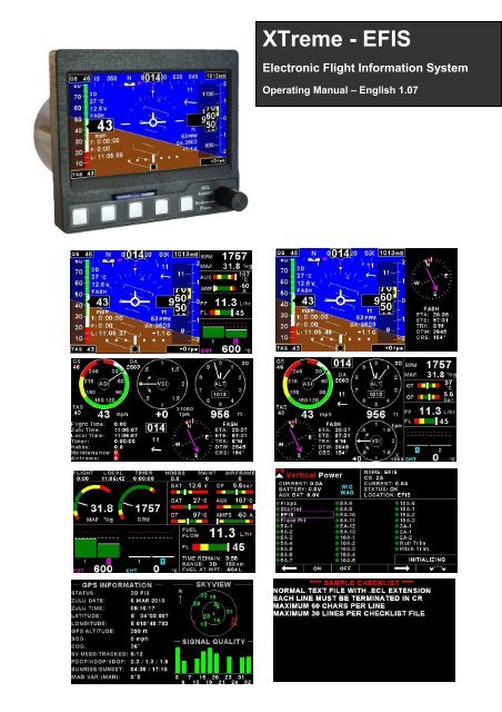
<strong>XTreme</strong> - <strong>EFIS</strong><br />
Electronic Flight Information System<br />
Operating Manual – English 1.07
<strong>XTreme</strong>-<strong>EFIS</strong> Operating Manual Page 2<br />
Introduction<br />
The <strong>XTreme</strong> is a compact, multifunction electronic flight information system intended as a main flight instrument in smaller<br />
aircraft or as a backup/secondary flight instrument in larger aircraft. The <strong>XTreme</strong>, which fits a standard 3 1/8” instrument<br />
panel hole, contains all the necessary functionality to replace several flight and engine monitoring instruments.<br />
All information is displayed in an easy to read format on a high resolution wide viewing angle 4.3” sunlight readable color<br />
display.<br />
The <strong>XTreme</strong>'s light weight, small size and high level of functionality makes it an excellent choice for all types of noncertified<br />
aircraft.<br />
1 Features<br />
Hardware:<br />
• Powerful 32 bit ARM processor<br />
• 4.3” high resolution 480x272, sunlight readable, wide viewing angle, 600 nits TFT LCD display<br />
• LED backlight (brightness can be adjusted for low light flying conditions)<br />
• Fits standard 3 1/8” aircraft instrument panel hole<br />
• SD Card interface for data recording, user splash screens, checklists, graphic information pages, firmware<br />
upgrades, navigation and route files etc<br />
• 1/8” NPT female fittings for Altitude and Airspeed pitot tube connections<br />
• 1x RS232 communication port (Altitude encoder/VP-X/CO Monitor)<br />
• 1x <strong>MGL</strong> <strong>Avionics</strong> Airtalk communication port<br />
• 1x <strong>MGL</strong> <strong>Avionics</strong> RDAC communications port<br />
• 1x CAN communication port<br />
• Rotary control plus 5 independent buttons for easy menu navigation and user input<br />
• External alarm switch output for an external indicator lamp etc<br />
• Built in 50 Channel GPS receiver with over 1 million effective correlators with high immunity to jamming<br />
• GPS Time To First Fix (TTFF) of less than 1 second<br />
• External active GPS antenna connection<br />
• Support for an internal or an external GPS receiver<br />
• Built in RTC (Real Time Clock)<br />
• Wide input supply voltage range of 8 to 30V DC<br />
• Built in voltage reversal and over voltage protection for harsh electrical environments<br />
• Light weight design<br />
<strong>EFIS</strong>:<br />
• Attitude display. Note (1)<br />
• Magnetic heading indication. Note (2)<br />
• Heading bug<br />
• Precision altimeter from –1000ft up to a maximum of 30 000ft (-304m to 9144m). Altitude can be displayed<br />
in feet or meters.<br />
• Altitude bug<br />
• Airspeed indicator (16mph to 250mph), 1mph resolution. Airspeed can be displayed in mph, km/h or kts<br />
• Digital and analog VSI indicator . Scale of 1000ft/min, 2000ft/min and 4000ft/min / 5m/s, 10m/s, and 20m/s.<br />
Resolution of 1ft/min, 1m/s<br />
• Serial Altitude encoder output via the RS232 port<br />
• Density altimeter<br />
• OAT (Outside Air Temperature) display using an external OAT probe<br />
• Supply Voltage display<br />
• Stopwatch timer<br />
• Automatic/Manual flight timer<br />
• RTC (Real Time Clock)<br />
• Glide and climb ratio indicator
<strong>XTreme</strong>-<strong>EFIS</strong> Operating Manual Page 3<br />
• Barometer (actual local pressure)<br />
• TAS (true airspeed) display<br />
• G-Force indication. Note (1)<br />
• Wind speed and wind direction indication. Note (2)<br />
• Turn Indicator. Note (1)<br />
• Slip/Skid indicator. Note (1)<br />
• CDI indicator<br />
• Waypoint and Route navigation<br />
• GPS Flight Path (calculated artificial horizon based on GPS information)<br />
• CO Monitor. Note (5)<br />
Engine Monitor: Note (3)<br />
• 1x Engine RPM<br />
• 1x Rotor RPM<br />
• 1x Manifold pressure<br />
• 1x Oil pressure input<br />
• 1x Oil temperature input<br />
• 2x Auxiliary analog channels (Pressure/Temperature/Current)<br />
• 12 Channel EGT/CHT display<br />
• 2x Fuel Flow<br />
• 2x Fuel Level<br />
• Special Rotax 912/914 engine monitor mode utilizing the standard built in Rotax NTC CHT probes<br />
• Programmable maintenance timer for scheduled routine engine maintenance<br />
• Engine display screens are automatically configured to optimize screen space depending on what<br />
parameters are been displayed<br />
• User settable Hobbs meter (password protected)<br />
• Fuel range / endurance based on TAS or GPS ground speed<br />
• Supply Voltage display<br />
• Current monitor to measure charge/discharge currents. Note (4)<br />
• Engine leaning feature<br />
• Vertical Power VP-X display. Note (6)<br />
General:<br />
• Alarms on most displays<br />
• Programmable maintenance timer for scheduled routine engine maintenance<br />
• Programmable airframe timer for scheduled airframe maintenance.<br />
• Records maximum and minimum values of most displayed values<br />
• Built in black box recorder – records all flight data, engine, attitude and GPS data to SD card. Data can be<br />
exported to Google Earth, Microsoft Excel, etc.<br />
• Includes a 1000 entry automatic flight log (Records start date&time, flight time, pilot number, Hobbs time,<br />
maintenance time, max altitude, airspeed and VSI reached during the flight)<br />
• User configurable start up (Splash) screen<br />
• Unlimited configurable checklists<br />
• Unlimited configurable graphic information displays<br />
• Automatic or manual local magnetic variation<br />
• Dual menu system for quick item selection and user setups<br />
• Sunrise/Sunset calculator<br />
• Firmware upgrades via SD Card<br />
• 1 year limited warranty<br />
(1) Requires optional <strong>MGL</strong> <strong>Avionics</strong> AHRS sensor unit (SP4/SP5/SP7)<br />
(2) Requires optional <strong>MGL</strong> <strong>Avionics</strong> compass sensor unit (SP2/SP6)<br />
(3) Requires optional <strong>MGL</strong> <strong>Avionics</strong> RDAC (Engine monitor) unit<br />
(4) Requires optional <strong>MGL</strong> <strong>Avionics</strong> current monitor sensor<br />
(5) Requires optional CO Guardian CO detector<br />
(6) Requires optional Vertical Power VP-X unit.
<strong>XTreme</strong>-<strong>EFIS</strong> Operating Manual Page 4<br />
2 <strong>XTreme</strong> Layout<br />
2.1 Front layout<br />
4.3” high resolution (480x272),<br />
sunlight readable, wide viewing<br />
angle, 600 nits LCD display<br />
SD card slot<br />
Rotary control. Press<br />
to access the quick<br />
select menus<br />
Press for previous<br />
display screen<br />
Soft keys<br />
Press to advance to the<br />
next display screen<br />
2.2 Rear layout<br />
Fits into a standard<br />
3 1/8” instrument<br />
Panel hole<br />
M4 Mounting Bolts<br />
GPS Antenna<br />
connection<br />
D15 Input connector<br />
(Power,Communications,<br />
OAT probe and alarm output )<br />
1/8” NPT Pressure port<br />
(Pitot tube)<br />
1/8” NPT Static Port
<strong>XTreme</strong>-<strong>EFIS</strong> Operating Manual Page 5<br />
3 Display Screens<br />
Press the left or right most soft keys to cycle through the display screens. The display screens can be enabled/disabled in<br />
the “DISPLAY SETUP” menu option.<br />
<strong>EFIS</strong> DISPLAY <strong>EFIS</strong>/EMS DISPLAY <strong>EFIS</strong>/HSI DISPLAY<br />
VFR DISPLAY VFR/EMS DISPLAY EMS DISPLAY<br />
ELECTRICAL SYSTEM DISPLAY GPS DISPLAY CHECKLIST/INFO DISPLAY
<strong>XTreme</strong>-<strong>EFIS</strong> Operating Manual Page 6<br />
3.1 <strong>EFIS</strong> display<br />
The <strong>EFIS</strong> information is displayed in a full screen format.<br />
3.1.1 Heading tape<br />
The heading tape is located at the top of the <strong>EFIS</strong> screen. The heading bug will be displayed in yellow if it is in the view<br />
area else it will turn cyan. The heading bug will always point to the shortest direction to achieve the correct heading. The<br />
heading bug can be changed in the quick select menu. The heading is corrected for attitude while pitching and rolling<br />
(<strong>MGL</strong> <strong>Avionics</strong> AHRS unit required (SP4/SP5/SP7)).The Compass parameters can be configured in the “COMPASS<br />
SETUP” menu. The small magenta triangle indicates coarse over ground from the GPS receiver. The coarse over ground<br />
indicator will only be displayed when a valid 2D or 3D GPS fix has been achieved. The heading tape source of information<br />
can be from a magnetic sensor (<strong>MGL</strong> <strong>Avionics</strong> SP2/6) or from the coarse over ground value from the GPS receiver. When<br />
the heading source of information is from the GPS receiver then the heading will be displayed in magenta.<br />
3.1.2 Ground Speed<br />
This is located in the top left corner of the <strong>EFIS</strong> display. The ground speed value will only be displayed when a valid 2D<br />
or 3D GPS fix has been achieved.<br />
3.1.3 Local Pressure Settings (QNH)<br />
This is located in the top right corner of the <strong>EFIS</strong> display. Turn the rotary control to change the local pressure setting. The<br />
local pressure can be displayed in mB or in “HG.<br />
3.1.4 True Airspeed (TAS)<br />
This is located in the bottom left corner of the <strong>EFIS</strong> display.<br />
What is TAS and how is it calculated ?<br />
TAS is indicated airspeed (ASI) compensated for altitude and temperature. Often pilots ignore the effect of temperature<br />
and only take altitude into account when converting ASI to TAS. For practical purposes this is quite accurate and gives a<br />
good reflection on your true airspeed. Keeping in mind that ASI measurement is subject to errors caused by airflow<br />
around your aircraft, there seems little point in taking this calculation to absolute resolution.<br />
Again, we have decided to use a formula often used by pilots. This way the instrument reading will agree with what pilots<br />
are used to.<br />
Add 1.75% of IAS per 1000 ft (304.9 m) increase in altitude above sea level.<br />
We assume here that IAS = RAS (rectified air speed).
<strong>XTreme</strong>-<strong>EFIS</strong> Operating Manual Page 7<br />
3.1.5 Airspeed Tape<br />
This is located to the left of the <strong>EFIS</strong> display. The Vso (Min safe speed, landing), Vs1 (Min safe<br />
speed, normal), Vfe (Max flap speed), Vno(Max maneuvering speed) and Vne (Max exceed<br />
speed) can be configured in the “AIRSPEED SETUP” menu.<br />
Vne (Max exceed speed)<br />
Vno (Max maneuvering speed)<br />
Vfe (Max flap speed)<br />
Vs1 (Min safe speed, normal)<br />
Vso (min safe speed, landing)<br />
3.1.6 Information display area 1<br />
The 1 st line is the GPS fix status. AQ=Acquiring (Red text color), 2D=2D fix, 3D=3D fix.<br />
The 2 nd line is the OAT value. Outside air temperature can be measured using the external temperature probe. The OAT<br />
parameters can be configured in the “OAT SETUP” menu.<br />
The 3 rd line is the supply voltage value. The <strong>XTreme</strong> can measure the supply voltage up to 30Vdc. The supply voltage<br />
parameters can be configured in the “VOLTS SETUP” menu.<br />
The 4 th line is the short name of the currently selected active waypoint.<br />
3.1.7 Altitude Tape<br />
This is located to the right of the <strong>EFIS</strong> display. The altitude bug will be displayed in yellow if it is in the<br />
view area else it will turn cyan in color . The altitude bug can be changed in the quick select menu. The<br />
altitude parameters can be configured in the “ALTITUDE SETUP” menu.<br />
3.1.8 VSI displays<br />
The <strong>XTreme</strong> provides an analog VSI as well as a digital readout. The VSI scale can be set for a scale of<br />
1000ft/min, 2000ft/min or 4000ft/min / 5m/s, 10m/s, or 20m/s. The VSI parameters can be configured in the “VSI<br />
SETUP” menu.
<strong>XTreme</strong>-<strong>EFIS</strong> Operating Manual Page 8<br />
3.1.9 Information display area 2<br />
The 1 st line is the carbon monoxide PPM value from the CO Guardian Detector (CO Guardian detector required).<br />
The 2 nd line is the density altitude value. Density altitude is a perceived altitude that pertains to your current altitude and<br />
temperature (and to a lessor extent on your current moisture content of the air). Density altitude is relevant for<br />
performance calculations of your aircraft. Density altitude affects the performance of your engine, propeller and airfoils.<br />
The most noticeable affects of density altitude are length of take-off and landing runs and the ability of your aircraft to<br />
carry weight. There are several methods to calculate density altitude, all result in readings that are very close to each<br />
other. We decided to implement a popular formula that is often used by pilots to calculate density altitude at their location.<br />
T=Ambient temperature in degrees C<br />
Ts=15-.0019812*Pressure Altitude(ft)<br />
Density Altitude=Pressure Altitude(ft)+118.6*(T-Ts)<br />
The 3 rd line is the current G-Force value. (<strong>MGL</strong> <strong>Avionics</strong> AHRS unit required (SP4/SP5/SP7)).<br />
3.1.10 Timer area<br />
The 1 st line is the timer. The Timer can be configured in the quick select menus.<br />
The 2 nd line is the flight timer. The flight time is automatically reset to zero when a new flight is<br />
started (manual or automatic flight detection). The flight timer can be started in the quick select<br />
menu (Manual selection).<br />
The 3 rd line is the local time. Local time normally includes a offset from Zulu time. The time offset<br />
can be setup in the “TIMERS SETUP” menu.<br />
3.1.11 Slip/Skid indicator<br />
This is located at the bottom of the display. The source of information for this indicator is derived from the accelerometer<br />
aligned with the pitch axis of the aircraft, i.e. the acceleration forces acting in the direction of the wings. The slip/skid ball<br />
can be enabled/disabled in the “HORIZON SETUP” menu<br />
3.1.12 Turn indicator<br />
This is located under the compass tape. The left and right notches indicate a (correctly balanced) rate 1 turn (3º per<br />
second). Therefore 180º turn will take 1 minute, 360º turn will take 2 minutes. The turn indicator can be enabled/disabled<br />
in the “HORIZON SETUP” menu<br />
3.1.13 Horizon line, Roll and Pitch indicators<br />
The horizon line separates the ground from the sky just like a conventional gyro<br />
based artificial horizon. The ground color can be selected to be shown in green<br />
or brown.<br />
The roll markers have tick marks at 10, 20, 30, 45, 60 and 90 degrees of roll.<br />
The pitch markers are horizontal with the horizon and are equally spaced with 5<br />
degrees of separation between lines. The 10 degree pitch lines have a small<br />
pointer on each end which points towards the horizon.<br />
The bank indicator can be configured for a moving type or a stationary type.<br />
All the above parameters can be configured in the “HORIZON SETUP” menu.
<strong>XTreme</strong>-<strong>EFIS</strong> Operating Manual Page 9<br />
3.1.14 Wind speed and direction<br />
The <strong>XTreme</strong> has the ability to calculate and display the wind speed and direction.<br />
The following variables must be available in order to calculate the wind speed and wind direction<br />
-A valid 2D or 3D GPS fix (COG/SOG)<br />
-Magnetic heading (<strong>MGL</strong> <strong>Avionics</strong> magnetic compass is required (SP2/SP6))<br />
-TAS<br />
The wind speed and direction will only be displayed if a valid 2D or 3D GPS fix has not been achieved. The wind speed<br />
and direction will display incorrect information when not in a straight and level flight.<br />
3.1.15 CDI Indicator<br />
The CDI indicator will be displayed at the bottom of the <strong>EFIS</strong> display when the pilot has selected an active waypoint to fly<br />
to. The CDI bar moves off the center to indicate which direction you must fly in order to stay on the original coarse. If the<br />
CDI is to the left then fly left until the CDI Bar is in the center of the “tick” markers. The “tick” marker scale can be setup in<br />
the “GPS SETUP” menu.
<strong>XTreme</strong>-<strong>EFIS</strong> Operating Manual Page 10<br />
3.2 <strong>EFIS</strong> Quick Select Menu System<br />
Press the rotary control when the <strong>EFIS</strong> screen is displayed to access the <strong>EFIS</strong> quick select<br />
menu.<br />
MARK WAYPOINT:<br />
Select this menu option to mark a waypoint. The latitude, longitude and<br />
altitude are automatically set based on the current location. Enter a short<br />
name and long name for the waypoint so you can easily identify it. Press<br />
save once you have finished editing and to save the waypoint to the<br />
waypoint.ewd file.<br />
START FLIGHT:<br />
Select this option to manually start/stop a flight. This menu option is only shown if the <strong>XTreme</strong> is setup to select the<br />
manual flight option under the “FLIGHT LOG” setup menu. The flight timer “F”, “FLIGHT” or “FLIGHT TIME” text will flash<br />
to indicate that a valid flight is in progress.<br />
REALIGN AHRS:<br />
If the following message appears then you have to realign the AHRS. This is due to excessive<br />
maneuvering or exceeding the maximum bank, pitch or yaw rates. Select this function to<br />
indicated to the instrument that you are flying straight and level and that gravity tracking may be<br />
accelerated to ensure rapid realignment of the horizon.<br />
LEVEL PITCH:<br />
You can level the pitch of the artificial horizon should your aircraft fly “nose up” or “nose down” due to trim.<br />
ALTITUDE BUG:<br />
Use the rotary control to adjust the altitude bug. Press the “ON/OFF”<br />
soft key to enable or disable the altitude bug icon.
<strong>XTreme</strong>-<strong>EFIS</strong> Operating Manual Page 11<br />
HEADING BUG:<br />
Use the rotary control to adjust the heading bug. Press the “ON/OFF”<br />
soft key to enable or disable the heading bug.<br />
TIMER:<br />
Select this menu option to configure the timer. Use the rotary control to<br />
adjust the timers reset value. Press the “UP/DOWN” soft key to select<br />
whether the timer must count up or down, the “START/STOP” soft key to<br />
start or stop the timer and the “ON/OFF” soft key to enable or disable the<br />
timer.<br />
MIN/MAX:<br />
Select this menu option to display the maximum and minimum captured<br />
values. Press the “RESET” soft key to reset the min/max values to the<br />
current values.<br />
BACKLIGHT:<br />
Select this menu option to adjust the backlight brightness level. This may be desirable<br />
during low light flying conditions. Use the rotary control to adjust the brightness level.<br />
MENU:<br />
Select this menu option to enter the main menu system.
<strong>XTreme</strong>-<strong>EFIS</strong> Operating Manual Page 12<br />
3.3 AHRS Failure<br />
The <strong>EFIS</strong> display will have the following indicators crossed out in case of a AHRS failure (SP4/SP5/SP7).
<strong>XTreme</strong>-<strong>EFIS</strong> Operating Manual Page 13<br />
3.4 <strong>EFIS</strong>/EMS Display<br />
The <strong>EFIS</strong>/EMS displays the <strong>EFIS</strong> in a 2/3 screen format and the engine data in a 1/3 screen format.<br />
3.4.1 <strong>EFIS</strong> Display<br />
The 2/3 <strong>EFIS</strong> display is in the same layout format as the full <strong>EFIS</strong> display. Please see the section 3.1 for more<br />
information.<br />
3.4.2 RPM/Rotor/MAP display section<br />
The RPM/Rotor/MAP section will maximize the space according to which parameter is enabled. The RPM,Rotor and MAP<br />
parameters can be configured in the “EMS SETUP” menu.<br />
RPM,Rotor and MAP enabled.<br />
RPM and MAP enabled.<br />
RPM only.<br />
MAP only.<br />
If the RPM,Rotor and MAP displays are disabled then the Hobbs, maintenance and airframe<br />
timers will be shown.<br />
3.4.3 Oil Temperature, Oil Pressure, Current and Auxiliary analog display section
<strong>XTreme</strong>-<strong>EFIS</strong> Operating Manual Page 14<br />
This section displays the oil temperature, oil pressure, as well as the 2 auxiliary analog channels (display labels are<br />
configurable). If more then 2 channels are enabled then the display area will alternate at a 3 second interval. The oil<br />
temperature/pressure as well as the 2 auxiliary analog channels can be configured in the “EMS SETUP” menu.<br />
3.4.4 Fuel display section<br />
The <strong>XTreme</strong> supports dual fuel flow and dual fuel levels. The fuel section will automatically try and maximize the display<br />
area according to the fuel parameters selected. The <strong>XTreme</strong> has 20 different fuel modes of operation. The fuel<br />
parameters can be configured in the “FUEL SETUP” menu.<br />
3.4.4.1 Single fuel flow and calculated tank level (single tank)<br />
Single fuel flow and fuel level sender (single tank)<br />
Differential fuel flow and calculated tank level (single tank)<br />
Differential fuel flow and fuel level sender (single tank)<br />
Summed fuel flow and calculated tank level (single tank)<br />
Summed fuel flow and fuel level sender (single tank)<br />
3.4.4.2 Dual fuel flow and calculated tank levels (dual tank)<br />
Dual fuel flow and dual fuel level senders (dual tank)<br />
3.4.4.3 Single fuel flow and dual fuel level senders (dual tank)<br />
Single fuel flow, single fuel level sender, single calculated tank<br />
Differential fuel flow and dual fuel level senders (dual tank)<br />
Differential flow, single fuel level sender, single calculated tank<br />
Summed fuel flow and dual fuel level senders (dual tank)<br />
Summed fuel flow, single fuel level sender, single calculated tank<br />
Single/Differential/Summed fuel flow, single fuel level sender, single calculated tank<br />
These modes are nice for multiple fuel tanks whereby one or more tanks are difficult to insert level senders in. Potential<br />
problems such as those listed below can easily be diagnosed by doing side by side comparisons between a calculated<br />
and physical tank.<br />
• Leaks in the fuel system<br />
• Uneven drain of interconnected tanks<br />
• Malfunction of the level sender<br />
• Malfunction of the flow sender
<strong>XTreme</strong>-<strong>EFIS</strong> Operating Manual Page 15<br />
3.4.4.5 Single fuel flow only indicator<br />
This mode is displayed if either fuel flow 1 or fuel flow 2 is selected and no fuel level senders are selected.<br />
3.4.4.6 Dual fuel flow indicator<br />
This mode is displayed if both fuel flow 1and fuel flow 2 are selected and the fuel mode is selected for dual flow. Both fuel<br />
level senders are disabled.<br />
3.4.4.7 Single tank level indicator<br />
This mode is displayed if either fuel level 1 or fuel level 2 is selected. Both fuel flow senders are disabled.<br />
3.4.4.8 Dual tank level indicator<br />
This mode is displayed if both fuel level 1 and fuel level 2 are selected. Both fuel flow senders are disabled.<br />
3.4.4.9 Differential/Summed fuel flow<br />
This mode is displayed if both fuel flow 1 and fuel flow 2 are selected and the fuel mode is selected for either differential<br />
or summed.<br />
3.4.5 EGT/CHT display section<br />
The <strong>XTreme</strong> supports up to 12 thermocouples for EGTs/CHTs. The EGT/CHT section will<br />
automatically try and maximize the display area according to the number of EGTs/CHTs<br />
selected. The EGT/CHT parameters can be configured in the “EGT SETUP” and “CHT SETUP”<br />
menu.
<strong>XTreme</strong>-<strong>EFIS</strong> Operating Manual Page 16<br />
The EGT/CHT number will highlight to the indicated temperature value if “HIGHEST” is selected. The EGT highlight color<br />
is magenta, and the CHT color is cyan.<br />
High Alarm<br />
High Caution<br />
Maximum temperature<br />
reached indicator<br />
Temperature unit<br />
EGT/CHT group indicator<br />
Indicates highest value if<br />
“HIGHEST” is selected or<br />
the highlighted bar value<br />
if “SCANNING” is selected
<strong>XTreme</strong>-<strong>EFIS</strong> Operating Manual Page 17<br />
3.5 <strong>EFIS</strong>/EMS Quick Select Menu System<br />
Press the rotary control when the <strong>EFIS</strong>/EMS screen is displayed to access the quick select<br />
menu.<br />
MARK WAYPOINT:<br />
See section 3.2 for more information.<br />
START FLIGHT:<br />
See section 3.2 for more information.<br />
REALIGN AHRS:<br />
See section 3.2 for more information.<br />
LEVEL PITCH:<br />
See section 3.2 for more information.<br />
ALTITUDE BUG:<br />
See section 3.2 for more information.<br />
HEADING BUG:<br />
See section 3.2 for more information.<br />
FUEL REFILL:<br />
Select this menu option to refill a calculated fuel tank. Press the<br />
“FULL” soft key for a quick fill to the full reading in the tank setup<br />
menu. Press the “EXIT” soft key when done.
<strong>XTreme</strong>-<strong>EFIS</strong> Operating Manual Page 18<br />
FUEL TOTALS:<br />
Select this menu option to display the fuel totals. Press the<br />
“RESET” soft key to reset the totalisers to zero. Press the “EXIT”<br />
soft key when done.<br />
TIMER:<br />
See section 3.2 for more information.<br />
MIN/MAX:<br />
See section 3.2 for more information.<br />
BACKLIGHT:<br />
See section 3.2 for more information.<br />
MENU:<br />
Select this menu option to enter the main menu system.
<strong>XTreme</strong>-<strong>EFIS</strong> Operating Manual Page 19<br />
3.6 <strong>EFIS</strong>/HSI Display<br />
The <strong>EFIS</strong>/HSI displays the <strong>EFIS</strong> in a 2/3 screen format and the navigation information in a 1/3 screen format.<br />
3.6.1 <strong>EFIS</strong> Display<br />
The 2/3 <strong>EFIS</strong> display is in the same layout format as the full <strong>EFIS</strong> display. Please see the section 3.1 for more<br />
information.<br />
3.6.2 Navigation Display<br />
The <strong>XTreme</strong> displays the navigation information in a form of a HSI (Horizontal Situation<br />
Indicator)<br />
Heading:<br />
The yellow bar at the top points to your heading. It is also known as the lubber line.<br />
Compass Rose:<br />
The compass rose is the 360 degree circle around the HSI. It is broken down into 5 degree<br />
divisions.<br />
Heading Bug:<br />
The 2 yellow lines indicate the heading bug. The heading bug can be adjusted in the quick<br />
select menu system.<br />
Coarse Selector:<br />
The magenta arrow (Indicating that the information is coming the internal GPS) points in the<br />
direction which you must fly in order to reach the active waypoint.<br />
CDI (Coarse Deviation Indicator):<br />
The center line of the Coarse Selector moves off the center to indicate which direction you must fly in order to stay on the<br />
the original coarse. If the CDI is to the left then fly left until the CDI lines up with the Coarse selector. The “tick” marker<br />
scale can be setup in the “GPS SETUP” menu.<br />
Navigation Information:<br />
Under the HIS you will find the short name of the active waypoint. You will also find the following information:<br />
ETA: Estimated Time of Arrival.
<strong>XTreme</strong>-<strong>EFIS</strong> Operating Manual Page 20<br />
ETE: Estimated Time En Route.<br />
TRK: GPS ground track.<br />
DTW: Distance to waypoint.<br />
CRS: The current set coarse to the active waypoint.
<strong>XTreme</strong>-<strong>EFIS</strong> Operating Manual Page 21<br />
3.7 <strong>EFIS</strong>/HSI Quick Select Menu System<br />
Press the rotary control when the <strong>EFIS</strong>/HSI screen is displayed to access the quick select<br />
menu.<br />
MARK WAYPOINT:<br />
See section 3.2 for more information.<br />
START FLIGHT:<br />
See section 3.2 for more information.<br />
REALIGN AHRS:<br />
See section 3.2 for more information.<br />
LEVEL PITCH:<br />
See section 3.2 for more information.<br />
ALTITUDE BUG:<br />
See section 3.2 for more information.<br />
HEADING BUG:<br />
See section 3.2 for more information.<br />
TIMER:<br />
See section 3.2 for more information.<br />
MIN/MAX:<br />
See section 3.2 for more information.<br />
BACKLIGHT:<br />
See section 3.2 for more information.<br />
MENU:<br />
Select this menu option to enter the main menu system.
<strong>XTreme</strong>-<strong>EFIS</strong> Operating Manual Page 22<br />
3.8 VFR Display<br />
The VFR display shows the altitude, airspeed, VSI and navigation in a full screen format.<br />
3.8.1 Airspeed Dial<br />
This displays the airspeed as a traditional analog airspeed indicator. A digital readout of<br />
the airspeed value is also displayed below the dial. The Vso (min safe speed, landing),<br />
Vs1 (min safe speed, normal), Vfe (max flap speed), Vno(max maneuvering speed) and Vne<br />
(max exceed speed) can be configured in the “AIRSPEED SETUP” menu.<br />
3.8.2 Altitude Dial<br />
This displays the altitude as a traditional 3 needle analog altimeter. A digital readout of the<br />
altitude value is also displayed below the dial. The altitude parameters can be configured in the<br />
“ALTITUDE SETUP” menu.<br />
The local pressure setting (QNH) is located in the bottom center of the altitude dial. Turn the<br />
rotary control to change the local pressure setting. The local pressure can be displayed in mB<br />
or in “HG.<br />
3.8.3 VSI indicator<br />
This displays the VSI as a traditional VSI indicator. The scale and units can be configured in<br />
the “VSI SETUP” menu.
<strong>XTreme</strong>-<strong>EFIS</strong> Operating Manual Page 23<br />
3.8.4 Ground Speed<br />
This is located in the top left corner of the VFR display. The ground speed value will only be displayed when a valid 2D or<br />
3D GPS fix has been achieved.<br />
3.8.5 True Airspeed (TAS)<br />
Please see section 3.1.4 for more information.<br />
3.8.6 GPS Fix Status<br />
GPS fix status. AQ=acquiring (Red text color), 2D=2D fix, 3D=3D fix.<br />
3.8.7 Density Altitude<br />
Please see section 3.1.9 for more information.<br />
3.8.8 Wind speed and Direction<br />
Please see section 3.1.14 for more information.<br />
3.8.9 Heading Box<br />
The heading is corrected for attitude while pitching and rolling (<strong>MGL</strong> <strong>Avionics</strong> AHRS unit required (SP4/SP5/SP7)).The<br />
Compass parameters can be configured in the “COMPASS SETUP” menu. The heading source of information can be<br />
from a magnetic sensor (<strong>MGL</strong> <strong>Avionics</strong> SP2/6) or from the coarse over ground value from the GPS receiver. When the<br />
heading source of information is from the GPS receiver then the heading will be displayed in magenta.<br />
3.8.10 Information display area 1<br />
Flight Time:<br />
The flight time is automatically reset to zero when a new flight is started (manual or automatic flight detection). The text<br />
“FLIGHT TIME” will flash when a flight is active. The flight timer can be started in the quick select menu (Manual flight<br />
mode).<br />
Zulu Time:<br />
This is also know as UTC or GMT time. The RTC (real time clock) can be selected to either use the internal RTC or from<br />
the GPS (external or internal). The RTC can be setup in the “TIMERS SETUP” menu.<br />
Local Time:<br />
Local time normally includes an offset from Zulu time. The time offset can be setup in the “TIMERS SETUP” menu.
<strong>XTreme</strong>-<strong>EFIS</strong> Operating Manual Page 24<br />
Timer:<br />
The Timer can be configured in the quick select menu.<br />
Hobbs:<br />
The <strong>XTreme</strong> contains a password protected Hobbs timer. The Hobbs time can be set to the current known engine time in<br />
the “TIMERS SETUP” menu. The Hobbs timer will only increment when the RPM is greater then the “HOBBS MINIMUM<br />
RPM”.<br />
Maintenance:<br />
This timer is set in engine hours and it will count down to zero when the engine RPM is greater then the “HOBBS<br />
MINIMUM RPM” value as set in the “TIMERS SETUP”. A good use for this function is to set the hours until your next<br />
spark plug change or engine inspection.<br />
The purpose of this function is to assist you in determining remaining hours until maintenance will be required. It is not<br />
intended as a replacement for the aircraft's maintenance log. It is therefore important that the aircraft's maintenance log<br />
be maintained in the normal manner. You should further use your own discretion in performing maintenance earlier than<br />
indicated should any aircraft performance problems arise.<br />
A maximum of 999 hours can be entered as a maintenance interval. A<br />
reminder message will appear on startup when zero hours are<br />
remaining. The reminder message will automatically disappear after 10<br />
seconds or if the pilot presses any key. Engine running time for the<br />
purpose of the maintenance timer is defined as the run time where the engine RPM is greater than the “HOBBS<br />
MINIMUM RPM” value as set in the “TIMERS SETUP”.<br />
Airframe:<br />
This timer operates similar to the engine maintenance timer but is based on flight time. You might use it to schedule<br />
thorough airframe checks at intervals..<br />
A reminder message will appear on startup when zero hours are remaining. The<br />
reminder message will automatically disappear after 10 seconds or if the pilot<br />
presses any key.<br />
3.8.11 Information area 2<br />
Volts:<br />
The <strong>XTreme</strong> can measure the supply voltage up to 30Vdc. The supply volts parameters can be configured in the “VOLTS<br />
SETUP” menu.<br />
OAT:<br />
Outside air temperature can be measured using the external temperature probe. The OAT parameters can be configured<br />
in the “OAT SETUP” menu.<br />
Glide Ratio:<br />
Glide ratio can be measured up to 1:99. Glide ratio is measured as a ratio between forward movement of the aircraft vs.<br />
vertical sink rate. Please note that the forward movement of the aircraft is not synonymous with horizontal forward<br />
movement relative to the earth surface but is a function of airspeed.
<strong>XTreme</strong>-<strong>EFIS</strong> Operating Manual Page 25<br />
Climb Ratio:<br />
Climb ratio can be measured up to 1:99. Climb ratio is measured as a ratio between forward movement of the aircraft vs.<br />
vertical climb rate. Please note that the forward movement of the aircraft is not synonymous with horizontal forward<br />
movement relative to the earth surface but is a function of airspeed.<br />
Barometer:<br />
Ambient pressure can be displayed in either millibar (mb) or in Inches of Mercury (“Hg). The setup for the “PRESSURE<br />
UNIT” in the “ALTITUDE SETUP” menu will determine which.<br />
3.8.12 Navigation Display<br />
Please see section 3.6.2 for more information.
<strong>XTreme</strong>-<strong>EFIS</strong> Operating Manual Page 26<br />
3.9 VFR Quick Select Menu System<br />
Press the rotary control when the VFR display screen is displayed to access the quick<br />
select menu.<br />
MARK WAYPOINT:<br />
See section 3.2 for more information.<br />
START FLIGHT:<br />
See section 3.2 for more information.<br />
HEADING BUG:<br />
See section 3.2 for more information.<br />
TIMER:<br />
See section 3.2 for more information.<br />
MIN/MAX:<br />
See section 3.2 for more information.<br />
BACKLIGHT:<br />
See section 3.2 for more information.<br />
MENU:<br />
Select this menu option to enter the main menu system.
<strong>XTreme</strong>-<strong>EFIS</strong> Operating Manual Page 27<br />
3.10 VFR/EMS Display<br />
The VFR display shows the altitude, airspeed and VSI in the traditional round gauges with 1/3 of the screen reserved for<br />
engine data.<br />
3.10.1 Airspeed Dial<br />
This displays the airspeed as a traditional analog airspeed indicator. A digital readout of<br />
the airspeed value is also displayed below the dial. The Vso (min safe speed, landing), Vs1<br />
(min safe speed, normal), Vfe (max flap speed), Vno(max maneuvering speed) and Vne (max<br />
exceed speed) can be configured in the “AIRSPEED SETUP” menu.<br />
3.10.2 Altitude Dial<br />
This displays the altitude as a traditional 3 needle analog altimeter. A digital readout of the<br />
altitude value is also displayed below the dial. The altitude parameters can be configured in the<br />
“ALTITUDE SETUP” menu.<br />
The local pressure setting (QNH) is located in the bottom center of the altitude dial. Turn the<br />
rotary control to change the local pressure setting. The local pressure can be displayed in mB or<br />
in “HG.<br />
3.10.3 VSI indicator<br />
This displays the VSI as a traditional VSI indicator. The scale and units can be configured in the<br />
“VSI SETUP” menu.
<strong>XTreme</strong>-<strong>EFIS</strong> Operating Manual Page 28<br />
3.10.4 Ground Speed<br />
This is located in the top left corner of the VFR display. The ground speed value will only be displayed when a valid<br />
2D or 3D GPS fix has been achieved.<br />
3.10.5 True Airspeed (TAS)<br />
Please see section 3.1.4 for more information.<br />
3.10.6 GPS Fix Status<br />
GPS fix status. AQ=acquiring (Red text color), 2D=2D fix, 3D=3D fix.<br />
3.10.7 Density Altitude<br />
Please see section 3.1.9 for more information.<br />
3.10.8 Wind speed and Direction<br />
Please see section 3.1.14 for more information.<br />
3.10.9 Heading Box<br />
The heading is corrected for attitude while pitching and rolling (<strong>MGL</strong> <strong>Avionics</strong> AHRS unit required (SP4/SP5/SP7)).The<br />
Compass parameters can be configured in the “COMPASS SETUP” menu. The heading source of information can be<br />
from a magnetic sensor (<strong>MGL</strong> <strong>Avionics</strong> SP2/6) or from the coarse over ground value from the GPS receiver. When the<br />
heading source of information is from the GPS receiver then the heading will be displayed in magenta.<br />
3.10.10 Information display area 1<br />
Flight Time:<br />
The flight time is automatically reset to zero when a new flight is started (manual or automatic flight detection). The text<br />
“FLIGHT TIME” will flash when a flight is active. The flight timer can be started in the quick select menu (Manual flight<br />
mode).<br />
Zulu Time:<br />
This is also know as UTC or GMT time. The RTC (real time clock) can be selected to come from the internal RTC or from<br />
the GPS (external or internal). The RTC can be setup in the “TIMERS SETUP” menu.<br />
Local Time:<br />
Local time normally includes an offset from Zulu time. The time offset can be setup in the “TIMERS SETUP” menu.<br />
Timer:<br />
The Timer can be configured in the quick select menu.
<strong>XTreme</strong>-<strong>EFIS</strong> Operating Manual Page 29<br />
Hobbs:<br />
The <strong>XTreme</strong> contains a password protected Hobbs timer. The Hobbs time can be set to the current known engine time in<br />
the “TIMERS SETUP” menu. The Hobbs timer will only increment when the RPM is greater then the “HOBBS MINIMUM<br />
RPM”.<br />
Maintenance:<br />
This timer is set in engine hours and it will count down to zero when the engine RPM is greater then the “HOBBS<br />
MINIMUM RPM” value as set in the “TIMERS SETUP”. A good use for this function is to set the hours until your next<br />
spark plug change or engine inspection.<br />
The purpose of this function is to assist you in determining remaining hours until maintenance will be required. It is not<br />
intended as a replacement for the aircraft's maintenance log. It is therefore important that the aircraft's maintenance log<br />
be maintained in the normal manner. You should further use your own discretion in performing maintenance earlier than<br />
indicated should any aircraft performance problems arise.<br />
A maximum of 999 hours can be entered as a maintenance interval. A<br />
reminder message will appear on startup when zero hours are<br />
remaining. The reminder message will automatically disappear after 10<br />
seconds or if the pilot presses any key. Engine running time for the<br />
purpose of the maintenance timer is defined as the run time where the engine RPM is greater than the “HOBBS<br />
MINIMUM RPM” value as set in the “TIMERS SETUP”.<br />
Airframe:<br />
This timer operates similar to the engine maintenance timer but is based on flight time. You might use it to schedule<br />
thorough airframe checks at intervals, perhaps every 25 or 50 hours.<br />
A reminder message will appear on startup when zero hours are remaining. The<br />
reminder message will automatically disappear after 10 seconds or if the pilot<br />
presses any key.<br />
3.10.11 Information area 2<br />
Volts:<br />
The <strong>XTreme</strong> can measure the supply voltage up to 30Vdc. The supply volts parameters can be configured in the “VOLTS<br />
SETUP” menu.<br />
OAT:<br />
Outside air temperature can be measured using the external temperature probe. The OAT parameters can be configured<br />
in the “OAT SETUP” menu.<br />
Glide Ratio:<br />
Glide ratio can be measured up to 1:99. Glide ratio is measured as a ratio between forward movement of the aircraft vs.<br />
vertical sink rate. Please note that the forward movement of the aircraft is not synonymous with horizontal forward<br />
movement relative to the earth surface but is a function of airspeed.<br />
Climb Ratio:<br />
Climb ratio can be measured up to 1:99. Climb ratio is measured as a ratio between forward movement of the aircraft vs.<br />
vertical climb rate. Please note that the forward movement of the aircraft is not synonymous with horizontal forward<br />
movement relative to the earth surface but is a function of airspeed.
<strong>XTreme</strong>-<strong>EFIS</strong> Operating Manual Page 30<br />
Barometer:<br />
Ambient pressure can be displayed in either millibar (mb) or in Inches of Mercury (“Hg). The setup for the “PRESSURE<br />
UNIT” in the “ALTITUDE SETUP” menu will determine which.<br />
3.10.12 Navigation Page<br />
Please see section 3.6.2 for more information.
<strong>XTreme</strong>-<strong>EFIS</strong> Operating Manual Page 31<br />
3.11 VFR Quick Select Menu System<br />
Press the rotary control when the VFR screen is displayedto access the VFR quick select<br />
menu.<br />
MARK WAYPOINT:<br />
See section 3.2 for more information.<br />
START FLIGHT:<br />
See section 3.2 for more information.<br />
FUEL REFILL:<br />
See section 3.5 for more information.<br />
FUEL TOTALS:<br />
See section 3.5 for more information.<br />
TIMER:<br />
See section 3.2 for more information.<br />
MIN/MAX:<br />
See section 3.2 for more information.<br />
BACKLIGHT:<br />
See section 3.2 for more information.<br />
MENU:<br />
Select this menu option to enter the main menu system.
<strong>XTreme</strong>-<strong>EFIS</strong> Operating Manual Page 32<br />
3.12 EMS Display<br />
The engine data is displayed in a full screen format.<br />
3.12.1 Information bar<br />
FLIGHT:<br />
The flight time is automatically reset to zero when a new flight is started (manual or automatic flight detection). The text<br />
“FLIGHT” will flash when a flight is active. The flight timer can be started in the quick select menu (Manual flight mode).<br />
LOCAL:<br />
Local time normally includes an offset from Zulu time. The time offset can be setup in the “TIMERS SETUP” menu.<br />
TIMER:<br />
See section 3.2 for more information.<br />
HOBBS:<br />
See section 3.6.9 for more information.<br />
MAINT:<br />
See section 3.6.9 for more information.<br />
Airframe:<br />
See section 3.6.9 for more information.<br />
3.12.2 RPM/Rotor/MAP display section<br />
The RPM/Rotor/MAP section will maximize the space according to which parameter RPM/Rotor/MAP is enabled. The<br />
RPM,Rotor and MAP parameters can be configured in the “EMS SETUP” menu.<br />
RPM,Rotor and MAP enabled.
<strong>XTreme</strong>-<strong>EFIS</strong> Operating Manual Page 33<br />
RPM and MAP enabled.<br />
RPM only enabled<br />
MAP only enabled<br />
3.12.3 Volts, OAT, Oil Temperature/Pressure, Current and Auxiliary Analog section<br />
This section displays the supply voltage, OAT, oil temperature, oil pressure, as well as the 2 auxiliary analog channels.<br />
The oil temperature/pressure as well as the 2 auxiliary analog channels can be configured in the “EMS SETUP” menu.<br />
3.12.4 Fuel display section<br />
The <strong>XTreme</strong> supports dual fuel flow and dual fuel levels. The fuel section will automatically try and maximize the display<br />
area according to the fuel parameters selected. The <strong>XTreme</strong> has 20 different fuel modes of operation. The fuel<br />
parameters can be configured in the “FUEL SETUP” menu. See section 0.0 for more information.<br />
3.12.4.1 Single fuel flow and calculated tank level (single tank)<br />
Single fuel flow and fuel level sender (single tank)<br />
Differential fuel flow and calculated tank level (single tank)<br />
Differential fuel flow and fuel level sender (single tank)<br />
Summed fuel flow and calculated tank level (single tank)<br />
Summed fuel flow and fuel level sender (single tank)
<strong>XTreme</strong>-<strong>EFIS</strong> Operating Manual Page 34<br />
3.12.4.2 Dual fuel flow and calculated tank levels (dual tank)<br />
Dual fuel flow and dual fuel level senders (dual tank)<br />
3.12.4.3 Single fuel flow and dual fuel level senders (dual tank)<br />
Single fuel flow, single fuel level sender, single calculated tank<br />
Differential fuel flow and dual fuel level senders (dual tank)<br />
Differential flow, single fuel level sender, single calculated tank<br />
Summed fuel flow and dual fuel level senders (dual tank)<br />
Summed fuel flow, single fuel level sender, single calculated tank<br />
Single/Differential/Summed fuel flow, single fuel level sender, single calculated tank<br />
These modes are nice for multiple fuel tanks whereby one or more tanks are difficult to insert level senders in. Potential<br />
problems such as those listed below can easily be diagnosed by doing side by side comparisons between a calculated<br />
and physical tank.<br />
• Leaks in the fuel system<br />
• Uneven drain of interconnected tanks<br />
• Malfunction of the level sender<br />
• Malfunction of the flow sender<br />
3.12.4.5 Single fuel flow only indicator<br />
This mode is displayed if either fuel flow 1 or fuel flow 2 is selected and no fuel level senders are selected.
<strong>XTreme</strong>-<strong>EFIS</strong> Operating Manual Page 35<br />
3.12.4.6 Dual fuel flow indicator<br />
This mode is displayed if both fuel flow 1and fuel flow 2 are selected and the fuel mode is selected for dual flow. Both fuel<br />
level senders are disabled.<br />
3.12.4.7 Single tank level indicator<br />
This mode is displayed if either fuel level 1 or fuel level 2 is selected. Both fuel flow senders are disabled.<br />
3.12.4.8 Dual tank level indicator<br />
This mode is displayed if both fuel level 1 and fuel level 2 are selected. Both fuel flow senders are disabled.<br />
3.12.4.9 Differential/Summed fuel flow<br />
This mode is displayed if both fuel flow 1 and fuel flow 2 are selected and the fuel mode is selected for either differential<br />
or summed.
<strong>XTreme</strong>-<strong>EFIS</strong> Operating Manual Page 36<br />
3.12.4.10 Calculated Fuel Tanks<br />
Calculated fuel tanks will have the text “CALC” in the fuel bar to indicate that the fuel level is calculated from fuel flow and<br />
that it is not a physical measure of the fuel tank.<br />
3.12.4.10 Fuel at Waypoint and GPS Fix Status<br />
The Xtreme will display the fuel remaining at the waypoint once an active waypoint has been selected.<br />
The GPS fix status is located next to the fuel range. AQ=acquiring (Red text color), 2D=2D fix, 3D=3D fix.<br />
3.12.5 EGT/CHT display section<br />
The <strong>XTreme</strong> supports up to 12 thermocouples for EGTs/CHTs. The EGT/CHT section will automatically try and maximize<br />
the display area according to the number of EGTs/CHTs selected. The EGT/CHT parameters can be configured in the<br />
“EGT SETUP” and “CHT SETUP” menu.<br />
The EGT/CHT number will highlight to the indicated the temperature value if “HIGHEST” is selected. The EGT highlight<br />
color is magenta, and the CHT color is cyan.<br />
High Alarm<br />
Maximum temperature<br />
reached indicator<br />
High Caution<br />
EGT group indicator<br />
Temperature units<br />
EGT High alarm value<br />
Indicates highest value if<br />
“HIGHEST” is selected or<br />
the highlighted bar value<br />
if “SCANNING” is selected<br />
CHT High alarm value<br />
CHT group indicator
<strong>XTreme</strong>-<strong>EFIS</strong> Operating Manual Page 37<br />
3.13 EMS Quick Select Menu System<br />
Press the rotary control when the EMS screen is displayed to access the EMS quick select<br />
menu.<br />
MARK WAYPOINT:<br />
See section 3.2 for more information.<br />
START FLIGHT:<br />
See section 3.2 for more information.<br />
FUEL REFILL:<br />
See section 3.5 for more information.<br />
LEAN MODE:<br />
EGT information is also very useful for fuel mixture control. As the fuel mixture is leaned, so the exhaust gasses get<br />
hotter. This rise in temperature is a sign of increased combustion efficiency as the optimum mixture setting is approached.<br />
If the leaning progresses past a certain point however, the temperature will begin to drop. This temperature drop is the<br />
result of reduced energy output from the diminished fuel flow. The best operating mixture for aircraft engines is in the<br />
vicinity of this peak EGT reading. The <strong>XTreme</strong> has a special Leaning mode, which easily identifies the peak EGT<br />
condition allowing you to adjust your fuel mixture for best performance. Fuel mixture should be adjusted once you have<br />
decided on a suitable cruise power setting (typically 70%). Once leaning mode has been enabled, the "LEAN MODE"<br />
label is displayed at the bottom left of the EMS display to clearly differentiate it from the normal operating mode. As the<br />
fuel mixture is slowly leaned past the point at which the temperature begins to drop (by more than 10°C/15°F), the<br />
absolute EGT temperatures will change to show the EGT reading relative to this peak. The sequential order as each<br />
cylinder peaks is also shown as numeric text under the cylinder. Leaning mode can be canceled by pressing the soft key<br />
to “OFF” or by changing the display screen.<br />
EGT Temperature<br />
while leaning<br />
EGT Reading relative<br />
to first peaked cylinder<br />
Lean mode indictor<br />
2nd cylinder to peak<br />
1st cylinder to peak
<strong>XTreme</strong>-<strong>EFIS</strong> Operating Manual Page 38<br />
CRUISE MODE:<br />
Once cruise mode has been enabled, the "CRUISE MODE" label is displayed at<br />
the bottom of the EMS display to clearly differentiate it from the normal operating<br />
mode. All EGT and CHT readings are immediately sampled as reference<br />
temperatures for the cruise. The display then shows EGT and CHT values<br />
relative to this reference temperature. Cruise mode can be canceled by pressing<br />
the soft key to “OFF”.<br />
FUEL TOTALS:<br />
See section 3.5 for more information.<br />
TIMER:<br />
See section 3.2 for more information.<br />
MIN/MAX:<br />
See section 3.2 for more information.<br />
BACKLIGHT:<br />
See section 3.2 for more information.<br />
MENU:<br />
Select this menu option to enter the main menu system.
<strong>XTreme</strong>-<strong>EFIS</strong> Operating Manual Page 39<br />
3.14 Electrical System Display<br />
The electrical system page displays the electrical system/ECB (Electronic Circuit Breaker) information. The <strong>XTreme</strong><br />
supports the Vertical Power VP-X electrical system / ECB unit.<br />
Please note that the <strong>XTreme</strong> has only 1x RS232 serial port that can only have one piece of equipment connected to it.<br />
Equipment includes: serial altitude encoder, Electrical system (Vertical Power VP-X) and the CO Guardian carbon<br />
monoxide detector.<br />
3.14.1 Message Window<br />
This windows displays the status of the VP-X system.<br />
3.14.2 System Power Window<br />
This windows displays the main power values as reported by the VP-X system.<br />
3.14.3 WIGWAG mode<br />
This annunciator will indicate that the wigwag function has been activated on the VP-X system. Please see the<br />
Vertical Power VP-X documentation for further information.<br />
3.14.4 Device Information<br />
This window displays the highlighted devices name, circuit breaker current<br />
value, the current used by the device, status and location.
<strong>XTreme</strong>-<strong>EFIS</strong> Operating Manual Page 40<br />
Use the rotary control to view the desired device. The Circular dot<br />
indicates the following:<br />
Green dot: Device is on and ok.<br />
White dot: Device is off.<br />
Red Dot: Device is in a fault condition.<br />
The soft keys allow the user to manually turn on or off a device. If the<br />
device is in a fault condition, the ON/OFF soft keys are hidden and the<br />
RESET soft key is shown.<br />
3.15 Electrical System Quick Select Menu System<br />
Press the rotary control when the electrical system screen is shown to access the electrical<br />
system quick select menu.<br />
WIG-WAG:<br />
Select “AUTO” to activate the wigwag mode, or “STEADY” to cancel the wigwag mode.<br />
Please see the Vertical Power VP-X documentation for further information.<br />
MARK WAYPOINT:<br />
See section 3.2 for more information.<br />
START FLIGHT:<br />
See section 3.2 for more information.<br />
MIN/MAX:<br />
See section 3.2 for more information.<br />
BACKLIGHT:<br />
See section 3.2 for more information.<br />
MENU:<br />
Select this menu option to enter the main menu system.
<strong>XTreme</strong>-<strong>EFIS</strong> Operating Manual Page 41<br />
3.16 GPS Display<br />
The GPS page show the GPS information in an easy to read format. Sunrise/sunset times as well as the magnetic<br />
variation is shown.<br />
3.17 GPS Quick Select Menu System<br />
Press the rotary control when the GPS screen is shown to access the GPS quick select menu.<br />
MARK WAYPOINT:<br />
See section 3.2 for more information.<br />
START FLIGHT:<br />
See section 3.2 for more information.<br />
MIN/MAX:<br />
See section 3.2 for more information.<br />
BACKLIGHT:<br />
See section 3.2 for more information.<br />
MENU:<br />
Select this menu option to enter the main menu system.
<strong>XTreme</strong>-<strong>EFIS</strong> Operating Manual Page 42<br />
3.18 Information/Checklist Display<br />
The Information/Checklist page shows checklists and graphic information pages which are loadable from the SD card.<br />
3.18.1 Graphic information pages<br />
The graphic information page allows you to display any type of image on the <strong>XTreme</strong>s high resolution graphics display.<br />
Creating your own graphic information pages<br />
You will need:<br />
·A bitmap picture of your choice (*.BMP, 480x272 pixel resolution)<br />
·The Enigma BMP to MIF converter tool (can be downloaded free of charge from http://www.mglavionics.co.za or can be<br />
found on the <strong>XTreme</strong> distribution SD card).<br />
The Enigma BMP to MIF program is used to convert images in Windows BMP format to Enigma MIF format. You can use<br />
this program to make your own startup screen (Splash screen) and graphic information pages. The color depth is limited<br />
to Enigmas 256 colors.<br />
Run the Enigma BMP image to MIF format converter program.<br />
Load an image file (and remember the location), select the resolution as width (480) and height (272) and press the<br />
process button. The new MIF image will be located in the same directory as the source (.BMP) file. Copy the created file<br />
(.MIF extension) to the Infopage directory on the SD card.<br />
The graphic information file can then be loaded by pressing the rotary<br />
control and selecting “INFO PAGES”. A window containing all the files<br />
with the .MIF extension is shown. Select the desired information page.<br />
The number of information pages that can be stored and displayed<br />
depends on the size of the SD card.<br />
3.18.2 Checklists<br />
A checklist file is simply a text file created in a word processing program and saved with a .ECL extension. The name of<br />
the file does not matter but we suggest calling it something familiar so you can easily identify it. The length of each text<br />
line must not be more then 60 characters and must be terminated with an Enter (CR). The line will automatically be<br />
truncated at the end of the right hand side of the screen. Each checklist file must not be more then 30 lines.
<strong>XTreme</strong>-<strong>EFIS</strong> Operating Manual Page 43<br />
Copy the created file (.ECL extension) to the checklst directory on the<br />
SD card when you are complete. The checklist file can be loaded by<br />
pressing the rotary control and selecting “CHECKLISTS”. A window<br />
containing all the files with the .ECL extension will shown. Select the<br />
checklist you require. The number of checklists that can be stored and<br />
displayed depends on the size of the SD card.<br />
3.19 Information/Checklist Quick Select Menu System<br />
Press the rotary control when the Info/Checklist screen is shown to access the Info/checklist<br />
quick select menu.<br />
MARK WAYPOINT:<br />
See section 3.2 for more information.<br />
START FLIGHT:<br />
See section 3.2 for more information.<br />
INFO PAGES:<br />
This menu option selects a graphic information page to display. A window will open displaying all the files with the .MIF<br />
extension in the Infopage directory on the SD card. Press the rotary control over the file you wish to load as a graphic<br />
information page.<br />
CHECKLISTS:<br />
This menu option selects a checklist to display. A window will open displaying all the files with the .XCL extension in the<br />
Checklst directory on the SD card. Press the rotary control over the file you wish to load as a checklist.<br />
MIN/MAX:<br />
See section 3.2 for more information.<br />
BACKLIGHT:<br />
See section 3.2 for more information.<br />
MENU:<br />
Select this menu option to enter the main menu system.
<strong>XTreme</strong>-<strong>EFIS</strong> Operating Manual Page 44<br />
3.20 Waypoints<br />
The <strong>XTreme</strong> has 2 databases that it uses for waypoints. A “NAVIDATA” and a user “SUPPLEMENTARY” database.<br />
The Navidata database is compiled by the <strong>MGL</strong> Central application. There are precompiled navidata databases for most<br />
countries on the <strong>XTreme</strong> distribution SD Card and also from various <strong>MGL</strong> websites. Alternatively Waypoint and airport<br />
data can be obtained for many areas of the world through the free service provided at www.navaid.com web site.<br />
Download data for your region in GPX format. This can be imported into the <strong>MGL</strong> Central application. Please note that<br />
the navidata database must be in a version 5 format and must not be encrypted. If you are unsure of the version then<br />
import the navidata file into the latest version of the <strong>MGL</strong> central application and then re-export it again. THE<br />
NAVIDATA.EWD FILE MUST RESIDE IN THE ROOT DIRECTORY OF THE SD CARD.<br />
The user “Supplementary” database is the database that can be created and edited on the Xtreme using the waypoint<br />
menu or in the <strong>MGL</strong> central application. The file must be called waypoint.ewd and it must RESIDE IN THE ROOT<br />
DIRECTORY OF THE SD CARD. Waypoints that are created using the mark function in the quick select menu are saved<br />
in this database.<br />
Press the 2 nd most left softkey during the normal display screens to access the waypoint selection screen. The following<br />
screen will be displayed:<br />
N: Waypoint is in the navidata database.<br />
W: Waypoint is in the supplemental database.<br />
Distance to waypoint from<br />
the current location<br />
6 Character short Waypoint<br />
name.<br />
Long Waypoint name.<br />
Page up and Page down<br />
softkeys.<br />
Scroll up and down through<br />
the waypoint list<br />
The nearest 100 waypoints to your current location is displayed.
<strong>XTreme</strong>-<strong>EFIS</strong> Operating Manual Page 45<br />
Searching Waypoints:<br />
Press the search waypoint to search the navigation databases if the required waypoint is not in the list. The following<br />
screen is displayed:<br />
Use the rotary control to enter the search string for the short name. Once the required waypoint is visible in the list press<br />
the “LIST” softkey. Use the rotary control to scroll up and down the list. Press the rotary control to select the required<br />
waypoint.
<strong>XTreme</strong>-<strong>EFIS</strong> Operating Manual Page 46<br />
3.21 Routes<br />
The <strong>XTreme</strong> has the ability to fly preset routes. Press the middle softkey during the normal display screens to access the<br />
route selection screen. The following screen will be displayed:<br />
Once a route has been selected then select the route flying direction<br />
The first or last waypoint will be selected depending on which direction was selected.
<strong>XTreme</strong>-<strong>EFIS</strong> Operating Manual Page 47<br />
If the middle softkey is pressed again when a route is active then the following screen will be displayed.<br />
A new waypoint in the route can be selected, the flying direction can be changed or the route can be canceled.
<strong>XTreme</strong>-<strong>EFIS</strong> Operating Manual Page 48<br />
4 Main Menu System<br />
To access the main menu system, press the rotary control knob, scroll down to the “MENU”<br />
option and press the rotary control knob again. Use the rotary control to navigate through the<br />
menu system.<br />
4.1 Menu Sub-Bar<br />
Use the menu sub-bar for quick menu navigation. Select the soft key directly under the text to activate that function.
<strong>XTreme</strong>-<strong>EFIS</strong> Operating Manual Page 49<br />
4.2 Flight Log<br />
EXPORT FLIGHT LOG TO SD CARD:<br />
Use this function to export the current flight logs stored in the <strong>XTreme</strong> to a SD card. The exported filename is<br />
FLTLOG.LOG. The exported flight log can then be imported into the <strong>MGL</strong> <strong>Avionics</strong> Enigma Flight Planner software for<br />
editing and printing. Please see the Enigma Flight Planner software for further information.<br />
VIEW FLIGHT LOG:<br />
This allows the pilot to view the last 1000 recorded flights.<br />
ERASE FLIGHT LOG:<br />
Use this function to erase the current flight log stored in the <strong>XTreme</strong>.<br />
PILOT NUMBER:<br />
Select a pilot number under which the next flights will be logged. Every flight entry in the flight log has a pilot number<br />
associated to it.<br />
<strong>EFIS</strong> FLIGHT TIMER DISPLAY:<br />
This enables or disables the flight timer display on the <strong>EFIS</strong> and MFD displays.
<strong>XTreme</strong>-<strong>EFIS</strong> Operating Manual Page 50<br />
FLIGHT DETECT:<br />
Select if you want the flight log to automatically “AUTOMATIC” start or if you want to manually “MANUAL” start and stop<br />
it.<br />
The <strong>XTreme</strong> uses the following algorithm to determine if a flight is in progress (“AUTOMATIC” mode): If the airspeed is<br />
greater than the preset “FLIGHT DETECT MINIMUM ASI” value or the RPM is greater than the preset “FLIGHT DETECT<br />
MINIMUM RPM” value for a duration of 60 seconds or more, a flight is started with a logbook entry. The flight ends if<br />
airspeed or RPM falls below the preset value for 30 seconds.<br />
The above algorithm ensures that touch-and-goes will not result in the end of a flight and a logbook entry. Should the<br />
instrument be switched off during a flight, this will end the flight and the log will reflect the time until the instrument was<br />
switched off. Should the instrument be switched on again during a flight, a new flight will start for logging purposes<br />
FLIGHT DETECT MINIMUM RPM: (Automatic mode only)<br />
Enter the minimum RPM threshold that will start a new flight log entry.<br />
FLIGHT DETECT MINIMUM ASI: (Automatic mode only)<br />
Enter the minimum ASI threshold that will start a new flight log entry.
<strong>XTreme</strong>-<strong>EFIS</strong> Operating Manual Page 51<br />
4.3 Waypoint Setup<br />
The waypoint setup allows the pilot to edit the supplementary waypoint database.<br />
NEW WAYPOINT:<br />
Select this menu option to create a new waypoint.<br />
EDIT WAYPOINT:<br />
Select this menu option to edit a waypoint.<br />
Total number of<br />
waypoints in the<br />
waypoint.ewd file<br />
Waypoint short name<br />
Distance of waypoint<br />
From the current<br />
location<br />
Waypoint long name
<strong>XTreme</strong>-<strong>EFIS</strong> Operating Manual Page 52<br />
VIEW WAYPOINT:<br />
Select this menu option to view a waypoint.<br />
Total number of<br />
waypoints in the<br />
waypoint.ewd file<br />
Waypoint short name<br />
Distance of waypoint<br />
From the current<br />
location<br />
Waypoint long name
<strong>XTreme</strong>-<strong>EFIS</strong> Operating Manual Page 53<br />
DELETE WAYPOINT:<br />
Select this menu option to delete a waypoint.<br />
WAYPOINT DISPLAY TYPES:<br />
Select what type of waypoints to display when browsing/searching the navidata file. Selecting only the waypoint types of<br />
interest can speed up the database searching considerably.<br />
WAYPOINT MESSAGE ALERT:<br />
Enter the distance to the waypoint when the waypoint alert message must be displayed.
<strong>XTreme</strong>-<strong>EFIS</strong> Operating Manual Page 54<br />
4.4 Route Setup<br />
NEW ROUTE:<br />
Select this menu option to create a new route. A file with the route name and the extension .ert will be created. It will be<br />
created in the root directory of the SD card.<br />
ADD/INSERT WAYPOINT TO ROUTE:<br />
Select this menu option to add a waypoint to a route.
<strong>XTreme</strong>-<strong>EFIS</strong> Operating Manual Page 55<br />
REMOVE WAYPOINT FROM ROUTE:<br />
Select this menu option to remove a waypoint from a route.
<strong>XTreme</strong>-<strong>EFIS</strong> Operating Manual Page 56<br />
VIEW ROUTE:<br />
Select this menu option to view all the waypoints in a route.
<strong>XTreme</strong>-<strong>EFIS</strong> Operating Manual Page 57<br />
EDIT ROUTE NAME:<br />
Select this menu option to edit the route name.<br />
DELETE ROUTE:<br />
Select this menu option to delete a route.
<strong>XTreme</strong>-<strong>EFIS</strong> Operating Manual Page 58<br />
4.5 <strong>EFIS</strong> Setup
<strong>XTreme</strong>-<strong>EFIS</strong> Operating Manual Page 59<br />
4.5.1 Altitude Setup<br />
ALTITUDE UNIT:<br />
Select if you want the altitude displayed in ft (feet) or m (meters).<br />
PRESSURE UNIT:<br />
Select if you want the local pressure displayed in mB (millibars) or “Hg (inches of mercury).<br />
<strong>EFIS</strong> DENSITY ALTITUDE:<br />
This enables or disables the density altitude diisplay on the <strong>EFIS</strong> and MFD displays.<br />
ALTITUDE CALIBRATION FACTOR:<br />
On the rear of your <strong>XTreme</strong> instrument you will find the calibration factor that has been determined to ensure the most<br />
accurate reading of your altimeter. This is the value that should be entered here. Should you have access to an accurate<br />
reference you may use this function to calibrate your altimeter. Before you do this, ensure that your calibrated and<br />
certified reference is set to the local pressure of 1013.25mB (29.92”HG). Your altimeter has been calibrated by the factory<br />
to an accuracy of +/- one mB or approximately +/- 30 ft (10m) at sea level.<br />
SERIAL OUTPUT:<br />
Select “ON” to enable the RS232 serial altitude output. This formatted serial RS232 message can be directly interfaced to<br />
various RS232 serial input transponders. If a parallel Gillham output is required then a CNV-ALT2 can be purchased from<br />
your <strong>MGL</strong> <strong>Avionics</strong> distributor to convert the RS232 output to a parallel Gillham output. The RS232 is output on PIN 7<br />
(RS232 port 1 TXD)<br />
SERIAL PROTOCOL:<br />
Select the protocol of the serial RS232 output message. The protocol can be selected between GARMIN AT, Magellan,<br />
Northstar/Garmin, Trimble/Garmin, <strong>MGL</strong> <strong>Avionics</strong> and Microair UAV. Please note that the baud rate is automatically<br />
adjusted according to which protocol is selected. The output format is as follows. The message contains the current<br />
pressure altitude with a fixed reference to 1013.25mB (29.92 inches mercury). All protocols use 8 databits, no parity, and<br />
1 stop bit. The message is outputted once a second.<br />
Protocol Baud<br />
Rate<br />
Message format<br />
Garmin AT 1200 #AL, space, +/-, five altitude digits right<br />
justified zero padded, T+25, checksum,<br />
carriage return<br />
Example<br />
#AL +02372T+25DF[CR]<br />
The checksum is a simple modulo 256 sum<br />
of the binary values of the individual<br />
characters. The checksum is sent as two
<strong>XTreme</strong>-<strong>EFIS</strong> Operating Manual Page 60<br />
characters in hexadecimal format<br />
Magellan 1200 #<strong>MGL</strong>, +/-, five altitude digits right justified<br />
zero padded, T+25, checksum, carriage<br />
return<br />
The checksum is a simple modulo 256 sum<br />
of the binary values of the individual<br />
characters. The checksum is sent as two<br />
characters in hexadecimal format<br />
Northstar, 4800 ALT, space, five altitude digits right justified<br />
Garmin<br />
zero padded, carriage return<br />
Trimble,<br />
9600 ALT, space, five altitude digits right justified<br />
Garmin<br />
zero padded, carriage return<br />
<strong>MGL</strong> <strong>Avionics</strong> 9600 ALT, +/-, five altitude digits right justified<br />
zero padded ,1013.25mB (29.92”Hg)<br />
referenced, C, +/-, five altitude digits right<br />
justified zero padded (corrected to local<br />
pressure), L, local pressure setting in<br />
millibars,+/-, four digit VSI reading right<br />
justified zero padded in ft/min, X,<br />
checksum, carriage return<br />
The checksum is a simple modulo 256 sum<br />
of the binary values of the individual<br />
characters. The checksum is sent as two<br />
characters in hexadecimal format<br />
Microair UAV 9600 STX,a,=, five altitude digits right justified<br />
STX=0x02<br />
ETX=0x03<br />
CR=0x0D<br />
zero padded, ETX<br />
$<strong>MGL</strong>+02372T+2513[CR]<br />
ALT 02372[CR]<br />
ALT 02372[CR]<br />
ALT+02372C+02372L1013+0000XCA[<br />
CR]<br />
[STX]a=02372[ETX]<br />
SERIAL RESOLUTION:<br />
Select the resolution of the output altitude data, a selection of 1,10,25 or 100 ft can be selected.<br />
Please note that the <strong>XTreme</strong> has only 1x RS232 serial port that can only have one piece of equipment connected to it.<br />
Equipment includes: serial altitude encoder, Electrical system (Vertical Power VP-X) and the CO Guardian carbon<br />
monoxide detector.
<strong>XTreme</strong>-<strong>EFIS</strong> Operating Manual Page 61<br />
4.5.2 Airspeed Setup<br />
ZERO ASI SENSOR:<br />
This setup allows your instrument to measure<br />
the zero airspeed reading of the airspeed<br />
sensor and set a calibration value internally for<br />
this. This is equivalent to some mechanical<br />
airspeed indicators that have an<br />
adjustment to set the needle to zero when the<br />
aircraft is not moving. You would use this<br />
function occasionally if you see an airspeed<br />
reading when the aircraft is at rest. This may be<br />
caused by aging of the built in pressure sensor<br />
or related electronics. When this function is<br />
performed make sure that there is no air flow<br />
into the pitot tube as this would result in an<br />
incorrect internal calibration.<br />
ASI UNIT:<br />
Select if you want the ASI to be displayed in mph (statute miles per hour), km/h (kilometers per hour) or kts (nautical miles<br />
per hour).<br />
ASI FILTER:<br />
This function can be used to select the signal filter time constant. Selections are "NONE", “FAST” or “SLOW”. This<br />
selection influences the rate at which your ASI can change its reading. If you have an installation that suffers from strong<br />
turbulence at the pitot tube, select “slow”. If you have a very clean airflow in front of the pilot tube you can select “fast”<br />
which will give you a faster response to airspeed changes.<br />
ASI SPAN (TAPE&DIAL):<br />
Select the maximum value that you want the airspeed tape & dial displays to show. This can give you increased display<br />
resolution.<br />
ASI IN VIEW (TAPE):<br />
Adjust this setting to set the amount of tape to view. For example, setting this value to 30% and your "ASI SPAN" to 250<br />
will result in the tape showing 75 on the display at a time.
<strong>XTreme</strong>-<strong>EFIS</strong> Operating Manual Page 62<br />
Vne (MAX EXCEED SPEED):<br />
Enter you maximum speed you aircraft should not exceed.<br />
Vno(MAX MANEUVERING SPEED):<br />
Enter your maximum maneuvering speed.<br />
Vfe (MAX FLAP SPEED):<br />
Enter the maximum speed that is permissible with the flaps extended.<br />
Vs1 (MIN SAFE SPEED, NORMAL):<br />
Enter your minimum safe speed for normal flight of your aircraft<br />
Vso (MIN SAFE SPEED, LANDING):<br />
Enter your minimum safe speed for landing your aircraft<br />
Vs ALARM:<br />
This enables or disables Vs Alarm<br />
Vne ALARM:<br />
This enables or disables the VNE alarm.<br />
ASI CALIBRATION FACTOR:<br />
During the factory calibration a factor has been determined and entered here that will give you accurate airspeed,<br />
provided your pitot tube is not influenced by pressure effects caused by airflow around your airframe. The calibration is<br />
displayed in % of the reading, you can increase or decrease the reading if required to help cancel out under or over<br />
reading of the airspeed indicator on your aircraft. The original calibration factor has been written onto the back of your<br />
<strong>XTreme</strong> instrument.
<strong>XTreme</strong>-<strong>EFIS</strong> Operating Manual Page 63<br />
4.5.3 VSI Setup<br />
VSI UNIT:<br />
Select if you want the VSI to be displayed in "ft/min" (feet/minute) or "m/s" (meters/second).<br />
VSI SCALE:<br />
Select the VSI scale most suited for your aircraft.<br />
VSI CALIBRATION FACTOR:<br />
This is a function that is used to calibrate your VSI to read exact rates of climb or decent. This function works as a<br />
percentage of initial reading. The default setting for this function is 100%. Increasing this value increases the VSI reading<br />
and decreasing the value decreases the reading.<br />
Suggested VSI calibration method<br />
After you have installed the instrument, perform a calibration flight. This should be done in very calm conditions.<br />
Turbulence and thermal activity will make accurate calibration impossible. Many areas have ideal conditions during early<br />
mornings or late afternoons. Place the instrument in ft/min for ease of calibration. Take your aircraft to a few<br />
thousand feet above ground and start a glide with a low power setting. Take a stopwatch and when the glide is stable<br />
(stable VSI reading) start the stopwatch. Take note of your altimeter reading at the same time. Continue the stable glide<br />
for one minute exactly. After the minute has finished, take another reading of your altimeter.<br />
Example:<br />
VSI reading during stable glide: -400 ft/min<br />
Start altitude: 2500 ft.<br />
End altitude: 2050 ft.<br />
In the above example the VSI is under reading by about 12%. Set your VSI calibration to 112% to cancel out the error.
<strong>XTreme</strong>-<strong>EFIS</strong> Operating Manual Page 64<br />
4.5.4 Volts Setup<br />
<strong>EFIS</strong> VOLTS DISPLAY:<br />
This enables or disables the volts display on the <strong>EFIS</strong> and MFD displays.<br />
VOLTS DISPLAY MAX:<br />
Select the maximum value that you want the volts bargraph in the EMS display to show. This can give you increased<br />
display resolution.<br />
VOLTS DISPLAY MIN:<br />
Select the minimum value that you want the volts bargraph in the EMS display to show. This can give you increased<br />
display resolution.<br />
HIGH ALARM:<br />
This enables or disables the volts high alarm.<br />
HIGH ALARM:<br />
Enter the voltage threshold for when the high alarm must be activated. Any voltage above this value will activate the<br />
alarm.<br />
HIGH CAUTION:<br />
Enter the voltage for the high caution. This is the lower value of the upper yellow band.<br />
LOW CAUTION:<br />
Enter the voltage for the low caution. This is the upper value of the lower yellow band.<br />
LOW ALARM:<br />
This enables or disables the volts low alarm.<br />
LOW ALARM:<br />
Enter the voltage threshold for when the low alarm must be activated. Any voltage below this value will activate the alarm.<br />
VOLTS CALIBRATION FACTOR:<br />
During the factory calibration a factor has been determined and entered here that will give you an accurate volts reading.<br />
If you would like to adjust this value then measure the supply voltage with a multimeter and adjust the calibration factor<br />
until the Xtreme matches that of the multimeter.
<strong>XTreme</strong>-<strong>EFIS</strong> Operating Manual Page 65<br />
4.5.5 OAT Setup<br />
<strong>EFIS</strong> OAT DISPLAY:<br />
This enables or disables the OAT display on the <strong>EFIS</strong> and MFD displays.<br />
OAT DISPLAY MAX:<br />
Select the maximum temperature that you want the OAT bargraph in the EMS display to show. This can give you<br />
increased display resolution.<br />
OAT DISPLAY MIN:<br />
Select the minimum temperature that you want the OAT bargraph in the EMS display to show. This can give you<br />
increased display resolution.<br />
HIGH ALARM:<br />
This enables or disables the OAT high alarm.<br />
HIGH ALARM:<br />
Enter the temperature threshold for when the high alarm must be activated. Any temperature above this value will activate<br />
the alarm.<br />
HIGH CAUTION:<br />
Enter the temperature for the high caution. This is the lower value of the upper yellow band.<br />
LOW CAUTION:<br />
Enter the temperature for the low caution. This is the upper value of the lower yellow band.<br />
LOW ALARM:<br />
This enables or disables the OAT low alarm.<br />
LOW ALARM:<br />
Enter the temperature threshold for when the low alarm must be activated. Any temperature below this value will activate<br />
the alarm.<br />
OAT TEMPERATURE UNIT:<br />
Select whether you want the OAT to be displayed in degrees Celsius (ºC) or in degrees Fahrenheit (ºF).<br />
OAT CALIBRATION FACTOR:<br />
During the factory calibration a factor has been determined and entered here that will give you an accurate OAT reading.<br />
If you find this value is incorrect then adjust the calibration factor until the <strong>XTreme</strong>s OAT matches that of a precision<br />
thermometer. Calibration can only be done in Celcius (ºC).
<strong>XTreme</strong>-<strong>EFIS</strong> Operating Manual Page 66<br />
4.6 EMS Setup
<strong>XTreme</strong>-<strong>EFIS</strong> Operating Manual Page 67<br />
4.6.1 RPM Setup<br />
RPM DISPLAY:<br />
Select if you want the RPM to be displayed in “RPM” or “PERCENT” .If you do not want any RPM information then set this<br />
parameter to "OFF". If the rotor RPM is set to "RPM" or "PERECENT" then the engine RPM display will automatically be<br />
enabled.<br />
RPM 100% DISPLAY:<br />
Select the maximum value that you want the RPM to correlate to 100%.<br />
RPM DISPLAY MAX:<br />
Select the maximum RPM that you want the RPM dial to show. This can give you increased display resolution.<br />
RPM DISPLAY MIN:<br />
Select the minimum RPM that you want the RPM dial to show. This can give you increased display resolution.<br />
HIGH ALARM:<br />
This enables or disables the RPM high alarm.<br />
HIGH ALARM:<br />
Enter the RPM threshold for when the high alarm must be activated. Any RPM value above this value will activate the<br />
alarm.<br />
HIGH CAUTION:<br />
Enter the RPM value for the high caution. This is the lower value of the upper yellow band.<br />
LOW CAUTION:<br />
Enter the RPM value for the low caution. This is the upper value of the lower yellow band.<br />
LOW ALARM:<br />
This enables or disables the RPM low alarm.<br />
LOW ALARM:<br />
Enter the RPM threshold for when the low alarm must be activated. Any RPM value below this value will activate the<br />
alarm.
<strong>XTreme</strong>-<strong>EFIS</strong> Operating Manual Page 68<br />
PULSES/REV:<br />
Enter the number of pulses per RPM. For engines with an uneven number of cylinders like three cylinder four stroke<br />
engines you can enter values containing fractions (usually 1.5 in this example). Most four stroke engines would generate<br />
one pulse for every two revolutions per cylinder. A four cylinder automotive four stroke engine would thus generate 2<br />
pulses per revolution. A typical Rotax DCDI two stroke engine would generate 6 pulses per revolution. The well known<br />
Rotax 912/914 engine generates one pulse per revolution.<br />
RPM RESOLUTION:<br />
Select the step size between successive RPM values eg. if the RPM value is 4003 RPM and the “RPM RESOLUTION” is<br />
5 then the actual value shown is 4005 RPM.<br />
4.6.2 Rotor Setup<br />
ROTOR DISPLAY:<br />
Select if you want the rotor RPM to be displayed in “RPM” or “PERCENT” .If you do not want any rotor RPM information<br />
then set this parameter to off. If the rotor RPM is set to "RPM" or "PERECENT" then the engine RPM display will<br />
automatically be enabled.<br />
ROTOR 100% DISPLAY:<br />
Select the maximum value that you want the rotor RPM to correlate to 100%.<br />
HIGH ALARM:<br />
This enables or disables the Rotor RPM high alarm.<br />
HIGH ALARM:<br />
Enter the Rotor RPM threshold for when the high alarm must be activated. Any Rotor RPM value above this value will<br />
activate the alarm.<br />
HIGH CAUTION:<br />
Enter the Rotor RPM value for the high caution. This is the lower value of the upper yellow band.<br />
LOW CAUTION:<br />
Enter the Rotor RPM value for the low caution. This is the upper value of the lower yellow band.<br />
LOW ALARM:<br />
This enables or disables the Rotor low alarm.
<strong>XTreme</strong>-<strong>EFIS</strong> Operating Manual Page 69<br />
LOW ALARM:<br />
Enter the Rotor RPM threshold for when the low alarm must be activated. Any Rotor RPM value below this value will<br />
activate the alarm.<br />
PULSES/REV:<br />
Enter the number of pulses per rotor RPM.<br />
ROTOR RESOLUTION:<br />
Select the step size between successive Rotor RPM values eg. if the Rotor RPM value is 403 RPM and the “ROTOR<br />
RESOLUTION” is 5 then the actual value shown is 405 RPM.
<strong>XTreme</strong>-<strong>EFIS</strong> Operating Manual Page 70<br />
4.6.3 EGT/CHT Setup<br />
EGT/CHT CHANNELS:<br />
Select the number of EGT or CHT channels you want to use. Choices are from 1 to 12. The temperature display will<br />
configure itself to make best possible use of the available display size. Please note that the minimum number of EGT &<br />
CHT channels that can be displayed is 1 and the maximum number of EGT and CHT channels that can be displayed is<br />
12.<br />
EGT/CHT DISPLAY MAX:<br />
Select the maximum temperature that you want the EGT/CHT bargraph to show. This can give you increased display<br />
resolution.<br />
EGT/CHT DISPLAY MIN:<br />
Select the minimum temperature that you want the EGT/CHT bargraph to show. This can give you increased display<br />
resolution.<br />
HIGH ALARM:<br />
This enables or disables the EGT/CHT high alarm.<br />
HIGH ALARM:<br />
Enter the temperature threshold for when the high alarm must be activated. Any temperature above this value will activate<br />
the alarm.<br />
HIGH CAUTION:<br />
Enter the temperature value for the high caution.
<strong>XTreme</strong>-<strong>EFIS</strong> Operating Manual Page 71<br />
PROBE:<br />
Select if you are using a K-type, J-type or E-type thermocouple probe for the EGT/CHT group. All probes supplied by<br />
<strong>MGL</strong> <strong>Avionics</strong> are K-Type. J-types are sometimes used with American made CHT probes. All EGT probes are K-type. E-<br />
type probes are seldom used.<br />
TEMPERATURE UNIT:<br />
Select whether you want the EGT/CHT temperature to be displayed in degrees Celsius (ºC) or degrees Fahrenheit (ºF).<br />
MODE:<br />
A selection between “HIGHEST” or “SCANNING” can be selected. If “HIGHEST“ is selected then the current highest<br />
thermocouple temperature is displayed. If “SCANNING” is selected then the unit will cycle through each thermocouple at<br />
the time specified in “SCAN TIME”.<br />
SCAN TIME:<br />
Specify the time that each of the channels must be displayed for. This menu option is only shown if “SCANNING” is<br />
selected for the display mode.<br />
4.6.3.1 Special Rotax 912/914 probe mode<br />
In this mode the RDAC AUX 3 and AUX 4 analog input channels become the Rotax CHT channel 1 and CHT channel 2<br />
respectively. All CHT setups must still be done under the “CHT SETUP” menu. The sender selection for the “AUX 3” and<br />
“AUX 4” must be set for “OFF”. A probe type of “NTC” must be selected for the probe setting in the “CHT SETUP” menu.<br />
The reason for using the NTC inputs is that the sensors Rotax use are standard NTC temperature probes and not of a<br />
thermocouple type.
<strong>XTreme</strong>-<strong>EFIS</strong> Operating Manual Page 72<br />
4.6.4 Fuel Setup<br />
UNIT:<br />
Select your desired units for distance and fuel quantity. The following options are available:<br />
L/sm: Liters and statute miles<br />
G/sm: U.S. Gallons and statute miles<br />
L/nm: Liters and nautical miles<br />
G/nm: U.S. Gallons and nautical miles<br />
L/km: Liters and kilometer<br />
G/km: U.S. Gallons and kilometers<br />
SPEED:<br />
Select which speed will be used for fuel range/endurance based calulations. You can select beteween "AIRSPEED-TAS"<br />
or "GPS-GROUND SPEED". If a 2D or 3D GPS is not obtained and "GPS-GROUND SPEED" is selected then the<br />
<strong>XTreme</strong> will default to use TAS for the fuel range/endurance calculations.<br />
FLOW 1/2:<br />
This enables or disables the Flow 1/2 display on the <strong>EFIS</strong> and MFD displays.<br />
KFACTOR 1/2:<br />
The K-Factor is the number of pulses generated by the fuel flow sender for one liter of fuel. The dual range fuel flow<br />
sender supplied by <strong>MGL</strong> <strong>Avionics</strong> has a K-Factor of 7000 in the low flow mode (jet installed) and 1330 for the high flow<br />
mode (no jet installed). The Flowscan 201A-6 has a K-Factor of 8454. You can use the K-Factor to calibrate your fuel flow<br />
sender. See the RDAC manual for more details on how to calibrate and install the fuel flow sender.<br />
MODE:<br />
Select if you want to measure fuel flow using a fuel flow sender or by using fuel injectors.<br />
FLOW MODE:<br />
If both fuel flow senders are selected then select if they are operating on individual fuel tanks (dual) or if they are<br />
operating in a supply/return type fuel system (differential).<br />
TANK 1/2 SETUP:<br />
Select this menu item to setup the fuel level for fuel tank 1/2. See below for more details.
<strong>XTreme</strong>-<strong>EFIS</strong> Operating Manual Page 73<br />
Fuel level setup. (Only tank 1 setup is shown, follow the same steps for tank 2 setup)<br />
TANK 1/2:<br />
Select if the fuel tank has a physical fuel level sender connected to it or if the Xtreme must use a calculation based virtual<br />
fuel tank. If you do not want any fuel level information then set this parameter to off.<br />
TANK SIZE:<br />
Enter the size of the fuel tank in your system. It is recommended to choose a size that is slightly less than the actual size<br />
so you can compensate for sender inaccuracies and give you a measure of reserve fuel.<br />
LOW ALARM:<br />
This enables or disables the fuel level low alarm.<br />
LOW ALARM:<br />
Enter your desired minimum fuel value that you would like to trigger the fuel low alarm.<br />
LOW CAUTION:<br />
Enter the fuel level value for the low fuel caution.<br />
CALIBRATE TANK:<br />
The fuel level sender needs to be calibrated before it can be used with this system. The calibration allows the system to<br />
learn the shape of your tank as well as any errors your fuel level sender or installation has.<br />
Regardless of your use of a fuel flow sender, you can install a fuel level sender into your fuel tank. These level senders<br />
are inexpensive and are available as after market replacement fittings from a car spares outlet. We recommend the<br />
senders available from VDO.<br />
Be aware that some makes of cheap level senders can prove troublesome, as the lever arms tend to be sticky. This<br />
prevents the floats from floating on the surface of the fuel at all times. As a consequence, this will lead to incorrect fuel<br />
level indication.
<strong>XTreme</strong>-<strong>EFIS</strong> Operating Manual Page 74<br />
Adjusting calibration points automatically<br />
Select “SENDER” for the “MODE” menu item. Once you have installed a fuel level sender into your tank, make sure the<br />
float can travel all the way from empty to full position without hindrance of any kind. The calibration procedure should be<br />
carried out with your aircraft in flight attitude. This means you need to lift the tail if you have a tail-dragger or lift the nose<br />
wheel if you have a weightshift trike.<br />
Calibration procedure<br />
• Start the calibration procedure with an empty tank.<br />
• Add five liters of fuel (our reserve quantity) using a suitable measure. Make sure the measure is suitably<br />
accurate. This is now the “level sender reading at 0 Lt” position. Move the highlight to this position and wait until<br />
the sender reading has stabilized (You will see the sender reading at the top line). This could take up to a minute<br />
so have patience.<br />
ENSURE THAT THE FLOAT IS NOT SUBMERGED AND IS FLOATING ON TOP OF THE FUEL LEVEL.<br />
Should this number not react to changes of your level sender position, then you have a problem. Please check<br />
your wiring according to the installation section of this manual. You should expect the number to change in the<br />
region of at least 20 to 60 counts per calibration position. If the number does not change with fuel level or only<br />
changes a very small amount – check your installation. Something is not right!<br />
• If you see the number changing then everything is well. Once it has stabilized and the highlight is on the 0 L<br />
position, press the rotary control to transfer the reading from the sender to the calibration point.<br />
• Now you are ready for the next step. Add the required amount of fuel to get to the next level (In our case 9 Lt –<br />
this is 20% tank capacity). Once done, wait for the reading to stabilize and press the rotary control again after you<br />
have moved the highlight to the “9 L” position.<br />
• Proceed in a similar manner until you have reached the last calibration position at 100% tank capacity.<br />
You are done!<br />
To finish your calibration, exit the calibration function by moving the highlight over the “- - -PREVIOUS MENU - -<br />
-” menu item and press the rotary control.<br />
The instrument uses the 6 calibration points to work out a correction curve that takes into account the tolerances of your<br />
fuel level sender and the shape of your fuel tank. This results in an incredibly accurate and usable fuel level display that<br />
far exceeds that available from ordinary dial type gauges.
<strong>XTreme</strong>-<strong>EFIS</strong> Operating Manual Page 75<br />
Adjusting calibration points manually<br />
You may want to set individual calibration points manually. For example you may find that your fuel level is over<br />
reading at a specific fuel level. Correcting the tank level reading for this area can be simply done by adjusting the<br />
calibration point. You can do this by moving the float level with your hands to the desired position and then performing the<br />
calibration as outlined above, or you can use the manual option.<br />
Select “MANUAL” for the “MODE” menu item. Then highlight the point you want to change manually and press the rotary<br />
control. Use the rotary control to adjust the value. Press the rotary control when done.<br />
Note: The calibration positions may be edited by using the rotary control. This allows you, in theory, to copy calibration<br />
settings from one instrument to another. We however recommend that you do go though the calibration procedure even if<br />
the two aircraft are identical in all respects. Tolerances do exist and the calibration cancels these out. Accurate fuel level<br />
displays are a vital safety factor for an aircraft and a very useful feature for peace of mind during cross county flights.<br />
Notes on Slope error<br />
Sender value is a value determined by the <strong>XTreme</strong>. It<br />
is used to calculate fuel level, fuel endurance<br />
estimate and current range estimate. The fuel tank<br />
setup sender value can either increase in value as<br />
fuel is added or decrease in value if fuel is added.<br />
This is dependent on the type of fuel level sender<br />
used. However should the second reading be larger<br />
than the first reading all readings will have to be<br />
larger than the previous readings. Likewise should<br />
the second reading be smaller than the first reading<br />
all readings will have to be smaller than the<br />
previous reading.<br />
If this is not the case the wording "SLOPE ERROR" will be displayed. This could happen when fuel was removed instead<br />
of added between steps, no fuel was added between steps or when the fuel level sender was moved in the wrong<br />
direction e.g. moving the fuel level sender manually when it is not inserted in to the fuel tank. Determine the cause of the<br />
error if you should get a slope error message. If you do not know the cause of your error it is best to start from scratch. It<br />
should be remembered that accuracy in the fuel tank calibration is extremely important to enable your <strong>XTreme</strong> to display<br />
the correct data.<br />
TANK FILTER:<br />
Select the damping factor for the fuel level. A selection of "NONE", "LOW", "MED" or "HIGH" can be made.
<strong>XTreme</strong>-<strong>EFIS</strong> Operating Manual Page 76<br />
4.6.5 Manifold Setup<br />
MAP DISPLAY:<br />
This enables or disables the manifold pressure display on the EMS displays screens<br />
MAP UNIT:<br />
Select if you want the manifold pressure displayed in mB (millibars) or “Hg (inches of mercury).<br />
MAP DISPLAY MAX:<br />
Select the maximum pressure that you want the manifold bargraph in the EMS displays to show. This can give you<br />
increased display resolution.<br />
MAP DISPLAY MIN:<br />
Select the minimum pressure that you want the manifold bargraph in the EMS display to show. This can give you<br />
increased display resolution.<br />
HIGH ALARM:<br />
This enables or disables the manifold pressure high alarm.<br />
HIGH ALARM:<br />
Enter the pressure threshold for when the high alarm must be activated. Any pressure above this value will activate the<br />
alarm.<br />
HIGH CAUTION:<br />
Enter the pressure value for the high caution. This is the lower value of the upper yellow band.<br />
LOW CAUTION:<br />
Enter the pressure value for the low caution. This is the upper value of the lower yellow band.<br />
LOW ALARM:<br />
This enables or disables the manifold pressure low alarm.<br />
LOW ALARM:<br />
Enter the pressure threshold for when the low alarm must be activated. Any pressure below this value will activate the<br />
alarm.<br />
FILTER:<br />
This function can be used to select the signal filter time constant. Selections are "NONE", “FAST” or “SLOW”. This<br />
selection influences the rate at which your manifold pressure can change its reading.
<strong>XTreme</strong>-<strong>EFIS</strong> Operating Manual Page 77<br />
MAP CALIBRATION FACTOR:<br />
The sender in the RDAC is shipped uncalibrated. To calibrate the manifold pressure, compare and adjust the calibration<br />
factor until the manifold reading is the same as the pressure value in brackets. The pressure value in brackets is the<br />
barometer reading built into the Xtreme. The manifold pressure can only be calibrated in mB.
<strong>XTreme</strong>-<strong>EFIS</strong> Operating Manual Page 78<br />
4.6.6 Oil Temperature Setup<br />
OIL TEMPERATURE DISPLAY:<br />
This enables or disables the oil temperature display on the EMS displays screens<br />
SENDER:<br />
Select what type of sender you are using. Select “VDO” for a VDO resistive sender, “WESTACH” for Westach thermistor<br />
type senders, “<strong>MGL</strong>” for a <strong>MGL</strong> NTC resistive temperature sender, “LM335” for a <strong>MGL</strong> precision temperature sender or<br />
“USER” for a custom sender. The <strong>XTreme</strong> has a built in linearization curve for a standard 50ºC to 150ºC VDO resistive<br />
sender, Westach senders and the <strong>MGL</strong> NTC resistive sender.<br />
If the sender type is set to “USER"<br />
CALIBRATE SENDER:<br />
If the sender type is set to “USER”, then use this menu option to calibrate your temperature sender. See section 4.4.9 for<br />
more information.<br />
If the sender type is set to “LM335"<br />
LM335:<br />
If the sender type is set to LM335, then use this menu option to calibrate your LM335 precision temperature sender. If<br />
recalibration is required then adjust the value using the rotary control until the temperature matches the reference ambient<br />
temperature. Please note that the LM335 can only be calibrated in degrees Celsius irrespective if the <strong>XTreme</strong> is setup to<br />
display temperature in Fahrenheit.<br />
Menu options for all sender types<br />
TEMPERATURE UNIT:<br />
Select whether you want the temperature to be displayed in degrees Celsius (ºC) or in degrees Fahrenheit (ºF).<br />
DISPLAY MAX:<br />
Select the maximum temperature that you want the oil temperature bargraph to show. This can give you increased<br />
display resolution.
<strong>XTreme</strong>-<strong>EFIS</strong> Operating Manual Page 79<br />
DISPLAY MIN:<br />
Select the minimum temperature that you want the oil temperature bargraph to show. This can give you increased display<br />
resolution.<br />
LOW ALARM:<br />
This enables or disables the oil temperature low alarm.<br />
LOW ALARM:<br />
Enter the temperature threshold for when the low alarm must be activated. Any temperature below this value will activate<br />
the alarm.<br />
LOW CAUTION:<br />
Enter the temperature value for the low caution. This is the upper value of the lower yellow band.<br />
HIGH CAUTION:<br />
Enter the temperature value for the high caution. This is the lower value of the upper yellow band.<br />
HIGH ALARM:<br />
This enables or disables the temperature high alarm.<br />
HIGH ALARM:<br />
Enter the temperature threshold for when the high alarm must be activated. Any temperature above this value will activate<br />
the alarm.
<strong>XTreme</strong>-<strong>EFIS</strong> Operating Manual Page 80<br />
4.6.7 Oil Pressure Setup<br />
OIL PRESSURE DISPLAY:<br />
This enables or disables the oil pressure display on the EMS displays screens<br />
TYPE:<br />
Select if you are using a resistive, 4-20mA or 0-5V output pressure sender.<br />
If the “RESISTIVE” pressure sender is selected<br />
SENDER:<br />
Select what type of resistive pressure sender you are using. Select “VDO” for VDO / resistive senders, “USER” for a<br />
custom sender.<br />
MODEL:<br />
Select which VDO pressure sender you are using. A selection between a VDO 2, 5 or 10 Bar can be selected.<br />
If the “0-5V” pressure sender is selected<br />
SENDER:<br />
Select the type of 0-5V sender used. Select “UMA” for UMA senders of “USER” for a custom 0-5V sender.<br />
MODEL:<br />
For UMA senders select the UMA model number.<br />
If the “4-20mA” pressure sender is selected<br />
SENDER:<br />
Select the type of 4-20mA sender used. Select “ROTAX” for Rotax 912/914 4-20mA sender or “USER” for a custom 4-<br />
20mA sender.<br />
PRESSURE @ 4mA:<br />
Enter the pressure specified at 4mA output.
<strong>XTreme</strong>-<strong>EFIS</strong> Operating Manual Page 81<br />
PRESSURE @ 20mA:<br />
Enter the pressure specified at 20mA output.<br />
If the “USER" pressure sender is selected<br />
CALIBRATE SENDER:<br />
If the sender type is set to “USER”, then use this menu option to calibrate your pressure sender. See section 4.4.9 for<br />
more information.<br />
Menu options for all sender types<br />
PRESSURE UNIT:<br />
Select whether you want to display the pressure in Bar, PSI or PSI(0.1). The PSI(0.1) is for low range pressure senders<br />
e.g. UMA 7PSI.<br />
DISPLAY MAX:<br />
Select the maximum pressure that you want the oil pressure bargraph to show. This can give you increased display<br />
resolution.<br />
DISPLAY MIN:<br />
Select the minimum pressure that you want the oil pressure bargraph to . This can give you increased display resolution.<br />
LOW ALARM:<br />
This enables or disables the pressure low alarm.<br />
LOW ALARM:<br />
Enter the pressure threshold for when the low alarm must be activated. Any pressure below this value will activate the<br />
alarm.<br />
LOW CAUTION:<br />
Enter the pressure value for the low caution. This is the upper value of the lower yellow band.<br />
HIGH CAUTION:<br />
Enter the pressure value for the high caution. This is the lower value of the upper yellow band.<br />
HIGH ALARM:<br />
This enables or disables the manifold pressure high alarm.<br />
HIGH ALARM:<br />
Enter the pressure threshold for when the high alarm must be activated. Any pressure above this value will activate the<br />
alarm.
<strong>XTreme</strong>-<strong>EFIS</strong> Operating Manual Page 82<br />
4.6.8 Auxiliary analog 3/4 Setup<br />
The analog AUX3/4 channel on the RDAC is a general purpose channel that can be used for pressure as well as for<br />
temperature senders.<br />
FUNCTION:<br />
Select the function for the analog channel. Options are “PRESSURE”, “TEMPERATURE”, “CURRENT” or “OFF”.<br />
If the “PRESSURE” function is selected:<br />
TYPE:<br />
Select if you are using a resistive, 4-20mA or 0-5V output pressure sender.<br />
If the “RESISTIVE” pressure sender is selected<br />
SENDER:<br />
Select what type of resistive pressure sender you are using. Select “VDO” for VDO / resistive senders, “USER” for a<br />
custom sender.<br />
MODEL:<br />
Select which VDO pressure sender you are using. A selection between a VDO 2, 5 or 10 Bar can be selected.<br />
If the “0-5V” pressure sender is selected<br />
SENDER:<br />
Select the type of 0-5V sender used. Select “UMA” for UMA senders of “USER” for a custom 0-5V sender.
<strong>XTreme</strong>-<strong>EFIS</strong> Operating Manual Page 83<br />
MODEL:<br />
For UMA senders select the UMA model number.<br />
If the “0-20mA” pressure sender is selected<br />
SENDER:<br />
Select the type of 4-20mA sender used. Select “ROTAX” for Rotax 912/914 4-20mA sender or “USER” for a custom 4-<br />
20mA sender.<br />
PRESSURE @ 4mA:<br />
Enter the pressure specified at 4mA output.<br />
PRESSURE @ 20mA:<br />
Enter the pressure specified at 20mA output.<br />
If the “USER" pressure sender is selected<br />
SENDER:<br />
Select the type of 4-20mA sender used. Select “ROTAX” for Rotax 912/914 4-20mA sender or “USER” for a custom 4-<br />
20mA sender.<br />
CALIBRATE SENDER:<br />
If the sender type is set to “USER”, then use this menu option to calibrate your pressure sender. See section 4.4.9 for<br />
more information.<br />
Menu options for all sender types<br />
LABEL:<br />
Choose one of a selection of labels to suit your pressure input so you can identify it easily.<br />
PRESSURE UNIT:<br />
Select whether you want to display the pressure in Bar, PSI or PSI(0.1). The PSI(0.1) is for low range pressure senders<br />
e.g. UMA 7PSI.<br />
DISPLAY MAX:<br />
Select the maximum pressure that you want the bargraph to show. This can give you increased display resolution.<br />
DISPLAY MIN:<br />
Select the minimum pressure that you want the bargraph to show. This can give you increased display resolution.<br />
LOW ALARM:<br />
This enables or disables the pressure low alarm.<br />
LOW ALARM:<br />
Enter the pressure threshold for when the low alarm must be activated. Any pressure below this value will activate the<br />
alarm.
<strong>XTreme</strong>-<strong>EFIS</strong> Operating Manual Page 84<br />
LOW CAUTION:<br />
Enter the pressure value for the low caution. This is the upper value of the lower yellow band.<br />
HIGH CAUTION:<br />
Enter the pressure value for the high caution. This is the lower value of the upper yellow band.<br />
HIGH ALARM:<br />
This enables or disables the manifold pressure high alarm.<br />
HIGH ALARM:<br />
Enter the pressure threshold for when the high alarm must be activated. Any pressure above this value will activate the<br />
alarm.<br />
If the “TEMPERATURE” function is selected:<br />
SENDER:<br />
Select what type of sender you are using. Select “VDO” for a VDO resistive sender, “WESTACH” for Westach thermistor<br />
type senders, “<strong>MGL</strong>” for a <strong>MGL</strong> NTC resistive temperature sender, “LM335” for a <strong>MGL</strong> precision temperature sender or<br />
“USER” for a custom sender. The <strong>XTreme</strong> has a built in linearization curve for a standard 50ºC to 150ºC VDO resistive<br />
sender, Westach senders and the <strong>MGL</strong> NTC resistive sender.<br />
If the sender type is set to “USER"<br />
CALIBRATE SENDER:<br />
If the sender type is set to “USER”, then use this menu option to calibrate your pressure sender. See section 4.4.9 for<br />
more information.<br />
If the sender type is set to “LM335"<br />
LM335:<br />
If the sender type is set to LM335, then use this menu option to calibrate your LM335 precision temperature sender. If<br />
recalibration is required then adjust the value using the rotary control until the temperature matches the reference ambient<br />
temperature. Please note that the LM335 can only be calibrated in degrees Celsius irrespective if the <strong>XTreme</strong> is setup to<br />
display temperature in Fahrenheit.
<strong>XTreme</strong>-<strong>EFIS</strong> Operating Manual Page 85<br />
Menu options for all sender types<br />
LABEL:<br />
Choose one of a selection of labels to suit your temperature input so you can identify it easily.<br />
TEMPERATURE UNIT:<br />
Select whether you want the temperature to be displayed in degrees Celcius (ºC) or in degrees Fahrenheit (ºF).<br />
DISPLAY MAX:<br />
Select the maximum temperature that you want the bargraph to show. This can give you increased display resolution.<br />
DISPLAY MIN:<br />
Select the minimum temperature that you want the bargraph to show. This can give you increased display resolution.<br />
LOW ALARM:<br />
This enables or disables the temperature low alarm.<br />
LOW ALARM:<br />
Enter the temperature threshold for when the low alarm must be activated. Any temperature below this value will activate<br />
the alarm.<br />
LOW CAUTION:<br />
Enter the temperature value for the low caution. This is the upper value of the lower yellow band.<br />
HIGH CAUTION:<br />
Enter the temperature value for the high caution. This is the lower value of the upper yellow band.<br />
HIGH ALARM:<br />
This enables or disables the temperature high alarm.<br />
HIGH ALARM:<br />
Enter the temperature threshold for when the high alarm must be activated. Any temperature above this value will activate<br />
the alarm.<br />
4.6.9 Calibrating the user defined pressure and Temperature Senders<br />
1. Enter the number of points that you want to<br />
calibrate.<br />
2. Enter the display reading that you want to<br />
show when the sender is at that actual display<br />
reading.<br />
3. Enter the ADC (analog to digital converter)<br />
reading that corresponds to this display reading.<br />
The ADC reading is shown at the bottom of the<br />
display if you are applying the actual<br />
stimulus from the temperature or pressure<br />
sender. You can also manually enter this value<br />
if the ADC value is known or pre-calculated.<br />
4. Continue entering display and ADC values<br />
until all the points have been entered.<br />
5. Verify the above calibration by checking the<br />
temperature/pressure display versus the actual<br />
applied sender stimulus.
<strong>XTreme</strong>-<strong>EFIS</strong> Operating Manual Page 86<br />
If the “CURRENT” function is selected:<br />
DISPLAY MAX:<br />
Select the maximum current that you want the bargraph to show. This can give you increased display resolution.<br />
DISPLAY MIN:<br />
Select the minimum current that you want the bargraph to show. This can give you increased display resolution.<br />
LOW ALARM:<br />
This enables or disables the current low alarm.<br />
LOW ALARM:<br />
Enter the current threshold for when the low alarm must be activated. Any current below this value will activate the alarm.<br />
LOW CAUTION:<br />
Enter the current value for the low caution. This is the upper value of the lower yellow band.<br />
HIGH CAUTION:<br />
Enter the current value for the high caution. This is the lower value of the upper yellow band.<br />
HIGH ALARM:<br />
This enables or disables the current high alarm.<br />
HIGH ALARM:<br />
Enter the current threshold for when the high alarm must be activated. Any current above this value will activate the<br />
alarm.<br />
ZERO CURRENT SENSOR:<br />
Select this function to indicate to the <strong>XTreme</strong> that zero current is flowing through the <strong>MGL</strong> current monitor. This is best<br />
done with the <strong>MGL</strong> current monitor disconnected from the main current suppling conductor.<br />
CURRENT SPAN CALIBRATION:<br />
Enter the maximum value that your <strong>MGL</strong> current monitor can measure. This will depend on the distance and the method<br />
that is used to attach the <strong>MGL</strong> current monitor to the main current suppling conductor. It will be best if a multimeter can be<br />
inserted in series with the current supplying conductor and the span calibration adjusted until the <strong>XTreme</strong> matches that of<br />
the multimeter. Please see the <strong>MGL</strong> current monitor document for more information.
<strong>XTreme</strong>-<strong>EFIS</strong> Operating Manual Page 87<br />
4.7 Compass Setup<br />
COMPASS DISPLAY:<br />
Select "MAGNETIC SENSOR" if you have a <strong>MGL</strong> <strong>Avionics</strong> SP2 or SP6 compass sensor attached to the Xtreme.<br />
Select "GPS TRACK" if you want the compass displays to indicate GPS track (The compass display color will change to<br />
the color Magenta.)<br />
COMPASS TAPE:<br />
Select the desired compass display mode. A selection from "MIXED", "CARDINAL" or "NUMERIC" can be selected.<br />
"MIXED" shows headings as number in degrees except for the<br />
four major cardinal points which are shown as N,S, E and W.<br />
“CARDINAL” shows headings as major and minor cardinal<br />
points: N, NNE, ENE, E, ESE, SSE, S, SSW, WSW, W,<br />
WNW, and NNW.<br />
“NUMERIC” shows headings as numbers in degrees.<br />
TILT COMPENSATION MODE:<br />
Select the mode you would like your compass to operate under:<br />
2D: This mode selects a two axis compass system. This has no tilt compensation.<br />
3D A: This mode selects a three axis compass system. Tilt compensation by means of gravity vectoring via<br />
accelerometers.<br />
3D G: This mode selects a three axis compass system. Tilt compensation by means of information supplied by an<br />
artificial horizon (<strong>MGL</strong> <strong>Avionics</strong> SP4/SP5).<br />
Mode Advantages Disadvantages<br />
2D<br />
Most accurate as long as the compass remains level.<br />
Not affected by turns or acceleration provided<br />
compass remains level during turns.<br />
Large heading errors when compass is tilted.<br />
The magnitude of these errors is dependent<br />
on the heading, type of tilt (pitch and/or bank)<br />
as well as location on Earth.<br />
3D-A<br />
3D-G<br />
Self-contained tilt compensated compass. Will<br />
compensate for most tilt errors up to 60 degrees of tilt.<br />
Can provide for accurate heading even during turns as<br />
tilt compensation is based on gyro derived horizon.<br />
Cannot correctly compensate for tilt during<br />
any form of turn due to centrifugal forces<br />
acting on the accelerometers.<br />
Can show very large errors if the horizon<br />
information is invalid which could have a
<strong>XTreme</strong>-<strong>EFIS</strong> Operating Manual Page 88<br />
START DEVIATION CALIBRATION:<br />
number of causes such as exceeding<br />
operational limitations of the horizon system.<br />
When you install your compass sensor package, it may be surrounded by several items or materials that in some way<br />
change the strength and/or direction of the earth magnetic field that your sensors are measuring. If left unattended, this<br />
may contribute to considerable errors in the heading as indicated by your instrument.<br />
Due to the magnetic sensor not being based on a magnetic item (such as a magnetic needle) as in a normal compass,<br />
the effect of deviation is lessened a little. This is because the needle in a magnetic compass will be attracted by iron, even<br />
if the offending iron has no effect on the magnetic field (i.e. does not change the field direction or strength in a<br />
hypothetical case).<br />
Deviation needs to be corrected if you intend using the compass for navigational purposes. The procedure for this is<br />
traditionally called a “compass swing”. Often, two small magnets are placed close to the compass in an effort to correct<br />
some of the larger errors. Smaller, remaining errors are then noted on a “deviation chart” and this is placed next to the<br />
compass for future reference.<br />
With the SP-2, a very simple method can be used to correct for most of the deviation that may be present in your aircraft<br />
or vehicle. However, before you start, ensure that the sensor package is installed as far away as possible from any of the<br />
following:<br />
• Ferro magnetic materials such as iron, many steels and soft magnetic materials such as ferrites. Any magnets<br />
must be located as far away as possible from the sensor package. This includes electromagnets as used in<br />
solenoids, electrical motors and relays.<br />
• Cables containing large electrical currents. DC currents will cause magnetic fields around the cables which will<br />
lead to deviation. AC currents cause fluctuating magnetic fields that may reduce your compass resolution.<br />
• Be aware that some lower grades of stainless steel may be ferro magnetic.<br />
If in any doubt, use a small magnet to test any metals surrounding the sensor package. We recommend mounting the<br />
sensor package using glued on strips of velcro material. This allows for easy alignment of the sensor package horizontal<br />
to the earth’s magnetic field.<br />
Never perform the deviation compensation procedure or a compass swing if your aircraft is placed on a reinforced<br />
concrete apron or tarmac. The steel that may have been used to reinforce may have a very significant effect on the<br />
strength and direction of the magnetic field at your location.<br />
Place your aircraft in flight attitude. For example, if<br />
you own a tail-dragger, raise the tail. Some tricycle<br />
gear aircraft may need to raise the nose gear slightly.<br />
The object is to place the sensor package as close to<br />
horizontal attitude relative to the earth’s surface as<br />
you possible.<br />
Proceed as instructed and turn the aircraft through a<br />
full 360 degrees at least once. Allow this procedure to<br />
take some time, perhaps a minute. You can proceed<br />
to turn your aircraft though two or more turns,<br />
however you need to fully complete at least one full<br />
turn.<br />
Once you have completed your turn(s), select “DONE” to inform the instrument that you have finished. Your instrument<br />
will at this point calculate the best possible fit of the sensor data to a 360 degree arc taking the relative strengths and<br />
offsets of the magnetic field into account. This procedure can result in remarkably good overall performance of your<br />
compass.
<strong>XTreme</strong>-<strong>EFIS</strong> Operating Manual Page 89<br />
Please note: After this procedure has been completed, you may have to verify the compass performance by performing a<br />
normal compass swing. Should any deviation remain, you need to note this on a deviation card and place this card next to<br />
the compass. This may be a legally required procedure in your country for your aircraft class. Please check your relevant<br />
regulations. Deviation compensation and compass swing may need to be repeated from time to time as the magnetic<br />
properties of metals in your aircraft may change over time.<br />
CLEAR DEVIATION CALIBRATION:<br />
Clears any previous deviation compensation and returns the instrument to factory calibration.<br />
SET ALIGNMENT:<br />
The purpose of this function is to cancel out the<br />
remaining errors on the main cardinal headings<br />
after a deviation compensation calibration has<br />
been done.<br />
Align your aircraft exactly on a North/South heading,<br />
pointing North. Use another compass outside of the<br />
aircraft to ensure that you are aligned exactly on the<br />
North/South axis. Select the “SET NORTH” function.<br />
Repeat the above calibration for the South, East and<br />
West cardinal headings.<br />
This function, if used properly can lessen any remaining deviation that may be present after you have performed the<br />
prescribed compass swing. If you cannot find a successful setting using both methods, examine your installation location<br />
more closely. Perhaps you have an interfering metal part nearby. You may need to choose a different location to mount<br />
the compass sensor.<br />
Note: In difficult circumstances it may not be possible to find a location for the sensor inside the fuselage of<br />
your aircraft. This may be particularly true for aircraft based on tubular steel frames. In this case you need to<br />
locate the compass sensor inside the wing (perhaps in a wing-tip).<br />
HEADING MODE:<br />
Select if you want all heading related data to indicate true or magnetic north.<br />
LOCAL VARIATION:<br />
Select “AUTO” to allow the <strong>XTreme</strong> to automatically calculate the local variation or “MANUAL” for manual local variation<br />
input.<br />
AUTO LOCAL VARIATION:<br />
This item displays the calculated local magnetic variation. The <strong>XTreme</strong> will calculate the local variation every 10 minutes if<br />
a valid 2D or 3D GPS fix is obtained.<br />
MANUAL LOCAL VARIATION:<br />
This item allows the pilot to manually enter his local variation.<br />
Please note: The <strong>XTreme</strong> will only use the automatically calculated variation if a valid 2D or 3D<br />
GPS fix is obtained otherwise it will use the manual local variation value. It is recommended to<br />
enter the local magnetic variation in case of GPS loss..
<strong>XTreme</strong>-<strong>EFIS</strong> Operating Manual Page 90<br />
4.8 Horizon Setup<br />
SLIP/SKID BALL DISPLAY:<br />
Select if you would like to enable the slip indicator to be shown underneath the horizon display. The slip indicator<br />
operates in the same fashion as the well known “step on the ball” indicator in traditional cockpits.<br />
SLIP/SKID ZERO:<br />
This function allows you to set your slip indicator to exactly zero even if your aircraft tends to fly slightly wing down. The<br />
procedure is to place the aircraft in a stable, straight and level attitude during calm flight conditions and then select this<br />
function. To cancel the correction, place your sensor absolutely horizontal (use a spirit level) and select the function<br />
again.<br />
SLIP/SKID SENSITIVIITY:<br />
Select if you want the slip/skid ball to have a high sensitivity or a low sensitivity setting<br />
TURN RATE INDICATOR:<br />
This enables or disables the turn rate indicator on the <strong>EFIS</strong> and MFD displays.<br />
TURN RATE SOURCE:<br />
Select whether you want the turn and bank indicator’s information source to be the bank angle or actual turning<br />
information from the gyros (SP-X dependant).<br />
BANK INDICATOR:<br />
This enables or disables the bank indicator markings on the <strong>EFIS</strong> and MFD displays.<br />
BANK INDICATOR TYPE:<br />
Select whether the bank indicator<br />
markings are "MOVING" or are "FIXED"<br />
(default) The "FIXED" bank indicator<br />
has an clear arrow which moves to stay<br />
perpendicular with the horizon, the<br />
"MOVING" bank indicator rotates the<br />
scale around a stationary arrow.<br />
PITCH MARKERS:<br />
This enables or disables the pitch markers on the <strong>EFIS</strong> and MFD displays.
<strong>XTreme</strong>-<strong>EFIS</strong> Operating Manual Page 91<br />
GROUND COLOR:<br />
Select the color of the ground in the <strong>EFIS</strong> display. A selection between "BROWN" (default) or "GREEN" can be made.<br />
ATTITUDE SOURCE:<br />
Select the source of the attitude indication for the <strong>EFIS</strong> display. Select “ATTITUDE SENSOR” for a <strong>MGL</strong> <strong>Avionics</strong> attitude<br />
sensor package, “GPS FLIGHT PATH” for a gps based attitude indication or “NONE” for a grey backgound <strong>EFIS</strong> display.<br />
If the attitude source is set to “GPS FLIGHT PATH” the following must be considered:<br />
The GPS Flight path feature uses a method to calculate bank and pitch angles from information obtained from the internal<br />
GPS receiver. This is no means a replacement for a real gyro based AHRS unit but is more intended as a informative /<br />
simulated display of the horizon.<br />
This feature is only available using the internal GPS receiver due to the high update rates required by the internal<br />
calculations. The GPS Flight Path requires a 2D or 3D GPS fix. If a 2D GPS fix is obtained then the pitch angle uses the<br />
VSI instead of the vertical vector in determining the pitch angle. The GPS Flight Path is engaged only when the airspeed<br />
is greater then 20mph.<br />
The GPS Flight Path can be used as a low cost artificial horizon display allowing the pilot to be able to have the look and<br />
feel of a real <strong>EFIS</strong> display without the additional cost of a AHRS sensor unit.<br />
The text “GPS FLIGHT PATH NO ATTITUDE” is displayed when the GPS Flight Path is enabled. This cannot be removed<br />
from the display and reminds the pilot of the limitations thereof.<br />
The GPS Flight Path is based on coordinated flight and it will display incorrect horizon information during unusual<br />
uncoordinated flight maneuvers.<br />
WARNING<br />
This is no means a replacement for a real gyro based AHRS unit but is more intended as a<br />
informative / simulated display of the horizon. This is strictly not to be used for IMC/IFR<br />
flights. <strong>MGL</strong> <strong>Avionics</strong> or any of its distributors take no responsibility for the use of the GPS<br />
Flight Path feature and it is the sole responsibility of the pilot in command to familiarize<br />
themselves with the use and limitations of using such a technology.
<strong>XTreme</strong>-<strong>EFIS</strong> Operating Manual Page 92<br />
4.9 GPS Setup<br />
POSITION FORMAT:<br />
Select the display format of the GPS latitude and longitude.<br />
<strong>EFIS</strong> CDI DISPLAY:<br />
Select “ON” to enable the <strong>EFIS</strong> CDI display at the bottom of the <strong>EFIS</strong> displays.<br />
CDI SCALE:<br />
Use this function to adjust the CDI scale to either 1, 2, 5 or 10.<br />
GPS:<br />
Select “INTERNAL” if you want to use the internal GPS (default) or “EXTERNAL” if using an external GPS receiver.<br />
If an external GPS is used then it must output the following NMEA sentences<br />
• GGA - Global positioning system fix data<br />
• RMC – Recommended minimum specific GNSS data<br />
• GSA – GNSS DOP and active satellites<br />
• GSV – GNSS satellites in view<br />
NMEA stands for the National Marine Electronics Association. For more information please visit www.nmea.org.<br />
Note: The GPS flight path will only work if the internal GPS receiver is used.<br />
GPS BAUD RATE:<br />
The baud rate defaults to “9600” baud if using the internal GPS otherwise set the baud rate to match the external GPS<br />
receiver you are using.
<strong>XTreme</strong>-<strong>EFIS</strong> Operating Manual Page 93<br />
4.10 Timers Setup<br />
HOBBS MINIMUM RPM:<br />
Enter the RPM limit in which the Hobbs timer/Maintenance timer must start incrementing.<br />
SET HOBBS TIME:<br />
This function allows you to set the engine Hobbs<br />
meter to any value. Typically, you would use this<br />
function to set the Hobbs meter to the current<br />
known engine time. Use the rotary control to<br />
change the value. Press the rotary control to<br />
accept and exit the menu option. If the Hobbs<br />
code is set to another value beside zero, then the<br />
pilot will be prompted to enter the Hobbs access<br />
code before allowing him to change the Hobbs time.<br />
This feature is useful for charted and flying school<br />
planes.<br />
CHANGE HOBBS CODE:<br />
This menu option allows you to change the Hobbs access code. You will first be prompted to enter the current code<br />
followed by entering in a new code followed by re-entering the new code. If the new code and the re-entered code is the<br />
same, then the Hobbs access code will be changed. Default code is 0000.
<strong>XTreme</strong>-<strong>EFIS</strong> Operating Manual Page 94<br />
SET MAINTENANCE TIMER:<br />
These timers allow you to keep track of engine<br />
maintenance interval. Set the timer when you have<br />
serviced your engine. A typical time might be 50<br />
hours. This function allows you to set an engine<br />
maintenance timer. This timer is set in engine hours<br />
and it will count down to zero when the engine RPM<br />
is greater then the “HOBBS MINIMUM RPM”. A<br />
good use for this function is to set the hours until<br />
your next spark plug change or engine inspection.<br />
Use the rotary control to change the value.<br />
SET AIRFRAME INSPECTION TIMER:<br />
This timer operates similar to the engine<br />
maintenance timer but is based on flight time. You<br />
might use it to schedule thorough airframe checks at<br />
intervals, perhaps every 25 or 50 hours.<br />
UTC OFFSET:<br />
Enter the UTC offset for your location. The UTC offset can be adjust in half an hour increments.<br />
RTC SOURCE:<br />
Select if you want the RTC UTC time to come from the GPS receiver or the internal RTC. Both real time clocks are<br />
powered by an internal 3V lithium coin cell battery. The internal battery can be replaced by unscrewing the 5 screws<br />
holding the back and front enclosures together as well as the 2 screws next to the D15 connector. Delicately slide out the<br />
electronics and replace the battery. The battery is a CR2032 coin cell.<br />
SET UTC DATE & TIME:<br />
Use the rotary control to set the UTC date & time in<br />
the internal RTC.
<strong>XTreme</strong>-<strong>EFIS</strong> Operating Manual Page 95<br />
4.11 Electrical System Setup<br />
The electrical system setup menu option allows the pilot to select what electrical system/ECB (Electronic Circuit Breaker)<br />
is attached to the <strong>XTreme</strong> <strong>EFIS</strong>. The <strong>XTreme</strong> supports the Vertical Power VP-X range of electrical systems/ECBs.<br />
Please note that the <strong>XTreme</strong> has only 1x RS232 serial port that can only have one piece of equipment connected to it.<br />
Equipment includes: serial altitude encoder, Electrical system (Vertical Power VP-X) and the CO Guardian carbon<br />
monoxide detector.<br />
SYSTEM:<br />
Select “VERTICAL POWER VP-X” to display the electrical system screen.
<strong>XTreme</strong>-<strong>EFIS</strong> Operating Manual Page 96<br />
4.12 CO Guardian Carbon Monoxide Setup<br />
The CO Guardian Carbon Monoxide menu option allows the pilot to enable the CO Guardians Carbon Monoxide detector.<br />
The <strong>XTreme</strong> will display the carbon monoxide value on the <strong>EFIS</strong> display as well as enable the carbon monoxide warning<br />
alarm. Please see the relevant CO Guardian detector manuals for more information.<br />
Please note that the <strong>XTreme</strong> has only 1x RS232 serial port that can only have one piece of equipment connected to it.<br />
Equipment includes: serial altitude encoder, Electrical system (Vertical Power VP-X) and the CO Guardian carbon<br />
monoxide detector.<br />
CO GUARDIAN:<br />
Selecting “ON” will enable the carbon monoxide value on the <strong>EFIS</strong> displays.<br />
RESET CO GUARDIAN:<br />
This will reset the CO Guardian Carbon Monoxide detector, perform a self test and then will re-enable the CO Guardian<br />
Carbon Monoxide detector.
<strong>XTreme</strong>-<strong>EFIS</strong> Operating Manual Page 97<br />
4.13 Data Recording Setup<br />
The <strong>XTreme</strong> has the ability to act as a black box recorder recording flight data directly onto an inserted SD card for later<br />
playback and investigation using the <strong>MGL</strong> <strong>Avionics</strong> Enigma Black Box viewer program. See the Enigma Black box viewer<br />
documents for further information. The Black box viewer can also convert the data into other file formats such as:<br />
• KML: Keyhole Markup Language / Google Earth<br />
• CSV: Comma-Separated Variable<br />
• IGC: FAI Gliding commission<br />
The <strong>XTreme</strong> automatically records the following flight data when the data recording is enabled:<br />
• Data and Time<br />
• Altitude<br />
• Barometer<br />
• Airspeed<br />
• TAS<br />
• VSI<br />
• Glide/climb ratio<br />
• Volts<br />
• OAT<br />
Other fields such as engine data, attitude, and GPS data are user selectable. The <strong>XTreme</strong> records all available data for<br />
each selected category once per second WHEN A VALID FLIGHT IS DETECTED (AUTOMATIC OR MANUAL FLIGHT<br />
DETECT MODE).<br />
CREATE RECORDING FILE ON SD CARD:<br />
Selecting this menu option will create a file on the SD card (If inserted and not write protected) called enigma.rec with a<br />
fixed file size of 10MB. The reason behind the fixed file size of the recording file has to do with limited write cycles of the<br />
SD card and the instability of the MS-DOS file system. With a fixed file size, the <strong>EFIS</strong> never has to write to either the<br />
directory structure or FAT tables of the SD card eliminating wear of the card or possible data corruption. Once the<br />
recording file has been filled, the recording continues at the start of the file again, overwriting the oldest data in the file.<br />
The file size is large enough to record 5-20 hours of data depending on what data is recoded.<br />
DATA RECORDING ON:<br />
Selecting “ON” will enable the data recording functionality.<br />
RECORD ENGINE DATA:<br />
Select “ON” to include the engine data in the recoded flight data.<br />
RECORD ATTITUDE DATA:<br />
Select “ON” to include the attitude data in the recorded flight data.
<strong>XTreme</strong>-<strong>EFIS</strong> Operating Manual Page 98<br />
RECORD GPS DATA:<br />
Select “ON” to include the GPS data in the recoded flight data.<br />
4.13.1 Examples of the exported flight data using CSV format and the KML format
<strong>XTreme</strong>-<strong>EFIS</strong> Operating Manual Page 99<br />
4.14 Display Setup<br />
The display setup menu option allows the pilot to select if certain display screens must be shown or not when toggling<br />
through the displays using the left or right most soft keys.<br />
<strong>EFIS</strong> DISPLAY:<br />
Select “ON” to display the full screen <strong>EFIS</strong> screen.<br />
<strong>EFIS</strong>/EMS DISPLAY:<br />
Select “ON” to display the 2/3 screen <strong>EFIS</strong> screen and 1/3 engine monitoring screen.<br />
<strong>EFIS</strong>/HSI DISPLAY:<br />
Select “ON” to display the 2/3 screen <strong>EFIS</strong> screen and 1/3 HSI screen.<br />
VFR DISPLAY:<br />
Select “ON” to display the full screen VFR screen.<br />
VFR/EMS DISPLAY:<br />
Select “ON” to display the 2/3 screen VFR screen and 1/3 engine monitoring screen.<br />
EMS DISPLAY:<br />
Select “ON” to display the full screen engine monitoring screen.<br />
GPS DISPLAY:<br />
Select “ON” to display the GPS information screen.<br />
INFO/CHECKLIST DISPLAY:<br />
Select “ON” to display the Information/Checklist screen.
<strong>XTreme</strong>-<strong>EFIS</strong> Operating Manual Page 100<br />
4.15 Miscellaneous Setup<br />
WIND SPEED/DIRECTION:<br />
Select if you want the wind speed / direction displayed on the <strong>EFIS</strong> and MFD display screens.<br />
The following variables must be available in order to calculate the wind speed/wind direction<br />
-A valid 2D or 3D GPS fix<br />
-Magnetic heading (Requires <strong>MGL</strong> <strong>Avionics</strong> SP2/SP6 magnetic compass)<br />
-TAS<br />
G-FORCE:<br />
This enables or disables the G-Force display on the <strong>EFIS</strong> type display screens.<br />
AIRCRAFT REGISTRATION:<br />
Enter your aircraft registration. A maximum of 8<br />
characters can be entered. The aircraft registration is<br />
displayed on the start up (Splash) screen.<br />
SAVE SETTINGS TO SD CARD:<br />
Select this option to save all the <strong>XTreme</strong> settings to the SD card. This is useful when setting up the instrument on the PC<br />
simulator and then later transferring the settings on the instrument itself. A file called “SETTINGS.XT” will be created in<br />
the root directory of the SD card.<br />
RECALL SETTINGS FROM SD CARD:<br />
Select this option to recall all the <strong>XTreme</strong> settings from the SD card. This is useful when setting up the instrument on the<br />
PC simulator and then later transferring the settings to the instrument itself. The settings will be loaded from a file called<br />
“SETTINGS.XT” in the root directory of the SD card.
<strong>XTreme</strong>-<strong>EFIS</strong> Operating Manual Page 101<br />
4.16 ADC Values<br />
These values are mainly used for debugging purposes. Contact the <strong>MGL</strong> factory or your local dealer for more information.<br />
5 Startup (Splash) Screen<br />
Creating your own Startup (Splash) Screen<br />
You will need:<br />
·A bitmap picture of your choice (*.BMP, 480x272 pixel resolution)<br />
·The Enigma BMP to MIF converter tool (can be downloaded free of charge from http://www.mglavionics.co.za or can be<br />
found on the <strong>XTreme</strong> SD card).<br />
The Enigma BMP to MIF program is used to convert images in Windows BMP format to Enigma MIF format. You can use<br />
this program to make your own startup screen (Splash screen) and graphic information display screens.The color depth is<br />
limited to Enigmas 256 colors.<br />
Run the Enigma BMP image to MIF format converter program.<br />
Load an image file (and remember the location), select the resolution as width(480) and height (272) and press the<br />
process button. The new MIF image will be located in the same directory as the source (BMP) file.<br />
If the original file was not named Splash.BMP, rename the new *.MIF file to Splash.MIF, and copy the Splash.MIF file into<br />
the root directory of your SD card.<br />
The picture will be displayed when the unit is powered up.
<strong>XTreme</strong>-<strong>EFIS</strong> Operating Manual Page 102<br />
6 Loading factory default settings<br />
Press and hold the left and right most soft keys simultaneously on power up to load default factory settings. The following<br />
screen will be displayed:<br />
7 Alarm condition<br />
If an alarm condition occurs the following will happen:<br />
• The item causing the alarm condition will flash on the screen<br />
• An alarm warning message will be displayed on the screen<br />
• An external alarm switch will close<br />
The alarm warning message and switch closure will remain until any button is pressed or until the condition(s) that<br />
activated the alarm no longer exist.<br />
The alarm output can be used to switch an external alarm indicator. The external alarm switch is an open collector<br />
transistor switch to ground with a maximum rating of 0.5A DC. It is possible to wire the alarm contacts of several<br />
Stratomaster instruments in parallel should this be desired.<br />
To avoid false activation of the alarms, the alarm function is only active 10 seconds after the instrument has powered up.<br />
8 Cleaning<br />
The unit should not be cleaned with any abrasive substances. The screen is very sensitive to certain cleaning materials<br />
and should only be cleaned using a clean, damp cloth.<br />
Warning: The <strong>XTreme</strong> is not waterproof. Serious damage could occur if the unit is exposed to<br />
water and/or spray jets.
<strong>XTreme</strong>-<strong>EFIS</strong> Operating Manual Page 103<br />
9 <strong>XTreme</strong> Specifications<br />
Operating Temperature Range -10ºC to 50ºC (14ºF to 122ºF)<br />
Storage Temperature Range -20ºC to 80ºC (-4ºF to 176ºF)<br />
Humidity<br />
1 000 000<br />
Update rate<br />
4 Hz<br />
Time to First Fix (TTFF)<br />
<strong>XTreme</strong>-<strong>EFIS</strong> Operating Manual Page 104<br />
10 Installation<br />
10.1 Altimeter Installation<br />
Connect the static port to a suitable static air pressure line. If you have a slow aircraft or an aircraft where the internal<br />
cabin pressure does not change during flight and is equivalent to the outside air pressure you may find that it is not<br />
required to connect a static port.<br />
For installations in typical ultralight aircraft pods, be aware of possible pressure changes inside the pod during flight<br />
caused by ram air or suction effects. This may lead to a false indication of altitude and airspeed. Often these effects are<br />
dependent on the current angle of attack of the airflow around your pod. You will need to install a suitable static port in<br />
these cases.<br />
Static ports are usually mounted at a strategic position on the rear side of the aircraft fuselage for faster, pressurized<br />
aircraft. The Static port is terminated in a female 1/8” NPT fitting, you will be required to use a standard 1/8” NPT male<br />
fitting.<br />
10.2 Airspeed Installation<br />
Connect your pitot tube to the “PITOT TUBE” port. Pitot tubes are found in a large variety at your aircraft parts shop, in<br />
mail order catalogs or you can make your own. Contrary to popular belief, pitot tubes are not carefully designed and<br />
calibrated, but are simple orifices or tubes that get pointed in the direction that you are flying. The forward movement of<br />
the aircraft causes air to dam inside the pitot tube. This increases the pressure inside the tube.<br />
Suitable pitot tubes can be made from a short piece of hollow aluminum or copper piping. Length and diameter are not<br />
important. Ensure that the front of the pitot tube has a suitable chamfer if you use thick walled tubing or you may<br />
introduce a speed reading error if you have a faster aircraft.<br />
Example cross-section of thick walled pitot tube.<br />
Suitable connection hose for both pitot tube and static port can be obtained from a hardware store or even a pet shop.<br />
Good quality tubing is often used for fish tanks and it has just the right diameter. Please note that this kind of tubing is not<br />
advised for pressurized aircraft. In this case you would need to obtain aircraft grade tubing of suitable diameter. The<br />
<strong>XTreme</strong> allows you to calibrate the airspeed reading. The main reason for this is to be able to remove errors introduced<br />
due to the airflow around your aircraft which may have an effect of your pitot tube pressure.<br />
The pitot tube port is terminated in a female 1/8” NPT fitting, you will be required to use a standard 1/8” NPT male fitting.
<strong>XTreme</strong>-<strong>EFIS</strong> Operating Manual Page 105<br />
10.3 <strong>XTreme</strong> General Connection Diagram<br />
The use of an external 1A fuse is recommended. Connect the supply terminals to your aircrafts power supply. The<br />
<strong>XTreme</strong> can be used on both 12V and 24V without the use of any pre-regulators. Ensure that the supply voltage will not<br />
drop below 8V during operation as this may result in incorrect readings.<br />
Please see <strong>MGL</strong> <strong>Avionics</strong> SP2,SP4/SP5/SP6/SP7 and RDAC documentation for<br />
installation and usage.
<strong>XTreme</strong>-<strong>EFIS</strong> Operating Manual Page 106<br />
10.4 <strong>XTreme</strong> DB15 Cable connections<br />
D15 Male<br />
NC=Not Connected<br />
DB 15 Pin Color Function<br />
1 Red 8-30Vdc power<br />
2 White Alarm Output<br />
3,4,9,10 Black Ground<br />
5 NC RS232 Port 2 Transmit<br />
6 NC RS232 Port 2 Receive<br />
7 NC RS232 Port 1 Transmit<br />
8 NC RS232 Port 1 Receive<br />
11 Green OAT Probe<br />
12 NC CAN High<br />
13 NC CAN Low<br />
14 Blue RDAC Signal<br />
15 Purple Airtalk (SP2/SP4 connection)<br />
The <strong>XTreme</strong> has a D15 Female connector. The connecting cable must have a D15 male connector attached to it.<br />
11 Firmware upgrades<br />
The <strong>XTreme</strong>'s firmware can be upgraded in the field to the latest version via the SD card. This will keep your <strong>XTreme</strong> up<br />
to date with bug fixes and new features.<br />
The name of the firmware file must be called XTREME.FW and it must reside in the root directory of the SD card. When<br />
the <strong>XTreme</strong> powers up it will first look at the SD card to see whether the file exists, if it does then it will prompt the user to<br />
upgrade the firmware. Use the soft keys at the bottom to select whether to upgrade to the new firmware or to exit the<br />
firmware upgrade feature. The <strong>XTreme</strong> also provides a soft key to delete the XTREME.FW file from the SD card to avoid<br />
removing the SD card and deleting it with a PC.<br />
If the file does not exist, then the firmware upgrade function is bypassed and the <strong>XTreme</strong>s main program is executed.<br />
Please check http://www.mglavionics.co.za/<strong>XTreme</strong>.html regularly for the latest firmware releases.
<strong>XTreme</strong>-<strong>EFIS</strong> Operating Manual Page 107<br />
12 <strong>XTreme</strong> dimensions<br />
12.1 Front view
<strong>XTreme</strong>-<strong>EFIS</strong> Operating Manual Page 108<br />
12.2 Side view
<strong>XTreme</strong>-<strong>EFIS</strong> Operating Manual Page 109<br />
12.3 Top view
<strong>XTreme</strong>-<strong>EFIS</strong> Operating Manual Page 110<br />
13 Warranty<br />
This product carries a warranty for a period of one year from date of purchase against faulty workmanship or defective<br />
materials, provided there is no evidence that the unit has been mishandled or misused. Warranty is limited to the<br />
replacement of faulty components and includes the cost of labor. Shipping costs are for the account of the purchaser.<br />
Note: Product warranty excludes damages caused by unprotected, unsuitable or incorrectly wired<br />
electrical supplies and or sensors, and damage caused by inductive loads.<br />
14 Disclaimer<br />
Operation of this instrument is the sole responsibility of the purchaser of the unit. The user must make themselves familiar<br />
with the operation of this instrument and the effect of any possible failure or malfunction.<br />
This instrument is not certified by the FAA. Fitting of this instrument to certified aircraft is subject to the rules and<br />
conditions pertaining to such in your country. Please check with your local aviation authorities if in doubt. This instrument<br />
is intended for ultralight, microlight, homebuilt and experimental aircraft. Operation of this instrument is the sole<br />
responsibility of the pilot in command (PIC) of the aircraft. This person must be proficient and carry a valid and relevant<br />
pilot’s license. This person has to make themselves familiar with the operation of this instrument and the effect of any<br />
possible failure or malfunction. Under no circumstances does the manufacturer condone usage of this instrument for IFR<br />
flights.<br />
The manufacturer reserves the right to alter any specification without notice.


