Controls Catalog Siemens and Furnas Brands ... - Servipartes
Controls Catalog Siemens and Furnas Brands ... - Servipartes
Controls Catalog Siemens and Furnas Brands ... - Servipartes

Create successful ePaper yourself
Turn your PDF publications into a flip-book with our unique Google optimized e-Paper software.
<strong>Controls</strong> <strong>Catalog</strong><br />
<strong>Siemens</strong> <strong>and</strong> <strong>Furnas</strong> Br<strong>and</strong>s<br />
Contactors – Starters,<br />
Overload Relays – Control Relays<br />
December 2003<br />
RSP-PRC003-EN
2© 2003 American St<strong>and</strong>ard Inc. All rights reserved.<br />
RSP-PRC003-EN
Contents<br />
General Information . . . . . . . . . . . . . . . . . . . . . . . . . . . . . . . . . . . . . . . . . . 4<br />
Cross Reference Information . . . . . . . . . . . . . . . . . . . . . . . . . . . . . . . . 14<br />
LOGO Programmable Relays<br />
Features & Applications . . . . . . . . . . . . . . . . . . . . . . . . . . . . . . . . . . . . 19<br />
Selection Procedure . . . . . . . . . . . . . . . . . . . . . . . . . . . . . . . . . . . . . . . 20<br />
AC Disconnects<br />
Features & Benefits . . . . . . . . . . . . . . . . . . . . . . . . . . . . . . . . . . . . . . . 21<br />
Definite Purpose Centurion 2000 Contactors:<br />
Features & Applications . . . . . . . . . . . . . . . . . . . . . . . . . . . . . . . . . . . . 22<br />
Selection Procedure . . . . . . . . . . . . . . . . . . . . . . . . . . . . . . . . . . . . . . . 25<br />
Accessories . . . . . . . . . . . . . . . . . . . . . . . . . . . . . . . . . . . . . . . . . . . . . 26<br />
Diagrams . . . . . . . . . . . . . . . . . . . . . . . . . . . . . . . . . . . . . . . . . . . . . . . 28<br />
Definite Purpose Contactors St<strong>and</strong>ard Line:<br />
Selection Procedure . . . . . . . . . . . . . . . . . . . . . . . . . . . . . . . . . . . . . . . 31<br />
Accessories . . . . . . . . . . . . . . . . . . . . . . . . . . . . . . . . . . . . . . . . . . . . . 32<br />
Diagrams . . . . . . . . . . . . . . . . . . . . . . . . . . . . . . . . . . . . . . . . . . . . . . . 33<br />
NEMA Contactors:<br />
Features & Applications . . . . . . . . . . . . . . . . . . . . . . . . . . . . . . . . . . . . 34<br />
Heavy Duty Non-Reversing Contactors:<br />
Selection Procedure . . . . . . . . . . . . . . . . . . . . . . . . . . . . . . . . . . . . . . . 36<br />
Heavy Duty Reversing Contactors:<br />
Selections Procedure . . . . . . . . . . . . . . . . . . . . . . . . . . . . . . . . . . . . . . 38<br />
NEMA Contactors Accessories<br />
Selections Procedure . . . . . . . . . . . . . . . . . . . . . . . . . . . . . . . . . . . . . . 39<br />
NEMA Contactors<br />
Diagrams . . . . . . . . . . . . . . . . . . . . . . . . . . . . . . . . . . . . . . . . . . . . . . . 42<br />
Overload Relays<br />
ESP100 Solid State<br />
Features & Applications . . . . . . . . . . . . . . . . . . . . . . . . . . . . . . . . . . . . 46<br />
Selection Procedure . . . . . . . . . . . . . . . . . . . . . . . . . . . . . . . . . . . . . . . 47<br />
Diagrams . . . . . . . . . . . . . . . . . . . . . . . . . . . . . . . . . . . . . . . . . . . . . . . 48<br />
Special Use Solid State<br />
Features & Applications . . . . . . . . . . . . . . . . . . . . . . . . . . . . . . . . . . . . 49<br />
Selection Procedure . . . . . . . . . . . . . . . . . . . . . . . . . . . . . . . . . . . . . . . 52<br />
Accessories<br />
Diagrams . . . . . . . . . . . . . . . . . . . . . . . . . . . . . . . . . . . . . . . . . . . . . . . 53<br />
NEMA Motor Starters<br />
Heavy Duty Reversing, Non-Reversing & Accessories . . . . . . . . . . . . 54<br />
Features & Applications . . . . . . . . . . . . . . . . . . . . . . . . . . . . . . . . . . . . 55<br />
Selection Procedure . . . . . . . . . . . . . . . . . . . . . . . . . . . . . . . . . . . . . . . 57<br />
Diagrams . . . . . . . . . . . . . . . . . . . . . . . . . . . . . . . . . . . . . . . . . . . . . . . 63<br />
RSP-PRC003-EN<br />
3
General<br />
Information<br />
North American Approvals<br />
Installation Considerations<br />
The control products described in this<br />
catalog have been designed, tested <strong>and</strong><br />
manufactured in accordance with a wide<br />
variety of st<strong>and</strong>ards including but not<br />
limited to those issued by UL, CSA,<br />
NEMA <strong>and</strong> IEC. These st<strong>and</strong>ards<br />
typically apply to the control product as a<br />
component <strong>and</strong> not the installation or<br />
use of the product. It is the responsibility<br />
of the end user of the control product to<br />
make sure each installation complies<br />
with all of the applicable safety<br />
requirements, laws, regulations, codes<br />
<strong>and</strong> st<strong>and</strong>ards (some examples of which<br />
are the N.E.C., the C.E.C. <strong>and</strong> OSHA<br />
regulations). Note that local authorities<br />
may impose further jurisdiction over<br />
each installation. When in doubt, consult<br />
with the local inspection authorities.<br />
Unless otherwise specified, the control<br />
products described in this catalog are<br />
designed to operate under “usual<br />
service conditions” as defined in NEMA<br />
St<strong>and</strong>ards Publication — Part ICS 1-108.<br />
Open type devices are intended for<br />
installation in enclosures that provide<br />
environmental protection as needed for<br />
the specific application. See page 14 for<br />
definitions of the various enclosure<br />
types.<br />
Performance Data<br />
Where given in this catalog,<br />
performance data should only be used<br />
as a guide to determine the suitability of<br />
the product for an application. The data<br />
may be the result of accelerated testing<br />
or elevated stress levels under<br />
controlled conditions. The user must<br />
take care in correlating this data to actual<br />
application or service conditions.<br />
UL <strong>and</strong> CSA—File Numbers <strong>and</strong> Guide<br />
Card Numbers<br />
Most control equipment listed in this<br />
catalog is designed, manufactured <strong>and</strong><br />
tested in accordance with the relevant<br />
UL <strong>and</strong> CSA st<strong>and</strong>ards as listed in the<br />
table below.<br />
<strong>Furnas</strong> Br<strong>and</strong> Devices<br />
Class Guide No File No Guide No File No Guide No File No<br />
14, 22, 30, 40, 43 Class 3211 LR 6535 NLDX E 14900 NLDX2 E 14900<br />
Starters <strong>and</strong> Contactors<br />
16, 41, 42, 45 Class 3211 LR 6535 — — NLDX2 E 14900<br />
Definite Purpose <strong>Controls</strong><br />
48, 948, 958 Class 3211 LR 6535 NKCR E 22655 NKCR2 E 22655<br />
Overload Relays<br />
4 RSP-PRC003-EN
General<br />
Information<br />
International Approvals<br />
<strong>Siemens</strong> control is designed,<br />
manufactured <strong>and</strong> tested in accordance<br />
with relevant IEC st<strong>and</strong>ards, CENELEC<br />
Agreement Documents <strong>and</strong> DIN VDE<br />
0660 requirements. This global design<br />
philosophy assures that most all<br />
<strong>Siemens</strong> low-voltage equipment can be<br />
used worldwide. Occasionally, there may<br />
be some restrictions on maximum<br />
permitted voltages, currents <strong>and</strong> ratings<br />
<strong>and</strong>, in others, special approval or<br />
markings may be necessary.<br />
National Authorities for St<strong>and</strong>ards <strong>and</strong> Specifications<br />
Approval<br />
Abbreviation Identification Meaning<br />
American National St<strong>and</strong>ards Institute<br />
ANSI<br />
Publishes specifications <strong>and</strong> st<strong>and</strong>ards in virtually all fields (not only electrical). For low-voltage switchgear,<br />
the ANSI has adopted the American NEMA <strong>and</strong> UL specifications to a large extent<br />
AS<br />
Australian St<strong>and</strong>ards<br />
Already partially adapted to IEC<br />
BS<br />
British St<strong>and</strong>ard<br />
Already partially adapted to IEC<br />
CE<br />
Communautés Européenes<br />
European conformity marking. Certifies the conformance of a product with all the product related st<strong>and</strong>ards of the<br />
European Union (EU)<br />
CEE<br />
International Commission on Rules for the Approval of Electrical Equipment<br />
Partially used by the Sc<strong>and</strong>inavian countries as a basis for low-voltage switchgear with rated currents up to 63A<br />
CEI<br />
Comitato Elettrotecnico Italiano<br />
Italian electrotechnical committee<br />
CEMA<br />
Canadian Electrical Manufacturers Association<br />
CEN<br />
Comité Éuropéen de Normalisation<br />
European committee for st<strong>and</strong>ardization<br />
CENELEC<br />
Comité Éuropéen de Normalisation Electrotechnique<br />
European committee for electrotechnical st<strong>and</strong>ardization (general secretariat in Brussels)<br />
CSA<br />
Canadian St<strong>and</strong>ards Association<br />
Responsible for publishing st<strong>and</strong>ards <strong>and</strong> granting approvals<br />
DEMKO<br />
Danmarks Elektriske Materielkontrol<br />
Danish board of control for electrotechnical products. Responsible for publishing st<strong>and</strong>ards <strong>and</strong> granting approvals<br />
DIN<br />
Deutsches Institut für Normung e.V (German Industrial St<strong>and</strong>ards)<br />
EEMAC<br />
Electrical <strong>and</strong> Electronic Manufactures Association Canada<br />
IEC<br />
International Electrotechnical Commission<br />
(French: CEI) All the major industrialized countries are involved in the work of the International Electrotechnical Commission.<br />
The resulting IEC recommendations are to some extent either adopted directly into national specifications <strong>and</strong> st<strong>and</strong>ards, or<br />
the national specifications <strong>and</strong> st<strong>and</strong>ards are adapted to harmonize with these recommendations<br />
IEEE<br />
Institute of Electrical <strong>and</strong> Electronics Engineers<br />
IS<br />
Indian St<strong>and</strong>ard (Indische Bestimmungen)<br />
Already partially adapted to IEC<br />
ISO<br />
International Organization for St<strong>and</strong>ardization<br />
JIS<br />
Japanese Industrial St<strong>and</strong>ard<br />
KEMA<br />
Keuring van Elektrotechnische Materialen<br />
Dutch testing authority, which also performs CSA approval tests for European manufacturers<br />
NBN<br />
Normes de l’Institut Belge de Normalisation<br />
St<strong>and</strong>ards issued by the Belgian st<strong>and</strong>ards institute (already partially adapted to IEC)<br />
NEMA<br />
National Electrical Manufacturers Association<br />
NEMKO<br />
Norges Elektriske Materiellkontroll<br />
Norwegian controls authority for electrotechnical products, responsible for publishing st<strong>and</strong>ards <strong>and</strong> granting approvals<br />
NEN<br />
Nederl<strong>and</strong>se Norm<br />
Dutch st<strong>and</strong>ard<br />
ÖVE<br />
Österreichischer Verb<strong>and</strong> für Elektrotechnik<br />
Austrian association for electrotechnology. Conforms to a large extent with the DIN VDE <strong>and</strong> IEC specifications<br />
RER<br />
Rafmagnseftrilit rikisins<br />
Finnish testing authority for electrotechnical products<br />
SABS<br />
South African Bureau of St<strong>and</strong>ards<br />
SASO<br />
Saudi Arabien St<strong>and</strong>ard Organization<br />
SEMKO<br />
Svenska Electriska Materielkontrollanstalten<br />
Swedish controls authority for electrotechnical products, responsible for publishing st<strong>and</strong>ards <strong>and</strong> granting approvals<br />
SEN<br />
Svenska Elektrotekniska Normer<br />
Swedish electrotechnical st<strong>and</strong>ards<br />
SETI<br />
Finnish electrotechnical testing authority<br />
SEV<br />
Swiss electrotechnical association<br />
UL<br />
Underwriters’ Laboratories Inc.:<br />
Testing authority of the national fire insurance in the USA. Among other activities, it carries out testing<br />
on electrotechnical products, <strong>and</strong> issues the corresponding specifications <strong>and</strong> regulations<br />
UTE<br />
Union Technique de l’Électricité:<br />
French electrotechnical association<br />
VDE<br />
Verb<strong>and</strong> Deutscher Elektrotechniker e.V. (Association of German Electrical Engineers)<br />
RSP-PRC003-EN<br />
5
General<br />
Information<br />
NEMA Enclosure Descriptions<br />
NEMA St<strong>and</strong>ard Publications<br />
No. 250-1979<br />
Type 1<br />
Type 1 enclosures are intended for<br />
indoor use primarily to provide a degree<br />
of protection against contact with the<br />
enclosed equipment in locations where<br />
unusual service conditions do not exist.<br />
The enclosures shall meet the rod entry<br />
<strong>and</strong> rust resistance design tests.<br />
Type 3<br />
Type 3 enclosures are intended for<br />
outdoor use primarily to provide a<br />
degree of protection against windblown<br />
dust, rain <strong>and</strong> sleet; <strong>and</strong> to be<br />
undamaged by the formation of ice on<br />
the enclosure. They shall meet rain,<br />
external icing, dust, <strong>and</strong> rust resistance<br />
design tests. They are not intended to<br />
provide protection against conditions<br />
such as internal condensation or internal<br />
icing.<br />
Type 3R<br />
Type 3R enclosures are intended for<br />
outdoor use primarily to provide a<br />
degree of protection against falling rain;<br />
<strong>and</strong> to be undamaged by the formation<br />
of ice on the enclosure. They shall meet<br />
rod entry, rain, external icing, <strong>and</strong> rust<br />
resistance design tests. They are not<br />
intended to provide protection against<br />
conditions such as dust, internal<br />
condensation, or internal icing.<br />
Type 4<br />
Type 4 enclosures are intended for<br />
indoor or outdoor use primarily to<br />
provide a degree of protection against<br />
windblown dust <strong>and</strong> rain, splashing<br />
water, <strong>and</strong> hose directed water; <strong>and</strong> to<br />
be undamaged by the formation of ice<br />
on the enclosure. They shall meet<br />
hosedown, external icing, <strong>and</strong> rust<br />
resistance design tests. They are not<br />
intended to provide protection against<br />
conditions such as internal condensation<br />
or internal icing.<br />
Type 4X<br />
Type 4X enclosures are intended for<br />
indoor or outdoor use primarily to<br />
provide a degree of protection against<br />
corrosion, windblown dust <strong>and</strong> rain,<br />
splashing water, <strong>and</strong> hose-directed<br />
water; <strong>and</strong> to be undamaged by the<br />
formation of ice on the enclosure. They<br />
shall meet hosedown, external icing, <strong>and</strong><br />
corrosion-resistance design tests. They<br />
are not intended to provide protection<br />
against conditions such as internal<br />
condensation or internal icing.<br />
Shall be manufactured of American Iron<br />
<strong>and</strong> Steel Institute Type 304 Stainless<br />
steel, polymerics, or materials with<br />
equivalent corrosion resistance, to<br />
provide a degree of protection against<br />
specific corrosive agents.<br />
Type 6<br />
Type 6 enclosures are intended for<br />
indoor or outdoor use primarily to<br />
provide a degree of protection against<br />
the entry of water during occasional<br />
temporary submersion at a limited<br />
depth.<br />
Type 6P enclosures are intended for<br />
indoor or outdoor use primarily to<br />
provide a degree of protection against<br />
the entry of water during prolonged<br />
submersion at a limited depth.<br />
Type 7<br />
Type 7 enclosures are for indoor use in<br />
locations classified as Class l, Groups A,<br />
B, C or D, as defined in the National<br />
Electrical Code.<br />
Type 7 enclosures shall be capable of<br />
withst<strong>and</strong>ing the pressures resulting<br />
from an internal explosion of specified<br />
gases, <strong>and</strong> contain such an explosion<br />
sufficiently that an explosive gas-air<br />
mixture existing in the atmosphere<br />
surrounding the enclosure will not be<br />
ignited. Enclosed heat generating<br />
devices shall not cause external surfaces<br />
to reach temperatures capable of<br />
igniting explosive gas-air mixtures in the<br />
surrounding atmosphere. Enclosures<br />
shall meet explosion, hydrostatic, <strong>and</strong><br />
temperature design tests.<br />
Type 9<br />
Type 9 enclosures are intended for<br />
indoor use in locations classified as Class<br />
ll Groups E or G, as defined in the<br />
National Electrical Code.<br />
Type 9 enclosures shall be capable of<br />
preventing the entrance of dust.<br />
Enclosed heat generating devices shall<br />
not cause external surfaces to reach<br />
temperatures capable of igniting or<br />
discoloring dust on the enclosure or<br />
igniting dust-air mixtures in the<br />
surrounding atmosphere. Enclosures<br />
shall meet dust penetration <strong>and</strong><br />
temperature design tests, <strong>and</strong> aging of<br />
gaskets (if used).<br />
Class l — Flammable gases or vapors.<br />
Class ll — Combustible dust.<br />
Class lll — Ignitable fibers or flyings.<br />
Division l — Normal situation; the hazard<br />
would be expected to be present in<br />
everyday repair <strong>and</strong> maintenance.<br />
Division ll — Abnormal situation; the<br />
material is expected to be confined<br />
within closed containers or closed<br />
systems <strong>and</strong> will be present only during<br />
accidental rupture, breakage or unusual<br />
faulty operation.<br />
Type 1<br />
Type 4 Type 4X Type 7 & 9 Type 12 & 13<br />
6 RSP-PRC003-EN
General<br />
Information<br />
Groups<br />
Class l — Gases <strong>and</strong> vapors are broken<br />
into 4 groups, A, B, C, <strong>and</strong> D, depending<br />
on the ignition temperature of the<br />
substance, its explosion pressure <strong>and</strong><br />
other flammable characteristics.<br />
Class ll — Dust locations are broken into<br />
groups E, F, <strong>and</strong> G, according to the<br />
ignition temperature <strong>and</strong> conductivity of<br />
the hazardous substance.<br />
Type 12<br />
Type 12 enclosures are intended for<br />
indoor use primarily to provide a degree<br />
of protection against dust, falling dirt,<br />
<strong>and</strong> dripping non-corrosive liquids. They<br />
shall meet drip, dust, <strong>and</strong> rust resistance<br />
design tests. They are not intended to<br />
provide protection against conditions<br />
such as internal condensation.<br />
<strong>Siemens</strong>-<strong>Furnas</strong> NEMA 12 may be field<br />
modified for outdoor use. NEMA 3<br />
requires the use of watertight conduit<br />
hubs. NEMA 3R requires the use of<br />
watertight conduit hubs at a level above<br />
the lowest live part <strong>and</strong> drain holes of<br />
1/8” diameter shall be added at the<br />
bottom of the enclosure.<br />
Type 13<br />
Type 13 enclosures are intended for<br />
indoor use primarily to provide a degree<br />
of protection against dust, spraying of<br />
water, oil, <strong>and</strong> non-corrosive coolant.<br />
They shall meet oil explosion <strong>and</strong> rust<br />
resistance design tests. They are not<br />
intended to provide protection against<br />
conditions such as internal<br />
condensation.<br />
RSP-PRC003-EN<br />
7
General<br />
Information<br />
IEC Enclosure Description<br />
Comparison of NEMA Enclosures<br />
This table summarizes the information<br />
provided on the previous page.<br />
Provides Provides a Degree of Protection Against<br />
the Following Environmental Conditions 1 3R 4 4X 12 13<br />
Incidental contact with the enclosed equipment X X X X X X<br />
Rain, snow, <strong>and</strong> sleet — X X X — —<br />
Windblown dust — — X X — —<br />
Falling dirt X — X X X X<br />
Falling liquids <strong>and</strong> light splashing — — X X X X<br />
Circulating dust, lint, fibers, <strong>and</strong> flyings — — X X X X<br />
Settling airborne dust, lint, fibers, <strong>and</strong> flyings — — X X X X<br />
Hosedown <strong>and</strong> splashing water — — X X — —<br />
Oil <strong>and</strong> coolant seepage — — — — X X<br />
Oil or coolant spraying <strong>and</strong> splashing — — — — — X<br />
Corrosive agents — — — X — —<br />
IEC Environmental Enclosure Ratings for<br />
Global Applications<br />
IEC enclosures use a two digit<br />
numbering system to define the degree<br />
of protection they provide. The first digit<br />
specifies the degree of protection against<br />
incidental contact <strong>and</strong> penetration of<br />
solid objects. The second digit specifies<br />
the level of protection against the ingress<br />
of water.<br />
Example: An IP 65 enclosure is dust tight<br />
<strong>and</strong> protected against water jets. An IP66<br />
enclosure is dust tight <strong>and</strong> protected<br />
against powerful water jets.<br />
First Numeral<br />
Second Numeral<br />
Protection of persons against access to<br />
Protection against ingress of water under test<br />
hazardous parts <strong>and</strong> protection against conditions specified in IEC 529.<br />
penetration of solid foreign objects.<br />
0 Non-protected 0 Non-protected<br />
1 Back of h<strong>and</strong>; objects greater than 1 Vertically falling drops of water<br />
50 mm in diameter<br />
2 Finger; objects greater than 12.5 mm in diameter 2 Vertically falling drops of water with<br />
enclosure tilted 15 degrees<br />
3 Tools or objects greater than 2.5 mm in diameter 3 Spraying water<br />
4 Tools or objects greater than 1 mm in diameter 4 Splashing water<br />
5 Dust-protected (Dust may enter but must not 5 Water jets<br />
interfere with operation of the equipment or<br />
impair safety)<br />
6 Dust tight (No dust observable inside enclosure 6 Powerful water jets<br />
at end of test)<br />
7 Temporary submersion<br />
8 Continuous submersion<br />
Conversion of NEMA Type Numbers to<br />
IEC Classification Designations<br />
This table shows the IP classification<br />
designation that NEMA enclosures may<br />
be applied to. The table cannot be used<br />
to convert IEC designations to NEMA<br />
type numbers.<br />
NEMA Enclosure IEC Enclosure<br />
Type Number Classification Designation<br />
1 IP10<br />
3 IP54<br />
3R<br />
IP14<br />
4 <strong>and</strong> 4X IP56<br />
6 <strong>and</strong> 6P IP67<br />
12 IP52<br />
13 IP54<br />
8 RSP-PRC003-EN
General<br />
Information<br />
IEC Contactor Utilization Categories<br />
Contactors designed for international<br />
applications are tested <strong>and</strong> rated per IEC<br />
947-4. The IEC rating system is broken<br />
down into different utilization categories<br />
that define the value of the current that<br />
the contactor must make, maintain, <strong>and</strong><br />
break. The following category definitions<br />
are the most commonly used for IEC<br />
Contactors.<br />
Ratings for <strong>Siemens</strong> contactors per these<br />
categories can be found in Section 4 on<br />
IEC Control.<br />
AC Categories<br />
AC-1<br />
This applies to all AC loads where the<br />
power factor is at least 0.95. These are<br />
primarily non-inductive or slightly<br />
inductive loads. Breaking remains easy.<br />
AC-3<br />
This category applies to squirrel cage<br />
motors where the breaking of the power<br />
contacts would occur while the motor is<br />
RSP-PRC003-EN<br />
running. On closing, the contactor<br />
experiences an inrush which is 5 to 8<br />
times the nominal motor current, <strong>and</strong> at<br />
this instant, the voltage at the terminals<br />
is approximately 20% of the line voltage.<br />
Breaking remains easy.<br />
AC-4<br />
This applies to the starting <strong>and</strong> breaking<br />
of a squirrel cage motor during an inch<br />
or plug reverse. On energization, the<br />
contactor closes on an inrush current<br />
approximately 5 to 8 times the nominal<br />
current. On de-energization, the<br />
contactor breaks the same magnitude of<br />
nominal current at a voltage that can be<br />
equal to the supply voltage. Breaking is<br />
severe.<br />
DC Categories<br />
DC-1<br />
This applies to all DC loads where the<br />
time constant (L/R) is less than or equal<br />
to one msec. These are primarily<br />
noninductive or slightly inductive loads.<br />
Special Contactor Utilization Categories<br />
Some contactors also have ratings for the following specialty utilization categories.<br />
For specific applications, please contact your local <strong>Siemens</strong>-<strong>Furnas</strong> sales office.<br />
Kind of Utilization<br />
Current Categories Typical Applications<br />
AC AC-2 Slip-ring motors: starting, switching off<br />
AC-5a<br />
Switching of electric discharge lamp controls<br />
AC-5b<br />
Switching of inc<strong>and</strong>escent lamps<br />
AC-6a<br />
Switching of transformers<br />
AC-6b<br />
Switching of capacitor banks<br />
AC-7a<br />
AC-7b<br />
Motor-loads for household applications<br />
AC-8a<br />
AC-8b<br />
DC DC-6 Switching of inc<strong>and</strong>escent lamps<br />
Slightly inductive loads in household appliances <strong>and</strong> similar applications<br />
DC-3<br />
This applies to the starting <strong>and</strong> breaking<br />
of a shunt motor during inching or<br />
plugging. The time constant shall be less<br />
than or equal to 2 msec. On energization,<br />
the contactor sees current similar to that<br />
in Category DC2. On de-energization, the<br />
contactor will break around 2.5 times the<br />
starting current at a voltage that may be<br />
higher than the line voltage. This would<br />
occur when the speed of the motor is<br />
low because the back e.m.f. is low.<br />
Breaking is severe.<br />
DC-5<br />
This applies to the starting <strong>and</strong> breaking<br />
of a series motor during inching or<br />
plugging. The time constant being less<br />
than or equal to 7.5 msec. On<br />
energization, the contactor sees about<br />
2.5 times the nominal full load current.<br />
On de-energization, the contactor breaks<br />
the same amount of current at a voltage<br />
which can be equal to the line voltage.<br />
Breaking is severe.<br />
Hermetic refrigerant compressor motor1 control with manual resetting of overload releases<br />
Hermetic refrigerant compressor motor1 control with automatic resetting of overload releases<br />
Electrical Quantities Symbols According to DIN, VDE <strong>and</strong> IEC<br />
Symbol Characteristic Electrical Quantity Symbol Characteristic Electrical Quantity<br />
Rated insulation voltage to DIN VDE 0110/DIN VDE 0660 Rated short-time current withst<strong>and</strong> capacity to IEC 947-1<br />
Rated operational voltage Test current (general) to DIN VDE 0660, prospective current to<br />
Ui<br />
Ue<br />
Icw<br />
Ip<br />
DIN VDE 0636<br />
value) to<br />
In<br />
ip<br />
Uc Rated control voltage (IEC 947-1) at which an operating mechanism<br />
or release is rated, e.g. coil voltage to DIN VDE 0660 Part 102<br />
Breaking current (r.m.s. value) to DIN VDE 0102<br />
Peak short-circuit current (maximum instantaneous<br />
DIN VDE 0102<br />
Us Rated control supply voltage (Control voltage) to Ik Sustained (symmetrical) short-circuit current (r.m.s. value), DIN VDE 0102.<br />
DIN VDE 0660 Part 102, IEC 947-1<br />
U No-load voltage to IEC 947-2, -3, -5 Rated short-time withst<strong>and</strong> current to DIN VDE 0660<br />
Ur Power-frequency recovery voltage (IEC 947-.) ip Let-through current of fuses <strong>and</strong> rapidly operating switching devices<br />
Uo Transformer no-load voltage to DIN VDE 0532 (maximum instantaneous value during the break time) to DIN VDE 0102<br />
Uk Short-circuit impedance voltage to DIN VDE 0532 Io No-load current at the input side of a transformer<br />
Ukr Rated value of the impedance voltage in % to DIN VDE 0102, 01.90 (unloaded output side) to DIN VDE 0532<br />
In Rated current to IEC 947-. Ix Current carrying capacity (ampacity)<br />
Ith Eight-hour-current to DIN VDE 0660, conventional free-air Isr Rated rotor operational current (DIN VDE 0660, IEC 947-1)<br />
thermal current to IEC 947- (defined as eight-hour-current) Ir Setting current (“current setting”) to DIN VDE 0660<br />
thermally equivalent short-time current (r.m.s. value) to IB Take-over current<br />
DIN VDE 0103<br />
Ithe Conventional enclosed thermal current R Ohmic resistance<br />
Iu Rated uninterrupted current to IEC 947-1 S”k Initial symmetrical AC short-circuit power (simplified: apparent short-<br />
Ie Rated operational current circuit power)<br />
Is Selectivity (discrimination) limit current (DIN VDE 0660, IEC 947-1) X Reactance, reactive impedance<br />
Icm Rated short-circuit making capacity to IEC 947-1 Z Impedance (apparent resistance)<br />
Icn Rated short-circuit breaking capacity to IEC 947- x Factor to determine the peak short-circuit current ip<br />
Icm Rated ultimate short-circuit breaking capacity to IEC 947-1<br />
1<br />
Hermetic refrigerant compressor motor is a combination consisting of a compressor <strong>and</strong> a motor, both of which are enclosed in the<br />
same housing, with no external shaft or shaft seals, the motor operating in the refrigerant.<br />
9
General<br />
Information<br />
Control Circuit Classifications<br />
AC-Control Circuit Classifications—NEMA<br />
NEMA designates Control Circuit Rating with a code letter (for current) <strong>and</strong> a voltage code.<br />
Ratings & Test Values for AC Control Circuit Contacts at 50 or 60Hz<br />
Thermal Maximum Current, Amperes<br />
Contact Continuous<br />
Rating Test Current, 120 Volts 240 Volts 480 Volts 600 Volts Voltamperes<br />
Designation Amperes Make Break Make Break Make Break Make Break Make Break<br />
A150 10 60 6 — — — — — — 7200 720<br />
A300 10 60 6 30 3 — — — — 7200 720<br />
A600 10 60 6 30 3 15 1.5 12 1.2 7200 720<br />
B150 5 30 3 — — — — — — 3600 360<br />
B300 5 30 3 15 1.5 — — — — 3600 360<br />
B600 5 30 3 15 1.5 7.5 0.75 6 0.6 3600 360<br />
C150 2.5 15 1.5 — — — — — — 1800 180<br />
C300 2.5 15 1.5 7.5 0.75 — — — — 1800 180<br />
C600 2.5 15 1.5 7.5 0.75 3.75 0.375 3 0.3 1800 180<br />
D150 1 3.6 0.6 — — — — — — 432 72<br />
D300 1 3.6 0.6 1.8 0.3 — — — — 432 72<br />
E150 0.5 1.8 0.3 — — — — — — 216 36<br />
DC-Control Circuit Classifications—NEMA<br />
Rating codes for DC Control Circuit Contacts<br />
Thermal<br />
Maximum<br />
Contact Continuous Maximum Make or Break 1 Make or Break<br />
Rating Test Current, Current, Amperes Voltamperes<br />
Designation 2 Amperes 125 Volt 250 Volt 301 to 600 Volt at 300 Volts or Less<br />
N150 10 2.2 — — 275<br />
N300 10 2.2 1.1 — 275<br />
N600 10 2.2 1.1 0.4 275<br />
P150 5 1.1 — — 138<br />
P300 5 1.1 0.55 — 138<br />
P600 5 1.1 0.55 0.2 138<br />
Q150 2.5 0.55 — — 69<br />
Q300 2.5 0.55 0.27 — 69<br />
Q600 2.5 0.55 0.27 0.1 69<br />
R150 1 0.22 — — 28<br />
R300 1 0.22 0.11 — 28<br />
Control Circuit Classifications—IECc<br />
IEC 947-5-1 Uses Utilization Categories AC-15 to Specify Control Circuit Ranges. Current at each voltage is specified by the<br />
manufacturer, not by the st<strong>and</strong>ard.<br />
AC Control Circuit<br />
Utilization<br />
Categories Make Break<br />
per IEC 947-5-1 I/Ie U/Ue I/Ie U/Ue<br />
AC-12 1 1 1 1<br />
AC-13 2 1 1 1<br />
AC-14 6 1 1 1<br />
AC-15 10 1 1 1<br />
DC Control Circuit<br />
Utilization<br />
Categories Make Break<br />
per IEC 947-5-1 I/Ie U/Ue I/Ie U/Ue<br />
DC-12 1 1 1 1<br />
DC-13 1 1 1 1<br />
DC-14 10 1 1 1<br />
Example of a Typical IEC Control Circuit<br />
Ratings Table 4<br />
AC<br />
Ie/AC-12<br />
(Continuous Ue Ie/AC-15<br />
Amps) AC Voltage Amps<br />
24V<br />
6A<br />
10 110V 6A<br />
220/230V 6A<br />
380/440V 4A<br />
DC<br />
Voltage Ie/DC-12 Ie/DC-13<br />
24 6A 3A<br />
60 5A 1.5A<br />
110 2.5A 0.7A<br />
230 1A 0.3A<br />
1<br />
For maximum ratings at 300 volts or less, the maximum<br />
make <strong>and</strong> break ratings are to be obtained by dividing the<br />
volt-ampere rating by the application voltage, but the current<br />
value are not to exceed the thermal continuous test current.<br />
2<br />
The numerical suffix designates the maximum voltage<br />
design values, which are to be 600, 300, <strong>and</strong> 150 volts for<br />
suffixes 600, 300, <strong>and</strong> 150 respectively. Test voltage shall be<br />
600, 250, or 125 volts.<br />
3 Ie Rated operational current<br />
Ue Rated operational voltage<br />
I Current to be made or broken<br />
U Voltage before make<br />
4<br />
Example: A control circuit contact having an AC-15 rating of<br />
6 amps at 230 volts is capable of making 60 amps <strong>and</strong><br />
breaking 6 amps at 230 volts.<br />
10 RSP-PRC003-EN
General<br />
Information<br />
Ampere Ratings For 3 Phase AC Induction Motors<br />
Full Load Current<br />
60Hz<br />
50Hz<br />
HP RPM 200V 230V 460V 575V 380V<br />
1800 1.1 0.96 0.48 0.38 0.55<br />
0.25 1200 1.33 1.16 0.58 0.46 0.81<br />
900 1.67 1.45 0.73 0.58 0.93<br />
1800 1.33 1.16 0.58 0.47 0.69<br />
0.3 1200 1.64 1.43 0.72 0.58 0.92<br />
900 2.01 1.75 0.88 0.71 1.04<br />
1800 1.93 1.68 0.84 0.67 0.99<br />
0.5 1200 2.38 2.07 1.04 0.83 1.24<br />
900 3.34 2.9 1.45 1.16 1.38<br />
1800 2.68 2.33 1.17 0.93 1.42<br />
0.75 1200 3.28 2.85 1.43 1.14 —<br />
900 3.97 3.45 1.73 1.38 1.88<br />
3600 3.16 2.75 1.38 1.1 1.7<br />
1 1800 3.51 3.05 1.53 1.22 2.06<br />
1200 4.07 3.54 1.77 1.42 2.28<br />
900 4.3 3.74 1.87 1.5 2.6<br />
3600 4.8 4.17 2.09 1.67 2.64<br />
1.5 1800 4.92 4.28 2.14 1.71 2.94<br />
1200 5.58 4.85 2.43 1.94 3.2<br />
900 6.68 5.81 2.91 2.32 3.39<br />
3600 6.39 5.56 2.78 2.22 3.39<br />
2 1800 6.62 5.76 2.88 2.3 3.87<br />
1200 7.3 6.35 3.18 2.54 4.14<br />
900 8.29 7.21 3.61 2.88 4.77<br />
3600 9.05 7.87 3.94 3.14 5.02<br />
3 1800 9.53 8.29 4.14 3.32 5.70<br />
1200 10.3 8.92 4.46 3.56 6.2<br />
900 11.7 10.2 5.09 4.08 6.9<br />
3600 14.6 12.7 6.34 5.08 8.2<br />
5 1800 15.2 13.2 6.6 5.28 8.74<br />
1200 16.2 14.1 7.05 5.64 9.59<br />
900 17.9 15.6 7.8 6.24 9.6<br />
3600 22.1 19.2 9.6 7.68 11.8<br />
7.5 1800 22.2 19.3 9.7 7.72 13<br />
1200 23.3 20.3 10.2 8.12 13.2<br />
900 27.4 23.8 11.9 9.51 13.9<br />
3600 28.2 24.5 12.3 9.8 15.4<br />
1800 29 25.2 12.6 10.1 16.3<br />
10 1200 30.6 26.6 13.3 10.6 16.9<br />
900 33.2 28.9 14.5 11.6 18.5<br />
600 38.9 33.8 16.9 13.5 —<br />
3600 42.2 36.7 18.4 14.7 22<br />
1800 43.8 38.1 19.1 15.2 23.7<br />
15 1200 45.9 39.9 20 16 25<br />
900 48.2 41.9 21 16.8 26.9<br />
600 55.5 48.3 24.2 19.3 —<br />
3600 56.4 49 24.5 19.6 30.5<br />
1800 58.1 50.5 25.3 20.2 31<br />
20 1200 59.5 51.7 25.9 20.6 31.9<br />
900 62.8 54.6 27.3 21.8 33.2<br />
600 70.7 61.5 30.8 24.6 —<br />
3600 68.1 59.2 29.6 23.6 36.8<br />
1800 72.1 62.7 31.3 25 39.2<br />
25 1200 74.4 64.7 32.3 25.8 39.6<br />
900 77.5 67.4 33.7 27 40.7<br />
600 82.7 71.9 35.9 28.8 —<br />
Full load ampere ratings of motors vary<br />
depending upon a number of factors.<br />
The full load currents listed above are<br />
“average values” for horsepower rated<br />
motors of several manufacturers at the<br />
most commonly rated voltages <strong>and</strong><br />
speeds. These “average values” along<br />
with the similar values listed in the<br />
N.E.C. should be used as a guide only for<br />
selecting suitable components for the<br />
motor branch circuit. The rated full load<br />
current shown on the motor nameplate<br />
may vary considerably from the listed<br />
value, depending on the specified motor<br />
design.<br />
Note: RPM shown for 60Hz motors. For<br />
50Hz motors, multiply the 60 Hz FLA<br />
value by 1.2.<br />
Overload Relay Selection Multi-Speed/<br />
Part-Winding/Wye-Delta<br />
Special attention should be given to the<br />
selection of the overload relay<br />
adjustment range for multi-speed, partwinding<br />
<strong>and</strong> wye-delta controllers, as<br />
follows:<br />
Multi-Speed Controllers: Each speed<br />
requires a separate set of overloads. The<br />
adjustment range must be selected on<br />
the basis of the full-load current for each<br />
particular speed.<br />
Full Load Current<br />
60Hz<br />
50Hz<br />
HP RPM 200V 230V 460V 575V 380V<br />
1800 83.7 72.8 36.4 29.2 45.7<br />
30 1200 88.7 77.1 38.8 30.8 47.6<br />
900 91.3 79.4 39.7 31.8 49.5<br />
600 101.1 87.9 43.9 35.2 —<br />
1800 112.7 98 49 39.2 61<br />
40 1200 113.9 99 49.5 39.6 61.2<br />
900 119.6 104 52 41.6 63.2<br />
600 130.0 113 56.5 45.2 —<br />
1800 139.2 121 60.5 48.4 75.2<br />
50 1200 140.3 122 61 48.8 76.2<br />
900 146.1 127 63.5 50.8 78.5<br />
600 158.7 138 69 55.2 —<br />
1800 164.5 143 71.5 57.2 90<br />
60 1200 170.2 148 74 59.2 91<br />
900 173.7 151 75.5 60.4 93.1<br />
600 186.3 162 81 64.8 —<br />
1800 204.7 178 89 71.2 111<br />
75 1200 208.2 181 90.5 72.4 112<br />
900 215.1 187 93.5 74.8 117<br />
600 228.9 199 99.5 79.6 —<br />
1800 268 233 116 93.2 144<br />
1200 274.9 239 120 95.6 145<br />
100 900 281.8 245 123 98 153<br />
600 295.6 257 128 103 —<br />
450 333.5 290 145 116 —<br />
1800 332.4 289 144 115 177<br />
1200 342.7 298 149 119 180<br />
125 900 350.8 305 153 122 186<br />
720 361.1 314 157 126 —<br />
600 368 320 160 128 —<br />
450 403.7 351 175 140 —<br />
1800 397.9 346 173 138 210<br />
1200 402.5 350 175 140 210<br />
150 900 417.5 363 182 145 211<br />
720 432.4 376 188 150 —<br />
600 434.7 378 189 151 —<br />
450 480.7 418 209 166 —<br />
1800 529 460 230 184 274<br />
1200 535.9 466 233 186 266<br />
200 900 563.2 490 245 196 279<br />
720 568.1 494 247 197 —<br />
600 572.7 498 249 199 —<br />
450 607.2 528 264 211 —<br />
1800 657.8 572 286 229 343<br />
1200 667.0 580 290 232 345<br />
900 694.6 604 302 242 347<br />
250 720 718.8 625 312 250 —<br />
600 724.5 630 315 252 —<br />
450 — — — — —<br />
360 777.4 676 338 270 —<br />
1800 787.8 685 342 274 392<br />
1200 800.4 696 348 278 395<br />
300 900 830.3 722 361 289 —<br />
600 — — — — —<br />
450 874 760 380 304 —<br />
360 954.5 830 415 332 —<br />
Part-Winding Controllers: Each winding<br />
of the motor must have its own set of<br />
overloads. The adjustment range should<br />
be selected on the basis of one-half the<br />
motor full-load current; that is, the full<br />
load current of each winding current.<br />
Wye-Delta Controllers: Only one set of<br />
overloads is required. Since the overload<br />
relay is located electrically “inside the<br />
delta connection,” the adjustment range<br />
must be selected on the basis of the fullload<br />
motor current (delta connection)<br />
divided by 1.73.<br />
RSP-PRC003-EN<br />
11
General<br />
Information<br />
Control Circuit Schematics<br />
Figure 1 Three Wire Control Giving Low Voltage Protection Using<br />
Single Two Button Station<br />
Figure 8 Two Wire Control for Reversing Jogging Using Single Two<br />
Button Station<br />
Figure 2 Three Wire Control Giving Low Voltage Protection Using<br />
Multiple Two Button Station<br />
Figure 9 Three Wire Control for Instant Reversing Applications Using<br />
Single Three Button Station<br />
Figure 3 Three Wire Control Giving Low Voltage Protection with Safe-<br />
Run Selector Switch<br />
Figure 10 Three Wire Control for Reversing After Stop Using Single<br />
Three Button Station<br />
Figure 4 Three Wire Control for Jog or Run Using Start Stop Push<br />
Buttons <strong>and</strong> Jog-Run Selector Switch<br />
Figure 11 Control for Three Speed with Selective Circuitry to Insure the<br />
Stop Button is Pressed Before Going to a Lower Speed<br />
Figure 5 Control for Jog or Run Using Stop Push Button <strong>and</strong> Jog-Run<br />
Selector Push Selector Switch. Selector Push Contacts are Shown for<br />
“Run” (Three Wire Operation). Rotate Switch Sleeve <strong>and</strong> Selector<br />
Contact Opens Between “2” <strong>and</strong> “Stop” Button (Two Wire Operation).<br />
Figure 6 Three Wire Control for Jogging, Start, Stop Using Push<br />
Buttons<br />
Figure 12 Three Wire Control for Two Speed with a Compelling Relay<br />
to Insure Starting on Slow Speed<br />
Figure 7 Two Wire Control Giving Low Voltage Release Only Using<br />
H<strong>and</strong>-Off-Auto Selector Switch<br />
12 RSP-PRC003-EN
General<br />
Information<br />
Control Circuit Schematics <strong>and</strong> Wiring Diagrams with Transformers<br />
Figure 13 Control for Three Speed with a Compelling Relay to Insure<br />
Starting on Low Speed<br />
Size 0–2 1 /2 Starter with Transformer <strong>and</strong> 3 Position Selector Switch<br />
Figure 14 Control for Two Speed to Provide Automatic Acceleration<br />
from Low to High Speed<br />
H1 transformer to L1 starter<br />
H4 transformer to L2 starter<br />
C on H-O-A to X1 transformer<br />
H on H-O-A to 3 or V on starter<br />
A by customer to external contact,<br />
other side of external contact to<br />
3 or V transformer by customer<br />
X2 on starter to X2 on transformer<br />
Size 0–2 1 /2 Starter with Transformer <strong>and</strong> 2 Position Selector Switch<br />
Figure 14 Control for Two Speed to Provide Automatic Acceleration<br />
from Low to High Speed<br />
H1 transformer to L1 starter<br />
H4 transformer to L2 starter<br />
C on 0N-OFF to X1 transformer<br />
O on 0N-OFF to 3 or V on starter<br />
X2 on starter to X2 on transformer<br />
Size 0–2 1 /2 Starter with Transformer <strong>and</strong> START-STOP Push Button<br />
Figure 16 Control for Two Speed Reversing Starter Using Forward,<br />
Reverse, Stop Push Buttons <strong>and</strong> High-Low-Off Selector Switch<br />
H1 transformer to L1 starter<br />
H4 transformer to L2 starter<br />
1 on START-STOP to X1 transformer<br />
2 on START-STOP to 2 on starter<br />
3 on START-STOP to 3 or V on starter<br />
X2 on starter to X2 on transformer<br />
RSP-PRC003-EN<br />
13
General<br />
Information<br />
Cross Reference<br />
ESP100 Heavy Duty Motor Starter Cross Reference<br />
Max Horse Power<br />
Melting Alloy Overload<br />
ServiceFirst ESP100 Cutler-<br />
200 230 460 575 AMP Item <strong>Siemens</strong>- <strong>Siemens</strong>- Allen- SquareD Hammer General<br />
Volts Volts Volts Volts Size Phase Range # <strong>Furnas</strong> <strong>Furnas</strong> Bradley Class 8536 Citation Electric<br />
1-1/2 1-1/2 2 2 00 3 14BP32A* 509-T0* SA0-12 2 A10AN0*C CR306A0**<br />
1/8 1/8 1/3 1/2 0 3 .25-1 OLD00343 14CSA32A*<br />
1/2 3/4 1-1/2 2 0 3 .75-3 OLD00344 14CSB32A*<br />
2 2 5 5 0 3 2.5-10 OLD00345 14CSD32A*<br />
3 3 - - 0 3 9-18 OLD00346 14CSE32A*<br />
3 3 5 5 0 3 14CP32A* 509-A0* SB0-2 2 A10BN0* CR306B0**<br />
1/6 1/6 1/3 1/2 1 3 .25-1 OLD00347 14DSA32A*<br />
1/2 3/4 1-1/2 2 1 3 .75-3 OLD00348 14DSB32A*<br />
2 2 5 5 1 3 2.5-10 OLD00349 14DSD32A*<br />
3 3 10 10 1 3 9-18 OLD00350 14DSE32A*<br />
7-1/2 7-1/2 - - 1 3 13-27 OLD00351 14DSF32A*<br />
1 3 14DP32A* 509-B0* SC0-3 2 A10CN0* CR306C0**<br />
- - 15 15 1-3/4 3 13-27 OLD00359 14ESF32A*<br />
10 10 - - 1-3/4 3 20-40 OLD00360 14ESG32A*<br />
1-3/4 3 14EP32A* N/A N/A N/A N/A<br />
- - 15 20 2 3 13-27 OLD00352 14FSF32A*<br />
10 15 25 25 2 3 22-45 OLD00353 14FSH32A*<br />
2 3 14FP32A* 509-C0* SD0-1 2 A10DN0*B CR306D0**<br />
- - 30 40 2-1/2 3 22-45 OLD00361 14GSH32A*<br />
15 20 - - 2-1/2 3 30-60 OLD00362 14GSJ32A*<br />
2-1/2 3 14GP32A* N/A N/A N/A N/A<br />
- - 30 40 3 3 30-60 OLD00354 14HSJ32A*<br />
25 30 50 50 3 3 45-90 OLD00355 14HSK32A*<br />
3 3 14HP32A* 509-D0* SE0-1 2 A10EN0*B CR306E0**<br />
30 40 75 75 3-1/2 3 57-115 OLD00363 14ISL32A*<br />
3-1/2 3 OLD00366 14IP32A* N/A N/A N/A N/A<br />
40 50 100 100 4 3 67-135 OLD00356 14JTM32A*<br />
4 3 14JG32A* 509-E0* SF0-1 2 A10FN0*B CR306F0**<br />
75 100 200 200 5 3 100-270 OLD00357 14LTU32A*<br />
5 3 14RF32A* N/A N/A N/A N/A<br />
5 3 100-270 OLD00357 14LTU32A*<br />
5 3 14KF32A* 509-F0* SG0-1 2 A10GN0* CR306G0**<br />
150 200 400 400 6 3 200-540 OLD00358 14MTX32A*<br />
6 3 14MF32A* 509-G0* SH0-2 2 A10JN0* CR386H0**AA1A<br />
00 1 14BP12A* 509-T0X* SA0-11 2 N/A CR306H0**<br />
1/4 0 1 .75-3 OLD00365 14CSB12A* 14CP12A* 509-A0X* SB0-1 2 B10BN0F 3 CR306J0**<br />
1/2 2.5-10 OLD00366 14CSD12A*<br />
2 5.0-16 OLD00367 14CSE12A*<br />
1/4 1 1 .75-3 OLD00368 14DSB12A* 14DP12A* 509-B0X* SC0-1 2 B10CN0F 3 CR306K0**<br />
1/2 2.5-10 OLD00369 14DSD12A*<br />
2 5.0-16 OLD00370 14DSE12A*<br />
1P 1 N/A 14EP12A* 509-X0X* SC0-2 2 B10PN0F 3 CR306K0**BMA<br />
2 1 N/A 14FP12A* 509-C0X* SD0-6 2 B10DN0FB 3 CR306L0**<br />
2-1/2 1 N/A 14GP12A* N/A N/A N/A N/A<br />
3 1 N/A N/A 509-D0X* SE0-6 2 B10EN0FB 3 N/A<br />
14 RSP-PRC003-EN
General<br />
Information<br />
Cross Reference<br />
ESP100 Heavy Duty Motor Starter Cross Reference<br />
Max Horse Power<br />
Bimetal Overload<br />
ServiceFirst ESP100 Cutler-<br />
200 230 460 575 AMP Item <strong>Siemens</strong>- <strong>Siemens</strong>- Allen- SquareD Hammer General<br />
Volts Volts Volts Volts Size Phase Range # <strong>Furnas</strong> <strong>Furnas</strong> 5 Bradley Class 8536 Citation Electric<br />
1-1/2 1-1/2 2 2 00 3 14BP32A*71 509-TO*7 N/A A11AN0*B CR306A0** 4<br />
1/8 1/8 1/3 1/2 0 3 .25-1 OLD00343 14CSA32A*<br />
1/2 3/4 1-1/2 2 0 3 .75-3 OLD00344 14CSB32A*<br />
2 2 5 5 0 3 2.5-10 OLD00345 14CSD32A*<br />
3 3 - - 0 3 9-18 OLD00346 14CSE32A*<br />
3 3 5 5 0 3 14CP32A*71 509-A0*7 SB0-2B2 2 A11BN0* CR306B0** 4<br />
1/6 1/6 1/3 1/2 1 3 .25-1 OLD00347 14DSA32A*<br />
1/2 3/4 1-1/2 2 1 3 .75-3 OLD00348 14DSB32A*<br />
2 2 5 5 1 3 2.5-10 OLD00349 14DSD32A*<br />
3 3 10 10 1 3 9-18 OLD00350 14DSE32A*<br />
7-1/2 7-1/2 - - 1 3 13-27 OLD00351 14DSF32A*<br />
1 3 14DP32A*71 509-B0*7 SC0-3B2 2 A11CN0* CR306C0** 4<br />
- - 15 15 1-3/4 3 13-27 OLD00359 14ESF32A*<br />
10 10 - - 1-3/4 3 20-40 OLD00360 14ESG32A*<br />
1-3/4 3 14EP32A*71 N/A N/A N/A N/A<br />
- - 15 20 2 3 13-27 OLD00352 14FSF32A*<br />
10 15 25 25 2 3 22-45 OLD00353 14FSH32A*<br />
2 3 14FP32A*71 509-C0*7 SD0-1B2 2 A11DN0*B CR306D0** 4<br />
- - 30 40 2-1/2 3 22-45 OLD00361 14GSH32A*<br />
15 20 - - 2-1/2 3 30-60 OLD00362 14GSJ32A*<br />
2-1/2 3 14GP32A*71 N/A N/A N/A N/A<br />
- - 30 40 3 3 30-60 OLD00354 14HSJ32A*<br />
25 30 50 50 3 3 45-90 OLD00355 14HSK32A*<br />
3 3 14HP32A*71 509-D0*7 SE0-1B5 2 A11EN0*B CR306E0** 4<br />
30 40 75 75 3-1/2 3 57-115 OLD00363 14ISL32A*<br />
3-1/2 3 OLD00366 14IP32A*71 N/A N/A N/A N/A<br />
40 50 100 100 4 3 67-135 OLD00356 14JTM32A*<br />
4 3 14JG32A*71 509-E0*7 SF0-1B5 2 A11FN0*B CR306F0** 4<br />
75 100 200 200 5 3 100-270 OLD00357 14LTU32A*<br />
5 3 14RF32A*71 N/A N/A N/A N/A<br />
5 3 100-270 OLD00357 14KSU32A*<br />
5 3 14KF32A*71 509-F0*7 SG0-1B5 2 A11GN0* CR306G0** 4<br />
150 200 400 400 6 3 200-540 OLD00358 14MTX32A*<br />
6 3 14MF32A*71 509-G0*7 SH0-2B2 2 A11JN0* CR386H0**AA1A 4<br />
00 1 14BP12A*7 509-T0X*7 N/A N/A CR306H0** 4<br />
0 1 .75-3 OLD00365 14CSB12A* 14CP12A*7 509-A0X*7 SB0-1B1 2 B11BN0F 3 CR306J0** 4<br />
2.5-10 OLD00366 14CSD12A*<br />
5.0-16 OLD00367 14CSE12A*<br />
1 1 .75-3 OLD00368 14DSB12A* 14DP12A*7 509-B0X*7 SC0-1B1 2 B11CN0F 3 CR306K0** 4<br />
2.5-10 OLD00369 14DSD12A*<br />
5.0-16 OLD00370 14DSE12A*<br />
1P 1 N/A 14EP12A*7 509-X0X*7 SC0-2B1 2 B11PN0F 3 CR306K0**BMA 4<br />
2 1 N/A 14FP12A*7 509-C0X*7 SD0-6B1 2 B11DN0FB 3 CR306L0** 4<br />
2-1/2 1 N/A 14GP12A*7 N/A N/A N/A N/A<br />
3 1 N/A 14HP12A*7 509-D0X*7 SE0-6B5 2 B11EN0FB 3 N/A<br />
RSP-PRC003-EN<br />
15
General<br />
Information<br />
Cross Reference<br />
ESP100 Heavy Duty Motor Starter Cross Reference<br />
Max Horse Power<br />
Ambient Compensated Bimetal Overload<br />
ServiceFirst ESP100 Cutler-<br />
200 230 460 575 AMP Item <strong>Siemens</strong>- <strong>Siemens</strong>- Allen- SquareD Hammer General Westinghouse<br />
Volts Volts Volts Volts Size Phase Range # <strong>Furnas</strong> <strong>Furnas</strong> 5 Bradley Class 8536 Citation Electric A200<br />
1-1/2 1-1/2 2 2 00 3 14BP32A*81 N/A N/A AN16AN0* CR306A0** 4 A200MAC*<br />
1/8 1/8 1/3 1/2 0 3 .25-1 OLD00343 14CSA32A*<br />
1/2 3/4 1-1/2 2 0 3 .75-3 OLD00344 14CSB32A*<br />
2 2 5 5 0 3 2.5-10 OLD00345 14CSD32A*<br />
3 3 - - 0 3 9-18 OLD00346 14CSE32A*<br />
3 3 5 5 0 3 14CP32A*81 509-A0* 6 SB0-2B 2 AN16BN0* CR306B0** 4 A200MOC*<br />
1/6 1/6 1/3 1/2 1 3 .25-1 OLD00347 14DSA32A*<br />
1/2 3/4 1-1/2 2 1 3 .75-3 OLD00348 14DSB32A*<br />
2 2 5 5 1 3 2.5-10 OLD00349 14DSD32A*<br />
3 3 10 10 1 3 9-18 OLD00350 14DSE32A*<br />
7-1/2 7-1/2 - - 1 3 13-27 OLD00351 14DSF32A*<br />
1 3 14DP32A*81 509-B0* 6 SC0-3B 2 AN16DN0* CR306C0** 4 A200MIC*<br />
- - 15 15 1-3/4 3 13-27 OLD00359 14ESF32A*<br />
10 10 - - 1-3/4 3 20-40 OLD00360 14ESG32A*<br />
1-3/4 3 14EP32A*81 N/A N/A N/A N/A N/A<br />
- - 15 20 2 3 13-27 OLD00352 14FSF32A*<br />
10 15 25 25 2 3 22-45 OLD00353 14FSH32A*<br />
2 3 14FP32A*81 509-C0* 6 SD0-1B 2 AN16GN0* CR306D0** 4 A200M2C*<br />
- - 30 40 2-1/2 3 22-45 OLD00361 14GSH32A*<br />
15 20 - - 2-1/2 3 30-60 OLD00362 14GSJ32A*<br />
2-1/2 3 14GP32A*81 N/A N/A N/A N/A N/A<br />
- - 30 40 3 3 30-60 OLD00354 14HSJ32A*<br />
25 30 50 50 3 3 45-90 OLD00355 14HSK32A*<br />
3 3 14HP32A*81 509-D0* 6 SE0-1Y59 2 AN16KN0* CR306E0** 4 A200M3C*<br />
30 40 75 75 3-1/2 3 57-115 OLD00363 14ISL32A*<br />
3-1/2 3 OLD00366 14IP32A*81 N/A N/A N/A N/A N/A<br />
40 50 100 100 4 3 67-135 OLD00356 14JTM32A*<br />
4 3 14JG32A*81 509-E0* 6 SF0-1Y59 2 AN16NN0* CR306F0** 4 A200M4C*<br />
75 100 200 200 5 3 100-270 OLD00357 14LTU32A*<br />
5 3 14RF32A*81 N/A N/A N/A N/A N/A<br />
5 3 100-270 OLD00357 14KSU32A*<br />
5 3 14KF32A*81 509-F0* 6 SG0-1B 2 AN16SN0* CR306G0** 4 A200M5C*<br />
150 200 400 400 6 3 200-540 OLD00358 14MTX32A*<br />
6 3 14MF32A*81 N/A SH0-2B 2 AN16TN0* CR386H0**AA1A 4 A200M6C*<br />
00 1 14BP12A*8 N/A N/A N/A CR306H0** 4 N/A<br />
1/4 0 1 .75-3 OLD00365 14CSB12A* 14CP12A*8 509-A0X* 6 N/A N/A CR306J0** 4 N/A<br />
1/2 2.5-10 OLD00366 14CSD12A*<br />
2 5.0-16 OLD00367 14CSE12A*<br />
1/4 1 1 .75-3 OLD00368 14DSB12A* 14DP12A*8 509-B0X* 6 N/A N/A CR306K0** 4 N/A<br />
1/2 2.5-10 OLD00369 14DSD12A*<br />
2 5.0-16 OLD00370 14DSE12A*<br />
1P 1 N/A 14EP12A*8 509-X0X* 6 N/A N/A CR306K0**BMA 4 N/A<br />
2 1 N/A 14FP12A*8 509-C0X* 6 N/A N/A CR306L0** 4 N/A<br />
2-1/2 1 N/A 14GP12A*8 N/A N/A N/A N/A N/A<br />
3 1 N/A 14HP12A*8 509-D0X* 6 N/A N/A N/A N/A<br />
16 RSP-PRC003-EN
General<br />
Information<br />
Cross Reference<br />
Definite Purpose Contactor Cross Reference<br />
ServiceFirst Cutler Arrow Honeywell DP-Series Joselyn<br />
Poles Amps Volts Item # <strong>Siemens</strong>-<strong>Furnas</strong> Hammer Hart PowerPro Economy Clark<br />
1-1/2 25 24 CTR01057 45DG10AJD8A C25CNB125T C251NU10 DP1025A5005 - A77-306654A-3<br />
- 25 120 CTR01144 45DG10AFD8A C25CNB125A C251NU20 DP1025B5046 - A77306654A-1<br />
- 25 208/240 CTR01145 45DG10AGA C25CNB125B C251NU30 DP1025C5045 - A77-306654A-2<br />
1-1/2 30 24 CTR01143 45EG10AJA C25CNB130T C301NU10 DP1030A5013 - A77-306653A-3<br />
- 30 120 CTR01144 45EG10AFA C25CNB130A C301NU20 DP1030B5020 - A77-306653A-1<br />
- 30 208/240 CTR01145 45EG10AGA C25CNB130B C301NU30 DP1030C5029 - A77-3066531-2<br />
1-1/2 40 24 CTR01152 45GG10AJA - - DP1040A5004 - -<br />
- 40 120 CTR01153 45GG10AFA - - DP1040B5003 - -<br />
- 40 208/240 CTR01154 45GG10AGA - - DP1040C5002 - -<br />
2 20 24 CTR01137 45CG20AJ C25BNB22OT C202U10 DP2020A5021 - A77-306680A-3<br />
- 20 120 CTR01138 45CG20AF C25BNB22OA C202U20 DP2020B5038 - A77-306680A-1<br />
- 20 208/240 CTR01139 45CG20AG C25BNB22OB C202U30 DP2020C5037 - A77-306680A-2<br />
- 20 277 CTR01359 45CG20AL - - DP2020D5028 - -<br />
2 30 24 CTR01146 45EG20AJ C25BNB23OT C302U10 DP2030A5004 DP2030A1003 A77-306657A-3<br />
- 30 120 CTR01147 45EG20AF C25BNB23OA C302U20 DP2030B5003 DP2030B1002 A77-306657A-1<br />
- 30 208/240 CTR01148 45EG20AG C25BNB23OB C302U30 DP2030C5002 DP2030C1001 A77-306657A-2<br />
- 30 277 CTR01360 45EG20AL - C302050 DP2030D5001 - -<br />
2 40 24 CTR01155 45GG20AJ C25BNF240T CA01NU10 DP2040A5003 - -<br />
- 40 120 CTR01156 45GG20AF C25BNF240A CA01NU20 DP2040B5002 - -<br />
- 40 208/240 CTR01157 45GG20AG C25BNF240B CA01NU30 DP2040C5001 - -<br />
3 25 24 CTR01140 42AF35AJ C25DND325T ACC230UM10 DP3025A5003 DP3025A1002 -<br />
- 25 120 CTR01141 42AF35AF C25DND325A ACC230UM20 DP3025B5002 DP3025B1001 -<br />
- 25 208/240 CTR01142 42AF35AG C25DND325B ACC230UM30 DP3025C5001 DP3025C1000 -<br />
3 30 24 CTR01149 42BE35AJ06 C25DND330T ACC330UM10 DP3030A5003 DP3030A1002 A77-309044A-3<br />
- 30 120 CTR01150 42BF35AF C25DND330A ACC330UM20 DP3030B5002 DP3030B1001 A77-309044A-1<br />
- 30 208/240 CTR01151 42BF35AG C25DND330B ACC330UM30 DP3030B5001 DP3030C1000 A77-309044A-2<br />
3 40 24 CTR01164 42CF35AJ C25DNF340T ACC430UM10 DP3040A5002 DP3040A1001 A77-309046A-3<br />
- 40 120 CTR01165 42CF35AF C25DNF340A ACC430UM20 AP3040B5001 DP3040B1000 A77-309046A-1<br />
- 40 208/240 CTR01166 42CF35AG C25DNF340B ACC430UM30 D[3040C5000 DP3040C1009 A77-309046A-2<br />
3 50 24 CTR01167 42DF35AJ C25FNF350T ACC530U10 DP3050A5001 DP3050A1000 A77-288514A-3<br />
- 50 120 CTR01168 42DF35AF C25FNF350A ACC530U20 DP3050B5000 DP3050B1009 A77-288514A-1<br />
- 50 208/240 CTR01169 42DF35AG C25FNF350B ACC530U30 DP3050C5009 DP3050C1008 A77-288514A-2<br />
3 60 24 CTR01170 42EF35AJ C25FNF360T ACC630U10 DP3060A5000 DP3060A1009 A77-288517A-3<br />
- 60 120 CTR01171 42EF35AF C25FNF360A ACC630U20 DP3060B5009 DP3060B1008 A77-288517A-1<br />
- 60 208/240 CTR01172 42EF35AG C25FNF360B ACC630U30 DP3060C5008 DP3060C1007 A77-288517A-2<br />
3 75 24 CTR00934 42FE35AJ C25FNF375T ACC730U10 DP3075A5008 DP3075A1007 A77-288520A-3<br />
- 75 120 CTR00535 42FE35AF C25FNF375A ACC730U20 DP3075B5007 DP3075B1006 A77-288520A-1<br />
- 75 208/240 CTR00536 42FE35AG106 C25FNF375B ACC730U30 DP3075C5006 DP3075C1005 A77-288520A-2<br />
3 90 24 CTR01325 42GE35AJ106 - - - DP3090A1006 -<br />
- 90 120 CTR00538 42GE35AF106 C25GNF390A ACC930U20 - DP3090B1005 -<br />
- 90 208/240 CTR00539 42GE35AG106 C25GNF390B ACC930U30 - DP3090C1004 -<br />
3 120 24 N/A 42HF35AJ - - - DP3120A1001 -<br />
- 120 120 CTR00540 42HF35AF C25HNF3120A ACC1230U20 - DP3120B1000 -<br />
- 120 220/240 CTR00545 42HF35AG C25HNF3120B ACC1230U20 - DP3120C1009 -<br />
4 40 24 CTR01164 42CF25AJ C25ENF440T ACC440UM10 - DP4040A1000 -<br />
- 40 120 CTR01165 42CF25AF C25ENF440A ACC440UM20 - DP4040B1009 -<br />
- 40 208/240 CTR01166 42CF25AG C25ENF440B ACC440UM30 - DP4040C1008 -<br />
(See following page for additional manufacturers)<br />
RSP-PRC003-EN<br />
17
General<br />
Information<br />
Cross<br />
Reference<br />
Definite Purpose Contactor Cross Reference<br />
ServiceFirst <strong>Siemens</strong>- General Products Unlimited<br />
Poles Amps Volts Item # <strong>Furnas</strong> Fasco Electric Square D Steveco (OEM)<br />
1-1/2 25 24 CTR01057 45DG10AJD8A 1S25-A CR353CB3AH1 8910DP21 94385 3100-15QO1XXXA<br />
- 25 120 CTR01144 45DG10AFD8A 1S25-B CR353CB3AA1 - 94386 3100-15T01XXXA<br />
- 25 208/240 CTR01145 45DG10AGA 1S25-C CR353CB3AB1 - 94387 3100-15UO1XXXA<br />
1-1/2 30 24 CTR01143 45EG10AJA 1S30-A CR353CD3AH1 8910DP12 94388 3100-15Q02XXXA<br />
- 30 120 CTR01144 45EG10AFA 1S30-B CR353CD3AA1 - 94389 3100-15TO2XXXA<br />
- 30 208/240 CTR01145 45EG10AGA 1S30-C CR353CB3AB1 - 94390 3100-15UO2XXXA<br />
1-1/2 40 24 CTR01152 45GG10AJA - - - - 3100-15Q19XXXA<br />
- 40 120 CTR01153 45GG10AFA - - - - 3100-15T19XXXA<br />
- 40 208/240 CTR01154 45GG10AGA - - - - 3100-15U19XXXA<br />
2 20 24 CTR01137 45CG20AJ 2S20-A CR353CA2AH1 8910DP32 90234 3100-20Q03XXXA<br />
- 20 120 CTR01138 45CG20AF 2S20-B CR353CA2AA1 - 90235 3100-20T03XXXA<br />
- 20 208/240 CTR01139 45CG20AG 2S20-C CR353CA2AB1 - 90236 3100-20U03XXXA<br />
- 20 277 CTR01359 45CG20AL - CR353AB2AH1 - - 3100-20V03XXXA<br />
2 30 24 CTR01146 45EG20AJ 2S30-A CR353CC2AH1 8910DPA32 90244 3100-20Q06XXXA<br />
- 30 120 CTR01147 45EG20AF 2S30-B CR353CC2AA1 - 90245 3100-20T06XXXA<br />
- 30 208/240 CTR01148 45EG20AG 2S30-C CR353CC2AB1 - 90246 3100-20U06XXXA<br />
- 30 277 CTR01360 45EG20AL - - - - 3100-20V06XXXA<br />
2 40 24 CTR01155 45GG20AJ - - - - 3100-20Q18XXXA<br />
- 40 120 CTR01156 45GG20AF - - - - 3100-20T18XXXA<br />
- 40 208/240 CTR01157 45GG20AG - - - - 3100-20U18XXXA<br />
3 25 24 CTR01140 42AF35AJ 3M25-A - 8910DPA23 90160 3100-30Q8XXXAH<br />
- 25 120 CTR01141 42AF35AF 3M25-B - - 90161 3100-30T8XXXAH<br />
- 25 208/240 CTR01142 42AF35AG 3M25-C - 90162 3100-30U8XXXAH<br />
3 30 24 CTR01149 42BE35AJ06 3M30-A CR353AC3AH1 8910DPA33 90163 3100-30Q9XXXAH<br />
- 30 120 CTR01150 42BF35AF 3M30-B CR353AC3AA1 - 90164 3100-30T9XXXAH<br />
- 30 208/240 CTR01151 42BF35AG 3M30-C CR353AC3AB1 - 90165 3100-30U9XXXAH<br />
3 40 24 CTR01164 42CF35AJ 3M40-A CR353AD3BH1 8910L0-3 90170 3100-30Q10XXXAH<br />
- 40 120 CTR01165 42CF35AF 3M40-B CR353AD3BA1 - 90171 3100-30T10XXXAH<br />
- 40 208/240 CTR01166 42CF35AG 3M40-C CR353AD3BB1 - 90172 3100-30U10XXXAH<br />
3 50 24 CTR01167 42DF35AJ 3L50-A CR353FE3BH1 8910MO-3 92459 3100-30Q16XXXCG<br />
- 50 120 CTR01168 42DF35AF 3L50-B CR353FE3BA1 - 92460 3100-30T16XXXCG<br />
- 50 208/240 CTR01169 42DF35AG 3L50-C CR353FE3BB1 - 92461 3100-30U16XXXCG<br />
3 60 24 CTR01170 42EF35AJ 3L60-A CR353FF3BH1 8910NO-3 92462 3100-30Q17XXXCG<br />
- 60 120 CTR01171 42EF35AF 3L60-B CR353FF3BA1 - 92463 3100-30T17XXXCG<br />
- 60 208/240 CTR01172 42EF35AG 3L60-C CR353FF3BB1 - 92464 3100-30U17XXXCG<br />
3 75 24 CTR00934 42FE35AJ - CR353EG3BH1 - 92465 3100Y30Q75XXXCG<br />
- 75 120 CTR00535 42FE35AF - CR353EG3BA1 8910PO-3 92467 3100Y30T75XXXCG<br />
- 75 208/240 CTR00536 42FE35AG106 - CR353EG3BB1 - 92468 3100Y30U75XXXCG<br />
3 90 24 CTR01325 42GE35AJ106 - - - 92469 3100Y30Q90XXXCG<br />
- 90 120 CTR00538 42GE35AF106 - CR353EH3BA1 8910QO-3 - 3100Y30T90XXXCG<br />
- 90 208/240 CTR00539 42GE35AG106 - CR353EH3BB1 - - 3100Y30U90XXXCG<br />
3 120 24 N/A 42HF35AJ - - - - 3000Y30Q12XXXCG<br />
- 120 120 CTR00540 42HF35AF - CR3535GJ3AA1 - - 3000Y30T12XXXCG<br />
- 120 220/240 CTR00545 42HF35AG - - - - 3000Y30U12XXXCG<br />
4 40 24 CTR01164 42CF25AJ - CR353AD4BH1 8910LO-4 - 3000-40Q10XXXCG<br />
- 40 120 CTR01165 42CF25AF - CR353AD4BA1 - - 3000-40T10XXXCG<br />
- 40 208/240 CTR01166 42CF25AG - CR353AD4BB1 - - 3000-40U10XXXCG<br />
18 RSP-PRC003-EN
Features <strong>and</strong><br />
Applications<br />
LOGO! the universal logic module from<br />
<strong>Siemens</strong>, makes even your difficult<br />
control applications seem easy. This unit<br />
enables you to save space, time, <strong>and</strong><br />
money by offering an alternative means<br />
of wiring numerous control<br />
components. The modularity allows the<br />
exact needs of your application to be<br />
addressed with virtually no limit to its<br />
range of applications. LOGO! is a perfect<br />
solution for switching <strong>and</strong> control.<br />
Applications<br />
LOGO! has universal applications:<br />
• Manufacturing of machines <strong>and</strong><br />
appliances (compressors, pumps,<br />
valves, small presses, conveyors)<br />
• Panel builders <strong>and</strong> original equipment<br />
manufacturers<br />
• Building services <strong>and</strong> installation<br />
(lighting, blinds, awnings, gates/doors,<br />
security systems, barriers, HVAC,<br />
sprinklers)<br />
• Preprocessing of signals for other<br />
controllers<br />
Features<br />
Everything is integrated into one unit:<br />
• Operator keypad <strong>and</strong> display panel<br />
• Programming software – connect<br />
function blocks to create desired<br />
circuits<br />
• Non-volatile storage of control program<br />
<strong>and</strong> parameters on internal EEPROM<br />
• Power supply <strong>and</strong> connectors built in<br />
• Reserve power for 80 hours on all clock<br />
models<br />
• LOGO! 12/24 VDC with analog has 8<br />
digital inputs (2 analog inputs) 4<br />
outputs<br />
• LOGO! Basic has 8 digital inputs <strong>and</strong> 4<br />
outputs<br />
• LOGO! Expansion modules, 4 digital<br />
inputs <strong>and</strong> 4 digital outputs<br />
• LOGO! Expansion modules with 2<br />
Analog input<br />
• Password protection<br />
• UL listed, CSA certified, CE mark, <strong>and</strong><br />
FM approval<br />
LOGO! is extremely compact:<br />
• LOGO! Basic – 72 x 90 x 55 mm (2.84 x<br />
3.54 x 2.17 in.) (W x H x D)<br />
• LOGO! Expansion modules – 126 x 90<br />
x 55 mm (4.96 x 3.54 x 2.17 in.) (W x H x<br />
D)<br />
LOGO! is highly flexible:<br />
• Simply link the functions by pressing a<br />
key (eliminates time consuming wiring)<br />
LOGO! can communicate:<br />
• LOGO! ASi Expansion module can be<br />
used for data exchange with higher<br />
level controllers like SIMATIC S7-200<br />
through AS-interface (not available yet<br />
– order LOGO! Bus for ASi connectivity)<br />
Additional Features<br />
• Analog Processing (12/24 VDC UNITS<br />
<strong>and</strong> Expansion Modules)<br />
• Retentively st<strong>and</strong>ard on all devices<br />
• Exp<strong>and</strong>ed memory to 130 blocks<br />
• Faster operating speeds – last 2 inputs<br />
at 2 kHz each on all 12 VDC <strong>and</strong> 24 VDC<br />
units (excluding 24RC version)<br />
• Automatic Daylights Savings Time<br />
correction possible<br />
• 33 functions on all units – 8 basic<br />
functions <strong>and</strong> 25 special functions<br />
• Clock <strong>and</strong> annual clock included on all<br />
models with relay outputs<br />
• Relay outputs have max. 10A resistive/<br />
3A inductive current rating (note:<br />
models 24 <strong>and</strong> 24L have transistor<br />
outputs)<br />
• 3 elapsed time meters <strong>and</strong> 4 latching<br />
relays possible in one program<br />
• 8 bit memories (Including restart flags)<br />
• Message display - 4 x 12 characters<br />
• Soft Key Input Function<br />
LOGO! Capabilities<br />
• Unlimited timer function combinations<br />
• Unlimited counter function<br />
combinations<br />
• 8 time switches<br />
• 3 operating hours counters<br />
• 42 current impulse relays<br />
• 42 latching relays<br />
Design<br />
LOGO! is available in different supply<br />
voltages:<br />
• 12/24 VDC<br />
• 24 VDC<br />
• 115/230 VAC<br />
Integral Functions<br />
All models feature:<br />
• Basic functions – AND, OR, NOT,<br />
NAND, NOR, XOR, AND (with edge<br />
evaluation), NAND (with edge<br />
evaluation)<br />
• Special functions – on-delay, off delay,<br />
latching relay, yearly timer, retentive<br />
on-delay, hours counter, pulse relay,<br />
up/down counter, r<strong>and</strong>om generator,<br />
on-/off-delay, analog threshold trigger,<br />
threshold trigger, analog comparator,<br />
stairway lighting switch, multiple<br />
function switch, wiping relay (pulse<br />
output), edge triggered wiping relay,<br />
asynchronous pulse generator, weekly<br />
timer, analog differential trigger, analog<br />
value monitoring, analog amplifier,<br />
message texts, softkey, shift register<br />
Optional Functions<br />
Software:<br />
• LOGO! Soft Comfort 4.0 – updated<br />
software with “drag <strong>and</strong> drop”<br />
programming <strong>and</strong> improved<br />
functionality<br />
• PC cable – transfer program from PC to<br />
LOGO! or vice versa<br />
Program Module Cards:<br />
• Yellow card – easy data backup <strong>and</strong><br />
duplication of program, with password<br />
protection<br />
LOGO! Contact:<br />
• Control module for direct control of<br />
resistive loads up to 20 A <strong>and</strong> motors<br />
up to 4 kW without noise interference<br />
(“hum-free”)<br />
• Used for building services/installation,<br />
industry, <strong>and</strong> commerce.<br />
• Available in two versions – 24 VDC <strong>and</strong><br />
230 VAC, 50/60 Hz<br />
LOGO! Power:<br />
• Power supply module optimally<br />
matched to LOGO! • Converts 115/230<br />
VAC to relevant operating DC voltage<br />
• 12 VDC – output current 1.9A or 4.5A<br />
• 24 VDC – output current 1.3A or 2.5A<br />
• Can be used with all LOGO! 12 VDC or<br />
24 VDC models<br />
RSP-PRC003-EN<br />
19
Selection<br />
Procedure<br />
Cross Reference<br />
LOGO!<br />
The Universal Logic Module<br />
Description of New Products<br />
ServiceFirst Model Version All CPUs have 30 integrated functions, 56 blocks,<br />
Item # Relay Tran Clock Comm annual clock(except where noted, 2 analog inputs( DC models)<br />
RLY02395 LOGO! 12/24RC X X 12/24 VDC, 8I/4O, 2 Analog inputs, relay outputs<br />
RLY02397 LOGO! 24 X 24 VDC, 8I/4O, transistor outs, no clock, 2 analog inputs<br />
RLY02409 LOGO! 24RC X X 24 VAC, 8I/4O, relay outputs<br />
RLY02417 LOGO! 230RC X X 115/230 VAC, 8I/4O, relay outputs<br />
MOD01291 LOGO! DM8 24 X 24 VDC, 4I/4O, transistor output, expansion module<br />
MOD01292 LOGO! DM8 24R X 24VAC, 4I/4O, relay output, expansion module<br />
MOD01293 LOGO!DM8 12/24R X 12/24 VDC, 4I/4O, relay output NEW! 0-55 C, expansion module<br />
MOD01294 LOGO! DM8 230R X 115/230 VAC, 4I/4O, relay output NEW! 0-55 C, expansion module<br />
MOD01295 LOGO! AM2 24VDC, 2 analog inputs, expansion module<br />
MOD01296 LOGO! 12/24 RC Starter Kit X X 12/24V DC, 8I/4O, with 2 analog inputs, relay starter kit<br />
MOD01297 LOGO! 230 RC Starter Kit X X 115/230 VAC , 8i/4O, relay output starter kit<br />
GID00089 LOGO! Manual User’s Manual, updated version 4.0<br />
MOD00933 LOGO! Soft Comfort v4.0 Drag <strong>and</strong> drop programming, on CD , version 4.0<br />
MOD00934 LOGO! PC Cable Moves programs between LOGO! <strong>and</strong> PC<br />
MOD01406 LOGO! Card Copies <strong>and</strong> saves programs, adds password protection<br />
MOD00938 LOGO! Contact 24 Compact relay – 20 A resistive, 8.4 A inductive 24 VDC coil,<br />
3 hp @ 230 VAC, 5 hp @ 460 VAC<br />
MOD00939 LOGO! Contact 230 Compact relay – 20 A resistive, 8.4 A inductive 230 VAC coil,<br />
3 hp @ 230 VAC, 5 hp @ 460 VAC<br />
MOD00940 LOGO! Power 1.3 Switch-mode power supply - 1.3 A , 115/230VAC to 24VDC<br />
MOD00941 LOGO! Power 2.5 Switch-mode power supply – 2.5 A, 115/230VAC to 24VDC<br />
PWR00120 LOGO! Power 4.5 Switch-mode power supply - 4.5 A, 115/230VAC to 12VDC<br />
BRK03258 LOGO! Bracket Front panel mounting bracket for LOGO! basic units only<br />
20 RSP-PRC003-EN
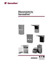
AC Disconnects<br />
Features<br />
• Ample wiring space<br />
• Rugged design<br />
• Numerous knockouts<br />
• Raised mounting embosses<br />
• Copper conductors<br />
• Pullout switch*<br />
• Fuse holder**<br />
• Removable door<br />
• Meets national electrical code<br />
requirements<br />
Benefits<br />
• The larger enclosure allows for ample<br />
wiring space.<br />
• Manufactured with powder coated G90<br />
galvanized steel for fade, scratch <strong>and</strong><br />
corrosion resistance.<br />
• All (6) knockouts are easy to remove.<br />
The sidewall knockouts provide access<br />
from the sides of the device. Every<br />
knockout has 1/2”, 3/4” <strong>and</strong> 1”<br />
provisions.<br />
• (4) Raised mounting embosses keep<br />
the unit away from the wall, preventing<br />
dirt build-up. The upper mounting hole<br />
is shaped to be used as a hanger.<br />
• Copper current carrying part allows for<br />
a cooler, longer lasting operation.<br />
• The pullout switch design allows you<br />
to safely <strong>and</strong> easily de-energize the<br />
load terminals.*<br />
• The easily removable door makes it<br />
possible to wire the device with<br />
absolutely no interference.<br />
• The easy to remove pullout securely<br />
holds the fuses in place. The fuse<br />
holder design allows you to safely <strong>and</strong><br />
easily de-energize the load terminals<br />
without the need to remove the<br />
fuses.**<br />
• <strong>Siemens</strong> air conditioning disconnects<br />
provide the ideal means to comply to<br />
articles 440-14 <strong>and</strong> 110-3(b) of the 1999<br />
National Electrical Code.<br />
*Non-fused only<br />
**Fused only<br />
Fused Disconnect<br />
Non-Fused<br />
Disconnect<br />
Disconnects by <strong>Siemens</strong><br />
UL Listed, NEMA Type 3R Enclosure 240 Volts<br />
ServiceFirst <strong>Catalog</strong> Ampere Maximum Disconnect Std.<br />
Item # Number Rating Horsepower Type Pkg.<br />
SWT02385 WN2060TR 60 10 Non-Fusible Pullout 6<br />
UL Listed, NEMA Type 3R Enclosure 240 Volts<br />
ServiceFirst <strong>Catalog</strong> Ampere Maximum Fuse 1 Std.<br />
Item # Number Rating Horsepower Class Pkg.<br />
SWT02386 WF2030TR 2 30 3 H 6<br />
SWT02387 WF2060TR 2 60 10 H 6<br />
1. Fuses not included.<br />
2. Service Entrance rated.<br />
RSP-PRC003-EN<br />
21
Features <strong>and</strong><br />
Applications<br />
Definite Purpose<br />
Contactors<br />
Definite Purpose Contactors<br />
Centurion 2000, Premium Line<br />
• 25-210A<br />
• 210 FLA 60 Hz 600VAC Max<br />
• Compact Size<br />
• Interchangeable Mounting<br />
• Snap-On Electrical/Mechanical<br />
Interlocks<br />
• Oversize Lugs Available on 25A <strong>and</strong><br />
30A<br />
• Sems Screws Available on 25A, 30A<br />
<strong>and</strong> 40A<br />
• Binding Head Screws Optional on<br />
40-60A<br />
• Class H Coil Insulation<br />
• Optional Electronic Timers, Surge<br />
Suppressors <strong>and</strong> Step Down DC Coil<br />
Drivers Built into Coils<br />
• Snap-On Electronic Accessories<br />
• Meets ARI-780, UL <strong>and</strong> CSA St<strong>and</strong>ards<br />
Application<br />
The <strong>Furnas</strong> Centurion 2000 offers a high<br />
new st<strong>and</strong>ard in definite purpose control.<br />
The largest, most complete line of<br />
definite purpose motor controls in the<br />
industry, it is ideal for many applications<br />
including:<br />
HVAC<br />
Welding<br />
Refrigeration Lighting<br />
Elevators Pools & Spas<br />
Hoists & Cranes<br />
Food Processing<br />
Data Processing<br />
Pumps & Compressors<br />
When used with an appropriate pilot<br />
device they can provide either low<br />
voltage protection or low voltage<br />
release. These controls have been<br />
designed with a low drop out voltage<br />
making them ideal for air conditioning,<br />
heating <strong>and</strong> refrigeration applications.<br />
Construction<br />
The Centurion 2000 was designed to be<br />
a tougher, more compact, more versatile<br />
<strong>and</strong> quieter contactor than ever before.<br />
Product features include:<br />
Tougher Materials – The housing <strong>and</strong> all<br />
other non-metal body parts are made of<br />
bulk molding compound for greater<br />
strength <strong>and</strong> durability.<br />
Compact – Space saving dimensions<br />
allow for smaller panels <strong>and</strong> more<br />
wiring room.<br />
Straight Thru Wiring – Line terminals<br />
are located at the top <strong>and</strong> load terminals<br />
at the bottom. This construction<br />
eliminates looping wires around the<br />
control <strong>and</strong> reduces wiring costs.<br />
Interchangeable Mounting – The<br />
combination of multiple mounting holes<br />
<strong>and</strong> slots allows these contactors to be<br />
fastened onto panels <strong>and</strong> provide<br />
interchangeable mounting with many<br />
competitive contactors.<br />
25A, 30A, 40A 50A, 60A 75A, 90A<br />
22 RSP-PRC003-EN
Features <strong>and</strong><br />
Applications<br />
Definite Purpose<br />
Contactors<br />
Definite Purpose Contactors<br />
Centurion 2000, Premium Line<br />
• 25-210A<br />
• 210 FLA 60 Hz 600VAC Max<br />
Terminals – Line <strong>and</strong> load terminals are<br />
supplied with pressure connectors. Pilot<br />
control wires can attach to the line<br />
terminals by using integral auxiliary<br />
connections. Oversize lugs are st<strong>and</strong>ard<br />
on 40A <strong>and</strong> optional on 25A <strong>and</strong> 30A.<br />
You also have a choice of three terminal<br />
styles – box lug, binding head screws, or<br />
sems clamp.<br />
Coils – Class H high temperature<br />
insulated coils are st<strong>and</strong>ard on 25A-60A<br />
contactors. Vibration has been<br />
minimized by cushioning the coil <strong>and</strong> the<br />
enclosed construction reduces the<br />
possibility of failure due to<br />
contaminants. Coils on 25-60A are<br />
equipped with combination pressure<br />
<strong>and</strong> quick connect terminals. Electronic<br />
timers, surge suppressors or DC coil<br />
drivers are available built into the coils.<br />
This option simplifies wiring <strong>and</strong> allows<br />
less panel space to be used.<br />
Coils on 75A-210A contactors are<br />
encapsulated in a moisture proof epoxy.<br />
Some coils are equipped with<br />
combination pressure <strong>and</strong> quick connect<br />
terminals. Connections are made by<br />
inserting the stripped wire under the<br />
screw head <strong>and</strong> tightening or by<br />
pressing on a quick connector.<br />
Single voltage coils are st<strong>and</strong>ard for all<br />
popular voltages <strong>and</strong> frequencies. Dual<br />
voltage, 120/240 or 240/480 volts, 50-60<br />
Hz coils are available at an additional<br />
cost. Dual voltage coils are st<strong>and</strong>ard on<br />
the 120A - 210A contactors.<br />
The 75A <strong>and</strong> 90A devices are also<br />
available with DC magnet <strong>and</strong> coil as an<br />
optional feature. Magnet <strong>and</strong> coil<br />
assemblies are available for 6, 12, 24, 32,<br />
115 <strong>and</strong> 230VDC.<br />
Magnet – The magnet is constructed of<br />
laminations of silicon steel. A shading<br />
coil insures a positive sealing of the<br />
armature.<br />
Snap-On Accessories – Two snap-on<br />
electrical interlocks provide up to four<br />
SPST or SPDT circuits. Interlocks snap<br />
on each side <strong>and</strong> are optional. An<br />
optional mechanical interlock is also<br />
available. Other accessories such as<br />
timers, coil snubbers, coil drivers <strong>and</strong><br />
others provide versatile, exp<strong>and</strong>able<br />
control.<br />
Auxiliary Electrical Interlocks – <strong>Furnas</strong><br />
supplies one or two interlocks as a<br />
factory modification or for field<br />
installation on 75A <strong>and</strong> 90A contactors.<br />
Four auxiliary interlocks can accept<br />
120A-210A contactors.<br />
Available with either normally open or<br />
normally closed contacts, they are<br />
mounted in a molded guide <strong>and</strong> held in<br />
place with a single screw.<br />
Arc Box – Molded of a glass filled<br />
thermoset material, it withst<strong>and</strong>s<br />
tracking <strong>and</strong> prevents flash over.<br />
Cross Arm – This rugged, molded part<br />
resists the stresses of high temperatures<br />
<strong>and</strong> impacts.<br />
Contacts – Made of silver cadmium<br />
oxide that resists welding, arc erosion<br />
<strong>and</strong> mechanical wear, these critical<br />
components are bonded to rugged<br />
backing material.<br />
REFERENCE LITERATURE<br />
Instruction Sheets <strong>and</strong> Replacement Parts<br />
Size Instruction Replacement<br />
FLA Sheet Parts<br />
25, 30, 40 PM-60.1 42-GBF<br />
50,60 PM-60.1 42-GDF<br />
75, 90 PM-60.1 42-GFE<br />
120, 150 PM-60.1 16-GHF<br />
210 PM-60.1 42-GJB<br />
120A, 150A<br />
210<br />
RSP-PRC003-EN<br />
23
Features <strong>and</strong><br />
Applications<br />
Definite Purpose<br />
Contactors<br />
Definite Purpose Contactors<br />
St<strong>and</strong>ard Line<br />
• 20-40 FLA 60 Hz 600VAC Max<br />
• For Contactors Thru 210 FLA, see<br />
Centurion 2000 Premium line.<br />
Single Pole<br />
• Compact Size<br />
• Straight Thru Wiring<br />
• Long Life<br />
• Non Tracking Contact Board<br />
• Interchangeable Mounting Base<br />
• Quick Connect Terminals<br />
• Weld Resistant Contacts<br />
• UL File E14900<br />
• CSA File LR6535 <strong>and</strong> 42531<br />
• TUV/VDE Approved – Contact Factory<br />
Application<br />
<strong>Furnas</strong> compact definite purpose<br />
contactors are designed for controlling<br />
air conditioning, heating, welding, data<br />
processing <strong>and</strong> refrigeration equipment.<br />
They provide reliable full voltage control<br />
of compressor motors <strong>and</strong> electric<br />
heating loads. When used with an<br />
appropriate pilot device they can provide<br />
either low voltage protection or low<br />
voltage release. These controls have<br />
been designed with a low drop out<br />
voltage making them ideal for air<br />
conditioning, heating <strong>and</strong> refrigeration<br />
applications.<br />
Construction<br />
Compact – Space saving dimensions<br />
allow for smaller panels <strong>and</strong> more wiring<br />
room.<br />
Straight Thru Wiring – Line terminals are<br />
located at the top <strong>and</strong> load terminals at<br />
the bottom. This construction eliminates<br />
looping wires around the control <strong>and</strong><br />
reduces wiring costs.<br />
Mounting – Contactors are designed for<br />
mounting on a vertical service. Side by<br />
side grouping is possible since all<br />
terminals are front accessible <strong>and</strong><br />
isolated from adjacent controls by<br />
molded barriers.<br />
Interchangeable Mounting – The<br />
combination of multiple mounting holes<br />
<strong>and</strong> slots allows these contactors to be<br />
fastened onto panels <strong>and</strong> provide<br />
interchangeable mounting with many<br />
competitive contactors.<br />
Terminals – Line <strong>and</strong> load terminals are<br />
supplied with pressure connectors. Pilot<br />
control wires attach to the line terminals<br />
by using integral auxiliary connections.<br />
2 Pole<br />
24 RSP-PRC003-EN
Selection<br />
Procedure<br />
Definite Purpose<br />
Contactors<br />
Definite Purpose Contactors<br />
Centurion 2000, Premium Line<br />
• 25-210A<br />
• 210 FLA 60 Hz 600VAC Max<br />
25A, 30A, 40A 50A, 60A 75A, 90A<br />
Non<br />
ServiceFirst<br />
120V 240V 277V 480V 600V Inductive Poles Coil<br />
Item # Mfg. # FLA Hp LRA Hp LRA Hp LRA Hp LRA Hp Amps Phase Voltage<br />
60 FLA 60 Hz 600VAC Max<br />
CTR01140 42AF35AJ 25 - 150 5 - - 125 7-1/2 100 7-1/2 35 3,3 Ph 24<br />
CTR01362 42AF35AJ w/lugs<br />
CTR01141 42AF35AF 110-120<br />
CTR01363 42AF35AF w/lugs<br />
CTR01142 42AF35AG 200-208<br />
CTR01364 42AF35AG w/lugs<br />
CTR01730 42BF15AJ 30 2 180 5 - - 150 - 120 - 40 2,1 Ph 24<br />
CTR01731 42BF15AF 110-120<br />
CTR01732 42BF15AG 200-208<br />
CTR01149 42BF35AJ 30 - 180 7-1/2 - - 150 10 120 10 40 3,3 Ph 24<br />
CTR01365 42BF35AJ w/lugs<br />
CTR01150 42BF35AF 110-120<br />
CTR01366 42BF35AF w/lugs<br />
CTR01151 42BF35AG 200-208<br />
CTR01367 42BF35AG w/lugs<br />
CTR01158 42CF15AJ 40 3 240 7-1/2 - - 200 - 160 - 50 2,1 Ph 24<br />
CTR01159 42CF15AF 110-120<br />
CTR01160 42CF15AG 200-208<br />
CTR01161 42CF35AJ 40 - 240 10 - - 200 15 160 15 50 3,3 Ph 24<br />
CTR01162 42CF35AF 110-120<br />
CTR01163 42CF35AG 200-208<br />
CTR01164 42CF25AJ 40 - 240 10 - - 200 15 160 15 50 4,3 Ph 24<br />
CTR01165 42CF25AF 110-120<br />
CTR01166 42CF25AG 200-208<br />
CTR01167 42DF35AJ 50 - 300 15 - - 250 25 200 25 63 3,3 Ph 24<br />
CTR01168 42DF35AF 110-120<br />
CTR01169 42DF35AG 200-208<br />
CTR01170 42EF35AJ 60 - 360 20 - - 300 30 240 30 75 3,3 Ph 24<br />
CTR01171 42EF35AF 110-120<br />
CTR01172 42EF35AG 200-208<br />
150 FLA 60Hz 600VAC Max<br />
CTR00534 42FE35AJ106 75 - 450 25 - - 375 40 300 40 93 3,3 Ph 24<br />
CTR00535 42FE35AF106 110-120<br />
CTR00536 42FE35AG106 200-208<br />
CTR00538 42GE35AF106 90 - 540 30 - - 450 50 360 50 120 3,3 Ph 110-120<br />
CTR00539 42GE35AG106 200-208<br />
CTR00540 42HF35AA 120 - 720 - - - 600 - 480 - 150 3,3 Ph 110-120/220-240<br />
CTR00541 42HF35AC 220-240/440-480<br />
CTR00542 42IF35AA 150 - 900 - - - 750 - 600 - 160 3,3 Ph 110-120/220-240<br />
CTR00543 42IF35AC 208-240/480<br />
210 FLA 60Hz 600VAC Max<br />
CTR01843 3RT1064-6AF36 225 75 150 3,3 pH 120<br />
CTR01844 3RT1064-6AP36 225 75 150 3,3 pH 240<br />
CTR01845 3RT1064-6AR36 225 75 150 3,3 pH 480<br />
*Terminal Kit for 3RT106 225 A contactor - use TER01072 (3RT1966-4G). Kit includes 3 terminals for line or load. 2 required per 3RT106 contactor.<br />
RSP-PRC003-EN<br />
25
Selection<br />
Procedure<br />
Definite Purpose<br />
Contactors<br />
Definite Purpose Contactors<br />
Centurion 2000 Accessories<br />
• Field Modification Kits<br />
• Snap-On Side Mounted Auxiliary Interlocks<br />
ServiceFirst Contactor Interlock<br />
Item # Mfg. # Description Class FLA Contacts<br />
SWT01730 49D36098001 42 25-60 1 SPDT<br />
SWT01732 49ACRO 1NO<br />
SWT01733 49ACRC Auxiliary 1NC<br />
SWT01731 49D36098003 Interlocks 2 SPDT<br />
SWT00531 49D22125001 Auxiliary 42 75-90 NO<br />
SWT00532 49D22125002 Interlocks NC<br />
SWT00529 49CE42SPDT SPDT<br />
SWT00533 49D54682NO Auxiliary 42 120-150 NO<br />
SWT00534 49D54682NC Interlocks NC<br />
SWT00535 3RH1921-1EA11 Auxiliary 3RT106 225 NO & NC (First Side)<br />
SWT00536 3RH1921-1KA11 Interlocks NO & NC (Second Side)<br />
Mechanical Interlock<br />
KIT01048 49D70035001 Mech. Interlock 42 25-60<br />
26 RSP-PRC003-EN
Selection<br />
Procedure<br />
Definite Purpose<br />
Contactors<br />
Definite Purpose Contactors<br />
Centurion 2000 Accessories<br />
• Replacement Parts<br />
• AC Coils<br />
Third<br />
Fourth<br />
ServiceFirst Character of Character of<br />
Item # Mfg. # Cat. No. Cat. No. Volts 60 Hz<br />
Class 42<br />
COL08309 75D70233J A,B,C,D,E F 24<br />
COL08310 75D70233F 110-120<br />
COL08311 75D70233D 200-208<br />
COL08312 75D70233G 208-240<br />
COL08313 75D70233L 277<br />
COL08314 75D70233H 440-480<br />
COL08315 75D70233E 550-600<br />
COL03601 75D56630J B,C,D,E E 24<br />
COL03602 75D56630F 110-120<br />
COL03603 75D56630G 208-240<br />
COL04043 75D56630L 277<br />
COL03604 75D54822H 440-480<br />
COL03705 75D55123E 575<br />
COL03605 75D54772J F,G E 24<br />
COL03606 75D54772F 110-120<br />
COL03607 75D54772G 208-240<br />
COL04094 75D54772L 277<br />
COL03608 75D54772H 440-480<br />
COL03706 75D54772E 550-600<br />
COL03609 75D73251A H,I F 110-120/220-240<br />
COL04097 75D73251D 200-208<br />
COL04045 75D73251L 277<br />
COL03610 75D73251C 220-240/440-480<br />
COL03611 D71628031 J B 110-120/220-240<br />
COL04098 D71628048 208<br />
COL03612 D71628032 220-240/440-480<br />
COL03707 D71628033 550-600<br />
COL11208 3RT1065-5AF31 110-127<br />
COL11209 3RT1065-5AM31 200-220<br />
COL11210 3RT1065-5AP31 220-240<br />
COL11211 3RT1065-5AU31 240-277<br />
COL11212 3RT1065-5AR31 440-480<br />
COL11213 3RT1065-5AT31 575-600<br />
• Contact Kits<br />
Class 42<br />
KIT01223 75EF42 F E<br />
KIT01234 75GE42 G E<br />
KIT01235 75HF14 H F<br />
KIT01236 75IF14 I F<br />
KIT01237 75JB14 J B<br />
RSP-PRC003-EN<br />
27
Diagrams<br />
Contactors<br />
VA (Nominal)<br />
Volts (Nominal)<br />
Class FLA Watts Inrush Sealed Pick-up Drop-out<br />
Class 42 (2P-3P) 25-40 2.5 52 6.2 80% 50%<br />
Class 42 (4P) 25-40 4.2 91 15.6 80% 50%<br />
Class 42 (2P-3P) 50-60 4.2 91 15.6 80% 50%<br />
Class 42 (2P-3P) 75-90 13.5 200 31 85% 53%<br />
Class 42 (2P-3P) 120, 150 14 310 26 85% 50%<br />
Class 42, 25-40A 2, 3 Pole<br />
Third Mtg Mtg Max Approx<br />
Size Character Outline Dimensions Dimensions Screw Wire Ship Wt Ref<br />
FLA of Cat No Poles A B C C1 D D1 E G Size Lbs Dwg<br />
Open 25-30 A, B 3 3 31 /32 2 1 /4 2 7 /8 – 3 1 /8 3 1 /4 1 13 /16 10 8 1 1 /2 D70182<br />
Type 40 C 3 3 31 / 32<br />
2 1 / 4<br />
2 7 / 8<br />
– 3 1 / 8<br />
3 1 / 4<br />
1 13 / 16<br />
10 2 1 1 / 2<br />
D70182<br />
28 RSP-PRC003-EN
Diagrams<br />
Contactors<br />
Class 42, 25-40A 4 Pole<br />
3 5 /8<br />
Class 42, 50A, 60A 3 Pole<br />
Third Mtg Mtg Max Approx<br />
Size Character Outline Dimensions Dimensions Screw Wire Ship Wt Ref<br />
FLA of Cat No Poles A B C D D1 E G Size Lbs Dwg<br />
Open 25-30 A, B 4 3 31 /32 2 7 /8 2 7 /8 3 1 /8 3 1 /4 2 1 /4 10 8 1 1 /2 D70184<br />
Type 40 C 4 3 31 /32 2 7 /8 2 7 /8 3 1 /8 3 1 /4 2 1 /4 10 2 2 D70184<br />
50-60 D, E 3 4 1 /16 2 7 /8 3 1 /16 3 1 /8 3 1 /4 2 1 /4 10 2 1 1 /2 D70183<br />
RSP-PRC003-EN<br />
29
Diagrams<br />
Contactors<br />
Class 42, 75A, 90A 3 Pole<br />
With Two<br />
Electrical Innerlocks<br />
Front<br />
Side<br />
Mounting Hole Pattern<br />
3RT, 225A 3 Pole<br />
Class 42, 120A, 150A 3 Pole<br />
Third Mtg Mtg Max Approx<br />
Size Character Outline Dimensions Dimensions Screw Wire Ship Wt<br />
FLA of Cat No A B C D E G Size Lbs<br />
Open 75 F 5 3 /16 4 4 3 /4 4 5 /8 2 7 /8 10 1/0 3½<br />
Type 90 G 5 3 /16 4 4 3 /4 4 5 /8 2 7 /8 10 1/0 3½<br />
120 H 6 5 /8 4 1 /2 5 9 /16 6 5 /16 1 7 /16 ¼ 3/0 6¼<br />
150 I 6 5 /8 4 1 /2 5 9 /16 6 5 /16 1 7 /16 ¼ 3/0 6¼<br />
Dimensions for reference, not for construction. Third character of catalog number identifies contactor rating.<br />
30 RSP-PRC003-EN
Selection<br />
Procedure<br />
Contactors<br />
Definite Purpose Contactors<br />
St<strong>and</strong>ard Line<br />
• Class 45<br />
Single Pole<br />
2 Pole<br />
Non<br />
ServiceFirst 120V 240V 277V 480V 600V Inductive Poles Coil<br />
Item # Mfg. # FLA Hp LRA Hp LRA Hp LRA Hp LRA Hp Amps Poles Voltage<br />
40 FLA 60 Hz 600VAC Max<br />
CTR01134 45CG10AJA 20 - 120 - 110 - 100 - 80 - 25 1 24<br />
CTR01135 45CG10AFA 110-120<br />
CTR01136 45CG10AGA 208-240<br />
CTR01137 45CG20AJ 20 - - - 120 - 100 - 80 - 30 2 24<br />
CTR01138 45CG20AF 110-120<br />
CTR01139 45CG20AG 208-240<br />
CTR01359 45CG20AL 277<br />
CTR01143 45EG10AJA 30 - 180 - 180 - 150 - 120 - 40 1 24<br />
CTR01144 45EG10AFA 110-120<br />
CTR01145 45EG10AGA 208-240<br />
CTR01146 45EG20AJ 30 - - - 180 - 135 - 110 - 40 2 24<br />
CTR01147 45EG20AF 110-120<br />
CTR01148 45EG20AG 208-240<br />
CTR01360 45EG20AL 277<br />
CTR00736 45FG10ALA 35 - 180 - 180 - 150 - 120 - 50 1 277<br />
CTR01152 45GG10AJA 40 - 200 - 200 - 160 - 140 - 55 1 24<br />
CTR01153 45GG10AFA 110-120<br />
CTR01154 45GG10AGA 208-240<br />
CTR01155 45GG20AJ 40 - - - 200 - 135 - 110 - 55 2 24<br />
CTR01156 45GG20AF 110-120<br />
CTR01157 45GG20AG 208-240<br />
CTR01361 45GG20AL 277<br />
RSP-PRC003-EN<br />
31
Selection<br />
Procedure<br />
Contactors<br />
Replacement Parts Series 31 Wholesale Contactors<br />
• AC Coils<br />
ServiceFirst<br />
Volts<br />
Item # Mfg. # Amps Poles 60 Hz<br />
Series 31<br />
COL03601 75D56630J 25, 30 & 40 1, 2 & 3 24<br />
COL03602 75D56630F 110-120<br />
COL03603 75D56630G 208-240<br />
COL04043 75D56630L 277<br />
COL03604 75D54822H 440-480<br />
COL03705 75D55123E 575<br />
• Contact Kits<br />
Series 31<br />
KIT01223 75FE42 75<br />
KIT01234 75GE42 90<br />
KIT01235 75HF14 120<br />
KIT01236 75IF14 150<br />
KIT01237 75JB14 210<br />
• Box Lugs & Quick Connects<br />
TER00268 75L108694 30 3<br />
TER00269 75L108695 Series 31 Quick Cnt<br />
• Auxiliary Switches<br />
SWT00533<br />
SWT00534<br />
SWT00535<br />
SWT00536<br />
SWT00529<br />
SWT00530<br />
SWT00528<br />
SWT00531<br />
SWT00532<br />
Series 31<br />
SPST-NO 10A/600V fuse on 120 & 150amp<br />
SPST-NC 10A/600V fuse on 120 & 150 amp<br />
SPDT 10A/600V fuse on 210 amp; Right H<strong>and</strong> installation<br />
SPDT 10A/600V fuse on 210 amp; Left H<strong>and</strong> installation<br />
SPDT 10A/250V fuse on 2 pole 40 amp, 3 pole 30 through 90 amp<br />
SPDT .1A/125V (Gold Contacts) fuse on low amp draws 2 pole 40 amp, 3 pole 30 thru 90 amp<br />
(2) SODT 10A/250V fuse on 2 pole 40 amp, 3 pole 30 thru 90 amp<br />
SPST-NO 10A/600V fuse on 2 pole 40 amp, 3 pole 30 thru 90 amp<br />
SPST-NC 10A/600V fuse on 2 pole 40 amp, 3 pole 30 thru 90 amp<br />
32 RSP-PRC003-EN
Diagrams<br />
Contactors<br />
VA (Nominal)<br />
Volts (Nominal)<br />
Class FLA Watts Inrush Sealed Pick-up Drop-out<br />
Class 45 (1P-2P) 20-40 2.6 27 7.3 80% 50%<br />
Dimensions<br />
Class 45, 20-40A 1 Pole<br />
Class 45, 20-40A 2 Pole<br />
Third Mtg Mtg Max Approx<br />
Size Character Outline Dimensions Dimensions Screw Wire Ship Wt Ref<br />
FLA of Cat No Poles A B C C1 D D1 E G Size Lbs Dwg<br />
Open 20-40 C, D, E, F, G 1 3 3 /8 2 1 /16 2 5 /8 2 13 /16 1 5 /8 – 1 5 /8 10 10 1 D36304<br />
Type 20-40 C, D, E, F, G 2 3 3 / 8<br />
2 2 11 / 16<br />
2 13 / 16<br />
1 5 / 8<br />
– 1 5 / 8<br />
10 10 1 D36304<br />
RSP-PRC003-EN<br />
33
Features <strong>and</strong><br />
Applications<br />
Contactors<br />
Magnetic Contactors<br />
Full Voltage<br />
Features<br />
Horsepower rated contactors are<br />
available in NEMA sizes 00 through 6,<br />
plus three <strong>Furnas</strong> M-M motor matched<br />
sizes: 1¾, 2½, <strong>and</strong> 3½. These contactors<br />
can also be used on capacitor <strong>and</strong><br />
transformer switching applications. See<br />
Application Data Section for rating<br />
information.<br />
Auxiliary Equipment<br />
• Field modifications such as auxiliary<br />
electrical interlocks, pilot lights, push<br />
buttons, selector switches <strong>and</strong> fuse<br />
blocks for low voltage pilot control are<br />
available to meet particular application<br />
requirements.<br />
• Normally open or normally closed<br />
power pole kits are available for sizes<br />
0 through 1¾.<br />
• A full line of replacement parts is<br />
available including contact kits, coils<br />
<strong>and</strong> overload relays.<br />
• Rugged Industrial Design<br />
• Dual Voltage, Dual Frequency Coils<br />
• Front Removable Auxiliary Interlocks<br />
• Easy Coil Access<br />
• Horsepower Rating<br />
• Resistance Heating kW Ratings<br />
• Lighting Ampere Ratings<br />
• Capacitor <strong>and</strong> Transformer Switching<br />
Applications<br />
• Motor Matched Sizes<br />
• Straight Thru Wiring<br />
• Gravity Dropout<br />
• UL Listed 508 File #E14900<br />
• CSA Certified File #LR6535<br />
Applications<br />
Class 40 industrial magnetic contactors<br />
are designed for electrical loads such as<br />
heating, lighting, transformer <strong>and</strong><br />
capacitor switching <strong>and</strong> AC motor<br />
starting. They control motors already<br />
protected by inherent or other types of<br />
overload devices. Used with appropriate<br />
pilot control, a contactor provides a<br />
choice of undervoltage protection or<br />
release.<br />
Class 40 contactors size 0 thru 6 feature<br />
carefully wound coils encapsulated to<br />
seal out moisture. Encapsulation also<br />
promotes heat transfer <strong>and</strong> resists<br />
electrical, mechanical <strong>and</strong> thermal<br />
stresses.<br />
Coil Data<br />
Inrush<br />
Normal<br />
Class 14 Volts (Open Magnet) (Sealed Magnet)<br />
Size Watts 60Hz Amps VA Amps VA<br />
24 2.63 .37<br />
120 .59 .08<br />
208 .34 .05<br />
00 13.3 240 .305 70 .045 10<br />
277 .25 .03<br />
480 1.49 .02<br />
600 .121 .02<br />
24 9.08 1.04<br />
120 1.82 .21<br />
0 208 1.05 .12<br />
thru 8.6 240 .91 218 .105 25<br />
2½ 27 .79 .090<br />
480 .45 .052<br />
600 .36 .042<br />
24 12.9 1.08<br />
120 2.58 .217<br />
208 1.49 .125<br />
3, 3½ 14 240 1.29 210 .108 26<br />
277 1.12 .094<br />
480 .646 .054<br />
600 .516 .043<br />
120 4.25 .425<br />
208 2.45 .245<br />
240 2.15 .215<br />
4 22 277 1.77 510 .183 51<br />
480 1.08 .112<br />
600 .85 .085<br />
120 12.65 .96<br />
240 6.32 .48<br />
5 63 480 3.16 1518 .24 116<br />
600 2.53 .193<br />
240 1.45 .25<br />
6 40 480 .73 350 .12 60<br />
600 .58 .10<br />
34 RSP-PRC003-EN
Features <strong>and</strong><br />
Applications<br />
Contactors<br />
Magnetic Reversing<br />
Contactors<br />
Full Voltage<br />
• Rugged Industrial Design<br />
• Dual Voltage, Dual Frequency Coils<br />
• Compact Design<br />
• Front Removable Auxiliary Interlocks<br />
• Easy Coil Access<br />
• Straight Thru Wiring<br />
• Gravity Dropout<br />
• UL Listed 508 File #E14900<br />
• CSA Certified File #LR6535<br />
Application<br />
Class 43 industrial magnetic reversing<br />
contactors are designed for across the<br />
line starting of single phase <strong>and</strong><br />
polyphase motors which do not require<br />
overload protection.<br />
These controls are available in NEMA<br />
sizes 00 through 6. In addition to the<br />
usual NEMA starter sizes <strong>Furnas</strong> offers<br />
four exclusive Motor Matched M•M<br />
sizes; 1¾, 2½, 3½ <strong>and</strong> 4½. These half<br />
sizes offer the same rugged, industrial<br />
construction as our NEMA sizes <strong>and</strong><br />
ensure efficient operating performance.<br />
<strong>Furnas</strong> M•M sizes provide a real cost<br />
savings by cutting down on wasteful<br />
over capacity when NEMA sizes exceed<br />
the motor ratings.<br />
Typical applications include use with<br />
machine tools, material h<strong>and</strong>ling<br />
equipment, hoists <strong>and</strong> various<br />
production <strong>and</strong> industrial equipment as<br />
well as dem<strong>and</strong>ing automotive<br />
applications. These controls may also be<br />
used as changeover contactors on<br />
emergency power panels to transfer<br />
from commercial to st<strong>and</strong>by power.<br />
Features<br />
<strong>Furnas</strong> reversing contactors size 0-6<br />
include the following as st<strong>and</strong>ard.<br />
Molded Coil — Magnet coils are carefully<br />
wound <strong>and</strong> then sealed in epoxy. Encapsulation<br />
helps seal out moisture,<br />
promotes heat transfer <strong>and</strong> resists<br />
electrical, mechanical <strong>and</strong> thermal<br />
stresses.<br />
Dual Voltage/Frequency — <strong>Furnas</strong><br />
contactors size 0-6 are available with<br />
dual voltage, dual frequency coils <strong>and</strong><br />
are designed to operate on 50/60 Hz.<br />
Field Modifications Kits/Accessories —<br />
All reversing contactors can be modified<br />
in the field with a complete range of<br />
accessories. These include push buttons,<br />
selector switches, pilot lights, auxiliary<br />
electrical interlocks <strong>and</strong> surge<br />
suppressors.<br />
Size 0 through 4<br />
Reversing Contactors<br />
The following features are characteristic<br />
of size 0 through 4.<br />
Gravity Dropout — For added reliability,<br />
the gravity drop out of the armature <strong>and</strong><br />
contacts is assisted by stainless steel<br />
springs which help provide quick,<br />
precise opening of the contacts.<br />
45 Degree, Wedge Action — The 45<br />
degree, wedge action contacts reduce<br />
tracking <strong>and</strong> provide faster arc<br />
quenching. The resulting self cleaning<br />
<strong>and</strong> reduced contact bounce mean<br />
cooler operation <strong>and</strong> longer life for the<br />
silver cadamium oxide contacts.<br />
Terminal Design — Control terminals are<br />
self rising pressure type. Power terminal<br />
points are provided for use with power<br />
factor correction capacitors.<br />
Interlocks — Cross electrical interlocks<br />
prevent the simultaneous energization of<br />
both contactors.<br />
Mechanical Interlock — A mechanical<br />
interlock is provided to prevent both<br />
contactors from closing at the same<br />
time.<br />
Size 5 through 6<br />
Reversing Contactors<br />
In addition to the st<strong>and</strong>ard features, size<br />
5 through 6 reversing contactors<br />
incorporate many of the additional<br />
features listed for size 0 through 4<br />
including side mounting auxiliary<br />
interlocks. <strong>Furnas</strong> size 5 through 6<br />
reversing contactors use the reliable<br />
vertical lift magnetic action which has<br />
proven long life <strong>and</strong> trouble free<br />
performance.<br />
RSP-PRC003-EN<br />
35
Selection<br />
Procedure<br />
Contactors<br />
Heavy-Duty Full Voltage Non-Reversing<br />
Ordering Instructions<br />
• See Field Modification Kits.<br />
• See 380 Volt 50 Hertz information.<br />
• See Replacement Parts.<br />
• See Dimensions.<br />
• See Wiring Diagrams.<br />
• See Application Data<br />
Coil Table<br />
60 Hz Voltage Letter<br />
110–120/220–240 A<br />
For other voltages <strong>and</strong> frequencies, coil<br />
may be purchased separately.<br />
*120V coil<br />
3 Pole, 3 Phase<br />
Max HP<br />
Cont<br />
ServiceFirst 200 230 460 575 NEMA Half Amp<br />
Item # Mfg. # Volts Volts Volts Volts Size Size Rating<br />
CTR01647 40BG32AA 1 1 /2 1 1 /2 2 2 0 — 9<br />
CTR01648 40CP32AA 3 3 5 5 0 — 18<br />
CTR01649 40DP32AA 7 1 /2 7 1 /2 10 10 1 — 27<br />
CTR01655 40EP32AA 10 10 15 15 — 1 3 /4 40<br />
CTR01650 40FP32AA 10 15 25 25 2 — 45<br />
CTR01656 40GP32AA 15 20 30 30 — 2 1 /2 60<br />
CTR01651 40HP32AA 20 30 50 50 3 — 90<br />
CTR01657 40IP32AA 30 40 75 75 — 3 1 /2 115<br />
CTR01652 40JG32AA 40 50 100 100 4 — 135<br />
CTR01653 40LG32A* 75 100 200 200 5 — 270<br />
CTR01654 40MG32A* 150 200 400 400 6 — 540<br />
36 RSP-PRC003-EN
Selection<br />
Procedure<br />
Contactors<br />
Heavy-Duty Full Voltage Non-Reversing<br />
Ordering Instructions<br />
• See Field Modification Kits.<br />
• For 380 Volt 50 Hertz information, see<br />
Application Data Section.<br />
• See Replacement Parts.<br />
• Other information see Application Data<br />
Section.<br />
• See Dimensions.<br />
• See Wiring Diagrams.<br />
• See Application Data<br />
Coil Table<br />
60 Hz Voltage Letter<br />
110–120/220–240 A<br />
For other voltages <strong>and</strong> frequencies, coil<br />
may be purchased separately.<br />
2 Pole, 1 Phase<br />
Max. HP<br />
Cont<br />
ServiceFirst 200 230 NEMA Half Amp<br />
Item # Mfg. # Volts Volts Size Size Rating<br />
CTR01658 40BG12AA 1<br />
/3 1 00 — 9<br />
CTR01691 40CP12AA 1 2 0 — 18<br />
CTR01660 40DP12AA 2 3 1 — 27<br />
CTR01661 40EP12AA 3 5 1P — 35<br />
CTR01662 40FP12AA 3 7 1 /2 2 — 45<br />
CTR01667 40GP12AA 5 10 — 2 1 /2 60<br />
CTR01689 40HP12AA 7 1 /3 15 3 — 90<br />
CTR01668 40IP12AA — — — 3 1 /2 115<br />
CTR01664 40JG12AA — — 4 — 135<br />
RSP-PRC003-EN<br />
37
Selection<br />
Procedure<br />
Contactors<br />
Heavy-Duty Full Voltage Reversing<br />
Ordering Instructions<br />
• See Field Modification Kits.<br />
• For 380 Volt 50 Hertz information, see<br />
Application Data Section.<br />
• See Dimensions.<br />
• See Wiring Diagrams.<br />
Coil Table<br />
60 Hz Voltage Letter<br />
110–120/220–240 A<br />
120 F<br />
For other voltages <strong>and</strong> frequencies, coil<br />
may be purchased separately.<br />
Max. HP<br />
Cont<br />
ServiceFirst 200 230 460 575 NEMA Half Amp<br />
Item # Mfg. # Volts Volts Volts Volts Size Size Rating<br />
CTR01669 43BG32AA 1 1 /2 1 1 /2 2 2 00 — 9<br />
CTR01670 43CP32AA 3 3 5 5 0 — 18<br />
CTR01671 43DP32AA 7 1 /2 7 1 /2 10 10 1 — 27<br />
CTR01677 43EP32AA 10 10 15 15 — 1 3 /4 40<br />
CTR01672 43FP32AA 10 15 25 25 2 — 45<br />
CTR01678 43GP32AA 15 20 30 30 — 2 1 /2 60<br />
CTR01673 43HP32AA 25 30 50 50 3 — 90<br />
CTR01679 43IP32AA 30 40 75 75 — 3 1 /2 115<br />
CTR01674 43JG32AA 40 50 100 100 4 — 135<br />
CTR01675 43LG32AF 75 100 200 200 5 — 270<br />
CTR01676 43MG32AF 100 200 400 400 6 — 540<br />
38 RSP-PRC003-EN
Selection<br />
Procedure<br />
Contactors<br />
Heavy Duty <strong>Controls</strong> Modifications<br />
Field Modification Kits<br />
Auxiliary Contact Kits<br />
ServiceFirst Controller Enclosure<br />
Item # Mfg. # Description Class Size Type<br />
CTR01626 49AB10 Auxiliary Contact NEMA A600 NO 0–4<br />
CTR01627 49AB01 Front Mtg NC 14,22 All<br />
SPST 40,43<br />
CTR01932 49AB11 1 NO, 1 NC<br />
CTR01933 49AB20 2 NO<br />
CTR01628 3TY7561-1K4 1-NO/1-NC Auxiliary 4 1 /2, 5 —<br />
Cont Block-Left 14,22<br />
CTR01629 3TY7561-1L4 1-NO/1-NC Auxiliary 40,43<br />
Cont Block-Right<br />
Heavy Duty <strong>Controls</strong> Modifications<br />
Non-Combination Enclosure Kits<br />
Non-Reversing Contactors<br />
ServiceFirst<br />
Item # Mfg. # Size<br />
KIT06558 49EC14EB110705R 00-1¾<br />
KIT06559 49EC14GB140807R 2-2½<br />
KIT06560 49EC14IB201208R 3-3½<br />
KIT06561 49EC14JB251409R 4<br />
Type 1<br />
Reversing Contactors<br />
ServiceFirst<br />
Item # Mfg. # Size<br />
KIT06560 49EC14IB201208R 00-2½<br />
KIT06561 49EC14JB251409R 3-4<br />
Pilot Devices<br />
ServiceFirst Controller Enclosure<br />
Item # Mfg. # Description Class Size Type<br />
Push Buttons SWT02666 49SAPB5 Start, Stop 14, 40 00-3 1 /2 1<br />
SWT02667 49SAP05 14, 40 4-8 1<br />
Selector Switches SWT02542 49SASB1 H<strong>and</strong>-Off-Auto 14, 40 00-3 1 /2 1<br />
SWT02668 49SAS01 14, 40 4-8 1<br />
RSP-PRC003-EN<br />
39
Selection<br />
Procedure<br />
Contactors<br />
Miscellaneous Kits<br />
ServiceFirst Controller Enclosure<br />
Item # Mfg. # Description Class Size Type<br />
CTR01634 49CCF22H Mechanical 0–1<br />
CTR01635 49EEF22H Interlock 1 3/4<br />
CTR01636 49GGF22H Includes wire 2, 2 1/2<br />
CTR01638 49HHP22H 3, 3 1/2<br />
49JJG22H Horizontal 14, 40 4 Open<br />
CTR01639 49D26344 Surge Surge Suppressor for 120V AC<br />
Suppressor coil. Limits transient voltage 14,22 0–31/2 All<br />
produced by the coil to 220% 40,43<br />
maximum peak line volts.<br />
CTR01640 49SAF0 Auxiliary NO 36A at 600V AC Max 14,22 0–13/4 All<br />
CTR01641 49SAFC Power Pole NC 25A at 600V AC Max 40,43<br />
CTR01642 49SAE Load Side Includes 3 power lugs<br />
Power Take for making extra 14,22 0–1 All<br />
Off Kit connections to the load 40,43<br />
side of the contactor<br />
AC COILS—For Class 14, 22, 40, 43<br />
ServiceFirst<br />
Volts<br />
Item # Mfg. # Size Model 60Hz 50Hz<br />
COI00954 75D73070J 24 24<br />
COI00955 75D73070A 00-2 1/2 110–120/220–240 110/190–220<br />
COI00956 75D73070D F, P 208 —<br />
COI00957 75D73070C R, S (ESP100) 220–240/440–480 190–220/380–440<br />
COI00958 75D73251J 24 24<br />
COI00959 75D73251A 3,3 1/2 110–120/220–240 110/190–220<br />
COI00960 75D73251D F, P 208 —<br />
COI00961 75D73251C R, S (ESP100) 220–240/440–480 190–220/380–440<br />
COI00962 75D70131J 24 24<br />
COI00963 75D70131A 120/220–240 110/190–220<br />
COI00964 75D70131D 4 G, P 208 —<br />
COI00965 75D70131C R, T (ESP100) 220–240/440–480 190–220/380–440<br />
COL03611 D71628031 110–120/220–240 110/190–220<br />
COL04098 D71628048NB 4 B 208 —<br />
COL03612 D71628032NB 220–240/440–480 190–220/380–440<br />
COI00966 D72069031 110–120/220–240 110/190–220<br />
COI00967 D72069047 4 1/2,5 B, F 208 —<br />
COI00968 D72069032 R, S (ESP100) 220–240/440–480 190–220/380–440<br />
D72069045 440–480 380–440<br />
40 RSP-PRC003-EN
Selection<br />
Procedure<br />
Contactors<br />
Contact Kits—Single Pole Stationary <strong>and</strong> Movable Contacts, Contact Spring 1<br />
ServiceFirst<br />
Model<br />
Description Item # Mfg. # Size No of Poles in Kit (4th position in part number)<br />
KIT06542 75AF14 Interlock<br />
N/A (replace contactor) 0 1 G<br />
KIT06543 75BF14 0 F, P<br />
KIT06544 75CF14 0 F, P, S<br />
KIT06545 75DF14 1 1 F, P, S<br />
KIT06546 75EF14 1 3 /4–1P F, P, S<br />
KIT06547 75FF14 2 1 F<br />
KIT06548 75FP14 P, S<br />
KIT06549 75GF14 2 1 /2 1 F<br />
KIT06550 75GP14 P, S<br />
Class 14, 40, 43 KIT06551 75HF14 3 F, P, S<br />
KIT06552 75IF14 3 1 /2 1 F, P, S<br />
KIT06553 75JG14 4 1 G, P, T<br />
KIT06554, KIT01237 75JB14 4 B<br />
KIT06555 75RB14 4 1 /2 1 B, F, S<br />
KIT06556 75KB14 5 1 B, F, S<br />
KIT06557 75MB14 6 1 B, F, S<br />
1<br />
On 3 phase controls, all 3 poles should be replaced— 3 kits required.<br />
RSP-PRC003-EN<br />
41
Diagrams<br />
Contactors<br />
Full Voltage Open Type NEMA Contactor Size 00-6<br />
Figure 1 Figure 2 Figure 3<br />
Open Type<br />
Mtg Mtg Max Approx<br />
3rd Character Outline Dimensions Dimensions 1Screw Wire Ship Wt Ref<br />
Size of Catlog No Fig A B B1 B2 C D D1 E G Size Lbs (Kg) Dwg<br />
00 B 1 3.75 (95) 2.25 (57) 4.50 (114) 5.50 (140) 3.19 (81) 2.38 (60) 2.75 (70) 1.38 (35) 8 (203) 12 2 (1) D29340<br />
0–1 C, D 2 4.31 (110) 3.94 (100) 4.25 (108) 4.75 (121) 3.75 (70) 3.94 (100) 0.19 (5) 1.00 (25) 10 (254) 8 4 (2) D56273<br />
1 3 /4 E 2 4.31 (110) 3.94 (100) 4.25 (108) 4.75 (121) 3.75 (70) 3.94 (100) 0.19 (5) 1.00 (25) 10 (254) 6 4 (2) D56273<br />
2 F 2 4.88 (124) 3.94 (100) 4.25 (108) — 4.00 (102) 4.50 (114) 0.19 (5) 1.00 (25) 10 (254) 4 11 (5) D56274<br />
2 1 /2 G 2 4.88 (124) 3.94 (100) 4.50 (114) — 4.00 (102) 4.50 (114) 0.19 (5) 1.00 (25) 10 (254) 2 11 (5) D56274<br />
3 H 2 6.13 (156) 5.13 (130) 5.50 (140) — 5.06 (129) 5.63 (143) 0.25 (6) 0.75 (19) 0.25 (6) 0 14 (6) D56275<br />
3 1 /2 I 2 6.13 (156) 5.13 (130) 5.50 (140) — 5.06 (129) 5.63 (143) 0.25 (6) 0.75 (19) 0.25 (6) 00 14 (6) D56275<br />
4 J 2 7.81 (198) 5.19 (132) 5.50 (140) — 5.75 (146) 6.56 (167) 0.81 (21) 0.75 (19) 0.5 (13) 250 MCM 15 (7) D70097<br />
4, 5 K,L 3 7.89 (200) 6.30 (160) — — 8.74 (222) 7.09 (180) — 5.12 (130) — 1–500 MCM or — —<br />
2–300 MCM<br />
6 M 3 8.78 (223) 8.62 (219) — — 8.90 (226) 7.87 (200) — 6.69 (170) — 2–500 MCM — —<br />
42 RSP-PRC003-EN
Diagrams<br />
Contactors<br />
Magnetic Reversing Contactors - Class 43<br />
Figure 1 Figure 2<br />
Figure 3<br />
Open Type Horizontal Mounted<br />
Mtg Approx Max<br />
Outline Dimensions Mtg Dimensions Screw Ship Wt Wire<br />
Size Fig A B B1 C C1 D D1 E F G Lbs (Kg) Size Ref Dwg<br />
00 1 2.75 (70) 3.69 (94) 0.50 (13) 3.44 (87) 1.06 (27) 3.25 (83) 2.75 (70) — — 10 4 (2) 12 D29474<br />
0–1 2 7.69 (195) 7.75 (197) 9.25 (235) 3.88 (98) — 7.25 (184) 0.25 (6) 3.63 (92) — 10 8 (4) 8 D73838<br />
1 3 /4 2 7.69 (195) 7.75 (197) 9.25 (235) 3.88 (98) — 7.25 (184) 0.25 (6) 3.63 (92) — 10 8 (4) 6 D73838<br />
2, 2 1 /2 2 8.94 (227) 7.75 (197) 9.25 (235) 4.56 (116) — 8.5 (216) 0.25 (6) 3.63 (92) — 10 13 (6) 2 D73839<br />
3 2 11.44 (291) 10.94 (278) 11.50 (292) 5.19 (132) — 10.75 (273) 0.38 (6) 5.13 (130) — 0.25 33 (15) 0 D74585<br />
3 1 /2 2 11.44 (291) 10.94 (278) 11.50 (292) 5.56 (141) — 10.75 (273) 0.38 (6) 5.13 (130) — 0.25 33 (15) 00 D74585<br />
4 2 8.50 (216) 10.94 (278) 11.50 (292) 6.25 (159) — 7.81 (198) 0.38 (6) 5.13 (130) — 0.25 35 (16) 250 MCM D56955<br />
4, 5 3 18.07 (459) 14.20 (361) — 9.44 (240) — 17.20 (437) — 9.61 (244) — — — —<br />
6 3 11.61 (295) 18.88 (480) 9.45 (240) 10.85 (276) 7.44 (189) 10.44 (265) 10.71 (272) 17.72 (450) 1.18 (30) — — — —<br />
RSP-PRC003-EN<br />
43
Diagrams<br />
Contactors<br />
Heavy Duty Motor Starters <strong>and</strong> Contactors<br />
Dimensions/Enclosures Class 14, 22, 40, 43<br />
Figure 1<br />
Figure 2<br />
Figure 3<br />
Figure 4<br />
NEMA 1 General Purpose Enclosures<br />
Mtg<br />
Approx<br />
Outline Dimensions Mtg Dimensions Screw Conduit Size Ship Wt<br />
Size Fig A B C D E G K1 K2 K3 K4 K5 Lbs (Kg) Ref Dwg<br />
00-1¾ 1 10 31 /32 (279) 6 13 /32 (163) 5 1 /32 (128) 8 7 /32 (209) 4 5 /8 (117) ¼ ½ ½- ¾ ¾-1 — — 10 (5) D68870<br />
2-2½ 2 13 17 /32 (344) 7 31 /32 (202) 6 3 /8 (162) 10¼ (260) 6 (152) ¼ ½-¾ ¾–1 1-1¼ — — 15 (7) D68870<br />
3-3½ 3 19 1 /8 (486) 11 3 /8 (289) 7 11 /16 (195) 15 5 /8 (397) 8¼ (210) ¼ ½-¾ 1-1¼ 1½- 2 — — 26 (12) D68870<br />
4 4 24 7 /8 (632) 13 3 /8 (340) 8 1 /8 (206) 21¾ (552) 9 (229) ¼ ½-¾ 1¼-1½ 2-2½ — — 37 (17) D68870<br />
44 RSP-PRC003-EN
Diagrams<br />
Contactors<br />
Magnetic Contactors <strong>and</strong> Reversing Contactors - Class 40, 43<br />
3 Pole 3 Phase Magnetic Contactors<br />
Size 00 Size 4-5<br />
Size 00<br />
Size 0-4 Size 0-3 1 /2<br />
Single Phase Reversing Contactors - Size 0- 1¾ 3 Phase Reversing Contactors - Size 0-4<br />
3 Phase Reversing Contactors - Size 00<br />
Size 4, 5<br />
RSP-PRC003-EN<br />
45
Features <strong>and</strong><br />
Applications<br />
Overload Relays<br />
ESP100 Solid State Overload<br />
Panel Mounted Class 48<br />
Features<br />
• Broadest Line in the Industry<br />
• NEMA Class 10, 20 <strong>and</strong> 30 Trip Curves<br />
• Trip Free Design<br />
• Solid State Overload<br />
— Phase Loss Protection<br />
— w2% Repeat Trip Accuracy<br />
— Manual Reset<br />
— FLA Adjustment Dial with Wide<br />
Adjustment Range<br />
— Heaterless Design<br />
• UL Listed File #E22655 or Component<br />
Recognized<br />
• CSA Certified File #LR6535<br />
Application<br />
<strong>Furnas</strong> ESP100 solid state overload<br />
relays are self powered, requiring no<br />
separate 120V source to power the<br />
circuit board. They provide phase loss<br />
protection, fewer connection points <strong>and</strong><br />
high repeat trip accuracy which results in<br />
longer motor life <strong>and</strong> cost savings.<br />
NEMA Class 10, 20 <strong>and</strong> 30 trip curves are<br />
available for a variety of applications.<br />
The heaterless construction of these<br />
overloads minimizes energy costs <strong>and</strong><br />
the costs of cabinet ventilation or<br />
cooling. Solid state overloads can be<br />
used at temperatures from –30°C to 70°C<br />
<strong>and</strong> are rated for 50Hz <strong>and</strong> 60Hz<br />
applications.<br />
ESP100 panel mounted overloads can<br />
be used to upgrade existing starter<br />
applications where panel mounted<br />
thermal overloads are used. In addition,<br />
ESP100 overloads can be panel<br />
mounted when used with other types of<br />
controllers, such as DP, IEC contactors,<br />
<strong>and</strong> soft starts.<br />
ESP100 overloads can be used on high<br />
voltage applications, making them ideal<br />
for use with vacuum contactors <strong>and</strong><br />
other high voltage control.<br />
ESP100 overloads can be retrofitted on<br />
existing <strong>Furnas</strong> contactors using the<br />
retrofit plate suffixes or on other br<strong>and</strong>s<br />
using the plates listed in the competitive<br />
retrofit plates table.<br />
Thermal overload relays are used to<br />
protect motors from excessive heat<br />
resulting from sustained motor<br />
overload, too rapid cycling <strong>and</strong> stalled<br />
rotor. The percentage of overload<br />
determines the length of time required<br />
to open the circuit.<br />
Features<br />
The ESP100 solid state overload<br />
provides phase loss protection for the<br />
motor by tripping within three seconds<br />
upon complete loss of one phase of a<br />
three phase motor branch circuit.<br />
Each overload has at least a 2:1 current<br />
adjustment range with the adjustment<br />
dial reading out in full load amps. In<br />
addition to the markings on the dial<br />
there are audible clicks which allow for<br />
extremely fine tuning.<br />
1. NEMA Class 10 for protecting<br />
submersible pump motors,<br />
hermetically sealed refrigeration<br />
motors, etc., trips in less than 10<br />
seconds at 6 times trip current.<br />
2. NEMA Class 20 for protecting<br />
st<strong>and</strong>ard motors trips in less than 20<br />
seconds at 6 times trip current.<br />
3. NEMA Class 30 trips in less than 30<br />
seconds at 6 times trip current.<br />
Note: The trip current in a 40°C ambient<br />
temperature is 125% of the minimum full<br />
load current listed in the heater tables,<br />
unless otherwise shown.<br />
46 RSP-PRC003-EN
Selection<br />
Procedure<br />
Overload Relays<br />
Solid State Overloads <strong>and</strong> Field Modification Kits, Class 48<br />
Ordering Instructions<br />
• Determine overload range for specific<br />
voltage <strong>and</strong> Hp rating.<br />
• To retrofit existing Thermal Innova<br />
Starters with the ESP100 Solid State<br />
Overload Relay add the appropriate<br />
suffix to the end of the catalog number<br />
from the Retrofit Plates table shown<br />
below. Example: 48ASE3M201P.<br />
Additional References<br />
• Trip Curves.<br />
• Dimensions .<br />
• Wiring Diagrams.<br />
Solid State, 3 Phase<br />
Manual Reset<br />
Full Load<br />
ServiceFirst Class 20 Amp Frame 1<br />
Item # Mfg. # Current Range Phase Size<br />
RLY02304 48ASA3M20 0.25–1 3 A<br />
RLY02305 48ASB3M20 0.75–3 3 A<br />
RLY02306 48ASD3M20 2.5–10 3 A<br />
RLY02307 48ASE3M20 9–18 3 A1<br />
RLY02308 48ASF3M20 13–27 3 A1<br />
RLY02309 48ASG3M20 20–40 3 A1<br />
RLY02310 48BSF3M20 13–27 3 B<br />
RLY02311 48BSH3M20 22–45 3 B<br />
RLY02312 48BSJ3M20 30–60 3 B<br />
RLY02313 48BSK3M20 45–90 3 B<br />
RLY02314 48BSL3M20 57–115 3 B<br />
RLY02315 48BSM3M20 67–135 3 B<br />
RLY02316 48BSN3M20 81–162 2 3 B<br />
RLY02317 48ASS3M20 100–210 3 3 A<br />
RLY02318 48ASU3M20 100–270 3 3 A<br />
RLY02319 48ASX3M20 200–540 4 3 A<br />
420–1220 5 3 A<br />
Field Modification Kits<br />
ServiceFirst<br />
Item # Mfg. # Description Frame Size<br />
KIT06529 49ASNO Auxiliary Contact Kit 6 NO Contact All<br />
KIT06530 49ASNC NC Contact All<br />
2<br />
Temperature rating - 20° to 60°C.<br />
3<br />
Requires use of 300:5 Current Transformers–3 of 97CT005.<br />
4<br />
Requires use of 600:5 Current Transformers–3 of 97CT008.<br />
5<br />
Requires use of 1200:5 Current Transformers–3 of 97CT012.<br />
6<br />
Not available on self-reset versions.<br />
RSP-PRC003-EN<br />
47
Diagrams<br />
Overload Relays<br />
Solid State Overload Manual Reset Version<br />
Dimensions “A” Frame—ESP100 Solid State Overload (0.25–10 Amps & 100–1000 Amps 3 Phase, 0.25–16 Amps Single Phase)<br />
Dimensions “A1” Frame—ESP100 Solid State Overload (9–40 Amps), 958 (15–44 Amps), 958L (5.6–40 Amps, 84–528 Amps)<br />
ESP100 Overload<br />
Motor lead Windows<br />
Dimensions “B” Frame—ESP100 Solid State Overload (13–162 Amps), 958 (33–180 Amps), 958L (18–150 Amps)<br />
ESP100 Overload<br />
Motor lead Windows<br />
Manual Reset Wiring Diagram<br />
48 RSP-PRC003-EN
Features <strong>and</strong><br />
Applications<br />
Overload Relays<br />
Special Use Solid State Overloads, Class 958<br />
Features<br />
• Hermetically Sealed Compressor Motor<br />
Applications<br />
• Phase Loss Protection—Trips Within 3<br />
Seconds<br />
• w/2% Repeat Trip Accuracy<br />
• Manual Reset<br />
• “Must Hold Amps” Adjustment Dial<br />
• Wide Adjustment Range<br />
• Self Powered Overload<br />
• Heaterless Design<br />
• Rated 50/60Hz<br />
• –22°F to 159°F (-30°C to 70°C)<br />
• Output Contact Rated NEMA A600,<br />
P600 (10 Amps 600VAC Max, 5 Amps<br />
600VDC Max)<br />
• Self-Reset Output Contact Rated NEMA<br />
B300, P150 (5 Amps, 300VAC Max, 5<br />
Amps, 150VDC Max)<br />
• UL Listed File #E22655<br />
• CSA Certified File #LR6535<br />
Application<br />
<strong>Furnas</strong> special use solid state overload<br />
relays are self powered requiring no<br />
separate source to power the circuit<br />
board. They provide excellent protection<br />
of hermetically sealed compressors <strong>and</strong><br />
artificially cooled motors which require<br />
ambient insensitivity <strong>and</strong> quick trip<br />
response times. Combined with a series<br />
lockout relay, they can provide<br />
unsurpassed protection for hermetically<br />
sealed compressor motors in air<br />
conditioning applications. The<br />
combination of high trip speed, current<br />
adjustment, <strong>and</strong> ease of installation<br />
makes it suitable for these applications.<br />
The trip curves have been custom<br />
tailored to provide proper overload<br />
protection on such loads without<br />
nuisance tripping.<br />
Features<br />
The overload provides phase loss<br />
protection for the motor by tripping in<br />
three seconds upon complete loss of<br />
one phase of a three phase motor<br />
branch circuit.<br />
The heaterless construction of these<br />
overloads minimizes energy costs <strong>and</strong><br />
the costs of cabinet ventilation or<br />
cooling. While thermal overloads require<br />
a heater selection based on a relatively<br />
wide range, these overloads have many<br />
clicks covering the same ampere range<br />
(see Figure 1 below).<br />
Each overload has a 4:1 or 2:1 current<br />
adjustment range with the adjustment<br />
dial reading out must hold amps. Must<br />
trip amps are 112% of the must hold<br />
setting. In addition to the markings on<br />
the dial there are audible clicks which<br />
allow for extremely fine tuning.<br />
Figure 1<br />
A1 Frame 958 Series<br />
B Frame 958 Series<br />
RSP-PRC003-EN<br />
49
Features <strong>and</strong><br />
Applications<br />
Overload Relays<br />
Special Use, Class 948<br />
Reference Literature<br />
• Class 958 Solid State Overload Relays<br />
are functional replacements to Class<br />
948 Electronic Overload Relays. A cross<br />
reference is listed below. See<br />
information on 958 overloads.<br />
948 to 958 Cross Reference<br />
948 Manual-Reset Overloads 958 Manual-Reset Overloads<br />
ServiceFirst Frame Amp ServiceFirst Frame Amp<br />
Item # Mfg. # Size Range Item # Mfg. # Size Range<br />
RLY01636 948AA32A 16–24 RLY02354 958AA32A A1 15–30<br />
“A” Trip 24–36 RLY02355 958BA32A A1 22–44<br />
RLY01638 948CA32A 60Hz “A” Trip 36–54 RLY02356 958CA32A B 33–66<br />
60Hz 52–78 RLY02357 958DA32A B 50–100<br />
76–114 RLY02358 958EA32A B 75–150<br />
RLY02261 948FA32A 112–168 RLY02359 958FA32A B 90–180<br />
RLY02360 948AA32B 16–24 RLY02354 958AA32A A1 15–30<br />
24–36 RLY02355 958BA32A A1 22–44<br />
RLY00863 948CA32B “B” Trip<br />
36–54 RLY02356 958CA32A B 33–66<br />
RLY01957 948DA32B<br />
60Hz<br />
60Hz 52–78 RLY02357 958DA32A B 50–100<br />
OLD00302 948EA32B 76–114 RLY02358 958EA32A B 75–150<br />
RLY02260 948FA32B 112–168 RLY02359 958FA32A B 90–180<br />
RLY01636 948AA32E 16–24<br />
RLY01637 948BA32E<br />
“E” Trip<br />
24–36<br />
RLY01638 948CA32E 60Hz “E” Trip 36–54<br />
RLY01639 948DA32E 60Hz 52–78<br />
Use Class 48 ESP100 ® Overloads (Class 10)<br />
RLY01640 948EA32E 76–114<br />
948FA32E 112–168<br />
948AB32A 16–24 RLY02354 958AA32A A1 15–30<br />
948BB32A “A” Trip 24–36 RLY02355 958BA32A A1 22–44<br />
948CB32A 50Hz “A” Trip 36–54 RLY02356 958CA32A B 33–66<br />
948DB32A 50Hz 52–78 RLY02357 958DA32A B 50–100<br />
948EB32A 76–114 RLY02358 958EA32A B 75–150<br />
948FB32A 112–168 RLY02359 958FA32A B 90–180<br />
RLY01353 948AB32B 16–24 RLY02354 958AA32A A1 15–30<br />
948BB32B<br />
“B” Trip<br />
24–36 RLY02355 958BA32A A1 22–44<br />
50Hz<br />
948CB32B “B” Trip 36–54 RLY02356 958CA32A B 33–66<br />
948DB32B 50Hz 52–78 RLY02357 958DA32A B 50–100<br />
948EB32B 76–114 RLY02358 958EA32A B 75–150<br />
948FB32B 112–168 RLY02359 958FA32A B 90–180<br />
948AB32E 16–24<br />
948BB32E “E” Trip 24–36<br />
948CB32E 50Hz “E” Trip 36–54 Use Class 48 ESP100 ® Overloads (Class 10)<br />
948DB32E 50Hz 52–78<br />
948EB32E 76–114<br />
948FB32E 112–168<br />
50 RSP-PRC003-EN
Features <strong>and</strong><br />
Applications<br />
Overload Relays<br />
Special Use, Class 948 (Continued)<br />
948 to 958 Cross Reference<br />
948 Manual-Reset Overloads 958 Manual-Reset Overloads<br />
ServiceFirst<br />
ServiceFirst<br />
Item # Mfg. # Size Range Item # Mfg. # Size Range<br />
RLY01136 948AA31A 16–24 RLY02379 958AA31A 15–30 A1<br />
RLY01303 948BA31A “A” Trip 24–36 RLY02380 958BA31A 22–44 A1<br />
RLY01140 948CA31A 60Hz 36–54 RLY02381 958CA31A 33–66 B<br />
RLY01135 948DA31A 52–78 RLY02382 958DA31A 50–100 B<br />
RLY01138 948EA31A 76–114 RLY02383 958EA31A 75–150 B<br />
RLY01137 948FA31A 112–168 RLY02384 958FA31A 90–180 B<br />
948AA31B RLY02379 958AA31A 15–30 A1<br />
RLY00531 948BA31B 24–36 RLY02380 958BA31A 22–44 A1<br />
“B” Trip<br />
RLY00450 948CA31B 36–54 RLY02381 958CA31A 33–66 B<br />
60Hz<br />
RLY00453 948DA31B 52–78 RLY02382 958DA31A 50–100 B<br />
RLY00467 948EA31B 76–114 RLY02383 958EA31A 75–150 B<br />
RLY00526 948FA31B 112–168 RLY02384 958FA31A 90–180 B<br />
948AA31E 16–24<br />
948BA31E “E” Trip 24–36<br />
948CA31E 60Hz 36–54 Use Class 48 ESP100 ® Overloads (Class 10)<br />
948DA31E 52–78<br />
948EA31E 76–114<br />
948FA31E 112–168<br />
RLY00552 948AB31A 16–24 RLY02379 958AA31A 15–30 A1<br />
RLY00551 948BB31A “A” Trip 24–36 RLY02380 958BA31A 22–44 A1<br />
RLY00553 948CB31A 50Hz 36–54 RLY02381 958CA31A 33–66 B<br />
RLY00554 948DB31A 52–78 RLY02382 958DA31A 50–100 B<br />
RLY00604 948EB31A 76–114 RLY02383 958EA31A 75–150 B<br />
RLY00606 948FB31A 112–168 RLY02384 958FA31A 90–180 B<br />
948AB31B 16–24 RLY02379 958AA31A 15–30 A1<br />
“B” Trip<br />
948BB31B 24–36 RLY02380 958BA31A 22–44 A1<br />
50Hz<br />
948CB31B 36–54 RLY02381 958CA31A 33–66 B<br />
948DB31B 52–78 RLY02382 958DA31A 50–100 B<br />
948EB31B 76–114 RLY02383 958EA31A 75–150 B<br />
948FB31B 112–168 RLY02384 958FA31A 90–180 B<br />
948AB31E 16–24<br />
948BB31E “E” Trip 24–36<br />
948CB31E 50Hz 36–54 Use Class 48 ESP100 ® Overloads (Class 10)<br />
948DB31E 52–78<br />
948EB31E 76–114<br />
948FB31E 112–168<br />
RSP-PRC003-EN<br />
51
Selection<br />
Procedure<br />
Overload Relays<br />
Special Use Solid State Overloads, Class 958<br />
Ordering Instructions<br />
• See specific Hp rating to determine<br />
overload range.<br />
Additional References<br />
• See Dimensions.<br />
• See Wiring Diagrams.<br />
• See 948 to 958 cross references.<br />
Trip Curve A<br />
Manual Reset<br />
ServiceFirst Amp Frame<br />
Item # Mfg. # Range Size<br />
RLY02354 958AA32AX625 15–30 A1<br />
RLY02355 958BA32AX625 22–44 A1<br />
RLY02356 958CA32AX625 33–66 B<br />
RLY02357 958DA32AX625 50–100 B<br />
RLY02358 958EA32AX625 75–150 B<br />
RLY02359 958FA32AX625 90–180 B<br />
Trip Curve A<br />
Adapter plate for replacing 948C through F styles with 958C through F styles – 49D57124<br />
1<br />
Temperature rating S20° to R60°C.<br />
Field Modification Kits, Class 958<br />
Field Modification Kits<br />
ServiceFirst<br />
Item # Mfg. # Description Frame Size<br />
KIT06529 49ASNO Auxiliary Contact Kit 6 NO Contact All<br />
KIT06530 49ASNC NC Contact All<br />
52 RSP-PRC003-EN
Diagrams<br />
Overload Relays<br />
Solid State Overload Manual Reset Version<br />
Dimensions “A” Frame—ESP100 Solid State Overload (0.25–10 Amps & 100–1000 Amps 3 Phase, 0.25–16 Amps Single Phase)<br />
Dimensions “A1” Frame—ESP100 Solid State Overload (9–40 Amps), 958 (15–44 Amps), 958L (5.6–40 Amps, 84–528 Amps)<br />
ESP100 Overload<br />
Motor Lead Windows<br />
Dimensions “B” Frame—ESP100 Solid State Overload (13–162 Amps), 958 (33–180 Amps), 958L (18–150 Amps)<br />
ESP100 Overload<br />
Motor Lead Windows<br />
Manual Reset Wiring Diagram<br />
RSP-PRC003-EN<br />
53
Features <strong>and</strong><br />
Applications<br />
Motor Starters<br />
Heavy Duty Starters<br />
Size 0–4 Starter Features,<br />
Application<br />
St<strong>and</strong>ard Features<br />
Size 0–4 magnetic starters include the<br />
following st<strong>and</strong>ard features:<br />
• Rugged Industrial Design<br />
• Dual Voltage, Dual Frequency Coils<br />
• Overload Test Feature<br />
• Front Removable Auxiliary Contacts<br />
• Wide Range of Accessories<br />
• Easy Coil Access<br />
• Solid State or Bimetal Ambient<br />
Compensated Overload Protection<br />
• Half Sizes for Costs <strong>and</strong> Space Savings<br />
• Straight Thru Wiring<br />
• Gravity Dropout<br />
• Large Silver Cadmium Contacts<br />
Application<br />
These controls are available in NEMA<br />
Sizes 00 through 8. In addition to the<br />
usual NEMA Starter Sizes, <strong>Siemens</strong>-<br />
<strong>Furnas</strong> offers four exclusive Half Sizes;<br />
1 3 /4, 2 1 /2, 3 1 /2 <strong>and</strong> 4 1 /2. These integral sizes<br />
offer the same rugged, industrial<br />
construction as our NEMA Sizes <strong>and</strong><br />
ensure efficient operating performance.<br />
Half Sizes provide a real cost savings by<br />
cutting down on over capacity when<br />
NEMA Sizes exceed the motor ratings.<br />
All Innova controls, including our<br />
popular Half Sizes comply with<br />
applicable NEMA <strong>and</strong> UL tests.<br />
<strong>Furnas</strong> magnetic starters are ideal for<br />
applications requiring dependability <strong>and</strong><br />
durability. Typical applications include<br />
use with machine tools, air conditioning<br />
equipment, material h<strong>and</strong>ling<br />
equipment, compressors, hoists <strong>and</strong><br />
various production <strong>and</strong> industrial<br />
equipment as well as in dem<strong>and</strong>ing<br />
automotive applications.<br />
Starters are available as an open type or<br />
in NEMA 1, 3, 4, 4X, 7 & 9, <strong>and</strong> 12<br />
enclosures.<br />
Size 00 starters are intended for motors<br />
rated at 2 Hp or less. These controls offer<br />
the same rugged, dependable quality as<br />
0–8, in a compact panel saving design.<br />
Gravity Dropout<br />
For added reliability, the gravity dropout<br />
of the armature <strong>and</strong> contacts is assisted<br />
by stainless steel springs which help<br />
provide quick, precise opening of the<br />
contacts. Also provides straight through<br />
wiring.<br />
45 Degree, Wedge Action Contacts<br />
The 45 degree, wedge action contacts<br />
reduce tracking <strong>and</strong> provide faster arc<br />
quenching. The resulting self-cleaning<br />
<strong>and</strong> reduced contact bounce mean<br />
cooler operation <strong>and</strong> longer life for the<br />
large silver cadmium oxide contacts.<br />
Terminal Design<br />
Control terminals are self rising pressure<br />
type.<br />
Molded Coil<br />
Magnetic coils are carefully wound <strong>and</strong><br />
then sealed in epoxy. Encapsulation<br />
helps seal out moisture, promotes heat<br />
transfer <strong>and</strong> resists electrical, mechanical<br />
<strong>and</strong> thermal stresses.<br />
Dual Voltage/Frequency Coil<br />
Starters are available with dual voltage,<br />
dual frequency coils. They are designed<br />
to operate on either 50 or 60 Hertz.<br />
Molded Stationary Contact Block<br />
Thermoset materials resist arc tracking<br />
<strong>and</strong> the stresses of heat <strong>and</strong> severe<br />
impact.<br />
Field Modification Kits<br />
All starters can be modified in the field<br />
with a complete range of accessories.<br />
These include pushbuttons, selector<br />
switches, pilot lights, auxiliary contacts<br />
<strong>and</strong> surge suppressors.<br />
Auxiliary Equipment<br />
• <strong>Furnas</strong> starters are available with builtin<br />
START-STOP push buttons for 3 wire<br />
control or a HAND-OFF-AUTO selector<br />
switch for 2 wire control.<br />
• Field modifications such as auxiliary<br />
contacts, pilot lights, push buttons,<br />
selector switches, <strong>and</strong> fuse blocks are<br />
available to meet particular application<br />
requirements.<br />
• Normally open or normally closed<br />
auxiliary power pole kits are available<br />
for Sizes 0 through 1¾.<br />
• Transformers <strong>and</strong> pneumatic timers<br />
can be ordered as either factory or field<br />
modifications. In some cases these<br />
may require a larger enclosure.<br />
• A full line of replacement parts are<br />
available including contact kits, coils,<br />
<strong>and</strong> overload relays.<br />
Part No.<br />
49D70084<br />
The <strong>Furnas</strong> FVNR Sizes 0–1 3 /4 have as<br />
st<strong>and</strong>ard, universal mounting which fits<br />
the following:<br />
Cutler Hammer — Citation Series<br />
— Freedom Series<br />
GE<br />
— 300 Line<br />
Square D — Type S<br />
The Starter with its existing backplate<br />
mounts onto the piggyback mounting<br />
plate <strong>and</strong> is secured in place with three<br />
mounting screws. The piggyback<br />
mounting plate fits the following:<br />
Allen-Bradley — Bulletin 509<br />
— Bulletin 709<br />
Westinghouse — Series A200<br />
54 RSP-PRC003-EN
Features <strong>and</strong><br />
Applications<br />
Motor Starters<br />
Heavy Duty Starters<br />
Size 0–4 Starter Features,<br />
Application<br />
Size 0–1¾<br />
ESP100 Solid State Starter<br />
ESP100 Solid State Overload Relays<br />
These st<strong>and</strong>ard features of the ESP100<br />
provide Extra Starter Performance.<br />
• True phase loss protection; trips within<br />
3 seconds.<br />
• High accuracy trip curves; ± 2% repeat<br />
trip accuracy.<br />
• Ease of use. Mount, wire, <strong>and</strong> set FLA.<br />
• Overload is self protected against short<br />
circuits.<br />
• Overload is self powered <strong>and</strong> requires<br />
no hard wiring or separate power<br />
source.<br />
• Simple, versatile adjustment; minimum<br />
of 2:1 FLA adjustment range. (4:1 in<br />
lower FLA ranges.)<br />
• Heaterless construction minimizes<br />
energy costs <strong>and</strong> the costs of cabinet<br />
ventilation or cooling.<br />
• Class 20 protection is st<strong>and</strong>ard. Class<br />
10 <strong>and</strong> 30 protection are available.<br />
• Provides motor protection for 50/60<br />
Hertz.<br />
ESP100 starters combine the rugged<br />
characteristics of a NEMA rated<br />
contactor with a solid state overload<br />
which provides phase loss protection. It<br />
offers the industrial user greater<br />
protection <strong>and</strong> added life for motors in<br />
heavy duty applications. The inherent<br />
benefits of the ESP100 result in cost<br />
savings as well.<br />
ESP100 FLA Adjustment Dial—Set the adjustment dial on the overload to the FLA of the motor.<br />
Figure 1<br />
Typical Solid-State Overload<br />
Adjustment Dial Markings<br />
Each overload is precisely calibrated <strong>and</strong><br />
labels are individually laser printed <strong>and</strong><br />
then custom applied for each particular<br />
calibration.<br />
Typical Number of Heater Elements<br />
Needed for Alloy Overloads<br />
• No need for heater coil selection or<br />
installation.<br />
• No heater elements to stock.<br />
• More precision.<br />
Heavy Duty Starters<br />
Half-Size Heavy Duty Starters<br />
possible, without sacrificing the<br />
reliability you expect from a heavy duty<br />
starter.<br />
These additional starter sizes have the<br />
reserve capacity to h<strong>and</strong>le occasional<br />
plugging <strong>and</strong> jogging applications<br />
without derating. Superior operating<br />
performance in heavy duty applications<br />
is assured by the large current carrying<br />
parts, not by derating the device.<br />
Exclusive “half-sizes” save potentially<br />
hundreds, even thous<strong>and</strong>s of dollars per<br />
project.<br />
Simply match the specific size starter to<br />
the horsepower rating of your motor.<br />
Every half-size starter saves you<br />
money—up to 31%.<br />
Innova starters, including our exclusive<br />
“half-sizes,” comply to applicable NEMA<br />
<strong>and</strong> UL st<strong>and</strong>ards.<br />
<strong>Furnas</strong> Half-Size starters feature all the<br />
rugged performance characteristics of<br />
our NEMA rated starter sizes, but are<br />
fractionally sized to more closely match<br />
your exact motor rating. As a result,<br />
significant economic savings are made<br />
Savings for Innova “Half-Size” Starters in NEMA 1 Enclosures, FVNR<br />
“Half-Size”<br />
Motor Size Starter Half Savings Over<br />
230V 460V Size Size Next Full Size<br />
7 1 /2 10 1 — —<br />
10 15 — 1 3 /4 31%<br />
15 25 2 — —<br />
20 30 — 2 1 /2 20%<br />
30 50 3 — —<br />
40 75 — 3 1 /2 13%<br />
50 100 4 — —<br />
100 200 5 — —<br />
RSP-PRC003-EN<br />
55
Features <strong>and</strong><br />
Applications<br />
Motor Starters<br />
Magnetic Motor <strong>Controls</strong><br />
NEMA <strong>Catalog</strong> Numbering System<br />
1 4 F S F 3 2 A F<br />
1,2 3 4 5 6 7 8 9<br />
Digits 1,2 – Class<br />
14 – Across the Line NEMA Motor Starter<br />
22 – Reversing NEMA Motor Starter<br />
40 – Across the Line NEMA<br />
Magnetic Contactor<br />
43 – Reversing NEMA Magnetic Contactor<br />
Digit 3 – Size<br />
B – 00<br />
C – 0<br />
D – 1<br />
E – 1 3 /4 & 1P<br />
F – 2<br />
G–2 1 /2<br />
H – 3<br />
I – 3 1 /2<br />
J – 4<br />
K – 4 1 /2<br />
L – 5<br />
M– 6<br />
N–7<br />
P – 8<br />
Digit 4 – Model<br />
P – Innova Plus size 0–3 1 /2<br />
G – Compact size 00 Innova Plus size 4<br />
S – ESP100 size 0–3 1 /2<br />
T – ESP100 size 4–8<br />
R – ESP100 Self-Reset size 0–5<br />
Digit 5 – ESP 100 Current Range 5<br />
Three Phase<br />
A – 1 /4–1<br />
B – 3 /4–3<br />
C – 3–6<br />
D – 2 1 /2–10<br />
E – 9–18<br />
F – 13–27<br />
G – 20–40<br />
H – 22–45<br />
J – 30–60<br />
K – 45–90<br />
L – 57–115<br />
M – 67–135<br />
S – 100–210<br />
U – 100–270<br />
X – 200–540<br />
Y – 420–820<br />
Z – 420–1220<br />
Single Phasea<br />
A – 1 /4-1<br />
B – 3 /4–3<br />
D – 2 1 /2-10<br />
E – 5-16<br />
Digit 6 – Power Poles<br />
1 – 2 power poles,1 phase<br />
3 – 3 power poles, 3 phase<br />
Additional Options<br />
1 Phase Reversing<br />
(Class 22 & 43 only)<br />
5 – 4 power poles 4 wire split phase all<br />
leads broken<br />
8 – 3 power poles 4 wire split repulsion<br />
induction<br />
9 – 3 power poles 4 wire split phase one<br />
line direct<br />
Digit 7 – Pilot Control Circuit<br />
2 – Suitable for 3 wire control<br />
(NO aux. contact incl.)<br />
5 – 2 wire control (NO aux. contact not Incl.)<br />
Digit 8 – Enclosure Type<br />
A – Open<br />
B – NEMA 1<br />
D – NEMA 3 (sizes 0–1 3 /4)<br />
F – NEMA 4X<br />
H – NEMA 7 & 9, bolted<br />
O – NEMA 12 Convertible to 3/3R<br />
W – NEMA 4/4X Stainless Steel Coil<br />
Digit 9 – Coil<br />
A 3 – 110–120V/220–240V@60Hz<br />
110V/190–220V@50Hz<br />
C 3 – 220–240V/440–480V@60Hz<br />
190–220V/380–440V@50Hz<br />
D – 200–208V@60Hz<br />
E – 550–600V@60Hz<br />
550V@50Hz<br />
F – 120V@60Hz<br />
110V@50Hz<br />
G – 220–240V@60Hz<br />
190–220V@50Hz<br />
H – 440–480V@60Hz<br />
380–440V@50Hz<br />
J 3 – 24V@60Hz<br />
24V@50Hz<br />
L – 277V@60Hz<br />
240V@50Hz<br />
Class<br />
36 – Non Combo Reduced Voltage Starter<br />
37 – Combo Reduced Voltage Starter<br />
Size<br />
C – 0<br />
D – 1<br />
E – 1 3 /4<br />
F – 2<br />
G–2 1 /2<br />
H – 3<br />
I – 3 1 /2<br />
J – 4<br />
K – 4 1 /4<br />
L – 5<br />
M– 6<br />
N–7<br />
P – 8<br />
Model<br />
ESP 100 Current Range 5<br />
S – ESP100 size 0–4<br />
T – ESP100 size 4 1 /2–8<br />
Type<br />
T – Auto XFMR<br />
P – Part Wind.<br />
O – Wye Delta Open Trans.<br />
C – Wye Delta Closed Trans.<br />
Line Volts<br />
2 – 230<br />
3 – 380<br />
4 – 460<br />
5 – 575<br />
6 – 200/208<br />
Enclosure Type<br />
A – Open<br />
B – NEMA 1<br />
W – NEMA 4/4X Stainless Steel<br />
O – NEMA 12<br />
Coil<br />
Disconnect Type 4<br />
D – Non Fused Disc.<br />
F – Fusible Disc.<br />
P – MCP<br />
T – Thermal Magnetic<br />
1<br />
Single phase ESP100 available on Class 14 Starters only.<br />
2<br />
Not used on Class 17, 25 or with ESP100 versions.<br />
3<br />
Not available on sizes 4 1 /2-8.<br />
4<br />
For Class 37 only.<br />
5<br />
Position used for ESP100 only.<br />
56 RSP-PRC003-EN
Selection<br />
Procedure<br />
Motor Starters<br />
Heavy Duty Motor Starters<br />
Solid State Overload, Manual Reset Class 14<br />
Ordering Instructions<br />
• See Field Modification Kits<br />
• See 380V, 50 HZ information<br />
• See Dimensions<br />
• See Wiring Diagrams<br />
Coil Table<br />
60 HZ Voltage Letter<br />
110-120/220-240 1 A<br />
120 F<br />
For other voltages <strong>and</strong> frequencies, coil<br />
may be purchased separately.<br />
3 Phase, 3 Pole<br />
Max Hp<br />
Overload<br />
ServiceFirst 200 230 460 575 NEMA Half Amp<br />
Item # Mfg. # Volts Volts Volts Volts Size Size Range<br />
OLD00343 14CSA32AA 1<br />
/6<br />
1<br />
/6<br />
1<br />
/3<br />
1<br />
/2 0 — 0.25–1<br />
OLD00344 14CSB32AA 1<br />
/2<br />
3<br />
/4 1 1 /2 2 0 — 0.75–3<br />
OLD00345 14CSD32AA 2 2 5 5 0 — 2.5–10<br />
OLD00346 14CSE32AA 3 3 — — 0 — 9–18<br />
OLD00347 14DSA32AA 1<br />
/6<br />
1<br />
/6<br />
1<br />
/3<br />
1<br />
/2 1 — 0.25–1<br />
OLD00348 14DSB32AA 1<br />
/2<br />
3<br />
/4 1 1 /2 2 1 — 0.75–3<br />
OLD00349 14DSD32AA 2 2 5 5 1 — 2.5–10<br />
OLD00350 14DSE32AA 3 3 10 10 1 — 9–18<br />
OLD00351 14DSF32AA 7 1 /2 7 1 /2 — — 1 — 13–27<br />
OLD00359 14ESF32AA — — 15 15 — 1 3 /4 13–27<br />
OLD00360 14ESG32AA 10 10 — — — 1 3 /4 20–40<br />
OLD00352 14FSF32AA — — 15 20 2 — 13–27<br />
OLD00353 14FSH32AA 10 15 25 25 2 — 22–45<br />
OLD00361 14GSH32AA — — 30 30 — 2 1 /2 22–45<br />
OLD00362 14GSJ32A* 15 20 — — — 2 1 /2 30–60<br />
OLD00354 14HSJ32AA — — 30 40 3 — 30–60<br />
OLD00355 14HSK32AA 25 30 50 50 3 — 45–90<br />
OLD00363 14ISL32AA 30 40 75 75 — 3 1 /2 57–115<br />
OLD00356 14JTM32AA 40 50 100 100 4 — 67–135<br />
OLD00357 14LTU32AF 75 100 200 200 5 — 100–270<br />
OLD00358 14MTX32AF 150 200 400 400 6 — 200–540<br />
Single Phase, 2 Pole<br />
Max Hp<br />
Overload<br />
ServiceFirst 115 230 NEMA Amp<br />
Item # Mfg. # Volts Volts Size Range<br />
OLD00365 14CSB12AA 1<br />
/8<br />
1<br />
/4 0 0.75–3<br />
OLD00366 14CSD12AA 1<br />
/4<br />
1<br />
/2 0 2.5–10<br />
OLD00367 14CSE12AA 1 2 0 5.0–16<br />
OLD00368 14DSB12AA 1<br />
/8<br />
1<br />
/4 1 0.75–3<br />
OLD00369 14DSD12AA 1<br />
/4<br />
1<br />
/2 1 2.5–10<br />
OLD00370 14DSE12AA 1 2 1 5.0–16<br />
Note:<br />
Hp’s shown above are based on the overload amp range for the FLA’s (per the National Electric Code) of<br />
typical industrial motors. All Starter Sizes carry one maximum Hp rating. For higher Hp single phase motors,<br />
use 3 phase starters, wire <strong>and</strong> set per diagram.<br />
1<br />
24V <strong>and</strong> dual voltage coils not available on size 4 1 /2–5 Starters.<br />
RSP-PRC003-EN<br />
57
Selection<br />
Procedure<br />
Motor Starters<br />
Reversing Heavy Duty Motor Starters<br />
Solid State Overload, Manual Reset Class 22<br />
Ordering Instructions<br />
• See Field Modification Kits.<br />
• See Factory Modifications .<br />
• See Dimensions.<br />
• See Wiring Diagrams.<br />
Coil Table<br />
60 HZ Voltage Letter<br />
110-120/220-240 A<br />
120 F<br />
For other voltages <strong>and</strong> frequencies, coil<br />
may be purchased separately.<br />
3 Phase, 3 Pole<br />
Max Hp<br />
Overload<br />
ServiceFirst 200 230 460 575 NEMA Half Amp<br />
Item # Mfg. # Volts Volts Volts Volts Size Size Range<br />
OLD00371 22CSA32AA 1<br />
/6<br />
1<br />
/6<br />
1<br />
/3<br />
1<br />
/2 0 — 0.25–1<br />
OLD00372 22CSB32AA 1<br />
/2<br />
3<br />
/4 1 1 /2 2 0 — 0.75–3<br />
OLD00373 22CSD32AA 2 2 5 5 0 — 2.5–10<br />
OLD00374 22CSE32AA 3 3 — — 0 — 9–18<br />
OLD00375 22DSA32AA 1<br />
/6<br />
1<br />
/6<br />
1<br />
/3<br />
1<br />
/2 1 — 0.25–1<br />
OLD00376 22DSB32AA 1<br />
/2<br />
3<br />
/4 1 1 /2 2 1 — 0.75–3<br />
OLD00377 22DSD32AA 2 2 5 5 1 — 2.5–10<br />
OLD00378 22DSE32AA 3 3 10 10 1 — 9–18<br />
OLD00379 22DSF32AA 7 1 /2 7 1 /2 — — 1 — 13–27<br />
OLD00387 22ESF32AA — — 15 15 — 1 3 /4 13–27<br />
OLD00388 22ESG32AA 10 10 — — — 1 3 /4 20–40<br />
OLD00380 22FSF32AA — — 15 20 2 — 13–27<br />
OLD00381 22FSH32AA 10 15 25 25 2 — 22–45<br />
OLD00389 22GSH32AA — — 30 30 — 2 1 /2 22–45<br />
OLD00390 22GSJ32AA 15 20 — — — 2 1 /2 30–60<br />
OLD00382 22HSJ32AA — — 30 40 3 — 30–60<br />
OLD00383 22HSK32AA 25 30 50 50 3 — 45–90<br />
OLD00391 22ISL32AA 30 40 75 75 — 3 1 /2 57–115<br />
OLD00384 22JTM32AA 40 50 100 100 4 — 67–135<br />
OLD00385 22LTU32AF 75 100 200 200 5 — 100–270<br />
OLD00386 22MTX32AF 150 200 400 400 6 — 200–540<br />
58 RSP-PRC003-EN
Selection<br />
Procedure<br />
Motor Starters<br />
Heavy Duty <strong>Controls</strong> Modifications<br />
Non-Combination Enclosure Kits<br />
Non-Reversing Contactors<br />
ServiceFirst<br />
Item # Mfg. # Size<br />
KIT06558 49EC14EB110705R 00-1¾<br />
KIT06559 49EC14GB140807R 2-2½<br />
KIT06560 49EC14IB201208R 3-3½<br />
KIT06561 49EC14JB251409R 4<br />
Reversing Contactors<br />
ServiceFirst<br />
Item # Mfg. # Size<br />
KIT06560 49EC14IB201208R 00-2½<br />
KIT06561 49EC14JB251409R 3-4<br />
Type 1<br />
Pilot Devices<br />
ServiceFirst Controller Enclosure<br />
Item # Mfg. # Description Class Size Type<br />
Push Buttons SWT02666 49SAPB5 Start, Stop 14, 40 00-3 1 /2 1<br />
SWT02667 49SAP05 14, 40 4-8 1<br />
Selector Switches SWT02542 49SASB1 H<strong>and</strong>-Off-Auto 14, 40 00-3 1 /2 1<br />
SWT02668 49SAS01 14, 40 4-8 1<br />
RSP-PRC003-EN<br />
59
Selection<br />
Procedure<br />
Motor Starters<br />
Heavy Duty <strong>Controls</strong> Modifications<br />
Field Modification Kits<br />
Auxiliary Contact Kits<br />
ServiceFirst Controller Enclosure<br />
Item # Mfg. # Description Class Size Type<br />
CTR01626 49AB10 Auxiliary Contact NEMA A600 NO 14,22,40 0–4<br />
CTR01627 49AB10 For maximum Front Mtg NC 43 All<br />
additional contacts, SPST<br />
49AB11 see page 126. 1 NO, 1 NC<br />
49AB20<br />
2 NO<br />
CTR01628 3T47561-1K4 1-NO/1-NC Auxiliary 14,22 41/2, 5 —<br />
CTR01629 3T47561-1L4 Cont Block-Left 40,43<br />
1-NO/1-NC Auxiliary<br />
Cont Block-Right<br />
CTR06529 49ASNO No Contact Kits NEMA A600 ESP100 0–8<br />
CTR06530 49ASNC Overload 0–8 All<br />
Relay<br />
Miscellaneous Kits<br />
ServiceFirst Controller Enclosure<br />
Item # Mfg. # Description Class Size Type<br />
CTR01632 49D70084 Mounting Westinghouse A200 14 0-1 Open<br />
Adapter Plate Allen Bradley 509, 709<br />
CTR01633 49ASLE Overload Includes terminal block <strong>and</strong> stabs<br />
Lug Extender for connection to contactor terminals — 0–1 All<br />
to provide connections at<br />
9–40A Ranges<br />
bottom of ESP100<br />
CTR01634 49CCF22H Mechanical 0–1<br />
CTR01635 49EEF22H Interlock 1 3/4<br />
CTR01636 49GGF22H Includes wire 2, 2 1/2<br />
CTR01637 49HHF22HP 3, 3 1/2<br />
CTR01638 49JJG22H Horizontal 14, 40 4 Open<br />
CTR01639 49D26344 Surge Surge Suppressor for 120V AC<br />
Suppressor coil. Limits transient voltage 14,22 0–31/2 All<br />
produced by the coil to 220% 40,43<br />
maximum peak line volts.<br />
CTR01640 49SAF0 Auxiliary NO 36A at 600V AC Max 14,22 0–13/4 All<br />
CTR01641 49SAFC Power Pole NC 25A at 600V AC Max 40,43<br />
CTR01642 49SAE Load Side Includes 3 power lugs<br />
Power Take for making extra 14,22 0–1 All<br />
Off Kit connections to the load 40,43<br />
side of the contactor<br />
60 RSP-PRC003-EN
Selection<br />
Procedure<br />
Motor Starters<br />
Replacement Parts<br />
AC Coils – For INNOVA Heavy Duty Starters<br />
AC COIls—For Class 14, 22, 40, 43<br />
ServiceFirst<br />
Volts<br />
Item # Mfg. # Size Model 60Hz 50Hz<br />
COI00925 75D73070J 24 24<br />
COI00955 75D73070A 00-2 1/2 110–120/220–240 110/190–220<br />
COI00956 75D73070D F, P 208 —<br />
COI00957 75D73070C R, S (ESP100) 220–240/440–480 190–220/380–440<br />
COI00958 75D73251J 24 24<br />
COI00959 75D73251A 3,3 1/2 110–120/220–240 110/190–220<br />
COI00960 75D73251D F, P 208 —<br />
COI00961 75D73251C R, S (ESP100) 220–240/440–480 190–220/380–440<br />
COI00962 75D70131J 24 24<br />
COI00963 75D70131A 120/220–240 110/190–220<br />
COI00964 75D70131D 4 G, P 208 —<br />
COI00965 75D70131C R, T (ESP100) 220–240/440–480 190–220/380–440<br />
COL03611 D71628031 110–120/220–240 110/190–220<br />
COL04098 D71628048 5 B 208 —<br />
COL03612 D71628032 220–240/440–480 190–220/380–440<br />
COI00966 D72069031 110–120/220–240 110/190–220<br />
COI00967 D72069047 4 1/2,5 B, F 208 —<br />
COI00968 D72069032 R, S (ESP100) 220–240/440–480 190–220/380–440<br />
D72069045 440–480 380–440<br />
RSP-PRC003-EN<br />
61
Selection<br />
Procedure<br />
Motor Starters<br />
Replacement Parts<br />
Contact Kits – INNOVA<br />
Contact Kits—Single Pole Stationary <strong>and</strong> Movable Contacts, Contact Spring a<br />
ServiceFirst<br />
Model<br />
Description Item # Mfg. # Size No of Poles in Kit (4th position in part number)<br />
KIT06542 75AF14 Interlock<br />
N/A (replace contactor) 0 1 G<br />
KIT06543 75BF14 0 F, P<br />
KIT06544 75CF14 0 F, P, S<br />
KIT06545 75DF14 1 1 F, P, S<br />
KIT06546 75EF14 1 3/4–1P F, P, S<br />
KIT06547 75FF14 2 1 F<br />
KIT06548 75FP14 P, S<br />
KIT06549 75GF14 2 1/2 1 F<br />
KIT06550 75GP14 P, S<br />
Class 14, 22, 40, 43 KIT06551 75HF14 3 F, P, S<br />
KIT06552 75IF14 3 1/2 1 F, P, S<br />
KIT06553 75JG14 4 1 G, P, T<br />
KIT06554, KIT01237 75JB14 4 B<br />
KIT06555 75RB14 4 1/2 1 B, F, S<br />
KIT06556 75KB14 5 1 B, F, S<br />
KIT06557 75MB14 6 1 B, F, S<br />
a<br />
On 3 phase controls, all 3 poles should be replaced— 3 kits required.<br />
62 RSP-PRC003-EN
Diagrams<br />
Motor Starters<br />
Dimensions with Solid State Overload Class 14<br />
Figure 1 Figure 2 Figure 3<br />
Figure 4 Figure 5 Figure 6<br />
Open Type Solid State Overload<br />
Mtg Max Approx<br />
Outline Dimensions Mtg Dimensions Screw Reset Dimensions Wire Ship Wt Ref<br />
Size Fig A B B1 B2 C C1 D D1 D2 E E1 E2 G J K L M M1 Size Lbs (Kg) Dwg<br />
0–1 1 7 3 1 /2 4 1 /2 — 3 1 /2 3 3 /4 6 1 /2 2 7<br />
/16 6 1 /4 1 — 10 5 9 /16 — 1<br />
/4 3 1 /16 3 1 /4 8 4(2) D56839<br />
(178) (89) (114) (89) (95) (191) (51) (11) (184) (25) (254) (141) (6) (78) (83)<br />
1 3 /4 1 7 3 1 /2 4 1 /2 — 3 1 /2 3 3 /4 6 1 /2 2 7<br />
/16 6 1 /4 1 — 10 5 9 /16 — 1<br />
/4 3 1 /16 3 1 /4 6 4(2) D56840<br />
(178) (89) (114) (89) (95) (191) (51) (11) (184) (25) (254) (141) (6) (78) (83)<br />
2 2 8 1 /8 3 1 /2 4 1 /2 4 5 /8 3 3 /4 3 11 /16 7 3 /4 2 3<br />
/16 7 3 /8 1<br />
/2 — 10 6 11 /16 5<br />
/8 1<br />
/4 3 5 /16 3 1 /2 4 5(2) D56841<br />
(206) (89) (114) (117) (95) (94) (197) (51) (5) (187) (13) (254) (170) (16) (6) (84) (89)<br />
2 1 /2 2 8 1 /8 3 1 /2 4 1 /2 4 5 /8 3 3 /4 3 11 /16 7 3 /4 2 3/16 7 3 /8 1<br />
/2 — 10 6 11 /16 5<br />
/8 1<br />
/4 3 5 /16 3<br />
//2 2 5(2) D56841<br />
(206) (89) (114) (117) (95) (94) (197) (51) (5) (187) (13) (254) (170) (16) (6) (84) (89)<br />
3 3 9 3 /4 4 1 /2 5 1 /2 — 5 3 /16 4 9 /16 9 1 /4 1 1 /2 1<br />
/4 — — — 1 /4 8 3 /16 5<br />
/8 1<br />
/4 3 7 /16 35/8 0 8(4) D70119<br />
(248) (114) (140) (132) (116) (235) (38) (6) (6) (208) (16) (6) (87) (92)<br />
3 1 /2 3 9 3 /4 4 1 /2 5 1 /2 — 5 3 /16 4 9 /16 9 1 /4 1 1 /2 1<br />
/4 — — — 1 /4 8 3 /16 5<br />
/8 1<br />
/4 3 7 /16 3 5 /8 00 8(4) D70119<br />
(248) (114) (140) (132) (116) (235) (38) (6) (6) (208) (16) (6) (87) (92)<br />
4 4 11 1 /16 4 1 /2 5 1 /2 — 5 3 /4 4 5 /8 10 3 /8 1 1 /2 7<br />
/16 — — 3 /4 1<br />
/4 9 3 /16 5<br />
/8 1<br />
/4 3 7 /16 3 5 /8 250MCM 11(5) D70100<br />
(281) (114) (140) (146) (117) (266) (38) (11) (19) (6) (233) (16) (6) (87) (92)<br />
5 5 18 1 /16 7 — — 8 1 /2 — 17 3 /16 4 7 /16 — — — — 3 /8 4 7 /16 3 1 /16 — — 7 7 /16 1-500MCM or — —<br />
(459) (178) (216) (437) (113) (10) (113) (78) (189) 2-300MCM<br />
6 6 26 3 /8 13 1 /16 — — 9 5 /8 — 25 1 /2 3 5 /8 — — — — — 6 5 /16 7 3 /16 — — 9 2-500MCM — —<br />
(670) (332) (244) (648) (92) (160) (183) (229)<br />
RSP-PRC003-EN<br />
63
Diagrams<br />
Motor Starters<br />
Reversing <strong>and</strong> Multispeed Heavy Duty Motor Starters<br />
Dimensions with Solid State Overload Class 22, 30<br />
Figure 1 Figure 2<br />
Figure 3 Figure 4 Figure 5<br />
Open Type Solid State Overload/Melting Alloy<br />
Mtg Max Approx<br />
Outline Dimensions Mtg Dimensions Screw Reset Dimensions Wire Ship Wt Ref<br />
Size Fig A B B1 B2 B3 C D D1 E G J K L M Size Lbs (Kg) Dwg<br />
0-1 1 7 11 /16 8 5 /16 9 5 /16 3 5 /8 — 3 7 /8 7 1 /4 1<br />
/4 7 1 /4 10 5 3 /4 2 3 /8 1<br />
/4 3 3 /8 8 9 D70125<br />
(195) (211) (237) (92) — (98) (184) (6) (184) (254) (146) (60) (6) (86) (4)<br />
1 3 /4 1 7 11 /16 8 5 /16 9 5 /16 3 5 /8 — 3 7 /8 7 1 /4 1 /4 7 1 /4 10 5 3 /4 2 3 /8 1<br />
/4 3 3 /8 6 9 D70125<br />
(195) (211) (237) (92) — (98) (184) (6) (184) (254) (146) (60) (6) (86) (4)<br />
2-2 1 /2 2 8 15 /16 8 5 /16 9 5 /16 3 5 /8 9 3 /8 3 15 /16 8 1 /2 1 /4 7 1 /4 10 6 7 /8 3 1/16 1<br />
/4 3 11 /16 2 13 D70126<br />
(227) (211) (237) (92) (238) (100) (216) (6) (184) (254) (175) (78) (6) (94) (6)<br />
3 3 11 7 /16 10 15 /16 11 1 /2 — — 5 11 /16 10 3 /4 3 /8 10 1 /4 1 /4 8 15 /16 1 1/2 1<br />
/4 4 1 /8 0 33 D70127<br />
(291) (278) (292) — — (144) (273) (10) (260) (6) (227) (38) (6) (105) (15)<br />
3 1 /2 3 11 7 /16 10 15 /16 11 1 /2 — — 5 11 /16 10 3 /4 3<br />
/8 10 1 /4 1 /4 8 15 /16 1 1/2 1 /4 4 1 /8 00 33 D70127<br />
(291) (278) (292) — — (144) (273) (10) (260) (6) (227) (38) (6) (105) (15)<br />
4 4 11 15 /16 10 15 /16 11 1 /2 — — 6 1 /4 11 1 /4 3 /8 9 1 /4 1 /4 9 3 /8 1/2 1<br />
/4 4 1 /8 250MCM 59 D74686<br />
(303) (278) (292) — — (159) (286) (10) (235) (6) (238) (13) (6) (105) (27)<br />
5 5 18 1 /16 14 3 /16 12 1 /16 2 5 /8 2 7 /16 9 7 /16 17 3 /16 3<br />
/8 9 5 /8 — — — — — 1-500MCM — —<br />
(459) (361) (306) (67) (62) (240) (437) (10) (244) — — — — — 2-300MCM<br />
64 RSP-PRC003-EN
Diagrams<br />
Motor Starters<br />
Heavy Duty Motor Starters <strong>and</strong> Contactors<br />
Dimensions/Enclosures Class 14, 22, 40, 43<br />
Figure 1<br />
Figure 2<br />
Figure 3<br />
Figure 4<br />
NEMA 1 General Purpose Enclosures<br />
Mtg<br />
Approx<br />
Outline Dimensions Mtg Dimensions Screw Conduit Size Ship Wt<br />
Size Fig A B C D E G K1 K2 K3 K4 K5 Lbs (Kg) Ref Dwg<br />
00-1¾ 1 10 31 /32 (279) 6 13 /32 (163) 5 1 /32 (128) 8 7 /32 (209) 4 5 /8 (117) ¼ ½ ½- ¾ ¾-1 — — 10 (5) D68870<br />
2-2½ 2 13 17 /32 (344) 7 31 /32 (202) 6 3 /8 (162) 10¼ (260) 6 (152) ¼ ½-¾ ¾–1 1-1¼ — — 15 (7) D68870<br />
3-3½ 3 19 1 /8 (486) 11 3 /8 (289) 7 11 /16 (195) 15 5 /8 (397) 8¼ (210) ¼ ½-¾ 1-1¼ 1½- 2 — — 26 (12) D68870<br />
4 4 24 7 /8 (632) 13 3 /8 (340) 8 1 /8 (206) 21¾ (552) 9 (229) ¼ ½-¾ 1¼-1½ 2-2½ — — 37 (17) D68870<br />
RSP-PRC003-EN<br />
65
Diagrams<br />
Motor Starters<br />
Reversing Heavy Duty Starters<br />
Class 22<br />
Three Phase Solid State Overload<br />
Sizes 0–1¾<br />
Sizes 2-4<br />
Size 5<br />
66 RSP-PRC003-EN
Literature Order Number<br />
Filing Hierarchy<br />
Date<br />
Supersedes<br />
Stocking Location<br />
RSP-PRC003-EN<br />
Service Products/<strong>Controls</strong><br />
December 2003<br />
RSP-PRC003-EN 0300<br />
Inl<strong>and</strong><br />
Trane has a policy of continuous product <strong>and</strong> product data improvement <strong>and</strong> reserves the right to change<br />
design <strong>and</strong> specifications without notice.