Installation and Stat up user manual for 1-phase inverter ... - FIMER
Installation and Stat up user manual for 1-phase inverter ... - FIMER
Installation and Stat up user manual for 1-phase inverter ... - FIMER

You also want an ePaper? Increase the reach of your titles
YUMPU automatically turns print PDFs into web optimized ePapers that Google loves.
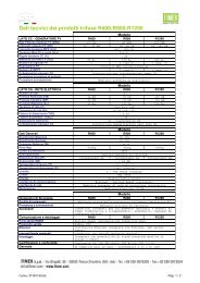
Grid connected nected PV Inverter series R25-R55<br />
R55<br />
<strong>Installation</strong> <strong>and</strong> <strong>Stat</strong> <strong>up</strong> <strong>user</strong> <strong>manual</strong> <strong>for</strong> 1-<strong>phase</strong> <strong>inverter</strong>
________________________________________________________________________________<br />
CE certificate<br />
_______________________________________________________________________________<br />
1
________________________________________________________________________________<br />
Environmental <strong>Stat</strong>ement<br />
The grid connected PV <strong>inverter</strong> of Fimer reduce raw material consumption <strong>and</strong> scrap throughout their long working<br />
lifetime. In typical applications, these positive environmental effects far outweigh the negative impacts of product<br />
manufacture <strong>and</strong> end-of-life disposal.<br />
Product packaging is of good quality <strong>and</strong> can be re-used. All the products come in strong cardboard cartons which<br />
themselves have a high recycled fibre content. If not re-used, these containers can be recycled. Polythene, used on the<br />
protective film <strong>and</strong> bags from wrapping product, can be recycled in the same way. Fimer’s packaging strategy favours<br />
easily recyclable materials of low environmental impact, <strong>and</strong> regular reviews identify opportunities <strong>for</strong> improvement.<br />
Copyright– All rights reserved<br />
This publication is property of Fimer S.p.A. Any divulgation or reproduction of it as a whole or in part in <strong>for</strong>bidden<br />
unless expressly authorised. The contents, pictures <strong>and</strong> texts can be use <strong>for</strong> training the installers <strong>and</strong> the end <strong>user</strong>s of<br />
the product. This <strong>manual</strong> cannot be used any other scope different from the <strong>user</strong> instruction necessary to install, control<br />
<strong>and</strong> run the solar <strong>inverter</strong>. While every care has been taken during the preparation, the compilation <strong>and</strong> checking to<br />
ensure the accuracy of the in<strong>for</strong>mation contained in this <strong>manual</strong>, Fimer S.p.A. cannot assume any responsibility <strong>for</strong><br />
events caused by improper use of the same. The same statement is made on behalf of all persons <strong>and</strong> companies<br />
involved in the creation <strong>and</strong> the production of this <strong>manual</strong>. Fimer S.p.A. reserves the right to make design or functional<br />
modifications, without prior notice <strong>and</strong> at any time; picture are just an example.<br />
_____________________________________________________<br />
INDEX<br />
1. INTRODUCTION......................................................................................................................................... 4<br />
2. GENERAL INFORMATION........................................................................................................................ 5<br />
2.1 Contents of delivery.................................................................................5<br />
2.2 Delivery inspection..................................................................................5<br />
3. SAFETY INSTRUCTION..................................................................................................................................... 5<br />
4. MOUNTING AND CONNECTION OF THE INVERTER............................................................................................ 7<br />
4.1 Selecting the installation place..........................................................7<br />
4.2 Criteria <strong>for</strong> placement of the equipment ...........................................7<br />
4.3 Criteria of mounting of the <strong>inverter</strong> ..................................................8<br />
4.4 Instruction <strong>for</strong> the electrical connections........................................10<br />
4.5 Connection to the AC grid...............................................................11<br />
4.5.1 Direct connection on the PCB board to the internal connectors only <strong>for</strong> IP21 model 12<br />
4.5.2 AC connection using the Wiel<strong>and</strong> connector...................................12<br />
4.6 PV generator connection.................................................................14<br />
4.7 Additional PE connection................................................................15<br />
5. OVERVOLTAGE AND LIGHTNING PROTECTION.............................................................................. 15<br />
5.1 When is lightening protection required?.........................................16<br />
5.2 Surge protection <strong>and</strong> cable laying...................................................16<br />
5.3 Lightning protection of the PV generator .......................................16<br />
5.4 Lightning protection of the grid side of the <strong>inverter</strong> .......................18<br />
5.5 Lightning protection of the communications <strong>and</strong> sensor connections18<br />
5.6 Warranty claims in the case of surge damage.................................18<br />
6. START-UP OF THE INVERTER......................................................................................................................... 18<br />
7. TROUBLE SHOOTING AND ERROR REPORT..................................................................................................... 20<br />
7.1 Monitoring of the AC mains connection..........................................20<br />
7.2 Monitoring of PV generator............................................................21<br />
8. TECHNICAL DATA......................................................................................................................................... 22<br />
_____________________________________________________________________________<br />
2
________________________________________________________________________________<br />
9. WARRANTY CONDITIONS.............................................................................................................................. 25<br />
10. SERVICE ....................................................................................................................................................... 26<br />
________________________________________________________________________________<br />
3
________________________________________________________________________________<br />
1. INTRODUCTION<br />
Dear Customer,<br />
congratulations on the purchase of our <strong>inverter</strong>; we are delighted that you have chosen it <strong>and</strong><br />
with this device you have acquired a solar <strong>inverter</strong> <strong>for</strong> the mains connection of photovoltaic<br />
systems. Our <strong>inverter</strong>s have been developed, produced <strong>and</strong> inspected with great care <strong>and</strong> by the<br />
means of the latest technology that allow to our device to be an high quality, very robust <strong>and</strong><br />
innovative device. We comply with the ISO 9001 regulations.<br />
The <strong>FIMER</strong> converters are trans<strong>for</strong>merless <strong>inverter</strong>s <strong>for</strong> the s<strong>up</strong>ply of electricity from solar cells to<br />
the public grid. The high efficiency of the our <strong>inverter</strong>s achieved by the use of modern<br />
semiconductors, the use of high-quality parts <strong>and</strong> the optimisation of all components. Its numerous<br />
integrated communications options mean that our <strong>inverter</strong> is easy to maintain <strong>and</strong> operate. Along<br />
side the usual RS232 <strong>and</strong> RS485 interfaces, there is also an Ethernet interface. The d integrated 4<br />
line display offers a wide range of possibilities <strong>for</strong> communication <strong>and</strong> data transfer.<br />
The following documentation provides installation instructions <strong>for</strong> the <strong>inverter</strong>. Please observe at all<br />
times the safety regulations which are described in these documents. <strong>Installation</strong> of the <strong>inverter</strong><br />
must always be carried out by an electrical installer who is familiar with this documentation <strong>and</strong> is<br />
aware of the safety regulations.<br />
The contents of the <strong>manual</strong> will help you to solve the major part of doubts <strong>and</strong> problems that could<br />
be rise or happen during the operation of the device, anyway if you have some more questions,<br />
please get in touch with your installer or call us. In order to obtain the last version of the <strong>user</strong><br />
<strong>manual</strong> you can download it from our web-side.<br />
We ask you to keep with care <strong>and</strong> keep this <strong>manual</strong> h<strong>and</strong>y <strong>for</strong> quick reference in case of future<br />
consultations.<br />
Thanks <strong>for</strong> having chosen a <strong>FIMER</strong> product<br />
_____________________________________________________________________________<br />
4
________________________________________________________________________________<br />
2. GENERAL INFORMATION<br />
2.1 Contents of delivery<br />
Nr. 1 PV <strong>inverter</strong><br />
Nr. 1 Mounting frame<br />
Nr. 1 CD-Rom containing the Operating instructions, installation instructions, dimensioning tool<br />
SUNBuilder, <strong>FIMER</strong>Net communications program<br />
Nr. 1 <strong>Installation</strong> <strong>user</strong> <strong>manual</strong><br />
Nr. 2 screws <strong>for</strong> fixing the <strong>inverter</strong> to the mounting frame<br />
Nr.1 Wiel<strong>and</strong> connector in necessary to connect the <strong>inverter</strong> to the AC grid<br />
Nota: <strong>for</strong> the <strong>inverter</strong>s whose protection degree system is IP 54 there are 4 screws, type M3, which<br />
must be used <strong>and</strong> firmly fastened after installation of the cable <strong>and</strong> the connectors.<br />
2.2 Delivery inspection<br />
Please check the s<strong>up</strong>plied <strong>inverter</strong> thoroughly. If the packaging is damaged in such a way that the<br />
<strong>inverter</strong> has been affected, or the <strong>inverter</strong> itself damaged, please contact us, the local distributor or<br />
the installer immediately. We will reco<strong>up</strong> the damages from the delivery firm on your behalf.<br />
The technical in<strong>for</strong>mation (part number, technical data <strong>and</strong> serial number) of the <strong>inverter</strong> are<br />
contained in the product label pasted to the right side of the hit sink, if these values doesn’t<br />
correspond to the ones of the <strong>inverter</strong> then don’t mount the converter <strong>and</strong> contact immediately the<br />
distributor or the manufacturer. Every in<strong>for</strong>mation related to the <strong>inverter</strong> <strong>and</strong> necessary to identify<br />
the <strong>inverter</strong> is contained on the product label, the S/N identify the device <strong>and</strong> it is contained in the<br />
product label.<br />
3. Safety instruction<br />
INFORMATION: The following must be read be<strong>for</strong>e first operating the unit in order to<br />
avoid personal injury <strong>and</strong>/or damage to the equipment. These regulations must be<br />
observed at all times.<br />
Do not attempt to install or operate this unit be<strong>for</strong>e carefully reading all the documents<br />
s<strong>up</strong>plied. These safety instructions <strong>and</strong> all operating instructions are to be read through<br />
be<strong>for</strong>e any carrying out any work with the equipment. If the equipment is sold, rented<br />
out or otherwise provided to a third party, this safety in<strong>for</strong>mation must be s<strong>up</strong>plied as well.<br />
Appropriate use: this equipment is only intended <strong>for</strong> the use described in these operating<br />
instructions, i.e. as an <strong>inverter</strong> <strong>for</strong> photovoltaic equipment connected to electricity grids.<br />
All safety rules must be observed. <strong>Installation</strong> must only be carried out in the way<br />
described in these instructions. No modifications of any kind to the equipment or its external wiring<br />
are allowed <strong>and</strong> lead to serious safety problems <strong>and</strong> risks to life <strong>and</strong> limb.<br />
Surface of equipment may become hot. Danger of injury <strong>and</strong> fire!<br />
Even if the device has been developed according to the main national <strong>and</strong> international<br />
safety st<strong>and</strong>ards, some components inside the device can get during the st<strong>and</strong>ard working<br />
________________________________________________________________________________<br />
5
________________________________________________________________________________<br />
mode to high value of temperature, there<strong>for</strong>e we recommend to avoid to touch the hit sink <strong>and</strong> the<br />
device where the power components are mounted.<br />
Warning Inappropriate treatment of this equipment <strong>and</strong> failure to observe the warnings<br />
here given, or inappropriate interference with the safety features, can lead to damage to<br />
the equipment, bodily injury electric shock or in extreme cases to death. Wrong connection can lead<br />
to high voltage! Danger to life <strong>and</strong> limb from electric shock.<br />
The safety requirement are below described <strong>and</strong> they agree to the st<strong>and</strong>ard ANSI guideline:<br />
Danger <strong>and</strong> safety class according to ANSI<br />
Symbols <strong>and</strong> definitions<br />
Danger<br />
Warning<br />
Danger class describe he risk when safety regulations are<br />
not observed<br />
The result will be serious injury or death.<br />
Death or serious injury may result.<br />
Caution<br />
Bodily injury or damages to property may<br />
result.<br />
The manufacturer doesn’t accept any responsibility <strong>for</strong> damage caused by failure to observe<br />
warnings given in these operating instructions.<br />
Be<strong>for</strong>e starting to operate the equipment, the operating instructions, warnings <strong>and</strong> safety regulations<br />
must be thoroughly read through. If the documentation cannot be fully understood in the present<br />
language, please in<strong>for</strong>m the s<strong>up</strong>plier <strong>and</strong> request further in<strong>for</strong>mation.<br />
Safe <strong>and</strong> problem-free operation of this equipment requires appropriate <strong>and</strong> professional transport,<br />
storage, mounting <strong>and</strong> installation, as well as careful servicing <strong>and</strong> maintenance of this equipment.<br />
Only trained <strong>and</strong> qualified personnel should work with electrical equipment.<br />
Only appropriately qualified <strong>and</strong> trained personnel should work on or in the vicinity of this<br />
equipment. Qualified in this contexts means that the worker is adequately familiar with the<br />
mounting, installation <strong>and</strong> operation of the product <strong>and</strong> with all the corresponding warnings <strong>and</strong><br />
safety requirements.<br />
The environmental conditions described in the product documentation must be met.<br />
Please observe the danger warnings given below in the documentation.<br />
_____________________________________________________________________________<br />
6
________________________________________________________________________________<br />
4. Mounting <strong>and</strong> connection of the <strong>inverter</strong><br />
4.1 Selecting the installation place<br />
When planning a photovoltaic installation, an appropriate place must be found <strong>for</strong> the <strong>inverter</strong>. In<br />
order to help find the optimal location, the following covers the most important criteria which must<br />
be considered.<br />
If the ambient conditions <strong>and</strong> the related suggestions described in this <strong>manual</strong> are not respected then<br />
it could happened some unexpected damages to the device <strong>and</strong> it is considered by the manufacturer<br />
like an improper use of the <strong>inverter</strong>.<br />
The life-span of an <strong>inverter</strong> is strongly influenced by the prevailing environmental conditions. The<br />
higher the temperature, the shorter the life-span of the <strong>inverter</strong> will be.<br />
We strongly suggest you not to install the <strong>inverter</strong> directed exposed to the UV ray of to the direct<br />
exposition to the sun. This is not allowed because extended exposure to UV rays can damage the<br />
display <strong>and</strong> the keypad. In addition, warming due to sunlight can cause unnecessary heat stress to<br />
the equipment.<br />
A permanently humid environment will also negatively affect the life-span of the equipment. The<br />
ideal mounting location is dry <strong>and</strong> climate controlled. This also applies to an <strong>inverter</strong> with the IP 54<br />
protective system.<br />
Don’t install the <strong>inverter</strong> on a mobile wall or on a structure that is subjected to vibration. A strong,<br />
robust <strong>and</strong> un-flammable wall is the ideal place where install the device; pay attention because the<br />
heat-sink could get to high temperature level, 80° C degree could be the value of the temperature in<br />
object.<br />
Install possibly the <strong>inverter</strong> in a clean <strong>and</strong> dry place in order tot avoid that any liquid or external<br />
object get into the devoice from the air input; clean periodically the device with a dry cloth also<br />
when the converter is off.<br />
Do not use the converter as a shelf to s<strong>up</strong>port heavy loads or objects or used as a carrier <strong>and</strong> s<strong>up</strong>port<br />
<strong>for</strong> other types of structure.<br />
During the operation, the device can produce some noise that make it preferable not to install the<br />
device in a residential installation.<br />
If you install the <strong>inverter</strong> inside a cabinet or similar place, you must ensure adequate ventilation to<br />
remove heat <strong>and</strong> must ensure the free circulation of air around the external housing <strong>and</strong> the heat<br />
sink of the converter.<br />
NEVER install in potentially explosive environments <strong>and</strong> in the presence of saline condition that<br />
may inevitably reduce per<strong>for</strong>mance <strong>and</strong> efficiency. The <strong>inverter</strong> must not come into contact with<br />
acids, ammonia or corrosive gases such as those present in the stables or chemical plants.<br />
4.2 Criteria <strong>for</strong> placement of the equipment<br />
The equipment is intended <strong>for</strong> wall mounting. It should be noted that less current flows on the<br />
generator side than on the grid side.<br />
________________________________________________________________________________<br />
7
________________________________________________________________________________<br />
Consideration should be paid to the accessibility of the equipment <strong>for</strong> the purposes of mounting or<br />
later servicing. <strong>Installation</strong> at eye level makes the display more easily read.<br />
The distance above <strong>and</strong> below to the nearest <strong>inverter</strong>, c<strong>up</strong>board, ceiling or other object must be at<br />
least 30 cm, <strong>and</strong> it is best if it is at least 50 cm. Please allow adequate fresh air access <strong>and</strong> warm air<br />
removal to prevent unnecessary overheating.<br />
The distance on the left <strong>and</strong> right of the equipment to the nearest <strong>inverter</strong>, meter, c<strong>up</strong>board, wall or<br />
other object must be at least 10 cm, <strong>and</strong> it is better if it is 15 cm.<br />
The environmental temperature must be between –20 °C <strong>and</strong> +40 °C.<br />
Please take note of the grid impedance at the s<strong>up</strong>ply point.<br />
Caution<br />
Due to the high system voltage, a lower current always flows on the DC<br />
side as on the AC side. Losses <strong>for</strong> a given cable size are there<strong>for</strong>e greater<br />
<strong>for</strong> the AC wiring as <strong>for</strong> the DC wiring. For this reason, given thermal<br />
considerations it is advisable to place the <strong>inverter</strong> near to the meter box, at<br />
best in the basement..<br />
4.3 Criteria of mounting of the <strong>inverter</strong><br />
The <strong>inverter</strong> has to mounted to a secure <strong>and</strong> fixed surface on the wall with the help of the mounting<br />
frame included into the delivery.<br />
Mounting frame<br />
For this you require screws <strong>and</strong> dowels appropriate to the qualities of the wall (4 of each).<br />
Mark the holes which need to be bored in the wall, using the mounting frame as a guide. Please be<br />
careful to ensure that these are vertically placed.<br />
Insert the dowel <strong>and</strong> screw the mounting frame to the wall with the screws. When selecting the<br />
screws, note that the weight is approx. 22 kg.<br />
Hang the <strong>inverter</strong> from above from the mounting frame. The mounting frame will then be between<br />
the outermost slats of the heat sink. The two screws s<strong>up</strong>plied, M5x20, are now to be screwed into<br />
the corresponding holes of the mounting frame through the heat sink in order to fix the <strong>inverter</strong> to<br />
the wall in its right place. For this you will require an allen key. It may be necessary to lift the unit<br />
by 1 - 2 mm in order to be able to screw the screws without resistance.<br />
Check that the equipment is secure <strong>and</strong> well fixed to the wall!<br />
_____________________________________________________________________________<br />
8
________________________________________________________________________________<br />
Mechanical dimensions f the <strong>inverter</strong>:<br />
IP21 Model:<br />
Type IP21 R25 R35 R50 R55<br />
WxDxH (mm)<br />
305x130x450<br />
IP54 Model:<br />
Type IP54 R25 R35 R50 R55<br />
WxDxH (mm)<br />
3105x130x510<br />
Removal of the s<strong>up</strong>erior cover<br />
It is not normally necessary to open the cover. This is necessary only with the IP 21 casing when<br />
you have chosen the screw connection means of mounting the AC or DC cable.<br />
Please avoid in all cases opening the IP 54 chase, as this can lead to damage to the seals <strong>and</strong><br />
there<strong>for</strong>e no more protection being provided. Opening the IP 54 casing leads to loss of warranty<br />
cover! If it’s necessary to install an internal modem or an internal RS485 card please define this<br />
accessories during the order of the <strong>inverter</strong> in order to avoid to open the case of the converter.<br />
Opening of the <strong>inverter</strong> must only be carried out when the power is switched off! First read the<br />
following chapters if voltage is still present in the <strong>inverter</strong>.<br />
If the <strong>inverter</strong> is free from voltage from both grid <strong>and</strong> the solar generator, a 5 minute waiting period<br />
is necessary to allow the internal condensers to discharge be<strong>for</strong>e the cover can be opened.<br />
First, unscrew all screws, taking care that the cover does not fall after unscrewing the last screw.<br />
Then carefully move the cover a few centimetres, carefully pull the flat cable out of the electronic<br />
assembly <strong>and</strong> then place the cover to one side. Please take care not to damage the flat cable, which<br />
is connected to the operating unit (LCD, keypad <strong>and</strong> LED) in the cover over the electronic assembly<br />
in the unit.<br />
When replacing the cover, the flat cable must first carefully reconnected to the electronic assembly,<br />
<strong>and</strong> the cover then replaced <strong>and</strong> secured with the 8 screws.<br />
When connecting <strong>and</strong> disconnecting the ribbon, please ensure that you do not tilt the plug, bend any<br />
pins or pull unnecessarily on any wires. Do not touch the electronic assembly directly under any<br />
circumstances.<br />
________________________________________________________________________________<br />
9
________________________________________________________________________________<br />
Please observe the ESD regulations. Put a potential equalisation between yourself <strong>and</strong> the flat place<br />
on the casing. Avoid in any circumstances touching any parts on the inside of the <strong>inverter</strong> with any<br />
other parts, plastic parts, foils, clothing etc.<br />
Replace the cover immediately after installation in order to protect the electronics.<br />
4.4 Instruction <strong>for</strong> the electrical connections<br />
The <strong>inverter</strong> must be installed by using the mounting frame that is present in the packaging of the<br />
<strong>inverter</strong> ant it is to be well fixed on the wall.<br />
Caution<br />
The electrical connection of the <strong>inverter</strong> <strong>and</strong> the turning on of the DC <strong>and</strong> AC current must take<br />
place in the order here below described<br />
When the <strong>inverter</strong> is securely mounted, the electrical connection of the equipment can take place.<br />
<strong>Installation</strong> of the converter must only be carried out by trained professionals. The installer must be<br />
approved by the responsible electricity company. All applicable safety regulations, the technical<br />
connection regulations of the company <strong>and</strong> all the national regulations must be observed: the<br />
CEI11-20 norm, the CEI 82-25 norm <strong>and</strong> the ENEL recommendation (“GUIDA PER LE CONNESSIONI<br />
ALLA RETE ELETTRICA ENEL DI DISTRIBUZIONE”) <strong>for</strong> the Italian market, VDE (German Association<br />
<strong>for</strong> Electrical, Electronic & In<strong>for</strong>mation Technologies) <strong>for</strong> German <strong>and</strong> north European market <strong>and</strong><br />
the RD1663/2000 rule <strong>for</strong> the Spanish market.<br />
The connection to the electrical grid can be made by using the AC connector (Wiel<strong>and</strong> RST20i3S)<br />
s<strong>up</strong>plied into the packaging of the <strong>inverter</strong>. The connection of the PV generator <strong>and</strong> the connection<br />
to the grid are made by means of locking rings in the connection area of the <strong>inverter</strong> or by means of<br />
various solar plug connector models (Tyco or Multi-Contact).<br />
Nota: The connection to the grid , on the AC side, or to the PV generator on the DC side directly to<br />
the PCB clamps, that are present inside the <strong>inverter</strong>, requires opening the casing cover, it is<br />
dangerous <strong>and</strong> it require opening the cover <strong>for</strong> either the grid or the DC connections; in this case the<br />
seal of the IP54 model can be damaged.<br />
Additional earth-leakage circuit breaker<br />
Please note that the <strong>FIMER</strong> <strong>inverter</strong> has an integrated AD/DC sensitive protective switch. For this<br />
reason no external earth-leakage circuit breaker is normally required.<br />
Should an earth-leakage circuit breaker already be available, or should you need one <strong>for</strong> one of the<br />
following reasons, please note that the residual current may be greater than 30 mA <strong>and</strong> there<strong>for</strong>e<br />
that use of an external earth-leakage circuit breaker with a can lead to incorrect releases. The<br />
protective switch must there<strong>for</strong>e have a sensitivity of 300 mA<br />
In some regions, the electricity s<strong>up</strong>plier does not use a normal TNC network but rather a TT<br />
network. This means that the electricity s<strong>up</strong>plier cannot offer the protection of a neutral wire (PEN)<br />
<strong>and</strong> thus that the customer’s system must include its own built-in earthing in order to provide this<br />
protection. The earth resistances can be, depending on how the system is set <strong>up</strong>, very high.<br />
For this reason we recommend that in this case an additional earth-leakage circuit breaker be<br />
installed directly in the fuse box.<br />
Your electricity company will be able to give you further in<strong>for</strong>mation about this issue.<br />
_____________________________________________________________________________<br />
10
________________________________________________________________________________<br />
Additional voltage protection<br />
The <strong>inverter</strong> is equipped with an integrated interface protection device <strong>and</strong> voltage protection that<br />
verifies the grid voltage variation so that it acts when the voltage value is at 115% (=265 V) of the<br />
nominal grid voltage, which means that the <strong>inverter</strong> will switch off if the mains voltage exceeds this<br />
value.<br />
The voltage protection works by monitoring the moving average over 4 minutes. However some<br />
electricity companies or some other European countries prescribe a lower threshold or in any are<br />
different, e.g. 106% (=243 V). In this case, the threshold must be set to a lower value (Parameter<br />
51, VACMAX). You will find this parameter in the Input/Output menu of the <strong>inverter</strong>. Parameter<br />
51 is protected with the level 3 password. Changes to the voltage protection may only be made after<br />
consulting the responsible electricity company.<br />
The same consideration is valid also <strong>for</strong> the Parameter number 53 (VACMIN) that is related to the<br />
minimum grid voltage value <strong>and</strong> it is verified constantly by the <strong>inverter</strong> according to the different<br />
national st<strong>and</strong>ards as prior described.<br />
In the end the same integrated interface protection device controls the minimum <strong>and</strong> maximum<br />
values of the frequency of the grid in order to act to disconnect the device if the electrical variable<br />
get out of the allowed range of value according to the different national regulations.<br />
4.5 Connection to the AC grid<br />
The connecting cable to the electricity AC grid have to be correctly designed <strong>and</strong> dimensioned; <strong>for</strong><br />
example, recommended wire cross-section <strong>for</strong> cable lengths <strong>up</strong> to 20m: 4/6 mm². We recommend<br />
using a cross-section of 4 mm² even <strong>for</strong> very short lengths of cable running to the meter box. The<br />
recommended cable section is as described in the below attached table.<br />
We recommend to install the protection fuse or similar protection device (magneto-thermal circuit<br />
breaker) as describe in the table<br />
Inverter model Fuse required Min section of the cable Suggested section of the cable<br />
R25 16 A 2,5 mm 2 4 mm 2<br />
R35 20 A 2,5 mm 2 4 mm 2<br />
R50 25 A 4 mm 2 4 mm 2<br />
R55 30 A 6 mm 2 6 mm 2<br />
If installing more than one <strong>inverter</strong>, please leave a distance of at least one unit (approx. 18mm)<br />
between their respective fuses. This will prevent fuses being fused by warming each other.<br />
Caution<br />
Take care to use an adequately large cross-section of cable so as not to create too large an<br />
increase in the grid impedance (internal resistance of the electricity s<strong>up</strong>ply grid) from the wiring<br />
between the grid <strong>and</strong> the <strong>inverter</strong>. The impedance value is the sum of the grid impedance at the<br />
building’s connection <strong>and</strong> all resistance values of the other cables <strong>and</strong> terminals. With a high grid<br />
impedance, i.e. with long lengths of cabling on the AC side, the voltage at the grid terminals of<br />
the <strong>inverter</strong>s is increased when feeding power to the network. This voltage is measured by the<br />
<strong>inverter</strong>. Should it exceed a defined limit (preset to 265 V), the <strong>inverter</strong> switches off due to grid<br />
overvoltage. This must be considered when dimensioning the AC circuit. Please note also that<br />
warming of the cable will result in reduced per<strong>for</strong>mance of your system.<br />
________________________________________________________________________________<br />
11
________________________________________________________________________________<br />
The grid connection has 3 cables (N, L, PE). The underside of the casing has a cable connector to<br />
allow the wiring to be done properly.<br />
Be<strong>for</strong>e connecting the network cable to the unit, please check that it is free from voltage.<br />
We suggest you to install an automatic magneto-thermal brake circuit (25 A value recommended)<br />
between the <strong>inverter</strong> <strong>and</strong> the grid in order to allow the disconnection of the device <strong>for</strong> maintenance<br />
<strong>and</strong> security protection.<br />
4.5.1 Direct connection on the PCB board to the internal connectors only <strong>for</strong> IP21 model<br />
Only if you want to connect the <strong>inverter</strong> to the grid connection the AC cable to the connectors<br />
present on the PCB board you have to acts as following described.<br />
Feed the stripped <strong>and</strong> bared 3-wire cable through the cable connector. Using a slotted screwdriver,<br />
attach the N, L <strong>and</strong> PE wires to the correct PCB terminals, corresponding to the markings (from left<br />
to right: N, L, PE). The PCB terminal has a spring clip. Feed the slotted screwdriver from<br />
underneath into the square hole until it makes contact <strong>and</strong> press the screwdriver <strong>up</strong>wards. At the<br />
same time, put the wire from underneath into the round hole <strong>and</strong> then release the screwdriver.<br />
As shown in the picture connect in this way the AC cable:<br />
N=blue<br />
L=grey<br />
PE=yellow-green<br />
<br />
<br />
<br />
N: Neural cable correspond to the Blue terminal<br />
L: Line cable correspond to the Grey terminal<br />
PE: Yellow/Green terminal correspond to the ground<br />
The first cable that must be connected is the PE cable <strong>and</strong> it is the last one that<br />
must be disconnected when you uninstall the <strong>inverter</strong>.<br />
The grid connection of the plant must be unique.<br />
ACCORDING TO THE LOW VOLTAGE REGULATION AND NORM BE SURE AND VERIFIES THAT THE PE<br />
CABLE IS ALWAYS CONNECTED ON THE PLANT AND TO THE INVERTER.<br />
Note: For reasons of electromagnetic compatibility, it is absolutely essential that the cable comes<br />
straight out of the <strong>inverter</strong>. You must avoid any kinks or loops being left in the unit.<br />
Screw the cord grip or wiring seal of the cable connection tightly <strong>up</strong>.<br />
4.5.2 AC connection using the Wiel<strong>and</strong> connector<br />
On the bottom right side of the unit you will find a plug connector <strong>for</strong> the AC connection, type<br />
RST20I3S, manufacturer Wiel<strong>and</strong>-electric.<br />
This connector meets the requirements of a high degree of protection <strong>and</strong> rigidity <strong>and</strong> can conduct<br />
electricity <strong>up</strong> to 25A.<br />
In an emergency it can be pulled out whilst the unit is in operation.<br />
_____________________________________________________________________________<br />
12
________________________________________________________________________________<br />
The plug which the cable will be connected included in the unit.<br />
The Wiel<strong>and</strong> connector are suitable <strong>for</strong> flexible cable whose section is<br />
<strong>up</strong> to 4mm 2 <strong>and</strong> <strong>for</strong> rigid cable whose section is <strong>up</strong> to 6mm 2 .<br />
For emergency situation you can switch off the <strong>inverter</strong> only by<br />
disconnect the AC connector.<br />
Open the unit by pressed with a screwdriver on the security latches on the side. Inside the connector<br />
there are the connection terminals necessary <strong>for</strong> the grid connection. The terminals are clearly<br />
identified <strong>and</strong> named with the following short terms L-N- .<br />
Bend the cable into shape first in order to avoid tension in the plug. Strip<br />
approx. 30 mm of the cable. Cut the wires to the same length. Use a stripper<br />
to remove approx. 10 mm of insulation.<br />
If using a cord, crimp the appropriate cable end sleeves onto the three bare<br />
wires of the cable. Now open the connecting nut of the connector <strong>and</strong> feed<br />
the connecting cable through the connecting nut. The grid connection has 3<br />
wires (N, L, PE).<br />
Once you have pulled the grid connection cable<br />
through the connecting nut, connect the grid cable to<br />
the connection terminals as follows:<br />
L=grey N=blue PE=yellow-green<br />
Pay attention not to connect the L cable in the N terminal <strong>and</strong> reverse.<br />
Connect always at first the PE cable .<br />
Check the cable is correctly connected. Push the two parts of the plug<br />
together until the security clips snap shut on both sides.<br />
Then do <strong>up</strong> the connecting nut tightly.<br />
Note: The IP 54 casing type has external DC <strong>and</strong> AC connections at the<br />
bottom of the additional cover. This casing type is delivered at the AC-<br />
Side only with the Wiel<strong>and</strong> plug.<br />
internal connections are freely accessible.<br />
This additional cover protects the connections from<br />
dirt <strong>and</strong> water spray. Inside of this additional cover<br />
there are integrated connections, different interfaces<br />
<strong>and</strong> digital relay outputs <strong>and</strong> inputs.<br />
To connect your R-series <strong>inverter</strong> to a IP 54 casing,<br />
first lift <strong>up</strong> the additional cover. Unscrew the 4<br />
screws on the side of the cover. Then remove the<br />
cover at the bottom part of the casing. Now the<br />
________________________________________________________________________________<br />
13
________________________________________________________________________________<br />
4.6 PV generator connection<br />
The PV input cable from the solar modules must<br />
be dimensioned in order to avoid the power<br />
losses when the power is transferred on the same<br />
cables that are between the <strong>inverter</strong> <strong>and</strong> the<br />
modules. We suggest you to install the <strong>inverter</strong><br />
not too far from the PV generator.<br />
Every PV string must be dimensioned in order to<br />
s<strong>up</strong>ply a DC voltage whose maximum value is<br />
750 VDVC.<br />
In the bottom part of the device are placed two (2) DC terminals ,“+” <strong>and</strong> “-“ terminals, <strong>for</strong> each<br />
string that allow to connect a string of PV modules, <strong>and</strong> the max number of string in parallel<br />
between themselves that can be connected are three.<br />
Only <strong>for</strong> the IP21 models you can connect directly the PV strings to the internal DC terminals of the<br />
DC switch using the suitable connecting nut that allow you to put the cable into the interior of the<br />
<strong>inverter</strong>.<br />
In the st<strong>and</strong>ard delivery the <strong>inverter</strong> is equipped with external connectors <strong>for</strong> both model IP21 <strong>and</strong><br />
IP54.<br />
Connectors from MULTI-CONTACT manufacturer type MC4:in the following table you can find<br />
the references <strong>for</strong> the DC cables that have to be used:<br />
Polarity MC type of connector Section of the DC cable Note<br />
PV- PV-KST4/2.5I-UR 1.5 ~ 2.5 mm 2 / 14 AWG Ø ext.-cable 3-6<br />
PV- PV-KST4/2.5II-UR 1.5 ~ 2.5 mm 2 / 14 AWG Ø ext.-cable 5.5-9<br />
PV- PV-KST4/6I-UR 4 ~ 6 mm 2 / 12 o 10 AWG Ø ext.-cable 3-6<br />
PV- PV-KST4/6II-UR 4 ~ 6 mm 2 / 12 o 10 AWG Ø ext.-cable 5.5-9<br />
PV+ PV-KBT4/2.5I-UR 1.5 ~ 2.5 mm 2 / 14 AWG Ø ext.-cable 3-6<br />
PV+ PV-KBT4/2.5II-UR 1.5 ~ 2.5 mm 2 / 14 AWG Ø ext.-cable 5.5-9<br />
PV+ PV-KBT4/6I-UR 4 ~ 6 mm 2 / 12 o 10 AWG Ø ext.-cable 3-6<br />
PV+ PV-KBT4/6II-UR 4 ~ 6 mm 2 / 12 o 10 AWG Ø ext.-cable 5.5-9<br />
Connectors from Tyco manufacturer type Solarlok: in the following table you can find the<br />
references <strong>for</strong> the DC cables that have to be used:<br />
Polarity Tyco- Solarlok series Section of the DC cable Positive female<br />
polarized connector<br />
Negative female<br />
polarized connector<br />
PV+ 1394462-1 2.5 mm 2 / 14 AWG ●<br />
PV- 1394462-2 2.5 mm 2 / 14 AWG ●<br />
PV+ 1394462-3 4 mm 2 / 12 AWG ●<br />
PV- 1394462-4 4 mm 2 / 12 AWG ●<br />
PV+ 1394462-5 6 mm 2 / 10 AWG ●<br />
PV- 1394462-6 6 mm 2 / 10 AWG ●<br />
Note: The polarity of the voltage at the plug must be checked be<strong>for</strong>e connection to the PV system.<br />
The PV generator cabling is connected on the left in the connection box. The correct polarity at<br />
connection is essential. A short reverse polarity (less than 1 second) or with very low irradiation (<<br />
100 W/m2) is tolerable, but otherwise damage to the equipment will result.<br />
_____________________________________________________________________________<br />
14
________________________________________________________________________________<br />
S<strong>up</strong>ply the <strong>inverter</strong> from the DC side according to the technical specs that are shown <strong>and</strong><br />
defined in the product label.<br />
Attention<br />
Warning<br />
Caution<br />
PRECAUTION<br />
To protect to the maximum extent possible against the risk of dangerous touch voltages during<br />
the mounting of the PV system, the plus <strong>and</strong> the minus wires must be kept apart from the PE.<br />
Check that the PV generator installation is earth free be<strong>for</strong>e connecting the PV generator to the<br />
<strong>inverter</strong>.<br />
WARNING<br />
In the case of trans<strong>for</strong>merless <strong>inverter</strong>s, only modules of protection class II may be connected.<br />
Check whether your modules belong to this protection category. The module frames must also be<br />
earthed.<br />
DANGER<br />
After having disconnected the DC string from the <strong>inverter</strong>, pay attention because you have to<br />
wait 5 min. be<strong>for</strong>e open the device; in fact high value of voltage are still present inside the<br />
<strong>inverter</strong> during the period in object <strong>and</strong> you have to wait <strong>for</strong> the discharge of the capacitors that<br />
are present inside the converter.<br />
4.7 Additional PE connection<br />
In the bottom part of the Fimer <strong>inverter</strong> is present an additional PE terminal that must be wired in<br />
order to ground the device if leakage current s<strong>up</strong>erior than 30mA are present.<br />
Warning<br />
AVVISO<br />
For equipment with a leakage current of more than 30 mA, VDE regulations require an additional<br />
PE connection. For this purpose please use the PE screw on the bottom of the casing. Use a<br />
yellow-green cable with a cross-section of 10 mm 2 . Connect the other end of the PE cable to the<br />
potential equalisation panel.<br />
5. OVERVOLTAGE AND LIGHTNING PROTECTION<br />
It’s very important avoid that overvoltage <strong>and</strong> lightning that occurs during summer storm or other<br />
bad weather conditions could damage the <strong>inverter</strong> <strong>and</strong> the PV installation. It is recommended to<br />
install some external devices able to protect the PV plan against this overvoltage, like <strong>for</strong> example<br />
the varistors or the surge protection device (SPD) that should be installed both on the PV side <strong>and</strong><br />
on the grid side.<br />
The main aim of the lightning <strong>and</strong> surge protection is to protect your solar installation, your<br />
building <strong>and</strong> your other electrical equipment in the case of a lightening strike. In addition an<br />
effective lightening protection system ensures the trouble free operation of the PV equipment.<br />
In order to ensure this, the solar generator, the grid connection <strong>and</strong> all communications <strong>and</strong> sensor<br />
connections of the <strong>inverter</strong> must be appropriately protected.<br />
To ensure this we recommend the following suggestion:<br />
A careful risk assessment of your premises, taking into consideration the way in which the<br />
<strong>inverter</strong> is mounted.<br />
<strong>Installation</strong> of lightening protection on the DC side of the <strong>inverter</strong>, preferably housed in the<br />
generator switch box.<br />
<strong>Installation</strong> of lightening protection on the AC side of the <strong>inverter</strong>, preferably housed in the<br />
house’s meter box.<br />
________________________________________________________________________________<br />
15
________________________________________________________________________________<br />
<br />
Protection of the other connections of the <strong>inverter</strong>: sensors, RS485 connections, Ethernet,<br />
telephone connection etc.<br />
5.1 When is lightening protection required?<br />
If the PV equipment is installed in a public building,( e.g. on a meeting place hospital), then<br />
lightening protection is required by law.<br />
This applies also to particular buildings such as hospitals, tower blocks, schools, nurseries <strong>and</strong><br />
buildings at risk of fire or explosion.<br />
In addition, requirements of the insurers must be observed. These require lightening protection on<br />
the basis of European norm that in Italian correspond to the CEI81-10 guideline <strong>and</strong> in north Europe<br />
correspond to VDS2010.<br />
Should these regulations not be observed, the insurance cover is at risk.<br />
Should there be no absolute requirement <strong>for</strong> lightening protection to be installed, it is a decision of<br />
the building’s owners whether or not to protect their building <strong>and</strong> the PV equipment by installing<br />
such protection.<br />
5.2 Surge protection <strong>and</strong> cable laying<br />
The <strong>inverter</strong> is an important component of a PV installation. Although such installations are<br />
exposed to harsh environmental conditions, a lightening current of a few kA can ruin the sensitive<br />
electronics.<br />
Faulty <strong>inverter</strong>s lead to complete failure of the PV installation.<br />
Surges can come from either the generator connection or the 230 V side. In order to protect the PV<br />
generator, surge arresters are connected to the generator connection box, <strong>and</strong> these protective<br />
measures are repeated on the DC side of the <strong>inverter</strong> (DC switch location).<br />
Surges from the power s<strong>up</strong>ply network can be controlled with surge protection devices on the 230 V<br />
side of the <strong>inverter</strong> or in the low voltage section.<br />
A large distance between the cables leads to kinking of the cables. The greater the kinking, the<br />
greater the danger of induced voltage (<strong>up</strong> to several thous<strong>and</strong> volts) which can ruin the connected<br />
equipment. There<strong>for</strong>e the DC+ <strong>and</strong> DC– cables should be as parallel as possible <strong>and</strong> lie close<br />
together. Twisting the two together is ideal (2 twists/meter).<br />
5.3 Lightning protection of the PV generator<br />
Important: direct injection of lightning currents into the solar generator <strong>and</strong> thus on into the <strong>inverter</strong><br />
must be avoided! The separating distance must be observed.<br />
There are 3 separate cases to consider:<br />
Roof-top mounting with external lightning protection<br />
Your solar generator is mounted on the roof of your building. The building has external lightning<br />
protection, which is at a safe distance from the generator (typically 0.5 m). The system is within the<br />
range of the lightning conductor.<br />
_____________________________________________________________________________<br />
16
________________________________________________________________________________<br />
Here is recommend that you check both the available lightning protection <strong>and</strong> the separating<br />
distance between the external lightning protection <strong>and</strong> the solar generator. Further in<strong>for</strong>mation can<br />
be provided by e.g. a s<strong>up</strong>plier of lighting protection systems <strong>for</strong> PV systems. In the generator<br />
connection box, which is to be placed as close as possible to the generator, you require a surge<br />
diverted of class II. The frame <strong>and</strong> s<strong>up</strong>port of the solar generator, as well as the PE connection of<br />
the surge diverter, are to be connected to a PE wire with a cross-section of at least 16mm. This PE<br />
wire is to be connected to the potential equalisation plate in or by the building’s connection box.<br />
Take care that this lightning protection surge diverter is an adequate distance away from the<br />
<strong>inverter</strong>. The cable length here must be at least 5 metres. Alternatively, you can use a disconnecting<br />
impeder, which must then be built in to the plus <strong>and</strong> minus wires. If the distance between diverter<br />
<strong>and</strong> <strong>inverter</strong> is too small, the diverter will not function <strong>and</strong> the surge protection (varistor) built into<br />
the <strong>inverter</strong> is not capable of replacing an external surge/lightning conductor. We recommend that<br />
the lighting conductor is deployed at a permissible constant voltage of 800 or 1000 V.<br />
A complete flow chart <strong>and</strong> electric scheme <strong>for</strong> the protection of a PV plant against overvoltage <strong>and</strong><br />
lightning is here below attached:<br />
Roof-top mounting without external lightning protection<br />
Your solar generator is mounted on the roof of your building. The building has no external<br />
lightning protection. The system is not within the protection range of the lighting conductor.<br />
In this, the same is applicable as in the above section, except that you must earth your solar<br />
generator in a way in such as way as is suitable <strong>for</strong> dealing with lightning. In addition, the<br />
external surge/lightning diverter must correspond to classes I <strong>and</strong> II. Connect at least one<br />
diversion point on the generator to earth. Diversions should be made every 5 to 15 metres<br />
which lead to earth <strong>and</strong> are connected to the potential equalisation plate of the building.<br />
In-roof mounting<br />
In this case the same applies as in the above two cases, with respect to the difference<br />
between with <strong>and</strong> without external lightning protection.<br />
Particular attention should be paid to the separating distance from any pre-existing general<br />
installations. Distance must be kept <strong>for</strong>m all conductive materials. Please consult your<br />
lightning protection installer.<br />
________________________________________________________________________________<br />
17
________________________________________________________________________________<br />
5.4 Lightning protection of the grid side of the <strong>inverter</strong><br />
Important: direct injection of lightning currents over the network cabling of the building <strong>and</strong><br />
on into the injector must be avoided.<br />
The <strong>inverter</strong>, as the heart of the PV system, must be protected. The Fimer <strong>inverter</strong> is protected on<br />
the AC side with varistors.<br />
In the building’s switch box you require a surge diverter con<strong>for</strong>ming to classes I <strong>and</strong> II. When<br />
mounting the <strong>inverter</strong>, ensure a distance of at least 5 meters between the diverter in the switch box<br />
<strong>and</strong> the <strong>inverter</strong>. Alternatively, you can use a disconnecting impeder, which needs to be built into<br />
both L <strong>and</strong> N power lines. If the distance between diverter <strong>and</strong> <strong>inverter</strong> is too small, the diverter will<br />
be ineffective <strong>and</strong> the <strong>inverter</strong>’s in-built surge protection (varistor) cannot substitute <strong>for</strong> the function<br />
of an external surge diverter.<br />
5.5 Lightning protection of the communications <strong>and</strong> sensor connections<br />
Important: Direct injection of lightning currents over the communications lines or other sensor<br />
connections into the <strong>inverter</strong> must be avoided.<br />
All communications lines <strong>and</strong> sensor connection are equipped with varistors or surge protection<br />
devices. These are not, however, suitable <strong>for</strong> diverting lightning strikes. There<strong>for</strong>e use external<br />
protection. Always avoid laying or mounting these lines or sensors in exposed places. Use<br />
appropriate diverters <strong>for</strong> telephone lines, RS485 cables, network connections <strong>and</strong> sensors. If in<br />
doubt, contact a surge/lightning protection manufacturer.<br />
5.6 Warranty claims in the case of surge damage<br />
Fimer S.p.A. retains the right, in the case of surge damage to the <strong>inverter</strong>, to require the installer to<br />
provide proof that an appropriate, effective <strong>and</strong> functioning lightning protection system was in<br />
place. We reserve the right to reject claims arising from damage due to lack of, or ineffective,<br />
lightning protection.<br />
6. START-UP OF THE INVERTER<br />
The Fimer <strong>inverter</strong> is fully automatic device <strong>and</strong> after all electrical connections have been<br />
connected it is ready <strong>for</strong> operation.<br />
Configuration<br />
The <strong>inverter</strong> is pre-configured. Individual configuration possibilities, as well as setting of the time<br />
<strong>and</strong> date, are explained in the operating instructions.<br />
The <strong>inverter</strong> can only be operated in daylight. When adequate light is available (minimum approx.<br />
390 V in the solar generator), the unit starts automatically <strong>and</strong> s<strong>up</strong>plies power. Otherwise, the unit<br />
remains in st<strong>and</strong>-by mode until an adequate level of voltage is reached<br />
Turning on the unit<br />
1. Connect mains voltage via external fuses or an automatic AC circuit breaker<br />
2. Turn on the solar generator by means of the DC switch or the DC plug connector.<br />
3. The display shows the start-<strong>up</strong> page.<br />
4. The LED starts to flash green <strong>and</strong> the <strong>inverter</strong> is on st<strong>and</strong>-by.<br />
_____________________________________________________________________________<br />
18
________________________________________________________________________________<br />
5. As soon as an adequate generator voltage <strong>and</strong> adequate light are available (above approx.<br />
390 V), the PV <strong>inverter</strong> begins to provide power, <strong>and</strong> the LED lights is always <strong>and</strong><br />
continuously green.<br />
6.<br />
The <strong>inverter</strong> is operating<br />
You can now enter settings through the display (e.g. change date/time) <strong>and</strong> request data<br />
readings. (See the chapter on Display/Menu navigation in the operating instructions). If not<br />
used, then the display will switch off after 10 minutes. Touching the keypad will turn it back<br />
on.<br />
Turning off the unit<br />
1. Switch off mains voltage/make by using of the AC disconnector automatic circuit breaker<br />
that is installed outside the <strong>inverter</strong> or by disconnecting the AC Wiel<strong>and</strong> connector.<br />
2. The LED lights red<br />
3. Switch off the solar generator by means of the DC switch or DC plug connector.<br />
4. After a period the LED will go out<br />
Caution<br />
Warning<br />
Caution<br />
The sequential order must be observed. Otherwise, above all when using the DC connector as a<br />
circuit breaker, electric arcs may arise which can endanger people <strong>and</strong> the equipment..<br />
Even after detaching all electrical connections, potentially lethal voltage remains present in the<br />
<strong>inverter</strong>. Please wait <strong>for</strong> 5-10 minutes to allow the condensers to discharge be<strong>for</strong>e interfering with<br />
the <strong>inverter</strong>.<br />
The surface can become hot! Please pay attention <strong>and</strong> don’t touch the heat sink. It can reach an<br />
high value of temperature<br />
Operational <strong>and</strong> error reports<br />
The operational state of the <strong>inverter</strong> is shown by the LEDs <strong>and</strong> the LCD display.<br />
________________________________________________________________________________<br />
19
________________________________________________________________________________<br />
LED display<br />
The LED uses two colours <strong>and</strong> reports the current operational state of the <strong>inverter</strong>. Please refer to<br />
the following table:<br />
Colour <strong>Stat</strong>e Description<br />
Green Lampeggiante Initialisation or St<strong>and</strong>-by, e.g. because solar generator voltage is too low.<br />
Green Sempre acceso Operation mode<br />
Red/Green Flashing Error has arisen, restart in progress.<br />
Red Always On Error<br />
7. TROUBLE SHOOTING AND ERROR REPORT<br />
Your PV <strong>inverter</strong> works fully automatically <strong>and</strong> without maintenance. However, operational<br />
problems may arise (usually briefly) as a result of internal or external causes. The corresponding<br />
error reports will then be shown on the display. The errors which arise are saved. The <strong>inverter</strong> saves<br />
the last 100 errors in the Error Memory menu, together with the date <strong>and</strong> time.<br />
7.1 Monitoring of the AC mains connection<br />
Message Nr. Description Cause Remedy<br />
Mains frequency<br />
too low<br />
too high<br />
17<br />
18<br />
A change in mains<br />
frequency of 0.2 Hz <strong>up</strong> or<br />
down has occurred<br />
The <strong>inverter</strong> switches off as<br />
soon as the mains frequency<br />
exceeds 50.2 Hz or falls below<br />
Ask your electricity<br />
company about mains<br />
stability <strong>and</strong> operation.<br />
Ready - The <strong>inverter</strong> is not starting,<br />
although the generator<br />
voltage is high enough<br />
Ready <strong>for</strong><br />
operation<br />
UAC<br />
measurement or<br />
exchange VAC<br />
L, N<br />
Grid impedance<br />
jump<br />
Grid failure<br />
VAC<br />
Positive<br />
Negative<br />
- The <strong>inverter</strong> is not starting,<br />
although the generator<br />
voltage is high enough<br />
39 The <strong>inverter</strong> turns on <strong>for</strong> as<br />
short period, <strong>and</strong> then after a<br />
few seconds off again<br />
15 A sudden change in grid<br />
impedance variation >0,1Ώ<br />
occurs<br />
12<br />
13<br />
Error ENS VAC<br />
Increasing<br />
Decreasing 29<br />
30<br />
Error ENS<br />
DC –Current<br />
error<br />
Exchange Grid<br />
L <strong>and</strong> N<br />
Grid failure<br />
Grid failure<br />
31 DC section has network<br />
current greater than 1 A<br />
23 Inverter has recognised a<br />
false connection to grid<br />
49.8 Hz<br />
Mains voltage not connected.<br />
The <strong>inverter</strong> shows no mains<br />
voltage. (< approx. 5 V)<br />
N wire not connected. The<br />
<strong>inverter</strong> indicates a network<br />
voltage of approx. 120 V<br />
PE not connected, or L <strong>and</strong> N<br />
the wrong way round<br />
The <strong>inverter</strong> turns off as soon<br />
as the grid impedance rises<br />
suddenly. It automatically<br />
restarts as soon as grid voltage<br />
<strong>and</strong> frequency are in order<br />
again.<br />
No grid. The <strong>inverter</strong> waits<br />
until grid voltage is available<br />
again <strong>and</strong> then switches back<br />
on.<br />
No grid. The <strong>inverter</strong> waits<br />
until grid voltage is available<br />
again <strong>and</strong> then switches back<br />
on.<br />
The maximum allowed DC<br />
current is exceeded.<br />
Change over L <strong>and</strong> N<br />
connections<br />
Check the grid connection,<br />
the network cable, the AC<br />
plug <strong>and</strong> the grid fusing.<br />
Check the N grid cable.<br />
Check that L, N <strong>and</strong> PE are<br />
correctly connected<br />
Sudden changes can occur<br />
when e.g. other high-load<br />
appliances are switched on,<br />
or due to poor network<br />
quality<br />
Check your grid connection<br />
<strong>and</strong>, if necessary, use fuses.<br />
Check your grid connection<br />
<strong>and</strong>, if necessary, use fuses<br />
Ask your electricity<br />
company about network<br />
stability <strong>and</strong> operation<br />
Make connections as<br />
described in the chapter Grid<br />
Connection<br />
_____________________________________________________________________________<br />
20
________________________________________________________________________________<br />
7.2 Monitoring of PV generator<br />
Message Nr. Description Cause Remedy<br />
IDC too great 5 Maximum allowed DC<br />
current exceeded. Inverter<br />
switches off automatically.<br />
- Check the dimensioning of<br />
your PV generator. Reduce<br />
the number of strings in<br />
VDC too great 6 Maximum allowed DC<br />
voltage exceeded. Inverter<br />
switches off automatically.<br />
PV generator is s<strong>up</strong>plying too<br />
much voltage. The <strong>inverter</strong><br />
switches off when the voltage<br />
> 800 V.<br />
VDC too small 7 Generator voltage too low. Unit switches off when<br />
voltage falls below 330 V*.<br />
Solar generator is s<strong>up</strong>plying<br />
too little voltage <strong>for</strong> the<br />
<strong>inverter</strong> to operate.<br />
*Value is dependent on grid<br />
voltage..<br />
Insulation DC<br />
error<br />
Residual DC<br />
current<br />
22 Solar generator has too low<br />
a insulating resistance, less<br />
than 0,80 M Ώ<br />
21 Inverter has observed a<br />
sudden increase in residual<br />
current over than 30mA..<br />
Damaged module or cable,<br />
entry of water.<br />
In case of isolation problem,<br />
movement of solar generator<br />
or extreme changes in<br />
brightness the <strong>inverter</strong><br />
switches off.<br />
parallel.<br />
Check the dimensioning of<br />
your PV generator. Reduce<br />
the number of strings in<br />
series.<br />
Inverter restarts<br />
automatically when voltage<br />
returns to above approx. 390<br />
V.<br />
Check the solar cable, its<br />
laying <strong>and</strong> the modules <strong>for</strong><br />
broken or bare patches.<br />
Check the solar cable <strong>and</strong><br />
modules <strong>for</strong> bare patches.<br />
________________________________________________________________________________<br />
21
________________________________________________________________________________<br />
8. TECHNICAL DATA<br />
Model<br />
DC Input – PV Module R25 R35 R50 R55<br />
Max. Allowed PV Power (kWp) 3,00 kWp 4,35 kWp 6,00 kWp 6,60 kWp<br />
Recommended PV Power (kW)<br />
1,50 - 3,00<br />
kW<br />
3,00 - 4,35<br />
kW<br />
4,20 - 6,00<br />
kW<br />
5,20- 6,60<br />
kW<br />
MPP Voltage Range(V DC )<br />
345 -- 750 V<br />
Max No-load PV Voltage (V DC )<br />
850 V<br />
DC-Voltage Ripple (%)
________________________________________________________________________________<br />
Model<br />
General R25 R35 R50 R55<br />
Display <strong>and</strong> LED<br />
Backlit, LCD Display (4 lines x 20 characters).<br />
Two-colour LED <strong>for</strong> controlling functional <strong>and</strong> diagnostic status.<br />
5-key keypad <strong>for</strong> easy-to-use menu navigation of the firmware (available in 4 different<br />
languages).<br />
Interface <strong>and</strong> Communication<br />
1 RS232 <strong>and</strong> 2 RS485 serial ports <strong>for</strong> PC connection <strong>and</strong> creating a master/slave grid between<br />
the <strong>inverter</strong>s.<br />
1 integrated Ethernet port <strong>for</strong> Internet connection.<br />
4 inputs/ 4 outputs (digital/analogue) <strong>and</strong> 2 relay outputs <strong>for</strong> connecting external devices.<br />
ASCII serial or Multi-Master protocols <strong>for</strong> controlling all the parameters of the <strong>inverter</strong> or the<br />
<strong>inverter</strong> grid.<br />
Data logger<br />
Integrated data logging system with the option of setting a maximum of 8 different pre-set<br />
variables.<br />
Optional system controls<br />
Possibility of connecting a radiation sensor <strong>and</strong> two optional temperature sensors directly to the<br />
convertor.<br />
Night-time auxiliary feed <strong>for</strong> the electronic parts of the device.<br />
Possibility of connecting the impulse output of the external energy meter to the S 0 of the <strong>inverter</strong>.<br />
SAFETY<br />
Grid monitoring <strong>and</strong> anti-isl<strong>and</strong> Via the integrated interface device, in compliance<br />
control<br />
with national regulations.<br />
Protection against overvoltage Implemented by the use of varistors.<br />
Monitoring of earth malfunctions Controlled by the insulation resistance of the PV<br />
generator.<br />
Monitoring of leakage current<br />
Protection against electricity failure via an electronic<br />
RCMU device.<br />
________________________________________________________________________________<br />
23
________________________________________________________________________________<br />
Accessories<br />
USB-RS232 Adapter<br />
USB-RS485 Adapter<br />
Screwed Connector Adapter<br />
X2-IP21<br />
Screwed Connector Adapter<br />
X2-IP54<br />
FW Update Cable<br />
SERIAL RS485 Cable-X2<br />
Adapter cable RS485-X4<br />
External Analogue Modem<br />
Internal Analogue Modem<br />
External GSM Modem<br />
Internal GSM Modem<br />
Optional RS485 Card<br />
Night Power S<strong>up</strong>ply<br />
SensorBox<br />
Sensor Connector Adapter<br />
Snow Removal Device<br />
Description<br />
RS232 USB/serial adapter <strong>for</strong> direct PC connection (length:<br />
0.7 metres)<br />
RS485 USB/serial adapter <strong>and</strong> adaptor cable with RJ45 or <strong>for</strong><br />
direct connection between PC <strong>and</strong> <strong>inverter</strong> (length: 0.7<br />
metres)<br />
RJ45 <strong>for</strong> serial network between <strong>inverter</strong> on COM2<br />
RJ45 <strong>for</strong> serial network between <strong>inverter</strong> on COM2<br />
RS232 serial cable <strong>for</strong> <strong>up</strong>dating the FW of the <strong>inverter</strong><br />
RS485 serial cable on X2-port (length: 2 metres)<br />
RS485 serial network cable on X4-port (length: 2 metres)<br />
External analogue modem with adapter cable <strong>for</strong> the remote<br />
control of <strong>up</strong> to 32 <strong>inverter</strong>s<br />
Internal analogue modem with adapter cable <strong>for</strong> the remote<br />
control of <strong>up</strong> to 32 <strong>inverter</strong>s<br />
External GSM modem with adapter cable <strong>for</strong> the remote<br />
control of <strong>up</strong> to 32 <strong>inverter</strong>s, without the need of being<br />
connected to the phone network<br />
Internal GSM modem with antenna <strong>for</strong> the <strong>for</strong> the remote<br />
control of <strong>up</strong> to 32 <strong>inverter</strong>s, without the need of being<br />
connected to the phone network<br />
Optional RS485 card <strong>for</strong> the COM2 serial port<br />
12V/300mA night power s<strong>up</strong>ply <strong>for</strong> the electronic <strong>inverter</strong><br />
Temperature <strong>and</strong> radiation sensor<br />
4-port connector adapter <strong>for</strong> sensor cables <strong>and</strong> auxiliary<br />
devices<br />
Device <strong>for</strong> removing snow from the solar panels, following<br />
heavy <strong>and</strong> persistent snowfall<br />
Note: For the installation <strong>and</strong> operation of the options <strong>and</strong> accessories, please see the operating instructions <strong>manual</strong>s<br />
relate to the device in object <strong>and</strong> to the main <strong>manual</strong> of the <strong>inverter</strong>. The operating instructions can be found on the CD<br />
included in the packaging.<br />
_____________________________________________________________________________<br />
24
________________________________________________________________________________<br />
9. WARRANTY CONDITIONS<br />
Fimer S.p.A. provides a 5 year guarantee on your <strong>inverter</strong> from the date of installation. During this<br />
period Fimer guarantees the proper functioning of the equipment, as well as the free repair in the<br />
workshop in the case of any defect <strong>for</strong> which we are responsible. Should your equipment suffer a<br />
defect or error in its functioning during the guarantee period, please contact your dealer or installer.<br />
Claims under the guarantee are excluded in the following cases:<br />
Inappropriate use of the equipment or inappropriate or non-st<strong>and</strong>ard installation.<br />
Reversion of the polarity of the solar generator<br />
Inappropriate servicing<br />
Operation of the equipment with defective protective systems<br />
Unauthorised modifications to the equipment or unauthorised attempts at repair<br />
Effects from extraneous causes <strong>and</strong> acts of God (lightning strike, surges, thunder storms, fire,<br />
mechanical damage, v<strong>and</strong>alism)<br />
Inadequate ventilation of the equipment, or use of the equipment in places with extreme changes<br />
of temperature<br />
Failure to observe the relevant safety regulations (UNI-EN,CEI, VDE etc.)<br />
Damage during transportation<br />
Damage due to abrasive environmental factors such as ammonia in stables or other abrasive<br />
gases, salt fog or direct contact with water, extreme dirt, inappropriate treatment of the display<br />
or of the keys.<br />
In the case of surge damage, Fimer retains the right to request from the installer proof of the<br />
presence of a correctly installed, effective <strong>and</strong> functioning lightning protection system. Please<br />
contact us if you would like further in<strong>for</strong>mation about this topic.<br />
Guarantee claims must be dealt with in the workshop of Fimer. This requires return of the<br />
equipment in the original or equivalent packaging. These costs cannot be borne by Fimer.<br />
Claims under the guarantee will only be met by Fimer when the equipment in question is<br />
returned to Fimer together with a copy of the receipt which the dealer provided to the customer.<br />
The nameplate (S/N label <strong>and</strong> P/N label) on the equipment must be fully legible.<br />
Should these conditions not be met, Fimer reserves the right to refuse claims under the<br />
guarantee. The warranty period <strong>for</strong> repairs or replacements is six months from delivery. It runs<br />
however at least to until the expiry of the warranty period of the original equipment.<br />
________________________________________________________________________________<br />
25
________________________________________________________________________________<br />
10. SERVICE<br />
From the development <strong>phase</strong> of the <strong>inverter</strong> onwards we have placed great emphasis on quality <strong>and</strong><br />
long life-span. Despite all measures being taken to ensure quality, problems may arise in<br />
exceptional cases. In such cases you will receive the maximum possible s<strong>up</strong>port from Fimer, Fimer<br />
will try to deal with any such problems as quickly <strong>and</strong> simply as possible.<br />
Please contact your solar installer or contact us directly.<br />
To allow us to react as quickly <strong>and</strong> appropriately as possible, please have the following in<strong>for</strong>mation<br />
to h<strong>and</strong> when you call:<br />
Details of the <strong>inverter</strong>:<br />
Serial number (fist page of the operating instructions, or on the unit itself)<br />
Type of equipment (R25/R35/R50/R55)<br />
If applicable: full error report or warning message with error<br />
Description of the problem<br />
Error details (frequency/time/any special conditions)<br />
In<strong>for</strong>mation about your PV system<br />
Manufacturer <strong>and</strong> module type<br />
Combination (how many modules in series, how many strings)<br />
Total generator capacity <strong>and</strong> PV power<br />
If it is required to sent back to Fimer the <strong>inverter</strong>, then return of the equipment in the original or<br />
equivalent packaging. You can use also the packaging of the invert sent you <strong>for</strong> replacement. Pay<br />
attention to protect the <strong>inverter</strong> <strong>and</strong> the single device against possible damages that could happened<br />
during transportation.<br />
_____________________________________________________________________________<br />
26
NOTES<br />
________________________________________________________________________________<br />
________________________________________________________________________________<br />
________________________________________________________________________________<br />
________________________________________________________________________________<br />
________________________________________________________________________________<br />
________________________________________________________________________________<br />
________________________________________________________________________________<br />
________________________________________________________________________________<br />
________________________________________________________________________________<br />
________________________________________________________________________________<br />
________________________________________________________________________________<br />
________________________________________________________________________________<br />
________________________________________________________________________________<br />
________________________________________________________________________________<br />
________________________________________________________________________________<br />
________________________________________________________________________________
________________________________________________________________________________<br />
NOTE<br />
________________________________________________________________________________<br />
________________________________________________________________________________<br />
________________________________________________________________________________<br />
________________________________________________________________________________<br />
________________________________________________________________________________<br />
________________________________________________________________________________<br />
________________________________________________________________________________<br />
________________________________________________________________________________<br />
________________________________________________________________________________<br />
________________________________________________________________________________<br />
________________________________________________________________________________<br />
________________________________________________________________________________<br />
________________________________________________________________________________<br />
________________________________________________________________________________<br />
________________________________________________________________________________<br />
________________________________________________________________________________<br />
_____________________________________________________________________________<br />
28
Cod. 910.400.113 REV00<br />
_____________________________________________________________________________30