Wedge clamps for dies with tapered clamping edge Wedge clamps ...
Wedge clamps for dies with tapered clamping edge Wedge clamps ...
Wedge clamps for dies with tapered clamping edge Wedge clamps ...

You also want an ePaper? Increase the reach of your titles
YUMPU automatically turns print PDFs into web optimized ePapers that Google loves.
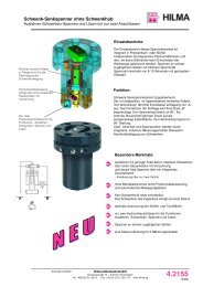
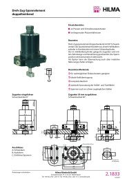
<strong>W<strong>edge</strong></strong> clamp<br />
<strong>with</strong> safety step<br />
A high degree of safety:<br />
This design features a <strong>clamping</strong> bolt<br />
<strong>with</strong> an additional accommodation<br />
surface, which is parallel to the <strong>clamping</strong><br />
<strong>edge</strong>.<br />
Should the pressure drop<br />
(machine failure or standstill),<br />
the upper die will lower onto the safety<br />
step where it is safely held in position.<br />
Resistant to temperatures of up to 160°C<br />
(higher temperatures on request)<br />
n<br />
h<br />
Lubricating nipple<br />
m<br />
i<br />
k<br />
b<br />
Øo<br />
d<br />
Max. stroke<br />
Max. <strong>clamping</strong> stroke<br />
l<br />
y<br />
v<br />
Tolerance only<br />
applies to Ø c H7<br />
0,5<br />
w<br />
p<br />
20°±0,2°<br />
s<br />
Ø u<br />
Ø t<br />
Ø c<br />
For bushing<br />
DIN 179<br />
f<br />
Safety<br />
step<br />
20°<br />
a<br />
e<br />
0,5<br />
v<br />
w<br />
A<br />
B<br />
max. 3 y<br />
max. stroke<br />
+5 mm<br />
* In the case of the 25 kN version,<br />
the lubricating nipples protrude<br />
by 5 mm and are offset by 9.5 mm<br />
Preferably to be used on the slide!<br />
*Clamping <strong>for</strong>ce **permissible retention <strong>for</strong>ce (<strong>for</strong> details, see 2-2400, page 2)<br />
Max. <strong>clamping</strong> <strong>for</strong>ce* (kN) 25 50 100 160 250 400 630<br />
Perm. operating pressure** (kN) 35 65 130 210 320 520 820<br />
Screw property class 8.8<br />
Max. operating pressure (bar) 350 275 350 350 350 350 350<br />
Cylinder Ø (mm) 25 40 50 63 80 100 125<br />
Max. stroke (mm) 20 25 25 30 32 40 40<br />
Clamping stroke (mm) 15 - 18 18 - 22 19 - 22 23 - 27 24 - 29 30 - 36 30 - 36<br />
Max. oil consumption (cm3) 10 31 49 94 161 314 491<br />
a (mm) 122 157 190 227 267 310 375<br />
b (mm) 58 78 100 125 150 180 225<br />
Ø c H7 x depth (mm) 18/7 26/9 30/11 35/11 48/13 55/16 62/16<br />
d (mm) 38 46 58 75 78 95 108<br />
e (mm) 14 16 20 25 26 32 38<br />
f (mm) 70 95 120 150 200 240 280<br />
g (mm) 48 65 85 106 140 180 210<br />
h (mm) 65 85 100 125 160 200 230<br />
i (mm) 111 146 177 210 246 285 344<br />
k (mm) 76 102 127 151 184 215 272<br />
l (mm) 20 25 26 32 40 45 50<br />
m (mm) G 1/4 G 1/4 G 1/4 G 1/2 G 1/2 G 1/2 G 1/2<br />
n (mm) 45 63 75 95 120 150 180<br />
Ø o (mm) 30 40 55 70 80 100 125<br />
p (mm) 21,5 28 37 49 55 75 85<br />
r (mm) 48 65 80 105 125 160 190<br />
s (mm) 13 18 20 26 32 38 44<br />
Ø t (mm) 13 17 21 26 33 39 45<br />
Ø u (mm) 20 26 32 40 48 57 66<br />
v (mm) 15 18 25 30 30 50 60<br />
w (mm) 17,5 21,2 28,2 34,7 35,8 57,8 67,8<br />
y (mm) 7 9 10 14 14 20 21<br />
Screw DIN 912-8.8 (4 pcs.) M 12 M 16 M 20 M 24 M 30 M 36 M 42<br />
Tightening torque (Nm) 86 210 410 710 1450 2520 4050<br />
Weight (kg) 2,4 5,8 10,6 21 40 74 125<br />
Part no. 8.2403.1000 8.2404.1000 8.2405.1000 8.2406.1000 8.2407.1000 8.2408.1000 8.2409.1000<br />
Accessories<br />
Bushings DIN 179 12 x 12 17 x 16 21 x 20 26 x 20 32 x 25 38 x 30 44 x 30<br />
Part no. 3300 285 3300 287 3300 288 3300 289 3300 420 3300 430 3300 440<br />
Subject to technical modification<br />
Hilma-Römheld GmbH<br />
Schützenstraße 74 · D-57271 Hilchenbach<br />
Phone +49 (0) 2733 / 281-0 · Fax +49 (0) 2733 / 281-113 · www.hilma.de<br />
2.24003<br />
03/2006