Wedge clamps for dies with tapered clamping edge Wedge clamps ...
Wedge clamps for dies with tapered clamping edge Wedge clamps ...
Wedge clamps for dies with tapered clamping edge Wedge clamps ...

You also want an ePaper? Increase the reach of your titles
YUMPU automatically turns print PDFs into web optimized ePapers that Google loves.
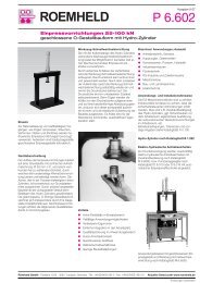
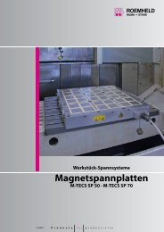
<strong>W<strong>edge</strong></strong> <strong>clamps</strong> <strong>for</strong> <strong>dies</strong><br />
<strong>with</strong> <strong>tapered</strong><br />
<strong>clamping</strong> <strong>edge</strong><br />
Without position monitoring<br />
up to 160°C*<br />
2.2400<br />
A<br />
B<br />
With position monitoring<br />
lateral fastening<br />
up to 100°C**<br />
A<br />
B<br />
2.24001<br />
With position monitoring<br />
rear side fastening<br />
up to 120°C**<br />
A<br />
B<br />
2.24002<br />
With safety step<br />
up to 160°C*<br />
2.24003<br />
A<br />
B<br />
With safety step<br />
+ position monitoring<br />
up to 100°C**<br />
A<br />
B<br />
2.24004<br />
With locking bolt<br />
up to 160°C*<br />
E<br />
2.24005<br />
A<br />
B<br />
With locking bolt<br />
+ position monitoring<br />
up to 100°C**<br />
A<br />
E<br />
B<br />
2.24006<br />
With sequence valve control<br />
up to 160°C*<br />
2.24007<br />
C A B<br />
With sequence valve control<br />
+ safety step<br />
up to 160°C*<br />
C A B<br />
2.24008<br />
With flanged directional<br />
seat valves<br />
up to 100°C**<br />
A<br />
A A<br />
A B<br />
Y1<br />
B<br />
B<br />
A A<br />
A B<br />
2.24009<br />
Y2<br />
B<br />
PR<br />
PR<br />
P<br />
R<br />
P<br />
R<br />
<strong>W<strong>edge</strong></strong> <strong>clamps</strong> <strong>for</strong> <strong>dies</strong><br />
<strong>with</strong> flat <strong>clamping</strong> <strong>edge</strong><br />
(*250°C on request)<br />
Without position monitoring<br />
up to 160°C<br />
2.2450<br />
A<br />
B<br />
With position monitoring<br />
up to 100°C**<br />
2.2460<br />
A<br />
(** 120°C <strong>for</strong> 1000 working hours)<br />
B<br />
Subject to technical modification<br />
Hilma-Römheld GmbH<br />
Schützenstraße 74 · D-57271 Hilchenbach<br />
Phone +49 (0) 2733 / 281-0 · Fax +49 (0) 2733 / 281-113 · www.hilma.de<br />
2.2400<br />
03/2006
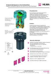
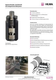
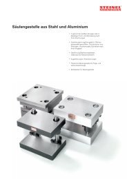
<strong>W<strong>edge</strong></strong> clamp, double-acting<br />
<strong>for</strong> <strong>dies</strong> <strong>with</strong> <strong>tapered</strong> <strong>clamping</strong> <strong>edge</strong><br />
Application:<br />
safe <strong>clamping</strong> of <strong>dies</strong> <strong>with</strong> a <strong>tapered</strong> <strong>clamping</strong> <strong>edge</strong><br />
<strong>for</strong> <strong>clamping</strong> of <strong>dies</strong> on a press bed and slide<br />
<strong>for</strong> <strong>clamping</strong> of <strong>dies</strong> in injection moulding machines<br />
A<br />
B<br />
Hardened w<strong>edge</strong> <strong>clamping</strong> insert<br />
Bushings<br />
Design:<br />
Double-acting w<strong>edge</strong> clamp <strong>for</strong> <strong>clamping</strong> <strong>dies</strong> on a<br />
press bed or slide or <strong>for</strong> <strong>clamping</strong> <strong>dies</strong> in injection<br />
moulding machines.<br />
The w<strong>edge</strong> clamp consists of a hydraulic block<br />
cylinder and a piston guided in a housing.<br />
The <strong>clamping</strong> bolt is provided <strong>with</strong> 20° bevel to clamp<br />
on the bevelled <strong>clamping</strong> surface of the die.<br />
Based on the internal design of the w<strong>edge</strong> clamp<br />
and the 20° <strong>clamping</strong> bevel the system is providing<br />
internal friction. For reasons of safety and in order<br />
to comply <strong>with</strong> the specifications of the ‘Machinery’<br />
directive no. ML98/37/EG, hydraulic pressure must<br />
always be maintained.<br />
When upper <strong>dies</strong> are clamped by w<strong>edge</strong> <strong>clamps</strong>,<br />
they must be secured mechanically when maintenance<br />
work is carried out.<br />
Retrofit: In many cases, existing <strong>dies</strong> can be standardised<br />
by adding w<strong>edge</strong> inserts. Max. hardness: 50 HRc.<br />
The occurring transverse <strong>for</strong>ces must be absorbed by<br />
bushings to be drilled into the fixture plate (see table <strong>for</strong><br />
accessories)<br />
Please note:<br />
In case of incorrect operation of the w<strong>edge</strong> <strong>clamping</strong><br />
element, the <strong>clamping</strong> bolt may fully retract into the guide<br />
housing and thus cause the upper die falling off the slide.<br />
Special features:<br />
available in sizes between 25 kN and 1250 kN<br />
high functional reliability ensured by position monitoring<br />
and an automatic cycle<br />
rugged and well-proven <strong>clamping</strong> element <strong>with</strong> high<br />
degree of safety and long service life<br />
The greasing intervals (high-temperature grease) should<br />
be scheduled in accordance <strong>with</strong> the operating conditions.<br />
Greasing of the <strong>clamping</strong> bolt should only be made<br />
<strong>with</strong> the elements being retracted.<br />
Clamping elements <strong>with</strong> w<strong>edge</strong> <strong>clamping</strong> bolt must be<br />
protected against dirt, scale, swarf, coolant, etc. by means<br />
of a suitable covering.<br />
Dies clamped by means of w<strong>edge</strong> <strong>clamping</strong> elements are<br />
subject to transverse <strong>for</strong>ces which may be strong enough<br />
to displace them. There<strong>for</strong>e, location pins or suitable limit<br />
stops should be provided, in order to keep the <strong>dies</strong> in their<br />
correct position.<br />
When using w<strong>edge</strong> <strong>clamping</strong> elements on the press slide,<br />
it is recommended that multiple-circuit hydraulic supply<br />
of the <strong>clamping</strong> elements and pilot-controlled check valves<br />
are used in the <strong>clamping</strong> lines <strong>for</strong> securing hydraulic<br />
<strong>clamping</strong>.<br />
Clamping circuit<br />
Safety circuit<br />
Un<strong>clamping</strong> circuit<br />
Principle of die <strong>clamping</strong><br />
In general, <strong>dies</strong> <strong>with</strong> round geometry are clamped using three<br />
<strong>clamping</strong> elements <strong>for</strong> each half, whereas <strong>dies</strong> <strong>with</strong> square or<br />
rectangular geometry are clamped using four <strong>clamping</strong> elements<br />
<strong>for</strong> each half<br />
Subject to technical modification<br />
Hilma-Römheld GmbH<br />
2.2400 Schützenstraße 74 · D-57271 Hilchenbach<br />
1<br />
03/2006<br />
Phone +49 (0) 2733 / 281-0 · Fax +49 (0) 2733 / 281-113 · www.hilma.de
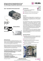
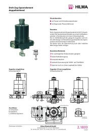
<strong>W<strong>edge</strong></strong> clamp, double-acting<br />
<strong>with</strong>out position monitoring<br />
<strong>W<strong>edge</strong></strong> clamp, double-acting<br />
<strong>for</strong> <strong>dies</strong> <strong>with</strong> <strong>tapered</strong> <strong>clamping</strong> <strong>edge</strong><br />
Clamping bolt <strong>with</strong> 20°chamfer,<br />
design <strong>with</strong>out proximity switch<br />
Resistant to temperatures of up to 160°C<br />
(<strong>for</strong> higher temperatures, please consult us)<br />
A<br />
B<br />
h n<br />
Lubricating nipple<br />
m<br />
i<br />
k<br />
b<br />
Øo<br />
d<br />
l<br />
Max. stroke<br />
e<br />
* In the case of the 25 kN version,<br />
a<br />
the lubricating nipples protrude<br />
by 5 mm and are offset by 9.5 mm<br />
* Clamping <strong>for</strong>ce<br />
This is the <strong>for</strong>ce that the <strong>clamping</strong> element applies to the workpiece at maximum operating pressure. The die is clamped on the fixture<br />
plate by means of this <strong>for</strong>ce. Under normal conditions, the external <strong>for</strong>ces acting on the die (i.e. the ejecting <strong>for</strong>ce or die cushion <strong>for</strong>ce)<br />
shall not exceed the totality of the <strong>clamping</strong> <strong>for</strong>ces of the elements.<br />
** Perm. retention <strong>for</strong>ce<br />
This is the holding power of <strong>clamping</strong> element and fastener (screw property class 8.8.). The above data is based on the condition that<br />
the appropriate tightening torque has been applied, and that material and geometry of the fixtures are suitable <strong>for</strong> the purpose. It must<br />
be ensured that in cases of emergency, e.g. workpiece jammed in the die, the totality of the retention <strong>for</strong>ces of the elements is not<br />
exceeded.<br />
v<br />
3 max.<br />
g ±0,02<br />
Tolerance applies<br />
to Ø c H7 only<br />
Max. <strong>clamping</strong> stroke<br />
w<br />
p<br />
20°±0,2°<br />
s<br />
Ø u<br />
Ø t<br />
Ø c<br />
For bushing<br />
DIN 179<br />
f<br />
Max. <strong>clamping</strong> <strong>for</strong>ce * (kN) 25 50 100 160 250 400 630<br />
Perm. retention <strong>for</strong>ce** (kN) 35 65 130 210 320 520 820<br />
Screw property class 8.8<br />
Max. operating pressure (bar) 350 275 350 350 350 350 350<br />
Cylinder-Ø (mm) 25 40 50 63 80 100 125<br />
Max. stroke (mm) 20 25 25 30 32 40 40<br />
Clamping stroke (from/to) (mm) 15 - 18 18 - 22 19 - 22 23 - 27 24 - 29 30 - 36 30 - 36<br />
Max. oil consumption (cm3) 10 31 49 94 161 314 491<br />
a (mm) 122 157 190 227 267 310 375<br />
b (mm) 58 78 100 125 150 180 225<br />
Ø c H7 x depth (mm) 18/7 26/9 30/11 35/11 48/13 55/16 62/16<br />
d (mm) 38 46 58 75 78 95 108<br />
e (mm) 14 16 20 25 26 32 38<br />
f (mm) 70 95 120 150 200 240 280<br />
g (mm) 48 65 85 106 140 180 210<br />
h (mm) 65 85 100 125 160 200 230<br />
i (mm) 111 146 177 210 246 285 344<br />
k (mm) 76 102 127 151 184 215 272<br />
l (mm) 20 25 26 32 40 45 50<br />
m (mm) G 1/4 G 1/4 G 1/4 G 1/2 G 1/2 G 1/2 G 1/2<br />
n (mm) 45 63 75 95 120 150 180<br />
Ø o (mm) 30 40 55 70 80 100 125<br />
p (mm) 21,5 28 37 49 55 75 85<br />
r (mm) 48 65 80 105 125 160 190<br />
s (mm) 13 18 20 26 32 38 44<br />
Ø t (mm) 13 17 21 26 33 39 45<br />
Ø u (mm) 20 26 32 40 48 57 66<br />
v (mm) 15 18 25 30 30 50 60<br />
w (mm) 19,5 23,5 30,5 37 38 60 70<br />
Screw DIN 912-8.8 (4 pieces) M 12 M 16 M 20 M 24 M 30 M 36 M 42<br />
Tightening torque (Nm) 86 210 410 710 1450 2520 4050<br />
Weight (kg) 2,4 5,8 10,6 21 40 74 125<br />
Part no. 4604 620 4604 621 4604 622 4604 623 4604 634 4604 635 4604 636<br />
Accessories<br />
Bushings DIN 179 12 x 12 17 x 16 21 x 20 26 x 20 32 x 25 38 x 30 44 x 30<br />
Part no. 3300 285 3300 287 3300 288 3300 289 3300 420 3300 430 3300 440<br />
Subject to technical modification<br />
2<br />
Hilma-Römheld GmbH<br />
Schützenstraße 74 · D-57271 Hilchenbach<br />
Phone +49 (0) 2733 / 281-0 · Fax +49 (0) 2733 / 281-113 · www.hilma.de<br />
2.2400<br />
03/2006
h<br />
r<br />
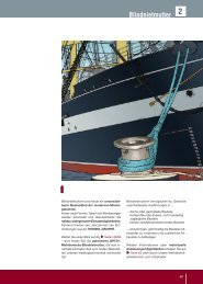
<strong>W<strong>edge</strong></strong> clamp, double-acting<br />
<strong>with</strong> position monitoring (lateral fastening)<br />
The inductive proximity switches are installed<br />
in the guide housing. They are activated<br />
by the <strong>clamping</strong> bolt. The contact areas are<br />
designed in such a way that one signal each<br />
is provided <strong>for</strong> the bolt in its initial position<br />
and <strong>for</strong> the bolt in the <strong>clamping</strong> position.<br />
Resistant to temperatures of up to 100°C.<br />
Cable length: 250 mm<br />
4-pole plug<br />
Pin assignment <strong>for</strong> three-wire proximity<br />
switches:<br />
2 = white, S2<br />
1 = brown +<br />
3 = blue -<br />
n<br />
Lubricating nipple<br />
m<br />
i<br />
k<br />
b<br />
Øo<br />
d<br />
Max. stroke<br />
Max. <strong>clamping</strong> stroke<br />
l<br />
v<br />
3 max.<br />
Tolerance applies<br />
to Ø c H7 only<br />
w<br />
p<br />
20°±0,2°<br />
Plug<br />
M 12 x 1<br />
4 poles<br />
s<br />
Ø u<br />
Ø t<br />
Ø c<br />
For bushing<br />
DIN 179<br />
Cable length: 250 mm<br />
f<br />
x<br />
Position<br />
monitoring<br />
4 = black, S1<br />
a<br />
S1<br />
S2<br />
e<br />
x<br />
* In the case of the 25 kN version,<br />
the lubricating nipples protrude<br />
by 5 mm and are offset by 9.5 mm<br />
Connecting lead <strong>with</strong> screw coupling:<br />
cable length 5 m part no. 5700013<br />
cable length 10 m part no. 5700014<br />
* Clamping <strong>for</strong>ce ** Perm. retention <strong>for</strong>ce (<strong>for</strong> details, please see 2.2400, page 2), 120°C <strong>for</strong> 1000 working hours.<br />
Max. <strong>clamping</strong> <strong>for</strong>ce * (kN) 25 50 100 160 250 400 630<br />
Perm. retention <strong>for</strong>ce** (kN) 35 65 130 210 320 520 820<br />
Screw property class 8.8<br />
Max. operating pressure (bar) 350 275 350 350 350 350 350<br />
Cylinder-Ø (mm) 25 40 50 63 80 100 125<br />
Max. stroke (mm) 20 25 25 30 32 40 40<br />
Clamping stroke (from/to) (mm) 15 - 18 18 - 22 19 - 22 23 - 27 24 - 29 30 - 36 30 - 36<br />
Max. oil consumption (cm3) 10 31 49 94 161 314 491<br />
a (mm) 122 157 190 227 267 310 375<br />
b (mm) 58 78 100 125 150 180 225<br />
Ø c H7 x depth (mm) 18/7 26/9 30/11 35/11 48/13 55/16 62/16<br />
d (mm) 38 46 58 75 78 95 108<br />
e (mm) 14 16 20 25 26 32 38<br />
f (mm) 70 95 120 150 200 240 280<br />
g (mm) 48 65 85 106 140 180 210<br />
h (mm) 65 85 100 125 160 200 230<br />
i (mm) 111 146 177 210 246 285 344<br />
k (mm) 76 102 127 151 184 215 272<br />
l (mm) 20 25 26 32 40 45 50<br />
m (mm) G 1/4 G 1/4 G 1/4 G 1/2 G 1/2 G 1/2 G 1/2<br />
n (mm) 45 63 75 95 120 150 180<br />
Ø o (mm) 30 40 55 70 80 100 125<br />
p (mm) 21,5 28 37 49 55 75 85<br />
r (mm) 48 65 80 105 125 160 190<br />
s (mm) 13 18 20 26 32 38 44<br />
Ø t (mm) 13 17 21 26 33 39 45<br />
Ø u (mm) 20 26 32 40 48 57 66<br />
v (mm) 15 18 25 30 30 50 60<br />
w (mm) 19,5 23,5 30,5 37 38 60 70<br />
x (mm) 12 5 0 0 0 0 0<br />
Screw DIN 912-8.8 (4 pieces) M 12 M 16 M 20 M 24 M 30 M 36 M 42<br />
Tightening torque (Nm) 86 210 410 710 1450 2520 4050<br />
Weight (kg) 2,4 5,8 10,6 21 40 74 125<br />
Part no. 8.2403.0500 8.2404.0500 8.2405.0500 8.2406.0500 8.2407.0500 8.2408.0500 8.2409.0500<br />
Accessories<br />
Bushings DIN 179 12 x 12 17 x 16 21 x 20 26 x 20 32 x 25 38 x 30 44 x 30<br />
Part no. 3300 285 3300 287 3300 288 3300 289 3300 420 3300 430 3300 440<br />
2.24001<br />
03/2006<br />
Hilma-Römheld GmbH<br />
Schützenstraße 74 · D-57271 Hilchenbach<br />
Phone +49 (0) 2733 / 281-0 · Fax +49 (0) 2733 / 281-113 · www.hilma.de<br />
Subject to technical modification
<strong>W<strong>edge</strong></strong> clamp,<br />
<strong>with</strong> position monitoring (rear side fastening)<br />
<strong>W<strong>edge</strong></strong> clamp <strong>with</strong> adjustable<br />
electronic position monitoring,<br />
rear side fastening.<br />
Inductive proximity switches installed in the<br />
flanged housing. The proximity switches<br />
are activated by a trip cam which is<br />
connected to the piston rod.<br />
The switches can be displaced in a slot.<br />
The housing can be turned through 180°.<br />
Position monitoring is available<br />
in 3 versions:<br />
- as a compact version <strong>for</strong> M8 plug<br />
- as a rugged long version <strong>for</strong> M12 plug<br />
- as a version <strong>for</strong> high temperatures<br />
up to 120°C<br />
<strong>with</strong> fitted cable (L = 5 m).<br />
Technical data <strong>for</strong> position monitoring<br />
Operating voltage: 10 ... 30 V DC<br />
Constant current: 200 mA<br />
Tripping function: NO<br />
Type:<br />
PNP<br />
Nominal tripping distance: 1.5 mm<br />
Ambient temperature: -25 +70°C<br />
Variante C up to +120°C<br />
Protective system: IP 67<br />
Standard:<br />
Version A<br />
Compact<br />
version<br />
<strong>for</strong> M8 plug<br />
45<br />
50<br />
Version B<br />
Rugged long<br />
version, sensor<br />
<strong>for</strong> M12 plug<br />
Position<br />
monitoring<br />
S1 M8 S2<br />
M12<br />
Trip cam<br />
n<br />
a1<br />
m<br />
Block cylinder<br />
a<br />
Version C<br />
For high<br />
temperatures<br />
up to 120 ºC<br />
<strong>with</strong> fitted<br />
cable<br />
(L = 5 m)<br />
i<br />
k<br />
Ø o<br />
Guide housing<br />
d<br />
b<br />
The position monitoring unit can turned through 180º (90º on request)<br />
The block cylinder can be turned through 180°<br />
Max. stroke<br />
l<br />
e<br />
g ±0,02<br />
v<br />
3 max.<br />
Tolerance<br />
only valid <strong>for</strong> Ø c H7<br />
w<br />
20°<br />
Lubricating nipple<br />
s<br />
Ø u<br />
Ø t<br />
Ø c<br />
h<br />
f<br />
For bushing<br />
DN 179<br />
* In the case of Ø 30 mm<br />
bolts the lubricating nipples protrude<br />
by 5 mm and are offset by 9.5 mm<br />
Fixed cable<br />
Adjusting<br />
<strong>edge</strong><br />
* Clamping <strong>for</strong>ce ** Permanent retention <strong>for</strong>ce (Explanations see 2.2400 page 2)<br />
Max. <strong>clamping</strong> <strong>for</strong>ce * (kN) 25 50 100 160 250 400 630<br />
Perm. retention <strong>for</strong>ce** (kN) 35 65 130 210 320 520 820<br />
Screw property class 8.8<br />
Max. operating pressure (bar) 350 275 350 350 350 350 350<br />
Cylinder Ø (mm) 25 40 50 63 80 100 125<br />
Max. stroke (mm) 20 25 25 30 32 40 40<br />
Clamping stroke (mm) 15-18 18-22 19-22 23-27 24-29 30-36 30-36<br />
a (mm) 134 168 200 235 270 310 375<br />
a1 (mm) 184 218 250 285 330 370 435<br />
b (mm) 58 78 100 125 150 180 225<br />
Ø c H7 x depth (mm) 18/7 26/9 30/11 35/11 48/13 55/16 62/16<br />
d (mm) 38 46 58 75 78 95 108<br />
e (mm) 14 16 20 25 26 32 38<br />
f (mm) 70 95 120 150 200 240 280<br />
g (mm) 48 65 85 106 140 180 210<br />
h (mm) 65 85 100 125 160 200 230<br />
i (mm) 111 146 177 210 246 285 344<br />
k (mm) 76 102 127 151 184 215 272<br />
l (mm) 20 25 26 32 40 45 50<br />
m (connecting thread) (mm) (4x) G 1/4 (4x) G 1/4 (4x) G 1/4 (4x) G 1/2 (2x) G 1/2 (2x) G 1/2 (2x) G 1/2<br />
n (mm) 45 63 75 95 120 150 180<br />
Ø o (mm) 30 40 55 70 80 100 125<br />
p (mm) 21,5 28 37 49 55 75 85<br />
r (mm) 48 65 80 105 125 160 190<br />
s (mm) 13 18 20 26 32 38 44<br />
Ø t (mm) 13 17 21 26 33 39 45<br />
Ø u (mm) 20 26 32 40 48 57 66<br />
v (mm) 15 18 25 30 30 50 60<br />
w (mm) 19,5 23,5 30,5 37 38 60 70<br />
Screw DIN 912-8.8 (4 pieces) M 12 M 16 M 20 M 24 M 30 M 36 M 42<br />
Tightening torque (Nm) 86 210 410 710 1450 2520 4050<br />
Weight (kg) 3,0 6,5 11,4 21,7 41 74,7 126<br />
Part no. 4604 670 4604 671 4604 672 4604 673 4604 674 4604 675 4604 676<br />
Always add the desired sensor version to the part no., e.g., 4604 670 B<br />
Accessories Bushings DIN 179 12 x 12 17 x 16 21 x 20 26 x 20 32 x 25 38 x 30 44 x 30<br />
Part no. 3300 285 3300 287 3300 288 3300 289 3300 420 3300 430 3300 440<br />
Subject to technical modification<br />
Hilma-Römheld GmbH<br />
1 2.24002<br />
Schützenstraße 74 · D-57271 Hilchenbach<br />
Phone +49 (0) 2733 / 281-0 · Fax +49 (0) 2733 / 281-113 · www.hilma.de<br />
03/2006
Technical details of accessories:<br />
Adjustable position monitoring <strong>for</strong> w<strong>edge</strong> <strong>clamps</strong><br />
Description<br />
The position monitoring unit is fixed to the<br />
cylinder bottom by means of screws. It can<br />
be fastened in a position turned by 180°.<br />
Various versions are available to suit different<br />
applications. The trip cam <strong>for</strong> activating the<br />
proximity switches is positioned on the<br />
continuous piston rod. The tripping position<br />
is adjusted by displacing the proximity<br />
switches in the lateral slot. The proximity<br />
switches are activated by the trip cam <strong>with</strong>in<br />
a stroke of approx. 6 mm.<br />
The minimum distance of the tripping<br />
positions depends on the type of switch<br />
and is indicated in the table.<br />
Function<br />
1. Function message of the unclamped<br />
position, i.e. the piston rod has retracted.<br />
2. Message of the clamped position, i.e.<br />
the piston rod has extended and is in<br />
the <strong>clamping</strong> range.<br />
Wiring diagram<br />
1 brown<br />
4 black<br />
3 blue<br />
+<br />
-<br />
Important in<strong>for</strong>mation<br />
The position monitoring unit is not suitable<br />
<strong>for</strong> use in areas <strong>with</strong> coolant. Also, additional<br />
covers must be provided to protect the<br />
system from any swarf.<br />
Planning - Conditions of application -<br />
Protective measures<br />
Careful planning is of great importance. The<br />
conditions of application and the protective<br />
measures must be taken into consideration<br />
and ensured.<br />
Please contact us <strong>for</strong> more detailed<br />
in<strong>for</strong>mation.<br />
Technical data of inductive<br />
proximity switches<br />
Version A (standard)<br />
Compact version M8<br />
Version B<br />
Long version M12<br />
Version C<br />
High ambient<br />
temperatures<br />
Operating voltage: 10 ... 30 V DC<br />
Residual ripple: max. 15%<br />
Tripping function: NO<br />
Type:<br />
PNP<br />
Material of housing: corrosion-proof<br />
steel<br />
Protective system<br />
(DIN 40050): IP 67<br />
L1<br />
45<br />
Adjusting<br />
<strong>edge</strong><strong>for</strong><br />
preadjustment<br />
of initiators<br />
50 27<br />
LED<br />
Adjusting<br />
<strong>edge</strong> <strong>for</strong><br />
preadjustment<br />
of initiators<br />
50<br />
LED<br />
58<br />
Adjusting<br />
<strong>edge</strong> <strong>for</strong><br />
preadjustment<br />
of initiators<br />
50 39<br />
Ambient temperature TA -25° ... +70°C -25° ... +70°C -25° ... +120°C<br />
Min. distance of tripping position (mm) 8 13 8<br />
Type of connection plug plug Teflon cable 3 x 0.14 mm 2<br />
LED visualisation of function in the plug yes no<br />
Max. constant currrent (mA) 200 200 200 - (from 70°C) 100<br />
Nominal tripping distance (mm) 1.5 1.5 2<br />
Short-circuit proof yes yes no<br />
Connecting cable (m) 5 5 3<br />
Proximity switch Part no. 6.3829.0980 2.5012.0064 6.3829.0870<br />
Plug <strong>with</strong> cable Part no. 3829099 2.0975.0024 fixed<br />
L1 complete (mm) 50 50 50<br />
Position monitoring<br />
up to 30 mm total stroke Part no. 7.6282.0010 A 7.6282.0010 B 7.6282.0010 C<br />
(<strong>with</strong>out a plug)<br />
up to type 4604 673<br />
L1 complete (mm) 60 60 60<br />
Position monitoring<br />
up to 50 mm total stroke Part no. 7.6282.0011 A 7.6282.0011 B 7.6282.0011 C<br />
(<strong>with</strong>out a plug)<br />
from type 4604 674<br />
2.24002<br />
03/2006<br />
Hilma-Römheld GmbH<br />
Schützenstraße 74 · D-57271 Hilchenbach<br />
Phone +49 (0) 2733 / 281-0 · Fax +49 (0) 2733 / 281-113 · www.hilma.de<br />
Subject to technical modification<br />
2
<strong>W<strong>edge</strong></strong> clamp<br />
<strong>with</strong> safety step<br />
A high degree of safety:<br />
This design features a <strong>clamping</strong> bolt<br />
<strong>with</strong> an additional accommodation<br />
surface, which is parallel to the <strong>clamping</strong><br />
<strong>edge</strong>.<br />
Should the pressure drop<br />
(machine failure or standstill),<br />
the upper die will lower onto the safety<br />
step where it is safely held in position.<br />
Resistant to temperatures of up to 160°C<br />
(higher temperatures on request)<br />
n<br />
h<br />
Lubricating nipple<br />
m<br />
i<br />
k<br />
b<br />
Øo<br />
d<br />
Max. stroke<br />
Max. <strong>clamping</strong> stroke<br />
l<br />
y<br />
v<br />
Tolerance only<br />
applies to Ø c H7<br />
0,5<br />
w<br />
p<br />
20°±0,2°<br />
s<br />
Ø u<br />
Ø t<br />
Ø c<br />
For bushing<br />
DIN 179<br />
f<br />
Safety<br />
step<br />
20°<br />
a<br />
e<br />
0,5<br />
v<br />
w<br />
A<br />
B<br />
max. 3 y<br />
max. stroke<br />
+5 mm<br />
* In the case of the 25 kN version,<br />
the lubricating nipples protrude<br />
by 5 mm and are offset by 9.5 mm<br />
Preferably to be used on the slide!<br />
*Clamping <strong>for</strong>ce **permissible retention <strong>for</strong>ce (<strong>for</strong> details, see 2-2400, page 2)<br />
Max. <strong>clamping</strong> <strong>for</strong>ce* (kN) 25 50 100 160 250 400 630<br />
Perm. operating pressure** (kN) 35 65 130 210 320 520 820<br />
Screw property class 8.8<br />
Max. operating pressure (bar) 350 275 350 350 350 350 350<br />
Cylinder Ø (mm) 25 40 50 63 80 100 125<br />
Max. stroke (mm) 20 25 25 30 32 40 40<br />
Clamping stroke (mm) 15 - 18 18 - 22 19 - 22 23 - 27 24 - 29 30 - 36 30 - 36<br />
Max. oil consumption (cm3) 10 31 49 94 161 314 491<br />
a (mm) 122 157 190 227 267 310 375<br />
b (mm) 58 78 100 125 150 180 225<br />
Ø c H7 x depth (mm) 18/7 26/9 30/11 35/11 48/13 55/16 62/16<br />
d (mm) 38 46 58 75 78 95 108<br />
e (mm) 14 16 20 25 26 32 38<br />
f (mm) 70 95 120 150 200 240 280<br />
g (mm) 48 65 85 106 140 180 210<br />
h (mm) 65 85 100 125 160 200 230<br />
i (mm) 111 146 177 210 246 285 344<br />
k (mm) 76 102 127 151 184 215 272<br />
l (mm) 20 25 26 32 40 45 50<br />
m (mm) G 1/4 G 1/4 G 1/4 G 1/2 G 1/2 G 1/2 G 1/2<br />
n (mm) 45 63 75 95 120 150 180<br />
Ø o (mm) 30 40 55 70 80 100 125<br />
p (mm) 21,5 28 37 49 55 75 85<br />
r (mm) 48 65 80 105 125 160 190<br />
s (mm) 13 18 20 26 32 38 44<br />
Ø t (mm) 13 17 21 26 33 39 45<br />
Ø u (mm) 20 26 32 40 48 57 66<br />
v (mm) 15 18 25 30 30 50 60<br />
w (mm) 17,5 21,2 28,2 34,7 35,8 57,8 67,8<br />
y (mm) 7 9 10 14 14 20 21<br />
Screw DIN 912-8.8 (4 pcs.) M 12 M 16 M 20 M 24 M 30 M 36 M 42<br />
Tightening torque (Nm) 86 210 410 710 1450 2520 4050<br />
Weight (kg) 2,4 5,8 10,6 21 40 74 125<br />
Part no. 8.2403.1000 8.2404.1000 8.2405.1000 8.2406.1000 8.2407.1000 8.2408.1000 8.2409.1000<br />
Accessories<br />
Bushings DIN 179 12 x 12 17 x 16 21 x 20 26 x 20 32 x 25 38 x 30 44 x 30<br />
Part no. 3300 285 3300 287 3300 288 3300 289 3300 420 3300 430 3300 440<br />
Subject to technical modification<br />
Hilma-Römheld GmbH<br />
Schützenstraße 74 · D-57271 Hilchenbach<br />
Phone +49 (0) 2733 / 281-0 · Fax +49 (0) 2733 / 281-113 · www.hilma.de<br />
2.24003<br />
03/2006
2.24004<br />
n<br />
h<br />
m<br />
r<br />
<strong>W<strong>edge</strong></strong> clamp<br />
<strong>with</strong> safety step + position monitoring<br />
A high degree of safety:<br />
This design features a <strong>clamping</strong> bolt<br />
<strong>with</strong> an additional accommodating<br />
surface which is parallel to the<br />
<strong>clamping</strong> <strong>edge</strong>. Should the pressure<br />
drop (machine failure or standstill),<br />
the upper die will lower onto the safety<br />
step where it is safely held in position.<br />
Resistant to temperatures of up to 100°C***<br />
Cable length: 250 mm<br />
4-pole plug<br />
Pin assignment:<br />
2 = white, S2<br />
1 = brown +<br />
03/2006<br />
3 = blue -<br />
Plug<br />
4 = black, S1<br />
M 12 x 1<br />
4-pole<br />
Connecting lead <strong>with</strong> screw coupling:<br />
Cable length 5 m - part no. 5700013<br />
Cable length 10 m - part no. 5700014<br />
Cable length: 250 mm<br />
Lubricating nipple<br />
i<br />
a<br />
S1<br />
k<br />
b<br />
S2<br />
Øo<br />
d<br />
l<br />
Max. stroke<br />
e<br />
y<br />
g ±0,02<br />
x<br />
Max. <strong>clamping</strong> stroke<br />
Hilma-Römheld GmbH<br />
Schützenstraße 74 · D-57271 Hilchenbach<br />
Phone +49 (0) 2733 / 281-0 · Fax +49 (0) 2733 / 281-113 · www.hilma.de<br />
v<br />
0,5<br />
w<br />
p<br />
20°±0,2°<br />
s<br />
Ø u<br />
Ø t<br />
Ø c<br />
For bushing<br />
DIN 179<br />
max. 3 y<br />
max. stroke<br />
+5 mm<br />
*Clamping <strong>for</strong>ce **permissible retention <strong>for</strong>ce (<strong>for</strong> details, see 2.2400, page 2), *** 120°C <strong>for</strong> 1000 working hours<br />
Max. <strong>clamping</strong> <strong>for</strong>ce* (kN) 25 50 100 160 250 400 630<br />
Perm. operating pressure** (kN) 35 65 130 210 320 520 820<br />
Screw property class 8.8<br />
Max. operating pressure (bar) 350 275 350 350 350 350 350<br />
Cylinder Ø (mm) 25 40 50 63 80 100 125<br />
Max. stroke (mm) 20 25 25 30 32 40 40<br />
Clamping stroke (mm) 15 - 18 18 - 22 19 - 22 23 - 27 24 - 29 30 - 36 30 - 36<br />
Max. oil consumption (cm3) 10 31 49 94 161 314 491<br />
a (mm) 122 157 190 227 267 310 375<br />
b (mm) 58 78 100 125 150 180 225<br />
Ø c H7 x depth (mm) 18/7 26/9 30/11 35/11 48/13 55/16 62/16<br />
d (mm) 38 46 58 75 78 95 108<br />
e (mm) 14 16 20 25 26 32 38<br />
f (mm) 70 95 120 150 200 240 280<br />
g (mm) 48 65 85 106 140 180 210<br />
h (mm) 65 85 100 125 160 200 230<br />
i (mm) 111 146 177 210 246 285 344<br />
k (mm) 76 102 127 151 184 215 272<br />
l (mm) 20 25 26 32 40 45 50<br />
m (mm) G 1/4 G 1/4 G 1/4 G 1/2 G 1/2 G 1/2 G 1/2<br />
n (mm) 45 63 75 95 120 150 180<br />
Ø o (mm) 30 40 55 70 80 100 125<br />
p (mm) 21,5 28 37 49 55 75 85<br />
r (mm) 48 65 80 105 125 160 190<br />
s (mm) 13 18 20 26 32 38 44<br />
Ø t (mm) 13 17 21 26 33 39 45<br />
Ø u (mm) 20 26 32 40 48 57 66<br />
v (mm) 15 18 25 30 30 50 60<br />
w (mm) 17,5 21,2 28,2 34,7 35,8 57,8 67,8<br />
x Position monitoring (mm) 12 5 0 0 0 0 0<br />
y (mm) 7 9 10 14 14 20 21<br />
Screw DIN 912-8.8 (4 pcs.) M 12 M 16 M 20 M 24 M 30 M 36 M 42<br />
Tightening torque (Nm) 86 210 410 710 1450 2520 4050<br />
Weight (kg) 2,4 5,8 10,6 21 40 74 125<br />
Part no. 8.2403.2000 8.2404.2000 8.2405.2000 8.2406.2000 8.2407.2000 8.2408.2000 8.2409.2000<br />
Accessories<br />
Bushings DIN 179 12 x 12 17 x 16 21 x 20 26 x 20 32 x 25 38 x 30 44 x 30<br />
Part no. 3300 285 3300 287 3300 288 3300 289 3300 420 3300 430 3300 440<br />
Tolerance only<br />
applies to Ø c H7<br />
* In the case of the 25 kN version,<br />
the lubricating nipples protrude<br />
by 5 mm and are offset by 9.5 mm<br />
f<br />
Safety<br />
x<br />
steps<br />
Position<br />
monitoring<br />
v<br />
0,5<br />
w<br />
Subject to technical modification<br />
20°
n<br />
Lubricating nipple<br />
m<br />
k<br />
i<br />
C<br />
Øo<br />
B<br />
v<br />
w<br />
p<br />
r<br />
<strong>W<strong>edge</strong></strong> <strong>clamps</strong><br />
<strong>with</strong> locking bolt<br />
<strong>W<strong>edge</strong></strong> <strong>clamps</strong> <strong>for</strong> maximum safety:<br />
The locking bolt of the w<strong>edge</strong> clamp<br />
is prevented from retracting using an<br />
additional locking cylinder. Only after<br />
the locking bolt has been unlocked<br />
can the <strong>clamping</strong> position be used.<br />
Resistant to temperatures of up to 160°C<br />
(higher temperatures on request)<br />
Max. stroke Locking bolt Ø u <strong>W<strong>edge</strong></strong> clamp<br />
l<br />
max. 3<br />
Max. <strong>clamping</strong> stroke<br />
20°±0,2°<br />
D<br />
G1/8<br />
hydraulic port,<br />
G1/4<br />
<strong>for</strong> 160 kN and above<br />
E<br />
s<br />
Ø t<br />
Ø c<br />
f<br />
For bushing<br />
DIN 179<br />
E<br />
A<br />
E<br />
h<br />
A<br />
B<br />
g ±0,02<br />
Tolerance only<br />
applies to Ø c H7<br />
A<br />
B<br />
a<br />
b<br />
d<br />
e<br />
* In the case of the 25 kN version,<br />
the lubricating nipples protrude<br />
by 5 mm and are offset by 9.5 mm<br />
*Clamping <strong>for</strong>ce **permissible retention <strong>for</strong>ce (<strong>for</strong> details, see 2.2400, page 2)<br />
Max. <strong>clamping</strong> <strong>for</strong>ce* (kN) 25 50 100 160 250 400 630<br />
Perm. operating pressure** (kN) 35 65 130 210 320 520 820<br />
Screw property class 8.8<br />
Max. operating pressure (bar) 350 275 350 350 350 350 350<br />
Cylinder Ø (mm) 25 40 50 63 80 100 125<br />
Max. stroke (mm) 20 25 25 30 32 40 40<br />
Clamping stroke (mm) 15 - 18 18 - 22 19 - 22 23 - 27 24 - 29 30 - 36 30 - 36<br />
Oil consumpt. <strong>clamping</strong>/unlocking (cm3) 10/3 31/3 49/3 94/2,5 161/2,5 314/2,5 491/2,5<br />
a (mm) 122 157 190 227 267 310 375<br />
b (mm) 58 78 100 125 150 180 225<br />
Ø c H7 x depth (mm) 18/7 26/9 30/11 35/11 48/13 55/16 62/16<br />
d (mm) 38 46 58 75 78 95 108<br />
e (mm) 14 16 20 25 26 32 38<br />
f (mm) 70 95 120 150 200 240 280<br />
g (mm) 48 65 85 106 140 180 210<br />
h (mm) 65 85 100 125 160 200 230<br />
i (mm) 111 146 177 210 246 285 344<br />
k (mm) 76 102 127 151 184 215 272<br />
l (mm) 20 25 26 32 40 45 50<br />
m (mm) G 1/4 G 1/4 G 1/4 G 1/2 G 1/2 G 1/2 G 1/2<br />
n (mm) 45 63 75 95 120 150 180<br />
Ø o (mm) 30 40 55 70 80 100 125<br />
p (mm) 21,5 28 37 49 55 75 85<br />
r (mm) 48 65 80 105 125 160 190<br />
s (mm) 13 18 20 26 32 38 44<br />
Ø t (mm) 13 17 21 26 33 39 45<br />
Ø u (mm) 20 26 32 40 48 57 66<br />
v (mm) 15 18 25 30 30 50 60<br />
w (mm) 19,5 23,5 30,5 37,0 38,0 60 70,0<br />
A (mm) 57,5 57,5 57,5 60 60 65 65<br />
B (mm) 27 44 66 94 119 144,5 189,5<br />
C (mm) 40 40 40 45 45 40 40<br />
D (mm) 48 58 67 89 95 110 120<br />
Screw DIN 912-8.8 (4 pcs.) M 12 M 16 M 20 M 24 M 30 M 36 M 42<br />
Tightening torque (Nm) 86 210 410 710 1450 2520 4050<br />
Weight (kg) 3,0 6,5 11,4 21,7 41 74,7 126<br />
Part no. 8.2403.1500 8.2404.1500 8.2405.1500 8.2406.1500 8.2407.1500 8.2408.1500 8.2409.1500<br />
Accessories<br />
Bushings DIN 179 12 x 12 17 x 16 21 x 20 26 x 20 32 x 25 38 x 30 44 x 30<br />
Part no. 3300 285 3300 287 3300 288 3300 289 3300 420 3300 430 3300 440<br />
Subject to technical modification<br />
Hilma-Römheld GmbH<br />
Schützenstraße 74 · D-57271 Hilchenbach<br />
Phone +49 (0) 2733 / 281-0 · Fax +49 (0) 2733 / 281-113 · www.hilma.de<br />
2.24005<br />
03/2006
<strong>W<strong>edge</strong></strong> clamp<br />
<strong>with</strong> locking bolt + position monitoring<br />
<strong>W<strong>edge</strong></strong> <strong>clamps</strong> <strong>for</strong> maximum safety:<br />
The locking bolt of the w<strong>edge</strong> clamp<br />
is prevented from retracting using an<br />
additional locking cylinder. Only after<br />
the locking bolt has been unlocked<br />
can the <strong>clamping</strong> position be used.<br />
Resistant to temperatures of up to 100°C***<br />
Cable length: 250 mm<br />
5-pole plug<br />
Pin assignment:<br />
n<br />
Lubricating nipple<br />
m<br />
k<br />
i<br />
C<br />
S3<br />
E<br />
Øo<br />
B<br />
G1/8 hydraulic port,<br />
Max. stroke<br />
G1/4 <strong>for</strong> 160 kN<br />
and above<br />
Ø u<br />
Max. <strong>clamping</strong> stroke<br />
E<br />
l<br />
A<br />
v<br />
w<br />
p<br />
20°±0,2°<br />
D<br />
Position<br />
monitoring<br />
of the locking bolt,<br />
unlocked position<br />
Locking bolt<br />
s<br />
Ø t<br />
Ø c<br />
f<br />
For bushing<br />
DIN 179<br />
<strong>W<strong>edge</strong></strong> clamp<br />
x<br />
Position<br />
monitoring<br />
2 = white, S2<br />
1 = brown +<br />
3 = blue -<br />
h<br />
A<br />
B<br />
g ±0,02<br />
Tolerance only<br />
applies to Ø c H7<br />
Plug<br />
M 12 x 1<br />
5-pole<br />
4 = black, S1<br />
*Clamping <strong>for</strong>ce **permissible retention <strong>for</strong>ce (<strong>for</strong> details, see 2.2400, page 2), *** 120°C <strong>for</strong> 1000 working hours<br />
2.24006<br />
03/2006<br />
5 = grey, S3<br />
a<br />
S1<br />
Hilma-Römheld GmbH<br />
Schützenstraße 74 · D-57271 Hilchenbach<br />
Phone +49 (0) 2733 / 281-0 · Fax +49 (0) 2733 / 281-113 · www.hilma.de<br />
b<br />
d<br />
S2<br />
e<br />
* In the case of the 25 kN version,<br />
the lubricating nipples protrude<br />
by 5 mm and are offset by 9.5 mm<br />
Max. <strong>clamping</strong> <strong>for</strong>ce* (kN) 25 50 100 160 250 400 630<br />
Perm. operating pressure** (kN) 35 65 130 210 320 520 820<br />
Screw property class 8.8<br />
Max. operating pressure (bar) 350 275 350 350 350 350 350<br />
Cylinder Ø (mm) 25 40 50 63 80 100 125<br />
Max. stroke (mm) 20 25 25 30 32 40 40<br />
Clamping stroke (mm) 15 - 18 18 - 22 19 - 22 23 - 27 24 - 29 30 - 36 30 - 36<br />
Oil consumpt. <strong>clamping</strong>/unlocking (cm3) 10/3 31/3 49/3 94/2,5 161/2,5 314/2,5 491/2,5<br />
a (mm) 122 157 190 227 267 310 375<br />
b (mm) 58 78 100 125 150 180 225<br />
Ø c H7 x depth (mm) 18/7 26/9 30/11 35/11 48/13 55/16 62/16<br />
d (mm) 38 46 58 75 78 95 108<br />
e (mm) 14 16 20 25 26 32 38<br />
f (mm) 70 95 120 150 200 240 280<br />
g (mm) 48 65 85 106 140 180 210<br />
h (mm) 65 85 100 125 160 200 230<br />
i (mm) 111 146 177 210 246 285 344<br />
k (mm) 76 102 127 151 184 215 272<br />
l (mm) 20 25 26 32 40 45 50<br />
m (mm) G 1/4 G 1/4 G 1/4 G 1/2 G 1/2 G 1/2 G 1/2<br />
n (mm) 45 63 75 95 120 150 180<br />
Ø o (mm) 30 40 55 70 80 100 125<br />
p (mm) 21,5 28 37 49 55 75 85<br />
r (mm) 48 65 80 105 125 160 190<br />
s (mm) 13 18 20 26 32 38 44<br />
Ø t (mm) 13 17 21 26 33 39 45<br />
Ø u (mm) 20 26 32 40 48 57 66<br />
v (mm) 15 18 25 30 30 50 60<br />
w (mm) 19,5 23,5 30,5 37,0 38,0 60 70,0<br />
x Position monitoring (mm) 12 5 0 0 0 0 0<br />
A (mm) 57,5 57,5 57,5 60 60 65 65<br />
B (mm) 27 44 66 94 119 144,5 189,5<br />
C (mm) 40 40 40 45 45 40 40<br />
D (mm) 48 58 67 89 95 110 120<br />
Screw DIN 912-8.8 (4 pcs.) M 12 M 16 M 20 M 24 M 30 M 36 M 42<br />
Tightening torque (Nm) 86 210 410 710 1450 2520 4050<br />
Weight (kg) 3,0 6,5 11,4 21,7 41 74,7 126<br />
Part no. 8.2403.3000 8.2404.3000 8.2405.3000 8.2406.3000 8.2407.3000 8.2408.3000 8.2409.3000<br />
Accessories<br />
Bushings DIN 179 12 x 12 17 x 16 21 x 20 26 x 20 32 x 25 38 x 30 44 x 30<br />
Part no. 3300 285 3300 287 3300 288 3300 289 3300 420 3300 430 3300 440<br />
Subject to technical modification
<strong>W<strong>edge</strong></strong> clamp<br />
<strong>with</strong> sequence valve control<br />
<strong>W<strong>edge</strong></strong> <strong>clamps</strong> <strong>with</strong> hydraulic position<br />
monitoring, suitable <strong>for</strong> high temperatures:<br />
An additional valve block on the standard<br />
w<strong>edge</strong> clamp enables hydraulic control of<br />
the <strong>clamping</strong> position. Only after the last<br />
w<strong>edge</strong> clamp has been clamped is the<br />
machine control released by a pressure<br />
switch on the pressure generator.<br />
n<br />
E<br />
F<br />
G<br />
Lubricating nipple Max. stroke<br />
Max. <strong>clamping</strong> stroke<br />
m<br />
l 3 max.<br />
k<br />
i<br />
Øo<br />
v<br />
w<br />
p<br />
20°±0,2°<br />
s<br />
Ø u<br />
Ø t<br />
Ø c<br />
f<br />
Resistant to temperatures of up to 160°C<br />
(higher temperatures on request)<br />
Sequence control<br />
b<br />
d<br />
For bushing<br />
DIN 179<br />
h<br />
H<br />
C<br />
g ±0,02<br />
Tolerance only<br />
applies to Ø c H7<br />
C A B<br />
A B<br />
e<br />
a<br />
A = Hydraulic port "<strong>clamping</strong>"<br />
B = Hydraulic port "un<strong>clamping</strong>"<br />
C = Hydraulic port "sequence valve"<br />
* In the case of the 25 kN version,<br />
the lubricating nipples protrude<br />
by 5 mm and are offset by 9.5 mm<br />
*Clamping <strong>for</strong>ce **permissible retention <strong>for</strong>ce (<strong>for</strong> details, see 2.2400, page 2)<br />
Max. <strong>clamping</strong> <strong>for</strong>ce* (kN) 25 50 100 160 250 400 630<br />
Perm. operating pressure** (kN) 35 65 130 210 320 520 820<br />
Screw property class 8.8<br />
Max. operating pressure (bar) 350 275 350 350 350 350 350<br />
Cylinder Ø (mm) 25 40 50 63 80 100 125<br />
Max. stroke (mm) 20 25 25 30 32 40 40<br />
Clamping stroke (mm) 15 - 18 18 - 22 19 - 22 23 - 27 24 - 29 30 - 36 30 - 36<br />
Max. oil consumption (cm3) 10 31 49 94 161 314 491<br />
Sequence control at (mm) 12 14 14 17 17 22 22<br />
a (mm) 152 187 220 262 302 345 410<br />
b (mm) 58 78 100 125 150 180 225<br />
Ø c H7 x depth (mm) 18/7 26/9 30/11 35/11 48/13 55/16 62/16<br />
d (mm) 38 46 58 75 78 95 108<br />
e (mm) 14 16 20 25 26 32 38<br />
f (mm) 70 95 120 150 200 240 280<br />
g (mm) 48 65 85 106 140 180 210<br />
h (mm) 65 85 100 125 160 200 230<br />
i (mm) 111 146 177 210 246 285 344<br />
k (mm) 76 102 127 151 184 215 272<br />
l (mm) 20 25 26 32 40 45 50<br />
m (mm) G 1/4 G 1/4 G 1/4 G 1/2 G 1/2 G 1/2 G 1/2<br />
n (mm) 45 63 75 95 120 150 180<br />
Ø o (mm) 30 40 55 70 80 100 125<br />
p (mm) 21,5 28 37 49 55 75 85<br />
r (mm) 48 65 80 105 125 160 190<br />
s (mm) 13 18 20 26 32 38 44<br />
Ø t (mm) 13 17 21 26 33 39 45<br />
Ø u (mm) 20 26 32 40 48 57 66<br />
v (mm) 15 18 25 30 30 50 60<br />
w (mm) 19,5 23,5 30,5 37,0 38,0 60 70,0<br />
E (mm) 48 68 75 89 96,5 116,5 131,5<br />
F (mm) 22,5 31,5 37,5 47,5 60 75 90<br />
G (mm) 16 14 14 16 16 16 16<br />
H (mm) 64 48 48 90 90 90 90<br />
Screw DIN 912-8.8 (4 pcs.) M 12 M 16 M 20 M 24 M 30 M 36 M 42<br />
Tightening torque (Nm) 86 210 410 710 1450 2520 4050<br />
Weight (kg) 3,0 6,5 11,4 21,7 41 74,7 126<br />
Part no. 8.2403.2500 8.2404.2500 8.2405.2500 8.2406.2500 8.2407.2500 8.2408.2500 8.2409.2500<br />
Accessories<br />
Bushings DIN 179 12 x 12 17 x 16 21 x 20 26 x 20 32 x 25 38 x 30 44 x 30<br />
Part no. 3300 285 3300 287 3300 288 3300 289 3300 420 3300 430 3300 440<br />
Subject to technical modification<br />
Hilma-Römheld GmbH<br />
Schützenstraße 74 · D-57271 Hilchenbach<br />
Phone +49 (0) 2733 / 281-0 · Fax +49 (0) 2733 / 281-113 · www.hilma.de<br />
2.24007<br />
03/2006
<strong>W<strong>edge</strong></strong> <strong>clamps</strong> <strong>with</strong> hydraulic position<br />
monitoring, suitable <strong>for</strong> high temperatures:<br />
An additional valve block on the standard<br />
w<strong>edge</strong> clamp enables hydraulic control of<br />
the <strong>clamping</strong> position. Only after the last<br />
w<strong>edge</strong> clamp has been clamped is the<br />
machine control released by a pressure<br />
switch on the pressure generator.<br />
A high degree of safety:<br />
This design features a <strong>clamping</strong> bolt <strong>with</strong><br />
an additional accommodation surface<br />
which is parallel to the <strong>clamping</strong> <strong>edge</strong>.<br />
Should the pressure drop (machine failure<br />
or standstill), the upper die will lower onto<br />
the safety step where it is safely held in<br />
position.<br />
Resistant to temperatures of up to 160°C<br />
(higher temperatures on request)<br />
* In the case of the 25 kN version,<br />
the lubricating nipples protrude<br />
by 5 mm and are offset by 9.5 mm<br />
2.24008<br />
03/2006<br />
n<br />
E<br />
F<br />
h<br />
H<br />
G<br />
Sequence control<br />
<strong>W<strong>edge</strong></strong> clamp<br />
<strong>with</strong> sequence valve control + safety step<br />
C<br />
A<br />
Lubricating nipple<br />
m<br />
B<br />
a<br />
i<br />
k<br />
b<br />
Øo<br />
A = Hydraulic port "<strong>clamping</strong>"<br />
B = Hydraulic port "un<strong>clamping</strong>"<br />
C = Hydraulic port "sequence valve"<br />
*Clamping <strong>for</strong>ce **permissible retention <strong>for</strong>ce (<strong>for</strong> details, see 2.2400, page 2)<br />
d<br />
l<br />
Max. stroke<br />
e<br />
y<br />
g ±0,02<br />
Max. <strong>clamping</strong> stroke<br />
Hilma-Römheld GmbH<br />
Schützenstraße 74 · D-57271 Hilchenbach<br />
Phone +49 (0) 2733 / 281-0 · Fax +49 (0) 2733 / 281-113 · www.hilma.de<br />
v<br />
0,5<br />
w<br />
p<br />
20°±0,2°<br />
s<br />
max. 3 y<br />
max. stroke<br />
+5 mm<br />
Max. <strong>clamping</strong> <strong>for</strong>ce* (kN) 25 50 100 160 250 400 630<br />
Perm. operating pressure** (kN) 35 65 130 210 320 520 820<br />
Screw property class 8.8<br />
Max. operating pressure (bar) 350 275 350 350 350 350 350<br />
Cylinder Ø (mm) 25 40 50 63 80 100 125<br />
Max. stroke (mm) 20 25 25 30 32 40 40<br />
Clamping stroke (mm) 15 - 18 18 - 22 19 - 22 23 - 27 24 - 29 30 - 36 30 - 36<br />
Max. oil consumption (cm3) 10 31 49 94 161 314 491<br />
Sequence control at (mm) 12 14 14 17 17 22 22<br />
a (mm) 152 187 220 262 302 345 410<br />
b (mm) 58 78 100 125 150 180 225<br />
Ø c H7 x depth (mm) 18/7 26/9 30/11 35/11 48/13 55/16 62/16<br />
d (mm) 38 46 58 75 78 95 108<br />
e (mm) 14 16 20 25 26 32 38<br />
f (mm) 70 95 120 150 200 240 280<br />
g (mm) 48 65 85 106 140 180 210<br />
h (mm) 65 85 100 125 160 200 230<br />
i (mm) 111 146 177 210 246 285 344<br />
k (mm) 76 102 127 151 184 215 272<br />
l (mm) 20 25 26 32 40 45 50<br />
m (mm) G 1/4 G 1/4 G 1/4 G 1/2 G 1/2 G 1/2 G 1/2<br />
n (mm) 45 63 75 95 120 150 180<br />
Ø o (mm) 30 40 55 70 80 100 125<br />
p (mm) 21,5 28 37 49 55 75 85<br />
r (mm) 48 65 80 105 125 160 190<br />
s (mm) 13 18 20 26 32 38 44<br />
Ø t (mm) 13 17 21 26 33 39 45<br />
Ø u (mm) 20 26 32 40 48 57 66<br />
v (mm) 15 18 25 30 30 50 60<br />
w (mm) 17,5 21,2 28,2 34,7 35,8 57,8 67,8<br />
y (mm) 7 9 10 14 14 20 21<br />
E (mm) 48 68 75 89 96,5 116,5 131,5<br />
F (mm) 22,5 31,5 37,5 47,5 60 75 90<br />
G (mm) 16 14 14 16 16 16 16<br />
H (mm) 64 48 48 90 90 90 90<br />
Screw DIN 912-8.8 (4 pcs.) M 12 M 16 M 20 M 24 M 30 M 36 M 42<br />
Tightening torque (Nm) 86 210 410 710 1450 2520 4050<br />
Weight (kg) 3,0 6,5 11,4 21,7 41 74,7 126<br />
Part no. 8.2403.3500 8.2404.3500 8.2405.3500 8.2406.3500 8.2407.3500 8.2408.3500 8.2409.3500<br />
Accessories<br />
Bushings DIN 179 12 x 12 17 x 16 21 x 20 26 x 20 32 x 25 38 x 30 44 x 30<br />
Part no. 3300 285 3300 287 3300 288 3300 289 3300 420 3300 430 3300 440<br />
Tolerance only<br />
applies tor Ø c H7<br />
Ø u<br />
Ø t<br />
Ø c<br />
For bushing<br />
DIN 179<br />
Safety<br />
step<br />
f<br />
v<br />
0,5<br />
w<br />
Subject to technical modification<br />
20°
<strong>W<strong>edge</strong></strong> clamp<br />
<strong>with</strong> flanged single valve control<br />
<strong>W<strong>edge</strong></strong> <strong>clamps</strong> <strong>with</strong> directional seat valves<br />
flanged to the rear serving as control valves<br />
<strong>for</strong> an individual control of all <strong>clamps</strong><br />
Benefits:<br />
• Each element can be individually controlled<br />
• Single <strong>dies</strong> can be clamped<br />
• Little installation work as a result of a plug-type<br />
closed hydraulic circuit<br />
• Suitable <strong>for</strong> BUS systems<br />
• High degree of operational safety thanks to<br />
integral position monitoring and check valves.<br />
On request available <strong>with</strong> a safety step<br />
• Very rugged clamp <strong>with</strong> a high standard<br />
of safety and a long service life<br />
Resistant to temperatures of up to 100°C<br />
120°C <strong>for</strong> 1000 working hours<br />
Clamping <strong>for</strong>ce from 100 to 630 kN<br />
Operating pressure 350 bar<br />
Valve voltage 24 V DC<br />
Dimensions, interfaces<br />
and other technical details<br />
will be defined in the planning phase.<br />
A<br />
A A<br />
A<br />
PR<br />
B<br />
Y1<br />
B<br />
B<br />
A A<br />
A<br />
PR<br />
B<br />
Y2<br />
B<br />
P<br />
R<br />
P<br />
R<br />
5-stage drop <strong>for</strong>ging press<br />
equipped <strong>with</strong> w<strong>edge</strong> <strong>clamps</strong> <strong>with</strong> directional seat valves<br />
to activate the different stages<br />
Use of w<strong>edge</strong> <strong>clamps</strong> <strong>with</strong> sequence valve control<br />
in a <strong>for</strong>ging press<br />
Subject to technical modification<br />
03/2006<br />
<strong>W<strong>edge</strong></strong> <strong>clamps</strong> <strong>with</strong> flanged directional seat valves. Clamping and<br />
un<strong>clamping</strong> positions are electrically controlled. Little installation<br />
work as a result of plug-type connections between the <strong>clamps</strong>.<br />
Hilma-Römheld GmbH<br />
Schützenstraße 74 · D-57271 Hilchenbach<br />
Phone +49 (0) 2733 / 281-0 · Fax +49 (0) 2733 / 281-113 · www.hilma.de<br />
2.24009
<strong>W<strong>edge</strong></strong> clamp, double-acting, type A<br />
<strong>for</strong> <strong>dies</strong> <strong>with</strong> straight <strong>clamping</strong> <strong>edge</strong><br />
Type A - Clamping <strong>for</strong>ce axially applied to the <strong>clamping</strong> <strong>edge</strong><br />
Application:<br />
safe <strong>clamping</strong> of <strong>dies</strong> <strong>with</strong> straight <strong>clamping</strong> <strong>edge</strong><br />
<strong>for</strong> <strong>clamping</strong> of <strong>dies</strong> in injection moulding machines<br />
<strong>for</strong> <strong>clamping</strong> of <strong>dies</strong> on press bed and slide<br />
Design:<br />
Double-acting w<strong>edge</strong> clamp <strong>for</strong> <strong>clamping</strong> <strong>dies</strong> on<br />
the press bed or slide or <strong>for</strong> <strong>clamping</strong> <strong>dies</strong> in injection<br />
moulding machines according to Euromap mounting<br />
grid.<br />
A<br />
B<br />
Un<strong>clamping</strong> stroke<br />
200 bar<br />
The w<strong>edge</strong> clamp consists of a hydraulic block<br />
cylinder connected <strong>with</strong> a <strong>clamping</strong> bolt in a floating<br />
manner. Clamping cycle: the <strong>clamping</strong> bolt which is<br />
inclined by 5° per<strong>for</strong>ms an idle stroke and<br />
simultaneously a <strong>clamping</strong> stroke. The <strong>clamping</strong> bolt<br />
is lowered axially onto the <strong>clamping</strong> <strong>edge</strong>. The 5°<br />
angle of the housing has been determined so as to<br />
ensure that despite frictional engagement on the<br />
<strong>clamping</strong> <strong>edge</strong> the hydraulic pressure required <strong>for</strong><br />
un<strong>clamping</strong> is sufficient.<br />
Clamping operation<br />
Extending<br />
and<br />
simultaneous<br />
lowering/<strong>clamping</strong><br />
Since the <strong>clamping</strong> <strong>for</strong>ce is vertically transmitted to<br />
the <strong>clamping</strong> point, only low transverse <strong>for</strong>ces occur.<br />
The w<strong>edge</strong> clamp is available <strong>with</strong> or <strong>with</strong>out position<br />
monitoring.<br />
Please note<br />
In case of incorrect operation of the w<strong>edge</strong> <strong>clamping</strong> element,<br />
the <strong>clamping</strong> bolt may fully retract into the guide housing and<br />
thus cause the upper die to fall off the slide.<br />
When using w<strong>edge</strong> <strong>clamping</strong> elements on press slides or<br />
vertical presses it is recommended that multiple-circuit hydraulic<br />
supply of the <strong>clamping</strong> elements and pilot-controlled<br />
check valves are used in the <strong>clamping</strong> lines <strong>for</strong> securing<br />
hydraulic <strong>clamping</strong>.<br />
The greasing intervals (high-temperature grease) should be<br />
scheduled in accordance <strong>with</strong> the operating conditions (at<br />
least once a week). Greasing of the <strong>clamping</strong> bolt should<br />
only be made <strong>with</strong> the elements retracted.<br />
Special features:<br />
transverse <strong>for</strong>ces are accommodated by drill bushes;<br />
high functional reliability ensured by position monitoring<br />
and automatic cycle<br />
rugged and compact design<br />
well-proven <strong>clamping</strong> element <strong>with</strong> high degree of<br />
safety and long service life<br />
retracting <strong>clamping</strong> bolt ensures unrestricted die<br />
change<br />
<strong>clamping</strong> and un<strong>clamping</strong> pressures are different<br />
Position monitoring<br />
The integrated position monitoring system is coupled to the<br />
<strong>clamping</strong> bolt and signals:<br />
1. Clamping bolt in home position<br />
2. Clamping bolt in extended position<br />
Subject to technical modification<br />
Hilma-Römheld GmbH<br />
Schützenstraße 74 · D-57271 Hilchenbach<br />
Phone +49 (0) 2733 / 281-0 · Fax +49 (0) 2733 / 281-113 · www.hilma.de<br />
2.2451<br />
07/2007
v<br />
l<br />
Øu<br />
s<br />
r<br />
i<br />
k<br />
m<br />
Øt<br />
Øc<br />
h<br />
o<br />
g<br />
f<br />
<strong>W<strong>edge</strong></strong> clamp, double-acting<br />
Type A - Clamping <strong>for</strong>ce axially applied to the <strong>clamping</strong> <strong>edge</strong><br />
Total stroke<br />
3 max.<br />
Drill bush <strong>for</strong><br />
accommodating<br />
transverse <strong>for</strong>ces<br />
Plug<br />
M 12 x 1<br />
4 pole<br />
Plug assignment<br />
a<br />
S1<br />
S2<br />
x<br />
b<br />
Standard mounting grid<br />
(comparable to w<strong>edge</strong> 2.2400)<br />
e<br />
y<br />
2 = white, S2<br />
1 = brown +<br />
4 = black, S1<br />
3 = blue -<br />
Cable length: 250 mm<br />
Euromap mounting grid<br />
(comparable to w<strong>edge</strong> clamp 2.2460)<br />
Max. <strong>clamping</strong> <strong>for</strong>ce(kN) 16 40 60 16 40 60<br />
Perm. retention <strong>for</strong>ce (kN) 35 60 120 35 60 120<br />
Screw DIN 912 8.8<br />
Max. <strong>clamping</strong> pressure (bar) 120 120 120 120 120 120<br />
Max. un<strong>clamping</strong> pressure(bar) 200 200 200 200 200 200<br />
Cylinder Ø (mm) 25 40 50 25 40 50<br />
Total stroke (mm) 20 25 25 20 25 25<br />
Max. oil consumption (cm3) 10 32 50 10 32 50<br />
Clamping stroke (mm) 12 16 17 12 16 17<br />
a (mm) 123 160 197 123 174 197<br />
Ø c H7 x depth (mm) 18H7 x 7 26H7 x 9 30H7 x 11 18H7 x 7 26H7 x 9 30H7 x 11<br />
b (mm) 60 78 77 60 95 109<br />
e (mm) 14 16 20 15 33 32<br />
f (mm) 70 95 120 95 100 140<br />
g (mm) 48 65 85 70 70 105<br />
h (mm) 65 85 100 65 85 100<br />
i (mm) 109 142 173 109 158 173<br />
k (mm) 75 99 130 75 115 130<br />
l (mm) 36 50 65 36 50 65<br />
m (mm) 12 5 0 0 0 0<br />
Ø o (mm) 30 40 55 30 40 55<br />
r (mm) 60 81 103 60 81 103<br />
s (mm) 13 17 20 13 17 20<br />
Ø t (mm) 13 17 21 13 17 21<br />
Ø u (mm) 20 26 32 20 26 32<br />
v** (± 0,1) (mm) 22 25 35 22 25 35<br />
x (mm) 52 68 91 52 85 91<br />
y (mm) 27 29 75 27 45 75<br />
Weight (kg) 2,5 6,0 11,0 2,5 6,0 11,0<br />
<strong>with</strong> position<br />
up to 100°C*<br />
monitoring - Part no. 8.2403.5120 8.2404.5120 8.2405.5120 8.2403.5130 8.2404.5130 8.2405.5130<br />
<strong>with</strong>out position monitoring up to 160°C*<br />
monitoring - Part no. 8.2403.5020 8.2404.5020 8.2405.5020 8.2403.5030 8.2404.5030 8.2405.5030<br />
Accessories<br />
Drill bushes DIN 179 12 x 12 17 x 16 21 x 20 12 x 12 17 x 16 21 x 20<br />
Part no. 3300 285 3300 287 3300 288 3300 285 3300 287 3300 288<br />
* Temperatures up to 250°C on request ** Clamping <strong>edge</strong> height: on request to Euromap standard, tolerance ± 0.1 mm<br />
2.2451<br />
11/2007<br />
Hilma-Römheld GmbH<br />
Schützenstraße 74 · D-57271 Hilchenbach<br />
Phone +49 (0) 2733 / 281-0 · Fax +49 (0) 2733 / 281-113 · www.hilma.de<br />
Subject to technical modification
<strong>W<strong>edge</strong></strong> clamp, double-acting, type V<br />
<strong>for</strong> <strong>dies</strong> <strong>with</strong> straight <strong>clamping</strong> <strong>edge</strong><br />
Type V - Clamping <strong>for</strong>ce vertically applied to the <strong>clamping</strong> <strong>edge</strong><br />
Application:<br />
safe <strong>clamping</strong> of <strong>dies</strong> <strong>with</strong> straight <strong>clamping</strong> <strong>edge</strong>,<br />
even in case of pressure loss<br />
<strong>for</strong> <strong>clamping</strong> of <strong>dies</strong> in injection moulding machines<br />
<strong>for</strong> <strong>clamping</strong> of <strong>dies</strong> on press bed and slide<br />
Cable length: 250 mm<br />
+ plug<br />
Design:<br />
Double-acting w<strong>edge</strong> clamp <strong>for</strong> <strong>clamping</strong> <strong>dies</strong> on<br />
the press bed or slide or <strong>for</strong> <strong>clamping</strong> <strong>dies</strong> in injection<br />
moulding machines.<br />
A<br />
B<br />
The w<strong>edge</strong> clamp consists of a hydraulic block<br />
cylinder and a two-piece mechanical <strong>clamping</strong> bolt.<br />
Clamping cycle: the bolt first per<strong>for</strong>ms a defined idle<br />
stroke. When the inner stop is reached, the bolt is<br />
lowered onto the <strong>clamping</strong> <strong>edge</strong>.<br />
The angle of the thrust pad has been determined to<br />
ensure that despite self-locking the oil pressure<br />
required <strong>for</strong> un<strong>clamping</strong> is not higher than that<br />
required <strong>for</strong> <strong>clamping</strong>.<br />
Clamping operation<br />
Extending<br />
Lowering/<br />
<strong>clamping</strong><br />
Since the <strong>clamping</strong> <strong>for</strong>ce is vertically transmitted to<br />
the <strong>clamping</strong> point, no transverse <strong>for</strong>ces occur.<br />
The w<strong>edge</strong> clamp is available <strong>with</strong> or <strong>with</strong>out position<br />
monitoring.<br />
Please note:<br />
In case of incorrect operation of the w<strong>edge</strong> <strong>clamping</strong><br />
element, the <strong>clamping</strong> bolt may fully retract into the guide<br />
housing and thus cause the upper die falling off the slide.<br />
When using w<strong>edge</strong> <strong>clamping</strong> elements on the press slide,<br />
it is recommended that multiple-circuit hydraulic supply<br />
of the <strong>clamping</strong> elements and pilot-controlled check valves<br />
are used <strong>for</strong> securing hydraulic <strong>clamping</strong>.<br />
The greasing intervals (high-temperature grease) should<br />
be scheduled in accordance <strong>with</strong> the operating conditions<br />
(at least once a week). Greasing of the <strong>clamping</strong> bolt<br />
should only be made <strong>with</strong> the elements being retracted.<br />
Clamping elements <strong>with</strong> a w<strong>edge</strong> <strong>clamping</strong> bolt must be<br />
protected against dirt, scale, swarf, coolant, etc. by means<br />
of a suitable covering. If penetration of such <strong>for</strong>eign matters<br />
cannot be prevented, this type of element should not be<br />
used.<br />
Special features:<br />
the <strong>clamping</strong> piston does not retract in the case of<br />
pressure drop<br />
available in sizes of 25 kN, 50 kN and 100 kN<br />
high functional reliability ensured by position<br />
monitoring and automatic cycle<br />
rugged and compact design<br />
special versions available on request<br />
well-proven <strong>clamping</strong> element <strong>with</strong> high degree of<br />
safety and long service life<br />
retracting <strong>clamping</strong> bolt ensures unrestricted die<br />
change<br />
Position monitoring<br />
The integral position monitoring system is connected to<br />
the thrust pad and signals the following conditions:<br />
1. Thrust pad in initial position<br />
2. Thrust pad in extended position<br />
Subject to technical modification<br />
1<br />
Hilma-Römheld GmbH<br />
Schützenstraße 74 · D-57271 Hilchenbach<br />
Phone +49 (0) 2733 / 281-0 · Fax +49 (0) 2733 / 281-113 · www.hilma.de<br />
2.2460<br />
03/2006
q<br />
Øu<br />
m<br />
v<br />
w<br />
p<br />
s<br />
f<br />
l<br />
r<br />
<strong>W<strong>edge</strong></strong> clamp, double-acting<br />
Type V - Clamping <strong>for</strong>ce vertically applied to the <strong>clamping</strong> <strong>edge</strong><br />
Idle stroke<br />
2 Stroke<br />
i<br />
k<br />
z<br />
3 max.<br />
Øt<br />
h<br />
o<br />
g<br />
Plug<br />
M 12 x 1<br />
4 pole<br />
Cable length: 250 mm<br />
x<br />
e<br />
y<br />
Connecting lead <strong>with</strong> screw coupling:<br />
cable length 5 m part no. 5700013<br />
cable length 10 m part no. 5700014<br />
a<br />
b<br />
Proximity switch (Twin Set): part no. 2.5012.0073<br />
(spare part)<br />
Technical data - Position monitoring<br />
Max. <strong>clamping</strong> <strong>for</strong>ce (kN) 25 50 100 Tripping function<br />
N/O contact<br />
Perm. retention <strong>for</strong>ce (kN)<br />
Type<br />
PNP<br />
Screw DIN 912 8.8 35 65 130 Nom. tripping cycle SN<br />
1 mm<br />
Screw DIN 912 12.9 45 75 145 Ambient temperature T A -25°C ... + 100°C *<br />
Max. operating pressure (bar) 250 250 250<br />
120°C <strong>for</strong> 1000<br />
Cylinder-Ø (mm) 25 40 50<br />
working hours.<br />
Max. stroke (mm) 2 2 2 Operating voltage U B<br />
10 ... 30 V DC<br />
Max. oil consumption (cm3) 10 31 49 Residual ripple/supply frequency ≤ 15% (SS)<br />
Clamping stroke (mm) 1 1 1 Max. constant current<br />
100 mA<br />
a (mm) 144 196 240 Unit power consumption<br />
≤10 mA<br />
b (mm) 80 117 150 Voltage drop UD at l max.<br />
≤1,5 V<br />
e (mm) 15 33 32 Output resistance R A 4,7 kΩ<br />
f (mm) 95 100 140 Material of housing<br />
corrosion-proof steel<br />
g (mm) 70 70 105 Type of connection *2<br />
plug on the right side<br />
h (mm) 65 85 100 Protective system acc. to DIN 40050 IP 67<br />
i (mm) 133 185 227 Cable length: 250 mm<br />
k (mm) 98 141 177 * A design to <strong>with</strong>stand higher temperatures<br />
l (mm) 35,5 48,5 62,5<br />
is available on request<br />
m (mm) 9 9 17<br />
Ø o (mm) 32 50 60 Pin assignment:<br />
p (mm) 32 43 56<br />
q (mm) 17 24 24 2 = white, S2 3 = blue -<br />
r (mm) 58 80 100<br />
s (mm) 13 16 22<br />
1 = brown +<br />
Ø t (mm) 13 17 21<br />
Ø u (mm) 20 26 32<br />
v** (±0,3) (mm) 22 25 35 4 = black, S1<br />
w (mm) 23 26 36<br />
x (mm) 39 65 85<br />
y (mm) 26 47 50<br />
z (mm) 10 17 17<br />
Weight (kg) 4,28 9,55 15,20<br />
<strong>with</strong> position up to 100°C<br />
monitoring - Part no. 8.2403.6601 8.2404.6611 8.2405.6621<br />
<strong>with</strong>out position up to 160°C<br />
monitoring - Part no. 8.2403.6800 8.2404.6810 8.2405.6820<br />
**Clamping <strong>edge</strong> height: on request to Euromap standard, tolerance ±0.3 mm<br />
2.2460<br />
03/2006<br />
Hilma-Römheld GmbH<br />
Schützenstraße 74 · D-57271 Hilchenbach<br />
Phone +49 (0) 2733 / 281-0 · Fax +49 (0) 2733 / 281-113 · www.hilma.de<br />
Subject to technical modification<br />
2
<strong>W<strong>edge</strong></strong> clamp on a Demag Ergotech 250/630 injection moulding<br />
machine<br />
<strong>W<strong>edge</strong></strong> clamp <strong>with</strong> check valve on a Krauss Maffei KM 575<br />
injection moulding machine<br />
<strong>W<strong>edge</strong></strong> clamp in a <strong>for</strong>ging die<br />
Temperatures up to 250°C<br />
<strong>W<strong>edge</strong></strong> clamp <strong>with</strong> 160 kN <strong>clamping</strong> <strong>for</strong>ce on a Windsor W 550<br />
Subject to technical modification<br />
Hilma-Römheld GmbH<br />
3 2.2460<br />
Schützenstraße 74 · D-57271 Hilchenbach<br />
Phone +49 (0) 2733 / 281-0 · Fax +49 (0) 2733 / 281-113 · www.hilma.de<br />
03/2006
Safety levels <strong>for</strong> the installation<br />
of w<strong>edge</strong> <strong>clamps</strong><br />
Safety requirements are defined by safety regulations<br />
and manufacturing technology.<br />
In accordance <strong>with</strong> up to date practice hydraulic die<br />
<strong>clamping</strong> systems are divided into 3 safety levels.<br />
1 st safety level:<br />
Preferably used in connection <strong>with</strong> post-guided <strong>dies</strong>.<br />
Pressure switches in each <strong>clamping</strong> circuit <strong>for</strong><br />
<strong>clamping</strong> <strong>for</strong>ce control as machine safety.<br />
Two hydraulic circuits independent of each other.<br />
Pressure switch<br />
Clamping element<br />
Clamping circuit 1 = 50% of the <strong>clamping</strong><br />
elements in the bed and the<br />
slide, respectively<br />
Clamping circuit 2 = 50% of the <strong>clamping</strong><br />
elements in the bed and the<br />
slide, respectively<br />
Clamping circuit 1<br />
Clamping circuit 2<br />
Un<strong>clamping</strong> circuit<br />
If one circuit fails, the upper or lower die is still<br />
clamped <strong>with</strong> 50% of the total <strong>clamping</strong> <strong>for</strong>ce. Thus,<br />
the 2 nd <strong>clamping</strong> circuit becomes a safety circuit.<br />
2 nd safety level:<br />
Used in connection <strong>with</strong> <strong>dies</strong> that are not post-guided.<br />
A check valve (pilot-controlled) keeps pressure in<br />
the <strong>clamping</strong> and safety circuit when pressure drops<br />
in the remaining system.<br />
Clamping circuit 1<br />
Clamping circuit 2<br />
Un<strong>clamping</strong> circuit<br />
Check valve<br />
(pilot-controlled)<br />
3 rd safety level:<br />
Used in connection <strong>with</strong> <strong>dies</strong> on power presses and<br />
car body presses that are not post-guided.<br />
Clamping circuit<br />
Un<strong>clamping</strong> circuit<br />
Pressure switch<br />
Check valve<br />
(pilot-controlled)<br />
All <strong>clamping</strong> elements are secured by pilot-controlled<br />
check valves. In the event of pressure drop > 20%<br />
of the operating pressure, the press is switched off<br />
by a pressure switch. The check valves ensure that<br />
the <strong>clamping</strong> <strong>for</strong>ce is maintained over many days.<br />
For this safety level, w<strong>edge</strong> <strong>clamps</strong> <strong>with</strong> locking<br />
bolts and valve sequence controls are used.<br />
Maximum safety by standard w<strong>edge</strong> <strong>clamps</strong>.<br />
Subject to technical modification<br />
Hilma-Römheld GmbH<br />
2.2460 Schützenstraße 74 · D-57271 Hilchenbach<br />
4<br />
03/2006<br />
Phone +49 (0) 2733 / 281-0 · Fax +49 (0) 2733 / 281-113 · www.hilma.de
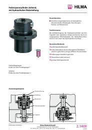
Extending clamp<br />
double-acting, <strong>with</strong> mechanical lock<br />
Applications:<br />
preferably on press beds<br />
<strong>for</strong> <strong>clamping</strong> and locking <strong>dies</strong> and moving bolsters<br />
in presses<br />
Clamping:<br />
For <strong>clamping</strong>, the cylinder piston pushes the <strong>clamping</strong><br />
lever into the <strong>clamping</strong> position. Released by the<br />
hydraulic sequence control, pressure is then applied<br />
to the <strong>clamping</strong> and locking mechanism.<br />
Once the <strong>clamping</strong> <strong>for</strong>ce is built up, the <strong>clamping</strong><br />
element is self-locking. This mechanical lock prevents<br />
unintentional un<strong>clamping</strong> of the die even if there is<br />
a loss of pressure.<br />
Special features:<br />
compact housing and high power density<br />
high functional reliability ensured by position<br />
monitoring and automatic cycle<br />
self-locking by mechanical lock<br />
low operating pressure of 100 bar<br />
easy installation<br />
Un<strong>clamping</strong>:<br />
For un<strong>clamping</strong>, the <strong>clamping</strong> and locking<br />
mechanism is hydraulically unlocked.<br />
Released by the hydraulic sequence control, pressure<br />
is applied to the cylinder piston which pushes the<br />
<strong>clamping</strong> lever into the un<strong>clamping</strong> position.<br />
Un<strong>clamping</strong> and <strong>clamping</strong> positions are monitored<br />
by inductive proximity switches.<br />
Subject to technical modification<br />
Hilma-Römheld GmbH<br />
Schützenstraße 74 · D-57271 Hilchenbach<br />
Phone +49 (0) 2733 / 281-0 · Fax +49 (0) 2733 / 281-113 · www.hilma.de<br />
2.2480<br />
03/2006
Extending clamp<br />
double-acting, <strong>with</strong> mechanical lock<br />
67<br />
Oil port G 1/4<br />
Clamping<br />
Clamping position<br />
Un<strong>clamping</strong> position<br />
20 205<br />
97<br />
30<br />
67<br />
181<br />
200<br />
Oil port G 1/4<br />
Un<strong>clamping</strong><br />
29<br />
Clamping <strong>edge</strong> 60 ±0,2<br />
20<br />
3 Distance to the die<br />
8.2480.0107<br />
right<br />
Clamping <strong>for</strong>ce at 100 bar (kN) 200<br />
Perm. retaining power (kN) 250<br />
Working pressure (bar) 100<br />
Oil consumption <strong>clamping</strong> (cm 3 ) 204<br />
Oil consumption unclamp.(cm 3 ) 188<br />
Pump delivery (l/min) 1,6 - 2,5<br />
Operating temperature (°C) 70<br />
Screws DIN 912-8.8 M 24<br />
Required torque (Nm) 660<br />
Weight (kg) 46<br />
Part no. 8.2480.0105<br />
175<br />
133<br />
93<br />
40<br />
26<br />
left<br />
8.2480.0106<br />
Optional extra: *<br />
Harting plug<br />
HAN 6 E<br />
(Choice of<br />
3 installation<br />
positions)<br />
back<br />
8.2480.0108<br />
21,5<br />
* Plugs are not<br />
supplied <strong>with</strong><br />
the clamp<br />
Special designs are available at request.<br />
Hydraulic diagram<br />
• Design and position of plug-in connection<br />
<strong>for</strong> proximity switches<br />
• Proximity switches <strong>for</strong> temperatures of up to 120°C<br />
RV 1<br />
• Cover plate <strong>for</strong> protection in extremely<br />
dirty environments<br />
• Clamping <strong>edge</strong> height larger than 60 mm<br />
RV 2<br />
Un<strong>clamping</strong> B<br />
Clamping A<br />
2.2480<br />
03/2006<br />
Hilma-Römheld GmbH<br />
Schützenstraße 74 · D-57271 Hilchenbach<br />
Phone +49 (0) 2733 / 281-0 · Fax +49 (0) 2733 / 281-113 · www.hilma.de<br />
Subject to technical modification