Sealings for well construction - GWE German Water and Energy GmbH
Sealings for well construction - GWE German Water and Energy GmbH
Sealings for well construction - GWE German Water and Energy GmbH

Create successful ePaper yourself
Turn your PDF publications into a flip-book with our unique Google optimized e-Paper software.
<strong>Sealings</strong> <strong>for</strong> <strong>well</strong> <strong>construction</strong><br />
General<br />
The <strong>construction</strong> of <strong>well</strong>s <strong>for</strong> the purposes of extracting, monitoring<br />
or surveying groundwater reservoirs usually involves<br />
drilling through cohesive sediments which, in their undisturbed<br />
state, represent hydraulic barriers. These sediments separate<br />
groundwater reservoirs of differing quality <strong>and</strong> mineralisation<br />
<strong>and</strong> prevent contaminated waters from influencing deeper<br />
aquifers. There<strong>for</strong>e, in general, if boreholes are completed<br />
as water or monitoring <strong>well</strong>s, all per<strong>for</strong>ated clay beds must<br />
be reconstructed by the installation of suitable sealing products.<br />
As a leading manufacturer <strong>and</strong> supplier of <strong>well</strong> <strong>construction</strong><br />
materials, the <strong>GWE</strong> Group provides a professional range of<br />
highly effective sealing products based on s<strong>well</strong>ing clays <strong>and</strong><br />
ready-made clay-cement mixtures.<br />
Sealing clays vary in shape, s<strong>well</strong>ing capacity, structural<br />
stability, inherent density <strong>and</strong> geophysical detectability. The<br />
installation in the borehole is completed by pouring the clay<br />
pellets into the <strong>well</strong>, where they settle down at the hole bottom.<br />
Plumb-line checks indicate that the seal has been placed at<br />
the correct depth. Limits are set by the depth of the borehole<br />
<strong>and</strong> the annular geometry.<br />
Pumpable grouts based on a special clay-sealant cement<br />
recipe can also be used. Stable slurries are produced by mixing<br />
the grout material with water.<br />
Requirements<br />
The core requirements <strong>for</strong> sealants in <strong>well</strong> <strong>construction</strong> are:<br />
• Effective seal in finished <strong>well</strong>, without any leakages between<br />
different layers <strong>and</strong> borehole wall<br />
• Safe <strong>for</strong> potable water<br />
• Secure <strong>and</strong> accurate placement<br />
• Detecable by means of geophysical logging<br />
Clay sealings<br />
High s<strong>well</strong>ing clay products have proven to be particularly<br />
successful in the sealing of <strong>well</strong>s. These products are composed,<br />
to a large extent, of the clay mineral bentonite.<br />
The principal advantage of bentonite clay sealings over less<br />
s<strong>well</strong>ing materials composed of kaolinitic/illitic clays lies in<br />
their ability to exp<strong>and</strong> in volume <strong>and</strong> to create s<strong>well</strong>ing pressure.<br />
This compression pushe the seal firmly to the surfaces<br />
(casing/borehole wall) which prevents any leakage through<br />
its superior sealing properties.<br />
Place of installation – Well annulus<br />
As a result of the annular geometry, the gravitional <strong>for</strong>ce is reduced.<br />
The implementation of filler material (e.g. gravel,<br />
s<strong>and</strong>s) results in less compaction of the underlying clay seals<br />
due to relative low constant vertical loads, which are caused<br />
by friction of the fill material along the borehole wall. This is<br />
all the more the case in small diameter <strong>well</strong>s, with the result<br />
that previously placed clay seals are not subject to any appreciable<br />
compaction.<br />
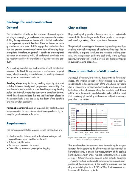
Pressure N/cm2<br />
Annulus pressure distribution ø 150/75 mm<br />
1,00000<br />
0,90000<br />
0,80000<br />
0,70000<br />
0,60000<br />
0,50000<br />
0,40000<br />
0,30000<br />
0,20000<br />
0,10000<br />
0,00000<br />
0,00 20,00 40,00 60,00 80,00 100,00 120,00<br />
Depth m<br />
Diagram 1: Load distribution in a gravel-filled <strong>well</strong> annulus.<br />
Ø hole 150 mm / Ø casing NORIP DN 65<br />
Vertical<br />
load pressure<br />
Lateral<br />
load pressure<br />
This must be taken into account when determining the test parameters<br />
<strong>for</strong> investigating the effectiveness of clay materials in<br />
borehole sealing. To ensure that measurements of the sealing<br />
behaviours are taken under realistic conditions, vertical loads<br />
of max. 1 N/cm 2 should be applied in the test cells (Diagram<br />
1). Greater vertical loads would induce an inadmissable compaction<br />
of the sample; only if the s<strong>well</strong>ing pressure from the<br />
clay sample is higher than 1 N/cm 2 (Test 1 with constant volume)<br />
would this be acceptable.