3.3. Filling Thermofluid - HUBER
3.3. Filling Thermofluid - HUBER
3.3. Filling Thermofluid - HUBER

Create successful ePaper yourself
Turn your PDF publications into a flip-book with our unique Google optimized e-Paper software.
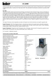
Version 2.1/05<br />
The World of<br />
Thermoregulation<br />
Ministat 125, 230, 240 - efficient thermal regulation<br />
Operating Instructions<br />
ministat 125<br />
ministat 230<br />
ministat 240<br />
Peter Huber Kältemaschinenbau GmbH<br />
Werner-von-Siemens-Strasse 1 · D-77656 Offenburg / Germany<br />
Tel. +49-781-96030 · Fax +49-781-57211<br />
E-Mail: info@huber-online.com · Internet: www.huber-online.com
Peter Huber<br />
Kältemaschinenbau<br />
GmbH<br />
Model<br />
Identification<br />
EC<br />
Directives<br />
Harmonized<br />
Standards<br />
National<br />
Standards<br />
and<br />
Technical<br />
Specifications<br />
Manufacturer:<br />
EC Declaration of Conformity<br />
We declare that the design and model of the thermostat described in the<br />
following and the version put into circulation by complies with all the<br />
relevant and applicable safety and health requirements laid down in the<br />
corresponding EC directive.<br />
If the thermostat is modified without the modification being agreed upon<br />
by the manufacturer, this declaration will become void.<br />
Comp. Control Thermostat Ministat 125 Order no. 740.000X<br />
Comp. Control Thermostat Ministat 230 Order no. 741.000X<br />
Comp. Control Thermostat Ministat 240 Order no. 742.000X<br />
Series 03/04<br />
EC Low Voltage Directive 73/23/EEC<br />
93/68/EEC amendment<br />
EC Electromagnetic Compatibility Directive 89/336/EEC<br />
92/31/EEC, 93/68/EEC,98/13/EEC amendment<br />
EN 61010-1<br />
EN 61010-2-010<br />
EN 61326<br />
DIN 12876-1<br />
DIN 12876-2<br />
DIN 12876-3<br />
Peter Huber Kältemaschinenbau GmbH<br />
Werner-von-Siemens-Straße 1, D-77656 Offenburg<br />
01.11.2003, CEO Daniel Huber
Symbols<br />
Safety<br />
Warning! A potentially hazardous situation. Identifies hazards sufficient<br />
to cause death or severe injuries if the safety instructions are<br />
disregarded.<br />
Caution! A potentially hazardous situation. Identifies hazards sufficient<br />
to cause light injuries if the safety instructions are disregarded.<br />
Definitions from our Huber Glossary and fundamental technical<br />
knowledge.<br />
Stepwise instructions for operating the device and the controller.<br />
Entries at the Polystat cc controller.<br />
Device messages.<br />
Practice.<br />
Service<br />
This is where you get help: the Huber Hotline.<br />
EXTRA<br />
Additional information.
Preface<br />
Dear Customer,<br />
Congratulations! Units and devices manufactured by Peter Huber<br />
Kältemaschinenbau GmbH are always a good choice. Thank you very<br />
much for your trust.<br />
To meet your demands as a user, we have revolutionized the user<br />
interface of our thermostats and implemented a uniform method of<br />
operating almost the entire <strong>HUBER</strong> product range. Many devices,<br />
ranging from small immersion thermostats to large Unichillers are<br />
operated via a single controller generation: Polystat Control.<br />
The controller for Ministats 125, 230 and 240 Ministat Control was<br />
created in the course of this further development. It offers all the<br />
functions and convenience of the Polystat Control and can be<br />
operated just as easily, which brings us back to the concept of<br />
uniform operation.<br />
On the type label on the rear of your device you will find important<br />
information such as:<br />
ministat 240 -40°... +200°C SNr.: 55655/03<br />
[Device name] [Temp.range] [Serial number]<br />
Free choice in operation:<br />
All the Ministats can be operated with three different controller<br />
versions:<br />
Ministat Control cc1, the simple one<br />
Ministat Control cc2, the convenient one<br />
Ministat Control cc3, the one with dialog capabilities<br />
You controller version is identified by the label above the display.<br />
For details on your type of controller, please refer to Chapter 2.2<br />
Please consider only those instructions in the present documentation<br />
that apply to your device type and controller version.<br />
0-3
Content<br />
Preface<br />
1. Safety<br />
1.1. Intended Use, 11-1-2<br />
General Safety Instruction.<br />
2. Device Description<br />
2.1. Structure 21-1<br />
2.2. Controller 22-1<br />
3. Commissioning<br />
3.1. Principles, Media, Safety Instructions 31-1-4<br />
3.2. Preparing the Thermostat for Use. 32-1<br />
<strong>3.3.</strong> <strong>Filling</strong> <strong>Thermofluid</strong> 33-1-2<br />
3.4. Major Presettings 34-1<br />
4. Thermoregulation via Controller<br />
4.1. Safety Instructions and Principles 41-1-2<br />
4.2. Main Menu 42-1<br />
4.3. Start Circulation - Limiting Setpoint - Start / Stop<br />
the Thermoregulation 43-1-4<br />
4.4. Editing Default Settings 44-1-2<br />
4.5. Convenient Thermoregulation-Programs 45-1-6<br />
4.6. Calibration 46-1-2<br />
4.7. Editing Further Settings 47-1-8<br />
5. Shut Down<br />
5.1. Safety Instructions and Principles 51-1<br />
5.2. Draning, Deactivating and Dismantling 52-1<br />
5.3. Maintenance and Service 53-1-2<br />
6. Appendix<br />
6.1. Presettings 61-1<br />
6.2. Interface specification, Data 62-1<br />
6.3. ComBox According to the Namur Standard 63-1-6<br />
6.4. Device Messages 64-1-4<br />
Huber Glossary L-1-8<br />
Technical Data Sheet<br />
List of Spare Parts
1. Safety<br />
1.1. Intended Use<br />
General Safety Instructions<br />
The thermostat is designed for industrial applications.<br />
The thermostat is used for direct and indirect thermoregulation, i.e. for<br />
heating or cooling external substances through suitable thermal fluids.<br />
It must be operated strictly in compliance with the operating<br />
instructions.<br />
The thermostat must not be modified by the plant operator or any<br />
operating personnel.<br />
The thermostat must not be used for purposes other than<br />
thermoregulation in compliance with the operating<br />
instructions.Unintended use or use not in compliance with the operating<br />
instructions may lead to severe personal injury or property damage.<br />
Your device has been designed and constructed according to the state of<br />
the art and in compliance with the generally accepted safety rules.<br />
Nonetheless, your device may constitute an imminent or unexpected<br />
hazard. For this reason, your device has been equipped with safety<br />
devices. Deactivating these safety devices bears high risks and<br />
invalidates the warranty.<br />
Use the device only if it is in good order and condition.<br />
Shut down the device immediately in the case of malfunctions or<br />
failures.<br />
Only qualified personnel is permitted to perform repairs.<br />
Do not bypass, bridge, dismount or deactivate any safety devices.<br />
The manufacturer assumes no liability for damage due to technical<br />
modifications, improper handling or use of the device disregarding the<br />
operating instructions.<br />
The manufacturer assumes no liability for damage due to technical<br />
modifications, improper handling or use of the device disregarding the<br />
operating instructions.<br />
Warning! Risk of injuries!<br />
While operating at high temperatures, the bath lid and the housing could<br />
become very hot.<br />
Only touch the housing and the lid by the grips otherwise there is a risk<br />
of burns!<br />
Never lift the bath’s lid during operation at high temperature:<br />
- Risk of scald /burn through thermal fluid overflow.<br />
Depending on the type of thermal fluid used:<br />
- Risk of caustic vapours causing injuries to the respiratory tract and/or<br />
skin!<br />
(For further information about the chosen thermal fluid please read the<br />
material safety data sheet delivered with it.)<br />
This warning is only applicable for units with this warning sign.<br />
Important: transport damage!<br />
When unpacking the device, inspect it for transport damage.<br />
Please revert to the haulage contractor or shipping agent for settlement<br />
of claims.<br />
Commission a damaged device only after the damage has been repaired<br />
or you have ascertained the full effects of damage and the insurance<br />
agent/haulage contractor/shipping agent has given their permission.<br />
11-1
1. Safety<br />
1.2. Intended Use<br />
General Safety Instructions<br />
Duties of the Plant Operator:<br />
� The operating instructions must be kept readily available in the<br />
immediate vicinity of the thermostat.<br />
� Only sufficiently qualified operating personnel are permitted to use<br />
the thermostat.<br />
� The operating personnel must be trained in handling and using the<br />
thermostat.<br />
� Verify that operating personnel have read and understood the<br />
operating instructions.<br />
� Precisely define the fields of responsibility of the operating<br />
personnel.<br />
� Provide protective clothing for the operating personnel.<br />
Requirements to be Met by the Operating Personnel<br />
� Only personnel assigned and trained by the plant operator may handle<br />
and operate the thermostat.<br />
� The minimum age for operating personnel is 16 years. Within the<br />
workspace, the device operator is responsible for third parties.<br />
� The device operator must be sufficiently qualified<br />
Duties of the Operatorating Personnel:<br />
� The operating personnel must read the operating instructions thoroughly<br />
before handling or using the thermostat.<br />
� The operating personnel must heed all the safety instructions.<br />
� The operating personnel must wear protective clothing when<br />
handling or using the thermostat.<br />
Workspace<br />
The workspace is defined to be at the control panel in front of the thermostat.<br />
The workspace is further defined by the peripheral equipment connected by<br />
the customer. The customer is responsible for taking suitable safety<br />
measures.<br />
Safety Devices<br />
� Over-temperature protection device<br />
� Low liquid level protection<br />
� Mains failure automatic<br />
� Alarm functions<br />
Emergency Plan – Switch off the Power Supply!<br />
Hazardous emission of fluid/vapor from the thermostat or connected pipes/<br />
hoses (very hot, very cold, hazardous chemical compositions) and or fire/<br />
explosion/implosion:<br />
� Strictly heed the safety instructions of the plant operator relating to the<br />
risk of injury and danger to life as well as to the limitation of damage.<br />
� Observe the instructions included in the safety data sheet of the<br />
respective thermal fluid!<br />
11-2
2<br />
Device Description
1<br />
2<br />
3<br />
6<br />
7*<br />
8*<br />
9*<br />
10*<br />
11<br />
12<br />
13<br />
14<br />
Detachable, exchangeable<br />
Ministat Control<br />
Bath lid<br />
Draining connection<br />
Return<br />
RS232/485 SERIAL<br />
ECS STANDBY<br />
(External control signal)<br />
AIF (Analog Interface) REG+E-PROG<br />
POKO ALARM<br />
(Potenzialfreier Kontakt)<br />
Flow<br />
Power supply connection<br />
Handle<br />
Attachment screw<br />
(for the Ministat Control)<br />
2. Device Description<br />
2.1. Structure<br />
NAMUR<br />
designation<br />
*Only available with an optionally<br />
fitted ComBox or a CC3-Controller<br />
Compatible Control Thermostat ministat 125<br />
Compatible Control Thermostat ministat 230<br />
Compatible Control Thermostat ministat 240<br />
Working temperature range of the ministat 125: -25...150°C.<br />
Working temperature range of the ministat 230: -33...200°C.<br />
Working temperature range of the ministat 240: -40...200°C.<br />
View of<br />
RH front<br />
side<br />
View of<br />
rear side<br />
10<br />
11<br />
2<br />
1<br />
21-1<br />
9<br />
8<br />
ministat 125<br />
ministat 125<br />
7<br />
6<br />
14<br />
12<br />
6<br />
13<br />
Please note:<br />
The return/flow of the<br />
ministate 230 and 240 are<br />
in opposite position<br />
(compared to the ministat<br />
125)<br />
The flow direction of the<br />
thermofluid is emborssed on<br />
the casing.<br />
3<br />
ministat 230, 240<br />
11
Display,<br />
control<br />
panel<br />
Connections<br />
Activity<br />
indicator<br />
LEDs<br />
R1<br />
R2<br />
R3<br />
R4<br />
2. Device Description<br />
2.2. Controller<br />
Digital status display<br />
Prompt for a temperature<br />
set-point, input confirmation<br />
(data transfer)<br />
Call of the user menu for<br />
convenient handling<br />
On/Off key to start/stop<br />
thermoregulation<br />
R5 Activity indicator LEDs<br />
R6 over-temperature protection<br />
device<br />
R7 Encoder/ rotate:<br />
Entry of Program numbers,<br />
step numbers, parameters<br />
(e.g. temperature set-point)<br />
Encoder/ press:<br />
Input confirmation<br />
(data transfer)<br />
R8 Pt100 sensor socket<br />
R9 RS 232/485 interface<br />
R10 Power switch<br />
R51Process<br />
temperature control active<br />
(green LED), only with cc2 and cc3:<br />
Temperature is measured by a process<br />
sensor located at the point of control , e.g.<br />
in a reactor.<br />
R52 Heating active (yellow LED)<br />
Ministat Control cc1<br />
Ministat Control cc2<br />
Ministat Control cc3<br />
R10<br />
R10<br />
R9<br />
R10<br />
R53Cooling<br />
/compressor active (blue LED)<br />
R54Pump<br />
active (greene LED):<br />
Thermal fluid is beeing pumped through the<br />
connected application, e.g. around the<br />
reactor jacket.<br />
22-1<br />
R2<br />
R1<br />
R1<br />
R1<br />
R2<br />
R3<br />
R2<br />
R3<br />
R4<br />
R51<br />
R52<br />
R53<br />
R54<br />
R5<br />
R7<br />
R6<br />
R5<br />
R8<br />
R7<br />
R6<br />
R5<br />
R8<br />
R7<br />
R6
3<br />
Commissioning
Preparatory<br />
Measures<br />
for Commissioning<br />
Positioning<br />
Location<br />
3. Commissioning<br />
3.1. Safety Instructions and Principles<br />
Plan the thermoregulation target and procedure.<br />
Determine the device configuration and system structure.<br />
Select an appropriate thermal fluid.<br />
Selection criteria for thermal fluids: Temperature range of the<br />
thermostat, application restrictions building safety regulations, your<br />
projected working temperature, viscosity, flash point.Position the<br />
thermostat and external devices on a stable and even surface. Ensure<br />
that the surface can safely hold the weight of the thermostat and<br />
Caution! Potential risk of injury and material damage:<br />
Keep the device upright during transport.<br />
Place the device in an upright and stable position and make sure that it<br />
cannot tilt over.<br />
Keep the vicinity of the device clean: Prevent slip and tilting hazards.<br />
Lock the wheels of floor-mounted devices once you have positioned<br />
them as desired!<br />
Useful note: Place appropriately large collecting trays under the thermostat and<br />
the application.<br />
The operation on the unit is only allowed in a normal surrounding<br />
according to DIN EN 61010-1:2001:<br />
- Only indoor use.<br />
- To be used in a hight up to 2000m.<br />
- Place the device on a firm, level, non flammable and non-slip<br />
surface.<br />
- Place the device at a distance to walls and the ceiling that permits<br />
sufficient air circulation (heat dissipation, supply of fresh air for the<br />
thermostat and the workspace). A water-cooled unit requires a<br />
minimum distance of10 cm and an air-cooled unit needs a<br />
minimum of 20 cm.<br />
- Ambient temperature min. 5°C to max. 32 °C.<br />
- Maximum relative humidity 80% for temperatures to 32°C.<br />
- Keep power and waterlines as short as possible.<br />
- The device should not be placed such that the access to the<br />
isolator is obstructed.<br />
- Line voltage changes should not exceed +10% of the mains<br />
voltage.<br />
- Transient overvoltages, as they typically occur in the supply<br />
network.<br />
- applicable degree of pollution: 2.<br />
- Overvoltage class II.<br />
- Safety class system: IP20<br />
The workspace of the thermostat must comply with local workplace safety regulations<br />
(ArbStättV 20. März 1975 zuletzt geändert BGBl. I 1996)<br />
Please Note:<br />
All the safety instructions are vital and must be considered during<br />
the operation of the unit in compliance with the operating instructions.<br />
31-1
DIN<br />
12876<br />
3. Commissioning<br />
3.1. Principles, Media and<br />
Safety Instructions<br />
The operating instructions include additional safety instructions. These are<br />
identified through a triangle with an exclamation mark. Thoroughly read and<br />
heed the instructions Non-observance may involve considerable consequences<br />
such as device damage, physical damage or personal injury with fatal<br />
consequences.<br />
Workspace<br />
The workspace is defined to be at the control panel in front of the thermostat.<br />
The workspace is further defined by the peripheral equipment connected<br />
by the customer. The customer is responsible for taking suitable safety<br />
measures.<br />
Safety Devices<br />
^ Overtemperature protection<br />
^ Low liquid level protection<br />
^ Mains failure automatic<br />
^ Alarm functions<br />
Hazardous emission of fluid/vapor from the thermostat or connected pipes/<br />
hoses (very hot, very cold, hazardous chemical compositions) and or fire/<br />
explosion/implosion:<br />
Strictly heed the safety instructions of the plant operator relating to the risk<br />
of injury and danger to life as well as to the limitation of damage.<br />
Observe the instructions included in the safety data sheet of the respective<br />
thermofluid!<br />
Classification according to DIN12876:<br />
Classification Thermoregulation Technical Specifications Identification d<br />
fluid<br />
I non-combustible a Overheating protection c NFL<br />
II combustible b Adjustable overheating protection FL<br />
III combustible b<br />
Please Note: All the safety instructions are vital and must thus be<br />
considered on the job in compliance with the present operating<br />
instructions..<br />
31-2<br />
Adjustable overheating protection FL<br />
Additional low-level protection<br />
a Generally water, other fluids only if they are not combustible in the<br />
temperature range of an individual fault.<br />
b The thermoregulation fluids must have a combustion point of > 65 °C,<br />
i.e. when using ethyl alcohol, only supervised operation is possible.<br />
c The overheating protection can be achieved e.g. through an appropriate fill<br />
level sensor or appropriate temperature control devices.<br />
d Optional according to the selection of the manufacturer<br />
Your thermostat is classified as FL / III
Thermal<br />
fluid<br />
Hazards<br />
during<br />
thermoregulation<br />
3. Commissioning<br />
3.1. Principles, Media and<br />
Safety Instructions<br />
Not suitable for use as a medical device (e.g. in vitro<br />
diagnostic procedures).<br />
Requirements for thermofluids classified as FL:<br />
EN 61010-1: Max. permissible working temperature<br />
25 °C below the flash point!<br />
Maximum viscosity at the lowest working temperature: 50 mm2 /s!<br />
Maximum density of the thermofluid: 1 kg/dm³.<br />
Possible thermoregulation range within the range of the plannedminimum<br />
and maximum working temperature.<br />
Do not use thermofluids with any of the additives ether, ester, strong<br />
mineral acids, oxidizing acids or amines. Do not use demineralized water,<br />
mineral water, sea water or CaCl brines2 Compatibility with the materials used for the thermostat (stainless steel<br />
1.4301 (V2A) and with all the materials used in the system connected to<br />
the thermostat.<br />
For a selection of thermofluids including technical data, please refer to the topical<br />
Huber catalog.<br />
Caution! Potential risk of injury and material damage during<br />
thermoregulation:<br />
In the course of operation of the thermostat, extreme changes in<br />
temperature and pressure and the specific characteristics of the<br />
thermal fluids used may constitute hazards.<br />
Please Note:<br />
All the safety instructions are vital and must be considered on the job in<br />
compliance with the present operating instructions.<br />
31-3
Hazards<br />
through<br />
emission<br />
of fluids<br />
Hazards<br />
through<br />
emission<br />
of gases<br />
Current<br />
connection 2.2<br />
3. Commissioning<br />
3.1. Safety Instructions and Principles<br />
Caution! Potential risk of injury and material damage:<br />
The floor will be slippery when fluids have been spilt!<br />
Thermal fluids with a low flash point constitute a fire hazard!<br />
Hazard of scalding/burning when touching exposed or defective<br />
connections that are hot.<br />
Prevent overflow of the bath.<br />
Prevent leaking fluid-conveying pipes/tubes and connections.<br />
Always remove any liquids spilt on the floor immediately.<br />
Always clean contaminated devices immediately.<br />
Place an appropriately large collecting tray under your external<br />
application.<br />
Caution! Potential risk of injury and material damage:<br />
Risk of causticization of your respiratory tracts and skin through vapors!<br />
Prevent leaks on closed external devices.<br />
Ensure good aeration and ventilation in the vicinity of the thermostat.<br />
Choose thermal fluids for thermoregulation that are not detrimental to<br />
health.<br />
2.1Check<br />
the fuse, power and voltage ratings according to the data sheet<br />
(attached) and the type plate (on the rear side of the device)<br />
Connect the power plug<br />
to the power outlet.<br />
* Figure applies in the<br />
country of manufacture<br />
(Germany) only.<br />
Please Note:<br />
All the safety instructions are vital and must be considered on the job in<br />
compliance with the present operating instructions.<br />
31-4<br />
Shock-proof plug*<br />
for single-phase alternating<br />
current.<br />
2.2
Preparation<br />
Thermoregulation<br />
3. Commissioning<br />
3.2. Preparing the thermostat for use<br />
If you wish to thermoregulate in a bath , please take the following<br />
into consideration:<br />
Seal the pump manifolds with blind plugs and cap nuts (M16x1 /<br />
SW19). While doing so, counter using SW17 at the pump manifold.<br />
If you wish to thermoregulate an externall application, please take the<br />
following into consideration:<br />
Remove the blind plugs and cap nuts at the pump manifolds.<br />
Replace them with suitable hose connections to your external<br />
application.<br />
Alternative<br />
Hazard!<br />
If hoses have to be connected<br />
via shut-off valves:<br />
Only close when performing work<br />
on the reactor, otherwise allways<br />
keep open!<br />
Remember that thermal fluid<br />
expands and contracts with<br />
changes in temperature. Sealing<br />
the external application will<br />
expose the application to these<br />
forces!<br />
ministat 240<br />
Please consider that the return/flow of<br />
the ministat 125 are in opposite position!<br />
For more information, please refer to Chapter 4 „Thermoregulation<br />
via Controller“.<br />
Verify the following:<br />
Make sure that all connections are correct and that there are no leaks!<br />
32-1
Require<br />
ments<br />
Setting<br />
the overtemperature<br />
protection<br />
2<br />
3. Commissioning<br />
<strong>3.3.</strong> <strong>Filling</strong> <strong>Thermofluid</strong><br />
Overtemperature protection<br />
Prepare the thermostat for<br />
thermoregulation and take safety<br />
measures as described below.<br />
Setting the overtemperature<br />
protection device.<br />
Requirements:<br />
A suitable thermal fluid has been<br />
selected for the process<br />
requirements.<br />
The flash point of the thermal fluid is<br />
known.<br />
Procedure:<br />
The over-temperature protection is set<br />
to at least 25 °C below the flash point<br />
of the thermofluid.<br />
For the ministats 125, 230, 240 the<br />
overtemperature protection is set<br />
electronically.<br />
It is independent of the controller.<br />
Use a suitable tool (screw driver or<br />
the like) to press the button in the<br />
center of the over-temperature<br />
protection device. The<br />
overtemperature menu will be<br />
displayed.<br />
For detailed information on the range of accessories incl. technical data and price<br />
quotations, please refer to the Huber catalog or contact your Huber agent.<br />
33-1<br />
Working temperature range of<br />
thermostat (max.)<br />
Flash point of the thermal<br />
fluid<br />
Over-temperature protection<br />
(Overheat)<br />
Permissible temperature<br />
range for set-point entry<br />
Viscosity limit of the<br />
thermal fluid<br />
Working temperature range of<br />
thermostat (min.)<br />
Caution!<br />
The overtemperature protection is an especially important safety<br />
device of your thermostat. It should always be operable and be<br />
tested periodically!<br />
(Refer to 41-1)<br />
OVERTEMP. PROTECTION<br />
-> Overtemp. Setp. heat.<br />
Overtemp. Diplay<br />
Exit<br />
Overtemperature Setpoint Heating: overtemperature value<br />
(adjustable on the Ministat Control 22-1).<br />
Overtemperature Display: the actuell overtemperature value<br />
is displayed.<br />
Temperature rise
<strong>Filling</strong> the<br />
bath<br />
3. Commissioning<br />
<strong>3.3.</strong> <strong>Filling</strong> with <strong>Thermofluid</strong><br />
Bath thermostats<br />
L2 Lift the bath cover<br />
Fill in thermofluid.<br />
Please note the optimum fill<br />
level:<br />
The evaporator coil must be<br />
fully covered with thermal<br />
fluid.<br />
Close the bath cover<br />
Please note that the medium<br />
needs to cool to room<br />
temperature before you replenish<br />
thermofluid!<br />
Caution! Potential risk of injury and material damage!<br />
In the case of high temperatures, the bath cover and housing cover<br />
become very hot.<br />
Please touch the device and the cover at the grips only. Scalding hazard!<br />
Never, under any circumstances, lift the cover of the bath during<br />
operation at high temperatures:<br />
Scalding / burning hazard due to overflow of the thermofluid.<br />
Risk of causticization of your respiratory tracts and skin through vapors!<br />
Important!<br />
For information on thermofluids, refer to 3.1! For a selection of thermofluids<br />
includingtechnical data, please refer to the Huber catalog.<br />
33-2<br />
L2
Language<br />
Deutsch<br />
Set-point<br />
Minimum<br />
set-point<br />
Maximum<br />
set-point<br />
3. Commissioning<br />
3.4. Major Presettings<br />
� When delivered the controller displays will be in German.<br />
Other options can be selected in the „Language“ menu (refer to 4.3.2):<br />
English, Francais<br />
� The thermostat controls the temperature to the predefined<br />
setpoint.<br />
Use the SET key and the encoder to select an other setpoint.<br />
The setting can be changed in the „Alarm Config.“ menu (refer to<br />
4.4.1):<br />
Any temperature value within the performance parameters of the<br />
thermostat (refer to the Data Sheet, Appendix or type plate.) and<br />
the safety limits (refer to 3.1!).<br />
Notes to the temperature limits:<br />
- Select limits no greater than necessary<br />
- Consider the properties of the thermal fluid (flash point and<br />
viscosity)<br />
- Consider the manufacturers recommendations of your application.<br />
The programs for operating the thermostat are described in Chapter<br />
4 of the Operating Instructions.<br />
34-1
4<br />
Thermoregulation via controllers
Checks to<br />
be Performed:<br />
Test Arrangement<br />
Safety<br />
Measures<br />
4. Thermoregulation via<br />
controller<br />
4.1. Safety Instructions and Principles<br />
Compare the device configuration, the system structure and the<br />
selected thermofluid to the thermoregulation target.<br />
Verify the stability of the thermostat and external devices.<br />
Make sure there are no leaking connections.<br />
Make sure the shut-off valves for thermofluid and cooling water (if<br />
applicable) have been opened.<br />
Check the connection to the power supply.<br />
Caution! Potential risk of injury and material damage:<br />
Slip hazard! The floor and the workspace may be slippery when fluids<br />
have been spilt!<br />
Tilt hazard! Make sure the thermostat and external devices are in a<br />
stable position.<br />
Shock hazard! Make sure the connection to the power supply is<br />
undamaged and in perfect working order.<br />
Scalding and burning hazard! Always be aware of extreme<br />
temperatures.<br />
Causticization hazard! Risk of causticization of your eyes, your skin and<br />
your respiratory tracts through hazardous vapors (depends on the<br />
thermofluid used).<br />
Setting the overtemperature protection:<br />
(Applies to Polystats and Compatible Control Thermostats):<br />
When: Immediately after filling the system with thermofluid!<br />
Recommendation:<br />
Periodically test the function of the overtemperature protection by<br />
entering a higher setpoint, e.g. as follows:<br />
Set the overtemperature protection to 30 °C.<br />
Enter the maximum setpoint of 40 °C (since the overtemperature protection is<br />
independent of the controller, you can enter this excessive value without<br />
problems).<br />
Enter the new setpoint of 33 °C (former setpoint 20 °C); the heating will heat to<br />
33 °C, then the thermoregulation process will be stopped automatically with the<br />
error message: „Temp“<br />
The error message will be displayed until the error has been remedied.<br />
Remedy the error. Set the overtemperature protection to a temperature above<br />
40 °C.Switch the thermostat off and then on again.<br />
Entering the minimum and maximum setpoints:<br />
In combination with the working temperature range limits, the<br />
minimum and maximum setpoints provide additional safety for the<br />
thermoregulation process. This means, accidental entry of a<br />
setpoint that is too low or too high will be rejected.<br />
Low liquid level protection:<br />
Monitor the liquid level during operation.<br />
Applies to bath thermostats (Polystats and Compatible Control<br />
Thermostats):<br />
Fill level to approx. 60 – 80 % of the bath height;<br />
for chillers: fill level to approx. 60 – 80 % on the level indicator.<br />
<strong>Thermofluid</strong> level too low: Risk of the thermostat pump running dry.<br />
The controller will report an error and stop the thermoregulation<br />
process.<br />
<strong>Thermofluid</strong> level too high: Overflow, soiling, slip and causticization<br />
hazard!<br />
Change of fluid:<br />
Rinsing fluid and thermofluids come into contact with stainless steel<br />
(V2A), Viton and Perbunan and must be compatible with these<br />
materials.<br />
Room ventilation:<br />
Sufficient aeration and venting in the vicinity of the thermostat<br />
minimizes the risk of overheating and the accumulation of harmful gases<br />
and vapors.<br />
Please Note:<br />
All the safety instructions are vital and must thus be considered<br />
on the job in compliance with the present operating instructions.<br />
41-1
Salutation<br />
Flash<br />
displays<br />
on the<br />
controller<br />
Operating<br />
the<br />
controller<br />
Messages<br />
On/Off<br />
4. Thermoregulation via<br />
Controller<br />
4.1. Safety Instructions and Principles<br />
Manufacturer<br />
Salutation<br />
System<br />
test<br />
Select the<br />
Main Menu<br />
Principles of displays and entries<br />
Electronics test<br />
Memory Test<br />
Pump Test<br />
Name of thermostat, Name of thermostat,<br />
software version working temperature<br />
range<br />
Status<br />
display<br />
Internal 17.5 C<br />
Process n.a.<br />
Internal 17.5 C<br />
Process n.a.<br />
Setpoint 20.0 C<br />
The status display depends on the preset display mode (refer to 61-2).<br />
or or<br />
Select a<br />
menu<br />
option<br />
Ministat 230<br />
The display will<br />
change upon turning<br />
of the encoder Confirm your<br />
entry1) 1) If you fail to confirm your entry within 4 minutes, your selection will<br />
not be saved. The program returns to the status display.<br />
To exit the menu instantaneously at any point, use the Break function * :<br />
Press the SET and MENU keys simultaneously. Your selection will not be<br />
saved.<br />
During operation, ad-hoc messages may be displayed on the controller.<br />
They provide information on irregularities and hazards in the thermostat.<br />
In the case of imminent danger, the controller will display a message<br />
and stop the thermoregulation process/switch off the thermostat at the<br />
same time.<br />
Note:To learn more about the menu and the individual menu options, please<br />
also read sections 4.2 to 4.9 of the present operating instructions.<br />
*applies to Ministat Control CC2 and CC3 only<br />
**applies to Ministat Control CC3 only<br />
41-2<br />
Ministat 230<br />
Stored<br />
Denied<br />
or<br />
Flash display,<br />
return to the<br />
status display<br />
** Press the On/Off key to start/stop the thermoregulation process<br />
(thermoregulation combined with circulation).<br />
For Ministat Control CC1 and CC2 during status display:<br />
Turning the encoder displays the „Temperierung Ein/Aus“ (Thermoregulation<br />
On/Off) menu<br />
Alternative:<br />
** MasterClear function:Pressing the MENU and TEMP keys<br />
simultaneously stops a thermoregulation program in progress or switches<br />
off the analog interface or switches from the digital interface remote<br />
mode to local mode.
Selection<br />
4. Thermoregulation via<br />
Controller<br />
4.2. Main Menu<br />
Contents<br />
The main menu provides menu options and submenu options including all<br />
the settings and selections required to operate the thermostat. (Refer to<br />
42-1!)<br />
1) This menu option is not available for Ministat Control cc1.<br />
2) This menu option is not available for Ministat Control cc2.<br />
Page<br />
MAIN MENU:<br />
43-1 I-> 2nd Setpoint<br />
47-2<br />
47-2<br />
47-5,6<br />
47-1<br />
47-7<br />
43-1<br />
47-4<br />
43-7<br />
46-1<br />
43-7<br />
47-1<br />
46-2<br />
44-2<br />
45-2_5<br />
45-6<br />
45-1<br />
47-8<br />
47-3<br />
43-2<br />
44-1<br />
44-1<br />
441<br />
43-1<br />
47-8<br />
47-8<br />
441<br />
47-1<br />
Main Menu Submenus<br />
1), 2)<br />
Alarm Clear<br />
Alarm Config.<br />
Analog-Interface<br />
Display<br />
Digit. Interface<br />
Venting<br />
Machine Options<br />
Max. Heat Power<br />
Calibration Prog.<br />
Compressor Auto<br />
Mains Failure Auto<br />
Offset Calibration<br />
1), 2)<br />
1), 2)<br />
PI-Parameters<br />
Edit Program 1)<br />
Program Start/Stop 1)<br />
Start Ramp 1)<br />
Acoustic Alarm<br />
Software version<br />
Setpoint Limits<br />
Language<br />
Temperature Scale<br />
Control Mode<br />
Circulation<br />
Select Usermenu<br />
Config Usermenu<br />
Factory Default<br />
Time Scale<br />
Exit<br />
1), 2)<br />
42-1<br />
I-> ALARM CONFIGURATION:<br />
I-> Alarm Mode<br />
Lower Alarm Limit<br />
Upper Alarm Limit<br />
Level Alarm Delay<br />
Exit<br />
I-> Display<br />
I-> Display modes<br />
optimise display<br />
Options<br />
Exit<br />
I-> Digit. Interface :<br />
I-> Hardware RS<br />
Baud rate<br />
Protocol<br />
slave address<br />
Exit<br />
I-> 2-P.CALIBR.:<br />
I-> Edit TCal1<br />
Edit TCal2<br />
Control to TCal1<br />
Control to TCal2<br />
Exit<br />
I-> OFFSET CALIBRATION:<br />
I-> internal sensor<br />
process sensor<br />
Exit<br />
I-> INITIALISE:<br />
I-> Unit Data<br />
User menus<br />
Programmer<br />
All together<br />
Exit
Circulation<br />
Venting<br />
2. Setpoint<br />
4. Thermoregulation via<br />
Controller<br />
4.3. Utilities<br />
1. Circulation<br />
2. Venting<br />
3. 2. Setpoint (for Ministat Control cc3 only)<br />
All the factory defaults can be customized in the menu.<br />
All the factory defaults can be restored via the „Factory Default“<br />
option (with the thermoregulation function switched off). (Also<br />
refer to „Salutation“ 4.1).<br />
MAIN MENU:<br />
Calibration Prog.<br />
I-> Circulation<br />
Compressor Auto<br />
CIRCULATION:<br />
I-> Off<br />
On<br />
MAIN MENU:<br />
Time Scale<br />
I-> venting<br />
Exit<br />
VENTING:<br />
I-> Off<br />
On<br />
please enter:<br />
Pump ON (s)<br />
10<br />
Please enter:<br />
Pump ON (s)<br />
15<br />
Please enter:<br />
Pump OFF (s)<br />
10<br />
Please enter:<br />
Pump OFF (s)<br />
15<br />
MAIN MENU:<br />
I-> 2. Set-point<br />
Acoustic Alarm<br />
Alarm Clear<br />
please enter:<br />
2. Set-point<br />
15.0 C<br />
Please enter:<br />
2. Set-pointt<br />
25.0 C<br />
„Circulation“ option<br />
„Off“<br />
No pump operation (related to the<br />
thermoregulation process) or stop of the<br />
alternating pump operation.<br />
„On“<br />
Start of the alternating pump operation<br />
(without thermoregulation) e.g. to enhance<br />
the filling procedure.<br />
„Venting“ option:<br />
Can be selected only with thermoregulation<br />
switched off.<br />
Using the venting option, the pump can be<br />
operated in intervals in alternating mode,<br />
e.g. for enhanced venting of external<br />
applications.<br />
„On“<br />
The default settings for the time intervals<br />
for pump operation/pause may have to be<br />
edited (take into consideration the<br />
viscosity of the thermofluid and the<br />
system dimensions) and – at the same<br />
time – start of the alternating pump<br />
operation in intervals.<br />
„Off“ Stop the alternating pump operation<br />
in intervals.<br />
(Refer to 3.4!)<br />
Caution! Potential risk of injury and material damage!<br />
Please take into consideration the capacity and fill level of the<br />
thermostat and the connected systems as well as the viscosity and<br />
expansion characteristics of the thermofluid used.<br />
Please prevent overflow of the fluid. Refer to 3.4!<br />
„2nd Setpoint“ option (exclusively<br />
available for Ministat controllers cc3)<br />
Entry of the 2 nd setpoint. This setpoint is<br />
enabled only if an error occurs in the<br />
analog control. Refer to „Analog Interface“!<br />
When entering the 2 nd setpoint, the same<br />
applies as to the „standard“ setpoint: the<br />
characteristics of the thermofluid, the<br />
thermoregulation objective and the safety<br />
measures must always be taken into<br />
consideration.<br />
43-1
Setpoint<br />
Limit<br />
4. Thermoregulation via<br />
Controller<br />
4.3. Limiting the Thermoregulation<br />
Range<br />
4. Setpoint Limits<br />
All the factory defaults can be customized in the menu.<br />
All the factory defaults can be restored via the „Factory Default“<br />
option (with the thermoregulation function switched off). (Also<br />
refer to „Salutation“ 4.1).<br />
MAIN MENU:<br />
Select Usermenu<br />
I-> Set-point limit<br />
Software Version<br />
Please enter:<br />
Minimum Set-point<br />
5.0 C<br />
Please enter:<br />
Minimum Set-point<br />
10.0 C<br />
Please enter:<br />
Maximum Setpoint<br />
35.0 C<br />
Please enter:<br />
Maximum Set-point<br />
170.0 C<br />
„Setpoint Limits“ option:<br />
Enter the desired minimum setpoint and<br />
confirm your entry (e.g. 10.0 °C).<br />
The minimum setpoint is a safety limit for<br />
thermoregulation. Where:<br />
The lowest permissible temperature<br />
value >= minimum setpoint (3.1, 4.1).<br />
It is not possible to enter a setpoint lower<br />
than the minimum setpoint.<br />
Enter the desired maximum setpoint and<br />
confirm your entry (e.g. 170.0 °C).<br />
The maximum setpoint is a safety limit for<br />
thermoregulation. Where:<br />
The highest permissible temperature<br />
value
Entry of<br />
Setpoint<br />
4. Thermoregulation via<br />
Controller<br />
4.3. Enter a Setpoint - Start<br />
All the factory defaults can be customized in the menu.<br />
All the factory defaults can be restored via the „Factory Default“<br />
option (with the thermoregulation function switched off). (Also<br />
refer to „Salutation“ 4.1).<br />
17.5 C<br />
Please enter:<br />
set-point<br />
50 C<br />
Press the SET key.<br />
The setpoint will be shown on the status<br />
display.<br />
Enter the new setpoint by turning the<br />
encoder (e.g. to 50 °C).<br />
Confirm your entry by pressing the encoder<br />
or the SET key.<br />
Start thermoregulation only after all the prerequisites have been met (refer<br />
to 3 Commissioning), especially:<br />
Suitable location (3.1)<br />
Correct connections (3.2)<br />
Ambient temperature max. 30 °C (3.1)<br />
Correct setting of the overtemperature protection (4.1)<br />
Correct setting of the setpoint limits (4.4)<br />
Ministat cc1 and cc2 controllers:<br />
Start the thermoregulation process by turning the encoder.<br />
Ministat cc3 controller:<br />
The thermoregulation process to the new setpoint is started by pressing<br />
the TEMP key.<br />
To stop the thermoregulation process: Refer to page 43-4!<br />
Permissible temperature range for the setpoint<br />
(can be defined precisely to 1/10th)<br />
Working Viscosity Minimum<br />
Maximum<br />
Temperature<br />
Range of<br />
thermostat<br />
limit setpoint<br />
setpoint<br />
It is not possible to enter a setpoint beyond the setpoint limits.<br />
Caution!<br />
The overheating point and the setpoint must be 25 degrees below<br />
the flash point of the thermofluid and the setpoint must be above<br />
the temperature at which the thermofluid attains a viscosity higher<br />
than 50 mm 2 /s.<br />
(3.1.!)<br />
Note: Gas venting (Prog. 55) and decalcify.<br />
43-3<br />
Overtemperature<br />
protection (overheat)<br />
Flash point of the<br />
thermofluid
Abort<br />
4. Thermoregulation via<br />
Controller<br />
4.3. Terminating the Thermoregulation<br />
Process<br />
Ministat Control cc1/cc2: The thermoregulation process can be<br />
aborted at any time by pressing the power switch. You can also<br />
turn the encoder until the „Thermoregulation“ menu is displayed, in<br />
which you can select „Off“ or „On“.<br />
Ministat Control cc3: The thermoregulation process can be aborted<br />
at any time by pressing the On/Off key on the controller.<br />
Caution!<br />
Do not stop the thermoregulation process by pulling the power plug.<br />
When the controller is switched back on, various device messages<br />
may be displayed and faults may occur.<br />
43-4<br />
When you press the On/<br />
Off key or the power<br />
switch to stop the<br />
thermoregulation process,<br />
all the LEDs will go out.<br />
Actuate the power switch of the thermostat to interrupt the power<br />
supply.
Factory<br />
Default<br />
Language<br />
Temperature<br />
Scale<br />
Control<br />
Mode<br />
4. Thermoregulation via<br />
Controller<br />
4.4. Editing Default Settings<br />
1. Restoring the factory default<br />
2. Selecting a language for the controller display<br />
3. Temperature scale<br />
4. Control mode – internal/ external<br />
All the factory defaults can be customized in the menu.<br />
All the factory defaults can be restored via the „Factory Default“<br />
option (with the thermoregulation function switched off). For this<br />
purpose, proceed as described below. (Also refer to „Salutation“<br />
4.1).<br />
MAIN MENU:<br />
Config User<br />
I->Factory default<br />
INITIALISE:<br />
I-> Unit Data<br />
Programmer<br />
User menus<br />
All together<br />
Exit<br />
INITIALISE:<br />
User menus<br />
I-> All together<br />
Exit<br />
MAIN MENU:<br />
Set-point limits<br />
I-> Language<br />
Temperature Scale<br />
Language:<br />
I-> Deutsch<br />
English<br />
Francais<br />
MAIN MENU:<br />
Language<br />
I-> Temperature Scale<br />
Temperature Scale:<br />
I-> Celsius<br />
Fahrenheit<br />
Kelvin<br />
MAIN MENU:<br />
Temperature Scale:<br />
I-> Control mode<br />
Control mode:<br />
I->Internal<br />
Process (Cascade)<br />
„Factory Default“ option<br />
Submenu selection:<br />
„Unit Data“: Important if you replaced<br />
device components or accessories.<br />
„Programmer“<br />
Deletion of all the thermoregulation<br />
programs<br />
„User menus“<br />
Restores the „User menu“ factory default.<br />
„All together“<br />
Restores all the factory defaults.<br />
Caution! All the thermoregulation programs<br />
incl. ramps entered by the customer will<br />
be deleted!<br />
„Exit“ option:<br />
The factory defaults will not be restored.<br />
For selecting the language that is to be<br />
For selecting the temperature unit for<br />
display<br />
Not available for Ministat Control cc1!<br />
For definitions of internal and external thermoregulation, please<br />
refer to the Huber Glossary, keyword Control Mode – Internal,<br />
Process<br />
44-1
PI-<br />
Parameters<br />
PI-Test<br />
4. Thermoregulation via<br />
Controller<br />
4.4. Editing Default Settings<br />
Test Part 1<br />
P - portion<br />
I - portion<br />
5. PI-Parameters<br />
Factory Default:<br />
The P-parameter (proportional parameter) and the I-parameter<br />
(integral parameter) influence the thermoregulation behavior of your<br />
thermostat. The factory default of the P-parameter is 5,000, that<br />
of the I-parameter is 1,000.<br />
The factory default is well suited for a large number of<br />
applications.<br />
New settings:<br />
The PI-parameters can be edited as desired.<br />
Value range of the P-parameter: 50 ... 30,000<br />
Value range of the I-parameter: 0 ... 30,000<br />
Test your thermoregulation process for optimum settings by entering<br />
new value pairs for the thermoregulation mode (internal or<br />
process<br />
Test Part 2<br />
P - Portion<br />
I - Portion<br />
External thermoregulation Temperature change by 20 °C after<br />
each setting up to U* (ballistic effect)<br />
50 1000 2000 3000 ... 10.000 ...up to Ü*e.g.<br />
12.000<br />
External 0 thermoregulation 0 0 Temperature 0 0 change by 20 °C after<br />
each setting up to O**<br />
12.000 12.000 12.000 12.000<br />
1.000 2.000 5.000 ... up to O** e.g. 15.000<br />
* U: Ballistic effect: At the thermoregulation target, the actual value<br />
oscillates about the setpoint.<br />
**O: Optimum ratio between the accuracy of the controller and your<br />
desired speed.<br />
Rule: Fast thermoregulation due to a high P and a low I-parameter<br />
results in a high ballistic effect.<br />
MAIN MENU:<br />
Offset Calibretion<br />
I-> PI-Parameter<br />
PowerOff AutoStart<br />
Please enter:<br />
P-Intern<br />
2500<br />
Please enter:<br />
P-Internal<br />
50<br />
Please enter:<br />
I-Internal<br />
1000<br />
Please enter:<br />
I-Internal<br />
0<br />
Thermoregulation:<br />
1. Heating by 20 °C with P/I=50/0, then<br />
cooling by 20 °C<br />
2. Heating by 20 °C with P/I=1000/0, then<br />
cooling by 20 °C<br />
3. Continue as described for Test Part 1 (table<br />
above) until all the relevant P-parameters have<br />
been tested.<br />
4. Heating by 20 °C with P/I=12,000/1,000, then<br />
cooling by 20 °C<br />
5. Heating by 20 °C with P/I=12,000/2,000, then<br />
cooling by 20 °C<br />
6. Continue as described for Test Part 1<br />
(table above) until all the relevant Iparameters<br />
have been tested.<br />
44-2
Start<br />
Ramp<br />
4. Thermoregulation via<br />
Controller<br />
4.5. Convenient Thermoregulation –<br />
Programs<br />
1. Start Ramp (for Ministat Control cc2/cc3 only)<br />
All the factory defaults can be customized in the menu.<br />
All the factory defaults can be restored via the „Factory Default“<br />
option (with the thermoregulation function switched off). (Also<br />
refer to „Salutation“ 4.1).<br />
If you want to change the working temperature slowly and<br />
smoothly instead of suddenly, you should implement the setpoint<br />
change via a ramp.<br />
MAIN MENU:<br />
Start/stop Program<br />
I-> Start Ramp<br />
Temperature Scale<br />
Please enter:<br />
Go to temperature<br />
20 C<br />
Please enter:<br />
Go to temperature<br />
70 C<br />
Please enter:<br />
Time (min)<br />
1<br />
Please enter:<br />
Time (min)<br />
90<br />
„Start Ramp“ option:<br />
Enter the desired final temperature of the<br />
ramp (ramp setpoint), e.g. 70 °C.<br />
Enter the time (in minutes) the<br />
thermoregulation to the ramp setpoint<br />
should take, e.g. 90 minutes.<br />
Starting the ramp:<br />
The ramp will automatically be started<br />
once you have confirmed the time<br />
parameter.<br />
Completion of the ramp:<br />
Once the ramp setpoint has been reached<br />
(e.g. after 90 minutes), the thermostat will<br />
keep the new actual temperature<br />
constantly on the new value (e.g. 70 °C<br />
Interrupting the ramp:<br />
The ramp can be interrupted in the course<br />
of the process by entering a new setpoint<br />
(SET/encoder).<br />
Caution!<br />
The setpoint must be 25 degrees below the flash point of the<br />
thermofluid and above the temperature, at which the thermofluid<br />
attains a viscosity higher than 50 mm 2 /s. (3.1.!)<br />
45-1
Edit<br />
Program<br />
4. Thermoregulation via<br />
Controller<br />
4.5. Convenient Thermoregulation –<br />
Programs<br />
2. Edit Program<br />
(Exclusively for Ministat Control cc2/ cc3)<br />
All the factory defaults can be customized in the menu. All the<br />
factory defaults can be restored via the „Factory Default“ option<br />
(with the thermoregulation function switched off). (Also refer to<br />
„Salutation“ 4.1).<br />
Creation of a separate thermoregulation program<br />
Ministat cc2 controller: 1 thermoregulation program for editing (can<br />
always be overwritten) with as many as 5 segments.<br />
Mionistat cc3 controller: 10 thermoregulation programs for<br />
selecting and editing (can always be overwritten). A total of 50<br />
segments are available.<br />
One segment can maximally span a period of 54 hours.<br />
Programming is done in steps according to the „Edit Program“<br />
menu item.<br />
Planning (Example):<br />
A fluid in an external bath is to be heated and cooled in 3 steps.<br />
The heating process is to be temperature-stable and the cooling<br />
process time-stable. For the time it takes to cool the bath, an<br />
agitator is to be controlled via the potential-free contact.<br />
At the end of the program, the thermostat is to maintain the bath<br />
Example:<br />
Programm 0<br />
MAIN MENU:<br />
PI-Parameters<br />
I-> Edit Program<br />
Start Progr.<br />
PROGRAMMER:<br />
I-> Program 0<br />
Program 1<br />
Program 2<br />
Program 3<br />
Program 4<br />
Program 5<br />
Program 6<br />
Program 7<br />
Program 8<br />
Program 9<br />
exit<br />
T (°C)<br />
60<br />
20<br />
-10<br />
Segment 0 Segment 1 Segment 2<br />
„Edit Program“ option<br />
Options in the „Programmer“ (PR)<br />
submenu: 10 Programs<br />
„Program 1“ option<br />
Upon initial commissioning, all the<br />
programs will still be „empty“, i.e. they<br />
have not been assigned any segments. In<br />
the course of the application, these<br />
programs may be completely filled with<br />
segments.<br />
For further programs, you may edit existing<br />
ones.<br />
Caution!<br />
The setpoint must be 25 degrees below the flash point of the<br />
thermofluid and above the temperature at which the thermofluid<br />
attains a viscosity higher than 50 mm 2 /s. (4.1.!)<br />
45-2<br />
30 36 46 t (min)
Edit<br />
Program<br />
4. Thermoregulation via<br />
Controller<br />
4.5. Convenient Thermoregulation –<br />
Programs<br />
FUNCTIONS PR:<br />
Attach Segment<br />
I-> insert Segment<br />
modify Segment<br />
Delete Segment<br />
show Segment<br />
Delete Program<br />
Exit<br />
3. Edit Program (exclusively for Ministat Control cc2/ cc3)<br />
PROGRAM NO.1:<br />
I-> Set point SegEnd<br />
Segment period<br />
Modify Segment<br />
Control mode<br />
Options<br />
Save & exit<br />
Exit<br />
Submenu selection:<br />
„Programmer“ (PR)/ „Program 0“/<br />
„Functions PR“:<br />
„Program 1“ options<br />
„Attach Segment“ (for the 1 st segment, this<br />
corresponds to „Insert Segment“). The<br />
parameters for the 1 st segment are defined in<br />
the following.<br />
(Refer to the example of program 0 on page<br />
45-2!)<br />
Please enter:<br />
Set point SegEnde<br />
0.0 C<br />
„Setpoint SegEnd“ option: entry of the setpoint for the 1 st segment of<br />
the 1 st program, e.g. 60 °C.<br />
PROGRAM NO.1:<br />
Set point SegEnd<br />
I-> Segment period<br />
Modify Segment<br />
Control mode<br />
Options<br />
Save & exit<br />
Exit<br />
PROGRAM NO.1:<br />
Set point SegEnd<br />
Segment period<br />
I-> Control mode<br />
Options<br />
Save & exit<br />
Exit<br />
Please enter:<br />
Segment period (s)<br />
1<br />
TEMPERIERMODUS:<br />
CONTROL MODE:<br />
I-> Intern Internal<br />
Extern Process (cascade)<br />
OPTIONs PR:<br />
Pot.free Contact<br />
Analog Output<br />
End condition<br />
-> Stability<br />
exit<br />
45-3<br />
Please enter:<br />
Set point SegEnde<br />
60.0 C<br />
Please enter:<br />
Segment period (s)<br />
1800<br />
„Segment period“ option: entry of the time period for the 1 st segment of<br />
the 1 st program, e.g. 1800 seconds.<br />
OPTIONs PR:<br />
Pot.free Contact<br />
Analog Output<br />
I-> End condition<br />
Stability<br />
exit<br />
CONTROL MODE:<br />
Internal<br />
I-> Process (cascade)<br />
„Control Mode“ option: example: selection of external thermoregulation.<br />
PROGRAMM NO.1:<br />
Set point SegEnd<br />
Segment period<br />
Modify Segment<br />
Control mode<br />
I-> Options<br />
Save & exit<br />
Exit<br />
AT SEGMENT-END:<br />
stop regulation<br />
I-> continue loop<br />
„Options“ menu option: Selection of the „End condition“ for the 1 st<br />
segment of the 1 st program, e.g. „Continue“, i.e. the temperature<br />
value of the segment end is maintained. („Stop Regulation“ =<br />
thermoregulation to the former setpoint at the end of the segment)<br />
STABILITY:<br />
I-> Time-stable<br />
Temperature-stable<br />
„Stability“ option, e.g. „Time-Stable“ for the 1 st Segment of the<br />
1 st program.<br />
Time-Stable: The segment period entered has priority for the segment end.<br />
Temperature-Stable: The „Setpoint SegEnd“ has priority for the end of the<br />
segment.
Edit<br />
Program<br />
Potential-free<br />
contact<br />
4. Thermoregulation via<br />
Controller<br />
4.5. Convenient Thermoregulation –<br />
Programs<br />
4. Edit Program<br />
(Exclusively for Ministat Control cc2/ cc3)<br />
All the factory defaults can be customized in the menu.<br />
All the factory defaults can be restored via the „Factory Default“<br />
option (with the thermoregulation function switched off). (Also<br />
refer to „Salutation“ 4.1).<br />
Select „Exit“ to return to the superordinate level<br />
PROGRAM NO.1:<br />
Set point SegEnd<br />
Segment period<br />
Control mode<br />
Options<br />
I-> Save & exit<br />
Exit<br />
FUNKTIONS PR:<br />
Delete Segment<br />
I-> show Segment<br />
Delete Program<br />
Exit<br />
OPTIONs PR:<br />
Pot.free Contact<br />
Analog Output<br />
End condition<br />
Stability<br />
I->exit<br />
„Save & Exit“ option: Saving of all the data for<br />
the 1st segment in the 1st program. The 1st program has thus been created.<br />
If you exit the „Program 1“ level without „Save<br />
& Exit“, all the data entered for this segment up<br />
to now that have not yet been saved will be<br />
discarded.<br />
After „Save & Exit“ the program will return to<br />
the superordinate level „Functions PR“.<br />
Prog:0 Seg:0<br />
Temp:60 Contr:Cas<br />
Time:1800 Stab:Time<br />
Poco:0 AnO:0<br />
„Functions PR“ option, „Show segment“ option: this is where you can<br />
check your entries. Press the MENU key to exit the display.<br />
The program will return to „Functions PR“, where you select „Attach<br />
Segment“ as shown in the example. The entries now correspond to those<br />
for segment 1 taking the values from our example. In this segment, you<br />
must additionally select the potential-free contact for controlling the<br />
agitator in segment 2.<br />
FUNKTIONS PR:<br />
I-> Attach Segment<br />
insert Segment<br />
modify Segment<br />
PROGRAM NO.1:<br />
Set point SegEnd<br />
I-> Segment period<br />
Control mode<br />
PROGRAM NO.1:<br />
Set point SegEnd<br />
Segmentdauer<br />
I-> Temperiermodus<br />
PROGRAM NO.1:<br />
Sollwert SegEnde<br />
Segmentdauer<br />
I-> Temperiermodus<br />
Please enter:<br />
Set point SegEnd<br />
60.0<br />
Please enter:<br />
Segment period (s)<br />
1800<br />
TEMPERIERMODUS:<br />
CONTROL MODE:<br />
I-> Intern Internal<br />
Extern Process (Cascade)<br />
OPTIONS PR:<br />
I-> Pot.free contact<br />
Analog output<br />
End condition<br />
OPTIONS PR:<br />
Analog output<br />
I-> End condition<br />
Stability<br />
OPTIONS PR:<br />
End condition<br />
-> Stability<br />
exit<br />
OPTIONS PR:<br />
End condition<br />
Stability<br />
-> exit<br />
45-4<br />
Select „Exit“ to return<br />
to the superordinate<br />
level „Program 1“.<br />
Please enter:<br />
Set point SegEnd<br />
-10.0 C<br />
Please enter:<br />
Segment period (s)<br />
360<br />
TEMPERIERMODUS:<br />
CONTROL MODE:<br />
I-> Internal Intern<br />
I-> Extern Process (Cascade)<br />
POCO ACTIVE:<br />
No<br />
I-> Yes<br />
AT SEGMENT-END:<br />
I-> Stop regulation<br />
Continue loop<br />
Repeat<br />
STABILITY:<br />
time-stable<br />
I-> Temperature-stable<br />
PROGRAMM NO.1:<br />
Options<br />
I-> save segment<br />
exit
Edit<br />
Program<br />
4. Thermoregulation via<br />
Controller<br />
4.5. Convenient Thermoregulation –<br />
Programs<br />
5. Edit Program<br />
(Exclusively for Ministat Control cc2/ cc3)<br />
All the factory defaults can be customized in the menu.<br />
All the factory defaults can be restored via the „Factory Default“<br />
option (with the thermoregulation function switched off). (Also<br />
refer to „Salutation“ 4.1).<br />
Select „Exit“ to return to the superordinate level.<br />
„Functions PR“ option, „Show segment“ option: this is where you can<br />
check your entries. Press the MENU key to exit the display.<br />
The program will return to „Functions PR“, where you select<br />
„Attach Segment“ as shown in the example. The entries now<br />
correspond to those for segment 1 taking the values from our<br />
example. In this segment, you must additionally select the potential-free<br />
contact for controlling the agitator in segment 2.<br />
FUNKTIONS PR:<br />
I-> Attach Segment<br />
Insert Segment<br />
Modify Segment<br />
PROGRAMM NO.1:<br />
Set point SegEnd<br />
I-> Segment<br />
Temperiermodus<br />
PROGRAMM NO.1:<br />
Set point SegEnd<br />
Period Segm.<br />
I-> Control mode<br />
Please enter:<br />
Set point SegEnd<br />
-10.0<br />
Please enter:<br />
Period Segm. (s)<br />
360<br />
TEMPERIERMODUS:<br />
CONTROL MODE:<br />
I-> Intern Internal<br />
Extern Process (Cascade)<br />
OPTIONS PR:<br />
Analog output<br />
I-> End condition<br />
Stability<br />
OPTIONS PR:<br />
End condition<br />
-> Stability<br />
exit<br />
OPTIONS PR:<br />
End condition<br />
Stability<br />
-> Exit<br />
45-5<br />
Please enter:<br />
Set point SegEnd<br />
20.0 C<br />
Please enter:<br />
Period Segm. (s)<br />
600<br />
TEMPERIERMODUS:<br />
CONTROL MODE:<br />
I-> Internal Intern<br />
I->Process Extern (Cascade)<br />
AT SEGMENT-END:<br />
Stop regulation<br />
I-> Continue loop<br />
STABILITY:<br />
Time stable<br />
I-> Temperature stable<br />
PROGRAMM NO.1:<br />
Options<br />
I-> save & exit<br />
Exit<br />
You have now created a thermoregulation program with 3 segments<br />
according to our example.<br />
Caution!<br />
Before activating the program, make sure you are using a suitable<br />
thermofluid!<br />
The setpoint must be 25 °C below the flash point of the thermofluid<br />
and above the temperature at which the thermofluid attains a<br />
viscosity higher than 50 mm 2 /s. (3.1.!)<br />
Please Note:<br />
You cannot create thermoregulation programs with the Ministat<br />
controller cc1.<br />
You can create one thermoregulation program with the Ministat<br />
controller cc2.<br />
You can create 10 thermoregulation programs with the Ministat<br />
controller cc3.
Start/Stop<br />
Program<br />
4. Thermoregulation via<br />
Controller<br />
4.5. Convenient Thermoregulation –<br />
Programs<br />
6. Start Program (Exclusively for Ministat Control cc2/ cc3)<br />
MAIN MENU:<br />
Software Version<br />
I-> Start/Stop Program<br />
Start Ramp<br />
PROGRAMMER:<br />
I-> Program 1<br />
Program 2<br />
Program 3<br />
Program 4<br />
Program 5<br />
Program 6<br />
Program 7<br />
Program 8<br />
Program 9<br />
Program 10<br />
Exit<br />
SERVICE-PROGRAM:<br />
Program Pause<br />
Program Continue<br />
Go To Segment No.<br />
Program stop<br />
Exit<br />
Progr.:1 Segm.:1<br />
Internal 21.2<br />
Process 17.5<br />
Setpoint 17.6<br />
„Internal“:<br />
development of the<br />
internal actual value<br />
„Process“:<br />
development of the<br />
external actual value<br />
„Setpoint“:<br />
Calculated actual<br />
setpoint.<br />
60.0 C<br />
„Start/Stop Program“ option<br />
If no program has been started:<br />
Submenu selection:<br />
„Program 1“ example Ministat cc3:<br />
10 programs / 50 segments<br />
(However one program cannot contain<br />
more than 40 segments)<br />
Ministat Control cc2: 1 program / 5<br />
segments<br />
If a program has already been started:<br />
Submenu selection:<br />
„Program Pause“<br />
„Program Continue“<br />
„Go To Segment No.“<br />
„Program Stop“<br />
„Exit“<br />
Program 1 will be started.<br />
Aborting the thermoregulation program<br />
With Ministat controller cc2: Power switch<br />
or new menu (using„Program Stop“).<br />
With Ministat controller cc3:<br />
Break function (press the MENU and On/<br />
Off keys simultaneously).<br />
Alternative: Power switch or new menu.<br />
Standard end of the thermoregulation<br />
process once the thermoregulation program<br />
has been completely executed,<br />
according to:<br />
- programmed segment end (the<br />
temperature of the last segment setpoint is<br />
maintained (Continue) or thermoregulation<br />
to the last setpoint entered outside the<br />
program) or repeating of Temp. Program.<br />
- Stability: Time-Stable (i.e. after the<br />
programmed segment period has elapsed)<br />
or Temperature-Stable (i.e. after the<br />
segment setpoint has been attained).<br />
Once the program has been completely<br />
executed, the status display will be<br />
shown.<br />
Caution!<br />
Before activating the program, make sure you are using a suitable<br />
thermofluid!<br />
The setpoint must be 25 °C below the flash point of the thermofluid<br />
and above the temperature at which the thermofluid attains a<br />
viscosity higher than 50 mm 2 /s. (4.1.!)<br />
45-6
Calibration<br />
Prog.<br />
4. Thermoregulation via<br />
Controller<br />
4.6. Calibration<br />
1. Calibration Program<br />
All the factory defaults can be customized in the menu.<br />
All the factory defaults can be restored via the „Factory Default“<br />
option (with the thermoregulation function switched off). (Also<br />
refer to „Salutation“ 4.1).<br />
MAIN MENU:<br />
Analog Interface<br />
I-> Calibration prog.<br />
Circulation<br />
2-P.CALIBR. INTERNAL:<br />
I-> Edit T-Cal1/2<br />
Control to T-Cal1<br />
Control to T-Cal2<br />
exit<br />
Please enter:<br />
Set-point TCal1<br />
6 C<br />
Please enter:<br />
Set-point TCal1<br />
10 C<br />
2-P.calibration:<br />
Edit TCal1<br />
I-> Edit TCal2<br />
Control to T-Cal1<br />
Control to T-Cal2<br />
exit<br />
please enter:<br />
set-point TCal2<br />
100 C<br />
Please enter:<br />
set-point TCal2<br />
40 C<br />
2-P.calibration:<br />
Edit TCal1<br />
Edit TCal2<br />
I-> Control to T-Cal1<br />
Control to T-Cal2<br />
exit<br />
2-P.calibration:<br />
Edit TCal1<br />
Edit TCal2<br />
Control to T-Cal1<br />
I-> Control to T-Cal2<br />
Exit<br />
„Calibration Prog.“ option<br />
Is used exclusively to calibrate the internal<br />
sensor.<br />
Use a calibrated reference thermometer as<br />
a second temperature sensor for<br />
calibration.<br />
Submenu selection: „Edit TCal1/2“<br />
Entry of the 1 st of two calibration<br />
temperatures, e.g. change from 6°C to<br />
10 °C.<br />
Entry of the 2 nd of two calibration<br />
temperatures, e.g. change from 100°C to<br />
40 °C.<br />
Submenu selection: „Control to TCal1“<br />
Start thermoregulating until the 1 st<br />
calibration temperature has been reached.<br />
If your reference thermometer indicates the<br />
set temperature reliably, compare the value<br />
to the actual value display of the Ministat<br />
controller. Deviations can be corrected<br />
using the encoder.<br />
Submenu selection: „Control to TCal2“<br />
Proceed as described for TCal1.<br />
Exit the menu once you have completed<br />
the calibration procedure.<br />
The two-point calibration includes all the values between T1 and<br />
T2. With offset calibration, on the other hand, the entire<br />
temperature level is shifted by one value on a linear level.<br />
46-1
Offset-<br />
Calibration<br />
4. Thermoregulation via<br />
Controller<br />
4.6. Calibration<br />
2. Offset calibration<br />
All the factory defaults can be customized in the menu.<br />
All the factory defaults can be restored via the „Factory Default“<br />
option (with the thermoregulation function switched off). (Also<br />
refer to „Salutation“ 4.1).<br />
MAIN MENU:<br />
Max. Heat Power<br />
I-> Offset Calibration<br />
PI-Parameters<br />
OFFSET CALIBRATION:<br />
I-> Internal sensor<br />
Process sensor<br />
Exit<br />
Please enter:<br />
Internal sensor<br />
0.0C Please enter:<br />
Internal sensor<br />
-1.5 C<br />
OFFSET CALIBRATION:<br />
Internal sensor<br />
I-> Process sensor<br />
exit<br />
„Offset Calibration“ option<br />
Suitable for calibrating all the sensors<br />
used.<br />
Use a calibrated reference thermometer as<br />
a second temperature sensor for calibration<br />
in the area of the sensor to be calibrated.<br />
Compare the actual controller temperature<br />
displayed to the reference thermometer<br />
reading.<br />
Any deviation can be corrected via the<br />
options provided in the „Internal Sensor“<br />
submenu by entering the difference with<br />
the versed sign.<br />
Example:<br />
Controller display (Internal Sensor) 10 °C,<br />
reference thermometer reading 8.5 °C,<br />
difference = 1.5 K.<br />
Calibrate by entering „-1.5“. The output<br />
level of the controller display will decrease<br />
by 1.5 K. The controller display will now<br />
correspond to the reference thermometer<br />
reading.<br />
Submenu selection: „Process Sensor“<br />
Calibrate the process sensor (e.g. in an<br />
external bath)<br />
Proceed as described for the „Internal<br />
Sensor“.<br />
Also all other sensors can be calibrated the<br />
same way.<br />
Offset calibration shifts the entire temperature level by one value<br />
on a linear level.<br />
Two-point calibration, on the other hand, includes all the values<br />
between T1 and T2.<br />
46-2
Display<br />
Time<br />
Scale<br />
Mains<br />
Failure<br />
Auto<br />
4. Thermoregulation via<br />
Controller<br />
4.7. Editing Further Settings<br />
MAIN MENU:<br />
Digit. Interface<br />
I-> Display<br />
Edit Program<br />
DISPLAY:<br />
I->Display mode<br />
optimise display<br />
display<br />
Exit<br />
DISPLAY MODES:<br />
Standard<br />
I-> Double<br />
Doublel+Setp.<br />
Service1<br />
Service2<br />
exit<br />
DISPLAY:<br />
Display modes<br />
-> optimise display<br />
Exit<br />
Please Enter:<br />
Optimise display<br />
MAIN MENU:<br />
Temperature Scale<br />
I-> Time Scale<br />
Venting<br />
TIME SCALE:<br />
Seconds<br />
I-> Minutes<br />
MAIN MENU:<br />
PI-Parameters<br />
I-> PowerOff AutoStart<br />
Select Usermenu<br />
POWEROFF AUTOSTART.:<br />
I->Off<br />
On<br />
1. Display<br />
2. Time scale<br />
3. Mains failure auto<br />
„Display“ option<br />
Selection in the „Display Modes“<br />
submenu:<br />
„Standard“:<br />
Single-line status display, the actual value<br />
of the controller temperature (according to<br />
the control mode (internal or process<br />
temperature) is displayed in maximum font<br />
size.<br />
„Double“:<br />
Double-line status display, the actual<br />
values of the internal temperature and the<br />
(external) process temperature are<br />
displayed in medium font size.<br />
„Double+Setp“:<br />
Three-line status display, the actual values<br />
of the internal temperature and the process<br />
temperature as well as the setpoint are<br />
displayed in small font size.<br />
„Service2“:<br />
Four-line status display, the actual values<br />
of the internal temperature and the process<br />
temperature (external) as well as of the<br />
additional temperature sensors 1 and 2 are<br />
displayed in small font size.<br />
Selection in the „Display Angle“ submenu:<br />
Selection of a value to change the display<br />
angle by turning the encoder.<br />
„Time scale“: option<br />
Select the unit on which the timing of the<br />
thermoregulation programs is to be based.<br />
„Mains Failure Auto“ option<br />
„Off“ After mains failure, manual input is<br />
required to continue the thermoregulation<br />
process.<br />
„On“ After mains failure, the<br />
thermoregulation process is continued<br />
automatically. The setpoint programmed<br />
last will be used for thermoregulation.<br />
Refer to 4.1 Safety Instructions!<br />
47-1
Alarm<br />
Configuration<br />
Alarm<br />
Clear<br />
4. Thermoregulation via<br />
Controller<br />
4.7. Editing Further Settings<br />
4. Alarm Configuration<br />
5. Alarm Clear<br />
The alarm concept plans two types of alarms:“hard“ alarms always<br />
lead to a „malfunction“ and can only be eliminated by switching<br />
off the power supply. „Soft“ alarms lead either to a „malfunction“<br />
or are generated as a warning.<br />
The soft alarms lead to malfunctionwhen the stop mode is selected<br />
in the configuration menu (factory default). Otherwise, a warning<br />
will be displayed (in the run mode).The user can delete a warning<br />
in the menu alarm config.\ alarm clear. A warning can be<br />
overwritten by a „hard“ alarm anytime.<br />
The authorization for „soft“ alarms consists of the fact that the<br />
customer can at least operate temporarily on the device when small<br />
errors occured. The error condition should be repaired in<br />
appropriate time.<br />
A list of soft alarms is to be found in chapter 6.4.<br />
MAIN MENU:<br />
Alarm clear<br />
I-> Alarm config.<br />
Analog Interface<br />
ALARM CONFIG.:<br />
I-> Alarm mode<br />
Lower Alarm Limit<br />
Upper Alarm Limit<br />
Level alarm delay<br />
Exit<br />
ALARM MODE:<br />
Run Mode<br />
->Stop Mode<br />
Please enter:<br />
Upper Alarm Limit<br />
40.0 C<br />
Please enter:<br />
Level alarm delay<br />
40<br />
MAIN MENU:<br />
Acoustic Alarm<br />
I-> Alarm clear<br />
Alarm config.<br />
ALARM-STOP MODE:<br />
Please switch unit<br />
off and on<br />
ALARM CLEAR:<br />
ALARM I-> Restart CLEAR:<br />
I-> Restart Continue<br />
Continue<br />
Selection of the „Alarm config“ menu.<br />
Selection in the „Alarm mode“ submenu:<br />
Run mode: ref. to „Alarm clear“!<br />
Stop mode: ref. to „Alarm clear“!<br />
Submenu Selection:<br />
„Lower Alarm Limit“ / „Upper Alarm Limit“<br />
The lower and upper alarm limits define<br />
the temperatures that trigger an alarm and<br />
stop the thermoregulation process,<br />
depending on the Alarm Mode settings.<br />
Refer to 4.1 Safety Instructions!<br />
„Level Alarm Delay“<br />
The level alarm delay is defined by entering<br />
the delay time in seconds.<br />
The minimum filling level is supervised.<br />
A brief falling under lower level is tolerable.<br />
„Alarm Clear“ option<br />
Acknowledge the alarm.<br />
In the case of software-monitored alarm<br />
messages, the thermoregulation process is<br />
continued.<br />
The alarm message will persist until the<br />
cause auf the alarm has been eliminated<br />
and the alarm message has been<br />
acknowledged.<br />
„Alarm stop Mode“ preselection<br />
„Stop Mode“:<br />
The thermoregulation process will be<br />
stopped.<br />
Once the cause of the alarm has been<br />
eliminated and the alarm message has<br />
been acknowledged, it can be restarted<br />
manually.<br />
„Alarm Mode“ preselection<br />
„Run Mode“:<br />
After the cause auf the alarm has been<br />
eliminated: „Restart“: The<br />
thermoregulation process is continued. the<br />
message disapears.<br />
„Continue“: The thermoregulation process<br />
will continue. The message is not<br />
displayed anymore.<br />
47-2
Compressor<br />
Auto<br />
Heating<br />
Capacity<br />
Software<br />
version<br />
4. Thermoregulation via<br />
Controller<br />
4.7. Editing Further Settings<br />
6. Compressor Automatic<br />
7. Maximum Heating Power<br />
8. Software Version<br />
All the factory defaults can be customized in the menu.<br />
13. Softwareversion<br />
All the factory defaults can be restored via the „Factory Default“<br />
option (with the thermoregulation function switched off). (Also<br />
refer to „Salutation“ 4.1).<br />
MAIN MENU:<br />
Circulation<br />
I-> Compressor Auto<br />
Config. Usermenu<br />
COMPRESSOR AUTO:<br />
I-> Automatic<br />
Always on<br />
Always off<br />
MAIN MENU:<br />
Machine Features<br />
I-> Max. Heat Power<br />
Offset Calibration<br />
Please enter:<br />
Max. heat power (%)<br />
100<br />
MAIN MENU:<br />
Set-Point limits<br />
I-> Software version<br />
Start/Stop Program<br />
SOFTWARE:<br />
Series No.: 0<br />
Version 04.00s<br />
Date 19.02.03. 15.41<br />
Selection of the compressor starting mode<br />
„Automatic“<br />
The compressor will start automatically<br />
depending on the topical demand. The<br />
chiller will work on demand only.<br />
Benefit: Saving of energy.<br />
Drawback: Heating time (idle time) in the<br />
case of a sudden demand.<br />
„Always On“<br />
The compressor remains switched on,<br />
continuous chiller operation.<br />
„Always Off“<br />
The compressor remains switched of, the<br />
chiller is not in operation.<br />
„Max. Heat Power“ option<br />
Enter the desired maximum heating power<br />
in percent.<br />
This is required for devices equipped with<br />
a heater and a compressor (chiller).<br />
The heating power must be reduced to<br />
enable simultaneous operation of heater<br />
and compressor with a view to the fusing<br />
of the device.<br />
„Software Version“ option<br />
For example:<br />
04.00s vom 19.02.2003, 15.41 PM.<br />
47-3
Machine<br />
options<br />
4. Thermoregulation via<br />
Controllers<br />
4.7. Editing Further Settings<br />
9. Machine Options<br />
Machine Features:<br />
Various settings are possible depending on the equipment of the<br />
device. These can be selected in the submenu displayed. Only<br />
those options actually installed in the device are displayed.<br />
MENu OPTION:<br />
I-> Pump Speed<br />
MENu OPTION:<br />
I-> Reserverd<br />
MENu OPTION:<br />
I-> Exit<br />
Main menu:<br />
Language<br />
I-> Machine Options<br />
Max. Heat Power<br />
MENu OPTION:<br />
I-> Ext. Control Signal<br />
MENu OPTION:<br />
I-> Ext. Control Signal<br />
-Off-<br />
MENu OPTION:<br />
I-> Ext. Control Signal<br />
-Standby-<br />
MENu OPTION:<br />
I-> Ext. Control Signal<br />
-Act. 2nd Setpoint-<br />
MENu OPTION:<br />
I-> Ext. Control Signal<br />
-Exit-<br />
Here, the nominal speed can be set for<br />
devices equipped with variable-speed<br />
Without significance<br />
Settings are not changed, exit menu.<br />
„Machine Options“ menu option<br />
Various external control signal (ECS )<br />
functions can be triggered for devices with<br />
external control signal. For this reason, a<br />
submenu is displayed here for selecting the<br />
functions when the external control signal<br />
is enabled.<br />
„Off“ External control input is not assigned<br />
any function<br />
„Standby“ When the external control signal<br />
is enabled, thermoregulation is switched on<br />
and remains active until the external control<br />
input is disabled.<br />
„Act. 2nd setpoint“: activate the 2nd<br />
setpoint. The active-on principle is beeing<br />
used.<br />
therefore applies to this protective<br />
function:<br />
it is thermoregulated on the „normal“<br />
setpoint value, as long as the ECS is<br />
active. The 2nd setpoint is effective when<br />
the dry contact at ECS opens and stays<br />
effective when the ECs is reactivated.<br />
„Exit menu“: Settings are not changed, exit<br />
menu.<br />
47-4
Anlog<br />
Interface<br />
4. Thermoregulation via<br />
Controller<br />
4.7. Editing Further Settings<br />
10. Analog Interface – Parameter Input<br />
Applies to all thermostats with the Ministat Control cc3 !<br />
All the factory defaults can be customized in the menu. All the<br />
factory defaults can be restored via the „Factory Default“ option<br />
(with the thermoregulation function switched off). (Also refer to<br />
„Salutation“ 4.1).<br />
MAIN MENU:<br />
Alarm mode<br />
I-> Analog Interface<br />
Display<br />
ANALOG INTERFACE:<br />
I-> Temp. T1 (Zero)<br />
Temp. T2 (Span)<br />
Conf. Input<br />
Conf. Output<br />
Exit<br />
Please enter:<br />
Temp. 1 (zero)<br />
ANALOG INTERFACE:<br />
Temp. T1 (zero)<br />
I-> Temp. T2 (Span)<br />
Conf. Input<br />
Conf. Output<br />
Exit<br />
5.0 C<br />
Please enter:<br />
Temp. 2 (Span)<br />
35.0 C<br />
ANALOG INTERFACE:<br />
Temp. T1 (Zero)<br />
Temp. T2 (Span)<br />
I-> Conf. Input<br />
Conf. Output<br />
Exit<br />
ANALOG INPUT:<br />
AIF-Input Off<br />
AIF -> Set-point<br />
I-> Adjust<br />
Exit<br />
ANALOG INPUT:<br />
I-> AD-value at T1<br />
AD-value at T2<br />
On error Analog<br />
Exit<br />
ANALOG INPUT:<br />
AD-Value at T1<br />
AD-Value at T2<br />
I-> On error Analog<br />
Exit<br />
ANALOG INPUT:<br />
AD-Value at T1<br />
AD-Value at T2<br />
I-> On error Analog<br />
Exit<br />
„Analog Interface“ (AIF) option: The<br />
thermoregulation process is controlled via<br />
an analog signal (currents from 4 to 20<br />
mA), the strength of which represents the<br />
setpoint. The temperature range can be set<br />
by the user. The difference between Zero<br />
and Span must be at least 10 K but must<br />
not exceed 320 K.<br />
Submenu selection: „Temp. T1 (Zero)“<br />
Default „Temp.1“: Lower limit of the<br />
temperature range<br />
Submenu selection: „Temp. T2 (Span)“<br />
Default „Temp.2“: Upper limit of the<br />
temperature range<br />
Submenu selection: „Param. Input“<br />
Default: Parameter input disabled/enabled<br />
or configuration.<br />
Submenu selection: „Configuration“<br />
Default: Measured value of the analogdigital<br />
converter at T1/T2: „AN. CURR<br />
OK?- Yes“ if the analog device (provided<br />
by the customer) is synchronized with the<br />
Huber controller.<br />
„AN. CURR OK?- No“ if the analog device<br />
(provided by the customer) must be<br />
resynchronized with the Huber controller.<br />
Automatic return to the menu.<br />
Selection in the „If Error at Analog“<br />
submenu:<br />
Response to errors: Cut-out or enabling of<br />
the 2 nd setpoint (ref. to 6.4.)<br />
When the AIF is enabled, the input current determines the setpoint.<br />
If a setpoint is entered via the CC3 keyboard in this period, this<br />
setpoint will be enabled only after the AIF has been disabled. The<br />
definition of the setpoint via the AIF can be aborted with the<br />
MasterClear function. The setpoint defined prior to enabling the AIF<br />
will then be used for thermoregulation.<br />
Caution! The Electronic may be destroyed if currents exceeding 20<br />
mA are used and/or if the polarity is confused!<br />
47-5
Anlog<br />
Interface<br />
4. Thermoregulation via<br />
Controller<br />
4.7. Editing Further Settings<br />
11. Analog Interface – Parameter Output<br />
Applies to all thermostats with the Ministat Control cc3!<br />
All the factory defaults can be customized in the menu. All the<br />
factory defaults can be restored via the „Factory Default“ option<br />
(with the thermoregulation function switched off). (Also refer to<br />
„Salutation“ 4.1).<br />
MAIN MENU:<br />
Alarm mode<br />
I-> Analog Interface<br />
Display<br />
ANALOG INTERFACE:<br />
Temp. T1 (Zero)<br />
Temp. T2 (Span)<br />
Conf. Input<br />
I-> Conf. Output<br />
Exit<br />
ANALOG OUTPUT:<br />
I-> Output value<br />
Current at T1<br />
Current at T2<br />
Exit<br />
SOURCE ANALOG OUT:<br />
No output<br />
Internal temp.<br />
External temp.<br />
Programmer<br />
I-> Manual value<br />
Exit<br />
ANALOG OUTPUT:<br />
Quelle fuer Ausgang<br />
I-> Output value<br />
Current at T1<br />
Current at T2<br />
Please enter:<br />
DAC-Output at T1<br />
591<br />
ANALOG OUTPUT:<br />
Output value<br />
Current at T1<br />
I-> Current at T2<br />
Exit<br />
Please enter:<br />
DAC-Output at T2<br />
4104<br />
Select „Analog Interface“ (AIF): The<br />
thermoregulation process is controlled via<br />
an analog signal (currents from 4 to 20<br />
mA), the strength of which represents the<br />
setpoint. The temperature range can be set<br />
by the user. The difference between Zero<br />
and Span must be at least 10 K but must<br />
not exceed 320 K.<br />
Submenu selection: „Output Value“<br />
Definition of the measuring point for<br />
temperature output values.<br />
„No Output“ Constant output of 4 mA as<br />
a power supply, e.g. for an external<br />
thermometer.<br />
„Internal Temp.“: Measurement using an<br />
internal sensor in the thermostat. In the<br />
case of a bath thermometer, the sensor is<br />
inside the bath.<br />
„External Temp.“: Measurement with an<br />
external sensor, e.g. in an external bath.<br />
„Programmer“: In a thermoregulation<br />
program, each segment can be assigned<br />
an output current, e.g. for adapting the<br />
speed of an external pump to individual<br />
program segments.<br />
„Manual Value“ Any percentage from 0<br />
%...100 % analog to 4...20 mA with<br />
encoder.<br />
Submenu selection: „Current at T1“<br />
Presetting of a converter output value for<br />
T1 (Zero): The encoder is used to set a<br />
value that results in the desired current<br />
value for T1, e.g. 4 mA at the analog<br />
setpoint encoder.<br />
Submenu selection: „Current at T2“<br />
Presetting of a converter output value for<br />
Caution! The electronic may be destroyed if currents exceeding<br />
20 mA are used and/or if the polarity is confused!<br />
47-6
Digital<br />
Interface<br />
4. Thermoregulation via<br />
Controller<br />
4.7. Editing Further Settings<br />
12. Digital Interface<br />
Applies to all thermostats with the Ministat Control cc3!<br />
All the factory defaults can be customized in the menu. All the<br />
factory defaults can be restored via the „Factory Default“ option<br />
(with the thermoregulation function switched off). (Also refer to<br />
„Salutation“ 4.1).<br />
MAIN MENU:<br />
Control Mode<br />
I-> Digit.Interface<br />
Display<br />
DIGIT. INTERFACE.:<br />
I-> Hardware RS<br />
Baud rate<br />
Slave address<br />
exit<br />
HARDWARE RS:<br />
I-> RS 232<br />
RS 485<br />
DIG. SCHNITTST.:<br />
Hardware RS<br />
I-> Baud rate<br />
Slave address<br />
Exit<br />
BAUD RATE:<br />
1200 Baud<br />
2400 Baud<br />
4800 Baud<br />
I-> 9600 Baud<br />
19200 Baud<br />
DIGIT. INTERFACE:<br />
Hardware RS<br />
Baud rate<br />
I-> Slave address<br />
exit<br />
Please enter:<br />
Slave address<br />
1<br />
„Digit. Interface“ option<br />
The controller is equipped with a<br />
bidirectional RS232 interface and an<br />
RS485 interface. These digital interfaces<br />
enable remote control via a PC (Remote<br />
mode).<br />
Submenu selection: „Hardware RS“<br />
Preselection of the RS232 (for 1 PC) or<br />
RS485 (for up to 32 PCs) interface.<br />
Submenu selection: „Baud rate“<br />
Preselection of the data transfer rate<br />
between the thermostat and the connected<br />
PC. You can select one of five baud rates.<br />
Factory default: 9,600 Baud<br />
Submenu selection: „Slave address“<br />
The Huber thermostat is assigned an<br />
„address“, i.e. an assignment across the<br />
entire device system of the user. Selection<br />
range: 0 to 99.<br />
If the analog input is enabled as the setpoint source in the menu,<br />
then this setpoint has a higher priority than the setpoint sent to the<br />
controller via the digital interface.<br />
Keyboard entries are not possible in remote mode. There is only<br />
one exception: the MasterClear function (press the MENU and<br />
TEMP keys simultaneously). In this case, the program exits the<br />
remote mode and the controller can be operated via the keyboard<br />
again. At the same time, the controller setpoint active prior to<br />
selecting „RS232“ or „RS485“ will be reactivated (auxiliary<br />
setpoint).<br />
47-7
Acoustic<br />
Alarm<br />
Select<br />
Usermenu<br />
Config<br />
Usermenu<br />
4. Thermoregulation via<br />
Controller<br />
4.7. Editing Further Settings<br />
13. Acoustic Alarm<br />
14. Select Usermenu<br />
15. Configure Usermenu<br />
All the factory defaults can be customized in the menu.<br />
All the factory defaults can be restored via the „Factory Default“<br />
option (with the thermoregulation function switched off). (Also<br />
refer to „Salutation“ 4.1).<br />
MAIN MENU:<br />
2nd Stpoint<br />
I-> Aucoustic alarm<br />
Alarm Clear<br />
AUCOUSTIC ALARM<br />
I-> OFF<br />
ON<br />
MAIN MENU:<br />
PowerOff AutoStart<br />
I-> select user menu<br />
Setpoint Limit<br />
USER MENU:<br />
I-> Administrator<br />
User menu 1<br />
User menu 2<br />
User menu 3<br />
User menu 4<br />
User menu 5<br />
User menu 6<br />
User menu 7<br />
Exit<br />
MAIN MENU:<br />
Compressor Auto<br />
I-> Config. User menu<br />
Control Mode<br />
Please enter:<br />
User menu<br />
1<br />
„Acoustic Alarm“ option<br />
„Off“ Alarm signals and error messages<br />
without acoustic alarm.<br />
„On“ Alarm signals and error messages<br />
with acoustic alarm.<br />
„Select Usermenu“ option:<br />
Only the administrator can select this<br />
submenu after entering the correct<br />
password.<br />
The „Config Usermenu“ option is visible to<br />
the administrator only (default see above<br />
„Select Usermenu“).<br />
For this reason, only the administrator can<br />
select this submenu after entering the<br />
correct password.<br />
Via the „Config. Usermenu“ option you<br />
define the menu options that are to be<br />
visible in the Main Menu, i.e. the factory<br />
default is customized.<br />
The administrator password is forwarded to the user separately<br />
(on request).<br />
47-8
5<br />
Shut Down
Electrical<br />
connections<br />
Cleaning<br />
Transport<br />
5. Shut Down<br />
5.1. Safety Instructions and Principles<br />
Caution! Potential risk of injury and material damage:<br />
Slip hazard! The floor and the workspace may be slippery when fluids<br />
have been spilt!<br />
Tilt hazard! Make sure the thermostat and external devices are in a<br />
stable position.<br />
Shock hazard! Make sure the connection to the power supply is<br />
undamaged and in perfect working order.<br />
Scalding and burning hazard! Always be aware of extreme<br />
temperatures. Causticization hazard! Risk of causticization of your<br />
eyes, your skin and your respiratory tracts through hazardous vapors<br />
(depends on the thermofluid used).<br />
Make sure that the power connections are in good condition. Plugs,<br />
sockets and cables must be in good order and of the correct rating. Avoid<br />
contact with fluids.<br />
When replacing fuses, always use fuses with the correct ratings (refer to<br />
5.3.!)<br />
Clean and service the thermostat periodically (refer to 5.3!).<br />
Keep the vicinity of the thermostat clean!<br />
Always clean contaminated areas immediately.<br />
Keep thermostats upright during transport.<br />
Transport thermostats on clean, level and non-slip surfaces only.<br />
Keep all the thermostat connectors/fittings closed.<br />
Close the valves for fluids!<br />
Protect plug-type connections using the caps provided for this purpose.<br />
Please Note:<br />
All the safety instructions are vital and must be considered during use in<br />
compliance with the present operating instructions!<br />
51-1
Requirements<br />
Draining<br />
<strong>Thermofluid</strong><br />
Switching<br />
off<br />
Cleaning<br />
surfaces<br />
5. Shut Down<br />
5.2. Draining, Deactivating and<br />
Dismantling<br />
Keep at hand a collecting vessel, a suitable drain tube, a screwdriver,<br />
compressed air and a cleaning cloth.<br />
Terminate the thermoregulation process via menu selection or by<br />
pressing the On/Off key (R4 with cc3). (The final temperature should be<br />
as close as possible to the ambient temperature. Highly viscous<br />
thermofluids may need to be above ambient temperature).<br />
Requirements:<br />
Caution: Risk of burns! Before draining it, allow the thermofluid to cool<br />
or warm to almost room temperature. Set the temperature to a value<br />
slightly above room temperature for highly viscous media.<br />
Read the safety data sheet of the thermofluid in advance by all means;<br />
wear gloves, if required.<br />
Avoid contamination in the vicinity of the thermostat through spilt or<br />
splashed thermofluid and through escaping hazardous vapors.<br />
Use appropriate drain tubes and collecting vessels.<br />
Draining:<br />
Stop thermoregulation, switch off the thermostat at the power switch.<br />
If the workspace in front of the thermostat is readily accessible, the device<br />
can be pulled directly to the edge of the workbench, and the thermofluid<br />
can flow freely into a collecting tank placed below the table, once the drain<br />
plug has been removed.<br />
Otherwise, it can be drained via a suitable hose.<br />
Put one end of the drain hose into the collecting tank.<br />
Cautiously loosen the drain plug at the drain manifold. At the same time,<br />
have the end of the drain hose at hand.<br />
Screw the drain plug completely out of the thread but still push it against<br />
the drain manifold. Remove the drain plug and at the same time slide on<br />
the hose.<br />
The more rapidly and smoothly this is done, the less thermofluid is spilt.<br />
Complete draining can be supported in the end by lifting the device and<br />
slightly tilting it.<br />
Disconnect the power plug.<br />
Cover unused electrical connectors using the protective caps supplied.<br />
Clean the stainless-steel surfaces using steel cleaning spray (Huber<br />
catalogue number 6283).<br />
Carefully clean painted surfaces using a mild detergent.<br />
Note:The drained thermofluid must be disposed of in compliance with the<br />
instructions of the fluid manufacturer.The drained cooling water can be<br />
disposed of through the standard sewage.<br />
52-1
Requirements<br />
Replacing<br />
Fuses<br />
Cleaning<br />
the<br />
Surfaces<br />
Replacing<br />
the<br />
Controller<br />
5. Shutdown<br />
5.3. Maintenance and Service<br />
Keep at hand a collecting vessel, a suitable drain tube, a screwdriver,<br />
compressed air and a cleaning cloth.<br />
The thermoregulation process is terminated via menu selection or by<br />
pressing the On/Off key (R4 with cc3). (The final temperature should be<br />
as close as possible to the ambient temperature, with highly viscous<br />
thermofluids slightly above the ambient temperature).<br />
In the case of a failure of the automatic cutout,<br />
determine the cause of the failure and<br />
eliminate it.<br />
Then replace the fuse.<br />
Cover unused slide-on receptacles using the protective caps supplied for<br />
this purpose.<br />
Clean the stainless-steel surfaces using commercial steel cleaning spray.<br />
Carefully clean painted surfaces using brine made from a mild detergent.<br />
Caution! Disconnect the power plug bevor replacing the controller!!<br />
If a defect comes up, you can replace the Ministat Control yourself.<br />
(When replacing the controller, please heed the safety instructions in the<br />
controller instruction manual.)<br />
On the rear of the thermostat, there are two attachment screws. After<br />
you have loosened the two screws in the threads, apply uniform<br />
pressure to the screws to easily slide the slide-in module out to the<br />
front.<br />
Caution! The bath cover must be closed!!<br />
Urgent plea:<br />
Maintain the warranty claim and the cost-efficient<br />
replacement price by not performing any repairs by yourself.<br />
Caution!<br />
The easiest and most effective method of preventing accidents and<br />
guaranteeing trouble-free operation:<br />
Keep the vicinity of the thermostat clean!<br />
Always clean contaminated areas immediately.<br />
Service the equipment periodically!<br />
53-1
Maintenance<br />
of the<br />
Ministats<br />
Disposal<br />
Service<br />
Hotline<br />
5. Shutdown<br />
5.3. Maintenance and Service<br />
�<br />
�<br />
�<br />
�<br />
�<br />
�<br />
The liquefier is on the bottom of the ministat housing.<br />
The cooling air is sucked in from below through the liquefier.<br />
Avoid light particles in the air suction area on the bottom ofthe<br />
device.<br />
The liquefier should be cleaned from time to time.<br />
For this purpose, remove the power cable from the ministat,<br />
completely drain the bath and tilt the housing to the rear by 90°.<br />
You can clean the liquefier using a brush or vacuum cleaner. Please<br />
do not use any sharp or pointed objects for this purpose.<br />
The ministat should be returned to its horizontal original position<br />
immediately after the cleaning procedure.<br />
To prevent damage to the environment, dispose of „veteran“<br />
thermostats through certified expert companies only.<br />
Hotline Germany: +49 - 781 - 9603 - 244<br />
Hotline Service Center USA: +1 - 740 - 373 - 6809<br />
Hotline Service Center NL: +31 - 485 - 542 - 811<br />
Caution!<br />
The easiest and most effective method of preventing accidents and<br />
guaranteeing trouble-free operation!<br />
Keep the vicinity of the thermostat clean!<br />
Always clean contaminated areas immediately.<br />
Service the equipment periodically!<br />
53-2
6<br />
Appendix
Programs<br />
for changing<br />
the factory<br />
default settings<br />
4.7.2.<br />
4.7.2.<br />
4.7.2.<br />
4.7.2.<br />
4.7.2.<br />
4.7.2.<br />
4.7.2.<br />
4.7.2.<br />
4.7.5-6<br />
4.7.5-6<br />
4.7.5-6<br />
4.7.5-6<br />
4.7.5-6<br />
4.7.5-6<br />
4.7.1.<br />
4.7.1.<br />
4.7.7.<br />
4.7.7.<br />
4.7.7.<br />
4.3.1.<br />
4.3.7.<br />
4.6.1.<br />
4.6.1.<br />
4.3.7.<br />
4.7.1.<br />
4.6.2.<br />
4.4.2.<br />
4.4.2.<br />
4.4.2.<br />
4.4.2.<br />
4.5.2-5<br />
4.7.8.<br />
4.3.2.<br />
4.3.2.<br />
4.3.2.<br />
4.4.1.<br />
4.4.1.<br />
4.4.1.<br />
4.3.1.<br />
4.7.8.<br />
4.7.1.<br />
4.3.2<br />
6. Appendix<br />
6.1. Presettings<br />
Standard Parameter Set - Factory Default<br />
Alarm Configuration – Upper Alarm Limit 155 °C Ministat125<br />
Alarm Configuration – Upper Alarm Limit 205 °C Ministat230<br />
Alarm Configuration – Upper Alarm Limit 205 °C Ministat240<br />
Alarm Configuration – Lower Alarm Limit -30 °C Ministat125<br />
Alarm Configuration – Lower Alarm Limit -38 °C Ministat230<br />
Alarm Configuration – Lower Alarm Limit -45 °C Ministat240<br />
Alarm Configuration – Level Alarm Delay 4 s<br />
Alarm Mode Stop Mode<br />
Analog Interface – Temp. T1 5 °C<br />
Analog Interface – Temp. T2 35 °C<br />
Analog Interface – Parameter Input disabled<br />
Analog Interface–Parameter Output /Source Analog Out Internal Temp.<br />
Analog Interface – Current at T DAC 269<br />
Analog Interface – Current at T2 DAC 4104<br />
Display – Display Modes Standard<br />
Display – Display Angle 100<br />
Digital Interface – Hardware RS RS 232<br />
Digital Interface – Baud Rate 9600<br />
Digital Interface – Slave Address 1<br />
Venting Off / 10 s<br />
Max. Heat Power 100 %<br />
Calibration Prog. – TCal 1 0 °C<br />
Calibration Prog. – TCal 2 100 °C<br />
Compressor Auto Automatic<br />
Mains Failure Auto Off<br />
Offset Calibration – Internal Sensor 0 °C<br />
PI-Parameters – P-Internal 2500 Ministat125<br />
PI-Parameters – P-Internal 1125 Ministat230<br />
PI-Parameters – P-Internal 1125 Ministat240<br />
PI-Parameters – I-Internal 1000<br />
Edit Program 0<br />
Acoustic Alarm On<br />
Setpoint 20 °C<br />
Setpoint Limits – Minimum Setpoint 5 °C<br />
Setpoint Limits – Maximum Setpoint 35 °C<br />
Language Deutsch<br />
Temperature Scale °C<br />
Control Mode Internal<br />
Circulation Off<br />
Usermenu Administrator<br />
Time Scale Minutes<br />
2nd Setpoint 5 °C<br />
All the factory defaults can be restored via the „Factory Default“<br />
option (refer to 42-1).<br />
61-1
Pt100<br />
external<br />
RS232/<br />
RS485<br />
Poko<br />
dry contact<br />
(Potentialfree<br />
contact)<br />
Data<br />
Communication<br />
6. Appendix<br />
6.2. Interface Specification, Data<br />
Please adhere to the following general principles:<br />
· Always switch off all associated devices before connecting any<br />
cables.<br />
· Only low voltages may be applied to the interfaces of the Huber<br />
devices.<br />
· Always use an process sensor with a shielded cable. Otherwise the<br />
sensor may be electro-statically charged. The charge on the sensor<br />
could damage the measuring circuit when the sensor is connected.<br />
· Before connection of plug-type connectors, ensure that they are in<br />
good and proper condition.<br />
· Never try to make an electrical connection using force.<br />
Pin 1: I+<br />
Pin 2: U+<br />
Pin 3: U--<br />
Pin 4: I- (four-conductor technology)<br />
Refer to 2.1, 2.2 and 3.5!<br />
Pin 1: Terminating resistor 120 Ù, RS4851<br />
Pin 2: Data input RS232 (RXD)<br />
Pin 3: Data output RS232 (TXD)<br />
Pin 4: Reserved, please do not use!<br />
Pin 11: A (RS485)<br />
Pin 12: Analog output for AIF<br />
Pin 13: Analog earth (AGND for AIF)<br />
Pin 14: Analog input for AIF<br />
Pin 15: B (RS485)<br />
Refer to 2.1, 2.2 and 3.5!<br />
62-1<br />
Pin 1<br />
Pin 2<br />
Pin 5: Earth (DGND)<br />
Pin 6: Potential-free contact (Poko) max. 1 A / 24 V DC<br />
Pin’s<br />
Pin 7: Terminating resistor<br />
120 Ù, RS485<br />
1<br />
2<br />
3<br />
Pin 8: Reserved, do not use!<br />
5<br />
Pin 9: Reserved, do not use!<br />
Pin 10: Potential-free contact (Poko)<br />
10<br />
Pin 3<br />
Pin 4<br />
Pin’s<br />
6<br />
7<br />
Various protocols are available for complex parameterization to customize<br />
a Huber device to an automated application.<br />
Examples: Point-to-Point commands for direct operation with a PC; LAI<br />
instruction set for RS485 bus systems.<br />
For more detailed information, please refer to: Data Communication<br />
Manual<br />
11<br />
12<br />
13<br />
14<br />
15
ComBox According to the<br />
Namur Standard<br />
6.3. Signal Interface<br />
General Safety Principles<br />
Warning: Never apply mains voltage to the plug connections<br />
of the ComBox! Danger to life!<br />
The CC-3 controllers are equipped with a 15-pin multi-function connector<br />
for connection to process control equipment. For all Huber devices<br />
produced after August 2003 and equipped with a CAN connector, we<br />
offer an optional ComBox with an enhanced scope of functions.<br />
The signal interface communicates with the CC controllers via the<br />
internal CAN bus, independent of whether the device is operated with a<br />
CC-1, 2 or 3 controller.<br />
Generally, the signal interface offers the following functions:<br />
Signal connectors are designed according to the NAMUR<br />
recommendations.(There is no possibility of confusing them)<br />
BU1: Digital interface with commands suggested according to<br />
NAMUR (RS232/ RS485).<br />
BU2: Release signal ECS can be implemented with the potential-free<br />
contact.The pins 1 and 3 are bridged out.<br />
BU3: Analog interface with one input (definition of the setpoint) and<br />
max. 3 output channels.<br />
St4: POKO (dry contact) breaks contact and makes contact<br />
elements lead through.<br />
St4 BU3 BU2 BU1<br />
Please note: if the ComBox is operated with a cc3-controller, signal<br />
moduls which exist twice will be blocked on the controller.<br />
This is applicable for the digital interface, the analog interface and the<br />
ECS.<br />
63-1
ComBox According to the<br />
Namur Standard<br />
6.3. Electrical Connection Options<br />
RS232/RS485, ECS external control signal (standby)<br />
RS232/ RS485 Serial Interface<br />
A PC for remote control of the controller electronics can be connected<br />
to this socket.<br />
Before connecting the cable, check and adapt the settings (if required) in<br />
the „Digital Interface“ menu.<br />
RS232 circuit:<br />
Pin 2 RxD Receive Data<br />
Pin 3 TxD Transmit Data<br />
Pin 5 GND Signal GND<br />
RS485 circuit:<br />
Pin 6 A with 120 Ω Ω terminating resistor<br />
Pin 7 A<br />
Pin 8 B<br />
ECS input (standby)<br />
(external control signal)<br />
Pin Signal<br />
1,3 E2<br />
2 E1<br />
ECS is electronically active when E1 and E2 are linked through a dry<br />
contact.<br />
The ECS’ fonctionality is determined via the menu „machine options“.<br />
Please refer to chapter 4.3..<br />
ECS factory default: ECS off.<br />
63-2
Analog<br />
Signals<br />
ComBox According to the<br />
Namur Standard<br />
6.3. Electrical Connection Options<br />
AIF Analog Interface<br />
The analog interface of the ComBox is normaly programmed via the menu<br />
„analog Interface“.<br />
The ComBox features 3 analog channels. They are occupied as follows:<br />
1. (1st) actual value: Allways the output of the actual setpoint.<br />
2. (2nd) actual value: Allways the output of the process temperature.<br />
3. (3rd) actual value: The behaviour of this output is programmable<br />
(via the controller menu Analog Interface\ Analog<br />
Out).<br />
Safety Instructions for the ComBox: Never apply mains voltage to the plug<br />
connections of the signal interface! Danger to life!<br />
63-3
ComBox According to the<br />
Namur Standard<br />
6.3. Signal Interface<br />
Analog Interface (AIF/REG+E-PROG) and POKO (dry contact)<br />
Programmer input/temperature recorder outputs<br />
AIF/REG+E+PROG<br />
Pin Signal<br />
1 Current output 2nd actual value 0...20 mA<br />
2 Current output 1st actual value 0...20 mA<br />
3 Gnd for output 0V<br />
4 Analog input 0...20 mA<br />
5 Current output 3rd actual value 0...20 mA<br />
6 Gnd for Analog input 0V<br />
POKO (dry contact) (for external alarm evaluation)<br />
This connection is designed in the form of a potential-free change-over<br />
contact. Pin 2 and Pin 3 are connected in steady state.<br />
Switching current max. 1A at 24V DC<br />
Use shielded cables only!<br />
The POKO (dry contact) shows the status of the thermostat through the<br />
position of the switch. If the normally open contact (n.o.) is closed, the<br />
unit will be in working order. In case of disturbance, the n.o. will be<br />
open.<br />
Safety Instructions for the ComBox<br />
Warning: Never apply mains voltage to the plug connections of the signal<br />
interface! Danger to life!<br />
63-4
RS232<br />
Commands<br />
More notes<br />
on the<br />
command<br />
syntax<br />
Namur<br />
Commands<br />
ComBox According to the<br />
Namur Standard<br />
6.3. Digital Interface with Additional<br />
NAMUR Commands<br />
RS232-, Command syntax, Namur commands<br />
The ComBox features a digital RS232 interface.<br />
According to the NAMUR recommendation (NE28), some commands are<br />
set up. The following character notation conditions apply if you use<br />
these Namur commands:<br />
1 Start bit<br />
8 character bits<br />
1 Stop bit.<br />
No parity<br />
The transfer rate is set in the „Digtal Interface“ menu of the controller.<br />
Data flow controller: Commands are not buffered, a new command may<br />
be sent as soon as the response to the topical query has been received.<br />
If a response it not to be expected, a break of 500 ms must be made.<br />
Access mode: Master (computer/ PLC) slave (thermostat) procedure.<br />
The slave can only be active on request of the master. Guaranteed<br />
response time: within 500 ms.<br />
- Commands and parameters must be separated with a blank<br />
- Parameters are submitted with a floating point number or an integer<br />
- The full stop is the decimal separator in a floating point number<br />
(Code 46).<br />
- Following the comma, 2 characters are permissible in OUT commands.<br />
- A following physical unit is ignored.<br />
- A positive sign can be omitted.<br />
- Exponent parameters are not permitted.<br />
IN_PV_00 Query Tintern temperature (jacket)<br />
IN_PV_02 Query Textern temperature (reactor inside temperature)<br />
IN_SP_00 Query current thermoregulation setpoint<br />
IN_SP_05 Query current analog setpoint<br />
OUT_SP_00 Define xxx.xx setpoint<br />
START Activate thermoregulation<br />
STOP Deactivate thermoregulation<br />
STATUS Query device status<br />
STATUS Monadic<br />
-1 Alarm<br />
Manual Stop 0 OK / standby / manual stop<br />
Manual Stop 1 OK Temp. or bleed<br />
Remote Stop 2 Remote control of active temp. off<br />
Remote Start 3 Current temp. with remote control<br />
Safety Instructions for the ComBox<br />
Warning: Never apply mains voltage to the plug connections of the signal<br />
interface! Danger to life!<br />
63-5
Example<br />
Command<br />
Sequence<br />
ComBox According to the<br />
Namur<br />
6.3. Digital Interface with Additional<br />
NAMUR Commands<br />
Command Sequence<br />
Example of a Possible Thermoregulation Task:<br />
Note: the notation \r\n means that CR LF is used as the terminating<br />
character of the command. The characters exchanged via the interface<br />
are enclosed in „“.<br />
Master Slave Comment<br />
„START\r\n“ Start thermoregulation<br />
„OUT_SP_00 21.20\r\n“ Set setpoint to 21.2 °C<br />
Setpoint queried<br />
„IN_PV_00\r\n“ Request Tintern (internal<br />
temperature)<br />
„20.5\r\n“ Slave sends the<br />
temperatures<br />
„IN_PV_02\r\n“ Request Textern (external<br />
temperature)<br />
„20.5\r\n“ Slave sends the<br />
temperatures<br />
„STOP\r\n“ Switch off thermoregulation<br />
Note:<br />
If the controller doesn’t answer, a break of 0.5 s must be maintained.<br />
Safety Instructions for the ComBox<br />
Warning: Never apply mains voltage to the plug connections of the signal<br />
interface! Danger to life!<br />
63-6
ALARM !!!<br />
32.0 C<br />
ALARM MODE<br />
switch on and off<br />
ALARM MODE<br />
I-> Restart<br />
Continue<br />
6. Appendix<br />
6.4. Device Messages<br />
„Device messages“ are codes that inform the user or service technician<br />
of „occurrences“ and the current status of internal components and<br />
systems at the time of the „occurrence“.<br />
The controller display’s device messages automatically<br />
Device messages can be a warning or a fault.<br />
All alarm messages shut down the thermoregulation process.<br />
Factory default settings determine that all device messages are<br />
accompanied by an acoustic alarm. (This can be disabled via the<br />
„Acoustic Alarm“ option.)<br />
All alarm messages will persist until the cause of the alarm has been<br />
rectified.<br />
All alarm messages must be acknowledged via the „Alarm Mode“<br />
option.<br />
Once the alarm has been acknowledged and the cause of the alarm has<br />
been rectified, the alarm message will disappear.<br />
Once the cause of the alarm has been rectified, the thermostat will<br />
function as programmed.<br />
The display shows the alarm message in the form of a „flash“<br />
display.<br />
In intervals of 2 seconds, the display alternates with the status<br />
display.<br />
„Alarm !!!“ is displayed in the upper line of the alarm message.<br />
The cause of the alarm is displayed in the bottom line of the alarm<br />
message.<br />
To acknowledge the alarm message:<br />
Select the „Alarm Mode“ option. Display in Stop Mode (refer to<br />
4.3.9) Follow the displayed prompts.<br />
Display in Stop Mode (refer to 4.3.9)<br />
Select „Restart“ or „Continue“.<br />
The following applies to all automatic messages that are identified by the<br />
„Practice“ icon:<br />
Please check the external conditions of your thermostat and your controller<br />
inputs according to the operating instructions and your process arrangement.<br />
If required, re-program the condition.<br />
If the message persists after you have repeated this action, please contact our<br />
Service Hotline.<br />
The following applies to all spontaneous messages that are identified by<br />
the „Hotline“ icon:<br />
Please switch off the thermostat and call our Service Hotline<br />
Hotline Germany: (+49)781 – 9603 – 244<br />
Hotline Service Center USA: (+1)740 – 373 – 6809<br />
Hotline Service Center NL: (+31)- 485 – 542 - 811<br />
64-1
Hardware<br />
error<br />
device not<br />
initialized<br />
Device ID<br />
error<br />
ALARM !!!<br />
Device ID error !!<br />
Overtemperature<br />
6. 6. Anhang Appendix<br />
6.4. 6.3. Device Meldungen Messages<br />
Description of the message.<br />
Behavior of the thermostat.<br />
Your response.<br />
Hardware<br />
error Cause<br />
During the self diagnostics carried out by the machine after a<br />
ALARM !!! controller has been replaced a new controller is detected by the<br />
operating system. This error just means that the system does not<br />
HARDWARE ERROR !!<br />
recognize the new controller.<br />
Effect<br />
The circulation and thermoregulation process cannot be started.<br />
Please call our customer service!<br />
ALARM !!!<br />
OVERTEMPERATURE !!<br />
Overtemperature<br />
ALARM !!!<br />
ALARM TEMPERATURE !!<br />
Cause<br />
During the self diagnostics carried out by the machine after a<br />
controller has been replaced a new controller is detected by the<br />
operating system. This error just means that the system does not<br />
recognize the new controller.<br />
Effect<br />
The circulation and thermoregulation process cannot be started.<br />
Remedy<br />
Please select the „Unit Data“ option in the „Factory Default“ menu.<br />
This eliminates the error.<br />
Cause<br />
During the self diagnostics carried out by the machine after switch-on<br />
an error is detected in the hardware or software. This could happen<br />
after a controller replacement.<br />
Effect<br />
The circulation and thermoregulation process cannot be started.<br />
Remedy<br />
Please call our customer service!<br />
Cause<br />
The temperature of the thermal fluid exceeds the temperature limit of<br />
the over-temperature protection device.<br />
Effect<br />
The circulation and thermoregulation process is stopped.<br />
Remedy<br />
Please check your set-point or your thermoregulation program as well<br />
as the setting of the over-temperature protection device and compare<br />
it to the safety requirements of your process and the application limits<br />
of your thermofluid.<br />
Correct your inputs or the setting of the over-temperature protection<br />
(refer to 3.1, 3.4, 4.1, 4.4.1 and 4.7).<br />
Restart the thermoregulation process according to the alarm mode.<br />
Cause<br />
In Alarm Run Mode only (refer to 4.3.8.): The thermal fluid’s<br />
temperature exceeds the „upper alarm limit“ or has dropped below the<br />
„lower alarm limit“.<br />
The circulation and thermoregulation process is stopped.<br />
Remedy<br />
Please check your set-point or your thermoregulation program as well<br />
as the setting of the over-temperature protection device and compare<br />
it to the safety requirements of your process and the application limits<br />
of your thermofluid.<br />
Correct your inputs or the setting of the alarm limits (refer to 3.1, 3.4,<br />
4.1, 4.3.8 and 4.7).<br />
Restart the thermoregulation process according to the alarm mode.<br />
64-2
6. 6. Appendix Anhang<br />
6.4. 6.3. Device Meldungen Messages<br />
Description of the message.<br />
Behavior of the thermostat.<br />
Your response.<br />
Level Cause<br />
The level has dropped below minimum allowed thermofluid level<br />
or the circulation pressure of the pump is too low.<br />
Result<br />
The circulation and thermoregulation process is stopped.<br />
Remedy<br />
Please check the thermofluid filling level and if necessary,<br />
replenish the thermofluid, (refer to 3.4).<br />
Restart the thermoregulation process.<br />
If the alarm message persists, please check for visible causes<br />
of extraordinarily high fluid losses through loose or defective<br />
connections, defective tubing, fluid contamination etc. and<br />
rectify.If the alarm persists despite your remedial action, please<br />
call our customer service!<br />
ALARM !!!<br />
LEVEL !!<br />
ALARM !!!<br />
PUMP MOTOR !!<br />
ALARM !!!<br />
WT error chain !!<br />
Cause<br />
The circulation pump is overloaded and the pump motor has<br />
overheated.<br />
Result<br />
The circulation and thermoregulation process is stopped.<br />
Remedy<br />
Make sure that the thermofluid in use is suitable for the<br />
temperature range over which the thermostat is used.<br />
The viscosity of the thermofluid must not exceed 50 mm 2 /s.<br />
If required, change the thermal fluid.<br />
Once you are sure that the correct thermal fluid is in use or<br />
replaced the thermal fluid with one that is suitable, allow the<br />
pump motor to cool and re-start.<br />
If the alarm message persists and you are using a suitable<br />
thermal fluid, please call our customer service!<br />
Cause<br />
A general fault has been detected with the motor windings<br />
or an incorrectly rotating 3-phase supply has been detected.<br />
(A trained electrician must swap any two phases in the mains<br />
plug to change the direction of rotation of the 3-phase supply)<br />
Effect<br />
The circulation and thermoregulation process is stopped.<br />
Remedy<br />
Make sure that the thermofluid in use is suitable for the<br />
temperature range over which the thermostat is used.<br />
The viscosity of the thermofluid must not exceed 50 mm 2 /s.<br />
If required, change the thermal fluid.<br />
Check the condition of all circuit breakers and re-set as<br />
necessary.<br />
Once you are sure that the correct thermal fluid is in use or<br />
replaced the thermal fluid with one that is suitable, allow the<br />
pump motor to cool and re-start.<br />
If the alarm message persists and you are using a suitable<br />
thermal fluid, please call our customer service.<br />
64-3
Hardware<br />
error<br />
ALARM !!!<br />
PCP INIT ERROR !!<br />
6. 6. Anhang Appendix<br />
6.4. 6.3. Device Meldungen Messages<br />
Description of the message.<br />
Behavior of the thermostat.<br />
Hardware<br />
error Cause<br />
An internal temperature sensor is not connected or is<br />
INTERNAL SENSOR!! defective.<br />
Effect<br />
The circulation and thermoregulation process cannot be<br />
started.<br />
Please call our customer service!<br />
ALARM !!!<br />
Cause<br />
During the self diagnostics carried out by the machine a hardware<br />
or software error has been detected. Thiscan sometimes happen<br />
after fitting a new controller.<br />
Effect<br />
The circulation and thermoregulation process cannot be started.<br />
Remedy<br />
Please contact our customer service!<br />
Device ID<br />
Error Cause<br />
ALARM !!! External Pt100 sensor is not connected or defective.<br />
Effect<br />
EXTERNAL SENSOR!!<br />
The circulation and thermoregulation process cannot be started.<br />
Remedy<br />
Please check the connection of your process Pt100 sensor<br />
including the connecting cable and the sensor itself. If the sensor<br />
is defective, replace it with a new one.<br />
64-4
AIF – Analog Interface . The analog interface is<br />
used to transfer constantly changing values,<br />
mostly temperatures, in the form of a signal<br />
current (generally 4 to 20 mA). Refer to „External<br />
Control“! Refer to 4.3!<br />
Alarm LimitThe defined absolute temperature for<br />
the thermofluid or product depending on the<br />
control mode.When the temperature exceeds or<br />
drops below the defined value, the thermostat<br />
will respond as defined in the alarm mode.<br />
Alarm Mode<br />
The response of the thermostat when the<br />
temperatureerature has exceeded or dropped<br />
below the defined alarm limits.<br />
Ambient Temperature Range<br />
This is the temperature range permissible in the<br />
area surrounding the device for the device to<br />
function properly.<br />
For all devices by <strong>HUBER</strong>, this is the temperature<br />
range from 5 to 30 °C. The cooling performance<br />
quoted is always based on an ambient<br />
temperature of 20 °C.<br />
Automatic Mains Failure Control (Mains Failure<br />
Auto)<br />
Determines the response of the thermostat in the<br />
case of a power failure.<br />
The corresponding settings are made in the main<br />
menu of the controller.<br />
Default setting:<br />
Mains Failure Auto is disabled.Once the supply of<br />
power has been restored, manual intervention is<br />
required to continue the thermoregulation<br />
process.<br />
Alternative setting:<br />
Mains Failure Auto is enabled.Once the supply of<br />
power has been restored, thermoregulation is<br />
automatically continued.<br />
Refer to 4.3!<br />
Automatic Cooling Capacity Control<br />
A method for saving energy and resources.The<br />
microprocessor control determines whether the<br />
required cooling capacity can be reduced<br />
according to the operating temperature.The<br />
adaptation is performed continuously and – apart<br />
form saving energy – it also protects the<br />
compressor, decreases heat dissipation into the<br />
environment and reduces the consumption of<br />
cooling water.<br />
Refer to Compressor Auto, 4.3!<br />
Automatic Compressor Control (Compressor<br />
Auto)<br />
Supports an energy-saving method for cooling<br />
thermostats in specific thermoregulation<br />
situations.A control logic in the microprocessor<br />
helps decide whether the chiller is needed at all or<br />
whether it can be switched off.<br />
Refer to 4.2.! Refer to Automatic Cooling<br />
Capacity Control!<br />
Appendix<br />
Huber Glossary<br />
L-1<br />
Actual Temperature<br />
The temperature at the measuring point at the<br />
time of display.The measuring point is either in<br />
the thermostat, in the thermofluid (factory default:<br />
internal thermoregulation) or external to the<br />
thermostat, e.g. in the core of a reactor (external<br />
thermoregulation).<br />
Bath, Closed<br />
Double-wall, closed „shell“ with inflow and<br />
outflow connections.<br />
Indirect thermoregulation of the customers’<br />
products in the „core“.Designed in metal or<br />
glass.Refer to „Reactor“, refer to 3.3!<br />
Bath Opening<br />
This is the active surface available for direct<br />
thermoregulation, generally across the entire<br />
usable depth.<br />
Bath Thermostat<br />
A bath thermostat is a thermostat equipped with<br />
a circulation pump (force pump in Polystats) and<br />
a bath tank for holding the object to be<br />
thermoregulated.The circulation pump is primarily<br />
used for mixing the bath fluid, if required,<br />
however, it can also pump the fluid through a<br />
closed external circuit, e.g. when flow water<br />
coolers for cooling heating thermostats are<br />
connected.<br />
Bath Thermostat/Circulator<br />
Thermostats with a bath opening large enough to<br />
accommodate objects for direct thermoregulation<br />
in the bath, including a circulation pump (force or<br />
suction pump with Compatible Control<br />
thermostats) for closed (force pump) or open<br />
external (suction pump) circuits.<br />
Bath Volume (also referred to as fill volume)<br />
The volume of the thermofluid inside the bath,<br />
required for the intended operation of the<br />
thermostat, excluding the thermofluid volume in<br />
external fluid circuits.<br />
Especially in closed external applications, the<br />
expansion tank must be dimensioned with care<br />
since the circulator must additionally handle the<br />
expansion of the fluid in the external circuit.<br />
Baud Rate<br />
The data transfer rate for serial communication<br />
(mandatory setting).<br />
Refer to:4.2 Digital Interface!<br />
Bath Tank<br />
An open tank that holds the thermofluid (fluid for<br />
thermoregulation).
Calibration Thermostat (CAL)<br />
A bath thermostat with an especially high degree<br />
of temperature stability and especially uniform<br />
temperature distribution across the bath fluid.<br />
Calibration<br />
Verification of the measured values displayed<br />
and – if required – recording of the values by<br />
which the displayed values deviate from the<br />
actual temperatures measured.Refer to Offset<br />
Calibration!<br />
Cascade Control<br />
Refer to Process Control!<br />
Characteristic Temperature<br />
This term denotes the operating temperature of a<br />
heating thermostat attained in stationary status<br />
with the heating switched off and the pump in<br />
operation.It depends on the motor capacity of<br />
the pump installed, the bath fluid used<br />
(viscosity, density) and the thermostat<br />
insulation, e.g. on whether the bath cover is<br />
used or not.<br />
Compressor<br />
A compressor is a machine for compressing<br />
gases and vapors.<br />
Condenser<br />
Apparatus in chillers for condensing refrigerant<br />
vapors (liquefier).<br />
Cooler (Special Feature of the Unistat Tango)<br />
This type of cooler is a heat exchanger through<br />
which water flows during the cooling process.<br />
This cooling water leads off just enough heat<br />
from the superheated refrigerant to prevent<br />
condensation.<br />
The cooling water may flow only while the<br />
compressor is in operation, otherwise the<br />
cooling unit will not work!<br />
It is important that only a tiny runnel of cooling<br />
water is routed through the cooler.<br />
Cooling Capacity<br />
Heat abstraction from the thermofluid via heat<br />
exchangers, using either ambient air or cooling<br />
water.<br />
Refer to HT-Cooler!<br />
Cooling/Heating Thermostat<br />
A thermostat with a working temperature ranging<br />
from below to above the ambient temperature<br />
that is capable of abstracting heat from and<br />
transferring heat to the thermofluid.<br />
Appendix<br />
Huber Glossary<br />
L-2<br />
Cooling Thermostat<br />
A thermostat, the working temperature range of<br />
which is generally below the ambient<br />
temperature and that preferably abstracts heat<br />
from the thermofluid.<strong>HUBER</strong> cooling thermostats<br />
are actually cooling/heating thermostats since<br />
their working temperature ranges from below to<br />
above the ambient temperature and they are<br />
capable of abstracting heat from or transferring<br />
heat to the thermofluid.<br />
Cooling Water<br />
Water routed through the thermostat via a<br />
system of pipes for cooling the chiller.It should<br />
contain only minimized amounts of lime and<br />
corrosive substances that limit the life cycle of<br />
the system.<br />
Cooling Circulators (IC, UC)<br />
These are cooling thermostats designed in the<br />
form of circulators.Due to their special design<br />
(desktop, tower, without a readily accessible<br />
bath), their cooling performance and pumping<br />
capacities, they constitute a separate device<br />
group.<br />
Circulation Pump<br />
The circulation pump is used to circulate the<br />
thermofluid in a closed circuit.<br />
Circulator (Unistat)<br />
A circulator is a thermostat, in which the<br />
thermofluid is routed through an open or closed<br />
external circuit.Unistats feature a thermically<br />
decoupled, active surface (expansion tank). In<br />
this case, however, the surface temperature<br />
differs from the operating temperature. Unistats<br />
are not equipped with a bath.<br />
Circulation (operating mode)<br />
Circulation means that the thermofluid circuit is<br />
driven by the circulation pump.The heater and/or<br />
cooling unit are switched off.<br />
Refer to 4.6!“Circulation“!<br />
Controller<br />
In a long tradition at Huber’s, „controller“ refers<br />
to an exchangeable electronics unit, including<br />
the required control and thermoregulation<br />
software.Refer to 2.3!<br />
Control Mode – Internal, Process (Cascade)<br />
Internal thermoregulation:The temperature<br />
measured inside the thermostat (flow<br />
temperature) is used as the controlled variable<br />
for thermoregulation.Process (Cascade):With the<br />
aid of an external Pt100 sensor, a measuring<br />
point outside the thermostat in an external<br />
application, e.g. in a reactor, is used for<br />
controlling the thermoregulation process.<br />
Refer to:4.4!
Default Parameters<br />
Refer to Factory Default!<br />
Delivery Pressure<br />
The overpressure of the circulation pump of a<br />
thermostat directly at the pressure connecting<br />
piece, measured using water.On charts, the<br />
delivery pressure is expressed as a function of<br />
the flow rate.<br />
Delivery Suction<br />
The suction of the circulation pump (force/<br />
suction pump or duplex pump) directly at the<br />
pressure connecting piece, measured using<br />
water.On charts, the delivery suction is<br />
expressed as a function of the flow rate.<br />
Digital Interface<br />
The digital interface is used to transfer data in<br />
the form of bits and bytes.<br />
DW-Therm<br />
DW-Therm is a thermofluid (fluid for<br />
thermoregulation) developed especially for<br />
Unistats (Huber thermostats with a closed<br />
thermofluid circuit) with an extremely large<br />
temperature range (-90°C...+200°C).<br />
Effective Heating Capacity<br />
Heat flow delivered to the thermofluid (fluid for<br />
thermoregulation) by heat sources.<br />
Extended Working Temperature Range<br />
This is the working temperature range extended<br />
to lower temperature levels achieved through the<br />
use of a manufacturer-defined cooling coil with<br />
cooling water.<br />
External Control<br />
The thermostat is not controlled through the<br />
controller but rather through external equipment.<br />
The external interface (multifunction socket) on<br />
the Polystat controller is used for this purpose.<br />
Refer to:2.3, 4.3!<br />
Factory Default<br />
The manufacturer has set the thermostat<br />
parameters such that the temperature range<br />
constitutes only a minimum potential hazard and<br />
that the easiest and most probable<br />
thermoregulation process can be performed.<br />
Factory defaults ensure safe commissioning by<br />
the customer and can be changed using the<br />
respective programs according to the<br />
requirements of the customer<br />
All the factory defaults can be restored with<br />
Program 52 with the thermoregulation function<br />
switched off.<br />
Refer to 4.2 Restart!<br />
Appendix<br />
Huber Glossary<br />
L-3<br />
Fill Volume<br />
Refer to Bath Volume!<br />
FL<br />
Refer to Safety Classification!<br />
Flash Point<br />
The term flash point denotes the temperature to<br />
which a fluid in an open bath must be heated<br />
until the vapor/air mixture at the surface inflames<br />
when a flame is held near and keeps on burning<br />
once the flame is pulled away again.<br />
Refer to:3.1.EN 61010-1EN 61010-1<br />
Flash Display<br />
Controller display shown for seconds only to<br />
provide information on a variable intermediate<br />
program status or the status of the thermostat.<br />
Flow Cooler (DC)<br />
Flow coolers are „uncontrolled“ coolers without<br />
circulation pump that are interposed in an<br />
external circuit, thus expanding the functionality<br />
of a heating thermostat to that of a heating/<br />
cooling thermostat.On the one hand, they<br />
substitute water cooling, on the other hand they<br />
are used to achieve lower temperatures.<br />
Flow Rate<br />
The volume of fluid delivered by the circulation<br />
pump per time unit, measured using water.In<br />
charts, the flow rate is expressed as a function<br />
of the delivery pressure (backpressure).<br />
Flow Temperature<br />
Denotes the temperature measured directly at the<br />
point the thermofluid exits the circulator.<br />
Force Pump<br />
The force pump is used for circulating the<br />
thermofluid in a closed external circuit and for<br />
mixing the fluid inside the bath.<br />
Force/Suction Pump<br />
This pump features a pressure and a suction<br />
stage driven by a common motor.The pressure<br />
stage forces the thermofluid from the thermostat<br />
into the circuit, the suction stage draws the fluid<br />
back into the thermostat.A force/suction pump<br />
can be used in a closed circuit.Benefit:In the<br />
external circuit, the pressure drops from positive<br />
values (pressure) to negative values (vacuum)<br />
and is almost zero in the consumer.This<br />
facilitates thermoregulation even of pressuresensitive<br />
glass vessels.In addition, an open<br />
external circuit (bath tank) can also be connected<br />
using a force/suction pump.A level constant<br />
ensures a constant fluid level in the bath tank.
Gas Venting<br />
A special thermoregulation regime common to<br />
all Unistats with the objective of perpetuating<br />
thermoregulation despite the evaporation of<br />
part of the thermofluid and removing elements<br />
with a low boiling point from the circulating<br />
fluid.<br />
Heat Exchanger<br />
Refer to <strong>Thermofluid</strong>!<br />
Heating Capacity<br />
The maximum installed electrical power of the<br />
heating element.The heating capacity depends<br />
on the voltage of the thermostat. It is<br />
continuously controlled and reduced when the<br />
temperature approaches the programmed<br />
setpoint.<br />
Heating Thermostat<br />
A thermostat, the working temperature range of<br />
which is primarily above the ambient<br />
temperature and that preferably transfers heat to<br />
the thermofluid.<br />
High-Pressure Cut-Out<br />
Protective switch installed in Unistats and<br />
Unichillers. Shuts down the thermoregulation<br />
process if the pressure on the compressor side<br />
gets too high.<br />
Applies to Unistats:Once the Unistat is ready for<br />
operation again, the high-pressure cut-out must<br />
be pressed to continue the thermoregulation<br />
process.<br />
Applies to Unichillers:Once the Unichiller is<br />
ready for operation again, the high-pressure cutout<br />
is automatically reset to continue the<br />
thermoregulation process.(The high-pressure<br />
cut-out in Unichillers is not readily accessible.)<br />
High-Temperature Cooler (with Unistats):<br />
A high-temperature cooler is a heat exchanger<br />
that cools a thermofluid from a high temperature<br />
to ambient temperature using air or water.It is<br />
installed on the upstream side of chillers in<br />
Unistats, thus reducing the load on and power<br />
consumption of the chiller.<br />
High Temperature Stage (HT) (with Unistats):<br />
The high temperature stage is the top<br />
temperature stage in multi-stage chillers in<br />
Unistats.Sie dient der It is used for decreasing<br />
the temperature (to approx. –60 °C) and thus<br />
prepares the low temperature stage (NT) in dualstage<br />
chillers (to approx. –90 °C) and the<br />
medium temperature stage (MT) (to approx.<br />
–90 °C) in triple-stage chillers.<br />
The medium temperature stage, in turn, prepares<br />
the low temperature stage (currently to approx.<br />
–120°C) in triple-stage chillers.<br />
Appendix<br />
Huber Glossary<br />
L-4<br />
Housing Volume<br />
The volume resulting from the outer dimensions<br />
of the thermostat.<br />
Immersion Cooler (TC)<br />
A cooling unit with a flexible tube and a cooling<br />
coil (evaporator) for immersing in baths.<br />
Immersion Thermostat (Polystats cc)<br />
This is a thermostat that is combined with a<br />
bath tank that forms an independent unit.<br />
Immersion thermostats are equipped with a<br />
screw clamp for fastening to the walls of any<br />
desired bath tank. Using a bath bridge, they can<br />
also be mounted permanently on the top of a<br />
bath or on a tripod.<br />
Industrial Thermostats (IC-Hx)<br />
Industrial thermostats are cooling circulators<br />
(intelligent chillers) with a heater installed ex<br />
works.High cooling, heating and pumping<br />
capacities and small fluid volumes provide for<br />
fast cooling and heating rates.They are ideal for<br />
thermoregulation in process engineering and in<br />
narrow temperature ranges (-20..120 °C).<br />
Interface, Analog (AIF)<br />
This interface is used for entering the<br />
temperature setpoint or for the output of the<br />
actual temperature as an analog value in the<br />
form of a signal current (4 – 20 mA).Refer to:<br />
4.3 Main Menu, Analog Interface!<br />
Interface, Digital<br />
This interface is used for digital data exchange<br />
between connected devices via the data<br />
communication line.Primarily, the temperature<br />
setpoint and the actual temperature are<br />
transmitted.Refer to:RS232 Interface and RS485<br />
Interface!<br />
Refer to:4.3 Main Menu, Digital Interface!<br />
Low Temperature Stage (NT)<br />
Refer to High Temperature Stage!<br />
Medium Temperature Stage (MT)<br />
Refer to High Temperature Stage!<br />
Net Refrigerating Capacity<br />
The effective capacity the cooling thermostat or<br />
chiller provides for the application.The frictional<br />
heat generated by the circulation pump and the<br />
heat entering due to insufficient insulation has<br />
already been taken into consideration.The<br />
cooling capacity data correspond to those of the<br />
net cooling capacity.<br />
NFL<br />
Refer to Safety Classification!
Offset Calibration<br />
Single-point correction of a temperature sensor<br />
at a specific temperature.<br />
Operating Temperature Range<br />
This is the temperature range that is limited by<br />
the permissible minimum and maximum<br />
operating temperature.<br />
The operating temperature is the temperature to<br />
which the thermostat is permitted to heat/cool<br />
the respective thermofluid.<br />
Overheat Point<br />
Refer to Overtemperature Protection!<br />
Overheating<br />
The positive difference between the<br />
condensation temperature and the topical gas<br />
temperature of the thermofluid in the<br />
refrigeration process.(Does not refer to<br />
overheating of the thermostat!)<br />
Overtemperature Protection<br />
Each thermostat with a heater is equipped with<br />
overtemperature protection.The overtemperature<br />
protection operates completely independently of<br />
the controller, i.e. it cannot be influenced<br />
through the controller.If at least one temperature<br />
sensor reports that a temperature limit has been<br />
exceeded, the thermoregulation process is<br />
stopped at once.<br />
In the course of the thermoregulation process,<br />
the sensors are tested for short-circuit and<br />
failure.The overtemperature protection is<br />
equipped with an independent protective<br />
device.This prevents very reliably that the OK<br />
status is set while there actually is a failure.The<br />
user sets the upper temperature limit<br />
(overheating point) at the thermostat to ensure<br />
operating safety considering the respective<br />
thermofluid used.For unattended operation, the<br />
overheating point must be selected at least at 25<br />
°C below the flash point of the respective<br />
thermofluid.<br />
Refer to:4.1.!<br />
Physical Mass<br />
The physical mass describes the P/I parameters<br />
(P=proportional, I=integral) of the thermostat.<br />
Refer to 4.3!<br />
PLC (Programmable Logic Controller)<br />
A device frequently used in industrial<br />
environments to control operations and<br />
processes.<br />
Appendix<br />
Huber Glossary<br />
L-5<br />
POKO Potential-Free Contact<br />
The POKO is a change-over contact led through<br />
the POKO relay in the controller.The potentialfree<br />
contact is designed for an ohm resistive<br />
load up to 30 V and a maximum of 0.1 A.<br />
The following applies due to the working current<br />
principle:The OK status is linked to the flow of<br />
current through the winding of the POKO<br />
relay.The POKO relay is actuated by the<br />
controller.<br />
Presettings ex Works, Factory Default<br />
Refer to Factory Default!<br />
Process Control (often referred to as cascade<br />
control)<br />
Thermoregulation of a connected application.A<br />
temperature sensor (Pt100) that forms part of<br />
this application is connected with the<br />
thermostat.The actual temperature of the<br />
external process is sensed and the operating<br />
temperature of the thermostat is permanently<br />
calculated and adapted.Depending on the<br />
operating temperature, losses through insulation<br />
and exothermic reactions, the operating<br />
temperature at the consumer may deviate<br />
considerably from the setpoint and the actual<br />
temperature of the application.<br />
Caution!<br />
Observe the safety-relevant limits of the<br />
respective thermofluid!<br />
Refer to: 3.1!<br />
Process Temperature (core temperature)<br />
The process temperature is the temperature<br />
measured in the core of a connected external<br />
application (in the case of external<br />
thermoregulation), e.g. in the core of a<br />
reactor.Refer to Reactor, Control Mode!<br />
Refer to 2.3!<br />
Program (Thermostat Control)<br />
The controller provides programs for the user to<br />
operate the thermostat, to monitor and control<br />
statuses and processes, i.e. to perform the<br />
thermoregulation process.<br />
Program (Thermoregulation)<br />
Refer to Thermoregulation Program!
Protocols<br />
Protocols are used in digital data exchange.The<br />
term protocol in this context refers to a series of<br />
rules drawn up to facilitate uniform coding and<br />
decoding of the bits and bytes in the data<br />
exchange between the thermostats and a PC,<br />
PCS (process control system) or the like. For the<br />
time being, three protocols are available, two of<br />
which have been implemented in all the product<br />
families.<br />
PPP – point-to-point protocol<br />
LAI protocol – for communication on the bus<br />
The third protocol is currently only available for<br />
UNISTATS on demand:<br />
Modbus protocol (Modbus RTU by Gould)<br />
Ramp<br />
A desired change in temperature within a given<br />
time period.A ramp is a simple and frequently<br />
used programming of a temperature pattern.<br />
A ramp is defined through the increase in<br />
temperature and the thermoregulation<br />
period.Once the ramp has been entered, the<br />
thermoregulation process thus programmed will<br />
start automatically and does not require any<br />
accompanying inputs.<br />
The ramp can be defined through different<br />
combinations and sequences of the setpoint,<br />
time period and slope parameters.<br />
Where:Time period = slope x setpoint<br />
Refer to 4.3!<br />
Reactor<br />
A cylindrical double-wall tank permitting the<br />
flow of thermofluid through the space between<br />
the two walls (jacket).The temperature of the<br />
thermofluid is transferred to the hollow space<br />
inside (core) via the inner wall.The user fills his/<br />
her reagents into this core with separate inlets<br />
and outlets.The reagents are then indirectly<br />
thermoregulated via the inside reactor wall.<br />
Refrigerant<br />
Refrigerant is used in the circuit of the<br />
refrigerating unit. It abstracts heat from the<br />
thermofluid when the compressed gas expands<br />
and evaporates in the evaporator.Since 1992<br />
<strong>HUBER</strong> has been using exclusively refrigerants<br />
free of CFC and since 1994 even refrigerants<br />
free of HCFC (e.g. R22) that do not harm the<br />
ozone layer, i.e. with an ODP (Ozone Depletion<br />
Potential) = 0 and minimized GWP (Global<br />
Warming Potential, e.g. greenhouse effect).<br />
Refrigerating Capacity<br />
Heat flow led off from the thermofluid by a<br />
cooling thermostat.<br />
Remote Control Panel<br />
An external device permitting operation of the<br />
Huber Thermostat (possibly to a limited extent).<br />
Appendix<br />
Huber Glossary<br />
L-6<br />
RS232 Interface<br />
Digital controller interface for digital data<br />
exchange between connected devices via the<br />
data communication line.RS232 is a serial<br />
interface for establishing a point-to-point<br />
connection.This means, only two parties, e.g. a<br />
thermostat and a PC, can communicate via the<br />
interface at a time.<br />
Refer to:4.3. Main Menu, Digital Interface!<br />
RS 485 Interface<br />
Digital controller interface for digital data<br />
exchange between connected devices via the<br />
data communication line.<br />
As many as 32 parties can be connected to the<br />
RS 485 interface.Each party connected to this<br />
bus system is assigned a separate address.<br />
Refer to:4.3 Main Menu, Digital Interface!<br />
Safety Classificatio<br />
In thermostats, either flammable (FL) or nonflammable<br />
(NFL) thermofluids (fluids for<br />
thermoregulation) may be used.The respective<br />
safety requirements have been laid down in DIN<br />
EN 61010-2-010.Accordingly, the safety<br />
classes NFL and FL have been defined:<br />
NFL (non-flammable) thermostats with integrated<br />
overheating protection exclusively for nonflammable<br />
fluids.<br />
Thermostats classified as FL (flammable) with<br />
adjustable overtemperature protection and low<br />
liquid level protection for flammable fluids (all<br />
the thermostats by <strong>HUBER</strong>).Refer to: 3.1.<br />
<strong>Thermofluid</strong>!<br />
Segment<br />
A segment is a section of a thermoregulation<br />
program that creates part of the temperature<br />
graph.<br />
Refer to Thermoregulation Program!<br />
Setpoint<br />
The temperature to be attained at the point of<br />
measurement.<br />
Maximum Setpoint<br />
The highest permissible temperature to be<br />
attained at the point of measurement.<br />
Minimum Setpoint<br />
The lowest permissible temperature to be<br />
attained at the point of measurement.<br />
Refer to Control Mode! Refer to 4.4!<br />
Self Test<br />
Test procedure in the thermostat after power<br />
on.It ensures the operability of safety-relevant<br />
thermostat components.<br />
(Except for overtemperature protection!)
Slave Address<br />
Identification number the user assigns to a<br />
device to be able to allocate data to a device<br />
during data transfer via a bus protocol.<br />
Refer to RS485 Interface!<br />
Standards<br />
Safety requirements for electrical laboratory<br />
equipment, and especially for thermostats, have<br />
been laid down in European Standards EN<br />
61010-1 and EN 61010-2-010.These<br />
standards replace DIN 12879 (among<br />
others).The terms and characteristic data are<br />
defined in DIN 12876-1 and DIN 12876-2.<br />
Status Display<br />
Display on the UniCop that provides information<br />
on the topical program sequence or the topical<br />
status of the thermostat.<br />
Temperature – internal, external<br />
Refer to Control Mode, Flow Temperature!<br />
Temperature Stability<br />
This term denotes half the difference in<br />
temperature between the highest and lowest<br />
temperature measured in a thermostat within 30<br />
minutes of attaining a stable value at a specific<br />
setpoint.<br />
This value is determined at a temperature of 70<br />
°C (with water) for a heating thermostat and at<br />
– 10 °C (with ethanol) for a cooling thermostat.<br />
Also refer to DIN 12876!<br />
Temperature-Stable<br />
Refer to Thermoregulation, Temperature-Stable!<br />
Tempmove<br />
Possibility of selecting the input variable for a<br />
temperature.<br />
<strong>Thermofluid</strong> (fluid for thermoregulation)<br />
Heat transfer fluid. Transfers energy from the<br />
thermostat to the application or vice versa.Siehe<br />
3.1.!Refer to 3.1!<br />
Thermoregulation Fluid<br />
Refer to <strong>Thermofluid</strong>!<br />
Thermoregulation<br />
The active manipulation of the temperature of a<br />
substance to the desired level by way of heating<br />
and/or cooling<br />
Appendix<br />
Huber Glossary<br />
L-7<br />
Thermoregulation, Temperature-Stable!<br />
Thermoregulation will proceed until the<br />
defined setpoint has been attained (if required,<br />
the desired thermoregulation period will be<br />
exceeded).Thermoregulation, Time-Stable<br />
Thermoregulation will proceed according to the<br />
time targets entered (independent of the<br />
actual temperature value attained).<br />
Thermoregulation Program<br />
Arrangement of segments to create a<br />
reproducible temperature graph.<br />
A thermoregulation program is made up of a<br />
program header and segments.<br />
The program header is independent of the<br />
number of active segments and the length of the<br />
program.<br />
The program header defines the beginning and<br />
sequence of the thermoregulation program (TP)<br />
through the following parameters:<br />
Start temperature of segment n, start ramp slope<br />
(K/min),<br />
thermoregulation priority: temperature-stable or<br />
time stable, program end.<br />
A segment is defined through the following<br />
parameters:<br />
Start temperature of segment n (= end<br />
temperature of segment n-1)<br />
Segment period n<br />
Refer to:4.4!<br />
Transparent Bath<br />
A bath thermostat with transparent walls<br />
permitting direct monitoring of the object to be<br />
thermoregulated (Polystat models A5 – A18).
Usable Depth<br />
The term usable depth denotes the depth of fluid<br />
available in the bath thermostat for direct<br />
thermoregulation.<br />
Venting<br />
A special circulation regime with the objective of<br />
driving out air trapped in closed thermofluid<br />
circuits.<br />
Viscosity<br />
Also referred to as „internal friction“. The<br />
characteristic of a fluid or gaseous substance<br />
that causes frictional tension at deformation in<br />
addition to the thermodynamic pressure, which<br />
counteracts the displacement of fluid or gaseous<br />
particles relative to each other.<br />
This means, the viscosity of a substance<br />
increases with decreasing temperature, the<br />
available cooling capacity decreases with<br />
decreasing temperature.<br />
The viscosity of thermofluids (fluids for<br />
thermoregulation) used in <strong>HUBER</strong> thermostats<br />
should not exceed 50 mm 2 /s.<br />
Watchdog<br />
A safety device in the electronic control, similar<br />
to the principle of the dead-man switch in an<br />
engineThe functionality of the system is<br />
monitored through the input signals.<br />
Warning<br />
Device messages pointing to irregularities in the<br />
operation of the thermostat that do not cause a<br />
shut-down of the thermoregulation process.<br />
Programs 10, 11.<br />
Appendix<br />
Huber Glossary<br />
L-8<br />
Working Temperature Range<br />
The working temperature range is defined with<br />
reference to an ambient temperature of 20 °C. It<br />
denotes the temperature range the thermostat<br />
attains by itself without the aid of any auxiliary<br />
means*, utilizing electric power only.<br />
Due to the heat transferred by the pump motor<br />
and the insulation, the working temperature range<br />
of heating thermostats starts above the ambient<br />
temperature and ends at the upper limit of the<br />
operating temperature.<br />
In the case of cooling/heating thermostats, the<br />
working temperature ranges from the lower limit<br />
of the operating temperature to the upper limit of<br />
the operating temperature. This temperature is<br />
permissible in continuous operation with the use<br />
of a chiller.<br />
The working temperature range of cooling<br />
thermostats starts at the lower limit of the<br />
operating temperature and ends at ambient<br />
temperature.*Auxiliary means are additional<br />
heating elements, coolers, heat exchangers or<br />
fans.