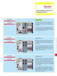
Microcontroller MC - Bosch Rexroth
Microcontroller MC - Bosch Rexroth
Microcontroller MC - Bosch Rexroth

You also want an ePaper? Increase the reach of your titles
YUMPU automatically turns print PDFs into web optimized ePapers that Google loves.
RE 95 050/05.00<br />
RE 95 050/05.00<br />
Replaces: 05.99<br />
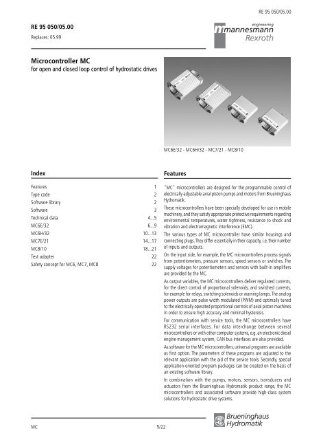
<strong>Microcontroller</strong> <strong>MC</strong><br />
for open and closed loop control of hydrostatic drives<br />
<strong>MC</strong>6E/32 - <strong>MC</strong>6H/32 - <strong>MC</strong>7/21 - <strong>MC</strong>8/10<br />
Index<br />
Features 1<br />
Type code 2<br />
Software library 2<br />
Software 3<br />
Technical data 4...5<br />
<strong>MC</strong>6E/32 6...9<br />
<strong>MC</strong>6H/32 10...13<br />
<strong>MC</strong>7E/21 14...17<br />
<strong>MC</strong>8/10 18...21<br />
Test adapter 22<br />
Safety concept for <strong>MC</strong>6, <strong>MC</strong>7, <strong>MC</strong>8 22<br />
Features<br />
"<strong>MC</strong>" microcontrollers are designed for the programmable control of<br />
electrically adjustable axial piston pumps and motors from Brueninghaus<br />
Hydromatik.<br />
These microcontrollers have been specially developed for use in mobile<br />
machinery, and they satisfy appropriate protective requirements regarding<br />
environmental temperatures, water tightness, resistance to shock and<br />
vibration and electromagnetic interference (E<strong>MC</strong>).<br />
The various types of <strong>MC</strong> microcontroller have similar housings and<br />
connecting plugs. They differ essentially in their capacity, i.e. their number<br />
of inputs and outputs.<br />
On the input side, for example, the <strong>MC</strong> microcontrollers process signals<br />
from potentiometers, pressure sensors, speed sensors or switches. The<br />
supply voltages for potentiometers and sensors with built-in amplifiers<br />
are provided by the <strong>MC</strong>.<br />
As output variables, the <strong>MC</strong> microcontrollers deliver regulated currents,<br />
for the direct control of proportional solenoids, and switched currents,<br />
for example for relays, switching solenoids or warning lamps. The analog<br />
power outputs are pulse width modulated (PWM) and optimally tuned<br />
to the electrically operated proportional controls of axial piston machines<br />
in order to ensure high accuracy and minimal hysteresis.<br />
For communication with service tools, the <strong>MC</strong> microcontrollers have<br />
RS232 serial interfaces. For data interchange between several<br />
microcontrollers or with other computer systems, e.g. an electronic diesel<br />
engine management system, CAN bus interfaces are also provided.<br />
As software for the <strong>MC</strong> microcontrollers, universal programs are available<br />
as first option. The parameters of these programs are adjusted to the<br />
relevant application with the aid of the service tools. Secondly, special<br />
application-oriented program packages can be created on the basis of<br />
an existing software library.<br />
In combination with the pumps, motors, sensors, transducers and<br />
actuators from the Brueninghaus Hydromatik product range, the <strong>MC</strong><br />
microcontrollers and associated software provide high-class system<br />
solutions for hydrostatic drive systems.<br />
<strong>MC</strong> 1/22
RE 95 050/05.00<br />
Ordering Code<br />
Type<br />
<strong>Microcontroller</strong> <strong>MC</strong> 6 7 8<br />
<strong>MC</strong> /<br />
Construction<br />
standard – – S<br />
with actuator output – – M<br />
extended, with actuator output and CAN bus<br />
E<br />
half format, with actuator output and CAN bus – – H<br />
Series/Index<br />
32 21 10<br />
● = available – = not available<br />
Note: <strong>Microcontroller</strong> <strong>MC</strong> cannot be used without software.<br />
Brueninghaus Hydromatik provides software packages for an extremely wide variety of applications.<br />
Software Library<br />
Software<br />
function<br />
module<br />
(1) Automotive driving<br />
(2) Constant preset<br />
engine speed<br />
(3) Constant Speed Drive CSD<br />
(4) Hydrostatic braking<br />
(5) Reversing<br />
(6) Inching<br />
(7) Load limiting control GLR<br />
(8) Tractive force limitation<br />
(9) Speed-dependent tractive force<br />
(10) Automatic gear change SGM<br />
(11) Synchronous dual-circuit drive<br />
(12) Anti slip control ASR<br />
(13) Safety monitoring with<br />
hardware fault detection<br />
(14) Parameter setting, diagnostics<br />
Typical<br />
applications<br />
●<br />
❍<br />
❍<br />
●<br />
●<br />
●<br />
●<br />
❍<br />
❍<br />
❍<br />
●<br />
●<br />
●<br />
●<br />
●<br />
●<br />
●<br />
●<br />
❍<br />
●<br />
●<br />
●<br />
●<br />
●<br />
●<br />
●<br />
❍<br />
●<br />
Municipal vehicles<br />
Forestry machinery<br />
Sweeping machines<br />
Fork lift trucks<br />
Wheel loaders<br />
Backhoe<br />
●<br />
●<br />
●<br />
●<br />
●<br />
●<br />
❍<br />
●<br />
●<br />
●<br />
●<br />
●<br />
●<br />
●<br />
●<br />
●<br />
❍<br />
●<br />
●<br />
❍<br />
❍<br />
●<br />
●<br />
●<br />
●<br />
●<br />
●<br />
❍<br />
❍<br />
●<br />
●<br />
●<br />
●<br />
●<br />
●<br />
●<br />
●<br />
●<br />
●<br />
●<br />
●<br />
●<br />
●<br />
●<br />
●<br />
●<br />
●<br />
●<br />
●<br />
●<br />
❍<br />
●<br />
●<br />
●<br />
Crawler and dozer<br />
Road finishing machines<br />
Mobile cranes<br />
Straddle carrier<br />
Excavators<br />
●<br />
●<br />
●<br />
●<br />
●<br />
●<br />
●<br />
●<br />
❍<br />
●<br />
●<br />
●<br />
● standard<br />
❍ optional<br />
Other<br />
applications<br />
available on<br />
request<br />
Software product<br />
Note:<br />
Typical hardware<br />
applications<br />
FGR<br />
FGR<br />
<strong>MC</strong>8<br />
<strong>MC</strong>7<br />
<strong>MC</strong>7<br />
<strong>MC</strong>8<br />
FGR<br />
FGR<br />
FGR<br />
FGR<br />
<strong>MC</strong>7<br />
<strong>MC</strong>7<br />
<strong>MC</strong>6<br />
<strong>MC</strong>6<br />
FZA<br />
<strong>MC</strong>6<br />
FZA<br />
ASR<br />
<strong>MC</strong>6<br />
<strong>MC</strong>7<br />
For optimisation of software commissioning may need to be carried out by Brueninghaus Hydromatik!<br />
ASR<br />
GLB<br />
Brueninghaus Hydromatik 2/22 <strong>MC</strong>
RE 95 050/05.00<br />
Software (RE documentation available on request)<br />
Electronic load limiting control for excavators (see RE 95072)<br />
Software GLB<br />
– Optimum utilisation of power from the engine in every operating mode<br />
– Load limiting control with any speeds and different power modes<br />
– Additional functions, such as rotating mechanism control, increased lifting loads and temperature-dependent power reduction<br />
Electronic drive control for municipal vehicles (see RE 95059)<br />
Driving software with load limiting control FGR<br />
– Automotive driving with optimum acceleration, deceleration and reversing<br />
– Accurate driving control with preset engine speed and load limiting control for operations such as sweeping, mowing and<br />
snow-clearing<br />
– Fast and accurate load limiting control<br />
– Additional functions such as tractive force limiting and automatic gear change<br />
Electronic drive control for track drives (see RE 95065)<br />
Driving software for dual-circuit drives FZA<br />
– Control of speed for accurate forward movement and curve control<br />
– Automotive driving with optimum acceleration, deceleration and reversing<br />
– Safety monitoring and emergency actions<br />
– Load limiting control and additional functions e.g. control of work functions<br />
Electronic drive control for fork lift trucks (see RE 95057)<br />
Driving software with load limiting control FGR<br />
– Automotive driving with optimum fine speed control, acceleration, deceleration and reversing<br />
– Programmable dynamics of vehicle movement and load limiting control for the engine<br />
– Automotive speed increase when actuating the implement functions under retention of the drive speed<br />
(Constant speed drive CSD)<br />
– Gear changing of wheel motors under load<br />
Electronic drive control for wheel loaders (see RE 95058)<br />
Driving software with load limiting control FGR and automatic gear change SGM<br />
– Automotive driving with optimum acceleration, deceleration and reversing<br />
– Speed-dependent tractive force<br />
– Load limiting control of engine for every operating mode<br />
– Automatic gear change (SGM)<br />
Electronic drive control for vehicles with single wheel drive (see RE 95070)<br />
Driving software with load limiting control FGR and anti slip control ASR<br />
– Automotive driving with optimum acceleration, deceleration and reversing<br />
– Load limiting control of engine<br />
– Anti slip control to prevent slipping of drive wheels<br />
Pump/Motor control (see RD 95077)<br />
Software PMS<br />
– Pump / motor sequential control adjustment<br />
– Control characteristics programmable with control panel BB-3<br />
– Programmable time-delay functions for the output signals<br />
Constant Speed Drive<br />
Software CSD<br />
– Open loop controlled constant drive speed, independent of the diesel engine speed<br />
– Operated (increase or reduction of drive speed) by push-buttons<br />
(in preparation)<br />
<strong>MC</strong> 3/22 Brueninghaus Hydromatik
RE 95 050/05.00<br />
Technical Data<br />
Type <strong>MC</strong>6E/32 <strong>MC</strong>6H/32 <strong>MC</strong>7S/21 <strong>MC</strong>7M/21 <strong>MC</strong>7E/21 <strong>MC</strong>8E/10<br />
Nominal voltage<br />
Supply voltage<br />
12 V, 24 V<br />
10 V...33 V DC<br />
Residual ripple (DIN 40839, part 1)<br />
max. ± 2 V<br />
Overall current consumption: approx. approx. approx.<br />
without load 500 mA 250 mA approx. 250 mA 250 mA<br />
with max. load < 30 A < 15 A < 15 A < 10 A<br />
Internal fuse(s)<br />
none<br />
External fuse protection 30 A 20 A 15 A 15 A<br />
No. of:<br />
analogue inputs 1 ) 10 6 7 4<br />
switched inputs 12 6 6 6<br />
speed inputs 8 4 3 2<br />
proportional solenoid outputs (PWM) 12 6 4 3<br />
switched outputs 6 3 2 1<br />
actuator outputs 2 ) (bidirectional PWM) 2 1 – 1 3 ) 1 3 ) 1<br />
analogue outputs (voltage) 2 1 1 3 ) 1<br />
RS 232 interfaces for BB-3 4 ) 2 1 1 1<br />
or "BODEM" PC software 2 1 1 1<br />
CAN bus interfaces 5 ) 2 1 – – 1 1<br />
Fault detection 6 ):<br />
for potentiometer inputs (no.) 8 4 2 4<br />
for solenoid outputs (no.)<br />
all solenoid outputs<br />
Analog inputs: Voltage range 0,05 ... 4,95 V 0 ... 5 V 0,05 ... 4,95 V<br />
Switch inputs, programmable high active or low active 7 )<br />
Supply voltage for potentiometers<br />
5 V<br />
Resistance value for external potentiometers 6 )<br />
2,5 kΩ...5 kΩ<br />
Supply voltage for sensors +5 V / 30 mA +5 V / 20 mA +5 V / 20 mA<br />
Speed inputs:<br />
Input voltage<br />
≥ 1 V eff<br />
Frequency range<br />
1 Hz...11 kHz<br />
Proportional solenoid outputs:<br />
100 or<br />
Pulse frequency (PWM) 100 or 200 Hz 8 ) 100 or 200 Hz 9 ) 200 Hz 10 )<br />
Current range (load-dependent)<br />
Switch outputs, maximum current<br />
Actuator outputs:<br />
PWM frequency<br />
Maximum continuous current<br />
Analog outputs, voltage range<br />
0...1,8 A<br />
1,3 A<br />
300 Hz<br />
±2,7 A<br />
0,5 ... 4,5 V (load R ≥10 kΩ)<br />
Microprocessors 2 x C167 1 x C167 C517A C167<br />
Memory capacity:<br />
RAM 2 x 1 MBit 1 MBit 256 kBit 1 MBit<br />
EPROM oder – – 512 kBit –<br />
Flash-EPROM 2 x 4 MBit 4 MBit – 1 MBit<br />
EEPROM 2 x 16 kBit 16 kBit 8 kBit 16 kBit<br />
Brueninghaus Hydromatik 4/22 <strong>MC</strong>
RE 95 050/05.00<br />
Technical Data<br />
Type <strong>MC</strong>6E/32 <strong>MC</strong>6H/32 <strong>MC</strong>7S/21 <strong>MC</strong>7M/21 <strong>MC</strong>7E/21 <strong>MC</strong>8E/10<br />
Electromagnetic compatibility (E<strong>MC</strong>)<br />
line traced interference, electromagnetic interference immunity,<br />
interference emission, electrostatic discharge<br />
ISO 7637, european motor vehicle directive 95/94 EC pr EN 13309, increased immunity 11 )<br />
Protection against short circuit to<br />
supply voltage and ground all in-/outputs 12 )<br />
Permissible short-circuit current for<br />
internal connections<br />
15A short term (
RE 95 050/05.00<br />
<strong>MC</strong>6E/32<br />
The <strong>MC</strong>6E/32 microcontroller is used for the programmable control<br />
of a maximum of twelve proportional solenoids and six additional<br />
switching functions. It can therefore be used to provide open or closed<br />
loop control of complex drive systems with a single electronic unit.<br />
For more extensive requirements, the <strong>MC</strong>6E/32 can be expanded by<br />
additional microcontrollers connected by CAN bus.<br />
Internally, the <strong>MC</strong>6E/32 microcontroller consists of two identical circuit<br />
boards, each with a digital computing circuit and the analog circuits<br />
for the inputs and outputs. The two cards are connected to each<br />
other by a high-speed internal data communication link.<br />
As input signals, the microcontroller processes analog voltages in<br />
the 0V to 5V range and switching information. All inputs are protected<br />
against overvoltage and electric interference. The potentiometer inputs<br />
are equipped with monitoring circuits to detect cable breaks or short<br />
circuits.<br />
As output signals, the output stages of the <strong>MC</strong>6E/32 deliver closed<br />
loop controlled currents for the connection of proportional solenoids<br />
for adjusting pumps, motors or valves. Additional power outputs are<br />
provided for directly switching relays, lamps and switching solenoids.<br />
Two special PWM outputs each generate bidirectional currents for<br />
controlling STM actuator (RE 95120) for operating diesel engine fuel<br />
injection pumps.<br />
Two analog voltage outputs are provided for the simple forwarding<br />
of analog information to other electronic circuits.<br />
The RS232 serial interfaces permit connection either to the BB-3<br />
control panel (RE 29798 and RE 95080-B) or to a personal computer<br />
running the BODEM PC software (RE 95085) for service functions<br />
such as diagnostics, parameter setting or process variable display.<br />
Two separate CAN bus interfaces are available on the <strong>MC</strong>6E/32<br />
microcontroller for data interchange with other <strong>MC</strong> microcontrollers<br />
or other control units (e.g. diesel engine fuel injection, display or<br />
other special working functions).<br />
The software created and installed by Brueninghaus Hydromatik in<br />
the <strong>MC</strong> microcontroller is application specific. The associated product<br />
documentation contains the function description, setting specifications<br />
and diagnostic information.<br />
Special characteristics<br />
– High computing power and short program cycle times due to<br />
powerful 16-bit processors<br />
– High electromagnetic compatibility (E<strong>MC</strong>)<br />
– Fault detection at inputs and outputs for safety monitoring and<br />
diagnostics<br />
– Safety features, such as redundant input channels, separate<br />
voltage supply for the computing circuit and output amplifiers<br />
and central safety cut-out for all outputs<br />
– Pulse width modulated (PWM) solenoid currents for minimal<br />
hysteresis<br />
– Closed loop control of solenoid currents, i.e. independent of<br />
voltage and temperature<br />
– Application-specific functions by programming<br />
Main components<br />
– Mobile computer with 16-bit microcontroller module<br />
– Protected watchdog for program run monitoring<br />
– RS232 serial data interface for diagnostics, parameterization<br />
and process variable display<br />
– 2 separate CAN bus interfaces<br />
– Voltage supply and ground connections for potentiometers and<br />
sensors<br />
– Sturdy, sealed aluminum housing<br />
– Robust connector design. Watertight with suitable mating<br />
connector<br />
Brueninghaus Hydromatik 6/22 <strong>MC</strong>
RE 95 050/05.00<br />
<strong>MC</strong>6E/32 - Block Circuit Diagram<br />
Battery<br />
+<br />
Central safety<br />
cut-out<br />
Battery<br />
Speed<br />
inputs 1 )<br />
Analog<br />
inputs 1 )<br />
Switch<br />
inputs 1 )<br />
Switch<br />
inputs 1 )<br />
Analog<br />
inputs 1 )<br />
Speed<br />
inputs 1 )<br />
Battery<br />
+<br />
-<br />
1<br />
3<br />
2<br />
4<br />
1<br />
3<br />
5<br />
2<br />
4<br />
1<br />
3<br />
5<br />
2<br />
4<br />
6<br />
6<br />
4<br />
2<br />
5<br />
3<br />
1<br />
4<br />
2<br />
5<br />
3<br />
1<br />
4<br />
2<br />
3<br />
1<br />
-<br />
+<br />
Voltage<br />
supply<br />
Inputs<br />
Speed<br />
group 1 1 )<br />
Speed<br />
group 2 1 )<br />
Analog<br />
group 1 1 )<br />
Analog<br />
group 2 1 )<br />
Switch<br />
group 1 1 )<br />
Switch<br />
group 2 1 )<br />
Switch<br />
group 3 1 )<br />
Switch<br />
group 4 1 )<br />
Analog<br />
group 3 1 )<br />
Analog<br />
group 4 1 )<br />
Speed<br />
group 3 1 )<br />
Speed<br />
group 4 1 )<br />
Inputs<br />
Voltage<br />
supply<br />
Counter<br />
inputs<br />
A/D-converter<br />
10 bit<br />
Digital<br />
inputs<br />
Digital<br />
inputs<br />
A/D-converter<br />
10 bit<br />
Counter<br />
inputs<br />
Monitoring<br />
watchdog<br />
<strong>Microcontroller</strong> 16 Bit<br />
Flash-<br />
EPROM<br />
4 MBit<br />
EEPROM<br />
16 kBit<br />
RAM<br />
1 MBit<br />
Control unit<br />
for outputs<br />
Interface<br />
controller<br />
Interface<br />
controller<br />
Control unit<br />
for outputs<br />
Flash- EEPROM RAM<br />
EPROM 16 kBit 1 MBit<br />
4 MBit<br />
<strong>Microcontroller</strong> 16 Bit<br />
Monitoring<br />
watchdog<br />
Status feedback<br />
from all<br />
outputs<br />
D/A<br />
converter<br />
Internal<br />
data interface<br />
D/A<br />
converter<br />
Status feedback<br />
from all<br />
outputs<br />
PWM output<br />
stages<br />
Switch output<br />
stages<br />
H bridge<br />
Outputs<br />
Interface<br />
driver<br />
Interface<br />
driver<br />
Outputs<br />
H bridge<br />
Switch output<br />
stages<br />
PWM output<br />
stages<br />
1<br />
2<br />
3<br />
4<br />
5<br />
6<br />
1<br />
2<br />
3<br />
1<br />
1<br />
1<br />
1<br />
1<br />
1<br />
1<br />
1<br />
3<br />
2<br />
1<br />
6<br />
5<br />
4<br />
3<br />
2<br />
1<br />
Proportional<br />
solenoid<br />
outputs<br />
Switch outputs<br />
Output for STM<br />
actuator<br />
Analog signal<br />
output<br />
RS232 serial<br />
interface<br />
CAN bus<br />
interface<br />
CAN bus<br />
interface<br />
RS232 serial<br />
interface<br />
Analog signal<br />
output<br />
Output for STM<br />
actuator<br />
Switch outputs<br />
Proportional<br />
solenoid<br />
outputs<br />
Battery<br />
+<br />
Central safety<br />
cut-out<br />
1<br />
) Inputs for safety-related functions should be configured with sufficient redundancy.<br />
The group 1 and group 2 inputs are mutually isolated by the technical circuitry.<br />
<strong>MC</strong> 7/22 Brueninghaus Hydromatik
RE 95 050/05.00<br />
<strong>MC</strong>6E/32 - Terminal Connection Diagram<br />
This connection diagram is an example. Application-specific connection diagrams can be produced on request.<br />
fuse<br />
Connector A<br />
Connector B<br />
1 A<br />
emergency stop<br />
+12V/<br />
+24V<br />
0V/<br />
ground<br />
speed sensors<br />
1<br />
2<br />
3<br />
4<br />
30A<br />
fuse<br />
A1<br />
A28<br />
A2<br />
A3<br />
A30<br />
A13<br />
A41<br />
A14<br />
A43<br />
A15<br />
A44<br />
A16<br />
supply for power<br />
outputs<br />
voltage<br />
supply<br />
A32<br />
A5<br />
A33<br />
A6<br />
A34<br />
4)<br />
4)<br />
4)<br />
4)<br />
1<br />
2<br />
3<br />
4<br />
5<br />
proportional solenoids<br />
1<br />
2<br />
3<br />
4<br />
5<br />
4)<br />
4)<br />
4)<br />
4)<br />
B32<br />
B5<br />
B33<br />
B6<br />
B34<br />
supply for power<br />
outputs<br />
voltage<br />
supply<br />
B1<br />
B28<br />
B2<br />
B3<br />
B30<br />
B13<br />
B41<br />
B14<br />
B43<br />
B15<br />
B44<br />
B16<br />
1<br />
2<br />
3<br />
4<br />
speed sensors<br />
potentiometers<br />
4)<br />
A17<br />
A35<br />
4) B35<br />
B17<br />
A18 +4,5V<br />
+4,5V B18<br />
1<br />
A19<br />
6<br />
6<br />
B19<br />
4)<br />
4)<br />
2<br />
A45 +4,5V<br />
+4,5V B45<br />
A46<br />
B46<br />
A47<br />
B47<br />
A36<br />
B36<br />
3<br />
A20 +4,5V<br />
1<br />
1<br />
+4,5V B20<br />
A21<br />
B21<br />
A22<br />
A37<br />
4)<br />
4)<br />
B22<br />
B37<br />
4<br />
A48 +4,5V<br />
2<br />
2<br />
+4,5V B48<br />
A49<br />
B49<br />
A50<br />
A38 4)<br />
4)<br />
B50<br />
B38<br />
+ 3<br />
3<br />
+<br />
A24<br />
B24<br />
5<br />
A25<br />
4)<br />
4)<br />
B25<br />
fault detection for<br />
2.5kΩ...5kΩ potentiometers<br />
switching solenoids, relays,<br />
lamps<br />
fault detection for<br />
2.5kΩ...5kΩ potentiometers<br />
1<br />
2<br />
3<br />
4<br />
5<br />
potentiometers<br />
sensor<br />
supply<br />
switches<br />
{<br />
1<br />
2<br />
3<br />
4<br />
5<br />
6<br />
A23<br />
A7<br />
A8<br />
A9<br />
A10<br />
A11<br />
A12<br />
A52<br />
5)<br />
5)<br />
5)<br />
5)<br />
5)<br />
5)<br />
1 ) Short, low-resistance connection from the housing to the vehicle<br />
ground<br />
2) The BB-3 connecting cable or BODEM connecting cable are not<br />
included. Available from Brueninghaus Hydromatik on request<br />
3) The CANNON TRIDENT diagnostic connector, comprising:<br />
– Standard receptacle for female contacts 192990-1670<br />
– 8 gold-plated female contacts 192922-1470<br />
– Cable clamp, version HC 192990-1540<br />
– Protective cap for connector 192992-1490<br />
is not included with the microcontroller.<br />
Available from Brueninghaus Hydromatik on request.<br />
+5V<br />
1)<br />
TxD<br />
RxD<br />
CAN H<br />
CAN L<br />
A4<br />
A31<br />
A40<br />
A42<br />
A39<br />
A26<br />
A27<br />
A55<br />
M_<br />
STM actuator<br />
A53<br />
B53<br />
analog... analog...<br />
or 5 ) A25<br />
B25<br />
or<br />
0V...5V 0V...5V<br />
5 )<br />
coding for<br />
plug A<br />
RS 232<br />
CAN bus<br />
RS 232<br />
M_<br />
C<br />
D<br />
B<br />
E<br />
A<br />
G<br />
F<br />
3)<br />
B4<br />
B31<br />
B40<br />
B42<br />
B39<br />
CAN bus<br />
B26<br />
B27<br />
B55<br />
TxD<br />
RxD<br />
CAN H<br />
CAN L<br />
2)<br />
5)<br />
5)<br />
5)<br />
5)<br />
5)<br />
5)<br />
BB-3<br />
4 ) Separate ground connection to battery (chassis also possible)<br />
5) Pull-up or pull-down programmable for these inputs.<br />
Consequently, the switch inputs (all together) must be switched<br />
either to +12V/24V or to ground, depending on the application.<br />
Note to 2) and 3):<br />
When connecting or disconnecting the BB3-connecting cable or<br />
BODEM-connecting cable, <strong>MC</strong> and PC have to be switched off!<br />
+5V<br />
B23<br />
B7<br />
B8<br />
B9<br />
B10<br />
B11<br />
B12<br />
B52<br />
1<br />
2<br />
3<br />
4<br />
5<br />
6<br />
coding for<br />
plug B<br />
BB-3 control panel<br />
or<br />
PC with<br />
BODEM software<br />
{<br />
sensor<br />
supply<br />
switches<br />
Brueninghaus Hydromatik 8/22 <strong>MC</strong>
RE 95 050/05.00<br />
<strong>MC</strong>6E/32 - Unit Dimensions<br />
approx. ca.<br />
Connector<br />
A<br />
Connector<br />
B<br />
Mating connector<br />
(not included)<br />
Mating connector<br />
(not included)<br />
Plug Contacts<br />
1<br />
27<br />
28 55<br />
The 2 AMP timer connectors for <strong>MC</strong>6E/32,<br />
each consisting of:<br />
– Timer hybrid housing 0185887-1<br />
– 8 junior power timer contacts 927771-1<br />
– 47 micro timer type 4 contacts 185158-1<br />
are not included with the microcontroller.<br />
Available from Brueninghaus Hydromatik on request.<br />
Setting and Display Facilities<br />
All calibration operations and the display of functions, faults and<br />
system variables are connected via the serial interface to the BB-3<br />
control panel (RE 29798 and RE 95080-B) or to a PC running the<br />
BODEM software (RE 95085).<br />
<strong>MC</strong> 9/22 Brueninghaus Hydromatik
RE 95 050/05.00<br />
<strong>MC</strong>6H/32<br />
The <strong>MC</strong>6H/32 contains only one circuit board, which is identical to<br />
the two in the <strong>MC</strong>6E/32.<br />
Consequently, the <strong>MC</strong>6H/32 is suitable for controlling a maximum of<br />
six proportional solenoids and three additional switching functions.<br />
For example, it can provide the complete open loop control of simple<br />
dual-circuit drive systems for tracked vehicles.<br />
As input signals, the microcontroller processes analog voltages in<br />
the 0V to 5V range and switching information. All inputs are protected<br />
against overvoltage and electric interference. The potentiometer inputs<br />
are equipped with monitoring circuits to detect cable breaks or short<br />
circuits.<br />
As output signals, the output stages of the <strong>MC</strong>6H/32 deliver closed<br />
loop controlled currents for the connection of proportional solenoids<br />
for adjusting pumps, motors or valves. Additional power outputs are<br />
provided for directly switching relays, lamps and switching solenoids.<br />
A special PWM output generates a bidirectional current for controlling<br />
STM actuator (RE 95120) for operating diesel engine fuel injection<br />
pumps.<br />
The analog voltage output is suitable for the simple forwarding of<br />
analog information to other electronic circuits.<br />
The RS232 serial interface permits connection either to the BB-3<br />
control panel (RE 29798 and RE 95080-B) or to a personal computer<br />
running the BODEM PC software (RE 95085) for service functions<br />
such as diagnostics, parameter setting or process variable display.<br />
A CAN bus interface is available on the <strong>MC</strong>6H/32 for data interchange<br />
with other <strong>MC</strong> microcontrollers or other control units (e.g. diesel<br />
engine fuel injection, display or special work functions).<br />
The software created and installed by Brueninghaus Hydromatik in<br />
the <strong>MC</strong> microcontroller is application specific. The associated product<br />
documentation contains the function description, setting specifications<br />
and diagnostic information.<br />
Special characteristics<br />
– High computing power and short program cycle times with a<br />
powerful 16-bit processor.<br />
– High electromagnetic compatibility (E<strong>MC</strong>)<br />
– Fault detection at inputs and outputs for safety monitoring and<br />
diagnostics<br />
– Safety features, such as redundant input channels, separate<br />
voltage supply for the computing circuit and output amplifiers<br />
and central safety cut-out for all outputs<br />
– Pulse width modulated (PWM) solenoid currents for minimal<br />
hysteresis<br />
– Closed loop control of solenoid currents, i.e. independent of<br />
voltage and temperature<br />
– Application-specific functions by programming<br />
Main components<br />
– Mobile computer with a 16-bit microcontroller module<br />
– Protected watchdog for program run monitoring<br />
– RS232 serial data interface for diagnostics, parameterization<br />
and process variable display<br />
– CAN bus interface<br />
– Voltage supply and ground connections for potentiometers and<br />
sensors<br />
– Sturdy, sealed aluminum housing<br />
– Robust connector design. Watertight with suitable mating<br />
connector<br />
Brueninghaus Hydromatik 10/22 <strong>MC</strong>
RE 95 050/05.00<br />
<strong>MC</strong>6H/32 - Block Circuit Diagram<br />
Battery<br />
+<br />
Central safety<br />
cut-out<br />
Battery<br />
Speed<br />
inputs 1 )<br />
Analog<br />
inputs 1 )<br />
Switch<br />
inputs 1 )<br />
+<br />
-<br />
1<br />
3<br />
2<br />
4<br />
1<br />
3<br />
5<br />
2<br />
4<br />
6<br />
1<br />
3<br />
5<br />
2<br />
4<br />
6<br />
Voltage<br />
supply<br />
Inputs<br />
Speed<br />
group 1 1 )<br />
Speed<br />
group 2 1 )<br />
Analog<br />
group 1 1 )<br />
Analog<br />
group 2 1 )<br />
Switch<br />
group 1 1 )<br />
Switch<br />
group 2 1 )<br />
Counter<br />
inputs<br />
A/D-converter<br />
10 bit<br />
Digital<br />
inputs<br />
Monitoring<br />
watchdog<br />
<strong>Microcontroller</strong> 16 Bit<br />
Flash-<br />
EPROM<br />
4 MBit<br />
EEPROM<br />
16 kBit<br />
RAM<br />
1 MBit<br />
Control unit<br />
for outputs<br />
Interface<br />
controller<br />
Status feedback<br />
from all<br />
outputs<br />
D/A<br />
converter<br />
PWM output<br />
stages<br />
Switch output<br />
stages<br />
H bridge<br />
Outputs<br />
Interface<br />
driver<br />
1<br />
2<br />
3<br />
4<br />
5<br />
6<br />
1<br />
2<br />
3<br />
1<br />
1<br />
1<br />
1<br />
Proportional<br />
solenoid<br />
outputs<br />
Switch outputs<br />
Output for STM<br />
actuator<br />
Analog signal<br />
output<br />
RS232 serial<br />
interface<br />
CAN bus<br />
interface<br />
1<br />
) Inputs for safety-related functions should be configured with sufficient redundancy.<br />
The group 1 and group 2 inputs are mutually isolated by the technical circuitry.<br />
<strong>MC</strong> 11/22 Brueninghaus Hydromatik
RE 95 050/05.00<br />
<strong>MC</strong>6H/32 - Terminal Connection Diagram<br />
This connection diagram is an example. Application-specific connection diagrams can be produced on request.<br />
fuse<br />
1 A<br />
emergency stop<br />
+12V/+24V<br />
0V/ground<br />
speed sensors<br />
15A<br />
fuse<br />
1<br />
2<br />
1<br />
28<br />
2<br />
3<br />
30<br />
13<br />
41<br />
14<br />
43<br />
supply for power<br />
outputs<br />
voltage<br />
supply<br />
32<br />
5<br />
33<br />
4)<br />
4)<br />
1<br />
2<br />
3<br />
proportional solenoids<br />
3<br />
4<br />
15<br />
44<br />
16<br />
6<br />
34<br />
4)<br />
4)<br />
4<br />
5<br />
potentiometers<br />
sensor supply<br />
switches<br />
1<br />
2<br />
3<br />
4<br />
5<br />
6<br />
or 5 )<br />
+<br />
+<br />
{<br />
1<br />
2<br />
3<br />
4<br />
5<br />
6<br />
17<br />
18<br />
19<br />
45<br />
46<br />
47<br />
20<br />
21<br />
22<br />
48<br />
49<br />
50<br />
24<br />
25<br />
52<br />
23<br />
7<br />
8<br />
9<br />
10<br />
11<br />
12<br />
+4,5V<br />
+4,5V<br />
+4,5V<br />
+4,5V<br />
+5V<br />
5)<br />
5)<br />
5)<br />
5)<br />
5)<br />
5)<br />
fault detection for<br />
2.5kΩ...5kΩ potentiometers<br />
TxD<br />
RxD<br />
CAN H<br />
CAN L<br />
35<br />
36<br />
37<br />
38<br />
4<br />
31<br />
53<br />
25<br />
4)<br />
4)<br />
4)<br />
4)<br />
4)<br />
6<br />
1<br />
2<br />
3<br />
M_<br />
analog...<br />
0V...5V<br />
switching solenoids, relays,<br />
lamps<br />
STM actuator<br />
40 C<br />
42<br />
D<br />
39<br />
B<br />
E<br />
RS 232<br />
A<br />
G<br />
F<br />
26<br />
27<br />
3)<br />
55<br />
2)<br />
BB-3<br />
BB-3 control panel<br />
or<br />
PC with<br />
BODEM software<br />
CAN bus<br />
1)<br />
1 ) Short, low-resistance connection from the housing to the vehicle<br />
ground<br />
2) The BB-3 connecting cable or BODEM connecting cable are not<br />
included. Available from Brueninghaus Hydromatik on request<br />
3) The CANNON TRIDENT diagnostic connector, comprising:<br />
– Standard receptacle for female contacts 192990-1670<br />
– 8 gold-plated female contacts 192922-1470<br />
– Cable clamp, version HC 192990-1540<br />
– Protective cap for connector 192992-1490<br />
is not included with the microcontroller.<br />
Available from Brueninghaus Hydromatik on request.<br />
4 ) Separate ground connection to battery (chassis also possible)<br />
5) Pull-up or pull-down programmable for these inputs.<br />
Consequently, the switch inputs (all together) must be switched<br />
either to +12V/24V or to ground, depending on the application.<br />
Note to 2) and 3):<br />
When connecting or disconnecting the BB3-connecting cable or<br />
BODEM-connecting cable, <strong>MC</strong> and PC have to be switched off!<br />
Brueninghaus Hydromatik 12/22 <strong>MC</strong>
RE 95 050/05.00<br />
<strong>MC</strong>6H/32 - Unit Dimensions<br />
➤<br />
➤<br />
➤<br />
➤<br />
235<br />
ca. 400<br />
approx.<br />
5,25 15<br />
7,5<br />
➤<br />
➤<br />
➤<br />
➤<br />
➤<br />
➤<br />
➤<br />
➤<br />
➤<br />
Mating connector<br />
(not included)<br />
51<br />
➤<br />
159<br />
177<br />
187<br />
➤<br />
7,5<br />
➤<br />
➤<br />
➤<br />
283<br />
➤<br />
➤<br />
Plug Contacts<br />
1<br />
27<br />
28 55<br />
The AMP timer connector for <strong>MC</strong>6H/32, consisting of:<br />
– Timer hybrid housing 0185887-1<br />
– 8 junior power timer contacts 927771-1<br />
– 47 micro timer type 4 contacts 185158-1<br />
are not included with the microcontroller.<br />
Available from Brueninghaus Hydromatik on request.<br />
Setting and Display Facilities<br />
All calibration operations and the display of functions, faults and<br />
system variables are connected via the serial interface to the BB-3<br />
control panel (RE 29798 and RE 95080-B) or to a PC running the<br />
BODEM software (RE 95085).<br />
<strong>MC</strong> 13/22 Brueninghaus Hydromatik
RE 95 050/05.00<br />
<strong>MC</strong>7E/21<br />
The <strong>MC</strong>7E/21 microcontroller is used for the programmable control<br />
of a maximum of four proportional solenoids and two additional<br />
switching functions. It is therefore for example suitable for the open<br />
or closed loop control of a hydrostatic drive transmission for mobile<br />
machinery. For more extensive requirements, the <strong>MC</strong>6/32<br />
microcontroller, for example, can be used.<br />
Internally, the <strong>MC</strong>7E/21 microcontroller consists of two circuit boards:<br />
one "processor card" with the computing section and one "peripheral<br />
card" with the analog circuits for the inputs and outputs.<br />
As input signals, the microprocessor processes analog voltages in<br />
the 0V to 5V range and switching information. All inputs are protected<br />
against overvoltage and electrical interference. Two of the<br />
potentiometer inputs are equipped with monitoring circuits to detect<br />
any cable break or short circuit.<br />
As output signals, the output stages of the <strong>MC</strong>7E/21 deliver closed<br />
loop controlled currents for the connection of proportional solenoids<br />
for adjusting pumps, motors or valves. Additional power outputs are<br />
provided for directly switching relays, lamps and switching solenoids.<br />
A special PWM output generates a bidirectional current for controlling<br />
STM actuator (RE 95120) for operating diesel engine fuel injection<br />
pumps.<br />
The analog voltage output is suitable for the simple forwarding of<br />
analog information to other electronic circuits.<br />
The RS232 serial interface permits connection either to the BB-3<br />
control panel (RE 29798 and RE 95080-B) or to a personal computer<br />
running the BODEM PC software (RE 95085) for service functions<br />
such as diagnostics, parameter setting or process variable display.<br />
A CAN bus interface is available on the <strong>MC</strong>7/21 for data interchange<br />
with other <strong>MC</strong> microcontrollers or other control units (e.g. diesel<br />
engine fuel injection, display or special work functions).<br />
The software created and installed by Brueninghaus Hydromatik in<br />
the <strong>MC</strong> microcontroller is application specific. The associated product<br />
documentation contains the function description, setting specifications<br />
and diagnostic information.<br />
Special characteristics<br />
– Robust design with specifications for mobile applications.<br />
– High electromagnetic compatibility (E<strong>MC</strong>)<br />
– Inputs and outputs available with fault detection<br />
– Safety features, such as redundant inputs and central safety<br />
cut-out of all outputs<br />
– Pulse width modulated (PWM) solenoid currents for minimal<br />
hysteresis<br />
– Closed loop control of solenoid currents, i.e. independent of<br />
voltage and temperature<br />
– Application-specific functions by programming<br />
Main components<br />
– Mobile computer with 8-bit microcontroller<br />
– Protected watchdog for program run monitoring<br />
– RS232 serial data interface for diagnostics, parameterization<br />
and process variable display<br />
– CAN bus interface<br />
– Voltage supply and ground connections for potentiometers and<br />
sensors<br />
– Internal buzzer for programmable monitoring of functions or<br />
errors<br />
– Sturdy, sealed aluminum housing<br />
– Robust connector design. Watertight with suitable mating<br />
connector<br />
Brueninghaus Hydromatik 14/22 <strong>MC</strong>
RE 95 050/05.00<br />
<strong>MC</strong>7E/21 - Block Circuit Diagram<br />
Central safety<br />
cut-out<br />
Battery<br />
Speed<br />
inputs 1 )<br />
Analog<br />
inputs 1 )<br />
Switch<br />
inputs 1 )<br />
+<br />
-<br />
0<br />
1<br />
2<br />
0<br />
1<br />
2<br />
3<br />
4<br />
5<br />
6<br />
0<br />
1<br />
2<br />
3<br />
4<br />
5<br />
Voltage<br />
supply<br />
Inputs<br />
Speed<br />
group 1 1 )<br />
Speed<br />
group 2 1 )<br />
Analog<br />
group 1 1 )<br />
Analog<br />
group 2 1 )<br />
Switch<br />
group 1 1 )<br />
Switch<br />
group 2 1 )<br />
Counter<br />
inputs<br />
A/D-converter<br />
10 bit<br />
Digital<br />
inputs<br />
Monitoring<br />
watchdog<br />
<strong>Microcontroller</strong> 8 Bit<br />
EPROM<br />
512 kBit<br />
EEPROM<br />
8 kBit<br />
RAM<br />
256 kBit<br />
Control unit<br />
for outputs<br />
Interface<br />
controller<br />
Status feedback<br />
from all<br />
outputs<br />
D/A<br />
converter<br />
PWM output<br />
stages<br />
Switch output<br />
stages<br />
H bridge<br />
Outputs<br />
Interface<br />
driver<br />
0<br />
1<br />
2<br />
3<br />
0<br />
1<br />
Proportional<br />
solenoid<br />
outputs<br />
Switch outputs<br />
Output for<br />
STM actuator 2 )<br />
Analog signal<br />
output<br />
RS232 serial<br />
interface<br />
CAN bus<br />
interface 3 )<br />
1 ) For safety-related functions, the inputs should be duplicated.<br />
The group 1 inputs are isolated by the circuitry from the group 2 inputs.<br />
2)<br />
Not applicable to <strong>MC</strong>7S/21<br />
3)<br />
Not applicable to <strong>MC</strong>7S/21 and <strong>MC</strong>7M/21<br />
<strong>MC</strong> 15/22 Brueninghaus Hydromatik
RE 95 050/05.00<br />
<strong>MC</strong>7E/21 - Terminal Connection Diagram<br />
This connection diagram is an example.<br />
Application-specific connection diagrams can be produced on request.<br />
fuse<br />
1 A<br />
emergency stop<br />
+12V / +24V<br />
0V / ground<br />
potentiometers<br />
sensor supply<br />
switches<br />
0<br />
1<br />
2<br />
0<br />
1<br />
2<br />
3<br />
+<br />
4<br />
+<br />
5<br />
+<br />
6<br />
or 5 )<br />
15 A<br />
fuse<br />
0V...5V<br />
0V...5V<br />
{<br />
0<br />
1<br />
2<br />
3<br />
4<br />
5<br />
1<br />
2<br />
3<br />
4<br />
53<br />
18<br />
54<br />
20<br />
52<br />
17<br />
44 +4,5V<br />
45<br />
22<br />
24<br />
46<br />
15<br />
25<br />
47<br />
11<br />
21<br />
48<br />
12<br />
49<br />
13<br />
50<br />
14<br />
51<br />
16<br />
23<br />
35<br />
36<br />
37<br />
38<br />
39<br />
19<br />
+4,5V<br />
+4,5V<br />
+4,5V<br />
5)<br />
5)<br />
+5V<br />
5)<br />
fault detection for<br />
2.5kΩ...5kΩ potentiometers<br />
5)<br />
5)<br />
5)<br />
5)<br />
5)<br />
5)<br />
TxD<br />
RxD<br />
28<br />
29<br />
30<br />
31<br />
32<br />
33<br />
41<br />
43<br />
34<br />
5<br />
4)<br />
4)<br />
4)<br />
4)<br />
4)<br />
4)<br />
0<br />
1<br />
2<br />
3<br />
0<br />
1<br />
M_<br />
40 C<br />
42<br />
D<br />
10<br />
B<br />
E<br />
A<br />
G<br />
F<br />
proportional<br />
solenoids<br />
switching solenoids,<br />
relays, lamps, etc.<br />
analog signal output<br />
0 V...5 V DC<br />
3)<br />
STM actuator 6 )<br />
RS 232 interfaces<br />
2)<br />
BB-3<br />
BB-3 control panel<br />
or<br />
PC with BODEM software<br />
signal ground<br />
connections<br />
(not for solenoids<br />
or battery)<br />
6<br />
7<br />
8<br />
9<br />
1)<br />
CAN H<br />
CAN L<br />
26<br />
27<br />
55<br />
CAN bus<br />
interface 7 )<br />
1 ) Short, low-resistance connection from the housing to the vehicle<br />
ground<br />
2) The BB-3 connecting cable or BODEM connecting cable, are not<br />
included. Available from Brueninghaus Hydromatik on request<br />
3) The CANNON TRIDENT diagnostic connector, comprising:<br />
– Standard receptacle for female contacts 192990-1670<br />
– 8 gold-plated female contacts 192922-1470<br />
– Cable clamp, version HC 192990-1540<br />
– Protective cap for connector 192992-1490<br />
is not included with the microcontroller.<br />
Available from Brueninghaus Hydromatik on request.<br />
4 ) Separate ground connection to battery (chassis also possible)<br />
5) Pull-up or pull-down programmable for these inputs.<br />
Consequently, the switch inputs (all together) must be switched<br />
either to +12V/24V or to ground, depending on the application.<br />
6 ) Not applicable to <strong>MC</strong>7S/21<br />
7) Not applicable to <strong>MC</strong>7S/21 and <strong>MC</strong>7M/21<br />
Note to 2) and 3):<br />
When connecting or disconnecting the BB3-connecting cable or<br />
BODEM-connecting cable, <strong>MC</strong> and PC have to be switched off!<br />
Brueninghaus Hydromatik 16/22 <strong>MC</strong>
RE 95 050/05.00<br />
<strong>MC</strong>7E/21 - Unit Dimensions<br />
Mating connector<br />
(not included)<br />
51<br />
153,2<br />
5,3 15<br />
7,5<br />
159<br />
199<br />
7,5<br />
ca.300<br />
approx.<br />
198<br />
25,5<br />
Plug Contacts<br />
1<br />
27<br />
28 55<br />
The AMP timer connector for <strong>MC</strong>7/21, consisting of:<br />
– Timer hybrid housing 0185887-1<br />
– 8 junior power timer contacts 927771-1<br />
– 47 micro timer type 4 contacts 185158-1<br />
are not included with the microcontroller.<br />
Available from Brueninghaus Hydromatik on request.<br />
Setting and Display Facilities<br />
All calibration operations and the display of functions, faults and<br />
system variables are connected via the serial interface to the BB-3<br />
control panel (RE 29798 and RE 95080-B) or to a PC running the<br />
BODEM software (RE 95085).<br />
<strong>MC</strong> 17/22 Brueninghaus Hydromatik
RE 95 050/05.00<br />
<strong>MC</strong>8/10<br />
The <strong>MC</strong>8/10 microcontroller is used for the programmable control of<br />
a maximum of three proportional solenoids and one additional<br />
switching function. It is therefore suitable for simple open or closed<br />
loop controls, e.g. for hydrostatic drive transmission for mobile<br />
machinery. For more extensive requirements, the <strong>MC</strong>7/21 or<br />
<strong>MC</strong>6/32 microcontrollers can be used.<br />
Internally, the <strong>MC</strong>8/10 microcontroller contains a high-speed<br />
16-bit processor and all input and output circuits on a single card.<br />
As input signals, the microcontroller processes analog voltages in<br />
the 0V to 5V range and switching information. All inputs are protected<br />
against overvoltage and electric interference. All potentiometer inputs<br />
are equipped with monitoring circuits to detect cable breaks or short<br />
circuits.<br />
As output signals, the output stages of the <strong>MC</strong>8/10 deliver closed<br />
loop controlled currents for the connection of proportional solenoids<br />
for adjusting pumps, motors or valves. An additional power output<br />
is provided for directly switching relays, lamps and switching<br />
solenoids.<br />
A special PWM output generates a bidirectional current for controlling<br />
STM actuators (RE 95120) for operating diesel engine fuel injection<br />
pumps.<br />
The analog voltage output is suitable for the simple forwarding of<br />
analog information to other electronic circuits.<br />
The RS232 serial interface permits connection either to the BB-3<br />
control panel (RE 29798 and RE 95080-B) or to a personal computer<br />
running the BODEM PC software (RE 95085) for service functions<br />
such as diagnostics, parameter setting or process variable display.<br />
A CAN bus interface is available on the <strong>MC</strong>8/10 for data interchange<br />
with other <strong>MC</strong> microcontrollers or other control units (e.g. diesel<br />
engine fuel injection, display or special work functions).<br />
The software created and installed by Brueninghaus Hydromatik in<br />
the <strong>MC</strong> microcontroller is application specific. The associated product<br />
documentation contains the function description, setting specifications<br />
and diagnostic information.<br />
Special characteristics<br />
– Robust design with specifications for mobile applications.<br />
– High electromagnetic compatibility (E<strong>MC</strong>)<br />
– Inputs and outputs available with fault detection<br />
– Safety features, such as redundant inputs and central safety<br />
cut-out of all outputs<br />
– Pulse width modulated (PWM) solenoid currents for minimal<br />
hysteresis<br />
– Closed loop control of solenoid currents, i.e. independent of<br />
voltage and temperature<br />
– Application-specific functions by programming<br />
Main components<br />
– Powerful 16-bit microcontroller module<br />
– Protected watchdog for program run monitoring<br />
– RS232 serial data interface for diagnostics, parameterization<br />
and process variable display<br />
– CAN bus interface<br />
– Voltage supply and ground connections for potentiometers and<br />
sensors<br />
– Sturdy, sealed aluminum housing<br />
– Robust connector design. Watertight with suitable mating<br />
connector<br />
Brueninghaus Hydromatik 18/22 <strong>MC</strong>
RE 95 050/05.00<br />
<strong>MC</strong>8/10 - Block Circuit Diagram<br />
Battery<br />
+<br />
Central safety<br />
cut-out<br />
Battery<br />
Speed<br />
inputs 1 )<br />
Analog<br />
inputs 1 )<br />
Switch<br />
inputs 1 )<br />
+<br />
-<br />
1<br />
2<br />
1<br />
2<br />
3<br />
4<br />
1<br />
2<br />
3<br />
4<br />
5<br />
6<br />
Voltage<br />
supply<br />
Inputs<br />
Speed<br />
group 1 1 )<br />
Speed<br />
group 2 1 )<br />
Analog<br />
group 1 1 )<br />
Analog<br />
group 2 1 )<br />
Switch<br />
group 1 1 )<br />
Switch<br />
group 2 1 )<br />
Counter<br />
inputs<br />
A/D-converter<br />
10 bit<br />
Digital<br />
inputs<br />
Monitoring<br />
watchdog<br />
<strong>Microcontroller</strong> 16 Bit<br />
Flash-<br />
EPROM<br />
1 MBit<br />
EEPROM<br />
16 kBit<br />
RAM<br />
32 kBit<br />
1 MBit<br />
Control unit<br />
for outputs<br />
Interface<br />
controller<br />
Status feedback<br />
from all<br />
outputs<br />
D/A<br />
converter<br />
PWM output<br />
stage<br />
Switch output<br />
stage<br />
H bridge<br />
Outputs<br />
Interface<br />
driver<br />
1<br />
2<br />
3<br />
1<br />
Proportional<br />
solenoid<br />
outputs<br />
Switch output<br />
Output for<br />
STM actuator<br />
Analog signal<br />
output<br />
RS232 serial<br />
interface<br />
CAN bus<br />
interface<br />
1 ) Inputs for safety-related functions should be configured with sufficient redundancy.<br />
The group 1 inputs are isolated by the circuitry from the group 2 inputs.<br />
<strong>MC</strong> 19/22 Brueninghaus Hydromatik
RE 95 050/05.00<br />
<strong>MC</strong>8/10 - Terminal Connection Diagram<br />
This connection diagram is an example.<br />
Application-specific connection diagrams can be produced on request.<br />
+12V / +24V<br />
0V / ground<br />
fuse<br />
1 A<br />
emergency stop<br />
15 A<br />
fuse<br />
1<br />
28<br />
2<br />
3<br />
4<br />
supply for power<br />
outputs<br />
voltage supply<br />
29<br />
30<br />
4)<br />
1<br />
2<br />
proportional<br />
solenoids<br />
speed<br />
sensors<br />
potentiometers<br />
1<br />
2<br />
1<br />
2<br />
3<br />
4<br />
+<br />
54<br />
20<br />
52<br />
17<br />
44 +4,5V<br />
45<br />
22<br />
24<br />
46<br />
15<br />
25<br />
47<br />
11<br />
48<br />
12<br />
+4,5V<br />
+4,5V<br />
+4,5V<br />
fault detection for<br />
2.5kΩ...5kΩ potentiometers<br />
31<br />
33<br />
41<br />
43<br />
4)<br />
4)<br />
4)<br />
3<br />
1<br />
M_<br />
switching solenoids,<br />
relays, lamps, etc.<br />
STM actuator<br />
sensor supply 6 )<br />
21<br />
+5V<br />
34<br />
5<br />
analog signal output<br />
0 V...5 V DC<br />
switches<br />
or 5 )<br />
{<br />
1<br />
2<br />
3<br />
4<br />
5<br />
6<br />
35<br />
36<br />
37<br />
38<br />
39<br />
19<br />
5)<br />
5)<br />
5)<br />
5)<br />
5)<br />
5)<br />
TxD<br />
RxD<br />
CAN H<br />
CAN L<br />
40 C<br />
42<br />
DBEAGF<br />
10<br />
26<br />
27<br />
55<br />
3)<br />
CAN bus<br />
interface<br />
RS 232 interfaces<br />
2)<br />
BB-3<br />
BB-3 control panel<br />
or<br />
PC with<br />
BODEM software<br />
1)<br />
1 ) Short, low-resistance connection from the housing to the vehicle<br />
ground<br />
2) The BB-3 connecting cable or BODEM connecting cable are not<br />
included. Available from Brueninghaus Hydromatik on request<br />
3) The CANNON TRIDENT diagnostic connector, comprising:<br />
– Standard receptacle for female contacts 192990-1670<br />
– 8 gold-plated female contacts 192922-1470<br />
– Cable clamp, version HC 192990-1540<br />
– Protective cap for connector 192992-1490<br />
is not included with the microcontroller.<br />
Available from Brueninghaus Hydromatik on request.<br />
4 ) Separate ground connection to battery (chassis also possible)<br />
5) Pull-up or pull-down programmable for these inputs.<br />
Consequently, the switch inputs (all together) must be switched<br />
either to +12V/24V or to ground, depending on the application.<br />
6 ) Not permanently short-circuit-proof against ground<br />
Note to 2 ) and 3 ):<br />
When connecting or disconnecting the BB3-connecting cable or<br />
BODEM-connecting cable, <strong>MC</strong> and PC have to be switched off!<br />
Brueninghaus Hydromatik 20/22 <strong>MC</strong>
RE 95 050/05.00<br />
<strong>MC</strong>8/10 - Unit Dimensions<br />
Mating connector<br />
(not included)<br />
51<br />
153,2<br />
5,3 15<br />
7,5<br />
159<br />
199<br />
7,5<br />
ca.300<br />
approx.<br />
198<br />
25,5<br />
Plug Contacts<br />
1<br />
27<br />
28 55<br />
The AMP timer connector for <strong>MC</strong>8/10, consisting of:<br />
– Timer hybrid housing 0185887-1<br />
– 8 junior power timer contacts 927771-1<br />
– 47 micro timer type 4 contacts 185158-1<br />
are not included with the microcontroller.<br />
Available from Brueninghaus Hydromatik on request.<br />
Setting and Display Facilities<br />
All calibration operations and the display of functions, faults and<br />
system variables are connected via the serial interface to the BB-3<br />
control panel (RE 29798 and RE 95080-B) or to a PC running the<br />
BODEM software (RE 95085).<br />
<strong>MC</strong> 21/22 Brueninghaus Hydromatik
RE 95 050/05.00<br />
Test Adapter<br />
For the electrical monitoring of the input and output signals, a test adapter (MA) can be<br />
inserted at every plug-in connection between the <strong>MC</strong> microcontroller and the mating<br />
connector.<br />
Available from Brueninghaus Hydromatik on request.<br />
Order designation: MA1-<strong>MC</strong>/11<br />
Safety Concept for the <strong>MC</strong>6, <strong>MC</strong>7, <strong>MC</strong>8<br />
Safety features in the microcontroller<br />
– The input circuits for speed, analog or switching signals are electrically separated into mutually independent groups (see block circuit<br />
diagrams). Faults can be detected by the microprocessor by means of duplicated (redundant) input function assignments.<br />
– Cable breakage or short-circuiting at potentiometers can be detected by circuit logic.<br />
– Faults in the voltage supply are detected by the microprocessor.<br />
– All output signals can be "read back" by the microprocessor with appropriate software.<br />
– Independently of the overall voltage supply, the power outputs are supplied by separate connections on the <strong>MC</strong>. For service purposes,<br />
the microcontroller can be run with all power outputs de-energized (in the case of the <strong>MC</strong>7, this feature is only possible with internal<br />
cut-off).<br />
– The internal watchdog module centrally cuts off all outputs in the event of program execution errors.<br />
Safety precautions in the use of the microcontrollers<br />
(see also safety instructions RDE 90301-01)<br />
– By means of duplicated input variable assignments (e.g. connection of the drive pedal signal to two independent analog inputs), faults<br />
can be detected and special programmed safety functions can be activated.<br />
– If the plausibility check reveals discrepancies between the setpoints and the values read back by the processor, special safety functions<br />
can be activated.<br />
– In the event of a fault, all power outputs are cut off. When designing the hydraulic system, safe performance of the machine must be<br />
ensured in the electrically de-energized state (e.g. braking to standstill).<br />
Notes:<br />
– The suggested circuits do not imply any technical liability of Brueninghaus Hydromatik for the system.<br />
– The safety measures laid down in RDE 90301-01 must be observed.<br />
– To switch off the system in emergencies, the power supply to the electronic controls must be disconnected by an<br />
emergency stop switch. The emergency stop switch must be installed in an easily accessible position for the operator.<br />
Safe braking must be ensured when the emergency stop function is activated.<br />
– Lines to speed inputs must be screened. This screen must either be connected on one side to the electronics or by means<br />
of a low impedance connection to the vehicle earth.<br />
– Lines to the electronic controls must not be routed close to other conducting lines in the machine.<br />
– A sufficient distance to radio systems must be maintained.<br />
– During electrical welding operations, all connectors must be unplugged from the electronic unit.<br />
– The electronic unit must only be tested with connected proportional solenoids.<br />
– The proportional solenoids must not be connected to spark suppression diodes.<br />
– Switching solenoids at the outputs of the <strong>MC</strong> electronic unit and other inductive loads in the system must be fitted with<br />
spark suppression diodes.<br />
– In order to preserve the warranty, any installation or replacement of <strong>MC</strong> software (in the EPROM or flash EPROM) must be<br />
carried out by Brueninghaus Hydromatik personnel.<br />
Brueninghaus Hydromatik GmbH<br />
Plant Elchingen<br />
Glockeraustraße 2 • D–89275 Elchingen<br />
Phone +49 (0) 73 08 82-0<br />
Telefax +49 (0) 73 08 72 74<br />
Internet: www.rexroth.com/brueninghaushydromatik / E-Mail: info@bru-hyd.com<br />
The specified data is for product description<br />
purposes only and may not be deemed to be<br />
guaranteed unless expressly confirmed in the<br />
contract.<br />
All rights reserved – Subject to revision 22/22 <strong>MC</strong>