Environmental and industrial technology - Bibus
Environmental and industrial technology - Bibus
Environmental and industrial technology - Bibus

Create successful ePaper yourself
Turn your PDF publications into a flip-book with our unique Google optimized e-Paper software.
<strong>Environmental</strong> <strong>and</strong><br />
<strong>industrial</strong> <strong>technology</strong><br />
Components for water / wastewater<br />
treatment <strong>and</strong> <strong>industrial</strong> uses
BIBUS - Network of<br />
competencies<br />
We are the link between the manufacturing<br />
plants <strong>and</strong> our customers. Our<br />
many years of trading partnerships<br />
are based on continuity <strong>and</strong> trust. In<br />
this way we achieve the best possible<br />
conditions for our customers. Over 60<br />
years of experience in the specialist<br />
areas of pneumatics, mechatronics<br />
<strong>and</strong> hydraulics have made BIBUS a<br />
leading provider in European industry.<br />
Efficient logistics - our customers<br />
make the highest dem<strong>and</strong>s<br />
We guarantee a high degree of availability<br />
for our more then 250,000 st<strong>and</strong>ard<br />
articles. Modern warehouse systems<br />
with barcodes <strong>and</strong> mobile data<br />
logging terminals ensure an efficient<br />
flow of goods.<br />
We provide specific service <strong>and</strong> repairs<br />
in 18 European countries <strong>and</strong><br />
guarantee a high degree of availability<br />
of spare parts throughout the product<br />
life cycle.<br />
Quality<br />
Quality <strong>and</strong> the relevant qualifications<br />
go without saying at BIBUS.
CONTENT<br />
3<br />
Diaphragm pumps 5<br />
SLL series 8<br />
EL-N series 9<br />
EL-S single system 10<br />
EL-S twin system 11<br />
OEM assembly pumps 12<br />
Phoe-niX series 14<br />
Side channel blowers 19<br />
RT-1 / RT-2 / RT-3 / RT-4 series 23<br />
RT-4 / RT-5 / RT-6 / RT-7 / RT-8 / RT-9 series 24<br />
RT-23 / RT-33 / RT-43 / RT-63 / RT-83 series 25<br />
Submersible pumps 31<br />
BPS series 33<br />
TPS / TPV series 34<br />
RV series 35<br />
SV / BAV series 36<br />
KS / KSH series 38<br />
DS / DSK series 40<br />
JK series 41<br />
JKH series 42<br />
JKCH series 43<br />
SB series 44<br />
SW series 45<br />
BAS / SD / SS / SDP / ADL / GC series 46<br />
TM / CP / HC-40 / SJ series 47<br />
Air operated diaphragm pumps 49<br />
Y01.NDP.5 up to 10 l/min 52<br />
Y01.NDP.10 / Y01.DP.10 up to 20 l/min 54<br />
Y01.NDP.15 up to 45 l/min 56<br />
Y01.NDP.20 up to 100 l/min 58<br />
Y01.NDP.25 up to 160 l/min 60<br />
Y01.NDP.40 up to 450 l/min 62<br />
Y01.NDP.50 up to 650 l/min 64<br />
Y01.NDP.80 up to 800 l/min 66<br />
Accessories 74<br />
Air treatment 74<br />
Disc diffusers 78<br />
Tube diffusers 80<br />
All designs, dimensions <strong>and</strong> specifications are subject to change without notice (December 2008).<br />
www.bibus.ch
Bild fehlt noch
DIAPHRAGM PUMPS<br />
SLL series 8<br />
EL-N series 9<br />
EL-S series single system 10<br />
EL-S series twin system 11<br />
OEM assembly pumps 12<br />
Phoe-niX series 14<br />
5<br />
Applications<br />
Water treatment <strong>and</strong> environmental <strong>technology</strong><br />
Domestic sewage plants<br />
Grease trapping<br />
Air ventilation of waste water<br />
Biogas production<br />
Aquacultur<br />
Aeration of Koi <strong>and</strong> garden ponds<br />
Filter systems<br />
Aeration of chemical <strong>and</strong> biological bath<br />
Medical <strong>and</strong> health <strong>technology</strong><br />
Scent systems <strong>and</strong> odor neutralisation<br />
Tank pressuration<br />
Airbeds <strong>and</strong> decubitus mattresses<br />
Underwater massages <strong>and</strong> whirlpools<br />
Compression therapy<br />
Inhalation devices <strong>and</strong> nebulizer<br />
Aeration of fuel cell stacks<br />
Aqua-air-lights <strong>and</strong> design pillars<br />
Advantages<br />
• Long life expectancy<br />
• Low power consumption<br />
• High degree of efficiency<br />
• Low vibration<br />
• Low noise<br />
• Oil-free operation<br />
• Constant air flow<br />
• Simple maintenance
DIAPHRAGM PUMPS<br />
Examples of use<br />
6<br />
Blowers <strong>and</strong> vacuum pumps are ideally suited for applications where minimum energy consumption, delivery of absolutely<br />
oil-free air, near silent operation <strong>and</strong> a minimum of simple maintenance are either prerequisites or of great<br />
advantage.<br />
All designs, dimensions <strong>and</strong> specifications are subject to change without notice (December 2008).<br />
www.bibus.ch
DIAPHRAGM PUMPS<br />
Operating principle<br />
The activated electromagnets put a permanent magnet<br />
into oscillation movements. The magnet holder moves<br />
now at the same frequency as that of the power supply<br />
- normally 50 Hz respectively 60 Hz - back <strong>and</strong> forth between<br />
the electromagnets <strong>and</strong> sets a diaphragm going on<br />
both sides, which then changes the valve box volume. By<br />
discharging via the valves, both pressure <strong>and</strong> vacuum can<br />
be realized.<br />
Your advantages<br />
Long life expectancy<br />
Motor <strong>and</strong> pump parts are combined in one single construction.<br />
The compact <strong>and</strong> light construction form <strong>and</strong> the simple<br />
mechanism guarantee a long <strong>and</strong> reliable period of<br />
operation.<br />
High degree of efficiency<br />
The principle of electromagnetic oscillation, which practically<br />
has no mechanical friction, minimises power consumption<br />
<strong>and</strong> provides a high degree of efficiency.<br />
7<br />
Low noise level<br />
The soundproof casing <strong>and</strong> the muffler integrated in the<br />
tank base reduce operating noise.<br />
Low vibration<br />
Motor <strong>and</strong> pump parts are separated by a vibration-isolating<br />
rubber, so only low vibration consists.<br />
Completely oil-free<br />
The oil-free operation guarantees a dry <strong>and</strong> unadulterated<br />
air flow.<br />
Choose the right pump<br />
capacity<br />
The technical specifications from different<br />
diaphragm pump manufacturers are based<br />
on various reference pressure levels. We<br />
therefore recommend that you compare the<br />
performance data of the diaphragm pumps<br />
exactly.<br />
We are happy to advise you so that you find<br />
the correct model for your application.<br />
Pulsation-free air flow<br />
Specially formed pump chambers <strong>and</strong> the muffler integrated<br />
in the tank base provide an air flow, which is practically<br />
pulsation-free.<br />
Weatherproof<br />
The SLL <strong>and</strong> EL series are rainproof <strong>and</strong> weatherproof. However,<br />
they should not be exposed to direct sunlight, rain<br />
or snow.<br />
Universal service kits<br />
For each model series service kits are available. They are<br />
vacuum-packed in aluminium foil for better <strong>and</strong> longer life/<br />
storage.<br />
All designs, dimensions <strong>and</strong> specifications are subject to change without notice (December 2008).<br />
www.bibus.ch
8<br />
SLL series<br />
SLL-20 / SLL-30 / SLL-40 / SLL-50<br />
Product characteristics<br />
• Integrated overload protection<br />
• Connecting hose included in delivery<br />
Dimensions<br />
Technical data<br />
Model SLL-20 SLL-30 SLL-40 SLL-50<br />
Air flow 1)<br />
0 mbar 52 60 68 75<br />
50 mbar 44 52 60 68<br />
l/min 100 mbar 36 43 53 61<br />
150 mbar 28 34 45 53<br />
200 mbar 18 26 36 44<br />
Voltage 2) VAC 230 230 230 230<br />
Power consumption W 180 mbar 18 27 41 53<br />
Noise level dB(A) 30 32 33 37<br />
Dimensions mm L x W x H 254 x 177 x 176<br />
Connection mm Ø outside 19 19 19 19<br />
Net weight kg 4.5 4.5 4.5 4.5<br />
1)<br />
Product performance may vary +/- 10% from performance curves<br />
2)<br />
Values at 50 Hz<br />
Performance data<br />
Optimal operating span<br />
l/min<br />
SLL-50<br />
SLL-40<br />
SLL-30<br />
SLL-20<br />
70<br />
60<br />
50<br />
40<br />
30<br />
20<br />
10<br />
0<br />
0 50 100 150 200 250 300 350 400 mbar<br />
All designs, dimensions <strong>and</strong> specifications are subject to change without notice (December 2008).<br />
www.bibus.ch
EL-N series<br />
EL-S-60N<br />
Product characteristics<br />
• Integrated overload protection<br />
• Protective switch inclusive<br />
• High quality plastic housing<br />
• Compact design<br />
• Optional with fault alarm lamp <strong>and</strong> integrated signal cable<br />
• Connecting hose included in delivery<br />
9<br />
Dimensions<br />
Technical data<br />
Model<br />
EL-S-60N<br />
Air flow 1)<br />
0 mbar 98<br />
50 mbar 88<br />
l/min<br />
100 mbar 76<br />
150 mbar 64<br />
200 mbar 52<br />
250 mbar 40<br />
Voltage 2) VAC 230<br />
Power consumption W 200 mbar 48<br />
Noise level dB(A) 43<br />
Dimensions mm L x W x H 221 x 177 x 200<br />
Connection mm Ø outside 19<br />
Net weight kg 4.4<br />
1)<br />
Product performance may vary +/- 10% from performance curves<br />
2)<br />
Values at 50 Hz<br />
Performance data<br />
Optimal operating span<br />
l/min<br />
EL-S-60N<br />
90<br />
80<br />
70<br />
60<br />
50<br />
40<br />
30<br />
20<br />
10<br />
0<br />
0 50 100 150 200 250 300 350 400 mbar<br />
All designs, dimensions <strong>and</strong> specifications are subject to change without notice (December 2008).<br />
www.bibus.ch
10<br />
EL-S single system<br />
EL-S-60 / EL-S-80-15 / EL-S-80-17<br />
EL-S-100 / EL-S-120 / EL-S-150<br />
Product characteristics<br />
• Integrated overload protection<br />
• Protective switch inclusive<br />
• Optional with fault alarm lamp or integrated signal cable<br />
• Connecting hose included in delivery<br />
Dimensions<br />
Technical data<br />
Model<br />
EL-S-60<br />
EL-S-80-15<br />
EL-S-80-17<br />
EL-S-100<br />
EL-S-120<br />
EL-S-150<br />
ø 19<br />
36<br />
150<br />
248 21<br />
120<br />
202<br />
220<br />
Air flow 1)<br />
1)<br />
Product performance may vary +/- 10% from performance curves<br />
2)<br />
Values at 50 Hz<br />
l/min<br />
0 mbar 105 127 142 152 190 224<br />
50 mbar 96 115 131 142 176 205<br />
100 mbar 83 102 113 130 156 182<br />
150 mbar 68 87 95 112 138 170<br />
200 mbar 54 73 77 94 123 148<br />
250 mbar 40 56 59 77 105 120<br />
Voltage 2) V 230 230 230 230 230 230<br />
Power consumption W 200 mbar 44 74 71 92 120 150<br />
Noise level dB(A) 36 40 40 42 55 58<br />
Dimensions mm L x W x H 249 x 202 x 220<br />
Connection mm Ø outside 19 19 19 19 19 19<br />
Net weight kg 8.5 8.5 8.5 8.5 9 9<br />
Performance data<br />
Optimal operating span<br />
l/min<br />
EL-S-150 220<br />
200<br />
EL-S-120<br />
180<br />
160<br />
EL-S-100<br />
140<br />
EL-S-80-17<br />
120<br />
EL-S-80-15<br />
EL-S-60<br />
100<br />
80<br />
60<br />
40<br />
20<br />
0 100 200 300 400 500 mbar<br />
0<br />
All designs, dimensions <strong>and</strong> specifications are subject to change without notice (December 2008).<br />
www.bibus.ch
EL-S twin system<br />
EL-S-120W / EL-S-150W<br />
EL-S-200W / EL-S-250W<br />
11<br />
Product characteristics<br />
• Integrated overload protection<br />
• Protective switch inclusive<br />
• Optional with fault alarm lamp or integrated signal cable<br />
• Twin outlet for alternative port position<br />
Dimensions<br />
Technical data<br />
Model<br />
EL-S-120W<br />
EL-S-150W<br />
EL-S-200W<br />
EL-S-250W<br />
Air flow 1)<br />
0 mbar 240 290 330 360<br />
50 mbar 215 250 270 320<br />
l/min<br />
100 mbar 185 218 250 290<br />
150 mbar 156 196 225 262<br />
200 mbar 127 165 196 233<br />
250 mbar 95 135 170 205<br />
Voltage 2) V 230 230 230 230<br />
Power consumption W 200 mbar 120 149 210 241<br />
Noise level dB(A) 43 44 45 55<br />
Dimensions mm L x W x H 268.5 x 357 x 234<br />
Connection mm Ø outside 25 25 25 25<br />
Net weight kg 16 16 16 16<br />
1)<br />
Product performance may vary +/- 10% from performance curves<br />
2)<br />
Values at 50 Hz<br />
Performance data<br />
Optimal operating span<br />
l/min<br />
EL-S-250W<br />
350<br />
EL-S-200W<br />
EL-S-150W<br />
EL-S-120W<br />
300<br />
250<br />
200<br />
150<br />
100<br />
50<br />
0<br />
0 100 200 300 400 500 mbar<br />
All designs, dimensions <strong>and</strong> specifications are subject to change without notice (December 2008).<br />
www.bibus.ch
12 OEM assembly pump<br />
MK-10 / MK-10-12V / MK-10-24V<br />
Product characteristics<br />
• Pressure <strong>and</strong> vacuum (optional) possible<br />
• Compact design<br />
• OEM assembly pump without overall cover<br />
Dimensions<br />
Technical data<br />
Model Pressure Vacuum<br />
1) 2)<br />
Air flow<br />
l/min<br />
This model is offered in st<strong>and</strong>ard design only as a pressure pump. Please advise when ordering if you would<br />
like it as a vacuum version (rebuilding required).<br />
1)<br />
Product performance may vary +/- 10% from performance curves<br />
2)<br />
The pneumatic values do not correspond for mixed operation, i. e. with both vacuum on the suction port <strong>and</strong><br />
pressure on the outlet<br />
3)<br />
Please note: voltage of MK-10-12V <strong>and</strong> MK-10-24V is AC<br />
4)<br />
Values at 50 Hz<br />
MK-10<br />
MK-10-12V<br />
MK-10-24V<br />
0 mbar 0 mbar rel 20 20 20<br />
50 mbar - 50 mbar rel 15 15 15<br />
100 mbar - 100 mbar rel 11 11 11<br />
150 mbar - 150 mbar rel 6 6 6<br />
Voltage 4) V 230 12 3) 24 3)<br />
Power consumption W 100 mbar 7- 8<br />
Noise level dB(A) 38 38 38<br />
Dimensions mm L x W x H 118 x 100 x 70<br />
Connection mm Ø outside 6/8 6/8 6/8<br />
Net weight kg 0.7 0.7 0.7<br />
Performance data<br />
Optimal operating span<br />
l/min<br />
70<br />
60<br />
50<br />
40<br />
30<br />
20<br />
10<br />
0<br />
-400 -300 -200 -100 0<br />
MK-10<br />
mbar<br />
l/min<br />
70<br />
60<br />
50<br />
40<br />
30<br />
20<br />
10<br />
0<br />
0 100 200 300 400<br />
All designs, dimensions <strong>and</strong> specifications are subject to change without notice (December 2008).<br />
www.bibus.ch
OEM assembly pump<br />
SV-20 / SV-30 / SV-40 / SV-50<br />
13<br />
Product characteristics<br />
• Pressure <strong>and</strong> vacuum possible<br />
• Compact design<br />
• OEM assembly pump without overall cover<br />
Dimensions<br />
Technical data<br />
Model Pressure Vacuum SV-20 SV-30 SV-40 SV-50<br />
1) 2)<br />
Air flow<br />
l/min<br />
0 mbar 0 mbar rel 50 60 68 75<br />
50 mbar - 50 mbar rel 40 50 60 70<br />
100 mbar - 100 mbar rel 32 40 52 60<br />
150 mbar - 150 mbar rel 23 30 42 50<br />
200 mbar - 200 mbar rel 15 20 32 40<br />
Voltage 3) V 230 230 230 230<br />
Power consumption W 180 mbar 18 27 41 53<br />
Noise level dB(A) 44 46 47 49<br />
Dimensions mm L x W x H 160 x 125 x 115<br />
Connection mm Ø outside 10 10 10 10<br />
Net weight kg 2.5 2.5 2.5 2.5<br />
1)<br />
Product performance may vary +/- 10% from performance curves<br />
2)<br />
The pneumatic values do not correspond for mixed operation, i. e. with both vacuum on the suction port <strong>and</strong><br />
pressure on the outlet<br />
3)<br />
Values at 50 Hz<br />
Performance data<br />
Optimal operating span<br />
l/min<br />
SV-50<br />
l/min<br />
70<br />
60<br />
50<br />
40<br />
30<br />
20<br />
10<br />
SV-40<br />
SV-30<br />
SV-20<br />
70<br />
60<br />
50<br />
40<br />
30<br />
20<br />
10<br />
0<br />
-400 -300 -200 -100 0 mbar 0 100 200 300<br />
0<br />
400<br />
All designs, dimensions <strong>and</strong> specifications are subject to change without notice (December 2008).<br />
www.bibus.ch
14<br />
Phoe-niX series<br />
MKC-510V<br />
Product characteristics<br />
• Connecting hose <strong>and</strong> air distributor included in delivery<br />
Dimensions<br />
Technical data<br />
Model<br />
MKC-510V<br />
Air flow 1)<br />
0 mbar 20<br />
l/min<br />
50 mbar 15<br />
100 mbar 11<br />
150 mbar 6<br />
Voltage 2) VAC 230<br />
Power consumption W 100 mbar 9<br />
Noise level dB(A) 30<br />
Dimensions mm L x W x H 175.5 x 138 x 94<br />
Connection mm Ø outside 6<br />
Net weight kg 1.2<br />
1)<br />
Product performance may vary +/- 10% from performance curves<br />
2)<br />
Values at 50 Hz<br />
Performance data<br />
Optimal operating span<br />
l/min<br />
30<br />
MKC-510V<br />
20<br />
10<br />
0<br />
0 50 100 150 200 250 mbar<br />
All designs, dimensions <strong>and</strong> specifications are subject to change without notice (December 2008).<br />
www.bibus.ch
AIR OPERATED DIAPHRAGM PUMPS<br />
Service Kits<br />
With our light- <strong>and</strong> dust-resistant replacement part<br />
sets, you can replace the worn parts of the pumps<br />
quickly <strong>and</strong> inexpensively. The systems can be start-<br />
Diaphragm <strong>and</strong> Diaphragm Repair Kits<br />
ed up again within a short time. You do not have to<br />
invest in a new diaphragm pump.<br />
Magnet Kits<br />
15<br />
Accessories<br />
To provide your pump with dependable protection<br />
against backpressure, we suggest installing a pressure<br />
relief valve in the pumps discharge line.<br />
Therefore we provide a back pressure gauge. The<br />
pressure relief valve <strong>and</strong> back pressure gauge are<br />
both of compact construction <strong>and</strong> maintenance free.<br />
This allows the pump to return to a safe working design<br />
pressure by venting any excess pressure to the<br />
atmosphere.<br />
Pressure Relief Valve 3/4“<br />
95.00<br />
49.00<br />
Pressure Relief Setting Dimensions (L x W x H) Connection Net Weight<br />
0.20 bar 132 x 30 x 95 mm 18 Ø mm 0.5 kg<br />
27.00<br />
O<br />
18.00<br />
13.00<br />
O<br />
50.00<br />
78.00<br />
132.00<br />
O 40.00<br />
Back Pressure Gauge 3/4“<br />
80.00<br />
16.50<br />
O<br />
Pressure Gauge Range Dimensions (L x W x H) Connection Net Weight<br />
0 - 1 bar 115 x 40 x 80 mm 16.5 Ø mm 0.25 kg<br />
115.00<br />
24.00<br />
All designs, dimensions <strong>and</strong> specifications are subject to change without notice (December 2008).<br />
www.bibus.ch
DIAPHRAGM PUMPS<br />
Technical References<br />
16<br />
The following explanations are to help interpret technical<br />
data, performance diagrams <strong>and</strong> dimensioned drawings<br />
correctly.<br />
Air flow<br />
Air flow in reference to the corresponding operating pressure<br />
Ambient temperature<br />
The maximum ambient <strong>and</strong> suction temperature ranges<br />
from -10 to +40°C.<br />
Insulation class<br />
All models have the insulation class „E“, which corresponds<br />
to a temperature limit of 120°C.<br />
Optimal operating span<br />
Pressure range at which the diaphragm pump can operate<br />
continuously.<br />
Special care is necessary, when the pump is operating in<br />
the range of maximum working pressure. Please enquire<br />
our technical support for special cases.<br />
Power consumption<br />
Input wattage that appears at the stated pressure. The<br />
power consumption is at open flow. An exact curve about<br />
power consumption is available on request.<br />
Operation mode<br />
Our pumps are designed <strong>and</strong> produced for permanent operation<br />
if the use complies with the operating conditions.<br />
Power supply<br />
All data given refer to an electricity supply of 230VAC /<br />
50Hz, with variations up to +/- 10% are acceptable. All models<br />
also run with a frequency of 60 Hz, however with varying<br />
performance. Models for other tensions are available<br />
on request.<br />
Overload protection<br />
The SLL, SV <strong>and</strong> EL series are supplied with an integrated<br />
thermal overload protection. The contact breaks when<br />
the temperature of the windings reaches hazard value of<br />
the probe at 130°C until the coil has cooled down below<br />
120°C.<br />
Life expectancy<br />
The working life depends on the operating conditions (duty<br />
cycle, operation pressure or vacuum, etc.) <strong>and</strong> the work<br />
environment (ambient temperature, air quality, ventilation,<br />
maintenance, etc.).<br />
Protective switch (auto stopper)<br />
Our diaphragm pumps are equipped with an auto-stop<br />
function <strong>and</strong> an LED lamp that signals a possible diaphragm<br />
break on the outer enclosure. In addition, the<br />
auto-stop function interrupts the power supply to the motor<br />
should a diaphragm ever be broken. This prevents<br />
further consequential damage, which could be severe, to<br />
the diaphragm pumps <strong>and</strong> the connected systems.<br />
Fault alarm lamp (optional)<br />
To indicate any diaphragm fault optically, every pump of the<br />
EL series is provided with a fault alarm lamp. On customer<br />
request there is also the possibility to register faults alternatively<br />
by an integrated signal cable.<br />
Test conditions<br />
The information presented in this catalogue is based on<br />
technical data <strong>and</strong> test results of nominal units. The measured<br />
values refer to a power supply of 230VAC / 50 Hz<br />
<strong>and</strong> an ambient temperature of 15 to 25 °C. The volume<br />
flows were measured with air.<br />
Protection class<br />
Phoe-niX series: IPX4, SLL series: IP45, EL series: IP44<br />
Ambient air<br />
Air pump<br />
Pressure accumulator<br />
Ball valve<br />
Flow meter<br />
All designs, dimensions <strong>and</strong> specifications are subject to change without notice (December 2008).<br />
www.bibus.ch
DIAPHRAGM PUMPS<br />
Installation <strong>and</strong> operation<br />
Installation<br />
The pump must always be installed above the water level.<br />
If the pump is set below, the back-flowing water can cause<br />
an electrical short circuit.<br />
The pump should be installed at least 10 cm higher than<br />
the foundation on a stable platform. If installed on an unstable<br />
base, noise from vibrations can result. The pump<br />
must be located on a levelled platform to prevent biased<br />
strain on the diaphragm that could lead to reduced component<br />
life of the blower.<br />
Air quality<br />
The diaphragm pumps are specially developed for transporting<br />
air. They should not be operated in a dusty environment.<br />
The blocked filter may cause overheating. The<br />
atmosphere humidity should not be higher than 90%. Inflammable<br />
or aggressive gases <strong>and</strong> vapours should not<br />
enter the pump as the flow path leads to current-carrying<br />
parts.<br />
Piping<br />
Select tube size, lengths <strong>and</strong> accessories to keep pressure<br />
loss as small as possible.<br />
Apply:<br />
• straight piping <strong>and</strong> as short as possible<br />
• tubing, which diameter is bigger than the port of the unit<br />
(inside diameter min. 19 mm, respective 25 mm for EL<br />
twin system)<br />
• large radius bends <strong>and</strong> no elbows<br />
• valves of bigger diameter than the blower’s connector<br />
port<br />
• smooth-running valves that provide the lowest pressure<br />
drop<br />
• low air loss diffusers for aeration (also see accessories<br />
on page 78)<br />
17<br />
Maintenance<br />
Clean the filter regularly <strong>and</strong> replace broken diaphragms<br />
immediately. Complete repair kits are available.<br />
Ambience<br />
Ensure that the unit has good ventilation, especially when<br />
subjected to severe operating conditions. If installed in a<br />
control cabinet, sufficient ventilation by louvered vents is<br />
essential. A cool ambience will ensure longer diaphragm<br />
<strong>and</strong> valve life. The diaphragm blowers are weatherproof.<br />
However, they should not be exposed to direct sunlight,<br />
rain or snow.<br />
Storage<br />
The pumps may not be stored at less than -10°C. The permanent<br />
magnet would be weakened in such a case, <strong>and</strong><br />
the performance would not be as expected. The pump may<br />
not be stored in direct sunlight or at high temperatures to<br />
maintain the rubber parts flexible.<br />
All designs, dimensions <strong>and</strong> specifications are subject to change without notice (December 2008).<br />
www.bibus.ch
SIDE CHANNEL BLOWERS<br />
RT-1 / RT-2 / RT-3 / RT-4 series 23<br />
RT-4 / RT-5 / RT-6 / RT-7 / RT-8 / RT-9 series 24<br />
RT-23 / RT-33 / RT-43 / RT-63 / RT-83 series 25<br />
19<br />
Applications<br />
Aeration<br />
Swimming pools <strong>and</strong> whirlpools<br />
Ponds <strong>and</strong> aquaria<br />
Sewage plants <strong>and</strong> fluidisation systems<br />
Drying<br />
Electronic components<br />
Plastic profiles<br />
Cleaning<br />
Printing machines<br />
Paper cutting equipment<br />
Cloth cutter<br />
Compressed air<br />
Gas <strong>and</strong> vapours compression<br />
Powder <strong>and</strong> granule conveyor<br />
Vacuum<br />
Packing machines<br />
Filling stations<br />
Chemical <strong>and</strong> medical process <strong>technology</strong><br />
Oven drying<br />
Advantages<br />
• Pulsation-free discharge<br />
• No vibration <strong>and</strong> dynamic stability<br />
• Minimal maintenance<br />
• Easy installation<br />
• Low noise level<br />
• 100% oil-free air<br />
• Long life expectancy
SIDE CHANNEL BLOWERS<br />
Operating principle<br />
20<br />
Side channel blowers consist of a ring-shaped housing.<br />
Side channel <strong>and</strong> the rotor opposite create a working area<br />
between intake <strong>and</strong> blow-out connections. The blade segments<br />
of the rotor suck in the gas <strong>and</strong> create radial pressure<br />
during turning. The centrifugal force causes the gas to<br />
be pressed to the outside in the side channel. This creates<br />
a circular current between channel <strong>and</strong> blade segments.<br />
Due to the radial pressure, the gas to be compressed in<br />
the chamber begins turning. The spiral swirling compresses<br />
the gas several times <strong>and</strong> causes the pressure to rise.<br />
At the end of the chamber the compressed gas is then<br />
pushed pulsation-free by the rotor through the blow-out<br />
connection.<br />
Setup of side channel blowers in parallel provides a maximum<br />
amount of air.<br />
Setup of side channel blowers in series increases the individual<br />
high/low pressure.<br />
Examples of use<br />
Side channel blowers are used for applications which require<br />
more pressure or vacuum power than a centrifugal<br />
blower is able to provide.<br />
The compression procedure is absolutly oil-free <strong>and</strong> provides<br />
applications where pollution of the gas is not allowed.<br />
There are many application areas of side channel blowers,<br />
both in pressure <strong>and</strong> vacuum operation.<br />
Side channel blowers are used for a wide variety of applications<br />
in the following industries:<br />
- food <strong>and</strong> beverage industry<br />
- paper <strong>and</strong> printing industry<br />
- medical <strong>technology</strong><br />
- packaging industry<br />
- water aeration <strong>and</strong> treatment<br />
- textile industry<br />
- plastics industry<br />
- manufacturing industry<br />
- environmental <strong>technology</strong><br />
- <strong>and</strong> many more<br />
All designs, dimensions <strong>and</strong> specifications are subject to change without notice (December 2008).<br />
www.bibus.ch
SIDE CHANNEL BLOWERS<br />
Your advantages<br />
Operating principle<br />
The impeller sucks in the gas to be compressed through<br />
the input connection, compresses it with spiral swirling <strong>and</strong><br />
pushes it out again through the output connection. This<br />
process occurs as a continuous air current <strong>and</strong> is thus<br />
pulsation-free.<br />
No vibration<br />
The side channel blower is mounted on a carrier plate<br />
which is particularly vibration-absorbent. Possible agitations<br />
caused by rotor operation are reduced as far as possible.<br />
Minimal, simple maintenance<br />
The impeller of the side channel blowers is mounted directly<br />
on the motor shaft. During operation, rotation is<br />
completely contactless <strong>and</strong> lubrication is thus not necessary.<br />
This makes operation almost maintenance-free even<br />
during continuous operation.<br />
Low noise level<br />
The side channel blowers are equipped with built-in silencers.<br />
The carrier plate is also silencing. A maximum degree<br />
of noise reduction is achieved. The noise level during operation<br />
is only 55 dB to 80 dB, depending on the model.<br />
100 % oil-free air<br />
Due to the contactless rotation of the impellers, lubrication<br />
is not necessary. The compression procedure is dry <strong>and</strong><br />
oil-free <strong>and</strong> the gas to be compressed is not polluted.<br />
Long life expectancy<br />
The impeller is designed for high performance. The highquality<br />
motor is enclosed in its own capsule <strong>and</strong> is protected<br />
by shaft sealing. Although the device‘s maintenance<br />
requirements are low, it has a long life span.<br />
21<br />
Easy Installation<br />
The installation of the devices is without any problems.<br />
The side channel blowers are ready for connexion. Mount<br />
in desired axis position, connect the connections to the<br />
system, perform electrical installation <strong>and</strong> the device is<br />
ready for operation.<br />
Cool running, long life<br />
external bearing<br />
High quality motor for<br />
50-60 Hz totaly inclosed (IP54)<br />
with F insulation class<br />
Built-in silencer<br />
Motor protected by<br />
shaft seal<br />
High efficiency<br />
die-cast impeller<br />
Shock-absorbing<br />
mounting plate<br />
All designs, dimensions <strong>and</strong> specifications are subject to change without notice (December 2008).<br />
www.bibus.ch
SIDE CHANNEL BLOWERS<br />
Suction curve<br />
-500<br />
mbar<br />
-400<br />
RT-63086<br />
RT-63063<br />
RT-83190<br />
RT-83130<br />
RT-43037<br />
RT-43046<br />
RT-63046<br />
RT-9220<br />
RT-83086<br />
22<br />
Vacuum<br />
-300<br />
-200<br />
-100<br />
RT-33026<br />
RT-6046<br />
RT-6037<br />
RT-33019<br />
RT-4026 RT-4019<br />
RT-23009<br />
RT-4018-1<br />
RT-3015<br />
RT-3011<br />
RT-2005<br />
RT-2005-1<br />
RT-3009<br />
RT-3009-1<br />
RT-4015<br />
RT-4015-1<br />
RT-5026<br />
RT-8086<br />
RT-7063<br />
RT-4011<br />
RT-9150<br />
RT-9110<br />
Blowing curve<br />
0 0,2 0,6 1 2 3 4 5 6 7 8 9 10 15 20 25<br />
Values at 50 Hz.<br />
m 3 /min<br />
Air Flow<br />
800<br />
mbar<br />
700<br />
RT-83190<br />
600<br />
RT-63086<br />
RT-83130<br />
500<br />
RT-43046<br />
RT-63063<br />
RT-9220<br />
400<br />
RT-33026<br />
RT-43037<br />
RT-8086<br />
RT-63046<br />
Pressure<br />
300<br />
RT-23009<br />
RT-33019<br />
RT-4026<br />
RT-6046<br />
RT-6037<br />
RT-7063<br />
RT-83086<br />
RT-9150<br />
200<br />
RT-3015<br />
RT-4019<br />
RT-4018-1<br />
RT-3011<br />
RT-3009<br />
RT-3009-1<br />
RT-5026<br />
RT-4015<br />
RT-4015-1<br />
RT-4011<br />
RT-9110<br />
100<br />
RT-2005<br />
RT-2005-1<br />
0 0,2 0,6 1 2 3 4 5 6 7 8 9 10 15 20 25<br />
Values at 50 Hz.<br />
m 3 /min<br />
Air Flow<br />
All designs, dimensions <strong>and</strong> specifications are subject to change without notice (December 2008).<br />
www.bibus.ch
RT-1 / RT-2 / RT-3 / RT-4<br />
series<br />
Product characteristics<br />
• Power 0.2 to 1.3 kW<br />
• Connection size 1" to 2"<br />
Technical data<br />
23<br />
Model<br />
RT-1003<br />
RT-1003-1<br />
RT-2005<br />
RT-2005-1<br />
RT-3009<br />
RT-3009-1<br />
RT-3011<br />
RT-3015<br />
RT-4011<br />
RT-4015<br />
RT-4015-1<br />
Current phase 3 1 3 1 3 1 3 3 3 3 1<br />
Voltage VAC 400 220 400 220 400 220 400 400 400 400 220<br />
Frequency Hz 50 50 50 50 50 50 50 50 50 50 50<br />
Motor power kW 0.2 0.2 0.4 0.4 0.75 0.75 0.9 1.3 0.9 1.3 1.3<br />
Max. air flow m 3 /min 0.8 0.8 1.4 1.4 2.4 2.4 2.4 2.4 3.6 3.6 3.6<br />
Vacuum mbar 70 70 110 110 140 140 165 175 130 180 180<br />
Pressure mbar 70 70 130 130 140 140 180 200 130 180 180<br />
Noise level dB 53 53 58 58 63 63 63 63 70 70 70<br />
Connection size P 1” (25 mm) 1” (25 mm) 1 1 /4” (32 mm) 1 1 /4” (32 mm) 1 1 /2” (40 mm) 2" (50 mm)<br />
Net weight kg 6.5 6.5 11 11.5 14.5 15 15.5 16 20.5 22 22.5<br />
All designs, dimensions <strong>and</strong> specifications are subject to change without notice (December 2008).<br />
www.bibus.ch
RT-4 / RT-5 / RT-6 / RT-7 /<br />
RT-8 / RT-9 series<br />
Product characteristics<br />
• Power 1.75 to 20.0 kW<br />
• Connection size 2" to 4"<br />
24<br />
Technical data<br />
Model<br />
RT-4019<br />
RT-4026<br />
RT-5026<br />
RT-4018-1<br />
RT-6037<br />
RT-6046<br />
RT-7063<br />
RT-8086<br />
RT-9110<br />
RT-9150<br />
RT-9220<br />
Current phase 3 3 3 1 3 3 3 3 3 3 3<br />
Voltage VAC 400 400 400 220 400 400 400 400 400 400 400<br />
Frequency Hz 50 50 50 50 50 50 50 50 50 50 50<br />
Motor power kW 1.75 2.2 2.2 1.5 3.4 4 5.5 7.5 9 13 20<br />
Max. air flow m 3 /min 3.6 3.6 5.2 3.6 5.2 5.2 9.2 9.2 18.9 18.9 18.9<br />
Vacuum mbar 210 220 230 210 260 270 270 300 200 300 350<br />
Pressure mbar 220 270 230 220 280 330 300 400 200 300 450<br />
Noise level dB 70 70 72 70 72 72 74 74 76 76 76<br />
Connection size P 2" (50 mm) 2" (50 mm) 2 1 /2” (64 mm) 4“ (100 mm)<br />
Net weight kg 23 26 32 23 35 38 78 82 100 112 159<br />
All designs, dimensions <strong>and</strong> specifications are subject to change without notice (December 2008).<br />
www.bibus.ch
RT-23 / RT-33 / RT-43 /<br />
RT-63 / RT-83 series<br />
Product characteristics<br />
• Power 1.5 to 9.6 kW<br />
• Connection size 1 1 /4" to 2 1 /2"<br />
Technical data<br />
25<br />
Model<br />
RT-23009<br />
RT-33019<br />
RT-33026<br />
RT-43037<br />
RT-43046<br />
RT-23009-1<br />
RT-63046<br />
RT-63063<br />
RT-63086<br />
RT-83086<br />
RT1-83130<br />
RT1-83190<br />
Current phase 3 3 3 3 3 1 3 3 3 3 3 3<br />
Voltage VAC 400 400 400 400 400 220 400 400 400 400 400 400<br />
Frequency Hz 50 50 50 50 50 50 50 50 50 50 50 50<br />
Motor power kW 0.75 1.75 2.2 3.4 4 0.75 4 5.5 7.5 7.5 11 16<br />
Max. air flow m 3 /min 1.5 2.6 2.6 3.7 3.7 1.5 5.2 5.2 5.2 9.6 9.6 9.6<br />
Vacuum mbar 200 275 280 345 355 200 360 410 420 320 430 450<br />
Pressure mbar 240 320 375 410 460 240 380 515 580 320 600 700<br />
Noise level dB 60 66 66 74 74 60 75 75 75 76 76 76<br />
Connection size P 1 1 /4” (32 mm) 1 /2” (40 mm) 2" (50 mm) 1 1 /4” (32 mm) 2“ (50 mm) 2 1 /2” (64 mm)<br />
Net weight kg 17 25 28 43 45 17 55 72 81 112 142 160<br />
All designs, dimensions <strong>and</strong> specifications are subject to change without notice (December 2008).<br />
www.bibus.ch
Dimensions single stage<br />
A<br />
G<br />
F<br />
N<br />
J<br />
B<br />
H<br />
O<br />
P<br />
26<br />
C<br />
D<br />
E<br />
K<br />
L<br />
M<br />
A B C D E F G H J K L M N O P<br />
RT-1003 208.5 213.5 71.0 165.0 186.0 209.5 72.0 108.0 142.0 - 100.0 205.0 54.0 38.0 1"<br />
RT-1003-1 208.5 213.5 71.0 165.0 186.0 209.5 72.0 108.0 142.0 - 100.0 205.0 54.0 38.0 1"<br />
RT-2005 248.0 249.0 91.0 205.0 227.0 239.0 118.0 130.0 112.0 83.0 108.0 245.0 63.0 42.0 1 1/4"<br />
RT-2005-1 248.0 249.0 91.0 205.0 227.0 239.0 118.0 130.0 112.0 83.0 108.0 245.0 63.0 42.0 1 1/4"<br />
RT-3009 285.0 301.0 115.0 225.0 257.0 279.0 106.0 153.0 124.0 90.0 130.0 264.0 76.0 45.0 1 1/2"<br />
RT-3011 285.0 301.0 115.0 225.0 257.0 279.0 106.0 153.0 124.0 90.0 130.0 264.0 76.0 45.0 1 1/2"<br />
RT-3015 285.0 301.0 115.0 225.0 257.0 279.0 106.0 153.0 124.0 90.0 130.0 264.0 76.0 45.0 1 1/2"<br />
RT-3009-1 285.0 301.0 115.0 225.0 257.0 279.0 106.0 153.0 124.0 90.0 130.0 264.0 76.0 45.0 1 1/2"<br />
RT-4011 332.0 338.5 120.0 260.0 298.0 320.0 153.0 175.0 135.5 115.0 195.0 321.5 98.0 47.0 2"<br />
RT-4015 332.0 338.5 120.0 260.0 298.0 320.0 153.0 175.0 135.5 115.0 195.0 321.5 98.0 47.0 2"<br />
RT-4015-1 332.0 338.5 120.0 260.0 298.0 320.0 153.0 175.0 135.5 115.0 195.0 321.5 98.0 47.0 2"<br />
RT-4018-1 332.0 338.5 120.0 260.0 298.0 320.0 153.0 175.0 135.5 115.0 195.0 321.5 98.0 47.0 2"<br />
RT-4019 332.0 338.5 120.0 260.0 298.0 320.0 153.0 175.0 135.5 115.0 195.0 321.5 98.0 47.0 2"<br />
RT-4026 332.0 338.5 120.0 260.0 298.0 320.0 153.0 175.0 135.5 115.0 195.0 321.5 98.0 47.0 2"<br />
RT-5026 383.0 416.5 125.0 290.0 332.0 370.0 154.0 195.0 160.0 140.0 180.0 362.0 120.0 50.0 2"<br />
RT-6037 383.0 416.5 125.0 290.0 332.0 370.0 154.0 195.0 160.0 140.0 180.0 362.0 120.0 50.0 2"<br />
RT-6046 383.0 416.5 125.0 290.0 332.0 370.0 154.0 195.0 160.0 140.0 180.0 362.0 120.0 50.0 2"<br />
RT-7063 464.0 567.0 145.0 365.0 420.0 462.0 160.0 280.0 188.0 280.0 315.0 490.0 140.0 96.0 2 1/2"<br />
RT-8086 464.0 567.0 145.0 365.0 420.0 462.0 160.0 280.0 188.0 280.0 315.0 490.0 140.0 96.0 2 1/2"<br />
RT-9110 560.0 629.0 210.0 360.0 415.0 621.5 178.5 306.0 230.0 600.0 638.5 710.0 213.0 95.0 4"<br />
RT-9150 560.0 629.0 210.0 360.0 415.0 621.5 178.5 306.0 230.0 600.0 638.5 710.0 213.0 96.0 4"<br />
RT-9220 560.0 629.0 210.0 360.0 415.0 621.5 178.5 306.0 230.0 600.0 638.5 710.0 213.0 97.0 4"<br />
Values in mm.<br />
Drawings similar in desígn: Please contact our technical support for detailed drawings of your requested side channel blower.<br />
All designs, dimensions <strong>and</strong> specifications are subject to change without notice (December 2008).<br />
www.bibus.ch
Dimensions double stage<br />
A<br />
A1<br />
G<br />
F<br />
J<br />
B<br />
O<br />
B1<br />
H<br />
P<br />
D<br />
E<br />
C<br />
L<br />
K<br />
M<br />
N1<br />
N<br />
27<br />
A1<br />
F<br />
A<br />
A2<br />
G<br />
J<br />
B<br />
N2<br />
O<br />
P<br />
B1<br />
H<br />
C<br />
E<br />
D<br />
N1<br />
A L N<br />
K<br />
M<br />
A A1 A2 B B1 C D E F G H J K L M N N1 N2 O P<br />
RT-23009 283.0 338.0 - 272.0 110.0 46.0 205.0 227.0 308.0 118.0 130.0 112.0 83.0 108.0 314.0 136.0 89.0 - 42.0 1 1/4"<br />
RT-23009-1 283.0 338.0 - 272.0 110.0 46.0 205.0 227.0 308.0 118.0 130.0 112.0 83.0 108.0 314.0 136.0 89.0 - 42.0 1 1/4"<br />
RT-33019 320.0 350.0 - 313.0 153.0 58.0 225.0 257.0 411.0 153.0 153.0 136.0 90.0 130.0 345.0 154.0 104.0 - 45.0 1 1/2"<br />
RT-33019-1 320.0 350.0 - 313.0 153.0 58.0 225.0 257.0 411.0 153.0 153.0 136.0 90.0 130.0 345.0 154.0 104.0 - 45.0 1 1/2"<br />
RT-33026 320.0 350.0 - 313.0 153.0 58.0 225.0 257.0 411.0 153.0 153.0 136.0 90.0 130.0 345.0 154.0 104.0 - 45.0 1 1/2"<br />
RT-43037 369.0 443.0 - 374.0 140.0 60.0 260.0 298.0 458.0 154.0 175.0 160.0 115.0 155.0 407.0 170.0 110.0 - 47.0 2"<br />
RT-43046 369.0 443.0 - 374.0 140.0 60.0 260.0 298.0 458.0 154.0 175.0 160.0 115.0 155.0 407.0 170.0 110.0 - 47.0 2"<br />
RT-63046 424.0 454.0 - 417.0 158.0 62.0 290.0 332.0 467.0 154.0 195.0 160.0 140.0 180.0 459.0 206.0 132.0 - 50.0 2"<br />
RT-63063 424.0 454.0 - 416.5 158.0 155.0 290.0 332.0 584.5 159.5 195.0 187.5 140.0 180.0 598.0 206.0 132.0 - 98.0 2"<br />
RT-63086 424.0 454.0 - 416.5 158.0 155.0 290.0 332.0 584.5 159.5 195.0 187.5 140.0 180.0 598.0 206.0 132.0 - 98.0 2"<br />
RT-83086 486.0 615.0 307.0 567.0 199.0 72.5 365.0 420.0 586.5 159.5 280.0 176.5 280.0 315.0 618.0 128.0 53.0 387.0 96.0 2 1/2"<br />
RT-83130 486.0 615.0 307.0 567.0 199.0 143.0 365.0 420.0 758.0 189.0 280.0 230.0 280.0 315.0 733.0 260.0 128.0 387.0 121 2 1/2"<br />
RT-83190 486.0 615.0 307.0 567.0 199.0 143.0 365.0 420.0 758.0 189.0 280.0 230.0 280.0 315.0 733.0 260.0 128.0 387.0 121 2 1/2"<br />
Values in mm.<br />
Drawings similar in desígn: Please contact our technical support for detailed drawings of your requested side channel blower.<br />
All designs, dimensions <strong>and</strong> specifications are subject to change without notice (December 2008).<br />
www.bibus.ch
SIDE CHANNEL BLOWERS<br />
Accessories<br />
Filter<br />
Thread<br />
Thread<br />
Type<br />
Thread<br />
A<br />
mm<br />
D<br />
mm<br />
L<br />
mm<br />
M<br />
mm<br />
Filtration<br />
mesh<br />
Flow<br />
l/min<br />
Weight<br />
kg<br />
MF-08 1" 42 58 170 155 100 110 0.20<br />
MF-10 1 1/4" 54 71 186 170 100 210 0.35<br />
MF-12 1 1/2" 65 85 196 182 100 285 0.49<br />
MF-16 2" 75 103 215 202 100 395 0.65<br />
MF-20 2 1/2" 97 148 274 252 100 750 1.20<br />
MF-32 4" 142 208 380 357 100 1000 2.45<br />
Elbow <strong>and</strong> Bend<br />
28<br />
BC Type<br />
BP Type<br />
Thread<br />
Thread<br />
Type<br />
Thread<br />
L<br />
mm<br />
M<br />
mm<br />
N<br />
mm<br />
W<br />
mm<br />
Weight<br />
kg<br />
Material<br />
BC-10 1" 52 52 73 38 0.36 Cast Iron<br />
BC-12 1 1/4" 56 65 90 47 0.57 Cast Iron<br />
BC-15 1 1/2" 60 73 97 54 0.87 Cast Iron<br />
BC-20 2" 67 85 120 65 1.30 Cast Iron<br />
BP-20 2" 75 94 110 67 0.28 Plastic<br />
BC-25 2 1/2" 76 105 137 82 1.86 Cast Iron<br />
BC-40 4" 96 165 233 121 5.40 Cast Iron<br />
Tee Pipe<br />
TP-01<br />
Suitable for: RT-2, RT-3, RT-23, RT-33 series<br />
TP-02<br />
Suitable for: RT-4, RT-5, RT-6, RT-43, RT-63, RT-64 series<br />
Adjustable Pressure & Vacuum Relief Valve<br />
Type<br />
PVC<br />
Aluminium<br />
Thread<br />
Range<br />
mbar<br />
RV-03 PF-1 1/4" 0 to 300<br />
RV-36 PF-1 1/4" 300 to 600<br />
RV-A03 PF-1 1/4" 0 to 300<br />
RV-A36 PF-1 1/4" 300 to 600<br />
All designs, dimensions <strong>and</strong> specifications are subject to change without notice (December 2008).<br />
www.bibus.ch
SIDE CHANNEL BLOWERS<br />
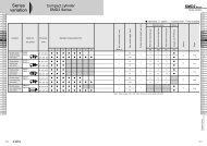
Side Channel Blowers Selections Guide<br />
Pressure<br />
0 mbar 50 mbar 75 mbar 100 mbar 125 mbar 150 mbar 175 mbar 200 mbar 225 mbar 250 mbar 300 mbar 350 mbar 400 mbar 450 mbar 500 mbar 550 mbar 600 mbar 700 mbar<br />
Model<br />
max. value<br />
m 3 /min m 3 /min kW m 3 /min kW m 3 /min kW m 3 /min kW m 3 /min kW m 3 /min kW m 3 /min kW m 3 /min kW m 3 /min kW m 3 /min kW m 3 /min kW m 3 /min kW m 3 /min kW m 3 /min kW m 3 /min kW m 3 /min kW m 3 /min kW<br />
RT-1xxx 0,8 0,38 0,20 60 mbar = 0.25 m 3 /min<br />
RT-2xxx 1,4 1,00 0,40 0,80 0,40 0,50 0,40 130 mbar = 0.22 m 3 /min<br />
RT-3xxx 2,4 1,90 0,75 1,65 0,75 1,40 0,75 1,20 0,75 0,90 0,90 0,65 0,90 0,35 1,30 200 mbar = 0.35 m 3 /min<br />
RT-4xxx 3,6 3,20 0,90 2,95 0,90 2,70 0,90 2,60 0,90 2,25 0,90 2,00 0,90 1,60 1,50 1,25 1,50 0,73 2,20 270 mbar = 0.35 m 3 /min<br />
RT-5xxx 5,2 4,95 2,20 4,40 2,20 4,30 2,20 3,85 2,20 3,75 2,20 3,20 2,20 3,10 2,20 2,50 2,20 230 mbar = 2.60 m 3 /min<br />
RT-6xxx 5,2 4,95 3,4t0 4,40 3,40 4,30 3,40 3,85 3,40 3,75 3,40 3,20 3,40 3,10 3,40 2,50 3,40 2,15 3,40 1,20 4,00 330 mbar = 0.75 m 3 /min<br />
RT-7xxx 9,2 8,40 5,50 8,00 5,50 7,75 5,50 7,30 5,50 6,90 5,50 6,20 5,50 5,92 5,50 5,45 5,50 4,95 5,50 4,00 5,50 300 mbar = 4.00 m 3 /min<br />
RT-8xxx 9,2 8,40 7,50 8,00 7,50 7,75 7,50 7,30 7,50 6,90 7,50 6,20 7,50 5,92 7,50 5,45 7,50 4,95 7,50 4,00 7,50 2,60 7,50 1,85 7,50 400 mbar = 1.80 m 3 /min<br />
RT-9xxx 18,9 18,00 9,00 17,50 9,00 17,00 9,00 16,70 9,00 16,00 9,00 15,30 9,00 14,50 9,00 14,00 13,00 12,60 13,00 9,70 13,00 8,50 20,00 6,60 20,00 5,00 20,00 450 mbar = 5.00 m 3 /min<br />
RT-23xxx 1,5 1,18 0,75 1,00 0,75 0,90 0,75 0,75 0,75 0,65 0,75 0,53 0,75 0,40 0,75 0,30 0,75 240 mbar = 0.16 m 3 /min<br />
RT-33xxx 2,6 2,20 1,75 2,10 1,75 1,95 1,75 1,80 1,75 1,68 1,75 1,45 1,75 1,30 1,75 1,20 1,75 1,05 1,75 0,75 1,75 0,60 2,20 375 mbar = 0.32 m 3 /min<br />
RT-43xxx 3,7 3,40 3,40 3,20 3,40 3,00 3,40 2,95 3,40 2,75 3,40 2,55 3,40 2,30 3,40 2,15 3,40 2,00 3,40 1,60 3,40 1,35 3,40 1,00 3,40 0,73 4,00 495 mbar = 0.60 m 3 /min<br />
RT-63xxx 5,2 4,80 4,00 4,70 4,00 4,55 4,00 4,40 4,00 4,30 4,00 4,20 4,00 4,00 4,00 3,75 4,00 3,65 4,00 3,30 4,00 3,05 4,00 2,60 5,50 2,20 5,50 1,80 5,50 1,45 7,50 580 mbar = 1.15 m 3 /min<br />
RT-83xxx 9,6 9,10 7,50 9,00 7,50 8,80 7,50 8,70 7,50 8,40 7,50 8,30 7,50 8,15 7,50 7,80 7,50 7,60 7,50 7,40 7,50 6,70 11,00 6,40 11,00 5,80 11,00 5,00 11,00 4,60 11,00 4,00 11,00 2,40 16,00 700 mbar = 2.40 m 3 /min<br />
Values at 50 Hz.<br />
Suction<br />
0 mbar -50 mbar -75 mbar -100 mbar -125 mbar -150 mbar -175 mbar -200 mbar -225 mbar -250 mbar -275 mbar -300 mbar -325 mbar -350 mbar -375 mbar -400 mbar -425 mbar -450 mbar<br />
Model<br />
max. value<br />
m 3 /min m 3 /min kW m 3 /min kW m 3 /min kW m 3 /min kW m 3 /min kW m 3 /min kW m 3 /min kW m 3 /min kW m 3 /min kW m 3 /min kW m 3 /min kW m 3 /min kW m 3 /min kW m 3 /min kW m 3 /min kW m 3 /min kW m 3 /min kW<br />
RT-1xxx 0,8 0,38 0,20 70 mbar = 0.18 m 3 /min<br />
RT-2xxx 1,4 0,98 0,40 0,72 0,40 0,41 0,40 110 mbar = 0.22 m 3 /min<br />
RT-3xxx 2,4 1,85 0,75 1,60 0,75 1,25 0,75 1,05 0,75 0,75 0,90 0,35 1,30 175 mbar = 0.35 m 3 /min<br />
RT-4xxx 3,6 3,00 0,90 2,70 0,90 2,20 0,90 1,80 0,90 1,50 1,30 1,25 1,30 0,80 1,50 220 mbar = 0.45 m 3 /min<br />
RT-5xxx 5,2 4,25 2,20 3,70 2,20 3,30 2,20 2,90 2,20 2,30 2,20 1,80 2,20 1,55 2,20 1,25 2,20 230 mbar = 1.20 m 3 /min<br />
RT-6xxx 5,2 4,25 3,40 3,70 3,40 3,30 3,40 2,90 3,40 2,30 3,40 1,80 3,40 1,55 3,40 1,25 3,40 1,00 3,40 270 mbar = 0.45 m 3 /min<br />
RT-7xxx 9,2 8,30 5,50 8,00 5,50 6,50 5,50 5,80 5,50 5,30 5,50 4,50 5,50 4,00 5,50 3,20 5,50 2,80 5,50 270 mbar = 2.00 m 3 /min<br />
RT-8xxx 9,2 8,30 7,50 8,00 7,50 6,50 7,50 5,80 7,50 5,30 7,50 4,50 7,50 4,00 7,50 3,20 7,50 2,80 7,50 2,10 7,50 1,50 7,50 300 mbar = 1.50 m 3 /min<br />
RT-9xxx 18,9 18,00 9,00 17,10 9,00 16,50 9,00 15,80 9,00 14,80 9,00 14,10 9,00 12,50 9,00 11,70 13,00 10,50 13,00 8,50 13,00 6,80 13,00 5,20 20,00 3,20 20,00 350 mbar = 3.20 m 3 /min<br />
RT-23xxx 1,5 1,25 0,75 1,10 0,75 0,90 0,75 0,80 0,75 0,70 0,75 0,45 0,75 0,25 0,75 200 mbar = 0.25 m 3 /min<br />
RT-33xxx 2,6 2,20 1,75 2,00 1,75 1,85 1,75 1,65 1,75 1,50 1,75 1,35 1,75 1,20 1,75 1,05 1,75 0,68 1,75 0,45 1,75 280 mbar = 0.25 m 3 /min<br />
RT-43xxx 3,7 3,40 3,40 3,05 3,40 2,70 3,40 2,60 3,40 2,40 3,40 2,20 3,40 2,00 3,40 1,75 3,40 1,60 3,40 1,20 3,40 0,90 3,40 0,70 3,40 0,50 4,00 355 mbar = 0.40 m 3 /min<br />
RT-63xxx 5,2 4,70 4,00 4,40 4,00 4,20 4,00 3,75 4,00 3,55 4,00 3,30 4,00 3,05 4,00 2,80 4,00 2,50 4,00 2,30 4,00 2,00 4,00 1,80 4,00 1,50 4,00 1,30 5,50 1,15 5,50 420 mbar = 0.80 m 3 /min<br />
RT-83xxx 9,6 8,80 7,50 8,60 7,50 8,30 7,50 8,15 7,50 7,80 7,50 7,60 7,50 7,20 7,50 6,80 7,50 6,70 7,50 6,40 7,50 6,00 7,50 5,70 11,00 5,00 11,00 4,90 11,00 2,30 11,00 1,60 11,00 1,20 16,00 450 mbar = 1.20 m 3 /min<br />
Values at 50 Hz.<br />
29<br />
All designs, dimensions <strong>and</strong> specifications are subject to change without notice (December 2008).<br />
www.bibus.ch
SUBMERSIBLE PUMPS<br />
BPS series 33<br />
TPS / TPV series 34<br />
RV series 35<br />
SV / BAV series 36<br />
KS / KSH series 38<br />
DS / DSK series 40<br />
JK series 41<br />
JKH series 42<br />
JKCH series 43<br />
SB series 44<br />
SW series 45<br />
Other pumps 46<br />
Applications<br />
31<br />
Cleaning <strong>and</strong> pumping down of liquids of<br />
Water <strong>and</strong> waste water tanks<br />
Fish tanks, Mines, pools <strong>and</strong> ponds<br />
Garden irrigation<br />
Reutilisation of process water<br />
Waterfalls in gardens, fountains<br />
Application at homes<br />
Septic tanks <strong>and</strong> water transport<br />
Pumping down of waste water<br />
Home drainages <strong>and</strong> dewatering<br />
Pumping down of ground water <strong>and</strong> level regulation<br />
Applications at house building <strong>and</strong> construction<br />
Agricultural applications<br />
Irrigation/Dewatering <strong>and</strong> <strong>industrial</strong> applications<br />
Advantages<br />
• Great diversification<br />
• Wide fulfilment of dem<strong>and</strong><br />
• High efficiency<br />
• Permanent further development
SUBMERSIBLE PUMPS<br />
Operating principle<br />
Submersible pumps are very effective.<br />
A wheel turns in a housing. The turning turbine sucks in the<br />
liquid through the inlet opening. The rotation accelerates<br />
the liquid <strong>and</strong> pushes it radial outside. The liquid flows out<br />
of the housing through the outlet opening.<br />
The most important parameters of a pump are revolution<br />
<strong>and</strong> wheel diameter.<br />
Due to the hydrodynamic operation method, both determine<br />
the attained pressure head <strong>and</strong> delivery rate significant.<br />
Using the full capacity of the pumps the cross sections of<br />
pump <strong>and</strong> hose have to be aligned. A reduction in hose<br />
cross section reduces pumping capacity <strong>and</strong> stresses the<br />
turning parts since the pump must now work against increased<br />
pressure in the system.<br />
Submersible pumps uses the pumped liquid also as a coolant.<br />
To prevent overheating our pumps include a protection<br />
against running dry - the so-called floater circuit.<br />
When the water level sinks, the floater circuit automatically<br />
switches off the pump. The latest generation of the SM<br />
series is now equipped with an integrated chip which regulates<br />
continuous monitoring electronically <strong>and</strong> turns the<br />
pump on or off, as necessary.<br />
Our pumps are operated with 230 V.<br />
Other models on request<br />
You can’t find the right submersible pump for<br />
your application?<br />
Please contact our technical support. We will<br />
be glad to help you.<br />
32<br />
Example of use<br />
Drainage or rain water use<br />
Water is collected from sealed surfaces<br />
(roof, terrace, parking space,<br />
etc.) <strong>and</strong> purified via a pre-filter for later<br />
use in the household as water for<br />
domestic use. Afterward, it is stored in<br />
a cement cistern. The water can then<br />
be removed, for example with a submersible<br />
pump, when needed.<br />
All designs, dimensions <strong>and</strong> specifications are subject to change without notice (December 2008).<br />
www.bibus.ch
BPS series<br />
BPS-200M / BPS-200MA<br />
BPS-300 / BPS-400<br />
Product characteristics<br />
• Built-in thermal protection switch<br />
• High quality plastic housing for long-term outdoor use<br />
• High efficiency motor with F class insulation <strong>and</strong> IP68<br />
• BPS-200 is optional available for sea water use<br />
• Optional with vertical switch<br />
Technical data<br />
Motor power<br />
Pump power<br />
Model<br />
Voltage<br />
Power<br />
Revolution<br />
Rated<br />
Maximum<br />
Outlet<br />
Dimensions<br />
L x W x H<br />
St<strong>and</strong>ard<br />
cable length<br />
Weight<br />
V, Hz W min -1 H (m) l/min H (m) l/min mm Inch mm m kg<br />
BPS-200M 230, 50/60 200 2900/3500 4 80 7 160 32 1¼ 190 x 155 x 290 10 3.8<br />
BPS-200MA 230, 50/60 200 2900/3500 4 80 7 160 32 1¼ 190 x 155 x 290 10 3.8<br />
BPS-300 230, 50/60 300 2900/3500 5 80 8 180 40 1½ 196 x 160 x 370 10 6.6<br />
BPS-400 230, 50/60 400 2900/3500 6 120 9 240 50 2 196 x 160 x 370 10 7.6<br />
33<br />
Performance data<br />
BPS-400<br />
BPS-300<br />
BPS-200M /<br />
BPS-200MA<br />
0 10 20 30 40 50 60 70 80 90 100 110 120 130 140 150 160 170 180 190 200 210 220<br />
m<br />
9<br />
8<br />
7<br />
6<br />
5<br />
4<br />
3<br />
2<br />
1<br />
l/min<br />
All designs, dimensions <strong>and</strong> specifications are subject to change without notice (December 2008).<br />
www.bibus.ch
TPS / TPV series<br />
TPS-50 / TPS-200 / TPV-200<br />
Product characteristics<br />
• Low axial <strong>and</strong> radial load design<br />
• Designed for 24 hours operation<br />
• Can pass solids from 4 mm (TPS) up to 20 mm (TPV)<br />
• Optional for light acid, alkali <strong>and</strong> seawater use<br />
Technical data<br />
Motor power<br />
Pump power<br />
Model<br />
Voltage<br />
Power<br />
Revolution<br />
Rated<br />
Maximum<br />
Outlet<br />
Dimensions<br />
L x W x H<br />
St<strong>and</strong>ard<br />
cable length<br />
Weight<br />
34<br />
V, Hz W min -1 H (m) l/min H (m) l/min mm Inch mm m kg<br />
TPS-50 230, 50/60 80 2900/3500 3 22 4 40 20 ¾ 114 x 114 x 265 10 2.5<br />
TPS-200 230, 50/60 200 2900/3500 4 120 7 140 32 1½ 168 x 146 x 288 10 3.6<br />
TPV-200 230, 50/60 200 2900/3500 4 120 7 140 32 1½ 168 x 146 x 288 10 3.6<br />
Performance data<br />
TPV-200 /<br />
TPS-200<br />
TPS-50<br />
m<br />
9<br />
8<br />
7<br />
6<br />
5<br />
4<br />
3<br />
2<br />
1<br />
0 10 20 30 40 50 60 70 80 90 100 110 120 130 140 150 l/min<br />
All designs, dimensions <strong>and</strong> specifications are subject to change without notice (December 2008).<br />
www.bibus.ch
RV series<br />
RV-32 / RV-40<br />
Product characteristics<br />
• Innovative sewage pump with robust plastic housing<br />
• Designed to run continuously without stop for long time<br />
• Can pass solid up to 18 mm<br />
• Double volute chamber to barricade dirty stuff<br />
Technical data<br />
Motor power<br />
Pump power<br />
Model<br />
Voltage<br />
Power<br />
Revolution<br />
Rated<br />
Maximum<br />
Outlet<br />
Dimensions<br />
L x W x H<br />
St<strong>and</strong>ard<br />
cable length<br />
Weight<br />
V, Hz W min -1 H (m) l/min H (m) l/min mm Inch mm m kg<br />
RV-32 230, 50/60 200 2900/3500 4 80 6 130 32 1¼ 154 x 143 x 345 10 3.9<br />
RV-40 230, 50/60 250 2900/3500 5 120 8 170 32 1¼ 154 x 143 x 345 10 5.9<br />
35<br />
Performance data<br />
RV-40<br />
RV-32<br />
m<br />
8<br />
7<br />
6<br />
5<br />
4<br />
3<br />
2<br />
1<br />
0 20 40 60 80 100 120 140 160 180 l/min<br />
All designs, dimensions <strong>and</strong> specifications are subject to change without notice (December 2008).<br />
www.bibus.ch
SV series<br />
SV-150 / SV-250 / SV-400<br />
SV-550 / SV-750<br />
Product characteristics<br />
• Can pass solid from 20 up to 40 mm<br />
• Waste water applications possible<br />
• Non-clogging design<br />
• Built-in thermal protection switch<br />
• Stainless steel motor housing<br />
Technical data<br />
Motor power<br />
Pump power<br />
Model<br />
Voltage<br />
Power<br />
Revolution<br />
Rated<br />
Maximum<br />
Outlet<br />
Dimensions<br />
L x W x H<br />
St<strong>and</strong>ard<br />
cable length<br />
Weight<br />
36<br />
V, Hz W min -1 H (m) l/min H (m) l/min mm Inch mm m kg<br />
SV-150 230, 50/60 150 2900/3500 4 100 5.7 170 40 1½ 415 x 155 x 210 10 8<br />
SV-250 230, 50/60 250 2900/3500 4.5 120 7.5 220 40 1½ 415 x 155 x 210 10 9.5<br />
SV-400 230, 50/60 400 2900/3500 6 180 10 300 50 2 435 x 155 x 240 10 12<br />
SV-550 230, 50/60 550 2900/3500 8 220 10 360 80 3 435 x 155 x 260 10 14<br />
SV-750 230, 50/60 750 2900/3500 9 230 11 380 80 3 435 x 155 x 260 10 18<br />
Performance data<br />
m<br />
SV-750<br />
SV-550<br />
SV-400<br />
SV-250<br />
SV-150<br />
12<br />
10<br />
8<br />
6<br />
4<br />
2<br />
0 50 100 150 200 250 300 350 400 l/min<br />
All designs, dimensions <strong>and</strong> specifications are subject to change without notice (December 2008).<br />
www.bibus.ch
BAV series<br />
BAV-150 / BAV-250 / BAV-400 /<br />
BAV-550<br />
Product characteristics<br />
• Non-clogging vortex impeller<br />
• Built-in thermal protection switch<br />
• Stainless steel motor housing<br />
• Passes solid diameter from 10 up to 35 mm<br />
• Optional with strainer for clean water<br />
Technical data<br />
Motor power<br />
Pump power<br />
Model<br />
Voltage<br />
Power<br />
Revolution<br />
Rated<br />
Maximum<br />
Outlet<br />
Dimensions<br />
L x W x H<br />
St<strong>and</strong>ard<br />
cable length<br />
Weight<br />
V, Hz W min -1 H (m) l/min H (m) l/min mm Inch mm m kg<br />
BAV-150 230, 50/60 150 2900/3500 3.5 60 7 130 32 1¼ 190 x 140 x 300 10 5<br />
BAV-250 230, 50/60 250 2900/3500 5 120 8 200 40 1½ 200 x 140 x 320 10 6<br />
BAV-400 230, 50/60 400 2900/3500 5 180 10 280 50 2 230 x 160 x 350 10 6.5<br />
BAV-550 230, 50/60 550 2900/3500 6 200 11 340 50 2 230 x 160 x 380 10 10<br />
37<br />
Performance data<br />
BAV-550<br />
BAV-400<br />
BAV-250<br />
BAV-150<br />
m<br />
11<br />
10<br />
9<br />
8<br />
7<br />
6<br />
5<br />
4<br />
3<br />
2<br />
1<br />
0 50 100 150 200 250 300 350 l/min<br />
All designs, dimensions <strong>and</strong> specifications are subject to change without notice (December 2008).<br />
www.bibus.ch
KS series<br />
KS-03 / KS-04 / KS-05 / KS-08 / KS-20 /<br />
KS-30 / KS-50 / KS-75 / KS-100<br />
Product characteristics<br />
• Motor with IP68 protection <strong>and</strong> F class insulation<br />
• Low temperature rise for long service life<br />
• Built-in thermal protection switch<br />
• Optional with double mechanical seal (up from KS-08)<br />
Technical data<br />
Motor power<br />
Pump power<br />
Model<br />
Voltage<br />
Power<br />
Revolution<br />
Rated<br />
Maximum<br />
Outlet<br />
Dimensions<br />
L x W x H<br />
St<strong>and</strong>ard<br />
cable length<br />
Weight<br />
38<br />
V, Hz W min -1 H (m) l/min H (m) l/min mm Inch mm m kg<br />
KS-03 230, 50/60 250 2900/3500 3 130 8 180 40 1½ 188 x 141 x 305 10 9<br />
KS-04 230, 50/60 400 2900/3500 5 150 8 220 50 2 208 x 140 x 359 10 11<br />
KS-05 230, 50/60 400 2900/3500 5 160 10 260 50 2 230 x 156 x 375 10 14<br />
KS-08 230, 50/60 750 2900/3500 6 240 13 380 50(80) 2 (3) 290 x 180 x 425 10 21<br />
KS-20 230 1 , 50/60 1500 2900/3500 10 300 16 600 80 3 278 x 182 x 475 10 31<br />
KS-30 380, 50/60 2200 2900/3500 10 500 18 800 80 3 390 x 250 x 450 10 42<br />
KS-50 380, 50/60 3700 2900/3500 10 800 21 1100 100 4 450 x 240 x 530 10 48<br />
KS-75 380, 50/60 5600 2900/3500 15 800 23 1300 100 4 550 x 310 x 590 10 60<br />
KS-100 380, 50/60 7500 2900/3500 18 900 26 1600 150 6 550 x 310 x 610 10 70<br />
1)<br />
also available as 380 V version<br />
Performance data<br />
KS-100<br />
KS-75<br />
KS-50<br />
KS-30<br />
KS-20<br />
KS-08<br />
KS-05<br />
KS-04<br />
KS-03<br />
m<br />
30<br />
25<br />
20<br />
15<br />
10<br />
5<br />
0 150 300 450 600 750 900 1050 1200 1350 1500 1650 l/min<br />
All designs, dimensions <strong>and</strong> specifications are subject to change without notice (December 2008).<br />
www.bibus.ch
KSH series<br />
KSH-05 / KSH-10 / KSH-20<br />
KSH-30 / KSH-50<br />
Product characteristics<br />
• Motor with IP68 protection <strong>and</strong> F class insulation<br />
• Low temperature rise for long service life<br />
• Built-in thermal protection switch<br />
• With double mechanical seal<br />
Technical data<br />
Motor power<br />
Pump power<br />
Model<br />
Voltage<br />
Power<br />
Revolution<br />
Rated<br />
Maximum<br />
Outlet<br />
Dimensions<br />
L x W x H<br />
St<strong>and</strong>ard<br />
cable length<br />
Weight<br />
V, Hz W min -1 H (m) l/min H (m) l/min mm Inch mm m kg<br />
KSH-05 230, 50/60 400 2900/3500 10 80 18 120 40 1½ 290 x 168 x 422 10 16<br />
KSH-10 230, 50/60 750 2900/3500 15 100 21 200 40 1½ 283 x 227 x 465 10 29<br />
KSH-20 230 1 , 50/60 1500 2900/3500 15 180 25 320 50 2 283 x 227 x 484 10 32<br />
KSH-30 380, 50/60 2200 2900/3500 18 250 30 420 50 2 395 x 250 x 510 10 42<br />
39<br />
KSH-50 380, 50/60 3700 2900/3500 20 300 35 550 80 3 455 x 290 x 585 10 50<br />
1)<br />
also available as 380 V version<br />
Performance data<br />
m<br />
KSH-50<br />
KSH-30<br />
KSH-20<br />
KSH-10<br />
KSH-05<br />
40<br />
35<br />
30<br />
25<br />
20<br />
15<br />
10<br />
5<br />
0 50 100 150 200 250 300 350 400 450 500 550 600 l/min<br />
All designs, dimensions <strong>and</strong> specifications are subject to change without notice (December 2008).<br />
www.bibus.ch
DS / DSK series<br />
DS-05 / DS-20 / DS-30 / DS-50 /<br />
DS-100 / DSK-05 / DSK-10 / DSK-20 /<br />
DSK-30 / DSK-50<br />
Product characteristics<br />
• Motor with IP68 protection <strong>and</strong> F class insulation<br />
• Low temperature rise for long service life<br />
• Built-in thermal protection switch<br />
• Stainless steel motor housing<br />
• Optional pedestal for easy installation (TDS / TDSK)<br />
Technical data<br />
Motor power<br />
Pump power<br />
Model<br />
Voltage<br />
Power<br />
Revolution<br />
Rated<br />
Maximum<br />
Outlet<br />
Dimensions<br />
L x W x H<br />
St<strong>and</strong>ard<br />
cable length<br />
Weight<br />
40<br />
V, Hz W min -1 H (m) l/min H (m) l/min mm Inch mm m kg<br />
DS-05 230, 50/60 400 2900/3500 5 160 10 240 50 2 245 x 188 x 420 10 18<br />
DS-20 230 1 , 50/60 1500 2900/3500 8 380 15 650 80 3 285 x 223 x 550 10 32<br />
DS-30 380, 50/60 2200 2900/3500 10 550 18 1060 80 3 410 x 240 x 520 10 42<br />
DS-50 380, 50/60 3700 2900/3500 12 600 19 1210 100 4 480 x 250 x 550 10 57<br />
DS-100 380, 50/60 7500 2900/3500 15 1100 26 1500 100 4 530 x 320 x 610 10 75<br />
DSK-05 230, 50/60 400 2900/3500 5 100 8 240 50 2 245 x 188 x 420 10 18<br />
DSK-10 230, 50/60 750 2900/3500 6 250 12 350 50 2 280 x 195 x 420 10 30<br />
DSK-20 230 1 , 50/60 1500 2900/3500 8 500 15 650 80 3 280 x 195 x 425 10 35<br />
DSK-30 380, 50/60 2200 2900/3500 10 550 18 800 80 3 410 x 240 x 520 10 46<br />
DSK-50 380, 50/60 3700 2900/3500 12 700 21 1200 100 4 480 x 250 x 550 10 62<br />
1)<br />
also available as 380 V version<br />
Performance data<br />
DS-100<br />
DS-50<br />
DSK-50<br />
DSK-30<br />
DS-30<br />
DS-20<br />
DSK-20<br />
DSK-10<br />
DSK-05<br />
DS-05<br />
m<br />
30<br />
25<br />
20<br />
15<br />
10<br />
5<br />
0 150 300 450 600 750 900 1050 1200 1350 1500 l/min<br />
All designs, dimensions <strong>and</strong> specifications are subject to change without notice (December 2008).<br />
www.bibus.ch
JK series<br />
JK-05 / JK-10 / JK-20<br />
JK-30 / JK-50 / JK 75<br />
Product characteristics<br />
• Non-clogging impeller design for superior operation<br />
• Optional strainer may protect oil seal to prolong life<br />
• Built-in thermal protection switch<br />
• Optional silicon carbide mechanical seal <strong>and</strong> Tungsten<br />
impeller<br />
• Optional pedestal for easy installation (TJK)<br />
Technical data<br />
Motor power<br />
Pump power<br />
Model<br />
Voltage<br />
Power<br />
Revolution<br />
Rated<br />
Maximum<br />
Outlet<br />
Dimensions<br />
L x W x H<br />
St<strong>and</strong>ard<br />
cable length<br />
Weight<br />
V, Hz W min -1 H (m) l/min H (m) l/min mm Inch mm m kg<br />
JK-05 230, 50/60 400 2900/3500 6 150 9 300 50 2 223 x 132 x 395 10 14<br />
JK-10 230, 50/60 750 2900/3500 9 200 12 420 50 2 223 x 132 x 425 10 30<br />
JK-20 230 1 , 50/60 1500 2900/3500 12 300 17 620 80 3 390 x 210 x 530 10 32.2<br />
JK-30 380, 50/60 2200 2900/3500 14 320 20 750 80 3 392 x 210 x 550 10 34.5<br />
JK-50 380, 50/60 3700 2900/3500 15 480 23 1100 100 4 525 x 250 x 635 10 45<br />
JK-75 380, 50/60 5500 2900/3500 18 600 25 1350 100 4 525 x 250 x 675 10 54<br />
1)<br />
also available as 380 V version<br />
41<br />
Performance data<br />
JK-75<br />
JK-50<br />
JK-30<br />
JK-20<br />
JK-10<br />
JK-05<br />
m<br />
25<br />
20<br />
15<br />
10<br />
5<br />
0 150 300 450 600 750 900 1050 1200 1350 l/min<br />
All designs, dimensions <strong>and</strong> specifications are subject to change without notice (December 2008).<br />
www.bibus.ch
JKH series<br />
JKH-150 / JKH-250<br />
JKH-400 / JKH-750<br />
Product characteristics<br />
• Spherical clearance up to 35 mm<br />
Technical data<br />
Motor power<br />
Pump power<br />
Model<br />
Voltage<br />
Power<br />
Revolution<br />
Rated<br />
Maximum<br />
Outlet<br />
Dimensions<br />
L x W x H<br />
St<strong>and</strong>ard<br />
cable length<br />
Weight<br />
42<br />
V, Hz W min -1 H (m) l/min H (m) l/min mm Inch mm m kg<br />
JKH-150 230, 50/60 150 2900/3500 4 100 6 160 50 2 305 x 152 x 175 10 5,5<br />
JKH-250 230, 50/60 250 2900/3500 5 120 7 220 50 2 320 x 152 x 175 10 6,5<br />
JKH-400 230, 50/60 400 2900/3500 6 180 10 300 50 2 330 x 162 x 180 10 8<br />
JKH-750 230, 50/60 750 2900/3500 8 220 12 450 50 2 350 x 162 x 180 10 11<br />
Performance data<br />
m<br />
JKH-750<br />
JKH-400<br />
JKH-150<br />
JKH-150<br />
12<br />
10<br />
8<br />
6<br />
4<br />
2<br />
0 50 100 150 200 250 300 350 400 450 500 l/min<br />
All designs, dimensions <strong>and</strong> specifications are subject to change without notice (December 2008).<br />
www.bibus.ch
JKCH series<br />
JKCH-30 / JKCH-40 / JKCH-50<br />
Product characteristics<br />
• Stainless steel housing<br />
• Impellers. diffusers <strong>and</strong> separators in PPO material <strong>and</strong><br />
fiber glass<br />
• Built-in thermal protection switch<br />
• Particularly suited for dewatering, irrigation <strong>and</strong> water<br />
boosting from 30 to 60 m head<br />
Technical data<br />
Motor power<br />
Pump power<br />
Model<br />
Voltage<br />
Power<br />
Revolution<br />
Rated<br />
Maximum<br />
Outlet<br />
Dimensions<br />
L x W x H<br />
St<strong>and</strong>ard<br />
cable length<br />
Weight<br />
V, Hz W min -1 H (m) l/min H (m) l/min mm Inch mm m kg<br />
JKCH-30 230, 50/60 800 2900/3500 20 45 31 100 32 1¼ 126 x 126 x 454 10 12.8<br />
JKCH-40 230, 50/60 900 2900/3500 25 55 42 100 32 1¼ 126 x 126 x 478 10 13.8<br />
JKCH-50 230, 50/60 1100 2900/3500 30 58 52 100 32 1¼ 126 x 126 x 530 10 14.8<br />
43<br />
Performance data<br />
m<br />
60<br />
JKCH-50<br />
JKCH-40<br />
JKCH-30<br />
50<br />
40<br />
30<br />
20<br />
10<br />
0 10 20 30 40 50 60 70 80 90 100 l/min<br />
All designs, dimensions <strong>and</strong> specifications are subject to change without notice (December 2008).<br />
www.bibus.ch
SB series<br />
SB-05 / SB-10 / SB-20<br />
SB-30 / SB-50 / SB-75<br />
Product characteristics<br />
• Non-clogging impeller design for superior operation<br />
• Optional strainer may protect oil seal to prolong life<br />
• Stainless steel for use with sea water <strong>and</strong> light acid<br />
• Built-in thermal protection switch<br />
• Optional silicon carbide mechanical seal <strong>and</strong> Tungsten<br />
impeller<br />
Technical data<br />
Motor power<br />
Pump power<br />
Model<br />
Voltage<br />
Power<br />
Revolution<br />
Rated<br />
Maximum<br />
Outlet<br />
Dimensions<br />
L x W x H<br />
St<strong>and</strong>ard<br />
cable length<br />
Weight<br />
44<br />
V, Hz W min -1 H (m) l/min H (m) l/min mm Inch mm m kg<br />
SB-05 230, 50/60 400 2900/3500 6 150 9 300 50 2 223 x 132 x 395 10 14<br />
SB-10 230, 50/60 750 2900/3500 9 200 12 420 50 2 223 x 132 x 425 10 21<br />
SB-20 230 1 , 50/60 1500 2900/3500 12 300 17 620 80 3 390 x 210 x 530 10 32.2<br />
SB-30 230 1 , 50/60 2200 2900/3500 14 320 20 750 80 3 392 x 210 x 550 10 34.5<br />
SB-50 230 1 , 50/60 3700 2900/3500 15 480 23 1100 80 (100) 3 (4) 525 x 250 x 635 10 45<br />
SB-75 380, 50/60 5500 2900/3500 18 600 25 1350 100 4 525 x 250 x 675 10 54<br />
1)<br />
also available as 380 V version<br />
Performance data<br />
SB-75<br />
SB-50<br />
SB-30<br />
SB-20<br />
SB-10<br />
SB-05<br />
m<br />
25<br />
20<br />
15<br />
10<br />
5<br />
0 150 300 450 600 750 900 1050 1200 1350 l/min<br />
All designs, dimensions <strong>and</strong> specifications are subject to change without notice (December 2008).<br />
www.bibus.ch
SW series<br />
SW-50 / SW-100 / SW-200<br />
Product characteristics<br />
• Two pole high efficient motor<br />
• Stainless steel pump casing with tough fiber glass plastic<br />
impeller <strong>and</strong> diffuser<br />
• Lightweight aluminum motor housing for superior heat<br />
transfer<br />
Technical data<br />
Motor power<br />
Pump power<br />
Model<br />
Voltage<br />
Power<br />
Revolution<br />
Rated<br />
Maximum<br />
Outlet<br />
Dimensions<br />
L x W x H<br />
St<strong>and</strong>ard<br />
cable length<br />
Weight<br />
V, Hz W min -1 H (m) l/min H (m) l/min mm Inch mm m kg<br />
SW-50 230, 50/60 400 2700/3450 10 70 18 120 25 1 340 x 200 x 160 10 10<br />
SW-100 230, 50/60 750 2700/3450 13 120 20 200 40 1½ 400 x 220 x 220 10 18<br />
SW-200 230 1 , 50/60 1500 2700/3450 16 250 20 400 50 2 354 x 182 x 220 10 20<br />
1)<br />
also available as 380 V version<br />
45<br />
Performance data<br />
m<br />
25<br />
SW-200<br />
SW-100<br />
SW-50<br />
20<br />
15<br />
10<br />
5<br />
0 100 200 300 400 500 600 l/min<br />
All designs, dimensions <strong>and</strong> specifications are subject to change without notice (December 2008).<br />
www.bibus.ch
BAS series<br />
m<br />
10<br />
9<br />
8<br />
7<br />
6<br />
5<br />
4<br />
3<br />
2<br />
1<br />
BAS-100 / BAS-200 / BAS-300 / BAS-400 / BAS-600<br />
BAS 100 BAS 200 BAS 300 BAS 400<br />
BAS 600<br />
m<br />
10<br />
9<br />
8<br />
7<br />
6<br />
5<br />
4<br />
3<br />
2<br />
1<br />
0 25 50 75 100 125 150 175 200 225 250 275 300 325 350 375<br />
SD / SS / SD-250 / SD-400 / SD-750 / SS-250 / SS-400 /<br />
SDP series SS-750 / SDP-400 / SDP-750<br />
m<br />
15<br />
12<br />
9<br />
6<br />
l/min<br />
m<br />
15<br />
12<br />
9<br />
6<br />
3<br />
SD-SS 250<br />
SDP/SD/SS-400<br />
SDP/SD/SS-750<br />
3<br />
0 20 40 60 80 100 120 140 160 180 200 220 240 260 280 300 320 340 360 380<br />
l/min<br />
46<br />
ADL series<br />
m<br />
22<br />
20<br />
18<br />
16<br />
14<br />
12<br />
10<br />
8<br />
6<br />
4<br />
2<br />
65ADL51.5 / 80ADL51.5 / 80ADL52.2 / 80ADL53.7<br />
65ADL51.5<br />
80ADL51.5<br />
80ADL53.7<br />
80ADL52.2<br />
m<br />
22<br />
20<br />
18<br />
16<br />
14<br />
12<br />
10<br />
8<br />
6<br />
4<br />
2<br />
0 200 400 600 800 1000 1200 1400<br />
l/min<br />
GC series GC-2051 / GC-2053 / GC-2061 / GC-2063 / GC-3053 /<br />
GC-3063 / GC-5053 / GC-5063 / GC-7553 / GC-7563<br />
m<br />
60<br />
54<br />
42<br />
36<br />
30<br />
24<br />
18<br />
12<br />
6<br />
GC-2051<br />
GC-2053<br />
GC-2061<br />
GC-2063<br />
GC-3053<br />
GC-3063<br />
GC-5053<br />
GC-5063<br />
GC-7553<br />
GC-7563<br />
0 100 200 300 400<br />
m<br />
60<br />
54<br />
42<br />
36<br />
30<br />
24<br />
18<br />
12<br />
6<br />
l/min<br />
All designs, dimensions <strong>and</strong> specifications are subject to change without notice (December 2008).<br />
www.bibus.ch
TM series TM-15H / TM-15L / TM-22H / TM-22L / TM-37H /<br />
TM-37M / TM-37L / TM-55H / TM-55L<br />
m<br />
35<br />
TM-37M<br />
30<br />
25<br />
TM-22H<br />
20<br />
TM-37H<br />
15<br />
10<br />
5<br />
TM-15L<br />
TM-22L<br />
TM-15H<br />
TM-55H<br />
TM-55L<br />
TM-37L<br />
0 250 500 750 1000 1250 1500<br />
m<br />
35<br />
30<br />
25<br />
20<br />
15<br />
10<br />
5<br />
l/min<br />
CP series 50 x 32-160 / 50 x 32-200 / 65 x 50-160 / 65 x 40-200 /<br />
65 x 40-250 / 80 x 65-160 / 80 x 50-200 / 80 x 50-250 /<br />
100 x 80-160 / 100 x 65-200 / 100 x 65-250 / 125 x 100-200<br />
m<br />
80<br />
65 x 40-250<br />
70<br />
80 x 50-250<br />
60<br />
50<br />
40<br />
30<br />
65 x 40-200 80 x 50-200<br />
50 x 32-200<br />
65 x 50-160<br />
20<br />
10<br />
50 x 32-160<br />
80 x 65-160<br />
100 x 65-250<br />
100 x 65-200<br />
100 x 80-160<br />
125 x 100-200<br />
m<br />
80<br />
70<br />
60<br />
50<br />
40<br />
30<br />
20<br />
10<br />
HC-40 series<br />
0 0.17 0.33 0.5 0.67 0.83 1 1.17 l/min<br />
HC-40<br />
m<br />
m<br />
70<br />
70<br />
60<br />
60<br />
50<br />
50<br />
40<br />
40<br />
30<br />
30<br />
20<br />
HC-40<br />
20<br />
10<br />
10<br />
47<br />
0 50 100 150 200 250<br />
l/min<br />
SJ series<br />
m<br />
48<br />
42<br />
36<br />
30<br />
24<br />
18<br />
12<br />
6<br />
SJ-05 / SJ-05E / SJ-10 / SJ-10E<br />
SJ-10 / SJ-10E<br />
SJ-05 / SJ-05E<br />
m<br />
48<br />
42<br />
36<br />
30<br />
24<br />
18<br />
12<br />
6<br />
0 8 16 24 32 40 48 56 64 72<br />
l/min<br />
All designs, dimensions <strong>and</strong> specifications are subject to change without notice (December 2008).<br />
www.bibus.ch
AIR OPERATED DIAPHRAGM PUMPS<br />
Y01.NDP.5 52<br />
Y01.DP.10 / Y01.NDP.10 54<br />
Y01.NDP.15 56<br />
Y01.NDP.20 58<br />
Y01.NDP.25 60<br />
Y01.NDP.40 62<br />
Y01.NDP.50 64<br />
Y01.NDP.80 66<br />
Applications<br />
Chemical industry<br />
Acids <strong>and</strong> alkalies<br />
Suspensions <strong>and</strong> solutions<br />
<strong>Environmental</strong> industry<br />
Waste water treatment<br />
Slurries<br />
Pharmaceutical industry <strong>and</strong> laboratory<br />
Alcohols, glycerin<br />
Blood plasma und sterile products<br />
Ointments <strong>and</strong> pastes<br />
Ceramics <strong>and</strong> porcelain industry<br />
abrasive applications<br />
Food <strong>and</strong> beverage industry<br />
Food processing applications (FDA approved)<br />
Paper <strong>and</strong> print industry<br />
Printing inks <strong>and</strong> varnishes<br />
Solvents<br />
Dispersions <strong>and</strong> latex<br />
Petroleum industry<br />
Tank cleaning <strong>and</strong> waste oil<br />
Petroleum <strong>and</strong> fuels<br />
Tool <strong>and</strong> Dispenser Systems<br />
Lubrication<br />
Cooling<br />
Advantages<br />
• Extended performance diaphragm<br />
• Unrestricted usage of fluid<br />
• Excellent wear resistance<br />
• Simple <strong>and</strong> safe flow control<br />
• High energy efficiency<br />
• Air driven intrinsically safe (ATEX)<br />
• Non-lube air valve<br />
• Air valve for safe pump start<br />
• Dry start <strong>and</strong> self priming is possible<br />
49
AIR OPERATED DIAPHRAGM PUMPS<br />
Operating principle<br />
An air driven diaphragm pump will start working with compressed<br />
air at 1-7 bar (5 bar for plastic pumps). The compressed<br />
air will flow through a valve mechanism to the left<br />
or right air chamber.<br />
At the end of the stroke the air valve will switch over <strong>and</strong><br />
the whole process is reversed. If the liquid outlet of the<br />
pump is closed the pump will stop as the air <strong>and</strong> liquid<br />
pressures will be balanced. The diaphragm will have balanced<br />
air <strong>and</strong> liquid pressures on each side which gives a<br />
long diaphragm life.<br />
50<br />
The two air chambers are separated from the liquid chambers<br />
by two flexible diaphragms connected to each other<br />
by a centre rod. If the air valve is in a position to allow compressed<br />
air to flow into the right air chamber,<br />
the left air chamber will exhaust through a<br />
muffler. The air flow causes the centre rod to<br />
move to the right so the liquid chamber becomes<br />
smaller <strong>and</strong> the liquid is pushed through<br />
the valve in the top manifold. The liquid pressure<br />
also closes the valve to the right chamber.<br />
At the same time the left liquid chamber will get<br />
bigger <strong>and</strong> creates a vacuum so that the bottom<br />
valve opens <strong>and</strong> liquid is pulled into the<br />
left chamber.<br />
All designs, dimensions <strong>and</strong> specifications are subject to change without notice (December 2008).<br />
www.bibus.ch
AIR OPERATED DIAPHRAGM PUMPS<br />
Your advantages<br />
Extended performance diaphragm<br />
The pressure differences on the membrane surface <strong>and</strong> thus<br />
the applicable inner strain are very low in comparison to mechanically<br />
driven membrane pumps. The development of a<br />
new long-term membrane from a PTFE compound (PTFE foil<br />
with EPDM carrier material) allowed 3 properties to be combined<br />
at the same time:<br />
- Extremely long membrane service life<br />
- Diffusion density consistency<br />
- Better conductivity (to prevent static charging)<br />
Dry start <strong>and</strong> self priming<br />
Completely self priming from a dry start, with suction lifts<br />
not exceeding 5 meter on fresh water. The dry running capability<br />
enables safe installations to be made where the liquid<br />
supply is likely to be made intermittent. If source runs<br />
dry, the pump continuous to operate without damage by<br />
overheating or friction wear until further liquid is available.<br />
Simple <strong>and</strong> safe flow control<br />
Infinitely variable flow control can be simply by opening<br />
or closing a valve on the discharge, or by increasing or<br />
decreasing the air supply.<br />
Air driven intrinsically safe (ATEX)<br />
The power source of compressed air is most suitable for<br />
operation in potentially explosive environments. The pneumatic<br />
drive absolutely spark-free <strong>and</strong> in order to prevent<br />
possible static charging, conductive metal housings or<br />
PVDF ones enriched with graphite are available.<br />
Unrestricted use of fluids<br />
Practically any fluid can be pumped, from clear water to<br />
low-boiling-point media to highly viscous fluids <strong>and</strong> chemically<br />
aggressive media. The valves can h<strong>and</strong>le polluted fluids<br />
<strong>and</strong> solids without impairing vacuum capacity. The slow<br />
speed of the current flow <strong>and</strong> the gentle-action pumping<br />
make it easy to also pump abrasive <strong>and</strong> erosive media.<br />
51<br />
All designs, dimensions <strong>and</strong> specifications are subject to change without notice (December 2008).<br />
www.bibus.ch
Y01.NDP.5<br />
Size 1/4"<br />
Max. discharge volume 10 l/min<br />
Technical data<br />
Specifications<br />
Port dimensions<br />
1/4“ (6mm)<br />
Pump type<br />
P V A S<br />
Material inlet • • 1/4“ BSP<br />
• • 1/4“ BSPT<br />
Material outlet • • 1/4“ BSP<br />
• • 1/4“ BSPT<br />
Air inlet • • • • 1/4“ BSPT (with ball valve)<br />
Exhaust • • • • Rc 3/8“ (with silencer)<br />
Discharge volume<br />
per cycle<br />
Rubber diaphragm<br />
n/a<br />
PTFE diaphragm • • • • 13-20 cm³<br />
Air pressure range • • • • 2–7 bar<br />
Max. discharge pressure • • • • 7 bar<br />
Maximum size of solid • • • • less than Ø 0.2 mm<br />
Weight in kg 1.4 1.45 1.5 3.0<br />
52<br />
Wetted materials<br />
P A S V<br />
Diaphragm<br />
Polypropylene<br />
(PPG)<br />
Aluminium<br />
(AC4C-T6)<br />
Stainless steel<br />
(SUS 316)<br />
Kynar ®<br />
(PVDF)<br />
T<br />
Teflon ®<br />
(PTFE)<br />
Y01.NDP.5.FPT Y01.NDP.5.FAT Y01.NDP.5.FST Y01.NDP.5.FVT<br />
All designs, dimensions <strong>and</strong> specifications are subject to change without notice (December 2008).<br />
www.bibus.ch
Dimensions<br />
Y01.NDP.5.FAT<br />
Performance data<br />
Y01.NDP.5.FAT<br />
m<br />
80<br />
70<br />
60<br />
50<br />
40<br />
30<br />
7 bar<br />
100 l/min<br />
6 bar<br />
5 bar<br />
4 bar 50 l/min<br />
3 bar<br />
150 l/min<br />
200 l/min<br />
20<br />
2 bar<br />
10<br />
0<br />
0 2 4 6 8 10 12 l/min<br />
Y01.NDP.5.FST<br />
Y01.NDP.5.FST<br />
m<br />
80<br />
70<br />
60<br />
50<br />
40<br />
30<br />
7 bar<br />
100 l/min<br />
6 bar<br />
5 bar<br />
4 bar 50 l/min<br />
3 bar<br />
150 l/min<br />
200 l/min<br />
20<br />
2 bar<br />
10<br />
0<br />
0 2 4 6 8 10 12 l/min<br />
Y01.NDP.5.FPT<br />
Y01.NDP.5.FPT<br />
m<br />
80<br />
70<br />
60<br />
50<br />
40<br />
30<br />
7 bar<br />
100 l/min<br />
6 bar<br />
5 bar<br />
4 bar 50 l/min<br />
3 bar<br />
150 l/min<br />
200 l/min<br />
20<br />
2 bar<br />
10<br />
Y01.NDP.5.FVT<br />
0<br />
0 2 4 6 8 10 12 l/min<br />
Y01.NDP.5.FVT<br />
m<br />
80<br />
53<br />
70<br />
60<br />
50<br />
40<br />
30<br />
7 bar<br />
100 l/min<br />
6 bar<br />
5 bar<br />
4 bar 50 l/min<br />
3 bar<br />
150 l/min<br />
200 l/min<br />
20<br />
2 bar<br />
10<br />
0<br />
0 2 4 6 8 10 12 l/min<br />
All designs, dimensions <strong>and</strong> specifications are subject to change without notice (December 2008).<br />
www.bibus.ch
Y01.NDP.10<br />
Y01.DP.10<br />
Size 3/8"<br />
Max. discharge volume 20 l/min<br />
Technical data<br />
Pump type P<br />
T P<br />
A S<br />
Specifications<br />
(DP)<br />
(NDP) (NDP)<br />
Port dimensions<br />
Material inlet • • 3/8“ BSP<br />
3/8“ (10mm)<br />
• • 3/8“ BSPT<br />
Material outlet • • • 3/8“ BSP<br />
• • 3/8“ BSPT<br />
Air inlet • • • • • 1/4“ BSPT (with ball valve)<br />
Exhaust • • • • • Rc 3/8“ (with silencer)<br />
Discharge volume<br />
Rubber diaphragm • • • • • 52 cm³<br />
per cycle<br />
PTFE diaphragm • • • • • 52 cm³<br />
Air pressure range • 2–5 bar<br />
Air pressure range • • • • 2–7 bar<br />
Max. discharge pressure • 5 bar<br />
• • • • 7 bar<br />
Maximum size of solid • • • • • less than Ø 1.0 mm<br />
Weight in kg 3.3 4.6 5.3 6.0 3.1<br />
54<br />
Wetted materials P (DP) A 1) S T (NDP) P (NDP)<br />
Diaphragm<br />
Polypropylene Aluminium (AC4C-T6) Stainless steel Teflon ® (PTFE) Polypropylene<br />
C Neoprene ® (CR) Y01.DP.10.BPC Y01.DP.10.BAC Y01.DP.10.BSC n/a Y01.NDP.10.BPC<br />
N Nitrile (NBR) Y01.DP.10.BPN Y01.DP.10.BAN Y01.DP.10.BSN n/a Y01.NDP.10.BPN<br />
E Nordel ® (EPDM) Y01.DP.10.BPE Y01.DP.10.BAE Y01.DP.10.BSE n/a Y01.NDP.10.BPE<br />
S Santoprene ® (TPO) 2) Y01.DP.10.BPS Y01.DP.10.BAS Y01.DP.10.BSS n/a Y01.NDP.10.BPS<br />
H Hytrel ® (TPEE) 3) Y01.DP.10.BPC Y01.DP.10.BAH Y01.DP.10.BSH n/a Y01.NDP.10.BPH<br />
V Viton ® (FPM) on request on request on request on request on request<br />
T Teflon ® (PTFE) Y01.DP.10.BPT Y01.DP.10.BAT Y01.DP.10.BST Y01.NDP.10.BTT Y01.NDP.10.BPT<br />
1)<br />
Material of ball guide for Y01.DP.BA series: Polyamide, 2) Material of ball for Santoprene ® diaphragm pumps: EPDM<br />
3)<br />
Material of ball, valves <strong>and</strong> gaskets for Hytrel ® diaphragm pumps: PTFE<br />
All designs, dimensions <strong>and</strong> specifications are subject to change without notice (December 2008).<br />
www.bibus.ch
Dimensions<br />
Y01.DP.10.BA<br />
Performance data<br />
Y01.DP.10.BA<br />
m<br />
80<br />
70<br />
60<br />
7 bar<br />
6 bar<br />
100 l/min<br />
150 l/min<br />
50<br />
5 bar<br />
200 l/min<br />
40<br />
30<br />
20<br />
4 bar<br />
3 bar<br />
2 bar<br />
250 l/min<br />
10<br />
50 l/min<br />
0<br />
0 5 10 15 20 25 l/min<br />
Y01.DP.10.BS<br />
Y01.DP.10.BS<br />
m<br />
80<br />
70<br />
60<br />
7 bar<br />
6 bar<br />
100 l/min<br />
150 l/min<br />
50<br />
5 bar<br />
200 l/min<br />
40<br />
30<br />
20<br />
4 bar<br />
3 bar<br />
2 bar<br />
250 l/min<br />
10<br />
50 l/min<br />
0<br />
0 5 10 15 20 25 l/min<br />
Y01.DP.10.BP<br />
Y01.DP.10.BP<br />
m<br />
80<br />
70<br />
60<br />
7 bar<br />
6 bar<br />
100 l/min 150 l/min<br />
50<br />
40<br />
30<br />
20<br />
5 bar<br />
4 bar<br />
3 bar<br />
2 bar<br />
200 l/min<br />
Y01.NDP.10.BPC/E/H/N/S/T<br />
10<br />
50 l/min<br />
0<br />
0 5 10 15 20 25 l/min<br />
Y01.NDP.10.BPC/E/H/N/S/T<br />
m<br />
80<br />
55<br />
70<br />
60<br />
7 bar<br />
6 bar<br />
100 l/min<br />
150 l/min<br />
50<br />
5 bar<br />
200 l/min<br />
40<br />
30<br />
4 bar<br />
3 bar<br />
250 l/min<br />
20<br />
2 bar<br />
10<br />
50 l/min<br />
0<br />
0 5 10 15 20 25 l/min<br />
All designs, dimensions <strong>and</strong> specifications are subject to change without notice (December 2008).<br />
www.bibus.ch
Y01.NDP.15<br />
Size 1/2 "<br />
Max. discharge volume 50 l/min<br />
Technical data<br />
Specifications<br />
Port dimensions<br />
1/2“ (12mm)<br />
Pump type<br />
P A S V T<br />
Material inlet • • 1/2“ BSP<br />
• • • 1/2“ BSPT<br />
Material outlet • • 1/2“ BSP<br />
• • • 1/2“ BSPT<br />
Air inlet • • • • • 1/4“ BSPT (with ball valve)<br />
Discharge volume<br />
per cycle<br />
Exhaust • • • • • Rc 3/8“ (with silencer)<br />
Rubber diaphragm • • • • 70 cm³<br />
PTFE diaphragm • • • • • 70 cm³<br />
Air pressure range • 2–5 bar<br />
• • • • 2–7 bar<br />
Max. discharge pressure • 5 bar<br />
• • • • 7 bar<br />
Maximum size of solid • • • • • less than Ø 1.0 mm<br />
Weight in kg 3.5 4.1 6.2 4.3 3.8<br />
56<br />
Wetted materials<br />
Diaphragm<br />
Polypropylene Aluminium (AC4C-T6) Stainless steel Kynar ® (PVDF) Teflon ® (PTFE)<br />
C Neoprene ® (CR) Y01.NDP.15.FPC Y01.NDP.15.BAC Y01.NDP.15.BSC Y01.NDP.15.FVC n/a<br />
1)<br />
Material of ball for Santoprene ® diaphragm pumps: EPDM<br />
2)<br />
Material of ball, valves <strong>and</strong> gaskets for Hytrel ® diaphragm pumps: PTFE<br />
P A S V T<br />
N Nitrile (NBR) Y01.NDP.15FPN Y01.NDP.15.BAN Y01.NDP.15.BSN Y01.NDP.15.FVN n/a<br />
E Nordel ® (EPDM) Y01.NDP.15.FPE Y01.NDP.15.BAE Y01.NDP.15.BSE Y01.NDP.15.FVE n/a<br />
S Santoprene ® (TPO) 1) Y01.NDP.15.FPS Y01.NDP.15.BPC Y01.NDP.15.BSS Y01.NDP.15.FVS n/a<br />
H Hytrel ® (TPEE) 2) Y01.NDP.15.FPH Y01.NDP.15.BAH Y01.NDP.15.BSH Y01.NDP.15.FVH n/a<br />
V Viton ® (FPM) on request on request on request Y01.NDP.15.FVV on request<br />
T Teflon ® (PTFE) Y01.NDP.15.FPT Y01.NDP.15.BAT Y01.NDP.15.BST Y01.NDP.15.FVT Y01.NDP.15.FTT<br />
All designs, dimensions <strong>and</strong> specifications are subject to change without notice (December 2008).<br />
www.bibus.ch
Dimensions<br />
Y01.NDP.15.BA<br />
Performance data<br />
Y01.NDP.15.BA<br />
m<br />
80<br />
70<br />
7 bar 100 l/min<br />
60<br />
6 bar<br />
200 l/min<br />
50<br />
5 bar<br />
300 l/min<br />
40<br />
4 bar<br />
30<br />
20<br />
10<br />
3 bar<br />
2 bar<br />
400 l/min<br />
0<br />
0 10 20 30 40 50 l/min<br />
Y01.NDP.15.BS<br />
Y01.NDP.15.BS<br />
m<br />
80<br />
70<br />
7 bar 100 l/min<br />
60<br />
6 bar<br />
200 l/min<br />
50<br />
5 bar<br />
300 l/min<br />
40<br />
4 bar<br />
30<br />
20<br />
10<br />
3 bar<br />
2 bar<br />
400 l/min<br />
0<br />
0 10 20 30 40 50 l/min<br />
Y01.NDP.15.FP<br />
Y01.NDP.15.FP<br />
m<br />
80<br />
70<br />
7 bar 100 l/min<br />
60<br />
6 bar<br />
200 l/min<br />
50<br />
5 bar<br />
300 l/min<br />
40<br />
4 bar<br />
30<br />
3 bar<br />
20<br />
2 bar<br />
10<br />
Y01.NDP.15.FTT<br />
0<br />
0 10 20 30 40 50 l/min<br />
Y01.NDP.15.FTT<br />
m<br />
80<br />
70<br />
60<br />
57<br />
50<br />
5 bar<br />
100 l/min<br />
40<br />
30<br />
20<br />
4 bar<br />
3 bar<br />
2 bar<br />
200 l/min<br />
300 l/min<br />
10<br />
0<br />
0 10 20 30 40 50 l/min<br />
All designs, dimensions <strong>and</strong> specifications are subject to change without notice (December 2008).<br />
www.bibus.ch
Y01.NDP.20<br />
Size 3/4"<br />
Max. discharge volume 110 l/min<br />
Technical data<br />
Pump type<br />
Specifications<br />
P A S T<br />
Port dimensions<br />
Material inlet • • 3/4“ BSP<br />
3/4“ (20mm)<br />
• • 3/4“ BSPT<br />
Material outlet • • 3/4“ BSP<br />
• • 3/4“ BSPT<br />
Air inlet • • • • 3/8“ BSPT (with ball valve)<br />
Exhaust • • • • Rc 3/4“ (with silencer)<br />
Discharge volume<br />
Rubber diaphragm • • • • 350 cm³<br />
per cycle<br />
PTFE diaphragm • • • • 240 cm³<br />
Air pressure range • 2–5 bar<br />
• • • 2–7 bar<br />
Max. discharge pressure • 5 bar<br />
• • • 7 bar<br />
Maximum size of solid • • • • less than Ø 2.0 mm<br />
Weight in kg 8 9 14 15<br />
58<br />
Diaphragm<br />
Wetted materials<br />
1)<br />
Material of ball for Santoprene ® diaphragm pumps: EPDM<br />
2)<br />
Material of ball, valves <strong>and</strong> gaskets for Hytrel ® diaphragm pumps: PTFE<br />
3)<br />
Special pump Y01.NDP.20.BPTU with Ullmann diaphragm available<br />
P A S T<br />
Polypropylene (PPG) Aluminium (AC4C-T6) Stainless steel Teflon ® (PTFE) 3)<br />
C Neoprene ® (CR) Y01.NDP.20.BPC Y01.NDP.20.BAC Y01.NDP.20.BSC n/a<br />
N Nitrile (NBR) Y01.NDP.20.BPN Y01.NDP.20.BAN Y01.NDP.20.BSN n/a<br />
E Nordel ® (EPDM) Y01.NDP.20.BPE Y01.NDP.20.BAE Y01.NDP.20.BSE n/a<br />
S Santoprene ® (TPO) 1) Y01.NDP.20.BPS Y01.NDP.20.BAS Y01.NDP.20.BSS n/a<br />
H Hytrel ® (TPEE) 2) Y01.NDP.20.BPH Y01.NDP.20.BAH Y01.NDP.20.BSH n/a<br />
V Viton ® (FPM) Y01.NDP.20.BVP Y01.NDP.20.BAV Y01.NDP.20.BSV n/a<br />
T Teflon ® (PTFE) Y01.NDP.20.BPT Y01.NDP.20.BAT Y01.NDP.20.BST Y01.NDP.20.BTT<br />
All designs, dimensions <strong>and</strong> specifications are subject to change without notice (December 2008).<br />
www.bibus.ch
Dimensions<br />
Y01.NDP.20.BA<br />
Performance data<br />
Y01.NDP.20.BA<br />
m<br />
80<br />
70<br />
60<br />
7 bar<br />
6 bar<br />
400 l/min<br />
600 l/min<br />
50<br />
5 bar<br />
200 l/min<br />
800 l/min<br />
40<br />
30<br />
20<br />
10<br />
4 bar<br />
3 bar<br />
2 bar<br />
1000 l/min<br />
0<br />
0 20 40 60 80 100 120 l/min<br />
Y01.NDP.20.BS<br />
Y01.NDP.20.BS<br />
m<br />
80<br />
70<br />
60<br />
7 bar<br />
6 bar<br />
400 l/min<br />
600 l/min<br />
50<br />
5 bar<br />
200 l/min<br />
800 l/min<br />
40<br />
30<br />
20<br />
10<br />
4 bar<br />
3 bar<br />
2 bar<br />
1000 l/min<br />
0<br />
0 20 40 60 80 100 120 l/min<br />
Y01.NDP.20.BP<br />
Y01.NDP.20.BP<br />
m<br />
80<br />
70<br />
60<br />
7 bar<br />
6 bar<br />
400 l/min<br />
600 l/min<br />
50<br />
5 bar<br />
200 l/min<br />
800 l/min<br />
40<br />
30<br />
20<br />
10<br />
4 bar<br />
3 bar<br />
2 bar<br />
1000 l/min<br />
Y01.NDP.20.BTT<br />
0<br />
0 20 40 60 80 100 120 l/min<br />
Y01.NDP.20.BTT<br />
m<br />
80<br />
70<br />
60<br />
59<br />
50<br />
40<br />
5 bar 200 l/min<br />
4 bar<br />
400 l/min<br />
600 l/min<br />
30<br />
3 bar<br />
20<br />
2 bar<br />
800 l/min<br />
10<br />
0<br />
0 20 40 60 80 100 120 l/min<br />
All designs, dimensions <strong>and</strong> specifications are subject to change without notice (December 2008).<br />
www.bibus.ch
Y01.NDP.25<br />
Size 1"<br />
Max. discharge volume 160 l/min<br />
Technical data<br />
Pump type<br />
Specifications<br />
P A S F V T<br />
Port dimensions<br />
Material inlet • • • • 1“ BSP<br />
1“ (25mm)<br />
• • 1“ BSPT<br />
Material outlet • • • • 1“ BSP<br />
• • 1“ BSPT<br />
Air inlet • • • • • • 3/8“ BSPT (with ball valve)<br />
Exhaust • • • • • • Rc 3/4“ (with silencer)<br />
Discharge volume<br />
Rubber diaphragm • • • • • • 600 cm³<br />
per cycle<br />
PTFE diaphragm • • • • • • 500 cm³<br />
Air pressure range • 2–5 bar<br />
• • • • • 2–7 bar<br />
Max. discharge pressure • 5 bar<br />
• • • • • 7 bar<br />
Maximum size of solid • • • • • • less than Ø 3.0 mm<br />
Weight in kg 12.4 13 25 20 12.7 24<br />
60<br />
Wetted materials<br />
Diaphragm<br />
Polypropylene Aluminium (AC4C-T6) Stainless steel Cast iron (FC) Kynar ® (PVDF) Teflon ® (PTFE) 3)<br />
C Neoprene ® (CR) Y01.NDP.25.BPC Y01.NDP.25.BSC Y01.NDP.25.BSC Y01.NDP.25.BFC Y01.NDP.25.BVC n/a<br />
1)<br />
Material of ball for Santoprene ® diaphragm pumps: EPDM<br />
2)<br />
Material of ball, valves <strong>and</strong> gaskets for Hytrel ® diaphragm pumps: PTFE<br />
3)<br />
Special pump Y01.NDP.20.BPTU with Ullmann diaphragm<br />
P A S F V T<br />
N Nitrile (NBR) Y01.NDP.25.BPN Y01.NDP.25.BAN Y01.NDP.25.BSN Y01.NDP.25.BFN Y01.NDP.25.BVN n/a<br />
E Nordel ® (EPDM) Y01.NDP.25.BPE Y01.NDP.25.BAE Y01.NDP.25.BSE Y01.NDP.25.BFE Y01.NDP.25.BVE n/a<br />
S Santoprene ® (TPO) 1) Y01.NDP.25.BPS Y01.NDP.25.BAS Y01.NDP.25.BSS Y01.NDP.25.BFS Y01.NDP.25.BVS n/a<br />
H Hytrel ® (TPEE) 2) Y01.NDP.25.BPH Y01.NDP.25.BAH Y01.NDP.25.BSH Y01.NDP.25.BFH Y01.NDP.25.BVH n/a<br />
V Viton ® (FPM) Y01.NDP.25.BPV Y01.NDP.25.BAV Y01.NDP.25.BSV Y01.NDP.25.BFV Y01.NDP.25.BVV n/a<br />
T Teflon ® (PTFE) Y01.NDP.25.BPT Y01.NDP.25.BAC Y01.NDP.25.BAT Y01.NDP.25.BFT Y01.NDP.25.BVT Y01.NDP.25.BTT<br />
All designs, dimensions <strong>and</strong> specifications are subject to change without notice (December 2008).<br />
www.bibus.ch
Dimensions<br />
Y01.NDP.25.BA<br />
Performance data<br />
Y01.NDP.25.BA<br />
m<br />
80<br />
70<br />
7 bar<br />
400 l/min 600 l/min<br />
800 l/min<br />
1000 l/min<br />
60<br />
6 bar<br />
50<br />
40<br />
30<br />
5 bar<br />
4 bar<br />
3 bar<br />
200 l/min<br />
1200 l/min<br />
1400 l/min<br />
20<br />
2 bar<br />
10<br />
0<br />
0 20 40 60 80 100 120 140 160<br />
l/min<br />
Y01.NDP.25.BS/BF<br />
Y01.NDP.25.BS/BF<br />
m<br />
80<br />
70<br />
7 bar<br />
400 l/min 600 l/min<br />
800 l/min<br />
1000 l/min<br />
60<br />
6 bar<br />
50<br />
40<br />
30<br />
5 bar<br />
4 bar<br />
3 bar<br />
200 l/min<br />
1200 l/min<br />
1400 l/min<br />
20<br />
2 bar<br />
10<br />
0<br />
0 20 40 60 80 100 120 140 160<br />
l/min<br />
Y01.NDP.25.BP/BV<br />
Y01.NDP.25.BP/BV<br />
m<br />
80<br />
70<br />
7 bar<br />
400 l/min 600 l/min<br />
800 l/min<br />
1000 l/min<br />
60<br />
6 bar<br />
50<br />
40<br />
30<br />
5 bar<br />
4 bar<br />
3 bar<br />
200 l/min<br />
1200 l/min<br />
1400 l/min<br />
20<br />
2 bar<br />
10<br />
Y01.NDP.25.BTT<br />
0<br />
0 20 40 60 80 100 120 140 160<br />
Y01.NDP.25.BTT<br />
l/min<br />
61<br />
m<br />
80<br />
70<br />
60<br />
200 l/min<br />
50<br />
40<br />
5 bar<br />
4 bar<br />
400 l/min<br />
600 l/min<br />
800 l/min<br />
30<br />
3 bar<br />
1000 l/min<br />
20<br />
2 bar<br />
10<br />
0<br />
0 20 40 60 80 100 120 140 160<br />
l/min<br />
All designs, dimensions <strong>and</strong> specifications are subject to change without notice (December 2008).<br />
www.bibus.ch
Y01.NDP.40<br />
Size 1 1 /2"<br />
Max. discharge volume 380 l/min<br />
Technical data<br />
Specifications<br />
Port dimensions<br />
1 1 /2“ (40mm)<br />
Pump type<br />
P A S F V<br />
Material inlet • • • • • 1 1 /2“ DIN flange<br />
Material outlet • • • • • 1 1 /2“ DIN flange<br />
Air inlet • • • • • 1/2“ BSPT (with ball valve)<br />
Discharge volume<br />
per cycle<br />
Exhaust • • • • • Rc 3/4“ (with silencer)<br />
Rubber diaphragm • • • • • 2800 cm³<br />
PTFE diaphragm • • • • • 1400 cm³<br />
Air pressure range • • • • • 2–7 bar<br />
Max. discharge pressure • • • • • 7 bar<br />
Maximum size of solid • • • • • less than Ø 7.0 mm<br />
Weight in kg 27 27 43 47 32<br />
62<br />
Diaphragm<br />
Wetted materials<br />
1)<br />
Material of ball for Santoprene ® diaphragm pumps: EPDM<br />
2)<br />
Material of ball, valves <strong>and</strong> gaskets for Hytrel ® diaphragm pumps: PTFE<br />
P A S F V<br />
Polypropylene (PPG) Aluminium (AC4C-T6) Stainless steel (SUS 316) Cast iron (FC) Kynar ® (PVDF)<br />
C Neoprene ® (CR) Y01.NDP.40.BPC Y01.NDP.40.BAC Y01.NDP.40.BSC Y01.NDP.40.BFC Y01.NDP.40.BVC<br />
N Nitrile (NBR) Y01.NDP.40.BPN Y01.NDP.40.BAN Y01.NDP.40.BSN Y01.NDP.40.BFN Y01.NDP.40.BVN<br />
E Nordel ® (EPDM) Y01.NDP.40.BPE Y01.NDP.40.BAE Y01.NDP.40.BSE Y01.NDP.40.BFE Y01.NDP.40.BVE<br />
S Santoprene ® (TPO) 1) Y01.NDP.40.BPS Y01.NDP.40.BAS Y01.NDP.40.BSS Y01.NDP.40.BFS Y01.NDP.40.BVS<br />
H Hytrel ® (TPEE)² ) Y01.NDP.40.BPH Y01.NDP.40.BAH Y01.NDP.40.BSH Y01.NDP.40.BFH Y01.NDP.40.BVH<br />
V Viton ® (FPM) Y01.NDP.40.BPV Y01.NDP.40.BAV Y01.NDP.40.BSV Y01.NDP.40.BFV Y01.NDP.40.BVV<br />
T Teflon ® (PTFE) Y01.NDP.40.BPT Y01.NDP.40.BAT Y01.NDP.40.BAT Y01.NDP.40.BFT Y01.NDP.40.BVT<br />
All designs, dimensions <strong>and</strong> specifications are subject to change without notice (December 2008).<br />
www.bibus.ch
Dimensions<br />
Y01.NDP.40.BA<br />
Y01.NDP.40.BS/BF<br />
Y01.NDP.40.BP<br />
Y01.NDP.40.BV<br />
Performance data<br />
Y01.NDP.40.BA<br />
m<br />
80<br />
70 7 bar<br />
1000 l/min<br />
60 6 bar<br />
1500 l/min<br />
50 5 bar<br />
2000 l/min<br />
40 4 bar<br />
2500 l/min<br />
30 3 bar 500 l/min<br />
3000 l/min<br />
20 2 bar<br />
10<br />
0<br />
0 50 100 150 200 250 300 350 400 l/min<br />
Y01.NDP.40.BS/BF<br />
m<br />
80<br />
70<br />
60<br />
50<br />
40<br />
30<br />
20<br />
10<br />
7 bar<br />
6 bar<br />
5 bar<br />
4 bar<br />
3 bar 500 l/min<br />
2 bar<br />
1000 l/min<br />
1500 l/min<br />
2000 l/min<br />
2500 l/min<br />
3000 l/min<br />
0<br />
0 50 100 150 200 250 300 350 400 l/min<br />
Y01.NDP.40.BP<br />
m<br />
80<br />
70<br />
7 bar<br />
1500 l/min<br />
60 6 bar<br />
50 5 bar<br />
2500 l/min<br />
40<br />
4 bar<br />
30 3 bar 500 l/min<br />
20 2 bar<br />
10<br />
0<br />
0 50 100 150 200 250 300 350 400 l/min<br />
Y01.NDP.40.BV<br />
m<br />
80<br />
70<br />
7 bar<br />
1500 l/min<br />
60 6 bar<br />
50 5 bar<br />
2500 l/min<br />
40<br />
4 bar<br />
30 3 bar 500 l/min<br />
20 2 bar<br />
10<br />
0<br />
0 50 100 150 200 250 300 350 400 l/min<br />
63<br />
All designs, dimensions <strong>and</strong> specifications are subject to change without notice (December 2008).<br />
www.bibus.ch
Y01.NDP.50<br />
Size 2"<br />
Max. discharge volume 600 l/min<br />
Technical data<br />
Specifications<br />
Port dimensions<br />
2“ (50mm)<br />
Pump type<br />
P A S F V<br />
Material inlet • • • • • 2“ DIN flange<br />
Material outlet • • • • • 2“ DIN flange<br />
Air inlet • • • • • 3/4“ BSPT (with ball valve)<br />
Exhaust • • • • • Rc 1“ (with silencer)<br />
Discharge volume<br />
per cycle<br />
Rubber diaphragm • • • • • 4300 cm³<br />
PTFE diaphragm • • • • • 2100 cm³<br />
Air pressure range • • • • • 2–7 bar<br />
Max. discharge pressure • • • • • 7 bar<br />
Maximum size of solid • • • • • less than Ø 8.0 mm<br />
Weight in kg 37 36 63 64 42<br />
64<br />
Diaphragm<br />
Wetted materials<br />
1)<br />
Material of ball for Santoprene ® diaphragm pumps: EPDM<br />
2)<br />
Material of ball, valves <strong>and</strong> gaskets for Hytrel ® diaphragm pumps: PTFE<br />
P A S F V<br />
Polypropylene Aluminium (AC4C-T6) Stainless steel Cast iron (FC) Kynar ® (PVDF)<br />
C Neoprene ® (CR) Y01.NDP.50.BPC Y01.NDP.50.BAC Y01.NDP.50.BSC Y01.NDP.50.BFC Y01.NDP.50.BVC<br />
N Nitrile (NBR) Y01.NDP.50.BPN Y01.NDP.50.BAN Y01.NDP.50.BSN Y01.NDP.50.BFN Y01.NDP.50.BVN<br />
E Nordel ® (EPDM) Y01.NDP.50.BPE Y01.NDP.50.BAE Y01.NDP.50.BSE Y01.NDP.50.BFE Y01.NDP.50.BVE<br />
S Santoprene ® (TPO) 1) Y01.NDP.50.BPS Y01.NDP.50.BAS Y01.NDP.50.BSS Y01.NDP.50.BFS Y01.NDP.50.BVS<br />
H Hytrel ® (TPEE) 2) Y01.NDP.50.BPH Y01.NDP.50.BAH Y01.NDP.50.BSH Y01.NDP.50.BFH Y01.NDP.50.BVH<br />
V Viton ® (FPM) Y01.NDP.50.BPV Y01.NDP.50.BAV Y01.NDP.50.BSV Y01.NDP.50.BFV Y01.NDP.50.BVV<br />
T Teflon ® (PTFE) Y01.NDP.50.BPT Y01.NDP.50.BAT Y01.NDP.50.BST Y01.NDP.50.BFT Y01.NDP.50.BVT<br />
All designs, dimensions <strong>and</strong> specifications are subject to change without notice (December 2008).<br />
www.bibus.ch
Dimensions<br />
Y01.NDP.50.BA<br />
Performance data<br />
Y01.NDP.50.BA<br />
m<br />
80<br />
70<br />
60<br />
50<br />
40<br />
7 bar<br />
6 bar<br />
5 bar<br />
4 bar<br />
1000 l/min<br />
2000 l/min<br />
3000 l/min<br />
30<br />
3 bar<br />
4000 l/min<br />
20<br />
2 bar<br />
10<br />
0<br />
0 100 200 300 400 500 600 l/min<br />
Y01.NDP.50.BS<br />
Y01.NDP.50.BS<br />
m<br />
80<br />
70<br />
60<br />
50<br />
40<br />
7 bar<br />
6 bar<br />
5 bar<br />
4 bar<br />
1000 l/min<br />
2000 l/min<br />
3000 l/min<br />
30<br />
3 bar<br />
4000 l/min<br />
20<br />
2 bar<br />
10<br />
0<br />
0 100 200 300 400 500 600 l/min<br />
Y01.NDP.50.BP<br />
Y01.NDP.50.BP<br />
Y01.NDP.50.BV<br />
m<br />
80<br />
70<br />
7 bar<br />
2000 l/min<br />
60 6 bar<br />
3000 l/min<br />
50 5 bar<br />
40 4 bar<br />
4000 l/min<br />
5000 l/min<br />
30 3 bar<br />
20 2 bar<br />
10<br />
1000 l/min<br />
0<br />
0 100 200 300 400 500 600 l/min<br />
Y01.NDP.50.BV<br />
m<br />
80<br />
70<br />
7 bar<br />
2000 l/min<br />
60 6 bar<br />
3000 l/min<br />
50 5 bar<br />
40 4 bar<br />
4000 l/min<br />
5000 l/min<br />
30 3 bar<br />
20 2 bar<br />
10<br />
1000 l/min<br />
0<br />
0 100 200 300 400 500 600 l/min<br />
65<br />
All designs, dimensions <strong>and</strong> specifications are subject to change without notice (December 2008).<br />
www.bibus.ch
Y01.NDP.80<br />
Size 3"<br />
Max. discharge volume 800 l/min<br />
Technical data<br />
Specifications<br />
Port dimensions<br />
3“ (80mm)<br />
Pump type<br />
P A S F<br />
Material inlet • • • • 3“ DIN flange<br />
Material outlet • • • • 3“ DIN flange<br />
Air inlet • • • • 3/4“ BSPT (with ball valve)<br />
Exhaust • • • • Rc 1“ (with silencer)<br />
Discharge volume<br />
per cycle<br />
Rubber diaphragm • • • • 8500 cm³<br />
PTFE diaphragm • • • • 3800 cm³<br />
Air pressure range • • • • 2–7 bar<br />
Max. discharge pressure • • • • 7 bar<br />
Maximum size of solid • • • • less than Ø 10.0 mm<br />
Weight in kg 64 65 102 112<br />
66<br />
Diaphragm<br />
Wetted materials<br />
1)<br />
Material of ball for Santoprene ® diaphragm pumps: EPDM<br />
2)<br />
Material of ball, valves <strong>and</strong> gaskets for Hytrel ® diaphragm pumps: PTFE<br />
P A S F<br />
Polypropylene (PPG) Aluminium (AC4C-T6) Stainless steel Cast iron (FC)<br />
C Neoprene ® (CR) Y01.NDP.80.BPC Y01.NDP.80.BAC Y01.NDP.80.BSC Y01.NDP.80.BFC<br />
N Nitrile (NBR) Y01.NDP.80.BPN Y01.NDP.80.BAN Y01.NDP.80.BSN Y01.NDP.80.BFN<br />
E Nordel ® (EPDM) Y01.NDP.80.BPE Y01.NDP.80.BAE Y01.NDP.80.BSE Y01.NDP.80.BFE<br />
S Santoprene ® (TPO)¹ ) Y01.NDP.80.BPS Y01.NDP.80.BAS Y01.NDP.80.BSS Y01.NDP.80.BFS<br />
H Hytrel ® (TPEE) 2) Y01.NDP.80.BPH Y01.NDP.80.BAH Y01.NDP.80.BSH Y01.NDP.80.BFH<br />
V Viton ® (FPM) Y01.NDP.80.BPV Y01.NDP.80.BAV Y01.NDP.80.BSV Y01.NDP.80.BFV<br />
T Teflon ® (PTFE) Y01.NDP.80.BPT Y01.NDP.80.BAT Y01.NDP.80.BST Y01.NDP.80.BFT<br />
All designs, dimensions <strong>and</strong> specifications are subject to change without notice (December 2008).<br />
www.bibus.ch
Dimensions<br />
Y01.NDP.80.BA<br />
Y01.NDP.80.BS<br />
Y01.NDP.80.BP<br />
Y01.NDP.80.BF<br />
Performance data<br />
Y01.NDP.80.BA<br />
m<br />
80<br />
70 2000 l/min<br />
7 bar<br />
60 6 bar<br />
3000 l/min<br />
50 5 bar<br />
4000 l/min<br />
40 4 bar<br />
5000 l/min<br />
30 3 bar<br />
1000 l/min<br />
20 2 bar<br />
10<br />
0<br />
0 100 200 300 400 500 600 700 800 l/min<br />
Y01.NDP.80.BS<br />
m<br />
80<br />
70 2000 l/min<br />
7 bar<br />
60 6 bar<br />
3000 l/min<br />
50 5 bar<br />
4000 l/min<br />
40 4 bar<br />
5000 l/min<br />
30 3 bar<br />
1000 l/min<br />
20 2 bar<br />
10<br />
0<br />
0 100 200 300 400 500 600 700 800 l/min<br />
Y01.NDP.80.BP<br />
m<br />
80<br />
70 7 bar<br />
60 6 bar<br />
3000 l/min<br />
50 5 bar<br />
4000 l/min<br />
40 4 bar<br />
5000 l/min<br />
30 3 bar<br />
20 2 bar<br />
10<br />
0<br />
1000 l/min<br />
2000 l/min<br />
0 100 200 300 400 500 600 700 800 l/min<br />
Y01.NDP.80.BF<br />
m<br />
80<br />
70 2000 l/min<br />
7 bar<br />
60 6 bar<br />
3000 l/min<br />
50 5 bar<br />
4000 l/min<br />
40 4 bar<br />
5000 l/min<br />
30 3 bar<br />
1000 l/min<br />
20 2 bar<br />
10<br />
0<br />
0 100 200 300 400 500 600 700 800 l/min<br />
67<br />
All designs, dimensions <strong>and</strong> specifications are subject to change without notice (December 2008).<br />
www.bibus.ch
AIR OPERATED DIAPHRAGM PUMPS<br />
Selecting the pump<br />
The following table provides you with general information<br />
on selecting the right pump. To achieve maximum performance,<br />
we recommend selecting a pump which will only<br />
be using up to 75% of its maximum pumping capacity. In<br />
addition to the pumping capacity, the materials of the components<br />
which will come in contact with the fluid <strong>and</strong> which<br />
have to be resistant to the liquid to be pumped must be determined.<br />
Please consult the table of resistances for this.<br />
The performance curves <strong>and</strong> the test data were determined<br />
with water at ambient temperature. Pumping capacity <strong>and</strong><br />
discharge head change when viscosity, specific weight or<br />
other liquid properties change.<br />
Selection diagram<br />
Pump Discharge volume Page<br />
Y01.NDP.5 52<br />
Y01.NDP.10 54<br />
Y01.NDP.15 56<br />
Y01.NDP.20 58<br />
Y01.NDP.25 60<br />
Y01.NDP.40 62<br />
Y01.NDP.50 64<br />
Y01.NDP.80 66<br />
10 20 50 100 150 250 500 800 l/min<br />
The plastic materials are suitable for most liquids. Special<br />
attention is required for higher temperatures <strong>and</strong> solvents.<br />
Membrane service life is very dependent on temperatures,<br />
media <strong>and</strong> applications. Get in touch with us or our local<br />
sales representative to discuss your selection or more<br />
complex applications.<br />
Other factors to be considered when choosing the correct<br />
pump:<br />
• Viscosity (dynamic viscosity in mPa/s or cP)<br />
• Suction lift<br />
68<br />
pH value<br />
The concentration of acids or bases is specified by a number between 0 <strong>and</strong> 14, the so-called pH value.<br />
acidic neutral alkaline<br />
0 1 2 3 4 5 6 7 8 9 10 11 12 13 14<br />
PVDF Aluminium PVDF<br />
Cast iron<br />
Cast iron<br />
PTFE Polypropylene Polypropylene PTFE<br />
Stainless steel<br />
Stainless steel<br />
All designs, dimensions <strong>and</strong> specifications are subject to change without notice (December 2008).<br />
www.bibus.ch
AIR OPERATED DIAPHRAGM PUMPS<br />
Wetted materials of construction<br />
Properties<br />
Polypropylene (PPG) - Good chemical, thermal <strong>and</strong> mechanical resistance<br />
0° to 60°C 1) - Lightweight material<br />
- Glass filled (around 30 %)<br />
Kynar ® ,<br />
Polyvinylidene fluoride<br />
(PVDF)<br />
- Not compatible with concentrated <strong>and</strong> oxidation acids as well as some solvents<br />
- Good chemical <strong>and</strong> mechanical resistance<br />
- Electrically conductive <strong>and</strong> flame resistant<br />
- Weatherproof<br />
0° to 80°C 1) - Carbon filled (around 30 %)<br />
Aluminium (AC4L-T6)<br />
- Used in many non-corrosive <strong>and</strong> low abrasive applications<br />
- Electrically conductive<br />
- Lightweight material<br />
Stainless steel (SUS316) - Used in chemically active <strong>and</strong> high abrasive fluids<br />
Cast iron (FC)<br />
Teflon ® (PTFE)<br />
- Unmagnetic<br />
0° to 100°C 1) - 100% virgin PTFE<br />
- Used in many non-corrosive <strong>and</strong> non-abrasive applications<br />
- Good thermal conductivity <strong>and</strong> damping features<br />
- Very high chemical resistance (inert to most chemicals)<br />
Diaphragm materials<br />
Properties<br />
2)<br />
Nitrile (NBR) - High chemical resistance<br />
0° to 70°C 1) - Properties like rubber<br />
- Excellent for oil / petroleum based fluid<br />
2)<br />
Neoprene ® (CR) - Excellent elastomer for use in non-aggressive applications<br />
0° to 70°C 1) - Good for abrasive materials<br />
2)<br />
Nordel ® (EPDM) - Good chemical resistance<br />
2)<br />
Nordel ® (EPDM/FDA) FDA - Great for extremely cold applications<br />
–20° to 80°C 1) - High moisture <strong>and</strong> ozone / UV resistance<br />
2)<br />
Viton ® (FPM) - Excellent chemical resistance<br />
–10° to 120°C 1) - Great for fluids such as hydrocarbon<br />
- Good for high temperature applications<br />
Hytrel ® (TPEE) FDA - Well combination of chemical <strong>and</strong> mechanical properties<br />
0° to 80°C 1) - Excellent abrasion-resistant <strong>and</strong> durable diaphragm<br />
- High performance diaphragm<br />
Santoprene ® (TPO) - Good chemical resistance<br />
0° to 100°C 1) - Excellent abrasion-resistant <strong>and</strong> durable diaphragm<br />
- Good ozone <strong>and</strong> thermal resistance<br />
Teflon ® (PTFE) FDA - Very high chemical resistance<br />
0° to 100°C 1) - Wide temperature range<br />
- Not recommended for abrasive applications<br />
69<br />
1)<br />
Recommended temperature range. The performance diaphragm strongly depends on temperatures, media <strong>and</strong> applications. FDA FDA approved<br />
2)<br />
For easy distinction of the diaphragm materials specific diaphragms are provided with a colour coding.<br />
All designs, dimensions <strong>and</strong> specifications are subject to change without notice (December 2008).<br />
www.bibus.ch
AIR OPERATED DIAPHRAGM PUMPS<br />
Model Y01.NDP St<strong>and</strong>ard type<br />
Y01.DP Parent st<strong>and</strong>ard type<br />
Y01.BDP Drum pump<br />
Y01.CDP Chemline<br />
Y01.DDP Dual pump<br />
Y01.EDP Electrically controlled<br />
Y01.NDP. 20. B A E C<br />
Pump size 5 1/4“<br />
10 3/8“<br />
15 1/2“<br />
20 3/4“<br />
25 1“<br />
40 1 1 /2“<br />
50 2“<br />
80 3“<br />
Valve type B Ball valve<br />
F Flat valve<br />
Body material A Aluminium (AC4L-T6)<br />
wet parts S Stainless steel (SUS 316)<br />
F Cast iron (FC)<br />
P Polypropylene (PPG)<br />
X Polyvinyl chloride (PVC)<br />
T Teflon ® (PTFE)<br />
V Kynar ® (PVDF)<br />
Diaphragm C CR (Neoprene ® )<br />
materials N NBR (Nitrile)<br />
E EPDM (Nordel ® )<br />
H TPEE (Hytrel ® )<br />
T PTFE (Teflon ® )<br />
V FPM (Viton ® )<br />
S TPO (Santoprene ® )<br />
70<br />
Specials B Flange manifold one piece<br />
C Electro polished<br />
E 2:1 pump<br />
X PP air motor<br />
U Ullmann diaphragm<br />
(PTFE/EPDM)<br />
Other models on request<br />
You can’t find the right air operated diaphragm<br />
pump for your application?<br />
Please contact our technical support. We will<br />
be glad to help you.<br />
All designs, dimensions <strong>and</strong> specifications are subject to change without notice (December 2008).<br />
www.bibus.ch
AIR OPERATED DIAPHRAGM PUMPS<br />
Customer request<br />
Contact us directly <strong>and</strong> send us your provisional request.<br />
You will find our contact details on the back side.<br />
Customer data<br />
Company<br />
Contact person<br />
Address<br />
Phone<br />
Fax<br />
E-mail<br />
Postcode / City<br />
Project title<br />
Date<br />
Working data<br />
Application<br />
Medium to be pumped<br />
Name<br />
Place of installation<br />
Period of use<br />
Port dimensions<br />
Specific gravity<br />
Temperature<br />
Kinematic viscosity<br />
Solid size<br />
Proportion of solids<br />
Discharge flow<br />
Inlet data of the material<br />
Pressure<br />
Suction lift<br />
Pipeline dimension<br />
Outlet data of the material<br />
Pressure<br />
Lifting height<br />
Pipeline dimension<br />
Accessories<br />
Maintenance unit<br />
Suction lance<br />
Further Particulars<br />
Quantity to be received<br />
Excepted yearly requirement<br />
Pump used until now<br />
Housing<br />
Diaphragm material<br />
71<br />
All designs, dimensions <strong>and</strong> specifications are subject to change without notice (December 2008).<br />
www.bibus.ch
AIR OPERATED DIAPHRAGM PUMPS<br />
Resistance table<br />
+ resistant<br />
o partially resistant<br />
- not resistant<br />
Acid, weak or diluted<br />
Acid, strong or concentrative<br />
Oxidants<br />
Alkalies<br />
Alcohols<br />
Ketone<br />
Aldehyde<br />
Ester<br />
Hydrocarbon, aliphatic<br />
Hydrocarbon, aromatic<br />
Hydrocarbon, halogenated<br />
Ether<br />
Wetted materials<br />
Diaphragm materials<br />
Polypropylene (PPG) + - - + + - + - - - o -<br />
Kynar ® (Polyvinylidene fluoride, PVDF) + + o + + - + + + + + o<br />
Aluminium (AC4L-T6) - - + - + + + + + + o -<br />
Stainless steel (SUS316) o + + + + + + + + + + +<br />
Cast iron (FC) o + - o + + - + + + + +<br />
Teflon ® (PTFE) + + + + + + + + + + + +<br />
Nitrile (NBR) + o - + + - + - - - - -<br />
Neoprene ® (CR) + o + + + - - - - - - -<br />
Nordel ® (EPDM) + o - + + + + + - - - -<br />
Viton ® (FPM) + + + - o - + - + + + +<br />
Hytrel ® (TPEE) - - - - + - - - o - + -<br />
Santoprene ® (TPO) + - - + + + + + - - - -<br />
Teflon ® (PTFE) + + + + + + + + + + + +<br />
The information provided represents recommendations under certain conditions only. No guarantee. The information may differ according to concentration, period <strong>and</strong><br />
temperature. For proper details request our operating department.<br />
Capacity decrease<br />
72<br />
Capacity decrease (%) relating to viscosity of<br />
product (mPa/s)<br />
1 2‘000 4‘000 6‘000 8‘000 10‘000<br />
mPa/s<br />
Capacity decrease (%) relating to suction<br />
lift (m)<br />
0 1 2 3 4 5 6 7 8 9 10<br />
m<br />
20%<br />
40%<br />
60%<br />
80%<br />
20%<br />
40%<br />
60%<br />
80%<br />
All designs, dimensions <strong>and</strong> specifications are subject to change without notice (December 2008).<br />
www.bibus.ch
AIR OPERATED DIAPHRAGM PUMPS<br />
Type of installation<br />
The pumps can also be used underground <strong>and</strong>, under certain<br />
circumstances, submerged. In case of submersion,<br />
make sure that the air motor material is resistant to the<br />
liquid <strong>and</strong> that the air outlet is equipped with a snorkel. The<br />
st<strong>and</strong>ard model of the air motor is made of aluminium or<br />
polypropylene, but the motor is also available as an option<br />
in coated aluminium <strong>and</strong> other materials. With submerged<br />
installation, also make sure that the liquid input pressure<br />
does not exceed 0.5 bar for PTFE (Teflon ® ) membranes<br />
<strong>and</strong> 1 bar for other membranes.<br />
Self priming<br />
Submerged pump<br />
Pressure boosting<br />
Viscous products<br />
Positive primed pump<br />
«Over the mountain»<br />
Maximum suction lift<br />
Accessories filter / regulator<br />
Y01.NDP.<br />
Model<br />
Max. air<br />
consumption<br />
in Ndm 3 /min<br />
Air supply<br />
in inch<br />
Filter /<br />
regulator<br />
Page<br />
Y01.NDP.5<br />
150 1/4 W1000-8G-F-W 52<br />
200 1/4 W1000-8G-F-W<br />
Y01.NDP.10<br />
200 1/4 W1000-8G-F-W 54<br />
250 1/4 W1000-8G-F-W<br />
The above table shows the suction lift height. „T“ st<strong>and</strong>s<br />
for Teflon ® (PTFE) membranes. „R“ st<strong>and</strong>s for Rubber (all<br />
other membranes). The yellow bars show the average<br />
intake height in dry state <strong>and</strong> the blue bars in wet state.<br />
Wet Dry<br />
Y01.NDP.15<br />
Y01.NDP.20<br />
Y01.NDP.25<br />
Y01.NDP.40<br />
Y01.NDP.50<br />
Y01.NDP.80<br />
300 1/4 W1000-8G-F-W 56<br />
400 3/8 W1000-8G-F-W<br />
800 3/8 W3000-10G-F-W<br />
1‘000 3/8 W3000-10G-F-W<br />
1‘200 3/8 W3000-10G-F-W<br />
1‘000 3/8 W3000-10G-F-W<br />
1‘400 3/8 W3000-10G-F-W<br />
1‘600 3/8 W3000-10G-F-W<br />
58<br />
60<br />
2000 1/2 W4000-15G-F-W 62<br />
3000 1/2 W4000-15G-F-W<br />
3000 3/4 W8000-20G-F-W 64<br />
4000 3/4 W8000-20G-F-W<br />
4000 3/4 W8000-20G-F-W<br />
5000 3/4 W8000-20G-F-W<br />
6000 3/4 W8000-20G-F-W<br />
66<br />
73<br />
All designs, dimensions <strong>and</strong> specifications are subject to change without notice (December 2008).<br />
www.bibus.ch
ACCESSORIES<br />
Air treatment<br />
Product characteristics<br />
• Compact modules<br />
• Lightweight <strong>and</strong> robust<br />
• High flow rates<br />
• Long life filter element<br />
• Embedded pressure gauge for saving space<br />
• Corrosion resistant bowl guard<br />
WL combinations<br />
Model number<br />
C1010 C3010 C4010 C8010<br />
-6G-F-W -8G-F-W -8G-F-W -10G-F-W -8G-F-W -10G-F-W -15G-F-W -20G-F-W -25G-F-W<br />
Port size (inch) G1/8 G1/4 G1/4 G3/8 G1/4 G3/8 G1/2 G3/4 G1<br />
Maximum flow rate 1) in<br />
l/min (ANR)<br />
450 630 1‘278 1‘740 1‘428 2‘400 3‘000 7‘020 7‘500<br />
Drain capacity 2) in cm 3 12 45 80 80<br />
Min. dosing air flow rate 3)<br />
in l/min (ANR)<br />
15 34.8 64.8 64.8<br />
Oil capacity in cm 3 20 85 170 170 (max. 360)<br />
Weight in kg 0.41 1.15 1.7 4.4<br />
Dimensions in mm<br />
(L x W x H)<br />
76 x 80 x 164.5 79 x 126 x 215 97 x 160 x 280 118 x 200 x 407<br />
FRL combinations<br />
Model number<br />
C1000 C3000 C4000 C8000<br />
-6G-F-W -8G-F-W -8G-F-W -10G-F-W -8G-F-W -10G-F-W -15G-F-W -20G-F-W -25G-F-W<br />
Port size (inch) G1/8 G1/4 G1/4 G3/8 G1/4 G3/8 G1/2 G3/4 G1<br />
Maximum flow rate 1) in<br />
l/min (ANR)<br />
450 630 1‘278 1‘740 1‘428 2‘400 3‘000 7‘020 7‘500<br />
Drain capacity 2) in cm 3 12 45 80 80<br />
Min. dosing air flow rate 3)<br />
in l/min (ANR)<br />
0.25 0.58 1.08 1.08<br />
74<br />
Oil capacity in cm 3 20 85 170 170 (max. 360)<br />
Weight in kg 0.41 1.15 1.7 4.4<br />
Dimensions in mm<br />
(L X W x H)<br />
76 x 120 x 141 79 x 189 x 193 97 x 240 x 217 118 x 300 x 302<br />
All designs, dimensions <strong>and</strong> specifications are subject to change without notice (December 2008).<br />
www.bibus.ch
ACCESSORIES<br />
Filter / regulator<br />
Model number<br />
W1000 W3000 W4000 W8000<br />
-6G-F-W -8G-F-W -8G-F-W -10G-F-W -8G-F-W -10G-F-W -15G-F-W -20G-F-W -25G-F-W<br />
Port size (inch) G1/8 G1/4 G1/4 G3/8 G1/4 G3/8 G1/2 G3/4 G1<br />
Maximum flow rate 1) in<br />
l/min (ANR)<br />
840 1‘140 2‘148 2‘430 2‘502 4‘350 4‘740 10‘020 10‘020<br />
Drain capacity 2) in cm 3 12 45 80 80<br />
Weight in kg 0.175 0.6 0.9 2<br />
Dimensions in mm<br />
(L x W x H)<br />
62.5 x 40 x 164.5 66 x 63 x 251 82 x 80 x 280 100 x 100 x 407<br />
1)<br />
The max. flow rate applies where the primary pressure is 7 bar, set pressure is 5 bar <strong>and</strong> pressure drop is 1 bar<br />
2)<br />
Applies for manual drainage. Exhaust drain manually if required<br />
3)<br />
Flow rate applies where 5 drops of turbine oil per min. is dosed at the primary pressure 5 bar<br />
Further models <strong>and</strong> combinations with automatically exhausting on request.<br />
Technical data <strong>and</strong> dimensions<br />
WL combination<br />
W<br />
Description<br />
Working fluid<br />
Max. working pressure<br />
Withst<strong>and</strong>ing pressure<br />
Specifications<br />
Compressed air<br />
10 bar<br />
15 bar<br />
Ambient temperature range 5–60 °C<br />
Set pressure range<br />
Relief mechanism<br />
0.5–8.5 bar<br />
Provided<br />
Filtration rate 5 µm<br />
Lubricant 1) Turbine oil class 1<br />
ISO VG32<br />
L<br />
H<br />
IN<br />
OUT<br />
1)<br />
Relevant for FRL / WL combinations (spindle oil not available)<br />
Maintenance dimension<br />
Maintenance dimension<br />
FRL combination<br />
Filter / regulator<br />
L<br />
W<br />
W<br />
L<br />
IN<br />
OUT<br />
IN<br />
OUT<br />
H<br />
H<br />
Maintenance dimension<br />
Maintenance dimension<br />
Maintenance dimension<br />
75<br />
All designs, dimensions <strong>and</strong> specifications are subject to change without notice (December 2008).<br />
www.bibus.ch
ACCESSORIES<br />
Your advantages<br />
Compact module<br />
The main dimensions (width <strong>and</strong> depth) of FRL devices<br />
have been integrated into a compact module.<br />
Simple calculation of the accurate assembly dimensions.<br />
Compact module<br />
Long life filter element<br />
Die patentierte Chemiefaser der modularen The patented<br />
chemical fibre structure of the filter combinations has a<br />
rough surface <strong>and</strong> gradually becomes finer toward the inside.<br />
Clogging is greatly reduced, <strong>and</strong> the element is greatly<br />
extended. There is no worry of rust forming.<br />
Long life filter<br />
Unit: mm<br />
Weight reduction<br />
The hybrid material of the body (aluminium die cast, synthetic<br />
resin) provides strength <strong>and</strong> reduces weight by 50%<br />
compared to the conventional type.<br />
Embedded pressure gauge for saving space<br />
The conventional protruding pressure gauge wasted space<br />
<strong>and</strong> endangered personnel. A neat design <strong>and</strong> safety have<br />
been realized by embedding the pressure gauge into the<br />
body.<br />
Light-weight version<br />
Flat face<br />
Conventional product<br />
Modular type<br />
Conventional product<br />
Modular type<br />
Conventional product<br />
Modular type<br />
Unit: kg<br />
Modular type A<br />
Conventional product B<br />
Unit: mm<br />
76<br />
All designs, dimensions <strong>and</strong> specifications are subject to change without notice (December 2008).<br />
www.bibus.ch
ACCESSORIES<br />
Simple operation<br />
Adjust pressure without tools<br />
Pressure is adjusted with one h<strong>and</strong>. The knob is locked<br />
with a single push, <strong>and</strong> easily operated when setting pressure.<br />
Double plastic structure<br />
A double plastic structure is adopted, so oil dripping can be<br />
confirmed from 360°.<br />
Tool-less setting<br />
FRL<br />
FRL<br />
pull<br />
Easy install in panels<br />
When the panel mounting nut is loosened, the nut acts as<br />
a jack <strong>and</strong> allows the knob to be removed easily. Fix the<br />
nut to mount in the panel. When the L-type bracket is used,<br />
the body is fixed securely (excluding 8000 series).<br />
One-touch integrated attachment<br />
The integrated bowl <strong>and</strong> bowl guard are easily attached<br />
<strong>and</strong> removed by operating the latch. The 1000 series has<br />
no latch (Confirm that pressure has been released before<br />
mounting or removing the bowl <strong>and</strong> bowl guard).<br />
Easy panel mount<br />
Nut<br />
Knob<br />
O-ring drop prevention<br />
O-Ring setting<br />
Body<br />
Bowl<br />
An O-ring slot is provided on the bowl<br />
side to prevent problems caused if the<br />
O-ring falls off during bowl attachment<br />
<strong>and</strong> removal. The O-ring does not fall off<br />
during maintenance, <strong>and</strong> a safe <strong>and</strong> accurate<br />
seal is attained.<br />
Oil drip adjustment knob with lock<br />
Oil drips are adjusted easily by h<strong>and</strong> without using tools. A<br />
stopper is provided in the opening direction to function as a<br />
lock, <strong>and</strong> increase safety.<br />
The numbers on the<br />
Tool-less setting Adjustment dome<br />
Oil drip<br />
dial are used as a guide<br />
adjustment<br />
after adjusting dripping.<br />
(adjust the oil drip to 0.5<br />
Nm or less).<br />
One-touch removing of integrated<br />
filter element<br />
The integrated element is removed by turning the baffle<br />
45° to the left (only 1000 series).<br />
77<br />
All designs, dimensions <strong>and</strong> specifications are subject to change without notice (December 2008).<br />
www.bibus.ch
ACCESSORIES<br />
Disc diffusers<br />
HD 270 / HD 340<br />
Product characteristics<br />
• Low installation costs<br />
• High reliability<br />
• Great performance<br />
• Low maintenance<br />
• Cost effective design<br />
Dimensions<br />
Type<br />
Height<br />
(C)<br />
mm<br />
Diameter<br />
total (A)<br />
mm<br />
Diameter<br />
effective<br />
mm<br />
Overall height<br />
membrane - top<br />
of tube (B)<br />
mm<br />
Perforated<br />
area<br />
m 2<br />
Disc<br />
material<br />
Membrane<br />
material<br />
HD 270 58 270 220 30 0.037 PP GF 30 EPDM/Silicone 0.60<br />
HD 340 76 340 310 46 0.060 PP GF 30 EPDM 0.85<br />
All diffusers are provided with 3/4” NPT thread.<br />
Total<br />
weight<br />
kg<br />
Membrane<br />
Disc<br />
Universal saddle<br />
(rubber)<br />
Header (Ø min. 60 mm,<br />
plastics)<br />
78<br />
Type<br />
Permitted wall<br />
thickness of<br />
header tube<br />
mm<br />
Diameter<br />
straight-drilled<br />
hole<br />
mm<br />
Material<br />
Colour<br />
Universal saddle 2–8 31.8 (1 1 /4”) EPDM 75 Sh A Black<br />
All designs, dimensions <strong>and</strong> specifications are subject to change without notice (December 2008).<br />
www.bibus.ch
ACCESSORIES<br />
Properties of typical membranes<br />
Membrane St<strong>and</strong>ard Low plasticizer Silicone<br />
Material EPDM F 053 A EPDM F057<br />
Colour Black Black Green<br />
Wall thickness 2.0 mm ± 0.15 mm 2.0 mm ± 0.15 mm 2.0 mm ± 0.15 mm<br />
Density DIN 53479 < 1.2 g/cm 3 < 1.1 g/cm 3 < 1.15 g/cm 3<br />
Tensile strength DIN 53504 > 7 N/mm 2 > 8 N/mm 2 > 8 N/mm 2<br />
Elongation on break DIN 53504 > 500% > 500% > 650%<br />
Tear strength DIN 53507 > 6 N/mm > 8 N/mm > 15 N/mm<br />
Hardness DIN 53505 50 ± 5 Shore A 57 ± 5 Shore A 60 ± 5 Shore A<br />
Tension set 100% Tension 24 h, RT < 5% < 5%<br />
Operating temperature 0 to 80°C 0 to 80°C 5 to 100°C<br />
Application Municiple waste water Municiple waste water with Industrial waste water<br />
enhanced <strong>industrial</strong> rate<br />
Other materials <strong>and</strong> dimensions are available on request.<br />
Oxygen transfer efficiency <strong>and</strong> headloss<br />
Disc diffuser HD 270 with low plasticizer membrane<br />
12<br />
10<br />
Oxygen transfer efficiency [%/m]<br />
10<br />
8<br />
6<br />
4<br />
2<br />
9<br />
8<br />
7<br />
6<br />
5<br />
4<br />
3<br />
2<br />
1<br />
Headloss [kPa]<br />
0<br />
2 3 4 5 6 7 8 9 10<br />
Air flow Q [m 3 /h]<br />
0<br />
Air flow<br />
• The operating conditions depend on the selected material <strong>and</strong><br />
the slot.<br />
• Non-st<strong>and</strong>ard slots are provided on request.<br />
• Shutdown of operation is highly recommended for air flow rates<br />
lower than minimum rate.<br />
• Overload air flow rate (e.g. cleaning) should not be applied<br />
longer than 10 min. per day.<br />
Type<br />
Operation<br />
conditions<br />
m N3<br />
/h<br />
Max. overload /<br />
maintenance<br />
m N3<br />
/h<br />
HD 270 1.5 - 6 10<br />
HD 340 2 - 10 15<br />
79<br />
All designs, dimensions <strong>and</strong> specifications are subject to change without notice (December 2008).<br />
www.bibus.ch
ACCESSORIES<br />
Tube diffuser<br />
63/2100 D / 63/2075 D / 63/2050 D<br />
Product characteristics<br />
• Low installation costs<br />
• High reliability<br />
• Great performance<br />
• Low maintenance<br />
• Cost effective design<br />
Dimensions<br />
Type<br />
Perforation length<br />
mm<br />
Total length<br />
mm<br />
Tube diameter<br />
mm<br />
ID-sleeve<br />
mm<br />
Perforated area<br />
63/2100 D 1000 1060 63 64–66 0.180 1.3<br />
63/2075 D 750 810 63 64–66 0.135 1.1<br />
63/2050 D 500 560 63 64–66 0.090 0.8<br />
Other lengths on request.<br />
Dimensions for threads <strong>and</strong> double nipple<br />
Connector<br />
Colour code diffuser<br />
mm<br />
Double nipple length<br />
for square tube<br />
80 x 80 mm<br />
mm<br />
Double nipple length<br />
for square tube<br />
100 x 100 mm<br />
mm<br />
m 2<br />
Total<br />
weight<br />
kg<br />
Double nipple length<br />
for tube DN 100<br />
(114,3 mm)<br />
mm<br />
1” Whitworth Blue 130 150 190<br />
3/4” Whitworth Green 130 150 –<br />
3/4” NPT Grey – – –<br />
Two tube diffusers are assembled at one tube or square tube by a<br />
connector. The tube requires a rubber element adjusted to its<br />
diameter. Double nipples for other tube dimensions on request.<br />
3/4” NPT joint: maximal diffuser length 610 mm, the diffuser will be<br />
connected to 3/4” NPT weld-on threaded nipple.<br />
Connection of the membrane to the support tube:<br />
St<strong>and</strong>ard secure clamp (Stainless steel, 1.4301), Exchange of the<br />
membrane is possible without demounting of the supporting body.<br />
Gasket for square tube: 4 mm EPDM flat-gasket<br />
Gasket for tube DN 100: EPDM gasket<br />
80<br />
Header (square or round)<br />
Connector<br />
Tube diffuser<br />
Sleeve<br />
A 1060 810 560<br />
B 1000 750 500<br />
Diffuser<br />
length<br />
Perforation<br />
length<br />
C 80 100 80 100 80 100 Square tube<br />
D 28 35 28 35 28 35 28 35 28 35 28 35<br />
E 3/4 1” 3/4 1” 3/4 1” 3/4 1” 3/4 1” 3/4 1”<br />
Straight-<br />
Drilled Hole<br />
Thread<br />
All designs, dimensions <strong>and</strong> specifications are subject to change without notice (December 2008).<br />
www.bibus.ch
ACCESSORIES<br />
Properties of typical membranes<br />
Membrane St<strong>and</strong>ard Low plasticizer Silicone<br />
Material EPDM 7312 EPDM 3510 VMQ 6001<br />
Colour Black Black Transparency<br />
Wall thickness 1.9 mm ± 0.2 mm 1.9 mm ± 0.2 mm 1.5 mm ± 0.15 mm<br />
Diameter 65 mm ± 1.9 mm 65 mm ± 1 mm 65 mm ± 1.5 mm<br />
Density DIN 53479 < 1.15 g/cm 3 < 1.2 g/cm 3 < 1.15 g/cm 3<br />
Tensile strength DIN 53504 > 8 N/mm 2 > 6.5 N/mm 2 > 8 N/mm 2<br />
Elongation on break DIN 53504 > 500% > 400% > 650%<br />
Tear strength DIN 53507 > 8 N/mm > 5 N/mm > 15 N/mm<br />
Hardness DIN 53505 40 ± 5 Shore A 55 ± 5 Shore A 60 60 ± 5 Shore A<br />
Tension set 100% tension 24 h, RT < 4% < 4%<br />
Operating temperature 0 to 80°C 5 to 80°C 5 to 100°C<br />
Application Municiple waste water Municiple waste water with<br />
enhanced <strong>industrial</strong> rate<br />
Industrial waste water with<br />
heavy pollution by grease,<br />
oils <strong>and</strong> required sediments<br />
Other materials <strong>and</strong> dimensions are available on request. (e.g. Viton ® for extreme exposures).<br />
Support tube material: High quality, waste water resistant polypropylene, connector glas filled<br />
Oxygen transfer efficiency <strong>and</strong> headloss<br />
Tube diffuser TD 63/2100 with hose EPDM 6367<br />
12<br />
10<br />
Oxygen transfer efficiency [%/m]<br />
10<br />
8<br />
6<br />
4<br />
2<br />
9<br />
8<br />
7<br />
6<br />
5<br />
4<br />
3<br />
2<br />
1<br />
Headloss [kPa]<br />
Air flow<br />
0<br />
2 3 4 5 6 7 8 9 10<br />
Air flow Q [m 3 /h]<br />
0<br />
• The operating conditions depend on the selected material <strong>and</strong><br />
the slot.<br />
• Non-st<strong>and</strong>ard slots are provided on request.<br />
• Shutdown of operation is highly recommended for air flow rates<br />
lower than minimum rate.<br />
• Overload air flow rate (e.g. cleaning) should not be applied<br />
longer than 10 min. per day.<br />
Type<br />
Operation<br />
conditions<br />
m N3<br />
/h<br />
max. overload /<br />
maintenance<br />
m N3<br />
/h<br />
63/2100 D 3 - 12 20<br />
63/2075 D 2 - 9 15<br />
63/2050 D 1 - 6 10<br />
81<br />
All designs, dimensions <strong>and</strong> specifications are subject to change without notice (December 2008).<br />
www.bibus.ch
ACCESSORIES<br />
Information about disc <strong>and</strong> tube diffusers<br />
Operation method of the diffuser<br />
permanent or intermitted diffusion (not for silicone)<br />
Materials<br />
Various rubber substances are available as materials<br />
which have been especially adapted to the basic conditions<br />
for waste water. EPDM is the most frequently used of<br />
these. This material has been tested over many years in a<br />
wide variety of versions <strong>and</strong> should be used as the material<br />
of choice in sewerage plants which treat municipal <strong>and</strong><br />
<strong>industrial</strong> waste water.<br />
Silicon can also be used. However, this material is much<br />
more apt to tear than EPDM. Since the perforation of the<br />
aerators has already damaged the material, the danger<br />
of further tearing <strong>and</strong> resulting destruction of the aerator<br />
is much greater than for EPDM aerators. Special silicon<br />
compounds <strong>and</strong> construction measures on the aerator are<br />
used to counteract this danger. However, silicon aerators<br />
are more prone to damage than EPDM aerators. In addition,<br />
silicon material is more expensive than EPDM. Such<br />
costs are also reflected in the prices of these aerators.<br />
Storage<br />
• Diffuser <strong>and</strong>/or rubber sleeves must be stored factorypacked<br />
in a dark, dry, ventilated <strong>and</strong> dust-free storage<br />
space according to DIN 7716. Avoid frost, heat, UV/radiation,<br />
dust <strong>and</strong> working which can cause damage of<br />
diffuser <strong>and</strong>/or packing.<br />
• Do not store outdoors! The storage of rubber parts until<br />
installation/starting operation should not exceed one<br />
year. At on-site delivery, all rubber <strong>and</strong> plastic parts must<br />
be stored in their original packaging. Crates exposed to<br />
direct sunlight must be covered with tarpaulin to protect<br />
against UV-radiation.<br />
Maintenance<br />
Diffusers can only be checked, if the activated sludge tank<br />
is out of work <strong>and</strong> empty. That is why normal cleaning must<br />
be done at work. Formic acid is used very successfully<br />
against carbonating. To keep the pores open, formic acid<br />
is sprayed into the compressed air for a short time. Also a<br />
regular use with maximum air flow for a short time helps<br />
keep the diffuser in good conditions for a long time.<br />
The conclusion: silicon should only be used in plants which<br />
treat waste water which is corrosive to EPDM material.<br />
This applies primarily to plants which process a very high<br />
proportion of <strong>industrial</strong> waste water. Grease, oil <strong>and</strong> aromatic<br />
hydrocarbons are the main trouble-makers. Rubber<br />
compounds with a reduced amount of softener have also<br />
proven effective for waste water with an elevated grease<br />
content. The normal softener content of EPDM aerators is<br />
approximately 30%. This can be reduced to approx. 10%<br />
for plates <strong>and</strong> approx. 15% for hoses. This makes these<br />
membranes much more resistant to the corrosive effects<br />
of <strong>industrial</strong> waste water.<br />
Membrane lifetime<br />
6 - 10 years in municipal waste water treatment plants, depending<br />
on waste water influent <strong>and</strong> operation condition.<br />
The values specified here may vary depending on basin<br />
geometry, pipe length, slits, material, water depth <strong>and</strong> surface<br />
utilization.<br />
82<br />
All designs, dimensions <strong>and</strong> specifications are subject to change without notice (December 2008).<br />
www.bibus.ch
BIBUS locations - network of competencies<br />
Headquarters <strong>and</strong> Switzerl<strong>and</strong><br />
BIBUS AG<br />
Allmendstrasse 26<br />
CH-8320 Fehraltorf<br />
Tel. +41 44 877 50 11<br />
Fax +41 44 877 50 19<br />
E-mail: info.bag@bibus.ch<br />
www.bibus.ch<br />
Austria<br />
BIBUS Austria GmbH<br />
Eduard Klinger-Strasse 12<br />
AT-3423 St. Andrä-Wördern<br />
Tel. +43 2242 33 388<br />
Fax +43 2242 33 388 10<br />
E-mail: info@bibus.at<br />
www.bibus.at<br />
Belarus<br />
BIBUS (BY) COOO<br />
8th Per. Ilyicha 13a, office 2.1<br />
BY-246013 Gomel<br />
Tel. +375 232 37 10 01<br />
Fax +375 232 37 10 01<br />
E-mail: info@bibus.by<br />
www.bibus.by<br />
Bulgaria<br />
BIBUS Bulgaria Ltd.<br />
Lulin Plaza, Office 3A<br />
5 Dobri Nemirov Str.<br />
BG-1324 Sofia<br />
Tel. +359 885 494 275<br />
Fax +359 292 732 64<br />
E-mail: info@bibus.bg<br />
www.bibus.bg<br />
Croatia<br />
BIBUS Zagreb d.o.o.<br />
Anina 91<br />
HR-10000 Zagreb<br />
Tel. +385 1 381 80 04<br />
Fax +385 1 381 80 05<br />
E-mail: bibus@bibus.hr<br />
www.bibus.hr<br />
Czech Republic<br />
BIBUS s.r.o.<br />
Videnska 125<br />
CZ-639 27 Brno<br />
Tel. +420 5 47 125 300<br />
Fax +420 5 47 125 310<br />
E-mail: bibus@bibus.cz<br />
www.bibus.cz<br />
Denmark<br />
A/S H. SINDBY & Co<br />
Bommerhavevej 41, Slelde<br />
DK-7100 Vejle<br />
Tel. +45 75 88 21 22<br />
Fax +45 75 88 22 40<br />
E-mail: sindby@sindby.dk<br />
www.sindby.dk<br />
France<br />
BIBUS France S.A.S.<br />
ZI du Chapotin<br />
85, Avenue Marius Berliet<br />
FR-69970 Chaponnay<br />
Tel. +33 4 7896 80 00<br />
Fax +33 4 7896 80 01<br />
E-mail: contact@bibusfrance.fr<br />
www.bibusfrance.fr<br />
Germany<br />
BIBUS GmbH<br />
Lise-Meitner-Ring 13<br />
DE-89231 Neu-Ulm<br />
Tel. +49 731 20 76 90<br />
Fax +49 731 20 76 96 20<br />
E-mail: info@bibus.de<br />
www.bibus.de<br />
Great Britain<br />
BIBUS (UK) Ltd<br />
20 Soho Mills<br />
GB-Wooburn Green HP10 0PF<br />
Tel. +44 1628 533 300<br />
Fax +44 1628 533 377<br />
E-mail: info@bibus.co.uk<br />
www.bibus.co.uk<br />
Hungary<br />
BIBUS Kft<br />
Ujhegyi ut 2<br />
HU-1103 Budapest<br />
Tel. +36 1 265 27 33<br />
Fax +36 1 264 89 00<br />
E-mail: info@bibus.hu<br />
www.bibus.hu<br />
Pol<strong>and</strong><br />
BIBUS MENOS Sp. z o.o.<br />
ul. Spadochroniarzy 18<br />
PL-80-298 Gdansk<br />
Tel. +48 58 660 95 70<br />
Fax +48 58 661 71 32<br />
E-mail: info@bibusmenos.pl<br />
www.bibusmenos.pl<br />
Romania<br />
BIBUS SES SRL<br />
Pestalozzi Street 22<br />
RO-300155 Timisoara<br />
Tel. +40 256 200 500<br />
Fax +40 256 220 666<br />
E-mail: office@bibus.ro<br />
www.bibus.ro<br />
BIBUS EUROFLUID SRL<br />
Str. Scoala de Inot, Nr. 2B/20<br />
RO-550005 Sibiu<br />
Tel. +40 26 920 67 50<br />
Fax +40 26 920 62 75<br />
E-mail: office@bibuseurofluid.ro<br />
www.bibuseurofluid.ro<br />
Russia<br />
BIBUS o.o.o.<br />
Izmailovsky prospect 2A<br />
RU-190005 St. Petersburg<br />
Tel. +7 812 251 62 71<br />
Fax +7 812 251 90 14<br />
E-mail: info@bibus.ru<br />
www.bibus.ru<br />
Slovakia<br />
BIBUS SK s.r.o.<br />
Trnavska cesta 31<br />
SK-949 01 Nitra<br />
Tel. +421 37 777 79 11<br />
Fax +421 37 777 79 19<br />
E-mail: sale@bibus.sk<br />
www.bibus.sk<br />
Slovenia<br />
INOTEH d.o.o.<br />
K Železnici 7<br />
SI-2345 Bistrica ob Dravi<br />
Tel. +386 2 665 11 31<br />
Fax +386 2 665 20 81<br />
E-mail: info@inoteh.si<br />
www.inoteh.si<br />
Spain<br />
BIBUS SPAIN, S.L.<br />
Avda. Ricardo Mella, 117D<br />
ES-36330 Vigo<br />
Tel. +34 986 24 72 86<br />
Fax +34 986 20 92 47<br />
E-mail: info@bibus.es<br />
www.bibus.es<br />
Ukraina<br />
BIBUS Ukraine TOV<br />
Ul. Mashinobudivnykiv 5a<br />
UA-08162 Chabany, Kyiv region<br />
Tel. +380 44 545 44 04<br />
Fax +380 44 545 54 83<br />
E-mail: info@bibus.com.ua<br />
www.bibus.com.ua
BIBUS AG<br />
Other BIBUS locations<br />
BIBUS environmental <strong>technology</strong> 12-2008 / EN