Draft Commander 3000 Specification MODEL NUMBER DM19113000
Draft Commander 3000 Specification MODEL NUMBER DM19113000
Draft Commander 3000 Specification MODEL NUMBER DM19113000

Create successful ePaper yourself
Turn your PDF publications into a flip-book with our unique Google optimized e-Paper software.
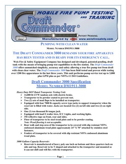
PUMPING WITH CLEAN WATER<br />
<strong>MODEL</strong> <strong>NUMBER</strong> DM1911<strong>3000</strong><br />
THE DRAFT COMMANDER <strong>3000</strong> DEMANDS YOUR FIRE APPARATUS<br />
HAS BEEN TESTED AND IS READY FOR ITS EMERGENCY CALL.<br />
Weis Fire & Safety Equipment Company has designed and developed, patented pending, draft<br />
tank with the means of bringing pump test capabilities to the fire station. The <strong>Draft</strong> <strong>Commander</strong><br />
<strong>3000</strong> offers unmatched simplicity, accuracy and safety allowing a true fire pump test from draft<br />
with clean clear water. The <strong>Draft</strong> <strong>Commander</strong> <strong>3000</strong> has been field tested and proven while testing<br />
over 1200 fire apparatuses in the last three years. This unit performs pump service test up to 3,000<br />
plus GPM plus as per NFPA11 ISO Guidelines.<br />
<strong>Draft</strong> <strong>Commander</strong> <strong>3000</strong> <strong>Specification</strong><br />
<strong>MODEL</strong> <strong>NUMBER</strong> DM1911<strong>3000</strong><br />
Heavy Duty DOT Rated Transporter Testing Unit:<br />
‣ 14,000 lb GVW tandem axle with electric brake.<br />
‣ Transporter to be powder coated to prevent rust.<br />
‣ Two (2) sets of mud flaps to be installed on transporter.<br />
‣ Equipped with four 7000 lb capacity screw type jacks to support transporter when the<br />
reservoir is filled with water. Jacks are located two (2) on left side and two (2) on right<br />
side.<br />
‣ One (1) ten thousand lb tongue jack.<br />
‣ Equipped with load E trailer tires, ICC Lights, and working lights.<br />
‣ 3M reflective tape on front, rear and sides.<br />
‣ Floor of transporter to be steel tread plate and to be powder coating.<br />
Note: Wood flooring is not acceptable.<br />
‣ Rear walk and step area of the transporter to be covered with slip resistant NFPA<br />
embossed aluminum tread plate approxamaly 24” X 70” attached by stainless steel<br />
fasteners.<br />
‣ Fenders of transporter to be covered with slip resistant NFPA embossed aluminum<br />
tread plate.<br />
<strong>3000</strong> Gallons Capacity Reservoir:<br />
‣ Reservoir is manufactured of heavy poly one inch on bottom and three quarters inch on<br />
side and top. Reservoir to be T shaped and attached to the transporter and mounted so<br />
it can not shift and will flex with the transporter.<br />
Page 1
‣ The mobile drafting water reservoir to have a section which is an independent suction<br />
drafting pit in the reservoir, and receives water flow through a special designed<br />
integrated sections of the reservoir which removes cavitations/disturbance and air from<br />
the water, so when water is entering the reservoir from high volume and pressure of<br />
water being pumped out of the drafting pit section from the apparatus being tested.<br />
This is to allow when the water reaches the draft pit section to maintain the correct<br />
water depth preventing water disturbance and air swirls causing apparatus to loose<br />
prime. The drafting pit section of the reservoir also to have four (4) antiswirl plates<br />
and a water temperature gauge to monitor water temperature.<br />
‣ Integrated water cooling system to help maintain a stable water temperature with two<br />
(2) 2 ½ inlets and one (1) 4” discharge to discharge warm water from reservoir. The 4”<br />
discharge is discharge at front right side of reservoir and controlled with quarter turn<br />
ball valve 2 1/2” NST male and caped.<br />
‣ All internal antiwater flow cavitation compartment sections to be made of ½” or<br />
larger heavy duty poly and supported and welded to withstand large volume of water<br />
that flow to the suction drafting pit compartment.<br />
‣ Reservoir clean out drain equipped with 2½” drain and controlled with a 2½” quarter<br />
turn valve and to discharge at right rear of transporter.<br />
‣ Located at the front of the test reservoir two (2) aluminum 1/8 tread plate stone<br />
shield (14” wide by 30 ¾” long) one located (1) on the right and one located (1) on<br />
the left side.<br />
‣ The mobile fire pump testing unit is designed to test fire pumps up to 3,000 GPM plus.<br />
‣ One (1) liquid site water gauge installed at rear of reservoir drafting pit.<br />
‣ Lifetime warranty on tank reservoir.<br />
<strong>Draft</strong>ing Tubes:<br />
‣ Two (2) 6”drafting tubes located in draft pit section of draft commander reservoir and<br />
equipped with special designed aluminum powder coated heavy duty 45° 6” 360° elbow<br />
swivels. The swivels are designed so you can position the apparatus at the rear, left, or<br />
right side. Swivels equipped with a grease zerk to lubricate swivels.<br />
Note: Swivel and dry hydrant elbows manufactured of PVC will not be accepted.<br />
Special Designed 45° Heavy Duty Powered Coated <strong>Draft</strong>ing Swivels:<br />
‣ On top of 360° elbow swivels a suction vacuum breaker to be installed and to be<br />
controlled at the rear of the transporter on each elbow.<br />
Hard Suction Hose:<br />
‣ Two (2) 17 ft of 6” flexible hard suction hose preconnected to the drafting tubes and<br />
stored on top of the <strong>Draft</strong> <strong>Commander</strong>. One end attached to the 360° elbow swivel and<br />
the other end equipped with 6” long handle swivel NFT female.<br />
‣ Two (2) hard suction trays to have hold down straps to secure the hard suction hose.<br />
The trays to be made of 1/8” aluminum plate 46” length by 8 ½” wide by 4 ½” depth.<br />
‣ Hard suction hose is clear which allows greater visibility of the water and making sure<br />
there is no air in the suction tubes.<br />
Extra Hard Suction Trays:<br />
‣ Two 10 ft of 6” flexible hard suction hose. The hose is clear which allows greater<br />
visibility of the water.<br />
‣ Couplings on the hard suction hose one (1) 6” swivel female L.H. N.S.T. thread at one<br />
end and a 6” male L.H. N.S.T. threads on the other end.<br />
‣ The hard suction hoses shall be stored one on each side of the tank between the fender<br />
wells and the tank body.<br />
Page 2
Two Stainless Monitors for Flowing Water and Pitot GPM Readings:<br />
‣ Four (4) inlets provided on stainless steel 4” round manifold, located at left rear and<br />
right rear of reservoir.<br />
‣ One (1) manifold equipped with 45° 4” male NST and equipped with a light weight 4”<br />
cap and chain for when pump testing using large diameter hose.<br />
‣ All other inlets are equipped with 45° elbow with 2 ½” female swivels N.S.T threads,<br />
and a 2 ½” N.S.T. Plugs Rocker Lug. Plugs to have heavy duty chains.<br />
‣ Each stainless steel manifold to be equipped with quarter turn ball valve to drain the<br />
manifold.<br />
‣ Two (2) large pitot compartments with hinged poly door for changing various nozzles.<br />
Compartment to be equipped with splash guard and defuser tip. Each pitot<br />
compartment to have chrome grab handle.<br />
‣ Pitot compartments to be equipped with quick disconnects so the pitot tube can be<br />
attached to monitoring station.<br />
‣ Pitot tubes to be installed in the flow station compartments, one each on left and right<br />
side of reservoir.<br />
‣ Two sets of flow tips 1”, 1 ¼” 1 ½”, 1 ¾”, 2”, 2 ¼” and 2 ½” mounted inside<br />
compartment.<br />
Mobile pump testing unit equipped with:<br />
‣ Equipped with a hand held that monitors the following:<br />
Air Temperature<br />
Atmospheric Pressure<br />
Altimeter<br />
‣ One (1) 3” water temperature gauge showing 0 – 200 degrees installed in the suction<br />
drafting pit compartment of the reservoir of the mobile test unit left rear.<br />
Mobile Pump Testing Monitor Station:<br />
‣ Monitor station dimension to be 20” wide by 18” tall by 6” depth.<br />
‣ One (1) aluminum telescoping tripod attached to the aluminum monitoring station<br />
equipped with two (2) 3 ½” pitot gauges 0160 PSI, one (1) 3 ½” vacuum apparatus<br />
gauge 030 inches and one (1) 3 ½” apparatus pressure gauge 0400 PSI. Each gauge is<br />
equipped with quick disconnects.<br />
‣ The pitot gauge is equipped with two (2) 30 ft high pressure hose one (1) for each pitot<br />
with quick disconnects.<br />
‣ Two (2) 10 ft high pressure hoses for the test vacuum and pressure plugs on the<br />
apparatus. One (1) end equipped with quick disconnects and the other end threaded<br />
swivel male to attach to the test plug on the apparatus.<br />
‣ All gauges mounted in the monitoring station and labeled. A large 5 ½” wide by 13” tall<br />
smooth board converter chart shall be etched on the face of the pump test station showing<br />
size of tips, flow gallons per minute and PSI reading for each tip used.<br />
Hose Storage Compartment and Misc. Equipment:<br />
‣ One large compartment 65” wide by 24” tall by 28” depth with V type bottom to store<br />
fire hose used for testing the fire apparatus. Large enough to store six (6) sections of 3”<br />
fire hose in 50 ft sections of coiled hose, spanner wrench, mallet, tools and etc.<br />
‣ Compartment to be ventilated and equipped with slip resistant NFPA embossed<br />
aluminum tread plate doors with pneumatic openers, stainless steel hinges and stainless<br />
handles.<br />
‣ Compartment to be made of ⅛” aluminum treaded plate.<br />
‣ Each door to be equipped with chrome lift handles<br />
Page 3
Side Compartments:<br />
‣ Two heavy duty side compartments 40” wide by 6 ½” tall by 7” depth (one (1) each side)<br />
in front of fenders shall hold all flow tips. With heavy duty mounting brackets and the<br />
compartment to have a raise up doors.<br />
‣ Two (2) folding steps are provided on the outside of each compartment to allow access<br />
to the flow station for changing tips.<br />
‣ Doors to be made of with slip resistant NFPA embossed aluminum tread plate with<br />
quick release hold downs.<br />
Additional Supplied Equipment:<br />
‣ Five 50 ft sections of 3” fire house with 2 ½” couplings. Hose is 600 pounds tested and<br />
double jacket.<br />
‣ One 6” male by 5” female NST thread light weight adapter<br />
‣ One 6” male by 4 ½” ” female NST thread light weight adapter<br />
‣ One 6” male by 4” female NST thread light weight adapter<br />
‣ One 2 ½ male NST by 3” male NST thread light weight adapters<br />
‣ One 6” male by 2 ½” female NST thread light weight adapters<br />
‣ One 2 ½” double female adapter NST<br />
‣ One 2 ½” double male adapter NST<br />
‣ One heavy duty rubber mallet<br />
‣ One net type UV heavy duty rated cover for top of open area of reservoir tank to keep<br />
reservoir clean<br />
‣ Two spanner wrenches<br />
Additional Requirements:<br />
‣ A list of 5 or more mobile pump testing unit users must be provided as per these<br />
specifications.<br />
‣ Operation and Training Manual along with a video will be provided upon delivery of<br />
the mobile pump testing unit.<br />
‣ The mobile pump testing unit has been in service and field tested for over five (5) years.<br />
‣ Descriptive information such as literature/brochures of these specifications to be<br />
furnished with bid.<br />
‣ Hands on personal training and operations.<br />
Weis Fire & Safety Equipment Co., Inc.<br />
The Exclusive Manufacture Of The <strong>Draft</strong> <strong>Commander</strong> <strong>3000</strong><br />
111 E. Pacific * P.O. Box 3467 * Salina, Kansas 674023467<br />
7858259527 * 18886899347 * 7858259538 Fax<br />
www.weisfiresafety.com<br />
“It’s a Weis choice”<br />
Page 4