No. 1, 1998 - Tribology in Industry
No. 1, 1998 - Tribology in Industry
No. 1, 1998 - Tribology in Industry

You also want an ePaper? Increase the reach of your titles
YUMPU automatically turns print PDFs into web optimized ePapers that Google loves.
YU ISSN 0354 - 8996<br />
lll<br />
I<br />
I<br />
voLUME'2o<br />
<strong>No</strong>1<br />
MARCH 1ee8.<br />
tribology <strong>in</strong> <strong>in</strong>dustry<br />
contents<br />
INTRODUCTION<br />
RESEARCH<br />
e. WfOVIe: Tiibology <strong>in</strong> <strong>in</strong>dustry - 20 Years With You 3<br />
C. GHEORGHIES, O. GHEORGHIES: Predicrion of Case-harden<strong>in</strong>g<br />
Steel Behaviour <strong>in</strong> Roll<strong>in</strong>g Tiibosystem 5<br />
D. AIv[AF!{I{DEI, M. COZMINCA, D. SEMENCIUC: Research and<br />
Method Concern<strong>in</strong>g the Experimental Values of the Average Friction<br />
Coefficient on the Tool's Fl<strong>in</strong>k <strong>in</strong> Mach<strong>in</strong><strong>in</strong>s of Carbon Ste-els with<br />
Speedsuptol000m'm<strong>in</strong>-l ...:... 10<br />
E FLORIAN, D. L ALEXANDRU: Synthetic <strong>No</strong>n-newtonian Fluids<br />
Based on Polymer Gels II. Rheology of Polymer Gels for Determ<strong>in</strong>e<br />
Their Flow <strong>in</strong> Pipe-l<strong>in</strong>e 16<br />
V. F. BEZAIZICHNY, V V. NEPOMILUEV: Calculation of The<br />
Cutt<strong>in</strong>g Conditions Tak<strong>in</strong>g <strong>in</strong>to Account The Criteria of The Cost<br />
and Productivity 27<br />
T F. KALMYKOVA T M. MOISEEV,\ O.V KHOLODILOV:<br />
On Statistical Description of Solids Friction 24<br />
M. OGNJANOVIC, P. OBRADOWC: Modell<strong>in</strong>gof High-pressure<br />
Dynamic Seal<strong>in</strong>g Jo<strong>in</strong>ts 27<br />
NEWS<br />
JJ<br />
BOOKS AND JOURNAIS<br />
SCIENTIFIC MEENNGS<br />
35
B.IVKOWC<br />
<strong>Tribology</strong> <strong>in</strong> <strong>in</strong>dustry - Z}Years With You<br />
In already distant 1978, The Council<br />
of Faculty of Mechanical Eng<strong>in</strong>eer<strong>in</strong>g<br />
<strong>in</strong> Kragujevac had brought a decision,<br />
at the proposal of the Scientific-Educational<br />
Board, on beg<strong>in</strong>n<strong>in</strong>g<br />
with publication of a scientific journal<br />
entitled "TRIBOLOGY IN IN-<br />
DUSTRY'',<br />
The orig<strong>in</strong>s of the entitled "TRIBO-<br />
LOGYIN INDUSTRY" journal lie <strong>in</strong><br />
Publications of Laboratory for Metal<br />
mach<strong>in</strong><strong>in</strong>g and Tiibolory, that were<br />
published occasionally, as edition.s of<br />
Faculty of Mechanical Eng<strong>in</strong>eer<strong>in</strong>g,<br />
s<strong>in</strong>ce I974. Dur<strong>in</strong>g that period, from<br />
1974. till 1978., 10 issues were published,<br />
<strong>in</strong> which the results were presented<br />
of the scientific-research<br />
work, realized through projects,<br />
ma<strong>in</strong>ly form the area of the tribologr<br />
of metal cutt<strong>in</strong>g.<br />
Members of the First Joumal's Council<br />
were: S. Spasojevii, from The<br />
Chamber of Commerce of Serbia;<br />
Mr. V. Kaliian<strong>in</strong> and Z. Prokii -<br />
ZCZ;Prof. Dr S. Savar - Faculty of<br />
Mach<strong>in</strong>ery and Shipbuild<strong>in</strong>g, Zagreb;Prof.<br />
Dr D. Zelenovii - Faculry<br />
of Technical Sciences, <strong>No</strong>vi Sad; Prof.<br />
Dr Branko Ivkovii - Faculty of Mechanical<br />
Eng<strong>in</strong>eer<strong>in</strong>g, Kragujevac;<br />
M. Voljevica - Faculty of Mechanical<br />
Eng<strong>in</strong>eer<strong>in</strong>g. Mostar; Z. Milut<strong>in</strong>ovii<br />
- The Chamber of Commerce of Kragujevac;<br />
and M. Lt.zic - Faculry of<br />
Mechanical Eng<strong>in</strong>eer<strong>in</strong>g, Kragujevac.<br />
The Council rvas rvork<strong>in</strong>g, mii<strong>in</strong>ly<br />
with these members and small changes,<br />
until 1992., when ceased the need<br />
for its eistence.<br />
The First Editorial Board of the Journal<br />
consisted of: Prof. Dr B. Ivkovii -<br />
Faculty of Mechanical Eng<strong>in</strong>eer<strong>in</strong>g,<br />
Kragujevac - Editor <strong>in</strong> Chief;Prof. Dr<br />
R. Zgaga - Faculty of Mach<strong>in</strong>ery and<br />
Shipbuild<strong>in</strong>g,Zagreb; prof. Dr S. Sekulii<br />
- - Faculty ofTechnical Sciences,<br />
<strong>No</strong>vi Sad; Prof. Dr M. Radovanovii -<br />
Faculty of Mechanical Eng<strong>in</strong>eer<strong>in</strong>g,<br />
Belgrade; Mr. Z Palundii - Faculty of<br />
Mechanical Eng<strong>in</strong>ee r<strong>in</strong>g, Kragujevac<br />
- Secretary; F. Pavlovii - Faculty of<br />
Mechanical Eng<strong>in</strong>eer<strong>in</strong>g, Mostar; R,<br />
Nikolii - FAM, Km(evac; and M. Simovii,<br />
Editor.<br />
S<strong>in</strong>ce 1986. till 1992. mernbers of Editorial<br />
Boarcl were also: Prof. Dr A.<br />
Rac, - Faculty of Mechanical Eng<strong>in</strong>eer<strong>in</strong>g,<br />
Belgrade; Prof. Dr J. Vite-<br />
Zan<strong>in</strong> - Faculty of Mechanical Eng<strong>in</strong>eer<strong>in</strong>g,<br />
Ljubljana; Prof. Dr M.Lazil<br />
- F:rculty of Mechanical Eng<strong>in</strong>eer<strong>in</strong>g,<br />
Kragujevac.<br />
S<strong>in</strong>ce 1991. until present time, the<br />
Journal is edited by an <strong>in</strong>ternational<br />
Editorial Board rvhose members are<br />
famous scientists from several countries<br />
(Belarus, Poland, England,<br />
IJSA, \'ugoslavia, N{acedonia). The<br />
core of the Boirrd consists of scientific<br />
workers fiom Faculties of Mechzrnical<br />
Engirteer<strong>in</strong>g flom Kragujevac<br />
and tselgrade, and Faculty of Technical<br />
Sciences from <strong>No</strong>vi Sad. With<br />
translation of texts for years are engaged<br />
Prof. Dr RuZica Nikolii (English)<br />
and Mr, A. Milenkovi6 (Russian).<br />
The structure of the Journal did not<br />
vary sirnificantly <strong>in</strong> past years. Constant<br />
sections, until today, were IN-<br />
TRODUCTION, RESEARCH,<br />
BOOKS AND JOURNALS, and<br />
SCIENTIFIC MEETINGS. Occasionally,<br />
there were sections like<br />
TRIBOLOGICAL DICTIONERY,<br />
FOR DIRECT PRACTICE, and<br />
NEWS, thert existed <strong>in</strong> several issues,<br />
but except for the NEWS, they did<br />
nt-lt get the permanent character.<br />
Abstracts of all the papers were published,<br />
until 1992., both <strong>in</strong> English<br />
and <strong>in</strong> Russian, on the last pages of<br />
Journal, <strong>in</strong> fcrm of cards, as it is frequently<br />
done <strong>in</strong> scientific and expert<br />
journals. S<strong>in</strong>ce 1992., however, the<br />
structure of the Journal has changed<br />
somewhat. Abstracts of each paper<br />
are pr<strong>in</strong>ted, <strong>in</strong> English and Russian,<br />
at the end of each paper, what seems<br />
to be more convenient for the readers,<br />
1o have complete papers and<br />
abstracts at one place, and abstract irr<br />
Serbian is pr<strong>in</strong>ted at the beg<strong>in</strong>n<strong>in</strong>g of<br />
each paper, below the title.<br />
Besides publish<strong>in</strong>g the Journal <strong>in</strong><br />
Serbian, with abstracts of papers <strong>in</strong><br />
English and Russian, s<strong>in</strong>ce 1996. as<br />
separate issue is published the English<br />
version of the Journal, with separate<br />
ISSN number, entitled TRI-<br />
BOLOGY IN INDUSTRY. In the<br />
first years of publish<strong>in</strong>g the Journal<br />
l'rad covered mostly the are of tribo-<br />
Iogy of cutt<strong>in</strong>g, and tribometry,<br />
Tibolog, itt itttlustry,, Volume 20, <strong>No</strong>. 1, <strong>1998</strong>.<br />
3
though there were also published articles<br />
from other areas of tribologry.<br />
In last several years, however, <strong>in</strong> both<br />
issues (<strong>in</strong> Serbian and English) are<br />
present papers from almost all areas<br />
of tribology. In the Journal are present<br />
papers from Tiibology o[ manufactur<strong>in</strong>g<br />
processes (cutt<strong>in</strong>g and metal<br />
form<strong>in</strong>g), Tiibology of mach<strong>in</strong>e<br />
elements, Tiibomaterials, Application<br />
of lubricants and lubrjcation systems,<br />
Diagnostics and ma<strong>in</strong>tenance<br />
of the tribosystems, Tiibometry, and<br />
Terotechnologv.<br />
In past n<strong>in</strong>eteen years, the largest<br />
number of papers were published by<br />
authors that were employed at Yugoslav<br />
Universities, scientific <strong>in</strong>stitutions<br />
and research departments <strong>in</strong><br />
lead<strong>in</strong>g <strong>in</strong>dustrial systems. However,<br />
<strong>in</strong> last years, are present more and<br />
more papers of domestic authors that<br />
are work<strong>in</strong>g <strong>in</strong> <strong>in</strong>clustrial systems on<br />
jobs of ploclucts clevelopment, technology<br />
or rna<strong>in</strong>tenunce of the production<br />
and other equipnrcnt.<br />
The significant number of paperswas<br />
published <strong>in</strong> the Journal by authors<br />
from Slovenia, Croatia and Bosnia,<br />
until 1991.<br />
The Journal TRIBOLOGY IN IN-<br />
DUSTRY rvas all these years, and still<br />
is, the only Journal of scientifi character,<br />
frorn the area clf Ti'ibcrlogy, on<br />
wider former Yugoslavian spaces,<br />
from Ljubljana to Skopic.<br />
About one third of all papers was<br />
published by foreign authors. Among<br />
them there were papers written by<br />
authors from Russia, Belerrus, England,<br />
United States, Polancl, Greece,<br />
Bulgaria, Ronrani a, Japan, Germany<br />
and Slovakia.<br />
The users of the TRItsOLOGY IN<br />
INDUSTR Journal rvere. until 1991..<br />
all the libraries of all tlniversities,<br />
Faculties of Mechanical Eng<strong>in</strong>eer<strong>in</strong>g,<br />
and Scientific <strong>in</strong>stitutes <strong>in</strong> Republics<br />
of former Yugoslavia, as well as all<br />
the larger and medium size <strong>in</strong>dustrial<br />
systems of metal work<strong>in</strong>g <strong>in</strong>dustry on<br />
those spaces. The number of users<br />
had decreased s<strong>in</strong>ce 1991., from<br />
known reasons, so todzry the Journal<br />
is sent to about 220 users <strong>in</strong> Yugoslavia<br />
and 60 <strong>in</strong> other countries.<br />
Until 1991. the greater part of puhlislrirrg<br />
costs wus crtveretl from the scll<strong>in</strong>g<br />
of the Journal, through subscription.<br />
Last several years, the Journal is<br />
be<strong>in</strong>g published ma<strong>in</strong>ly due to f<strong>in</strong>ancial<br />
support of M<strong>in</strong>istry for Science<br />
and Technologry of Republic of Serbia<br />
and Federal M<strong>in</strong>istry for development,<br />
science and environment, s<strong>in</strong>ce<br />
due to exist<strong>in</strong>g state of the domestic<br />
<strong>in</strong>dustry, it was not possible to prov'ide<br />
for enough f<strong>in</strong>anc<strong>in</strong>g from subscriptions.<br />
In this year, <strong>in</strong> which the Journal<br />
TRIBOLOGY IN INDUSTRY comes<br />
twentieth time before domestic<br />
and foreign scientific and expert public,<br />
with both issues <strong>in</strong> Serbian and<br />
English, the special efforts will be<br />
done for Journal to enter iill the environnents<br />
where jobs are done, of<br />
both scientific ancl e.rpert character,<br />
that are concerned with rnak<strong>in</strong>g the<br />
greater gross product through decreas<strong>in</strong>g<br />
the production costs and <strong>in</strong>creas<strong>in</strong>g<br />
the work produ,-'tiviry.<br />
The productivity Ievel <strong>in</strong> our <strong>in</strong>dustrial<br />
systems and the low cross national<br />
product per capita, are consequences,<br />
to the great extent, of <strong>in</strong>sufficiently<br />
organized constant fight for<br />
reduc<strong>in</strong>g the iriction and wear, <strong>in</strong> numerous<br />
tribo-mechanical systems<br />
both <strong>in</strong> <strong>in</strong>dustry and transport. The<br />
effort is go<strong>in</strong>g to be done, througlr<br />
Journal TRIBOLOGY IN INDU-<br />
STRY, to po<strong>in</strong>t out to a large number<br />
of people to the fact, known <strong>in</strong> all the<br />
developed countries, that, by application<br />
of exist<strong>in</strong>g. and creation of the<br />
new tribological knowleclge, the conditions<br />
arc clcirted for <strong>in</strong>creas<strong>in</strong>g significantly,<br />
both gross national product<br />
and productivity of exit<strong>in</strong>g<br />
<strong>in</strong>dustrial and transportation systems,<br />
even without expensive <strong>in</strong>vestments<br />
ancl <strong>in</strong>troduc<strong>in</strong>g the new technoli.rgies.<br />
Erpelience frorn the developed<br />
worlcl po<strong>in</strong>t that by application<br />
of tribological k-nowledge and solutions,<br />
even 40 times larger profit can<br />
be realized rvith respecl to <strong>in</strong>vestments.<br />
In some <strong>in</strong>dustrial systems<br />
energy consurnption decrease, through<br />
application of tribological knowledge,<br />
lvas as much as 10 %. It is<br />
useful, on this occasion too, to rem<strong>in</strong>d<br />
ourselves that by application of<br />
trilrrrlor-lictrl soltttiorts, sirv<strong>in</strong>gs irre<br />
also realized by lower<strong>in</strong>g the ma<strong>in</strong>tenance<br />
costs, lower<strong>in</strong>g the production<br />
costs, that are appear<strong>in</strong>g due to<br />
breaks <strong>in</strong> production processes caused<br />
by rvear of elements and production<br />
and other equiprnent, by lower<strong>in</strong>g<br />
the <strong>in</strong>vestnrents <strong>in</strong>to the new<br />
eqr-riprnent (the work<strong>in</strong>g life is <strong>in</strong>creasecl<br />
fclr the exist<strong>in</strong>g equipnrent), by<br />
lo"ver<strong>in</strong>g the consunrption of lubricants<br />
arrtd by lowenng t.he latror costs.<br />
In Jubilee vear, an issue is go<strong>in</strong>g to be<br />
reserved forpublish<strong>in</strong>g the review papers<br />
from different areas of tribology,<br />
<strong>in</strong> order to provide for the readers the<br />
useful <strong>in</strong>sight <strong>in</strong>to the exst<strong>in</strong>g level of<br />
our knowledge, and to create conditions<br />
for fbnn<strong>in</strong>g the new research<br />
progriilxs and new approaches to application<br />
of exist<strong>in</strong>g knowledge from<br />
the area of tribology <strong>in</strong> <strong>in</strong>dustrial and<br />
Iransportlrt ion systems.<br />
'fribologt itt itultLrtty, Volurne 20, <strong>No</strong>. 1, <strong>1998</strong>.
UDK 62i.9.025.?.003<br />
C. GHEORCHTES, O. GHEORGHIES<br />
Prediction of Case-harden<strong>in</strong>g Steel<br />
Behaviour <strong>in</strong> Roll<strong>in</strong>g Tribosystem<br />
I<br />
O cf<br />
|'rl<br />
U)<br />
tlJ<br />
cc<br />
Irt order to follow the tribol
COMMANDING PARAMETERS<br />
constructlve<br />
(s.)<br />
INPUT<br />
€t<br />
Superficial<br />
iayer<br />
parameters<br />
(x1,X2,...,x0)<br />
'liibosystem<br />
param(: [ers<br />
(dr, dz)<br />
fu'=f {t.s..c- }<br />
dt<br />
JL<br />
i=l-6<br />
!; = r1',t,,cr \<br />
I<br />
Wear<br />
r<br />
Supcrficial<br />
1!)<br />
parcmcters<br />
'Ii'ibosvstcnr<br />
z-\<br />
paranietcrs (C'1)<br />
(dr, dz) \--'l<br />
OUTPUT<br />
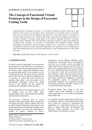
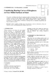
Fig. 1. Cybernetic tnodeL for tribosyslurr<br />
ditions; the selection of the quantit;rtive and qualitative<br />
parameters show<strong>in</strong>g damage degree; the f<strong>in</strong>d<strong>in</strong>g of the<br />
mathematical models <strong>in</strong> order to establish the dependence<br />
between the damage choice parameters and tribophysicai<br />
ones.<br />
3. CYBERNETIC MODELLING OF<br />
TRIBOSYSTEMS<br />
ln order to establish and to control the action of the ma<strong>in</strong><br />
factors that determ<strong>in</strong>e the damage process by pitt<strong>in</strong>g, for<br />
the tribosystem, the concept of structural cybernetic model<br />
[10, 11] has been used. For the same purpose, Czichos<br />
[3] -<strong>in</strong> some rvorks -has used the concept of the energetically<br />
wbernetic model. Us<strong>in</strong>g of the structural cybernetic<br />
model enabled to characterue the surface layer frorn<br />
the physical po<strong>in</strong>t of view and not energetic.<br />
In frame of the structural cybernetic model, the tribosystem<br />
is presented as a black-box where are designed<br />
<strong>in</strong>put parameters (.1, Cr); command<strong>in</strong>g parameters (U);<br />
output parameters (S,l C,') and the paraneters which<br />
assess the darnage degree of the surface layer, as e. g.<br />
wear. This model, rvhich allows to follow -<strong>in</strong> a systematic<br />
manner-tire changes of the <strong>in</strong>put parameters of the surface<br />
layer subjected to pitt<strong>in</strong>g process, is presented <strong>in</strong><br />
figure 1.<br />
The <strong>in</strong>put-output pararneters can be grouped as: geometrical<br />
(macro and microgeometry -q);mechanical (hardnes.s<br />
- rJ, tension state r3); physicometallurgical (chernical<br />
compositionr;, structure -;r5, purity -.16) parameters.<br />
Ones from mentioned parameters, for e. g., hardness -<br />
rr, tension state --r.i and structure -xj, ciur be changed <strong>in</strong><br />
a convenient nturner. In this rvay, the durability of the<br />
tribosystenr can be contrcrllecl, with<strong>in</strong> certa<strong>in</strong> lirnits, at<br />
one's choice.<br />
Parameters (C1) of the tribosystem can be: level of noise,<br />
shape and dimension of contact area, d1, clearance between<br />
triboelements, d2.<br />
Command<strong>in</strong>g parameters ([.f, called external factors,<br />
are the parameters which can modiff ones from the<br />
parameters of the surface layer. These parameters can<br />
be grouped <strong>in</strong>: constructive (shape of triboelement-U1,<br />
dimension of triboelement - U2); work<strong>in</strong>g parameters<br />
(k<strong>in</strong>ematics- U3, energetics - Ua, work<strong>in</strong>g medium- U-5).<br />
In the bfack-box, the <strong>in</strong>pui paranreters X; (i=1-6) are<br />
subjected to changes -<strong>in</strong> relation with time, t, or depth, h<br />
(as <strong>in</strong> this paper) under action of command<strong>in</strong>g parameters,<br />
Ur; (i=l-5). The knowledge of function 'f' or "9"<br />
allow to describe the evolution of ,\-parameters and,<br />
f<strong>in</strong>ally, the estimate both the history ancl prediction surface<br />
layer behavior <strong>in</strong> various stress conditions (e. g.<br />
pitt<strong>in</strong>g process).<br />
4. USED MATERIALS, PITTING TESTING<br />
MACHINE.<br />
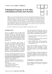
In order of follou' the tribological behavior of case-harden<strong>in</strong>g<br />
steel l2MoMnCr12XS, the roll<strong>in</strong>g pure frictfon<br />
test on a tribomoclel have been used. The tribomodelrvas<br />
mounted on an orig<strong>in</strong>al four-ball mach<strong>in</strong>e. In figure 2 it<br />
is presented this tribomoclel where: 1-test<strong>in</strong>g roller; 2-<br />
press<strong>in</strong>g roller: 3-lever for transmission of press<strong>in</strong>g forces,<br />
F. The test<strong>in</strong>g triboelement (test<strong>in</strong>g roller) was melnutactured<br />
of case-harden<strong>in</strong>g steel. This roller had the<br />
d<strong>in</strong>rensions: Qoutsi,le = 30 tnnt, Qi,tsila : 20 mm; width,<br />
l=12 mm.It was subjected to el thermal harden<strong>in</strong>g treatment<br />
(heat<strong>in</strong>g <strong>in</strong> rnelhane gas at 850-B60<br />
oC and ma<strong>in</strong>ta<strong>in</strong><strong>in</strong>g<br />
a periocl of two hours, be<strong>in</strong>g followed by a quench<strong>in</strong>g<br />
<strong>in</strong> oil ancl anrrezrl<strong>in</strong>{). The thickness of the<br />
hardcned layer rvas of 0.6-0.8 rrtm and the hardness of<br />
62 i- 3 I-IRC. The pressure of contact, P, has been chosen<br />
6<br />
I|iboiogt itt itultrstry, Voltrnre 20, <strong>No</strong>. 1, <strong>1998</strong>.
at ciepth /r;<br />
b) the width 8211 of (2,/1) diffraction l<strong>in</strong>e correspond<strong>in</strong>g<br />
to lrirrtensits phase from case-ltarden<strong>in</strong>g steel (8211 is a<br />
size proporl ioirill to tetragonality degree, cia, of martensite<br />
phase;<br />
c) the rvidth 8220 of (220) diffrtrction l<strong>in</strong>e of ferrito-perlitic<br />
phase from steel (8226 is a size proportional to <strong>in</strong>ner<br />
second order tension, .t11 from crystall<strong>in</strong>e lattice);<br />
d) the ratio (l,,,<strong>in</strong>ll,rn) which is proportional to dislocation<br />
density,p, from crystall<strong>in</strong>e lattice (1,r,;, and I,nor) are<br />
respectively m<strong>in</strong>imum and maximumot Q20) diffraction<br />
l<strong>in</strong>e.<br />
Fig.2. Used tibonndel<br />
<strong>in</strong> accordance rvith SKF standarcl and it had the value<br />
1900 MPa, 3300 MPa, 4700 MPa. Dur<strong>in</strong>g the pitt<strong>in</strong>g test<br />
of up to 106 cvcles the l<strong>in</strong>ear-contact benveen triboelements<br />
were cont<strong>in</strong>uously lubricated with a special oil,<br />
ensur<strong>in</strong>g a thermostatic control ii c\0't- lnC.<br />
5. EVALUATION OF THE STR.UCTUITAL<br />
CHANGES, EXPERIMENTAL RESULTS.<br />
From all parameters of the surface layer, x;, i=1-6, only<br />
tension state, -rJ, and structure, -r5, have been studied.<br />
Thus, their distribLrtions (as value) over the depth, /r, of<br />
the surface laYer after pitt<strong>in</strong>g lcst were <strong>in</strong>vestigatecl. In<br />
this aim, the tested rollers u,ere electrochemically polished<br />
us<strong>in</strong>g a spccialii.' nranutactured <strong>in</strong>stallation.<br />
The chemical composition of the electrolyte was: II jPOa<br />
- 750 cnts; H2SCa-t8A on]; Croj-100g; H2O-280 rnl.<br />
Density of electric:tl cr.lrrent of electrolytic cell rvas l=0.7<br />
Alcrn2.Dur<strong>in</strong>g polish<strong>in</strong>g the sample (anocle) by means of<br />
an eng<strong>in</strong>e wris rotat<strong>in</strong>g rvith frec;rrency of 6.25 Hz. T'his<br />
motion assures lr homogeneity of both cclncentration and<br />
temperature of electrolytic bath. Also, a cool<strong>in</strong>g coil did<br />
not allow heat<strong>in</strong>g of the solution. By apply<strong>in</strong>g an electrolytic<br />
polish<strong>in</strong>g technique, lal,ers of 50tr<strong>in</strong>r thickness',vere<br />
successively rernoved from the tested triboelement.<br />
Alier eacl: polish<strong>in</strong>g, the tested roller was mounted on a<br />
X-ray diffraction equipment, type DP.ON-3 (XMoKe,<br />
tl=38kV, I:22 rrt4, .91=l mnt, Sz.=0.1p74). From the13<br />
andx5 parameters, have been evaiuated:<br />
a) relative percentage of residual austenite, YR(o/o),<br />
us<strong>in</strong>g the relation: VR(%) = ftul(a/o)]n*s [R4(%)]1,=0<br />
is the percentage of resiCual austenite at sample surface.<br />
IRA(%)]n*o is the si'rme size <strong>in</strong>sicle of the surface layer<br />
In figure -3 it is presented the depen
30,0<br />
FcL<br />
25,0<br />
t25<br />
A. P= 01,/Po<br />
_,1 -e- P= 1900 MPc]<br />
_EF p- 3300l4pci<br />
_o,. p= 4700 t1p0<br />
0,2 0,3 0,1,<br />
_* h (mnr)<br />
Fig.4. Depetdence of 8211 ott lr<br />
as relative residual austenite; this fact can expla<strong>in</strong>ed by<br />
appearance of high temperatures <strong>in</strong>ner surface layer<br />
which have various values at different depths; the correlation<br />
between the two sizes displays transformations of<br />
type Fea(TBC) - Fca(BCC) and Fey - Fea(BCC) or<br />
Fea(TBC);<br />
c) the size .8277 strongly varies up to 200 prre <strong>in</strong>side the<br />
surface Iayer and it follows a stabilization.<br />
In figure 5 is displayed the dependence of size<br />
8226-oflh). From presented data results: the <strong>in</strong>ner second<br />
order tensions have a peak between 100-200 pm<br />
depth, while the cuwes IJ2ao = Bzzo&) are alternately<br />
placed for the three values of the pressure P. This can be<br />
accounted for by changes of the prevail<strong>in</strong>g mechanical<br />
and thermal effects at variorrs depths dur<strong>in</strong>g pitt<strong>in</strong>g tests.<br />
Fig. 5. Dependcnce of B2x1 ort h<br />
In figure 6 it is presentecl the evolution on surface layer<br />
depth of the size (l,,rirlt,or)22a. The shapes of designed<br />
cun'es are similar for the three pressures. At P=0 MPa<br />
maximum of dislocations density is located at a depth of<br />
3001.un<br />
<strong>in</strong>side the surtace layer. At pressure of 1900 MPa<br />
8<br />
ll, a<br />
l?i,,<br />
oq<br />
nfl<br />
0,7<br />
0,rl<br />
I<br />
f<br />
z\- p=rl j,4po<br />
C) '.f',.'1900 lt,lPa<br />
{.t P- 3300 I'll"ci<br />
l- P =1, i 0C lv1 Ptt<br />
|<br />
0,1<br />
|<br />
0,2<br />
- i--<br />
0,3<br />
Fig" 6. Dt:ptndrnce af (l,rullrnut)220 ort lt<br />
is found a decrease of the general dislocations density<br />
level. The maximuln of this cun'e is situated near sut{ace<br />
of the sur{ace lrryer. For 1' = ,}300 tr[Pa zrnd I'>:4700 MPa<br />
the maxima of curyes remove <strong>in</strong>ner of the surface layer,<br />
hav<strong>in</strong>g the same values ancl are located <strong>in</strong> the sarne area<br />
approximately. This fact shorvs that the anneal<strong>in</strong>g thermal<br />
treatment is not enough or should be performed by<br />
an another diagram <strong>in</strong> orcler to reduce the level of the<br />
dislocations density.<br />
6. CONCLUSIONS<br />
1+-- _<br />
J).,1:iii<br />
l. lr<br />
() /, al r,<br />
-t<br />
> Us<strong>in</strong>g the concepts of the tribosystem, tribomodel,<br />
triboelement and surface layer it was possible to prepare<br />
a pitt<strong>in</strong>g test<strong>in</strong>g program <strong>in</strong> order to establish the<br />
tribological behavior of case-harden<strong>in</strong>g steel 21<br />
MoMnCrl2XS recommended for replac<strong>in</strong>g the bear<strong>in</strong>g-roll<strong>in</strong>g<br />
steel RUL-1,<br />
> From the clistribution on the surfac:e layer depth of the<br />
structural changes IXS=XS&) andX5:y511't)] - dist<strong>in</strong>guished<br />
by X-ray diffraction nrethod-the follorv<strong>in</strong>g<br />
conclusions can be drawn:<br />
a) the existence - <strong>in</strong> <strong>in</strong>ner of the surface layer of the<br />
case-harden<strong>in</strong>g steel - of the diference behveen mechanical<br />
and therrral effects which develop clur<strong>in</strong>g<br />
pitt<strong>in</strong>g test; this fact is consiclered as a negative factor<br />
on the structural and d<strong>in</strong>rensionul .stabilities<br />
b) the existence on surflce layer depth of a nonhomogeneity<br />
fol <strong>in</strong>ner secontl order tensious which, at<br />
ctepth of 100-2001trn, has a naximum value; this fact<br />
shows that it is possible that sorne microcracks appear<br />
<strong>in</strong> this area<br />
c) the existenc:e of a contact pressure limit which the<br />
case-harden<strong>in</strong>g steel can be stressed; a higher pressure<br />
(over the nrentioned iimit) can Iead to appearance of<br />
-some phase transformations (e. g. Fea*Fey) which<br />
are not recr.rmrnencleci for case-hurden<strong>in</strong>u steel.<br />
Ii'ibologt irt itultts'try, \blume 20, <strong>No</strong>. 1, <strong>1998</strong>.<br />
)
The presenied nrethodoJr:gy ztlrr,l obta<strong>in</strong>ecl cl:rta cart L,'c<br />
used <strong>in</strong> eng<strong>in</strong>eer<strong>in</strong>g design <strong>in</strong> order tL) repiace some<br />
expensive mat erials with other cheaper but with sirniiar<br />
performances.<br />
7. REFERENCES<br />
11.) Col<strong>in</strong>s, L ,,1, Failure of Materials <strong>in</strong> N{echanical Design,<br />
Ltd. John Wiley. New York, 1981<br />
[2.) Grudu. L, Palaghian, L., Ghectrghies;'C., Structural<br />
Modifications <strong>in</strong> the Superficial Layer of Metallic<br />
Materials <strong>in</strong> Wear and Fatigue Processes, Proceed<strong>in</strong>gs<br />
of International Tribologry Conference, Nitgoya<br />
1990, Japan. vol. I, pp. 2M-214<br />
13.) Czi c h o s,.I/., Systernanalyse und Physi k tribologische<br />
Vorgange, Teill, Grundlzrten, Schmirtechnik Tribologie,<br />
32, 6.le1(t<br />
14.) Djatnhmedov, A.11. F iziko stohasticeskoe tribomodelirovanie,<br />
Izd. Elm. Baku, 1988<br />
15.) Ishlirurkii, A. 1., K'agelski, L V. c/. a/., Problenri iznashivanija<br />
tverdih tel i aspctirnehaniki, Trenie i iznos.4.<br />
1986<br />
[5.) Stcfntrcsctt, L, Gheorglties, C., 'l'he irrflrrence of 'I'hermornagnetic<br />
Treatment Applied to Roll<strong>in</strong>g-tsear<strong>in</strong>g<br />
Steel, Acta Tribologica, ),2,1994, pp. 13'l-146<br />
17.] Ilabic, M", Jerenic, I]., Miiit:, iv".,<br />
'frillological ['roperties<br />
of Cra<strong>in</strong> Surfaces, Proceed<strong>in</strong>gs of BAI-KAN-<br />
-fRiB'96, Thessaloniki, Greece pp. 151-i58<br />
18.)Gkeorylies, C., Structur:al Changes Dur<strong>in</strong>g Friction,<br />
Wear and Fatigue Procceses (<strong>in</strong> r
-l<br />
[- rf- iitlrll<br />
llili<br />
llll-l<br />
L _lL_ il _,,<br />
I<br />
O cc<br />
ill<br />
o<br />
LU<br />
E<br />
r--l<br />
tl<br />
L__l<br />
li<br />
li<br />
i_i<br />
UDK 621 .9 r q.2.001.^12<br />
D. A\'IARANDEI, M. COZMINCA, D" SEL'IENCIUC<br />
Research and Method Concern<strong>in</strong>g<br />
the Experimental Values of the<br />
Average Friction Coefficient on the<br />
Tool's Flank <strong>in</strong> Mach<strong>in</strong><strong>in</strong>g of Carbo4<br />
Steels with Speeds up tc 1600 m.m<strong>in</strong>-l<br />
This paper refers to tl'te frictiort phetnmetton ott the too[s Jlat* itt tunittg. A tnetlttxl t*cr! Io delerntirte tlrc<br />
at,erage coefficient of fictiotrott tlte tool's flank is presetiled. Thi.s rnetlrctl is.suslaitrcLl by erlteimuttal rc.re arclt<br />
obta<strong>in</strong>ul <strong>in</strong> high speul turuirry of carbon steels (v',itlt spculs u1t to 1000 nt'ntiti' )<br />
1. THEORETICAL CONSIDERATIONS<br />
Know<strong>in</strong>g the value, the distribution for the physical cornponents<br />
(the friction force and the plastic deformation<br />
force) and the ratio between them is very important <strong>in</strong><br />
theory as <strong>in</strong> practice because all these <strong>in</strong>fluence the<br />
wear's growth irnd its evoluticln speed. As the costs needed<br />
to restore the cutt<strong>in</strong>g properties of the tool and to<br />
replace it are go<strong>in</strong>g to <strong>in</strong>crease the fabrication costs, it is<br />
very important to manage the friction and wear phenomenons<br />
<strong>in</strong> metal cutt<strong>in</strong>g.<br />
A lot of scientific papers were publishecl, regard<strong>in</strong>g the<br />
external friction phenomenon, the friction coefficient<br />
and the factors of <strong>in</strong>fluence, but the results are sometime<br />
different and mosf conrrnonly they have gotten different<br />
<strong>in</strong>terpretations. Ar e.rplarnzrtion for all these is the fact<br />
that all these as1-.sc1s \\'erc lrezrtetl us<strong>in</strong>g yarious simplify<strong>in</strong>g<br />
hypotheses.<br />
Sorne authors consicler that between the tool and the<br />
chip, or befween the piece and the chip, or between the<br />
tool and the piece, is a dry adhesive or abrasive friction,<br />
and some other authors solve the same problems for<br />
humide friction (consrder<strong>in</strong>r the cutt<strong>in</strong>g fluid <strong>in</strong>volved)<br />
or they consider that on the contact surface is a rnLxed<br />
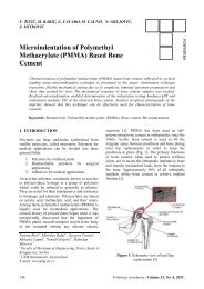
friction, figure 1, [8. 19]. The bibliography relative to that<br />
subject shows that <strong>in</strong> order to detenl<strong>in</strong>e the fl.ictiun<br />
Reader Dr. Etry. DtLrnitnt,4ntarutttlei,<br />
"Stefarr ccl Marc" Uttit,crsity of Succat,a,<br />
Professor Dr. Ette. lllircca cotnitu'a,<br />
"Glrcorghe AscLclti" Urtiversitlt of J,1t1,<br />
Lcctttrcr Eng. Datt,Setrtcttcitu',<br />
"Stefatt cel Mara" Unitl:rsi4, oJ'Srtceot,n<br />
WORKPIECE<br />
adhesion tvelditrg =!-<br />
adhesion r:ones<br />
Fig. I. TIte,eat coutact s,.l,,j!,!rc|jJt,ntetaI cuttitts usutS<br />
components and the friction coefficient both analytic and<br />
experimental rnethods itre used.<br />
The real extern friction forces <strong>in</strong> metal cutt<strong>in</strong>g depend<br />
on the real ccntact srlrfaces betrveen the tool and the<br />
piece [4, 9]. For tiie tools with preset edge (figurc 2), the<br />
friction surfaces fbr a section given by the plane made by<br />
the cutt<strong>in</strong>g speed. y, irnd the flow<strong>in</strong>g speed of the chip,<br />
\)t,^re given by the relations (1) and (2):<br />
Ay= l' lrr'cosr7 Q)<br />
^-<br />
Ao-'7' ,r;,i,, "^try<br />
(2)<br />
it is also shou,n that the frictiorr force on that sulface<br />
clepends on the cornplex phenomenlr connectecl to fliction<br />
and on the nriclo-topography of the surfaces <strong>in</strong><br />
contact (figure 2). fhis force has three contponents: the<br />
tear<strong>in</strong>g force fbr the acihesions and bridges (Forr), the<br />
force neeclcd for thc elasto-plastic deformations (F,4,0<br />
relatecl to the chip flow<strong>in</strong>s and the tear<strong>in</strong>g fbrce for the<br />
micro-roughness, relation (3) [17].<br />
10<br />
7i'iltr>logv <strong>in</strong> ittdLtstry, \blume 20, <strong>No</strong>. 1, <strong>1998</strong>.
2. METHOI} FOR DETERMINING THE<br />
FRICTION FOITCE ON FI-ANK<br />
SUR.FACE<br />
Fig 2. The rea! area of cotltlct<br />
F,F' = Fo, + F,p1+ F-1,n 6)<br />
The specialty literature [1...12] underi<strong>in</strong>es that <strong>in</strong> order<br />
to determ<strong>in</strong>e <strong>in</strong> practice the friction force, the most used<br />
relations rema<strong>in</strong> those based on Coulomb's dry friction<br />
laws (relations 4 and 5), or those written as functiotrs of<br />
the force distribution on the contact surface (relations 6<br />
and / l.<br />
tl<br />
P = Hr. oy.f. acdot C11 (4)<br />
F' trto' F''; (5)<br />
F = ,r,or' l' lr',' cos r1 6)<br />
Ac<br />
F' = r,,. l. iL . cr,t n (7)<br />
'^<br />
.slnu<br />
So, the calculation of the friction forces, us<strong>in</strong>g the relations<br />
mentionecl abcrve aild based on the value of the<br />
friction coefficient, the plastic deibrmation force and the<br />
area of the contact surface, is difficult and imprecise, and<br />
that's why it is preferable to cleterm<strong>in</strong>e these fbrces by<br />
experiments. There are viirious constructions of devices<br />
used for experiment.rl cleterrn<strong>in</strong>ations of the forces and<br />
of the friction coefficient <strong>in</strong> crttt<strong>in</strong>g. The analysis of these<br />
devices sl.lowed that the dynarrrometric constrttctitlns<br />
used are very complicated, and sometimes they have not<br />
the reliability and the rigiclity necessary for the researcher'scope.<br />
That's rvh,v they are used onlv for nclrmal<br />
cutt<strong>in</strong>g sPeeds.<br />
This paper presents a me thocl for deteim<strong>in</strong><strong>in</strong>g the ftlrce<br />
and the friction coefficient betrveen tire tool and the<br />
mach<strong>in</strong>ed piece. and the experimental results obta<strong>in</strong>ed<br />
<strong>in</strong> semi-orthoqonal turtiug, nodeled as accord<strong>in</strong>g to [5]<br />
Tlibologt itt <strong>in</strong>d*stry, Volume 20, <strong>No</strong>' 1, <strong>1998</strong>.<br />
Determ<strong>in</strong><strong>in</strong>g the friction force on tlie flank surface <strong>in</strong><br />
that case was macle with an observation: the chip's fornr<strong>in</strong>g<br />
clisrippears witen the clepth (l) of metai's layer <strong>in</strong><br />
contact with the tool is equal to the elastic deformation<br />
(Ar), (c:A*) [3, a]. In that moment. on the curves obta<strong>in</strong>ed<br />
bv experiments (figure 3), for the conrponents Foo<br />
I;o\; I;,,2 of the cutt<strong>in</strong>g foi'ce, a correspond<strong>in</strong>g threshtlld<br />
appeiirs.<br />
It is obvious tliet *'hen the feed is suddenly cut off' the<br />
folce decreases rtntil a certa<strong>in</strong> value is reacl-red and then<br />
the variatiorr is illoirg the arc c-tl or a land<strong>in</strong>g g-h' The<br />
length of the ilrc tlr lancl<strong>in</strong>g clepends on the paper's feed,<br />
but the nromeilt of the appearance (po<strong>in</strong>ts I and g)<br />
correspontis trl feed's siop (figure 4).<br />
Admitt<strong>in</strong>g that the cutt<strong>in</strong>g does tiot take place at a deptlt<br />
tt=Lr, it results that the friction force on ihe contact<br />
surface with the mach<strong>in</strong>ed piece czln tle considered as<br />
be<strong>in</strong>g the force correspond<strong>in</strong>g to po<strong>in</strong>ts d and g on the<br />
experimental curves. The correspond<strong>in</strong>g value is the friction<br />
force ttn tire flank sur-face' correspond<strong>in</strong>g to the filst<br />
rotatir-rn after the feecl's stop. We can see that the arc<br />
(lanct<strong>in</strong>g) appears to all curyes, so it means that the<br />
friction force t-.n the flank surface is consists of three<br />
cor.nponents {,, 1r, ir nC -F, and t}re resultant force can be<br />
obta<strong>in</strong>ed by relation (8).<br />
I:' .- ^ii-a rj: i F,'<br />
3. PHYSICAL-GEONIETRICAL MODBL<br />
}-OIT DETERMINING THE NORMAL<br />
FORCE (F'x) T0 THE FLANK SURFACE<br />
The phi;sic:rl atlcl <strong>in</strong>athetlaticirl model proposed for deterui<strong>in</strong><strong>in</strong>g<br />
the nt-rrrriirl forcii to the flank surface 11ry; is<br />
clescribccl <strong>in</strong> Ii,.s], for high speed cutt<strong>in</strong>g' For a crttt<strong>in</strong>g<br />
tooth with a seneral shape eclge, relative to the MXYZ<br />
system, figure 5, thcre were established (based on analytical<br />
and m;rtrlx geonetry technics) the relations (9)<br />
between the compr;ncnts of the friction force (F), the<br />
plastic defonnation force (I7g) or.r the rake surfztce, the<br />
conlponents iI'') ancl (I',y) on the flank sur{ace, the<br />
<strong>in</strong>ertial co<strong>in</strong>pi)llent (/i) and the experirnentally measurairle<br />
cttmponents 1.,,o I'-ou I'-ur.<br />
Ar ltt C1 r N1l<br />
At ll' - C' r ,\' l'<br />
.'tt s, C.3 't'1l<br />
This systenr {9) can be solved itl trvo situations. <strong>in</strong> tirese<br />
CASCS;<br />
(6)<br />
'il-l:ll (e,<br />
;^'] L.4i<br />
1l
{rtcrial prclucral : l5 Cr08<br />
K-70"<br />
For; i div. - ?0 N<br />
Avnrrry:0.3 nrnr.rot-l<br />
l, -' -6" v ( h.0rtit ) * 50 nnn . m<strong>in</strong>-l<br />
|'tattritl sorla: SiAION gri<br />
Y--6"<br />
F*: t div. - 20 N<br />
Vittz-r: 30,1 m. nr<strong>in</strong>-l<br />
cr. - 60<br />
For';1div.-4ON<br />
,Lrirlru:irru: L5 nrnr<br />
r-0.Jmm<br />
-<br />
Expr'ii.rrtn lI E)pgicrd! I<br />
b<br />
Fig. 3. Erper<strong>in</strong>tental cuwes obta<strong>in</strong>ed <strong>in</strong> stalic measuretnents <strong>in</strong> obliquc tun<strong>in</strong>g of steels<br />
Avanco 0.2 nrfty'tr<br />
:FK:sB*38!iEi€rEF:FE<br />
Temps (0.001 s)<br />
Fig 4. Etptritrrcnta! curt'es oLtta<strong>in</strong>ed<br />
dyuntic<br />
nlea^\urotrcnLr <strong>in</strong> oblique tunrittg of steels<br />
1. - the friction coefficient on the flank sudace is assumed<br />
as known, it is approximately constant, with values<br />
behveen 0.1...1.9 [i3l;<br />
2. - the values of the component (l7) on the flank surfa-<br />
.p LU sl arc<br />
r<br />
Fvncri U mentellrr rlot erm<strong>in</strong>erl<br />
PL<br />
r rrrrLrrr(lrrj ur LUr lrrrrluu,<br />
/'<br />
"grvj r<br />
h.q<br />
€AY<br />
d /o-<br />
'-F-.<br />
'f')<br />
.i't' /<br />
U<br />
Know<strong>in</strong>g the coefficientsA;, B;, C; and Nr1 (i=1, 2,3/, the<br />
friction force (F ) on the t-lank sur{ace or the friction<br />
coefficient p', and the components -Fo,,, Fr), Fo, experimentally<br />
obta<strong>in</strong>ecl, after solv<strong>in</strong>g the systenr for one of twcr<br />
situations the components { F61 1 and F,y and the ratio<br />
between thern cun be calculated.<br />
sl'."-<br />
€r'd<br />
s-/."-<br />
\0,<br />
Iig 5. I'hysical-geotnalrical nrcdal for a cutlittg tool<br />
t2<br />
TiiboktSyt irt iruhutry, Volunrc 20, <strong>No</strong>. l, <strong>1998</strong>.
li<br />
Tool<br />
Charge<br />
amplifier<br />
typ€ 5001<br />
(KArG)<br />
. ,1 *<br />
r x,'',F<br />
Fig. 6. Mcasurenrctrl, rccord<strong>in</strong>g and stalistical Ircottltctlt oJ'ilala clmitt<br />
4. EXPERIMENTAL RESUI,TS.<br />
4.1. Mach<strong>in</strong><strong>in</strong>g conditions<br />
In order to determ<strong>in</strong>e the friction force and the friction<br />
coefficient on the flank surface, tests were carried out <strong>in</strong><br />
cyl<strong>in</strong>drical external oblique turn<strong>in</strong>g, us<strong>in</strong>g different cutt<strong>in</strong>g<br />
speeds [3, 4]. The exper<strong>in</strong>rents were made on tt<br />
modified lathe, with a 16 KW eng<strong>in</strong>e and an electronic<br />
variator for the rotation. The workpiece had a disk shape,<br />
mounted between chuck and dead centle, made fronl<br />
OLC 15 steel. Ttie tool used was a m<strong>in</strong>eral-ceramic one<br />
(SiAlON CC 680 E), type SNUN, rvith the geometry<br />
k=70, y=6, 7:6, a:6.The measurement cha<strong>in</strong> used was<br />
composed of a piezo-electrical clynamometer type 9527 A<br />
(I{istler), a charge amplifier, a record<strong>in</strong>g apparatus and<br />
the PC computer.<br />
4.2. Experimental results and <strong>in</strong>terpretation<br />
=10<br />
I<br />
a<br />
i<br />
I<br />
-r.-l<br />
i,l-<br />
\a<br />
r --,!<br />
-!-l<br />
l-a-F.v-loljm/tu<br />
|<br />
@<br />
]-^-F.e-re5.aEi l'<br />
I wdsidorcli I<br />
-t<br />
-..ti<br />
t<br />
!--''<br />
i2<br />
i<br />
.<br />
]<br />
) . I I I,<br />
-a-F.r.otns,/rer i<br />
-^- ts. r- 0.r nn' r tu' I<br />
wid sElol-c {51<br />
IIIl<br />
+. -'-]_'<br />
-^*i--^<br />
=z:<br />
--t'<br />
The experimental values obta<strong>in</strong>ed for the friction tbrce<br />
and friction coefficient on the flank surface as function<br />
of the cutt<strong>in</strong>g parameters allow to design the variation<br />
cuweslto=f(t,), ,u,.:f(f) ancl p,,--f(a) <strong>in</strong> figures 7,8,9.<br />
Analysis of these value-shows that force and the friction<br />
coefficient on the flank surface depend on the cutt<strong>in</strong>g<br />
parameters (rl .f c). For speeds vp to 250 rnlmirt, tlte<br />
temperature rises to 4()ffC, the mechanical characteristics<br />
r,,f the work-material are less affectecl.<br />
-40<br />
I<br />
i=-;:,;;ii";.-l<br />
I-^-t.'1e1.r$/.MI<br />
*'61srel ol! 4J I<br />
I<br />
,l)-/<br />
I -_'--l-<br />
,.'/'t'<br />
-za<br />
L-<br />
CulurS dcp{h. mm<br />
c<br />
l-ig. 7. Variatiatt oJ tlrc fiictiott Jor
a<br />
I<br />
;T_r -ra _<br />
_l-.-rx.,'0!.$/d i_<br />
l-^-lt.r-0.rnD/d i<br />
| \dw(nca1 !<br />
-- t--<br />
f<br />
-o-<br />
I<br />
-l-<br />
. :.; _,;--- -;2-! - -<br />
| --t/,---z<br />
i ,--'<br />
,----i<br />
-t/.--'<br />
,''-/''i<br />
0.1<br />
1l<br />
r I. I -<br />
-a-t1 r-10a56/l|u1<br />
.;;'<br />
'a''<br />
*d\doa.t<br />
I<br />
a:<br />
l<br />
1i<br />
a- I<br />
f-"*<br />
l-^-u<br />
'<br />
lllf<br />
Fig. 8. lhr<strong>in</strong>tion of irc nonnal force to the flnnk<br />
suiace as a functiott of cutl<strong>in</strong>g paranrctet:<br />
a - speed; b - feed; c - depth ofcuu<strong>in</strong>g<br />
rioration of the physical cornponents is much weaker. As<br />
a result, the fnction force J? <strong>in</strong>creases for 337o,while the<br />
normal force F17 is approximately constant ancj so their<br />
ratio is situated between 0.15...0.21.<br />
The feed's <strong>in</strong>fluence on the friction force F (figure 7b),<br />
the normal force Fry (figure Bb) and the ratio between<br />
them (figure 9b) is expla<strong>in</strong>ed based on rhe fact that the<br />
tear<strong>in</strong>g angle ((p) irtcreases and the longitud<strong>in</strong>al coefficient<br />
of plastical cornpression (Cni) decreases as the feeci<br />
is higher. When the feed <strong>in</strong>creases frorn 0.1 to 0.-i mn/rot,<br />
the friction force,tr and the normal one,l.y <strong>in</strong>crease fronl<br />
25.7 N to 62.1/y' and fron 103.1 N to 351.2 { respecrively.<br />
The decreas<strong>in</strong>g tendency of the friction coefficient<br />
as the feed <strong>in</strong>creases can be expla<strong>in</strong>ed because of the<br />
slower <strong>in</strong>crease of the tangential friction stress on that<br />
surface, ascrib<strong>in</strong>q to the normal stress due to thermal<br />
effect.<br />
The <strong>in</strong>fluence of the cutt<strong>in</strong>g depth on the friction force<br />
I (figure 7c), the normal force -[,y (figure 8c) and the<br />
ratio betu,een thern (figure 9c) <strong>in</strong> oblique turn<strong>in</strong>g of OLC<br />
45 steel, shows that the values of these components<br />
<strong>in</strong>crease clue to thernlal stress, as a result oflclrver snecific<br />
prcssitlns on c()ntirct srrrftrcc ,4.<br />
Fig. 9. Variation of tltc cutt<strong>in</strong>g specd and the ftictiort<br />
coefJicicnt as jitnctiott of cutt<strong>in</strong>g paranrcters:<br />
a - spced: l> - fced: c - tleptlt of cuuitrg<br />
5. CONCI,USION<br />
The results obta<strong>in</strong>ed us<strong>in</strong>g the methodology proposed<br />
above are close enough to those obta<strong>in</strong>ed by other authors<br />
<strong>in</strong> their exper<strong>in</strong>rents [4]. The friction force and the<br />
friction coefficient on the flank surface of the tool depend<br />
on the cutt<strong>in</strong>g pzrrameters. and their values decrease<br />
with an average of 251)b for 100-800 rnlrnitt cuttiug<br />
speeds, as a result of a rnuch lnore ilttense therntal effect,<br />
<strong>in</strong>fluenc<strong>in</strong>g the mechanical chiiracter-istic.s of the material.<br />
NOTATIONS:<br />
l) - cutt<strong>in</strong>g speed;<br />
f ,, n<br />
Fa<br />
lty<br />
Ty, oy<br />
Tn, o,z<br />
Tt,r,r,<br />
(Pd<br />
- ship's section;<br />
- friction coefficient on the flank surface;<br />
- fricrtion coefficient on the rake surface;<br />
- tangential, notrr. al stress to the flank surface;<br />
- tangeritial. nolllal stress to the rake surface;<br />
- maximum tangential stress to rake sur{ace;<br />
- base plune;<br />
1A<br />
t+<br />
Ii'ibolog, itt itftlustty, \blunre 20, <strong>No</strong>. l, 199g.
(A")<br />
- tangent plane to the flank surface, <strong>in</strong> Nl;<br />
(,\) - tangent plane to the rake surface, <strong>in</strong> M;<br />
(P) - pressure p)ane (normal to the effect. speed)<br />
vector i. - the resriltant speed, <strong>in</strong> M;<br />
T - tool angles: cutt<strong>in</strong>g edge angle, rake angle,<br />
tlank angle, cutt<strong>in</strong>g edge <strong>in</strong>cl<strong>in</strong>ation angle;<br />
K,f ,G,,1 - tool angles: cutt<strong>in</strong>g edge angle, rake angle,<br />
tlank angle, cutt<strong>in</strong>g edge <strong>in</strong>cl<strong>in</strong>ation angle;<br />
Ke,Te, ee,,l.. - work<strong>in</strong>g angles: i,r'ork<strong>in</strong>g cutt<strong>in</strong>g edge<br />
angle, rvork<strong>in</strong>g m<strong>in</strong>or cutt<strong>in</strong>g edge<br />
<strong>in</strong>cl<strong>in</strong>ation angle;<br />
rl - angle bchveen the chip's flow<strong>in</strong>g direction<br />
and the vector N, measured <strong>in</strong> (Ay) plane;<br />
fu<br />
- cutt<strong>in</strong>g force;<br />
FD Fv Fz - conponents r.lf the cutt<strong>in</strong>g force along<br />
lhe axes of the lvl.ryz si/stem:<br />
Fy - plastic deformation force;<br />
f,f -tnctr()nforce;<br />
Cat - plastic c.leformation coefficient.<br />
BIBLIOGRAPHY<br />
IT.llrnaratttlei D., ]llodel priv<strong>in</strong>d structura lizica a fotelor<br />
dc aschiere la prelucrarea cu viteza mare cu<br />
scula cu tais, Analele Univ. 1-fi, Suceavir, 1993,<br />
pl.i2-75.<br />
12.)Arnarandei, D., Cozrnittca, N(., Mirotrcasa, C., Relatie<br />
de calcul a coeficientului de frecare la aschiere,<br />
Analele Universitatii, nr. I-6, Suceava, Sectiunea<br />
Mecanica, 1993, p.50-,52.<br />
13.) Amarandei, D., Methodes exper<strong>in</strong>tentales appliquees<br />
a la modelisation de I' us<strong>in</strong>age par outil coupant<br />
dans le but de la determ<strong>in</strong>ation des forces de<br />
deformation plastique et de frottement pendant la<br />
coupe a grande viesse, Diplome d'Etudes Approf. de<br />
N{ecaniquer, INSA Lyon, Franta, 1993.<br />
14.)Amaratdcr, 1)., Cecetari priv<strong>in</strong>d nrarimea fbtelor de<br />
deformare plastica si de fiecare la aschierea cu viteze<br />
mari a otelurilor carbon, Teza de doctorat, Universitatea<br />
Tehnica "Gh. Asachi" Iasi, mai 1996.<br />
[5.] Amartuulei, D..Iixirec<strong>in</strong>rental nrethod applied for<br />
modell<strong>in</strong>g edge tool cutt<strong>in</strong>g n'ith aim of evaluation<br />
the plastic deformation forces and friction forces at<br />
high speed mach<strong>in</strong><strong>in</strong>g, 4-TH Yugoslav Conference<br />
of Tribolog, .2i -29 sept. i995, Belgrad.<br />
[6.)Andt, G. Ultra - High - Speed I\{ach<strong>in</strong><strong>in</strong>g: A Review<br />
and an Analysis of Cutt<strong>in</strong>g F-orces, Proc. Inst.<br />
Mech., Eng., 1973, vol. 187, 44173,pa9.625-634.<br />
[7.lAndt, d., Ultra-I{igh-Speed l\{ach<strong>in</strong><strong>in</strong>g, Annals of<br />
the CIRP, v ol. 2I l l, 19'72.<br />
[8.)tltana.riu, N.,l'r'ibologr <strong>in</strong> Fornr<strong>in</strong>g Processes of the<br />
rnetallic materials, Tril-.otehnica 87, The-5-th Conferense<br />
on friction LLrbrification and Wear, Bucuieti,<br />
septenrlriie 1987, p.5-12.<br />
19.) Belous, Z, S<strong>in</strong>teza sculeor aschietoare, Eitura Junimea.Iasi.1980.<br />
[10.] Coan<strong>in</strong>ca, M .,llazelc generarii suprafetelor pe mas<strong>in</strong>i<br />
unlte, Universitatea Tehnica "Gh: Asachi" Iasi,<br />
1992, p.155-197.<br />
lI\.)Desrnortd, F., M., Pr<strong>in</strong>ciples and applications of Tribolog,,,<br />
Copyrrght, 197 5, p.254-258.<br />
[12.] Elcpitt,l..P. - Scorostnoe rezanie i ego effectihnosti<br />
;rri obrabotke vleakik nraterialov, Sb. Nauki, TR<br />
/Gorki, Intlnj.vod Transp., 198B, 233, pag.55-62.<br />
113.1 Erdal, Ii., Elijah, K., A,sibu, - "Ir'. Acoustic emission<br />
and Force sensor Fusion fbr monitor<strong>in</strong>g the Cutt<strong>in</strong>g<br />
Proces, Int. J. Mech. Voi. 31, <strong>No</strong>. 11/12, pag. 795-<br />
809, 1989.<br />
[14.] I<strong>in</strong>ust, Il., trferchortt, NI.Ii., Cltip Forrnation Friction<br />
and Higlt Quality l{ach<strong>in</strong><strong>in</strong>g, Surface Treatment of<br />
N{etnls, Prepr<strong>in</strong>ts, -53, ASME, 1941.<br />
115,1 Ippolito, R., I-ontittcasa, 5., Elqtitt,.L., Mecanica del<br />
taglio ad alta velocita, Ustensil, 3/1985. p.45-51.<br />
lI6.)Kravccttko, G.A., O vleanii llararnetrov obrabotki na<br />
sili deisvuiosie na zadnei poverhnosti <strong>in</strong>strumenta,<br />
Vestnik Mas<strong>in</strong>ostr., fi, 1989, p..11-43.<br />
[\7.)Krotrcnberg, M., Machirr<strong>in</strong>g Science, London, 1966<br />
78.) lrlerclmttl, M., Meclranics of the Metal Cutt<strong>in</strong>g I'rocess,<br />
Journal of Appliecl Physics, vol. 16, no. 5, 1946,<br />
pag.267 -575.<br />
[19.] lvblitnt'i, A., Dtulziuki, D. - Stationary shear band<br />
<strong>in</strong> high-speed nrach<strong>in</strong><strong>in</strong>g, C.R. Acad. Sci., Paris,<br />
315, Seria II, plg.399-40.5,1992.<br />
120.] Ilt.cht, R..rr., A l)ynrarnic Analysis of High - Speed<br />
N{ach<strong>in</strong><strong>in</strong>g. Journal of Eng<strong>in</strong>eer<strong>in</strong>g for <strong>Industry</strong>,<br />
<strong>No</strong>vember, I 985, voI.107, pag.309-315.<br />
l2l.f Zoret, N..A/., Despre <strong>in</strong>terclepenclenta proceselor d<strong>in</strong><br />
zona fbrnrirrii aschiei si d<strong>in</strong> zona de contact a I'etei<br />
de degajare a sulei, Bulet<strong>in</strong>Lrl Construciei de lvlasir-ri,<br />
nr. 12, 1963, p.198-207 .<br />
[22.] Zorev, NN., .r.a., Razvitie nauki o rezanii rnetallov,<br />
Moskva, 1967.<br />
Tiibologt, irt itrcltuytni, Volurne 20, <strong>No</strong>. I, <strong>1998</strong>. i.5
-<br />
t--lr-lillli<br />
i<br />
I lL--iL --]<br />
r<br />
E<br />
trj<br />
a r.!<br />
rf<br />
I_-<br />
I<br />
L_,1<br />
i<br />
I<br />
F. FLORIAN, D. I. AI.EXAJVDITU<br />
LIDK (r21.9.0 1.003. 1:621.892<br />
Synthetic <strong>No</strong>n-newtonian Fluids<br />
Based on Polvmer Gells<br />
II. Rheology of Polymer Gels for<br />
Determ<strong>in</strong>e Their F'low <strong>in</strong> Pipe-l<strong>in</strong>e<br />
The papt'r presetil lhe research dct,eloperl Jbr e morc aact class'iJit:ation oJ tlra .rynthctic fluitls based ott a<br />
polyrner gels <strong>in</strong>to a runt-Newtottiatt.flow model, irt the.ftLnn: t =To*k'Snwherc ( is lhc she:ar stt'ess, T6 the yiekl<br />
.slrer.r, S the shear rale, k artil rt tnalerijnl coe.fficietils.<br />
Irorn the erpcimental resuh.:s uul adopted flov+' model werc calculatu! Ihe rnau:r<strong>in</strong>l coeflicit:rtts values k and<br />
n, ftutctit>rt o.{ the yield slress atrcl shear rate.<br />
Keyvords.' Syrthetic .fluid, Gt:1, Rht:ology, <strong>No</strong>rt-Newtrttian Jlotv rnoilal.<br />
r. RHEOLOGY OF GELS<br />
Rheological model<strong>in</strong>g of gels for pipel<strong>in</strong>es technology<br />
is usually descdbecl by the B<strong>in</strong>gham plastic model<br />
(equation 1). But, they do not simuliite fluid behavior',<br />
particularly <strong>in</strong> the lo*'shear rate range (fig.l).<br />
t\<br />
;.u<br />
q<br />
P<br />
--t--<br />
sqd:: -<br />
-l I<br />
t__<br />
t_ -_s*l -.1_-T-<br />
Us<strong>in</strong>g the B<strong>in</strong>gham plastic model results <strong>in</strong> the pressure<br />
losess larger than observed <strong>in</strong> the field. The yieldpower<br />
lzrw mociel, developecl bv Herschel and Brrlkley<br />
N uJ<br />
U<br />
a,<br />
-\<br />
f)<br />
r<br />
*<br />
L 101 k1,, 's<br />
(1)l<br />
w<br />
se 1w fl00<br />
Shear rate, s<br />
r - ro rk'S"<br />
(2)<br />
Fi1;. 2. Ylcld-ponar lav,nrcdel<strong>in</strong>g<br />
\<br />
\ ..i<br />
4<br />
qi<br />
'1:<br />
U<br />
Meq,sureJ<br />
vct/ues<br />
ln these equations:<br />
t = shear stress (the ibrce per unit area required<br />
to move the fluicl at a given shear rate);<br />
t0 = vield stress (the shear stress required to<br />
<strong>in</strong>itiate florv or. the shear stress at zero<br />
slterrr:rte):<br />
,S: shear rate (fluicl velociry clivided by the radius<br />
o{'the pipe through which fluid is mov<strong>in</strong>g);<br />
k , = coefficient of plastic viscosity;<br />
k : consistenr:y <strong>in</strong>dex;<br />
rr : llrrirl fiow <strong>in</strong>dex.<br />
t)<br />
2. THEORETICAI, ASPI'CTS<br />
Fig. L B<strong>in</strong>glnnt plastic ntodclittg (.t - c.rper<strong>in</strong>rtttalt'alucs)<br />
Rased on tile mirtcriirl constitrrtive relation, equation<br />
(2), and the follrlv<strong>in</strong>s eqrrality, ibr a viscomerric movenlent<br />
(neeleci<strong>in</strong>u the nrlrss forces):<br />
Floreo Floriott, Dragr>rnire.rcu I.,4lexnrtilnt<br />
Iccrp S.rl., Pkirsil. RotttariLt<br />
2. n- r' L.r -. ;r. 12 . AIt<br />
(3)<br />
16<br />
Tiibolo,g, <strong>in</strong> itttitLstrv, \blume 20, <strong>No</strong>. 1, <strong>1998</strong>.
---<br />
ro ^'<br />
K- rh:tt -, J (6)<br />
i)<br />
wlrere r* : (Lp.R)(2.1,f1 is the wall shear srress,<br />
Wrr=Q'(n'R2;-1 is the average velocity (e:flow rate),<br />
ro=2'L'to'(Lp)-/ and:<br />
A - t.2n .(3n t 1)-1 .tt -'ff *<br />
- 2n.(2n + i)-r .,o. R 1.11 , "\<br />
(7)<br />
Fig 3. Gel flotu <strong>in</strong> pipe velocity distibution<br />
With relations i5), (6) and (7), k and n paramerers can<br />
be determ<strong>in</strong>ed. But, is necessary to have the values for<br />
R, r, T, A,p, L, W,r, etnd tr,r.<br />
given the velocity distnbution <strong>in</strong> the form:<br />
!1<br />
| ,._lln r \ .<br />
4y' = lAtt.(2.k.L)<br />
'<br />
l' (/" ,o), ,tr G)<br />
In relations (3) and @): Lp is the pressure, L the length,<br />
r the radius and ro=).1.1o.(Lp[] is the radius of central<br />
zone which has a constant velocify, w, (fig.3).<br />
In (3) are presented ihe equations for shear rate and k<br />
parameter, <strong>in</strong> the fcrllow<strong>in</strong>g form:<br />
J-(rr+ I).n I.(.ll_rrr)-t.14/,,,.A-,<br />
Table L Erpeimettal<br />
R,<br />
m<br />
x1 O-3<br />
values<br />
(s)<br />
3. EXPERIMENTAL RESULTS<br />
The capillary tube viscometer with a poiseuille flow<br />
(ASTM D 1092) rvere used for measurements. For test,<br />
there were used two gels with characteristics presented<br />
(table 1) <strong>in</strong> the secrion I of this paper. The results of tests,<br />
at 300K are shown <strong>in</strong> talrle 1.<br />
The yield stress is calculated us<strong>in</strong>g the equation:<br />
r,,= (&.R).(2.L) I 6)<br />
The pressure (&r) <strong>in</strong> the reservoir of the capillary tube<br />
vrscorneter was lncreased very slowly and the start_up<br />
Ap, MPa I r*, kpa ro, m.10-3<br />
Sampie no.<br />
1.890 8go, r5r.z 151.2 iLo.o044<br />
i<br />
94 i 6.84 i 2.00<br />
1l8s __9_18 oo113 i 38 , _r!__l*<br />
O e4s ,<br />
2.eo<br />
-1_+ I<br />
75.6 I o.or zs i ts I rz.oo i +.oo<br />
s6B7 I<br />
0600 i _!!_c_ i opye<br />
OSjs ) 41.2 0.0600<br />
1 .890 t 5t .2 r O.OO71<br />
ires-- e+s -oi1Bl<br />
0 945 75.6 ; 0.0285 1500 I<br />
500 j _rjilt<br />
312s i 0.302<br />
0760 1 608 | o.oaqt zJl<br />
0 600 48.0 o<br />
-<br />
}ZOT 472<br />
- L-<br />
o 51s I at .z i o.oe6o 746<br />
1980 1s:r .2 i o.Or a<br />
94.8 I o.ozso<br />
u. t zv 0.0ggg<br />
41.2 0.1540<br />
4/ .0U 16.90 29375 10562 '"Y<br />
, _'u' " L<br />
z4oo I astso i laoool;*A_<br />
'<br />
I<br />
n ,<br />
I 0.0613<br />
tv.vvrv i 0.05'1<br />
Tiibologt itr <strong>in</strong>drctry,, Volume 20, <strong>No</strong>. l, 199g.<br />
t7
yield stress of a gel rvas determ<strong>in</strong>ed when the gel hegan<br />
to flow.<br />
The parameters k and n can be calculated us<strong>in</strong>g the<br />
relations (5), (6) and (7) and the experimental results<br />
presented <strong>in</strong> table 1. by the follow<strong>in</strong>g method:<br />
a) Shear rafes, for various values of rr (table 2) are calculated<br />
us<strong>in</strong>g relation (5) and (7) and the erperimental<br />
results {tabie 1);<br />
b) The shear rates thus determ<strong>in</strong>ed are used, together<br />
with relation (6) and the results of table 1, to calculate<br />
the values of k tactor and it's average site for various<br />
values of rr (table 3);<br />
Table 2<br />
,iib"i ,-';^ i,fi'l "<br />
3l_<br />
0.86 I 0.87<br />
L qo g l, ?o!,_! ?9,7 | qq-,6 ] 2o:g_L?g es<br />
6.s-i *iijo*-l<br />
_t-<br />
i"" i *u I zs;s-l-zss<br />
43.4 | +e.z j as I 42.7s \ 42.s I az.zs I +z I at.t<br />
6."is i- 6.;-l uo* T *f -i;g-oi[ igif sg i--t *<br />
- -f--- ---- - -j-<br />
1---<br />
86 i as.o I as,z 1 e+.e I sa.+ I uo j as.o<br />
Gi;l 1277s]1 u;7,,ro tzt.z irzo.os oi- i , rzo.t rol ilirr I rzs.s l j ris--T res tzqt<br />
,r"-J 'o{ i'*l;i.1<br />
-rlg--@-r:q<br />
153 152.4 15i.75<br />
l- *' l19o<br />
I r50.4<br />
i-[.ealr1qlJ-r11r<br />
11a9.75 i 149.1 I 148<br />
'102.9 I 102.4 I 101.9 I 101.4 i 101 1100.55 I 100.1 I 99.6<br />
I 151.1<br />
-<br />
^^;;- i ^^^- l-^^. - -- .. , -:^ ^^- I *<br />
?337P_ 2326 , ?31 I 23oe 22ee 22e -_228_ l 4!<br />
415.6 | 414.1<br />
Table 3<br />
t-t,<br />
m'10-3<br />
1.890<br />
[o,<br />
1 -rolR Tw<br />
n 0.81 0.82<br />
n oe<br />
0.84 0.85 0.86 0.87 O.BB<br />
m.10-3<br />
Nm-2<br />
'1.326 0.2984127 4275 108.332105.495102.745 100.08 97.693 95.182 92946 90.582<br />
1 B9o I 1.28 ) Os42s2B1 4.562 98.150 95.239 92.425 89.705 87.199 84.775 oz.J to 79.938<br />
1.890; 1134 04 5000<br />
I at
N<br />
-<br />
'r'c<br />
<<br />
q<br />
.'I<br />
(D<br />
l9<br />
z<br />
€<br />
'table 4<br />
I ro+<br />
i u..o<br />
t'<br />
4199.5<br />
To+<br />
, ^0.83<br />
K5<br />
1.77 | 4174.4<br />
4ffi2.3 -___-'-.--''-.-.-<br />
1.54 I 4603.9<br />
5191 .7 383 I 5159.7<br />
-;o* 5687 | sezs i s oo 5940.9 i q.a6 sso7.7 3.BB<br />
I ,tnrtl l '-l-68s33 j-15;-[-*ou<br />
asoo l-a+o: il ,- -'|J*t r91<br />
__;ioo<br />
tT;;, rr* 1.50<br />
l;tJI- o 1-t**<br />
-<br />
-<br />
"u<br />
1:-'---<br />
[- ort I ?4ss2 o.2o I z+or.s<br />
T<br />
1.42 'l szsl .z<br />
o/o I naouu<br />
2.n I 6814.6 2.65 6789.6 i 3.00 67ffi.2 1 3.34<br />
1.67 i 8344.5 I 1.83 e3sd Le5 G23<br />
qi1__iJ443.6_J_o zs 1.05 7402,8<br />
i;t-]lm5.-T-l<br />
,tr1,ir4ol r"<br />
9375 9253.3 1.30 9247.9 i 1 .35 147 i 9235.1 1 tr,A<br />
i 1.49 9232.3 | 1.52 9230.7<br />
10.44 | 39951<br />
4574.5<br />
| 11940 i 2.71<br />
T*-.-_-t . ^.<br />
1.74 | rcras i r.as<br />
i rsres I t.zz<br />
5100.7<br />
5810.9<br />
s.sz I 4098.7<br />
*t-T_*.'rs<br />
rer. ]-ll-d-i?qrrf=--<br />
10r92 | r.gz I rozos i<br />
13344 i 1.67 | 13405 i<br />
Eolls _l_3 9q _l_ru:n,<br />
'r5s1o<br />
5072.4 i 1.45<br />
2.03<br />
2!s6 l J qq __r _?_l!P!_j_J]8<br />
1.52 | 29379 I 0.01 2qnj1 1 5q<br />
l<br />
ao297 | 314<br />
6.87 iatstsl a.ot 4241s<br />
T<br />
_L _s_ql_ _f3286 _1.06<br />
2.082 i<br />
2.055 2.270 2.524<br />
z.tJ<br />
I s.+o i rsoro I, q.oz<br />
aLrgulg;e -,--&_ilr-G<br />
6739.2 3.72<br />
-<br />
1r044-I- 3s1<br />
zt7z2 I<br />
__gt_,<br />
0.95
c) The average percent:rge error related to u, values<br />
determ<strong>in</strong>ed experimentally, is calculated with relation<br />
(2) us<strong>in</strong>g the average value of k (talrle 4).<br />
For the sample no 1 should be selected those values of<br />
the parameters. ft and n, for which the lowest error have<br />
been obta<strong>in</strong>ed. Thus, based of data presented <strong>in</strong> table 4,<br />
it results that the constitutive relation which expresses <strong>in</strong><br />
the best way the behetviour of this gel, is:<br />
r = r\t + g7 9l5- 50'85<br />
(g)<br />
In the same way are obta<strong>in</strong>ed the constitutive relaticln tbr<br />
the sample no 2:<br />
r == roz t 23 352' Soq (10)<br />
The experimental values of yield stress for the gels are<br />
tot : 3 000<br />
t02 = 900<br />
REFERENCES<br />
-)<br />
Nnt-<br />
Nnt-<br />
ll.l Scott, P.R.,Zijlstra, Kor N., FLAGS Gas-l<strong>in</strong>e Sediment<br />
Removed Us<strong>in</strong>g Gel-plug Technologr, Oil and<br />
Gas Journal, Oct. 2(t., 1981, p.97-109.<br />
[2.] Hemphill, f., Cnmpos, W.,Pilcln,an, l, Yieldpower<br />
I-aw Mo
V. F. BEZAIZICHI,{Y,l/. V. NEPOMILUEV<br />
u DK 621.9.025.7<br />
.42.403<br />
Calculation of The Cutt<strong>in</strong>g<br />
Conditions Tak<strong>in</strong>g <strong>in</strong>to Account<br />
The Criteria of The Cost and<br />
Productivitv<br />
[--r[--]L-l<br />
L,l<br />
I<br />
I<br />
E<br />
uJ<br />
a<br />
TU E<br />
Ii is kttowrt that the. cost ar(l pro(ltrctiviry of mt:chotica! mach<strong>in</strong><strong>in</strong>g greatly tlepetttl ort the uutirtg corulitiotts.<br />
Cuttittg cortditiorrs itt it's tunt arc detcrmitrcd by the degree oJ'thc adtirtg tool vve arability du'ittg tlte machitirtg<br />
proccss. 7'lrcrtfore Io calctLktte thc: oJttitruun tnachittittg cottrlilioru tukitry hto accotLntlrc crilcria of taclutological<br />
cost or procluctivitl,, it is ttecessary lo krtow tlrc t!cpctulettce of the iricttsit,v of tltc ctttlittg lool waar ott<br />
the a dti ttg c orul it i ott s.<br />
Applicatiort of the rnethod of tlrc similaity lheory, sll6rr'rd to get ratlter nccurate ond univer,sal dependencv of<br />
Ihe ailtirtg lool vt:s47' 6t17 the pamrnelerc d the uillirtg process, Jtlry,sics-rnecitattical and heot-physical properties<br />
of tlte treatc(l tuil tool mateials. Tlrc recei,ed delscndcncy i.s ttscil to deterrnitte opt<strong>in</strong>uun <strong>in</strong> lhe cost and<br />
produc tit'i N c ttt Ii tt g crnrl i ti ott s.<br />
Keyword: adt<strong>in</strong>1i tool wcar, cost, ltrocluctivity<br />
Research of different processes is connected with gett<strong>in</strong>g<br />
adequate nrathernatical relaticlns. Such relations allow to<br />
manage the process :rnd calculate it's results. Hor.vevcr,<br />
the obta<strong>in</strong>ed reiaticlns shoulcl be accurate enough ancl<br />
have a wide sphele of application. It is known that the<br />
technological cost of the carry<strong>in</strong>g out the operation depend<strong>in</strong>g<br />
on the cutt<strong>in</strong>g cclnditions, can be deternr<strong>in</strong>ed by<br />
the follow<strong>in</strong>g formula Il]:<br />
crFHN= cu'ttt+ Cy',r*''! * z,' .1"!- g1<br />
I itfi,<br />
1 A,[P<br />
where C51 is the full cosi of clne m<strong>in</strong>ute nrach<strong>in</strong>e rrnrl<br />
worker operation without the time spent fcrl the cutt<strong>in</strong>g<br />
tool; l.a1 is the nrach<strong>in</strong>e u'ork<strong>in</strong>g t<strong>in</strong>-re; lgly is tlie time for<br />
'f,11p<br />
the tool change; is the pe riod of the clr<strong>in</strong>e nsional tool<br />
hfe; Z1- erpentiitures cause ci lry the cutt<strong>in</strong>g tool rna<strong>in</strong>tenance<br />
dLrrirrg tlie pci'ioC of it,r life bet,"veen resharpenlngs.<br />
The technological pnicluciti'if,i of tlie operation can be<br />
determ<strong>in</strong>ed by the follow<strong>in</strong>g:<br />
.- 6A<br />
Q rctrru- " (:)<br />
r j1 , tstr. l.l!<br />
I I,lP<br />
Mach<strong>in</strong>e time crrn be deterrn<strong>in</strong>ed b1.' the forrnula<br />
r.d.l ,<br />
tnt = -ii. u'herc r/ airtl i ale thc ciiiLureicl and the length<br />
Vi n t c I r e s I a v c I ; e o k. ! i.s r o t' i t c I r I J e z a i z i c h r t y-,<br />
Va lery Va s i lit:r' i t c I t'\r
perature;4 VEarethecriteriaof similarityof thecutt<strong>in</strong>c<br />
process determ<strong>in</strong>ed by the formulas [2-]:<br />
o-Il'nl.<br />
a<br />
r/-<br />
r.f d-<br />
G''(l sittylu "<br />
r-P=J<br />
01<br />
Dt - isthe radius of the rounct<strong>in</strong>g of rhe curt<strong>in</strong>g edge of<br />
t!<br />
the tool;a is the temperature conductivify coefficient of<br />
themach<strong>in</strong>ed material; o=Bi, G=i'p'e arethe<br />
criteria of similarity of the cutt<strong>in</strong>g process; a1 and b1 are<br />
the thickness and *'iclth of the shear; y, f) and e are the<br />
angle of cutt<strong>in</strong>g eclge,<br />
Qt<br />
^,-<br />
The value ofrT for the first fourgroups of the mach<strong>in</strong>ed<br />
materialsisequal zero.Thisconfirmsthewell-knownfact<br />
that abrasive and adhesive k<strong>in</strong>ds of the tool wear <strong>in</strong><br />
cutt<strong>in</strong>gofthesematerialsarenottypical.<br />
z - Student's criterion and F - the Fisher's criterion<br />
::it:i:.:Tl':<br />
jiTl:1.::efficients are mean<strong>in</strong>gful and<br />
teste, dependence.<br />
Represent<strong>in</strong>gtheobta<strong>in</strong>eddependence<strong>in</strong>toformula(1)<br />
after some transformations we have the follow<strong>in</strong>g:<br />
the angle of taper and the vertex Crrrr*-. Cn, !# o,I!L cr.(-)''<br />
anglerespectively;irand.l.aretheheatconditioneffi-<br />
"' SV. S4u'<br />
\q )<br />
ciencies of the treated and tool materials respectively; c.<br />
x, ),, z ate the values depended on the properties of the<br />
mach<strong>in</strong>ed and tool materials.<br />
The criterion ot'^<br />
oI<br />
,uk", <strong>in</strong>to account the <strong>in</strong>uuence of<br />
the abrasive and adhesive phenomena on the process of<br />
the cutt<strong>in</strong>g tool wear. The B V and E criteria show the<br />
<strong>in</strong>fluence of the ditfusive and oxidiz<strong>in</strong>g ones.<br />
N{arirnum value of the technological productivity accor-<br />
tl<strong>in</strong>g to formula (2) will be <strong>in</strong> the case .f<br />
Durable exper<strong>in</strong>rents were made and experimental derta<br />
of other authors given <strong>in</strong> the papers [3, 4, 5, 6, 7, 8] were<br />
used to determ<strong>in</strong>e the values of the coeffic ien'ts t'1,'x1, y 1,<br />
zl <strong>in</strong>lhe obta<strong>in</strong>ed criterion equation (3).<br />
The values of the coefficients c, .r; 1i z obta<strong>in</strong>ed after the<br />
mathematical process<strong>in</strong>g of the experimental results are<br />
given <strong>in</strong> table 1'<br />
I c-u. arzu la;i''',-r<br />
v,nirtc=t-- -l (5)<br />
i,-.", j.i") ,/) |<br />
ft' lu"iJ | -${ttr'^-) 'EZt €tr 'I1-t1+21) u*o "J<br />
Tablc l. Vnlttts o.[ t/u cot'JJit'itnt.s itt fonruiln (3)<br />
Atier some transformations we obta<strong>in</strong> the formula (5).<br />
rtv<br />
tg1+ t6y . - ;' rnirt (6)<br />
I tttt'<br />
This conclition will be right <strong>in</strong> the case if the cutt<strong>in</strong>g speed<br />
derivative, cleterm<strong>in</strong>ecl from the expression (fi), is equal<br />
k=.1 for monocarbicre ru'gsren-cobart<br />
',il.];,,|[T<br />
harcr aloys;k=1.8 :[:'J:il[:illji;#'{:,1iXi::ffi'jfil<br />
for bicarbide titaniurn-tungsten-cobalt alloys; k:1.5 for<br />
high-speed steel;/ is the ratio of heat condr.rction efficiencies<br />
of the trtol zrncl nrat:h<strong>in</strong>ecl materilrls.<br />
Groups of tne materials I c<br />
After transformation of the obta<strong>in</strong>ed expression (7) we<br />
get the lormula for geft<strong>in</strong>g the cutt<strong>in</strong>g speed which cor-<br />
22 TiiboloSSt itt irulustry, Volunre 20, <strong>No</strong>. 1, <strong>1998</strong>.
G--<br />
tud.l<br />
^.<br />
J<br />
I<br />
W<br />
(I+x).yyc1<br />
Atzx<br />
.,t<br />
(o^\^'<br />
tar I<br />
a;) t<br />
i<br />
.I;Zt 'rt'-""'l I )<br />
= 0(7)<br />
a t:zu<br />
responds to the maximum treatment productivity (formula<br />
B).<br />
So. we can drnw the follow<strong>in</strong>g conclusion: the use of<br />
method of similarity theory allowed to get the universal<br />
dependence of the cr.rtt<strong>in</strong>g tool wear <strong>in</strong>tensity on the<br />
parameters of the cutt<strong>in</strong>g process and the physical-mechanical<br />
and heat-physical properties of the mach<strong>in</strong>ed<br />
and tool materiarls.<br />
The obta<strong>in</strong>ed dependence can be used to determ<strong>in</strong>e<br />
optimum of cost and treatment productivity cutt<strong>in</strong>g conditions;<br />
it can also be used to calculate mach<strong>in</strong><strong>in</strong>g error<br />
caused by the cutt<strong>in</strong>g tool wear; to choose the tool material<br />
grade for rrure and semipure turl<strong>in</strong>g and to control<br />
the cutt<strong>in</strong>g process <strong>in</strong>clud<strong>in</strong>g adap rive one.<br />
LITERATURE<br />
l<br />
lc;Dr;<br />
I<br />
l<br />
(8)<br />
[1.) Malchanov G.I. Increas<strong>in</strong>g of treatment efficiency<br />
on the lathe with program control. - Soscow: Mach<strong>in</strong>ebuild<strong>in</strong><br />
g, 1979.-240 p.<br />
[2.] Optimization of technological conditions of the mechanical<br />
work<strong>in</strong>g of the aircraft eng<strong>in</strong>e parts lV.F.<br />
Ileziazichrry, T.D. Kozlirn, A.V. Kortsto,,,1117s1t, V.V.<br />
Nepornilua,, A.N. Scmyotrs1,, T.V. Sharova, Y.P. Chiryakov"<br />
- Moscow: MAl, 1993. - 184 p.<br />
13.) Loladze ZN. Strength and wear resistance of the<br />
cutt<strong>in</strong>g tool. - Mos.Jorv: Mach<strong>in</strong>ebuild<strong>in</strong>g, 1982.-320<br />
p.<br />
l4.l Mokarot, A"D.\Year and strength of the cutt<strong>in</strong>g toof<br />
s. - Moscorv: Mach<strong>in</strong>ebuild<strong>in</strong>g, 7966. - 263 p.<br />
15.l Makarov A.D. Optimization of cutt<strong>in</strong>g process. -<br />
Moscow: Mach<strong>in</strong>ebuild<strong>in</strong>g, 1976. -278 p.<br />
[6.) I]obov I{F. Fundamentals of metal cutt<strong>in</strong>g theory. -<br />
Moscow: Machrnebuild<strong>in</strong>g, 1975. - 344 p.<br />
[7.] Directory of the technologist mach<strong>in</strong>e-builder..In<br />
hvo v. V. 2 I editors A.G. Kosilot,a attd R.K. Mescheriakov.<br />
- Moscow: Mach<strong>in</strong>ebuild<strong>in</strong>g, 1986, -496 p.<br />
[8.) Poduraet, ZN, Cutt<strong>in</strong>g of the hard treated rnate'ials.<br />
- Moscow: Macir<strong>in</strong>ebuild<strong>in</strong>e, 1974. -590 p<br />
Tiibologt irt ittdLstry, Volume 20, <strong>No</strong>. 1, <strong>1998</strong>.<br />
L--)
f--r<br />
t1<br />
tl<br />
tl<br />
I<br />
C)<br />
E.<br />
LU<br />
a<br />
trJ<br />
E<br />
[-t<br />
LrL__l<br />
L-_]<br />
T<br />
UDK 62r.179.6.891.22<br />
T. F. KALfuM{OYA, T. M. MOISEEVA, O.Y. KHOLODILOY<br />
On Statistical Description<br />
of Solids Friction<br />
A method is propo'setl of es-t<strong>in</strong>tal<strong>in</strong>g the poranteters of a .rpecial class conclation Jiurctiott. II i,s based ott<br />
meQsurements of statistic of the sndied phenomenon or FSFC. The only conrlitiort o.f apply<strong>in</strong>g lhe statistics<br />
is the reqrdrement that the protluct 9f freQuency range of the recordad railiatiott b), tirie irJ i"rirAi"g is vastly<br />
laryer than utity. A contb<strong>in</strong>erl arutlysis of acorctic tlata antl those oJ' F'SFC (roighness, size ctistibtttion of<br />
wear debris, etc.) hat,e showtt that the statislics a.rc rcsponsive to p<strong>in</strong>ctically'oll lihenomerrn ,rrorrpn,rr-urg<br />
frictiort antl wear. The depenrlenc-ie.s obta<strong>in</strong>ed of the staiistics r:niat^iort with evenialfacton hat,e enable; trcw<br />
citeia to estirnate durability of frictitn jo<strong>in</strong>ts to be formrilated.<br />
Keywords: frictiort, wear, su(ace roughness, tvear rrebris, acowtic <strong>in</strong>adiation<br />
l.INTRODUCTION<br />
A number of tribological problems rvhose solutions are<br />
important for understand<strong>in</strong>g solids friction require <strong>in</strong>vestigation<br />
of both statistical properties accompany<strong>in</strong>g friction<br />
and wear (acoustic irradiation, heat generation,<br />
etc.), and study of fixed states of a friction conracr<br />
(FSFC) <strong>in</strong>volv<strong>in</strong>g surface rolrghness, '"vear debris ancl so<br />
on. It turns so, that separate parameters of these pheno_<br />
mena (<strong>in</strong>tensity of acoustic irradiation, contact temper:r_<br />
ture) and FSFC realization (rough surface profile, wear<br />
debris size) are <strong>in</strong>sufficient for unambiguous identifica_<br />
tion of a tribosystem state.<br />
2. PROBLEI\{ FORN{ULATION<br />
Friction to proceed from the fact that the majority of the<br />
phenomena and FSFC can be presented as reiilization of<br />
a random field (r, y/, so a number of the tribological<br />
characteristics would depencl on its correlation function<br />
behavior about zero. In this connectictn the problem of<br />
estrmation and sirnulation of the function secrns quitc<br />
actual. A nrethod has been proposecl earlier to est<strong>in</strong>ratc<br />
correlation function pararneters of a certa<strong>in</strong> class random<br />
fields. The method is based on the use of functionals<br />
(statistics) belong<strong>in</strong>g to the studied phenomena or FSFC<br />
[7,2):<br />
T. F. Kolm.v-kot,n,7-. M. Moiseu,a, O. tr/. Kholodilov<br />
Mctal- Polyrner Resaarclt lrrstitLttc tnned o,ftcr V.A. Bctvi<br />
of Ilehntssiatt Acaclcmy of Scicttct:s,<br />
Gorncl, Rcpublic o.[ I]clorus<br />
24<br />
2<br />
n - - ---..-.----. ----- --<br />
'tA<br />
(A.T\--ln(!\ ')<br />
"0<br />
n )<br />
't:<br />
(.47)-r<br />
E I t,,l€ (, pn't 41)<br />
* € (xk,y r)l<br />
t,AD_l<br />
b<br />
" ta' f ifiltfrrf5 t]1*1'l7*1) - E txr'rI<br />
l<br />
.;- r-[,,r,. r, \- ts/r- ..'t2<br />
A<br />
. rr . t<br />
wherc:<br />
I) dt.drt --'^':<br />
14(n) JJsitt- sitt'r.-<br />
; ^<br />
,0j<br />
-r l{F ,.,,:S:',,1"<br />
- is the<br />
tabulated function; A - transmi'Ssion band; 1; - frecluency<br />
range of the recorded field; I - time of record<strong>in</strong>g; T _<br />
sampl<strong>in</strong>g length. The only condition for their application<br />
is Al>1.<br />
Obiects of the present <strong>in</strong>vestigation are the foilorv<strong>in</strong>g:<br />
1 - to substantiate <strong>in</strong>variance of proposed functionals for<br />
any nature randorn fields; 2 - to prove their stabiliry for<br />
stationary fields and substantial sensitivity to variations<br />
<strong>in</strong> stability.<br />
These problems can be traced on the exanrple of the<br />
studied <strong>in</strong> friction contact acoustic fields ancl <strong>in</strong> case with<br />
mechanically <strong>in</strong>duced random states of the friction con_<br />
tact (aspelities of contact surfaces, stl-ucture of actulrl<br />
conterct spots, fields of wear debr-is distributiou).<br />
l,et us dwell on acoustic frictional phenomena and show<br />
the probability of the suggested functionals use to estirnlrte<br />
the mechanisrn of frictional contact rvear<strong>in</strong>g by<br />
characteri.stic parameter r(a, b) <strong>in</strong> the space o[ statistics<br />
(a, b).<br />
triboloSy <strong>in</strong> i nrhrrry Votumc 20, <strong>No</strong>. l, lggg.
3. OBJECTTVES AND METHODS<br />
Friction <strong>in</strong>vestigations used the shaft-on-partial <strong>in</strong>sert<br />
geometry (shaft - steel 45, <strong>in</strong>sert - organic fiber re<strong>in</strong>forced<br />
thermoplastic). The composite choice was conditioned<br />
by diversity of acoustic irradiation sources and probability<br />
of direct effect on some of them, for e.g., by<br />
vary<strong>in</strong>g phase <strong>in</strong>teraction <strong>in</strong> the polyrner-fiber system or<br />
alternat<strong>in</strong>g the polymer matrix deformation properties.<br />
The regime (loads. slid<strong>in</strong>g velocity. etc) were selected so<br />
as to reaiize different wear mechanisms.<br />
cide and behave <strong>in</strong>irdequatellrlvill., chang<strong>in</strong>g friction conditions<br />
(for e.g., due to cliangecl contact rigidity). Characteristic<br />
pariimeter of acoustic field r(a, b) correlates<br />
more closely with the character of damage <strong>in</strong> the friction<br />
contact. Particularly, when different wear mechanisms<br />
are realized <strong>in</strong> the contact, characteristic parameter<br />
r(a, b) preserves its stability (fig. l).<br />
The acoustic signal receiver was fixed on the <strong>in</strong>sert and<br />
cont<strong>in</strong>uous record<strong>in</strong>g of acoustic irradiation (AJ) was<br />
performed followed by,' statistic process<strong>in</strong>g. S<strong>in</strong>-rultaneously<br />
with acoustic <strong>in</strong>formation tribological parameters<br />
of the system were registered <strong>in</strong>clud<strong>in</strong>g friction coefficient,<br />
wear rate and temperature. Morphcllogical analysis<br />
of wear debris was carriecl out us<strong>in</strong>s REM-PC complex.<br />
4. RESULTS AND DISCUSSION<br />
Experimental <strong>in</strong>vestigations have sholvn that dur<strong>in</strong>g run<strong>in</strong><br />
the <strong>in</strong>tensity of acoustic irradiation, its amplitucle<br />
distribution and statistics a, b and r(a, b) are comparativelv<br />
sensitive <strong>in</strong>dicators of wear<strong>in</strong>g. In particular, ow<strong>in</strong>g<br />
to plastic displacement and microcutt<strong>in</strong>g the actual contact<br />
spots of <strong>in</strong>teract<strong>in</strong>g surface shorv the rise of both the<br />
acoustic field <strong>in</strong>tensity and its characteristic parameter.<br />
Further comb<strong>in</strong>ed stabilization of the friction surface<br />
geometrical parameters and physico-mechanical properties<br />
results <strong>in</strong> stability of the studied functionals raclirition<br />
<strong>in</strong>tensity. Scl, the suggestecl functionals are <strong>in</strong>dicators of<br />
friction <strong>in</strong>ciuced variations rlf acoustic field. <strong>No</strong>te that<br />
characteristic parameter(a, l>) is l conrpanrtivelv sensitive<br />
probe fclr such variations.<br />
It has been establishe,i that <strong>in</strong>crease <strong>in</strong> the polymer<br />
composite relative rigidiry (EflErn, where I!f, Enr - modules<br />
of fiber and miitrix elasticify, correspond<strong>in</strong>gly) leads<br />
to growth of characteristic par;rmeter r(a, b). F'or<br />
example, polyarylate-ttased composites filled by polyamide<br />
fiber with E/ = 18.5 GPa and lif = I35 GPa display<br />
the growth of characteristic parameler r(a, b/ by about<br />
27Va. This can be attributed to high plasticity of the<br />
composite due to *'hich a _great number of acoustic radiation<br />
sollrces activate <strong>in</strong> the friction contaci lead<strong>in</strong>t to<br />
change <strong>in</strong> emission <strong>in</strong>tensity.<br />
Interest<strong>in</strong>g results rl'ere clbta<strong>in</strong>ed rvhen compar<strong>in</strong>g statistic<br />
pararneters of acoustic irradiation arnplitude distribution<br />
and those of debris distribution by size [3]. Both<br />
distributions are of unimodular character rvith I prom<strong>in</strong>ent<br />
asymmetry.<br />
It has been founcl out thiit the concelned clistributions<br />
statistic parame ter:i (asyr.nmetiy and exccss) do not ct-rirr-<br />
Figure 1 . Werv of a polyt."rcr frictiort surface and<br />
near debis distribution by size:<br />
a - abrasive n'ear; lr(a, b) | =6.2 rcL. un.: b - fatigue, 4.8;<br />
c - a! st:izure, 9.8: tlrcrnutplast-stael 45 ft'iction pair<br />
'fhe suggested statistics and decluced characteristic paranreter<br />
Ir(n, b)l tve sufficiently sensitive <strong>in</strong>dicators of<br />
frictional <strong>in</strong>tertrction and correlate with changes <strong>in</strong> friction<br />
conditions. As f
l, (.i, r.)1,<br />
Ilrl. llD-<br />
1 45<br />
1 _4n<br />
t.t3<br />
1.00<br />
Figure 2. Relativ'e rlariaticttt of clrcractetistic<br />
paranleter(a, h) t'crsu slid<strong>in</strong>g velocity,:<br />
1 - pol.vcarbonatc * fiber;<br />
2 - polycarbottate + ntodificd fiber<br />
With <strong>in</strong>creas<strong>in</strong>g slid<strong>in</strong>g velocity the amplitude distribution<br />
expands <strong>in</strong>to the region of Iarge amplitudes. The<br />
studied statistics vary too. The presence of coarse wear<br />
particles (formed at high velocities) po<strong>in</strong>ts to the fact that<br />
plastic deformation processes localize <strong>in</strong> wide areas and<br />
fracture onsets <strong>in</strong> the near-surface layer with further<br />
microcrack penetration onto the friction surface and<br />
large fragments spall<strong>in</strong>g. This rises activity of emission<br />
sources conditioned by the growth of microcracks <strong>in</strong> the<br />
polymer contact layer and total <strong>in</strong>crease of the acoustic<br />
flow activity.<br />
Further <strong>in</strong>crease of velocify Ieads to ris<strong>in</strong>g surface temperature.<br />
The phenomenon of frictional heiit<strong>in</strong>gof engaged<br />
material surfarces reduces both arcoustic signal <strong>in</strong>tensity<br />
and the studied statistics. The actual contact area of<br />
friction surfaces expands, which causes <strong>in</strong>creased adhesive<br />
<strong>in</strong>teraction lead<strong>in</strong>g to stick<strong>in</strong>g. Stick<strong>in</strong>g is accompanied<br />
by abrupt augment of acoustic signal and its statistics.<br />
It is evident that heat<strong>in</strong>g would evoke abrupt<br />
<strong>in</strong>crease <strong>in</strong> the molecular constituent of the friction coefficient<br />
and result, <strong>in</strong> a number of cases, <strong>in</strong> seizure<br />
accompanied by spall<strong>in</strong>g of large lumps from the friction<br />
surface. At seizure characteristic parameterr(a, D) shows<br />
jerkry character.<br />
5. CONCLUSION<br />
The comb<strong>in</strong>ed analysis of acoustic ancl fixed state data<br />
of the fdction contact (debris distribution by size) has<br />
shown sensitivity of statistics to practically all phenornena<br />
occurr<strong>in</strong>g at friction and wear. The obta<strong>in</strong>ed dependences<br />
of these statistics ou external factors made it possible<br />
to forrnulate new criteria for determ<strong>in</strong><strong>in</strong>g friction<br />
jo<strong>in</strong>t durability.<br />
REFERENCES<br />
ft.1 Kabnykova 7'.F. and Kholodilot, O.V., On Statistical<br />
Description of Rough Surfaces, The Jo<strong>in</strong>t Soviet-<br />
American Conf, "New Materials and Technologie.s<br />
<strong>in</strong> <strong>Tribology</strong>", Abstracts, M<strong>in</strong>sk (1992), 207 -202.-<br />
[2.]<br />
Moiseeva T.ll{., O.strovslq 8.1., Kalmykova T.F. ard<br />
Kholodilov O.V., On statistical I)escription of<br />
Rough Surfaces, J. of Friction and Wear, 14 (7993),<br />
140-142.<br />
[3.) N[oiseo,a 7.M., Kalrnykova T.F. otul Kholodilot, O.V.,<br />
Multidimensional Statistical Anall,sis of the Problems<br />
of 'fribosystem State ldentification, Proc. Int.<br />
Conf. "Computer Methods ancl Inverse Problems <strong>in</strong><br />
<strong>No</strong>ndestructive Test<strong>in</strong>g and Diagnostics", CM<br />
NDT-95, M<strong>in</strong>sk, IJelarus (199-5),<br />
2I5 -227.<br />
26 Tlibologt itt irttlustry, Volurne 20, <strong>No</strong>. 1, <strong>1998</strong>.
--<br />
UDK (i21.83(r.004.tr<br />
M. OGNJANOWC, P. OBR" DOWC<br />
Modell<strong>in</strong>g of High-pressure<br />
Dynamic Seal<strong>in</strong>g Jo<strong>in</strong>ts<br />
I<br />
C)<br />
E<br />
LU<br />
LU<br />
E.<br />
Modell<strong>in</strong>g is a pro
Fig. 1. The basic groups of sealirry jo<strong>in</strong>ts of ntobile surfaccs<br />
step is the selection of type of seals. The cornplete rnethod<br />
is given <strong>in</strong> section 3. The parameters such as dimensions,<br />
material, resistance, heat etc., are computed next,<br />
for the selected type of seal.<br />
This activity is based on the use of a catalogue of standard<br />
parts, experimental results and analysis. If dimensions,<br />
or resistance, heat<strong>in</strong>g, orwear are unacceptable, the type<br />
of seal<strong>in</strong>g connection should be changed. The structure<br />
of construction elements, 3-D models of seal<strong>in</strong>g parts<br />
and their relationship are designed <strong>in</strong> the third phase. At<br />
this level some changes of selected parameters are still<br />
possible - even of the type of seal<strong>in</strong>g as shorvn schematicallv<br />
<strong>in</strong> Fic. 2.<br />
neated; some types overlap <strong>in</strong> certairr ranges of use. This<br />
fact clearly shows the uncertair.rties <strong>in</strong> selection process<br />
due to poorly def<strong>in</strong>ed limits of application. The theory of<br />
fuzzy reason<strong>in</strong>g can be used for solv<strong>in</strong>g problems of this<br />
k<strong>in</strong>d, This theory accepts poorly def<strong>in</strong>ed relationships<br />
between elements and it approaches the process of human<br />
reason<strong>in</strong>g. For any given case usually several seal<br />
types could be used. but none is obligatory.<br />
tsy the fuzzy reason<strong>in</strong>g theory an element,4 is the member<br />
of the set X if the value of membership function<br />
Itaft)= I , and is not the member of the set if pt.a@.) :0 .<br />
The limits of any set are not flxed; cornmon regions may<br />
exist. The range of membership function is from 0 to l.<br />
of shape<br />
of seal<strong>in</strong>g<br />
f ig. 2 Tlrc basic activ'ities of selectiott and nndellittg<br />
o.[ sealittg joitrts<br />
3. THE SELECTION OF Tl?E OF<br />
DYNANIIC SEALING JOINTS<br />
The decision which type should be selected depends on<br />
fluid properties such as density, temperature, operat<strong>in</strong>g<br />
pressure, chemical aggressiveness as well as operat<strong>in</strong>g<br />
conditions like relative speed, friction losses, accuracy<br />
and roughness of surfaces <strong>in</strong> contact. All these parameters<br />
could be quantified by measurenents but the areas<br />
of application for <strong>in</strong>dividual types elre not clearly deli-<br />
/16(d)<br />
Fig. 3 'l-ltc eratnplas of ntenbcnhip funcrion <strong>in</strong> tha fir:1,<br />
set for contprcssion seals<br />
28<br />
Tiibolop irt <strong>in</strong>dustty, V
--.<br />
If tlre value of function ytl$) rs close to -1, this would<br />
mean that its membership is "beiter". In the range between<br />
0 to I the membersliip function is l<strong>in</strong>ear. For any<br />
type of seal<strong>in</strong>g it is possible tc form a set of r membership<br />
functions for n - operat<strong>in</strong>g conditions. Three functions<br />
for compression seals are shown <strong>in</strong> Fig.3. Ihe number rr<br />
for each one coulcl be different.<br />
The mean value of membership function is<br />
/1A<br />
=<br />
n<br />
Iun{ri)<br />
n<br />
All membership functions are not of the same importance<br />
for the decision rnak<strong>in</strong>g. To quanri$'their irnportance<br />
the weight<strong>in</strong>g coefficients k; are <strong>in</strong>troduced, Their value<br />
could be ki < I or ki > 1. The mean value of membership<br />
function will be detenn<strong>in</strong>ed bv the eouation:<br />
PA-<br />
n<br />
f-r<br />
) K;'lt z lX;l<br />
i-7<br />
ti<br />
\-r. / :<br />
7''<br />
The first step is tcl develop a procedure for calculat<strong>in</strong>g<br />
the mean value of membership function ltA, ltB,ltc, ...,<br />
for each type of seal<strong>in</strong>g jo<strong>in</strong>t shorvn <strong>in</strong> Fig. 1 (t"ypesA, I),<br />
C..).The seal<strong>in</strong>g element with a greater value of membership<br />
function will be rnore acceptable. The solutions<br />
where even one fuzz,v function is equal to zero are not<br />
acceptable.<br />
Table L Seal<strong>in</strong>g elernerts t+,ith ba.sic tibologic caractcrisrics<br />
4. THE COMPUTATIONAL I'ROCEDURE<br />
OF SEALING JOINT<br />
The computaiioit is a procr:dlrre to establish the correlation<br />
between dimensions, n)aterial. operat<strong>in</strong>g parameters<br />
and operat<strong>in</strong>g conditions. Atler selection of the type<br />
of seal, us<strong>in</strong>g the methocl dcscr:ibed <strong>in</strong> tire section 3, the<br />
cornputation of seai<strong>in</strong>g jo<strong>in</strong>is follows <strong>in</strong> such a rvay that<br />
clirnensions, materials, friction klsses, wear, leakage.of<br />
the fluid and heat<strong>in</strong>g are kept with<strong>in</strong> the acceptable<br />
values. The chosen characteristics of these paranteters<br />
irre given <strong>in</strong> Tabie l.<br />
The relationships are obta<strong>in</strong>ed ma<strong>in</strong>ly from the results of<br />
experimental <strong>in</strong>vestigations brrt some could be calculated.<br />
For example, the arial resistance <strong>in</strong> compression<br />
seals (1)- Thble 1, could be either nieasured or calculated<br />
if dimensiolis, pressure, material and roughness of surfacess<br />
are known. The stress <strong>in</strong> seai<strong>in</strong>g p:rrts, fluid leakage,<br />
and wear are <strong>in</strong> mutual correlation. In the case of sp<strong>in</strong>dle<br />
pack<strong>in</strong>g, (2) and seal<strong>in</strong>g r<strong>in</strong>gs (3), tlre relartions are based<br />
r:n other theories lrecause the tribologic processes are<br />
different. Axial seal<strong>in</strong>g jo<strong>in</strong>ts (4) are suitable for high slip<br />
velocities and hirve lower contact pressure and resjstance.<br />
<strong>No</strong>n-contact seal<strong>in</strong>g jo<strong>in</strong>ts (5) have the best caracteristics<br />
for these conclitior.rs. The seal<strong>in</strong>g pr<strong>in</strong>ciple there is<br />
quite different. It is based on the <strong>in</strong>creased hydraulic<br />
resistance of fluid flon, throuljh tl.: clearance gaps <strong>in</strong> the<br />
connection.<br />
The selected trilrok-rgic variables <strong>in</strong> Table 1 show that<br />
seal<strong>in</strong>g connections belong to the tribologic systems.<br />
The tribologic varilbles such as forces <strong>in</strong> the contacts,<br />
stress, resistances. weAr, heat<strong>in</strong>g etc. clepencl on the cle-<br />
lor.-<br />
L\-<br />
ta,E<br />
lf ____<br />
krn<br />
Tibolog', itt itulrctrv, Volume 20, <strong>No</strong>. l, <strong>1998</strong>.<br />
29
sign parameters. They represent the bounderry conditions<br />
which are basis for the computation of dimensions.<br />
As here are several conditions and the design parameters<br />
should satisfy all limitations <strong>in</strong> an opt<strong>in</strong>ral way. Thc<br />
optimisation model is developed for that purpose and its<br />
basic scherne is shown <strong>in</strong> Fig. 4. Design parametrs of<br />
seal<strong>in</strong>g connections such as diameters. thickness, lengths<br />
and material characteristics are narked as17, x2) xJ ... xn<br />
and they represent the vector of <strong>in</strong>dependent variables<br />
X( x1, xv x3, ...x;. Limitations such as resistance fclrces,<br />
stress, fluid leakage, wear, etc. depend on these parametersxT,<br />
x) x3, ... r1, and on operat<strong>in</strong>g conditions (pressure,<br />
temperature, velocity, etc.). These limitations are marked<br />
asg;(x7, x) x3, ...x,,,) and they def<strong>in</strong>e the optimisation<br />
range D(x7, .r3 J-1, ....r,,) from which the optimal set of<br />
parameters is selected. The oljective function/(x7, x) xJt<br />
...,r;,,)<br />
should be the marimum seruice life for that seal.<br />
The result of this optimisiition process is the vector of<br />
optrmal variables X(xb x2, x3,... ;,,) which belongs to the<br />
optimisation rarnge D(x7, xj x3, ... r,,) and which satisfies<br />
the objective function.f,<br />
5. MODEL OF THE DESIGN PROCESS<br />
OF SEALING CONNECTIONS<br />
The modell<strong>in</strong>g makes possible highlight those characteristics<br />
of objects which are important for the entire<br />
analysis, to make certa<strong>in</strong> transforn.rations and simulations<br />
and to drarv out the conclusions. Models are extensively<br />
used <strong>in</strong> the design process and they represent the<br />
language of designers. In Fig. 2 the basic operations <strong>in</strong><br />
the develop<strong>in</strong>g process of seal<strong>in</strong>g elements are shown<br />
ancl <strong>in</strong> Fig. 5 the corrplete model rvith all its modules and<br />
knowledge datahasc is given. The design process is performed<br />
through analvsis and svnthesis.<br />
Analysis is the proces.s *,hii:h proviCes data and knowledge<br />
necessary for the further development of the clesign<br />
process.'l'ire knowledge ciatahase represents the organised<br />
set of data. calculation ancl analytical procedures.<br />
The operations and activities that permit the transformation<br />
of data and knowleclge <strong>in</strong>to the basic design <strong>in</strong>formation<br />
nrake the <strong>in</strong>fomtation nodule. In the synthesis<br />
the digested <strong>in</strong>formation is userl for build<strong>in</strong>g the model<br />
of product. This process takes from the database <strong>in</strong>dividual<br />
general design elements of seal<strong>in</strong>g connections. The<br />
module for the selection of a seal, shown <strong>in</strong> Fig. 3, is used<br />
with<strong>in</strong> the genertrl jnformation module and synthesis<br />
procedure. It features iis a separate entity and the follow<strong>in</strong>c<br />
calculations are perfornred accord<strong>in</strong>g to the algorithms<br />
which are classified <strong>in</strong> the knowledue datal;ase.<br />
Gener;rl schenre of the opt<strong>in</strong>risation model for seal<strong>in</strong>g<br />
elernents is shorvn <strong>in</strong> Fig. 4. The design elements are<br />
those parts of seal<strong>in</strong>g elenents which are used <strong>in</strong> different<br />
arransements. They might be developed as parametric<br />
nrodels, so by change of parameters the elements<br />
could be adapted for the clifferent uses and conditions.<br />
The design elements could be also constructed <strong>in</strong> a mo-<br />
Cpl<strong>in</strong>risolion ronge<br />
D (*.,, *a, *3, ......rn)<br />
Resisionce<br />
seol<strong>in</strong>g io<strong>in</strong>ts<br />
t=rtx. . x... x- -<br />
l' 1' J'<br />
Obieclive function<br />
t (xt, X2, XJ, ......"n)<br />
Stress<br />
o =o(xr<br />
Leokoge of fluid<br />
Q=Q(x,, *2, rJ,......rn)<br />
Weo r<br />
Ah=Ah(x 1,<br />
Optimunr volue<br />
of secl<strong>in</strong>g paroixeiers<br />
X(r ., x _., x _, ......x )<br />
lzl Jn<br />
Fig. 4. T-ltc opt<strong>in</strong>titatiort :cltutrc of dcsign Tiaratttctars oJ'seulittg jo<strong>in</strong>ts<br />
30 fiibologt irt ittiluslry, Volunre 20, <strong>No</strong>. 1, <strong>1998</strong>.
Fvzzy rnodrrle for<br />
choice of seal typ.<br />
€-<br />
U<br />
An a lysi s<br />
lnforrnation<br />
lnodrrle<br />
'l'he Shape<br />
rnodell<strong>in</strong>g<br />
Design<br />
elern ents<br />
Algorithrn<br />
of seal<strong>in</strong>g<br />
f or corn putat.<br />
jo<strong>in</strong>ts<br />
Designs<br />
rb<br />
,%<br />
ffi:*<br />
2 4 ?5'mm<br />
nn--<br />
p,b ar<br />
F-ig. 5<br />
'[lrc Design process of dynarttic seai<strong>in</strong>g jo<strong>in</strong>ls<br />
dular fashion, rvhich might be <strong>in</strong>cludecl <strong>in</strong> larger constructions.<br />
6. CONCLUSION<br />
This exam<strong>in</strong>ation of problems <strong>in</strong> the development of<br />
design of seals for given operat<strong>in</strong>g conditions f<strong>in</strong>ally<br />
leads to the follow<strong>in</strong>g conclusions:<br />
The seal<strong>in</strong>g jo<strong>in</strong>ts are tribologic systems with <strong>in</strong>teract<strong>in</strong>g<br />
surfaces <strong>in</strong> relative motion. Design parameters are obta<strong>in</strong>ed<br />
as the result of optirnal adjustment of their tribologic<br />
parameters. The application of mathematical modell<strong>in</strong>g<br />
permits the simulation of operat<strong>in</strong>g conditions and the<br />
balance clf the pararneters could be achieved.<br />
The design process of seal<strong>in</strong>g jo<strong>in</strong>ts consists of three<br />
activities: the selection of seal<strong>in</strong>g method, the computation<br />
of design parameters and f<strong>in</strong>all,v the rnodell<strong>in</strong>g of<br />
seal<strong>in</strong>g parts shape.<br />
The fuzzy reason<strong>in</strong>g method is proposed for the selection<br />
of seal<strong>in</strong>g jo<strong>in</strong>ts type. This theory makes possible the<br />
decision rnak<strong>in</strong>g <strong>in</strong> the conciition of uncerta<strong>in</strong>ties. The<br />
design parameters, for the chosen seal<strong>in</strong>g type, result<br />
from the optimisation model based on the tribologic<br />
parameters of the system.<br />
Modell<strong>in</strong>g of shape of seal<strong>in</strong>g parts and the whole entity<br />
is based on the results of previous two activities. This is<br />
a part of the design process whose steps are presented<br />
here <strong>in</strong> some detail.<br />
REFERENCES<br />
[I.) Ogrjanovif M., Strengt and seal<strong>in</strong>g of hous<strong>in</strong>gs under<br />
pressure, - Faculry,'of Mechanical Engeneer<strong>in</strong>g,<br />
Belgrade 1997. (<strong>in</strong> Serbian)<br />
l2.l Starrycr N., Ilass ll/., Mrilcr II. K., (1994) Abdichten<br />
auf kle<strong>in</strong>em Bauraum, - Sp<strong>in</strong>ger - Verlag, Konstruktion<br />
46,2 - 8.<br />
[3.) Glit:nicl.;e .1., I-aLurcrt A., SchlLLm.s fl., (1994) Gasgeschmierte<br />
Axialgleitr<strong>in</strong>gdichtrrngen fiir hohe pv-<br />
Werte, -Spr<strong>in</strong>ger-Verlag, Konstruktion 46, 7l -23.<br />
[4.] Mrillcr II. K., Flnjt'jew S. lV. (1991) Gasgeschmierte<br />
Cleitr<strong>in</strong>sdichtung als Lagerabdichtung fiir Flugtriebwerke,<br />
- Spr<strong>in</strong>ger-Verla, konstruktion 43, 31-<br />
Tribolog itt irdLstry, Volume 20, <strong>No</strong>. 1, <strong>1998</strong>.<br />
a1<br />
Jt
[5.) Clilds D. I]t., <strong>No</strong>htt A.5., Kil,qorc J./.. (l 990)'l'est llesults<br />
for I'urbulent Annular Seals, Us<strong>in</strong>g Snrooth<br />
Rotors and Helically Grooved Stators, - ASME<br />
Journirl of <strong>Tribology</strong>, Vol. 112, 254"2.58.<br />
[6.) Hawk<strong>in</strong>s L., Chikls D.W., LIale KI., (1989) Experimental<br />
Results for Labyr<strong>in</strong>th Gas Seals With I{oneycomb<br />
Stators: Conrparisons to Smooth - Stator<br />
Seals and Theoretical Predictions, - ASME Journal<br />
of Technology, Vol. 171,161'\67.<br />
[7.) Haas II/., ]t4iillar II.K.. (1987) Beruhnrng.sfreie Wellendichtungen<br />
fur flussigkeitsbespritzte - Dichtstellen,<br />
- Konsrruktion,39, <strong>No</strong> 3, i07-113.<br />
[8.] Youttg L.A.. Leback A.O., (1982) Iixper<strong>in</strong>rental evaluation<br />
of a mixed friction hydrostatic mechanical<br />
face seal nrodel considcr<strong>in</strong>g radial taper, thermal<br />
taper and \vear,- ASME - Trausactions, Jorrrnal of<br />
Ltrbrication Techniq.. 104, <strong>No</strong> 4,439-448.<br />
f9.f Sugarntni 7., Mnsrttla 7., Oishi N., Slirnazu T.,<br />
(1982) A study on lhernral hehavior of large sealr<strong>in</strong>g,<br />
- ASME - Trans. Jouural of Lubrication Technology,<br />
104, <strong>No</strong> 4. 4'19-453.<br />
[10.] E.stitnt 1., (1982) I)ynarnic analysis of noncorrtact<strong>in</strong>g<br />
f:rce seals, - n SM.E - Transactions, Journal of Lubrication<br />
Technologies. 10.1. I.lo 4. 460-4(18.<br />
-)L<br />
'[ii h tt I og' i t t i r ul t r.t I ty, Vrrhrrrre 20, <strong>No</strong>. I, <strong>1998</strong>.