Unicon Type CXE/AVC (E) - Ziehl-Abegg
Unicon Type CXE/AVC (E) - Ziehl-Abegg
Unicon Type CXE/AVC (E) - Ziehl-Abegg

Create successful ePaper yourself
Turn your PDF publications into a flip-book with our unique Google optimized e-Paper software.
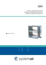
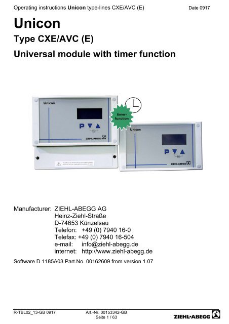
Operating instructions <strong>Unicon</strong> type-lines <strong>CXE</strong>/<strong>AVC</strong> (E) Date 0917<br />
<strong>Unicon</strong><br />
<strong>Type</strong> <strong>CXE</strong>/<strong>AVC</strong> (E)<br />
Universal module with timer function<br />
timerfunction<br />
Manufacturer: ZIEHL-ABEGG AG<br />
Heinz-<strong>Ziehl</strong>-Straße<br />
D-74653 Künzelsau<br />
Telefon: +49 (0) 7940 16-0<br />
Telefax: +49 (0) 7940 16-504<br />
e-mail: info@ziehl-abegg.de<br />
internet: http://www.ziehl-abegg.de<br />
Software D 1185A03 Part.No. 00162609 from version 1.07<br />
R-TBL02_13-GB 0917<br />
Art.-Nr. 00153342-GB<br />
Seite 1 / 63
Operating instructions type-lines <strong>CXE</strong>/<strong>AVC</strong> (E) Date 0917<br />
Contents<br />
1. General................................................................................................................................................. 4<br />
2. Safety measures ................................................................................................................................. 4<br />
3. General description ............................................................................................................................ 5<br />
3.1 Scope of applications ........................................................................................................................................... 5<br />
3.2 Technical data ...................................................................................................................................................... 5<br />
3.3 Versions <strong>Unicon</strong> ................................................................................................................................................... 5<br />
4. Installation........................................................................................................................................... 6<br />
4.1 Wall-mounting, installation in a switching cabinet................................................................................................ 6<br />
4.2 Outdoor installation .............................................................................................................................................. 6<br />
4.3 Installation location for agriculture........................................................................................................................ 6<br />
4.4 Temperature influences during commissioning.................................................................................................... 6<br />
4.5 Potential at control voltage connections............................................................................................................... 6<br />
5. Electrical connections........................................................................................................................ 7<br />
5.1 Mains connection ................................................................................................................................................. 7<br />
5.2 Signal cable (sensor cable).................................................................................................................................. 7<br />
5.3 Signal connection to analog inputs (Analog IN1, Analog IN2, ..) ........................................................................ 7<br />
5.4 Output voltage 0-10 V (Analog OUT1 und Analog OUT2)................................................................................... 7<br />
5.5 Voltage supply for external devices (+24 V, GND) .............................................................................................. 7<br />
5.6 Relay outputs (K1, K2) ......................................................................................................................................... 7<br />
5.7 Digital inputs (D1 .. D5) ........................................................................................................................................ 8<br />
5.8 Connection RS-485 interface for MODBUS......................................................................................................... 8<br />
6. Controls ............................................................................................................................................... 8<br />
6.1 Multipurpose LC display....................................................................................................................................... 8<br />
7. Connection terminals depending on input signal ........................................................................... 9<br />
7.1 External Setpoint / External speed setting in manual operation .......................................................................... 9<br />
8. Mode selection .................................................................................................................................. 10<br />
8.1 Selection of the mode of operation .................................................................................................................... 10<br />
8.2 Menu operation .................................................................................................................................................. 11<br />
8.3 Setting Mode, menu language and motorsetup ................................................................................................. 12<br />
9. Programming..................................................................................................................................... 13<br />
9.1 Speed controller 1.01 ......................................................................................................................................... 13<br />
9.1.1 Basic setting 1.01...................................................................................................................................... 13<br />
9.1.2 Setting for operation 1.01.......................................................................................................................... 13<br />
9.1.3 Menu speed controller 1.01....................................................................................................................... 14<br />
9.2 Temperature control 2.01..2.05.......................................................................................................................... 15<br />
9.2.1 Basic setting 2.01..2.05............................................................................................................................. 15<br />
9.2.2 Settings for operation modes 2.01 .. 2.05 ................................................................................................. 16<br />
9.2.3 Functional diagrams temperature control ................................................................................................. 17<br />
9.2.4 For mode 2.03 temperature controller with additional functions: Signal output 0-10 V ............................ 18<br />
9.2.6 For mode 2.03 Relay output for temperature monitoring.......................................................................... 20<br />
9.3 Pressure control for condensers refirgeration 3.01 .. 3.04................................................................................ 23<br />
9.3.1 Basic setting 3.01 3.02............................................................................................................................. 23<br />
9.3.2 Setting for operation 3.01 .. 3.04............................................................................................................... 24<br />
9.3.3 Menu for pressure control refrigeration 3.01 .. 3.04................................................................................. 25<br />
9.4 Pressure control for ventilation systems 4.01..4.03 ........................................................................................... 27<br />
9.4.1 Basic setting 4.01..4.03............................................................................................................................. 27<br />
9.4.2 Setting for operation modes 4.01 .. 4.03................................................................................................... 28<br />
9.4.3 Menu for pressure control airconditioning 4.01 ..4.02.............................................................................. 29<br />
9.5 Volume control 5.01, 5.02 .................................................................................................................................. 31<br />
9.5.1 Basic setting 5.01, 5.02............................................................................................................................. 31<br />
9.5.2 Setting for operation modes 5.01 and 5.02............................................................................................... 32<br />
TBL02_13-GB 0917<br />
Art.-Nr. 00153342-GB<br />
Seite 2 / 63
Operating instructions type-lines <strong>CXE</strong>/<strong>AVC</strong> (E) Date 0917<br />
9.6 Air velocity control 6.01 ...................................................................................................................................... 35<br />
9.6.1 Basic setting 6.01...................................................................................................................................... 35<br />
9.6.2 Settings for operation modes 6.01 ............................................................................................................ 35<br />
9.6.3 Menu for air velocity control 6.01 .............................................................................................................. 36<br />
10. Menu group Start ............................................................................................................................ 38<br />
11. Menu group Info.............................................................................................................................. 38<br />
12. Controller Setup.............................................................................................................................. 39<br />
12.1 PIN Protection .................................................................................................................................................. 39<br />
12.2 Set protection ................................................................................................................................................... 39<br />
12.3 Save user settings............................................................................................................................................ 39<br />
12.4 Sensor Alarm ON / OFF................................................................................................................................... 40<br />
12.5 Limit.................................................................................................................................................................. 40<br />
12.6 Minimum speed cut off ..................................................................................................................................... 40<br />
12.7 Second Group .................................................................................................................................................. 41<br />
12.8 Reverse action of the control function (actual Value>Set = n+)..................................................................... 41<br />
12.9 Controller configuration (controller type) and controller action ) ...................................................................... 42<br />
13. IO Setup ........................................................................................................................................... 43<br />
13.1 Analog Output A (Analog OUT 1)..................................................................................................................... 43<br />
13.1.1 Function analog output A (Analog OUT 1).............................................................................................. 43<br />
13.1.2 Adjustment analog output A1 und A2 ..................................................................................................... 44<br />
13.2 Functional overview of digital inputs D1 ... D5 ................................................................................................ 45<br />
13.2.1 Enable ON / OFF Funktion 1D.............................................................................................................. 46<br />
13.2.2 External fault Function 2D ...................................................................................................................... 46<br />
13.2.3 Limit ON / OFF Function 3D ................................................................................................................... 47<br />
13.2.4 Switch over E1 / E2 Funktion 4D ........................................................................................................... 47<br />
13.2.5 Set Intern 1 / Set Intern 2 or. Setpoint 1/2 Function 5D ......................................................................... 48<br />
13.2.6 Intern / Extern Function 6D..................................................................................................................... 49<br />
13.2.7 Automatic control / speed manual internal (Menu Speed maunal) Funktion 7D .................................... 50<br />
13.2.8 Reverse action of control function actual value>Set = n+ or actual value>Set = n- Funktion 8D .......... 50<br />
13.3 Inverting analog inputs E1 and E2 ................................................................................................................... 51<br />
13.4 Function and inverting for relay outputs K1 and K2 ......................................................................................... 52<br />
13.5 Network for several divices by MODBUS......................................................................................................... 53<br />
13.5.1 MODBUS - RTU (Remote terminal unit))................................................................................................ 53<br />
13.5.2 External display....................................................................................................................................... 53<br />
13.5.3 Reading and writing parameters ............................................................................................................. 53<br />
14. Limits ............................................................................................................................................... 54<br />
14.1 Limit indication depending on modulation........................................................................................................ 54<br />
14.2 Limit indication depending on setting or sensor signal .................................................................................... 55<br />
14.3 Limit indication depending on offset to Setpoint .............................................................................................. 56<br />
15. Timer (timer) .................................................................................................................................... 57<br />
15.1 Setting the time and date ................................................................................................................................ 57<br />
15.2 Automatic summer/winter time......................................................................................................................... 57<br />
15.3 Timer function................................................................................................................................................... 57<br />
15.4 Enter switching times ....................................................................................................................................... 58<br />
16. Diagnostics menu ........................................................................................................................... 59<br />
17. Enclosure......................................................................................................................................... 60<br />
17.1 Connection diagram ......................................................................................................................................... 60<br />
17.2 Dimension sheet............................................................................................................................................... 61<br />
18. Events .............................................................................................................................................. 62<br />
19. Messages and trouble shooting .................................................................................................... 62<br />
20. Index................................................................................................................................................. 63<br />
TBL02_13-GB 0917<br />
Art.-Nr. 00153342-GB<br />
Seite 3 / 63
Operating instructions type-lines <strong>CXE</strong>/<strong>AVC</strong> (E) Date 0917<br />
1. General<br />
Before installation and start-up, read this manual carefully to ensure a correct use.<br />
Attention! Hazardous area!<br />
Danger owing to electric current or voltage!!<br />
Important information!<br />
• The copyright for these operating instructions remains to ZIEHL-ABEGG AG, Künzelsau.<br />
• The device is constructed in accordance with the current state of technology and the recognised safety regulations.<br />
Nevertheless, use of the device is associated with dangers which may cause death or injury to users or third parties as<br />
well as damage to the system and other objects.<br />
• The device is intended exclusively for the tasks listed in the order confirmation. Any other or extraordinary uses of the<br />
device (unless previously agreed by contract) are considered contrary to regulations. The manufacturer is not liable for<br />
damages resulting from incorrect use. The operating company alone bears the risk.<br />
• To allow for future developments, construction methods and technical data given are subject to alteration. We do not<br />
accept any liability for possible errors or omissions in the information contained in data, illustrations or drawings<br />
provided.<br />
• The controllers are packed ex factory to suit the transport method previously agreed. Always use the original<br />
packaging materials when transporting the controller. When transporting by hand, ensure that personnel possess the<br />
strength required to lift and carry the device. Avoid shocks and impacts to the device. Check the packaging and<br />
controller for damage.<br />
• Store the controller in its original packaging in a dry and weather-proof room. The device must not be exposed to<br />
extreme heat and low temperatures.<br />
2. Safety measures<br />
In the case of a malfunction or a failure of the equipment check all functions with alarms in order to prevent<br />
injury to persons or property. Note possibility of back-up operation.<br />
If used in intensive animal environments, any malfunctions in the air supply must be detected as soon as<br />
possible to prevent the development of a life-threatening situation for the animals. The design and installation<br />
of the system must comply with local regulations and directives. In Germany these include DIN VDE 0100, the<br />
animal protection and the keeping of working animals ordinance and the pig-keeping ordinance etc.<br />
Also note the instructions of AEL, DLG, VdS.<br />
• Apart from the operating instructions and the obligatory regulations to be followed by users relating to accident<br />
prevention, the recognised technical regulations must also be observed (safety and branch-related work as per UVV,<br />
VBG, VDE, etc.).<br />
• These devices are potentially dangerous if they are used incorrectly by untrained personnel or are not implemented<br />
according to their specified use.<br />
• Work on electric components/modules may only be carried out by trained electricians in accordance with<br />
electro-technical regulations (e.g. EN 60204, DIN VDE 0100/0113/0160).<br />
• The contractor or owner must also ensure that the electric systems and equipment are operated and maintained in<br />
accordance with electro-technical regulations. The owner is obliged to ensure that the device are operated in perfect<br />
working order only.<br />
• It is forbidden to carry out work on electrically live parts. The rating given in the enclosure for the device when<br />
open is IP00! It is possible to inadvertently touch components carrying hazardous voltages!<br />
• During operation, the device must be closed or installed in a control cabinet.<br />
• Fuses may only be replaced by new ones and must not be repaired or bypassed. The data for the maximum line fuse<br />
are to be considered absolutely ( Technical data). Use only fuses specified in schematic diagrams.<br />
• The safe isolation from the supply must be checked using a two-pole voltage detector.<br />
• Any faults detected in the electric system/modules/operating equipment must be corrected immediately. If these faults<br />
are not corrected, the device/system is potentially very dangerous. The device/system must therefore not be operated<br />
when it is faulty.<br />
TBL02_13-GB 0917<br />
Art.-Nr. 00153342-GB<br />
Seite 4 / 63
Operating instructions type-lines <strong>CXE</strong>/<strong>AVC</strong> (E) Date 0917<br />
3. General description<br />
3.1 Scope of applications<br />
Universal controller for clean room, refrigeration and air conditioning<br />
Controlled 0-10 V „A1“ (Analog OUT 1) output e.g. for electronic speed controllers of fans<br />
3.2 Technical data<br />
<strong>Type</strong> Part.No line voltage internal device fuse Weight<br />
<strong>CXE</strong>/<strong>AVC</strong> 320006 T 400 mA (5x20 mm) 1.05 kg<br />
1~ 110 .. 277 V (-15 % bis +10 %), 50/60 Hz Art.Nr. 00153002<br />
<strong>CXE</strong>/<strong>AVC</strong>E 320008<br />
0.85 kg<br />
<strong>CXE</strong>/<strong>AVC</strong><br />
320007 2~ 208 .. 415V (-15 % bis +10 %), 50/60 Hz T 400 mA (6,3 x 32mm)<br />
Art.Nr. 00153840<br />
1.05 kg<br />
◦ Input resistance for sensor or signal set for the rotational speed:<br />
- for 0-10 V input: R i >100 kΩ / - bei Eingang 4-20 mA: R i = 100 Ω<br />
◦ Voltage supply e.g. for sensors +24 V ±20 %, I max 120 mA (for connection to an external AXG terminal<br />
minus ca. 50 mA)<br />
◦ Output (0-) 10 V, I max 10 mA (short-circuit-proof)<br />
◦ Heat dissipation approx. 6.5 W<br />
◦ Max. line fuse 10 A<br />
◦ The clock is buffered and has a 2-3 day reserve<br />
◦ Max. permissible ambient temperature 40° C<br />
◦ Min. permissible ambient temperature 0° C (if mains voltage is not switched off up to -20°C)<br />
◦ Permissible rel. humidity 85 % no condensation<br />
◦ Interference emission EN 61000-6-3<br />
◦ Interference immunity EN 61000-6-2<br />
3.3 Versions <strong>Unicon</strong><br />
<strong>Type</strong> <strong>CXE</strong>/<strong>AVC</strong> Housing version IP54 for wall mounting<br />
<strong>Type</strong> <strong>CXE</strong>/<strong>AVC</strong>E for panel mounting (IP54 mounted)<br />
TBL02_13-GB 0917<br />
Art.-Nr. 00153342-GB<br />
Seite 5 / 63
Operating instructions type-lines <strong>CXE</strong>/<strong>AVC</strong> (E) Date 0917<br />
4. Installation<br />
4.1 Wall-mounting, installation in a switching cabinet<br />
◦ For <strong>CXE</strong>/<strong>AVC</strong> Housing version for wall mounting<br />
Assemble the device on a clean and stable base. Do not distort during assembly! Use the appropriate mounting<br />
devices for proper installation of the unit!<br />
◦ For <strong>CXE</strong>/<strong>AVC</strong>E for panel mounting<br />
The installation cutout of the controller amounts to 206 x 118 mm ( dimensions). Bring the controller into the<br />
installation cutout and hang up you the enclosed clamps laterally. Subsequently, you screw the threaded rods with a<br />
screwdriver against the housing.<br />
◦ Do not mount equipment on vibrating base!<br />
◦ Install the device away from transport routes. However, ensure however that the device is still easily accessible!<br />
◦ Cable ducts must remain freely accessible!<br />
◦ Protect the device from direct exposure to sunlight!<br />
◦ The device is designed for vertical installation A reclined installation is only permissible after consultation with the<br />
manufacturer.<br />
4.2 Outdoor installation<br />
Outdoor installation is possible up to -20°C when the controller supply is not switched off.<br />
Installation must be protected from the effects of weather as much as possible, including protection from direct sunlight!<br />
4.3 Installation location for agriculture<br />
In order to avoid damage caused by ammoniac vapours (NH 3 ), the controller shall not be installed in the stable, but<br />
rather in an outhouse wherever possible.<br />
4.4 Temperature influences during commissioning<br />
Avoid condensation in the controller and hence functional faults attributable to condensation by storing the controller at<br />
room temperature!<br />
4.5 Potential at control voltage connections<br />
The control voltage connections (
Operating instructions type-lines <strong>CXE</strong>/<strong>AVC</strong> (E) Date 0917<br />
5. Electrical connections<br />
5.1 Mains connection<br />
Power from the mains is connected to terminals: PE, L1 and N. Here, it must be strictly observed that the mains voltage<br />
lies within the allowable tolerance specifications ( General description: Technical data and nameplate affixed to the<br />
side).<br />
The supply voltage has to correspond to DIN EN 50160!<br />
5.2 Signal cable (sensor cable)<br />
Pay attention to sufficient distance from powerlines and motor wires to prevent interferences.<br />
The control cables may not be longer than 30 m. Screened control cables must be used when the cable length is longer<br />
than 20 m. When using a screened cable, the screen must be connected to the protective conductor at one end, i.e. only<br />
at the control unit (as short and of as low an inductance as possible!).<br />
5.3 Signal connection to analog inputs (Analog IN1, Analog IN2, ..)<br />
The controller can work with 2 analog inputs, dependent on the type of signals must the appropriate terminals<br />
connected.<br />
Signal type<br />
Connection terminals<br />
Input 1 for Temperature sensor TF..<br />
Input 2 for Temperature sensor TF..<br />
Input 1 for 4..20mA (0..20mA)<br />
Input 2 for 4..20mA (0..20mA)<br />
Input 1 for 0-10 V<br />
Input 2 for 0-10 V<br />
7 – 8 (to pay attention to no polarity)<br />
9 - 10 (to pay attention to no polarity)<br />
11 - *12 (with Two-wire-technology)<br />
13 - *14 (with Two-wire-technology<br />
15 (+) - 16 (GND)<br />
17 (+) - 18 (GND)<br />
Ensure correct polarity when connecting; a 24 V DC power supply is integrated for sensors.<br />
*For sensors in two-wire-technology (4-20 mA signal), the connection is made on the +24 V and terminals „11“ (Input 1)<br />
or “13“ (Input 2) the GND terminal is omitted.<br />
For three wire technology connection to GND terminal is necessary (terminals 8,10,16,18)<br />
The connection is independent of the programmed operating mode and from the sensor signal employed ( Presets of<br />
the selected operating mode).<br />
5.4 Output voltage 0-10 V (Analog OUT1 und Analog OUT2)<br />
Analog output 1 (Analog OUT 1) is pre-programmed control outpute.g. for controlling a speed controller for fans.<br />
Connection to terminal „A“ - „GND“ = Analog OUT (I max 10 mA)<br />
output A1 +<br />
0..10 V GND<br />
e.g. <strong>Ziehl</strong>-<strong>Abegg</strong> speed controller<br />
1~ PAE10-M, PASTE6/10<br />
3~ PKDT, PKDM, PXDM, FXDM<br />
EC EATE, ETXD<br />
0-100 %<br />
Analog output 2 (Analog OUT 2) is pre-programmed for contsant voltage +10 V. E.g. supply for external potentiometer<br />
connection to terminals „A2“ - „GND“ = Analog OUT 2 (I max 10 mA)<br />
Both 0-10 V analog outputs can be allocated with various functions (IO Setup: Analog output A1 or A2).<br />
5.5 Voltage supply for external devices (+24 V, GND)<br />
A voltage supply is integrated for external devices, e.g., for a sensor.<br />
Terminal +24 V Output voltage tolerance ±20 %.<br />
Max. load current 120 mA (for connection to an external AXG terminal minus ca. 50 mA)<br />
During an overload or short-circuit (24 V ↔ GND), the control voltage (and thus the controller) is disconnected<br />
(Multifuse). Automatic start after elimination of the cause of error<br />
5.6 Relay outputs (K1, K2)<br />
Various functions can be allocated to the relay outputs K1 and K2<br />
( IO Setup: Function and inversion of the relay outputs). Max. contact load 5A / 250 V AC<br />
Connection of the floating contacts of relay K1 to the terminals 1, 2, 3<br />
Connection of the floating contacts of relay K2 to the terminals 4, 5, 6<br />
TBL02_13-GB 0917<br />
Art.-Nr. 00153342-GB<br />
Seite 7 / 63
Operating instructions type-lines <strong>CXE</strong>/<strong>AVC</strong> (E) Date 0917<br />
5.7 Digital inputs (D1 .. D5)<br />
Various functions can be allocated to the digital inputs D1 ..D5<br />
( IO Setup: Functions summary of the digital inputs).<br />
Activation via floating contacts (a low voltage of ca. 24 V DC is connected).<br />
Never apply external voltage to the digital inputs!<br />
5.8 Connection RS-485 interface for MODBUS<br />
The device comes equipped via a RS-485 interface for networking via a MODBUS. The data connection lead is<br />
connected to D+, D- and GND.<br />
The data connector spring-loaded contact is suitable for solid conductors of up to 0.5 mm 2 cross-section or 0.8 mm<br />
diameter. The stripped lead makes contact by itself upon insertion. The orange colored latch only needs to be pushed in<br />
the case of smaller cross-sections or when detaching the connections.<br />
Examples:<br />
You must ensure correct connection; i.e. „D+“ must also be connected on the following devices to „D+“. The<br />
same applies to „D-“.<br />
In addition, a GND connection must be established, as dissimilar potential (over 10 V!) will lead to the<br />
destruction of the RS-485 interface (e.g. lightning).<br />
The data line must be conducted from one device into the next. To do this, two connectors are available in<br />
each device. No other type of wiring is allowed.<br />
Always use only two wires of one lead for the connection.<br />
When using telephone flex with four cable cores, we recommend the following allocation:<br />
“D+“ = red “D-“ = black “GND“ = white<br />
<strong>Unicon</strong><br />
<strong>Unicon</strong><br />
MODBUS<br />
MODBUS<br />
A maximum of 247 network users can be connected to the data bus .<br />
6. Controls<br />
6.1 Multipurpose LC display<br />
1 Moon-Symbol for set point 2<br />
2 Alarm-Symbol (fault indication)<br />
3 Fire-Symbol (heating operation)<br />
4 Antenna-Symbol (Remote-Control active)<br />
5 STOP-Symbol (enable)<br />
6 Bargraph (intern control output)<br />
7 Text line 3 figures (display unit, etc.)<br />
8 Text line 16 figures (display text menu.)<br />
9 Numeric display 5 digit<br />
9<br />
1 2 3 4 5 6<br />
A B C<br />
7<br />
8<br />
A P-key (program key, open menu)<br />
B arrow -down-key (Menu down, reduce value)<br />
C arrow-up-key (Menu up, increase value)<br />
D<br />
D ESC-key combination (↑ + ↓)<br />
Escape, leave menu)<br />
TBL02_13-GB 0917<br />
Art.-Nr. 00153342-GB<br />
Seite 8 / 63
Operating instructions type-lines <strong>CXE</strong>/<strong>AVC</strong> (E) Date 0917<br />
7. Connection terminals depending on input signal<br />
Dependet ont the type of signal must the appropriate terminals connected. If necessary configuration of sensors<br />
in menu „E1 Analog IN“ or. „E2 Analog IN“ .<br />
Analog IN 1 „E1“<br />
Signal 0-10 V<br />
+<br />
15<br />
10 V<br />
21<br />
16 22<br />
T<br />
Signal 0-10 V<br />
Sensor TF..(KTY)<br />
7<br />
8<br />
+<br />
Sensor MBG-30I<br />
4-20 mA<br />
11<br />
12<br />
24 V<br />
DC<br />
16<br />
T<br />
24 V<br />
DC<br />
Sensor DSG..<br />
0-10 V<br />
14<br />
+<br />
15<br />
16<br />
T<br />
Sensor MAL1/10<br />
0-10 V<br />
24 V<br />
DC<br />
14<br />
+<br />
15<br />
16<br />
T<br />
1 k<br />
3<br />
(gn/GN)<br />
MBG-30I<br />
1<br />
(br/BN)<br />
br<br />
BN<br />
ge<br />
YE<br />
DSG..<br />
ws<br />
WH<br />
1 3<br />
MAL..<br />
2<br />
+<br />
11<br />
12<br />
16<br />
T<br />
Signal 0-20 mA<br />
(4-20 mA)<br />
Analog IN 2 „E2“ for modes with two sensors<br />
9<br />
+<br />
13<br />
10<br />
14<br />
24 V<br />
DC<br />
16<br />
T<br />
3<br />
(gn/GN)<br />
MBG-30I<br />
1<br />
(br/BN)<br />
7.1 External Setpoint / External speed setting in manual operation<br />
External Setpoint or external manual operation is possible by 0-10 V (0-20 mA, 4-20 mA) Signal at terminals „E2" and<br />
„GND". Place internal Jumper E2.1 and E2.2 for Analog IN 2 in correct position. Configuration in base setup. For<br />
Potentiometer Analog OUT 1 (terminal „A“) program to function 1A = +10 V (like factory setting IO Setup). If a second<br />
sensor is connected at input 2, external Setpoint or speed setting in manual operation is possible with additional modul<br />
“ZmodulB“ (input E3).<br />
21 17<br />
+10V E2<br />
18<br />
Signal 0-10 V<br />
1k<br />
External Setpoint via external signal instead of „Setpoint 1“<br />
The „External Setpoint“ function must be activated in base setup 1E for E2 function;<br />
The active external Setpoint value is displayed in the info menu group.<br />
External speed setting in manual operation<br />
The „External manual operation“ function must be activated in the basic settings 2E for E2 function. Switchover between<br />
settings on the device and external manual operation via the digital input or imer ( IO Setup: Internal / External or timer).<br />
TBL02_13-GB 0917<br />
Art.-Nr. 00153342-GB<br />
Seite 9 / 63
Operating instructions type-lines <strong>CXE</strong>/<strong>AVC</strong> (E) Date 0917<br />
8. Mode selection<br />
8.1 Selection of the mode of operation<br />
Simple installation is possible through the selection of the preprogrammed mode of operation. This determines the basic<br />
function of the device; factory setting 1.01 = speed controller (activation via 0-10 V signal).<br />
The controller configuration is automatically carried out during selection of the application related mode of operation. The<br />
factory presets in accordance with the mode of operation are based on many years of experience, which is suitable for<br />
many applications. Under special circumstances, these can be individually adapted ( Controller Setup: Controller<br />
Configuration).<br />
The purpose of the device is to reach and maintain the target values set. To accomplish this, the measured actual value<br />
(sensor value) is compared with the adjusted target value, and the controlled value (modulation) is deduced from this.<br />
Mode<br />
Signal or Sensor<br />
(input)<br />
Function<br />
1.01 Signal 0-10 V( E1) Speed controller, two step operation (factory setting)<br />
2.01 Sensor TF..(E1)<br />
Temperature control airconditioning and refrigeration (preset set-point 20.0 °C,<br />
P-band 5K)<br />
2.02 Sensor TF..(E1)<br />
Temperature control depending on outdoor temperature (preset set-point 5.0 °C, - P-<br />
band 20 K<br />
2.03 Sensor TF..(E1) Temperature control with additional functions (shutter and heating)<br />
1x Sensor TF..(E1)<br />
2.04<br />
1x Sensor TF..(E2)<br />
Temperature control with two sensors, comparison or average<br />
1x Sensor TF..(E1)<br />
2.05<br />
1x Sensor TF..(E2)<br />
Temperature control with two sensors differential temperature<br />
3.01 Sensor MBG.. (E1) Pressure control condensers (refrigeration)<br />
3.02 Sensor MBG..(E1) Pressure control for condensers with input for refrigerant<br />
3.03<br />
3.04<br />
1x Sensor MBG..(E1)<br />
1x Sensor MBG..(E2)<br />
1x Sensor MBG..(E1)<br />
1x Sensor MBG..(E2)<br />
Pressure control for two circuit condensers<br />
Pressure control for two circuit condensers with input for refrigerant<br />
4.01<br />
4.02<br />
5.01<br />
5.02<br />
Sensor DSG..(E1)<br />
1x Sensor DSG..(E1)<br />
1x Sensor TF..(E2)<br />
Sensor DSG..(E1)<br />
1x Sensor DSG..(E1)<br />
1x Sensor TF..(E2)<br />
Pressure control for ventilation systems<br />
Pressure control depending on outdoor temperature<br />
Volume control (constant) for ventilation systems<br />
Volume control with setpoint depending on outdoor temperature<br />
6.01 Sensor MAL.. (E1) Air velocity control<br />
TBL02_13-GB 0917<br />
Art.-Nr. 00153342-GB<br />
Seite 10 / 63
Operating instructions type-lines <strong>CXE</strong>/<strong>AVC</strong> (E) Date 0917<br />
8.2 Menu operation<br />
Display after turning on the mains voltage<br />
Switch-over between Fanlevel and Start or actual value with the key shortcut for Escape (Esc = ↑ + ↓).<br />
Example for mode 1.01 language English<br />
+<br />
= Esc<br />
One reaches the menu item START by pushing the P key.<br />
One moves up and down within the menu group using the<br />
arrow keys.<br />
One returns to the menu group using the ESC (↑ + ↓)<br />
shortcut keys.<br />
Selection of the menu group to the right through the down<br />
key, to the left through the up key.<br />
The menu groups consist of one area for the user (user<br />
menu) and one area for installation (service).<br />
The service area can be protected against unauthorized<br />
access by using a PIN.<br />
In order to simplify the initial start-up operation, the service<br />
level is enabled at first (i.e., not protected by the PIN 0010,<br />
see Controller Setup, PIN protection = OFF).<br />
Userlevel<br />
PIN<br />
Servicelevel<br />
If PIN protection is activated (ON), the service menu remains<br />
enabled after input of PIN 0010 as long as one is pressing<br />
keys. If no keys are pressed for ca. 15 minutes, the PIN is<br />
automatically erased, i.e. the service level is blocked.<br />
After installation of the device has been carried out, PIN protection should be activated!<br />
TBL02_13-GB 0917<br />
Art.-Nr. 00153342-GB<br />
Seite 11 / 63
Operating instructions type-lines <strong>CXE</strong>/<strong>AVC</strong> (E) Date 0917<br />
8.3 Setting Mode, menu language and motorsetup<br />
..<br />
User level Service level<br />
PIN0010<br />
..<br />
..<br />
..<br />
..<br />
..<br />
..<br />
..<br />
If necessary select menu language<br />
(factory default - English)<br />
Selection mode of operation<br />
(factory setting 1.01 = speed controller)<br />
Caution! When saving the operating mode, the respective<br />
preset factory operating-mode setting is loaded. That means,<br />
the settings you have made, e.g., in „Motor setup“ are lost. An<br />
exception: the menu language setting remains preserved.<br />
TBL02_13-GB 0917<br />
Art.-Nr. 00153342-GB<br />
Seite 12 / 63
Operating instructions type-lines <strong>CXE</strong>/<strong>AVC</strong> (E) Date 0917<br />
9. Programming<br />
9.1 Speed controller 1.01<br />
9.1.1 Basic setting 1.01<br />
9.1.2 Setting for operation 1.01<br />
↓P ↑ ESC<br />
↓P ↑ ESC<br />
↓ ↑<br />
Factory setting Mode 1.01<br />
↓ ↑<br />
Manual speed setting<br />
Set Internal 1<br />
↓ ↑<br />
Factory setting 0-10 V<br />
Selection : 0-20 mA, 4-20 mA,<br />
Bus<br />
Inverting in IO Setup<br />
↓ ↑<br />
Set internal 2<br />
Swich over1/2 by external contact<br />
Analog input 2 „E2“ factory set at<br />
OFF<br />
↓ ↑<br />
Minimal speed<br />
0 - 100 %<br />
• For operation with a second signal and switch over via<br />
floating contact<br />
( IO Setup) set to function 1 E.<br />
• For operation with a second signal and automatic control<br />
at the higher level. Set E2 Funktion to 4E.<br />
↓ ↑<br />
↓ ↑<br />
Maximal speed<br />
100% - Min.<br />
ON = (factory setting)<br />
speed setting by external signal<br />
OFF =<br />
Set internal 1<br />
Diagram default signal and output voltage<br />
Idealized principle diagram<br />
0-100% = 0-10V<br />
100 %<br />
Min. 0 % Max. = 100 %<br />
Min. = 35 % Max. = 85 %<br />
50 %<br />
Min.<br />
Signal<br />
0 1 2 3 4 5 6 7 8 9 10 0-10 V<br />
10 9 8 7 6 5 4 3 2 1 0 10-0 V<br />
0 2 4 6 8 10 12 14 16 18 20 0-20 mA<br />
20 18 16 14 12 10 8 6 4 2 0 20-0 mA<br />
4 5,6 7,2 8,8 10,4 12 13,6 15,2 16,8 18,4 20 4-20 mA<br />
20 18,4 16,8 15,2 13,6 12 10,4 8,8 7,2 5,6 4 20-4 mA<br />
TBL02_13-GB 0917<br />
Art.-Nr. 00153342-GB<br />
Seite 13 / 63
Operating instructions type-lines <strong>CXE</strong>/<strong>AVC</strong> (E) Date 0917<br />
9.1.3 Menu speed controller 1.01<br />
Start<br />
Setting Info<br />
Events<br />
Timer Limits IO Setup<br />
Controller Setup Base setup<br />
Parameter<br />
Factory<br />
setting User Setting<br />
PIN Input .----<br />
Language<br />
GB<br />
Reset<br />
OFF<br />
Mode 1.01 Only Display<br />
<strong>Unicon</strong> 1.06<br />
Fanlevel 0%<br />
Set external1 0%<br />
Time 12:06<br />
Date 18.07 05<br />
Set Intern 1 80%<br />
Set Intern 2 .-----<br />
Min. Speed 0%<br />
Max. Speed 100%<br />
Set external 1<br />
ON<br />
External Error *<br />
*<br />
*<br />
INSTALLATION<br />
Mode 1.01<br />
E1 Analog IN 0-10V E2 Function<br />
E2 Function OFF 1E E1/E2 switch over<br />
E2 Analog IN .---- 4E E1/E2 autom. control to higher value<br />
PIN Protection OFF<br />
Set protection<br />
OFF<br />
Save User Setup OFF<br />
Limit .----<br />
ON Value Group 2 .----<br />
nminm at Group 2 .----<br />
A1 Function<br />
2A<br />
A1 min.<br />
0.0 V<br />
A1 / A2 Function<br />
A1 max. 10.0 V 1A Constant voltage + 10V<br />
A1 Inverting OFF 2A proportional modulation<br />
A2 Function 1A 3A proportional signal E1<br />
A2 min. 0.0 V 4A proportional signal E2<br />
A2 max. 10.0 V 5A Group control<br />
A2 Inverting<br />
OFF<br />
D1 Function<br />
OFF<br />
D1..D5 Funktion<br />
D1 Inverting .----- 1D Enable ON / OFF<br />
D2 Function OFF 2D External fault<br />
D2 Inverting .---- 3D Limit ON / OFF<br />
D3 Function OFF 4D Switch over Singnal E1/E2<br />
D3 Inverting .---- 5D switch over Intern 1 / 2<br />
D4Function OFF 6D switch over:Set Intern / Extern<br />
D4 Inverting .----<br />
D5 Function<br />
OFF<br />
K1 / K2 Function<br />
D5 Inverting .---- 1K Operation indication<br />
E1 Inverting OFF 2K Fault indication<br />
E2 Inverting .---- 3K external fault<br />
K1 Function 1K 4K Limit modulation<br />
K1 Inverting OFF 5K Limit E1<br />
K2 Function 2K 6K Limit E2<br />
K2 Inverting OFF 8K Group control<br />
BUS Address 247<br />
Level. Function OFF<br />
Level min. .---- Limits (Lmt. Function)<br />
Level max. .---- 1L Indication with centralized fault<br />
Level Delay .---- 2L Indication as message<br />
Lmt E1 Function OFF<br />
Lmt E1 min. .----<br />
Lmt E1 max. .----<br />
Lmt E1 Hyst. .----<br />
Lmt E1 Delay .----<br />
Lmt E2 Function .----<br />
Lmt E2 min. .----<br />
Lmt E2 max. .----<br />
Lmt E2 Hyst. .----<br />
Lmt E2 Delay .----<br />
Time 13:25<br />
Date 18.07 05<br />
Summertime Auto. OFF<br />
Timer Function OFF<br />
Mon<br />
Mon ON1 .--:--<br />
Mon OFF1 .--:--<br />
Mon ON2 .--:--<br />
Mon OFF2 .--:--<br />
Diagnostics Menu see chapter 16<br />
TBL02_13-GB 0917<br />
Art.-Nr. 00153342-GB<br />
Seite 14 / 63
Operating instructions type-lines <strong>CXE</strong>/<strong>AVC</strong> (E) Date 0917<br />
9.2 Temperature control 2.01..2.05<br />
9.2.1 Basic setting 2.01..2.05<br />
↓P ↑ ESC<br />
Function analog Input 2<br />
↓ ↑<br />
↓ ↑<br />
In all group 2 operating modes<br />
(2.01, 2.02, 2.03, ....)<br />
E1 analogue input IN factory set<br />
to „TF“<br />
• External setpoint = Function 1E<br />
by external signal (0-10 V) instead of<br />
„Set point 1“<br />
For sensor type „E1 TF“..: 0-10 V ^ -27°C..+75.0°C<br />
For sensors with active signal:<br />
0-10 V ^ 0-100 % sensor measuring range<br />
Alternative selection signal: 0-10 V, 0-20 mA, 4-20 mA,<br />
jumper accordingly inserted. The sensor<br />
measurement-range must be entered in order to<br />
correctly display the actual value. Example with a 0-10<br />
V sensor and 0-100° C measurement range<br />
• External manual operation via external signal (0-10V) =<br />
function 2E<br />
Switch over between settings on the device and external<br />
manual operation via digital input ( IO Setup).<br />
• Measurement value = function 7E<br />
e.g. for limit indication, display in Info menu “E2 actual”<br />
Initial value measuring range<br />
Final value measuring range<br />
Decimal places<br />
display unit<br />
Sensor calibration with calibrated<br />
comparison device<br />
• Modes with two sensors<br />
The function is automatically jointly programmed in operating<br />
modes using 2 sensors. The second analog input is thus<br />
allocated and additional function allocations are not possible.<br />
2.04<br />
E2 Function at 4E preprogrammed = comparison value with<br />
control to higher temperature.<br />
alternative: average of 2 measuring points for this must be<br />
reprogrammed on function 3E preprogrammed sensor type<br />
TF..<br />
2.05<br />
E2 Function at 5E preprogrammed = regulation on<br />
difference temperature between sensor 1 and sensor 2.<br />
Preprogrammed sensor type TF..<br />
TBL02_13-GB 0917<br />
Art.-Nr. 00153342-GB<br />
Seite 15 / 63
Operating instructions type-lines <strong>CXE</strong>/<strong>AVC</strong> (E) Date 0917<br />
9.2.2 Settings for operation modes 2.01 .. 2.05<br />
2.01<br />
Temperature control<br />
2.02<br />
Temperature control depending on outdoor temperature<br />
2.03<br />
Temperature control with additional functions (heating, shutter, temp. monitoring)<br />
2.04<br />
Temperature control with two sensors.<br />
- comparison with control to higher value „E2 Function“ set<br />
to comparison „4E“. display during operation: "Control value".<br />
- Alternative: Average calculation of 2 measuring places Display during operation:<br />
"Average E1 / E2 („E2 Function“ set to „3E“ )<br />
2.05<br />
Temperature control with 2 sensors, regulation on difference temperature<br />
display during operation: "Value of E1 - E2 in K, E1 = reference temperatur, E2 causes positiv (E2E1) difference<br />
↓P ↑ ESC<br />
Setpoint 1<br />
Setting range: -27.0 .. 75°C<br />
↓ ↑<br />
↓ ↑<br />
↓ ↑<br />
↓ ↑<br />
Setpoint 2<br />
„Setpoint 2“ (factory setting OFF)<br />
e.g. reduced value for night operation. Switch over by digital input.<br />
(As long as no allocation has been carried out: Display: - - - - - IO Setup).<br />
Pband (Control range)<br />
The control response can be adjusted to the system conditions<br />
- small control range = greater amplification and shorter control times<br />
- big control range = longer control times and higher controller stability<br />
Setting range: 0-102,0 K<br />
Min. Speed „n-min“ (minimum output voltage )<br />
If required setting of a minimum output voltage e. g. basic speed (minimum airflow rate) of fans.<br />
Setting range: 0 % up to 100 % (or Max. speed).<br />
Max. Speed „n-max“ (maximum output voltage)<br />
If required setting of a maximum output voltage, e. g. speed limiter.<br />
Setting range: 100 % down to „Min speed“.<br />
↓ ↑<br />
Manual mode<br />
OFF = automatic control as function of the set parameters<br />
ON = automatic control without function, speed setting in menu “Speed manual“<br />
↓ ↑<br />
Speed manual<br />
Manual speed setting without influence by the external signal<br />
Activation by menu „Manual mode“ or external contact at digital input ( IO Setup).<br />
For information about deactivated regulation the adjusted value for manual<br />
speed is indicated alternating with the actual value<br />
TBL02_13-GB 0917<br />
Art.-Nr. 00153342-GB<br />
Seite 16 / 63
Operating instructions type-lines <strong>CXE</strong>/<strong>AVC</strong> (E) Date 0917<br />
9.2.3 Functional diagrams temperature control<br />
Example 1:<br />
Temperature control in factory setting „Cooling function“ (Controller Setup: Ist>Soll= n+ ON)<br />
(Idealized principle diagram)<br />
1<br />
Modulation<br />
100 %<br />
Min.= 0 % Max. = 100 %<br />
Min. = 35 % Max = 85 %<br />
50 %<br />
Istwert / Actual<br />
20 °C<br />
Sollwert<br />
Setpoint<br />
10 K<br />
Regelbereich<br />
Pband<br />
30 °C<br />
Example 2 :<br />
Temperature control in „Heating function“ (Controller Setup: Ist>Soll= n+ OFF)<br />
(Idealized principle diagram)<br />
2<br />
Modulation<br />
100 %<br />
Max.<br />
Min. 0 % Max. = 100 %<br />
50 %<br />
Min.<br />
Min. = 35 % Max. = 85 %<br />
10 °C<br />
10 K<br />
Regelbereich<br />
Pband<br />
20 °C<br />
Sollwert<br />
Setpoint<br />
Istwert / Actual<br />
TBL02_13-GB 0917<br />
Art.-Nr. 00153342-GB<br />
Seite 17 / 63
Operating instructions type-lines <strong>CXE</strong>/<strong>AVC</strong> (E) Date 0917<br />
9.2.4 For mode 2.03 temperature controller with additional functions: Signal output 0-10 V<br />
The 0-10 V output signal can, e.g., be used for triggering a shutter or heating.<br />
↓ ↑<br />
The target value for this output is the target value (Setpoint) for the ventilation ±offset setting.<br />
Adjustment range ±10 K relative to the active Setpoint.<br />
Example for triggering a shutter servomotor:<br />
At factory setting „0 K“ = synchronous operation.<br />
The analog output is factory set to increasing activation during increasing temperature.<br />
Reprogramming to „Heating function“, i.e., increasing modulation during decreasing<br />
temperature is possible ( IO Setup).<br />
Pband = separately adjustable range of control (P-band) for 0-10 V output<br />
↓ ↑<br />
Min Analog Out = Minimal output voltage, setting range 0-100 % = 0-10 V<br />
↓ ↑<br />
Max. Analog Out = Maximal output voltage, setting range 100-0 % = 10-0 V<br />
Example for signal out 0-10 V<br />
- Setpoint ventilation 25°C<br />
- Offset -5 K<br />
- Pband 10 K<br />
A2 10 V<br />
100 %<br />
Max. Analog Out<br />
Min. = 0% Max. = 100 %<br />
Min. = 35 % Max. = 85 %<br />
50 %<br />
Min. Analog Out<br />
+/- Offset = 20 °C<br />
Sollwert<br />
Setpoint<br />
10 K<br />
Regelbereich<br />
Pband<br />
30 °C<br />
Istwert / Actual<br />
TBL02_13-GB 0917<br />
Art.-Nr. 00153342-GB<br />
Seite 18 / 63
Operating instructions type-lines <strong>CXE</strong>/<strong>AVC</strong> (E) Date 0917<br />
9.2.5 For mode 2.03 Relay output for Heating or Cooling<br />
Offset Digital Out = Offset for relay output (K2 is pre-programmed by the factory )<br />
The relay operating point deviates by the adjusted offset of the Setpoint of the ventilation (if<br />
relay K2 not inverted, terminal „21“-„24“ bridged).<br />
0.0 K set, i.e. heating „ON“ when: actual value = Setpoint<br />
During negative offset value heating „ON“ when: actual value = Setpoint - offset<br />
During positive offset value heating „ON“ when: actual value = Setpoint + offset<br />
The switching hysteresis of the relay is set to 1 K at factory Hyst. Digital Out.<br />
Example 1<br />
Temperature variation with factory setting 9 K in IO Setup e. g. for controlling a Heating<br />
If the ambient temperature is lower than the set operating point, the heating remains switched on. If the ambient<br />
temperature exceeds the set operating point of the heating by 2 K, the heating is switched off. I.e., the release point is<br />
situated at the hysteresis value over the operating point.<br />
The activated heating is indicated over the fire symbol in the display<br />
Example 2<br />
Temperature variation with reprogramming to 10K in IO Setup, e.g., for activation of the cooling<br />
If the ambient temperature is higher than the set operating point, the cooling remains switched on.<br />
If the ambient temperature falls below the set operating point of the cooling by 2 K, it is switched off. I.e., the OFF point<br />
is situated at the hysteresis value under the ON point.<br />
IO Setup K2 Function for Heating = 9K<br />
Example 1: Setpoint 15°C, Offset +5K, Hysteresis 2 K<br />
Example 1: Setpoint 20°C, Offset -5K, Hysteresis 2 K<br />
[°C]<br />
30<br />
28<br />
26<br />
24<br />
22<br />
20<br />
18<br />
16<br />
14<br />
12<br />
10<br />
ON = 15°C + 5K = 20 °C OFF = 20°C + 2K = 22 °C<br />
1 3 5 7 9 11 13 15 17 19 21 23 25 27 29<br />
[min]<br />
ON<br />
ON<br />
ON<br />
[°C]<br />
30<br />
28<br />
26<br />
24<br />
22<br />
20<br />
18<br />
16<br />
14<br />
12<br />
10<br />
OFF= 15°C + 2K = 17 °C ON= 20°C - 5K = 15 °C<br />
1 3 5 7 9 11 13 15 17 19 21 23 25 27 29<br />
[min]<br />
ON<br />
ON<br />
IO Setup K2 Function for Cooling = 10K<br />
Example 2: Setpoint 15°C, Offset +5K, Hysteresis 2 K<br />
[°C]<br />
30<br />
28<br />
26<br />
24<br />
22<br />
20<br />
18<br />
16<br />
14<br />
12<br />
10<br />
1 3 5 7 9 11 13 15 17 19 21 23 25 27 29<br />
[min]<br />
ON ON ON<br />
OFF= 20°C - 2K = 18 °C<br />
ON= 15°C + 5K = 20 °C<br />
TBL02_13-GB 0917<br />
Art.-Nr. 00153342-GB<br />
Seite 19 / 63
Operating instructions type-lines <strong>CXE</strong>/<strong>AVC</strong> (E) Date 0917<br />
9.2.6 For mode 2.03 Relay output for temperature monitoring<br />
If the set value for the minimum alarm is not reached or the set value for the maximum alarm is exceeded, a message is<br />
generated via the alarm symbol in the display. In addition, „Lmt E1 min“ is displayed alternately with the actual value for<br />
the minimum alarm and Lmt E1 max for the „Maximum alarm“. An external message follows via the factory-assigned K1<br />
relay. (IO Setup : K1 function = 2K)<br />
↓ ↑<br />
Example for display if temperature is falling below setting „Alarm Minimum“<br />
Relay K1 disengages (if not inverted)<br />
1 2 3<br />
K1<br />
Example for display if temperature is exceeding setting „Alarm Maximum“<br />
Relay K1 disengages (if not inverted)<br />
1 2 3<br />
K1<br />
TBL02_13-GB 0917<br />
Art.-Nr. 00153342-GB<br />
Seite 20 / 63
Operating instructions type-lines <strong>CXE</strong>/<strong>AVC</strong> (E) Date 0917<br />
9.2.7 Menu for temperature controller 2.01 ..2.05<br />
S ta r t<br />
C o n tro lle r S e tu p B ase setup<br />
E v e n ts<br />
S e ttin g<br />
In fo<br />
Parameter<br />
factory setting<br />
User Setting<br />
PIN Input .---- .---- .---- .---- .----<br />
Language GB GB GB GB GB<br />
Reset OFF OFF OFF OFF OFF<br />
Mode 2.01 2.02 2.03 2.04 2.05<br />
<strong>Unicon</strong> 1.06 1.06 1.06 1.06 1.06 Only Display<br />
Value E1-E2<br />
-2.4°C<br />
Control value<br />
26.1°C<br />
E1 Actual 30°C 10°C 30.0°C 22.9°C 21.9°C<br />
E2 Actual .----- .----- .----- 26.1°C 24.3°C<br />
Setpoint 1 20.0°C 5.0°C 20.0°C 20.0°C 0.0°C<br />
Fanlevel 0,5 0,25 0,5 1 0<br />
Msco. OFF OFF OFF OFF OFF<br />
Time 12:06 12:06 12:06 12:06 12:06<br />
Date 18.07 05 18.07 05 18.07 05 18.07 05 18.07 05<br />
Setpoint 1 20.0°C 5.0°C 20.0°C 20.0°C 0.0°C<br />
Setpoint 2 .----- .----- .----- .----- .-----<br />
Pband 5.0 K 20.0 K 5.0 K 5.0 K 5.0 K<br />
Min. Speed 0% 0% 0% 0% 0%<br />
Max. Speed 100% 100% 100% 100% 100%<br />
Manual mode OFF OFF OFF OFF OFF<br />
Speed manual 100% 100% 100% 100% 100%<br />
Offset AnalogOut 0.0K<br />
Pband AnalogOut 2.0K<br />
Min. AnalogOut 0%<br />
Max. AnalogOut 100%<br />
OffsetDigitalOut<br />
-1.0K<br />
Hyst.DigitalOut 1.0K<br />
Alarm Minimum<br />
0.0°C<br />
Alarm Maximum<br />
40.0°C<br />
External Error * * * *<br />
Sensor 1 * * * *<br />
INSTALLATION<br />
Mode 2.01 2.02 2.03 2.04 2.05<br />
E1 Analog IN TF TF TF TF TF<br />
E1 Min. .---- .---- .---- .---- .---- 2.01 Temperature control<br />
E1 Max. .---- .---- .---- .---- .----<br />
E1 Decimals .---- .---- .---- .---- .---- 2.02 Temperature control depending on outdoor temperature<br />
E1 unit .---- .---- .---- .---- .----<br />
E1 Offset 0.0K 0.0K 0.0K 0.0K 0.0K 2.03 Temperaturre control with additional functions:<br />
E2 Function OFF OFF OFF 4E 5E Heating, shutter, temp. Monitoring<br />
E2 Analog IN .---- .---- .---- TF TF<br />
E2 Min. .---- .---- .---- .---- .---- 2.04 Temperature control with two Sensors<br />
E2 Max. .---- .---- .---- .---- .---- comparison with control to higher value<br />
E2 Decimals .---- .---- .---- .---- .---- average calculation of 2 measuring places<br />
E2 unit .---- .---- .---- .---- .----<br />
E2 Offset .---- .---- .---- 0.0K 0.0K 2.05 Temperature control of 2 sensors<br />
PIN Protection OFF OFF OFF OFF OFF regulation on difference temperature<br />
Set protection OFF OFF OFF OFF OFF<br />
Save User Setup OFF OFF OFF OFF OFF<br />
E2 Funktion<br />
Alarm Sensors OFF OFF OFF OFF OFF 1E 0-10 V external Setpoint<br />
Limit .---- .---- OFF .---- .---- 2E external manual mode<br />
Msco. OFF OFF OFF OFF OFF 3E Sensor average to E1<br />
ON Value Group2 .---- .---- .---- .---- .---- 4E Sensor comparison to E1<br />
nminm bei Gruppe2 .---- .---- .---- .---- .---- 5E Sensor difference to E1<br />
Val>Set = n+ ON ON ON ON ON 6E Sensor for setpoint lowering<br />
<strong>Type</strong> of control P P P P P only for mode 4.02 and 5.02)<br />
KP 50% 50% 50% 50% 50% 7 E measurement value for indication and display<br />
KI 50% 50% 50% 50% 50%<br />
KD 50% 50% 50% 50% 50%<br />
TI 0% 0% 0% 0% 0%<br />
TBL02_13-GB 0917<br />
Art.-Nr. 00153342-GB<br />
Seite 21 / 63
Operating instructions type-lines <strong>CXE</strong>/<strong>AVC</strong> (E) Date 0917<br />
IO S e tu p<br />
T im e r L im its<br />
2.01 2.02 2.03 2.04 2.05 User Setting<br />
A1 Function 2A 2A 2A 2A 2A<br />
A1 / A2 Function<br />
A1 min. 0.0 V 0.0 V 0.0 V 0.0 V 0.0 V 1 A Constant voltage + 10V<br />
A1 max. 10.0 V 10.0 V 10.0 V 10.0 V 10.0 V 2 A proportional modulation<br />
A1 Inverting OFF OFF OFF OFF OFF 3 A proportional signal E1<br />
A2 Function 1A 1A 6A 1A 1A 4 A proportional signal E2<br />
A2 min. 0.0 V 0.0 V 0.0 V 0.0 V 0.0 V 5 A Group control<br />
A2 max. 10.0 V 10.0 V 10.0 V 10.0 V 10.0 V 6 A only 2.03 cooling<br />
A2 Inverting OFF OFF OFF OFF OFF 7 A only 2.03 Heating<br />
D1 Function OFF OFF OFF OFF OFF<br />
D1 Inverting .----- .----- .----- .----- .-----<br />
D1..D5 Funktion<br />
D2 Function OFF OFF OFF OFF OFF 1 D Enable ON / OFF<br />
D2 Inverting .---- .---- .---- .---- .---- 2 D External fault<br />
D3 Function OFF OFF OFF OFF OFF 3 D Limit ON / OFF<br />
D3 Inverting .---- .---- .---- .---- .---- 4 D Switch over Singnal E1/E2<br />
D4Function OFF OFF OFF OFF OFF 5 D switch over Setpoint 1 / 2<br />
D4 Inverting .---- .---- .---- .---- .---- 6 D switch over:Set Intern / Extern<br />
D5 Function OFF OFF OFF OFF OFF 7 D Controlling / Manual intern<br />
D5 Inverting .---- .---- .---- .---- .---- 8 D switch over:ActualValue>Set=n+/n-<br />
E1 Inverting OFF OFF OFF OFF OFF<br />
E2 Inverting .---- .---- .---- .---- .----<br />
K1..K4 Funktion<br />
K1 Function 1K 1K 1K 1K 1K 1 K Operation indication<br />
K1 Inverting OFF OFF OFF OFF OFF 2 K Fault indication<br />
K2 Function 2K 2K 9K 2K 2K 3 K external fault<br />
K2 Inverting OFF OFF OFF OFF OFF 4 K Limit modulation<br />
BUS Address 247 247 247 247 247 5 K Limit E1<br />
Level. Function OFF OFF OFF OFF OFF 6 K Limit E2<br />
Level min. .---- .---- .---- .---- .---- 7 K Setpoint Offset<br />
Level max. .---- .---- .---- .---- .---- 8 K Group control<br />
Level Delay .---- .---- .---- .---- .---- 9 K only 2.03 heating funktion<br />
Lmt E1 Function OFF OFF 1L OFF OFF 10 K only 2.03 cooling function<br />
Lmt E1 min. .---- .---- 0.0°C .---- .----<br />
Lmt E1 max. .---- .---- 40.0°C .---- .----<br />
Lmt E1 Hyst. .---- .---- 1.0K .---- .----<br />
Lmt E1 Delay .---- .---- 2sec .---- .---- Limits (Lmt. Function)<br />
Lmt E2 Function .---- .---- .---- .---- .---- 1 L Indication with centralized fault<br />
Lmt E2 min. .---- .---- .---- .---- .---- 2 L Indication as message<br />
Lmt E2 max. .---- .---- .---- .---- .----<br />
Lmt E2 Hyst. .---- .---- .---- .---- .----<br />
Lmt E2 Delay .---- .---- .---- .---- .----<br />
Offset Function OFF OFF OFF OFF OFF<br />
Offset 1 .---- .---- .---- .---- .----<br />
Offset 2 .---- .---- .---- .---- .----<br />
Offset Hyst. .---- .---- .---- .---- .----<br />
Offset Delay .---- .---- .---- .---- .----<br />
Time 13:25 13:25 13:25 13:25 13:25<br />
Date 18.07 05 18.07 05 18.07 05 18.07 05 18.07 05<br />
Summertime Auto. OFF OFF OFF OFF OFF<br />
Timer Function OFF OFF OFF OFF OFF<br />
Mon<br />
Mon ON1 .--:-- .--:-- .--:-- .--:-- .--:--<br />
Mon OFF1 .--:-- .--:-- .--:-- .--:-- .--:--<br />
Mon ON2 .--:-- .--:-- .--:-- .--:-- .--:--<br />
Mon OFF2 .--:-- .--:-- .--:-- .--:-- .--:--<br />
Diagnostics Menu see chapter 16<br />
TBL02_13-GB 0917<br />
Art.-Nr. 00153342-GB<br />
Seite 22 / 63
Operating instructions type-lines <strong>CXE</strong>/<strong>AVC</strong> (E) Date 0917<br />
9.3 Pressure control for condensers refirgeration 3.01 .. 3.04<br />
9.3.1 Basic setting 3.01 3.04<br />
Function Analog Input 2<br />
↓P ↑ ESC<br />
↓ ↑<br />
For all Modes in Group 3 (3.01, 3.02, 3.03 ....)<br />
Analog input E1 factory setting to “MBG-30I”<br />
(measuring range 0-30 bar, proportional output 4-20 mA).<br />
Selection sensor: MBG-30I DSF2-25<br />
Alternative selection signal: 0-10 V, 0-20 mA, 4-20 mA,<br />
jumper accordingly inserted. The sensor measurement<br />
range must be entered in order to display the actual value<br />
correctly.<br />
Example: 0-10 V sensor and range 20 bar<br />
Initial value measuring range<br />
Final value measuring range<br />
• External setpoint = Function 1E<br />
by external signal (0-10 V) instead of „Setpoint 1“<br />
0-10 V ^ sensor measuring range<br />
• External manual = function 2E<br />
operation via external signal (0-10V)<br />
Switch over between settings on the device and external<br />
manual operation via digital input<br />
( IO Setup).<br />
• Measurement value = function 7E<br />
e.g. for limit indication, display in Info menu “E2 actual”<br />
• Modes with two sensors<br />
The function is automatically jointly programmed in<br />
operating modes using 2 sensors. The second analog<br />
input is thus allocated and additional function allocations<br />
are not possible.<br />
3.04 + 3.03<br />
E2 Function at 4E preprogrammed = comparison value with<br />
control to higher value (two circuit condensers).<br />
Decimal places<br />
display unit<br />
Sensor calibration with calibrated<br />
comparison device<br />
3.02 and 3.04 operating modes with refrigerant for use with<br />
<strong>Ziehl</strong>-<strong>Abegg</strong> pressure sensor type MBG-30I or DSF2-25<br />
Upon input of the refrigerant, the device automatically<br />
calculates the corresponding temperature for the<br />
measured pressure. The settings for offset, target value<br />
and the controlling range are then carried out in °C or K.<br />
Calculation for relative pressure (differential measurement<br />
of pressure relative to ambient pressure<br />
No further settings are necessary for pressure sensors<br />
from <strong>Ziehl</strong>-<strong>Abegg</strong> model e.g. MBG-30I (measurement<br />
range 0-30 bar). In the case of sensors with other<br />
measurement ranges, the „E1 Min value“ and the „E1 Max<br />
Value“ must be entered in °C. To do this, convert the bar<br />
values for min and max into °C.<br />
Selection refrigerant :<br />
R12 R13 R13b1 R22 R23 R32 R114 R134a R142B<br />
R227 R401 R401A R401B R402 R402A R402B R404A R407A<br />
R407B R407C R500 R502 R503 R507 R717<br />
TBL02_13-GB 0917<br />
Art.-Nr. 00153342-GB<br />
Seite 23 / 63
Operating instructions type-lines <strong>CXE</strong>/<strong>AVC</strong> (E) Date 0917<br />
9.3.2 Setting for operation 3.01 .. 3.04<br />
3.01 Pressure control condensers, Setpoint in bar<br />
3.02 Pressure control for condensers with input for refrigerant, Setpoint in °C<br />
3.03 t w o sensors for dual circuit condenser, automatic regulation to the highest pressure (selection amplifier integrated)<br />
operation display: „Control value“, Setpoint in bar<br />
3.04 t w o sensors for dual circuit condenser with input for refrigerant automatic regulation to the highest pressure<br />
(selection amplifier).<br />
Setpoint in °C , also for different refrigerants suitably there comparison of the temperatures. Display during<br />
operation: „Control value“<br />
↓P ↑ ESC<br />
3.01 and 3.03 setting in bar 3.02 and 3.04 input for refrigerant setting in °C<br />
Setpoint 1 (factory setting 12.0 bar)<br />
Setpoint 1 (factory setting 35.0.°C<br />
Setting range:<br />
Setting range:<br />
in measuring range of sensor<br />
in measuring range of sensor<br />
Setpoint 2<br />
Switch over 1/2 by external contact<br />
( IO Setup<br />
Control range „Pband“<br />
small range = great amplification and<br />
short control time<br />
Big range = longer control times<br />
(higher controller stability)<br />
Minimal speed<br />
0-100 %<br />
Setpoint 2<br />
Switch over 1/2 by external contact<br />
( IO Setup<br />
Control range „Pband“<br />
small range = great amplification and<br />
short control time<br />
Big range = longer control times (higher<br />
controller stability)<br />
Minimal speed<br />
0-100 %<br />
Maximal speed<br />
100% - Min.<br />
Maximal speed<br />
100% - Min.<br />
OFF = automatic control<br />
ON = manual speed setting0 - 100<br />
%<br />
Manual speed setting<br />
0 - 100 % if manual mode = ON<br />
OFF = automatic control<br />
ON = manual speed setting0 - 100<br />
Manual speed setting<br />
0 - 100 % if manual mode = ON<br />
Modulation<br />
100 %<br />
Modulation<br />
100 %<br />
n-min = 0% n-max = 100 %<br />
n-min = 0% n-max = 100 %<br />
50 %<br />
50 %<br />
actual<br />
actual<br />
Setpoint 12 bar<br />
Pband 5 bar<br />
17 bar<br />
Set point 35.0°C<br />
Pband 7 K<br />
42.0 °C<br />
(Idealized prinziple diagram)<br />
(Idealized prinziple diagram)<br />
The factory default presets must be adapted to match the system conditions by a competent person.<br />
TBL02_13-GB 0917<br />
Art.-Nr. 00153342-GB<br />
Seite 24 / 63
Operating instructions type-lines <strong>CXE</strong>/<strong>AVC</strong> (E) Date 0917<br />
9.3.3 Menu for pressure control refrigeration 3.01 .. 3.04<br />
S ta r t<br />
Events S e ttin g<br />
Info<br />
B ase setup<br />
C o n tr o lle r S e tu p<br />
Parameter<br />
factory setting<br />
User Setting<br />
PIN Input .---- .---- .---- .----<br />
Language GB GB GB GB<br />
only display<br />
Reset OFF OFF OFF OFF<br />
Mode 3.01 3.02 3.03 3.04<br />
<strong>Unicon</strong> 1.06 1.06 1.06 1.06<br />
Control value 10.91 bar 22.6°C<br />
E1 Actual 10.00 bar 19.5°C 9.95 bar 19.4 °C<br />
E2 Actual .----- .----- 10.91bar 22.5°C<br />
Setpoint 1 12.00 bar 35.0°C 12.00 bar 35.0°C<br />
Fanlevel 0 0 0 0<br />
Msco. OFF OFF OFF OFF<br />
Time 12:06 12:06 12:06 12:06<br />
Date 18.07 05 18.07 05 18.07 05 18.07 05<br />
Setpoint 1 12.00 bar 35.0°C 12.00 bar 35.0°C<br />
Setpoint 2 .----- .----- .----- .-----<br />
Pband 5.0 bar 7.0 K 5.00 bar 7.0 K 3.01 Pressure control condensers<br />
Min. Speed 0% 0% 0% 0% Setpoint in bar<br />
Max. Speed 100% 100% 100% 100%<br />
Manual mode OFF OFF OFF OFF 3.02 Pressure control condensers with input for refrigerant<br />
Speed manual 100% 100% 100% 100% Setpoint in °C<br />
External Error * * * *<br />
Sensor 1 * * * * 3.03 2 sensors for dual circuit condensers<br />
regulation to the highest actual value<br />
(selection amplifier integrated)<br />
Setpoint in bar<br />
INSTALLATION<br />
Mode 3.01 3.02 3.03 3.04 User Setting 3.04 2 sensors for dual circuit condensers with input for<br />
E1 Analog IN 0-30 MBG 0-30 MBG 0-30 MBG 0-30 MBG refrigerant regulation to the highest actual value<br />
E1 Refrigerant R507 R507 (selection amplifier integrated)<br />
E1 Min. .---- .---- .---- .---- Setpoint in °C<br />
E1 Max. .---- .---- .---- .---- also for different refrigerants suitably<br />
E1 Decimals .---- .---- .---- .---- there comparison of the temperatures<br />
E1 Unit .---- .---- .---- .----<br />
E1 Offset 0.00 bar 0.0K 0.00 bar 0.0K<br />
E2 Function OFF OFF 4 E 4E<br />
E2 Function<br />
E2 Analog IN .---- .---- 0-30 MBG 0-30 MBG<br />
E2 Refrigerant R507 1E 0-10 V external Setpoint<br />
E2 Min. .---- .---- .---- .---- 2E external manual mode<br />
E2 Max. .---- .---- .---- .---- 3E Sensor average to E1<br />
E2 Decimals .---- .---- .---- .---- 4E Sensor comparison to E1<br />
E2 Unit .---- .---- .---- 0.0K 5E Sensor difference to E1<br />
E2 Offset .---- .---- 0.00 bar 0.0K 6E Sensor for setpoint lowering<br />
PIN Protection OFF OFF OFF OFF only for mode 4.02 and 5.02)<br />
Set protection OFF OFF OFF OFF 7 E measurement value for indication and display<br />
Save User Setup OFF OFF OFF OFF<br />
Alarm Sensors OFF OFF OFF OFF<br />
Limit .---- .---- OFF .----<br />
Msco. OFF OFF OFF OFF<br />
ON Value Group2 .---- .---- .---- .----<br />
nminm bei Gruppe2 .---- .---- .---- .----<br />
Val>Set = n+ ON ON ON ON<br />
<strong>Type</strong> of control P P P P<br />
KP 50% 50% 50% 50%<br />
KI 50% 50% 50% 50%<br />
KD 50% 50% 50% 50%<br />
TI 0% 0% 0% 0%<br />
TBL02_13-GB 0917<br />
Art.-Nr. 00153342-GB<br />
Seite 25 / 63
Operating instructions type-lines <strong>CXE</strong>/<strong>AVC</strong> (E) Date 0917<br />
IO S e tu p<br />
T im e r L im its<br />
3.01 3.02 3.03 3.04<br />
A1 Function 2A 2A 2A 2A<br />
A1 min. 0.0 V 0.0 V 0.0 V 0.0 V A1 / A2 Function<br />
A1 max. 10.0 V 10.0 V 10.0 V 10.0 V 1 A Constant voltage + 10V<br />
A1 Inverting OFF OFF OFF OFF 2 A proportional modulation<br />
A2 Function 1A 1A 6A 1A 3 A proportional signal E1<br />
A2 min. 0.0 V 0.0 V 0.0 V 0.0 V 4 A proportional signal E2<br />
A2 max. 10.0 V 10.0 V 10.0 V 10.0 V 5 A Group control<br />
A2 Inverting OFF OFF OFF OFF 6 A only 2.03 cooling<br />
D1 Function OFF OFF OFF OFF 7 A only 2.03 Heating<br />
D1 Inverting .----- .----- .----- .-----<br />
D2 Function OFF OFF OFF OFF D1..D5 Funktion<br />
D2 Inverting .---- .---- .---- .---- 1 D Enable ON / OFF<br />
D3 Function OFF OFF OFF OFF 2 D External fault<br />
D3 Inverting .---- .---- .---- .---- 3 D Limit ON / OFF<br />
D4Function OFF OFF OFF OFF 4 D Switch over Singnal E1/E2<br />
D4 Inverting .---- .---- .---- .---- 5 D switch over Setpoint 1 / 2<br />
D5 Function OFF OFF OFF OFF 6 D switch over:Set Intern / Extern<br />
D5 Inverting .---- .---- .---- .---- 7 D Controlling / Manual intern<br />
E1 Inverting OFF OFF OFF OFF 8 D switch over:ActualValue>Set=n+/n-<br />
E2 Inverting .---- .---- .---- .----<br />
K1 Function 1K 1K 1K 1K K1..K4 Funktion<br />
K1 Inverting OFF OFF OFF OFF 1 K Operation indication<br />
K2 Function 2K 2K 2K 2K 2 K Fault indication<br />
K2 Inverting OFF OFF OFF OFF 3 K external fault<br />
BUS Address 247 247 247 247 4 K Limit modulation<br />
Level. Function OFF OFF OFF OFF 5 K Limit E1<br />
Level min. .---- .---- .---- .---- 6 K Limit E2<br />
Level max. .---- .---- .---- .---- 7 K Setpoint Offset<br />
Level Delay .---- .---- .---- .---- 8 K Group control<br />
Lmt E1 Function OFF OFF 1L OFF 9 K only 2.03 heating funktion<br />
Lmt E1 min. .---- .---- 0.0°C .---- 10 K only 2.03 cooling function<br />
Lmt E1 max. .---- .---- 40.0°C .----<br />
Lmt E1 Hyst. .---- .---- 1.0K .----<br />
Lmt E1 Delay .---- .---- 2sec .----<br />
Lmt E2 Function .---- .---- .---- .---- Limits (Lmt. Function)<br />
Lmt E2 min. .---- .---- .---- .---- 1 L Indication with centralized fault<br />
Lmt E2 max. .---- .---- .---- .---- 2 L Indication as message<br />
Lmt E2 Hyst. .---- .---- .---- .----<br />
Lmt E2 Delay .---- .---- .---- .----<br />
Offset Function OFF OFF OFF OFF<br />
Offset 1 .---- .---- .---- .----<br />
Offset 2 .---- .---- .---- .----<br />
Offset Hyst. .---- .---- .---- .----<br />
Offset Delay .---- .---- .---- .----<br />
Time 13:25 13:25 13:25 13:25<br />
Date 18.07 05 18.07 05 18.07 05 18.07 05<br />
Summertime Auto. OFF OFF OFF OFF<br />
Timer Function OFF OFF OFF OFF<br />
Mon<br />
Mon ON1 .--:-- .--:-- .--:-- .--:--<br />
Mon OFF1 .--:-- .--:-- .--:-- .--:--<br />
Mon ON2 .--:-- .--:-- .--:-- .--:--<br />
Mon OFF2 .--:-- .--:-- .--:-- .--:--<br />
Diagnostics Menu see chapter 16<br />
TBL02_13-GB 0917<br />
Art.-Nr. 00153342-GB<br />
Seite 26 / 63
Operating instructions type-lines <strong>CXE</strong>/<strong>AVC</strong> (E) Date 0917<br />
9.4 Pressure control for ventilation systems 4.01..4.03<br />
9.4.1 Basic setting 4.01..4.03<br />
Function Analog Input 2<br />
↓P ↑ ESC<br />
↓ ↑<br />
Analog In E1 factory setting to DSG200<br />
Selection sensor measuring range: DSG 50, *DSG100<br />
DSG200, *DSG300 DSG500, DSG1000, DSG2000,<br />
DSG4000, DSG6000<br />
(* no <strong>Ziehl</strong>-<strong>Abegg</strong> standard type)<br />
For sensors with 0-20 mA, 4-20 mA signal put Jumper<br />
accordingly and select measuring range DSG50 ..<br />
DSG6000.<br />
For not preprogrammed measuring range the sensor<br />
measurement range must be entered in order to display<br />
the actual value correctly.<br />
Example with a 0-10 V sensor and 0-400 Pa<br />
measurement range (proportional output signal)<br />
• External setpoint = Function 1E<br />
by external signal (0-10 V) instead of<br />
„Setpoint 1“<br />
0-10 V ^ sensor measuring range<br />
• External manual operation via external signal (0-10V) =<br />
function 2E<br />
Switch over between settings on the device and external<br />
manual operation via digital input<br />
( IO Setup).<br />
• Measurement value = function 7E<br />
e.g. for limit indication, display in Info menu “E2 actual”<br />
• Modes with two sensors<br />
The function is automatically jointly programmed in<br />
operating modes using 2 sensors. The second analog<br />
input is thus allocated and additional function allocations<br />
are not possible.<br />
4.02<br />
E2 Function at 6E preprogrammed = sensor for setpoint<br />
lowering.<br />
preprogrammed sensor type TF..<br />
Initial value measuring range<br />
Final value measuring range<br />
Decimal places<br />
display unit<br />
Sensor calibration with<br />
calibrated comparison device<br />
TBL02_13-GB 0917<br />
Art.-Nr. 00153342-GB<br />
Seite 27 / 63
Operating instructions type-lines <strong>CXE</strong>/<strong>AVC</strong> (E) Date 0917<br />
9.4.2 Setting for operation modes 4.01 and 4.02<br />
4.01 pressure control, setpoint in Pa<br />
4.02 Pressure control for ventilation systems setpoint<br />
depending on outdoor temperature Setpoint in Pa<br />
(hPa, mbar) and temperature in °C.<br />
↓P ↑ ESC<br />
↓ ↑<br />
↓ ↑<br />
↓ ↑<br />
Setpoint 1<br />
Setting range:<br />
in measuring range of sensor<br />
Setpoint 2<br />
Switch over 1/2 by external<br />
contact<br />
IO Setup<br />
Control range „Pband“<br />
small range = great amplification<br />
and short control time<br />
Big range = longer control times<br />
(higher controller stability)<br />
Additional menu item for mode 4.02 with outsidetemperature<br />
dependent target-setpoint<br />
An outside temperature compensation can be activated<br />
(sensor connection E2 to analog IN 2) when being operated<br />
as a pressure regulation device. An optimal building climate,<br />
e.g., can be achieved through this. Through this function, the<br />
set and active Setpoint1/2 is automatically changed<br />
proportional to the measured outside temperature ( Info:<br />
“Setpoint control“).<br />
↓ ↑<br />
↓ ↑<br />
Temperature range in which the<br />
setpoint change continiously with<br />
outside temperature<br />
Setpoint reducing will start below this<br />
outside temperature (start point)<br />
Minimum pressure for very low<br />
outside temperature<br />
Minimal speed<br />
0-100 %<br />
↓ ↑<br />
↓ ↑<br />
Maximal speed<br />
100% - Min.<br />
Setpoint 1<br />
↓ ↑<br />
OFF = automatic control<br />
ON = manual speed setting<br />
0 - 100 %<br />
Manual speed setting<br />
0 - 100 % if manual mode = ON<br />
50 %<br />
P-min SA<br />
Out door temp °C<br />
-15° C<br />
min. Temperature<br />
+15° C<br />
T-Start<br />
TBL02_13-GB 0917<br />
Art.-Nr. 00153342-GB<br />
Seite 28 / 63
Operating instructions type-lines <strong>CXE</strong>/<strong>AVC</strong> (E) Date 0917<br />
9.4.3 Menu for pressure control airconditioning 4.01 ..4.02<br />
In fo S ta rt<br />
S e ttin g<br />
Events<br />
Base setup<br />
C o n tro lle r S e tu p<br />
Parameter factory setting User Setting<br />
PIN Input .---- .----<br />
Language GB GB<br />
Reset OFF OFF<br />
Mode 4.01 4.02<br />
<strong>Unicon</strong> 1.06 1.06<br />
E1 Actual 88.7 Pa 88.7 Pa<br />
E2 Actual .----- 21.0 °C<br />
Setpoint 1 100.0 Pa 100.0 Pa<br />
Setpint control<br />
100.0 Pa<br />
Fanlevel 0 0<br />
Msco. OFF OFF<br />
Time 12:06 12:06<br />
Date 18.07 05 18.07 05<br />
Setpoint 1 100.0 Pa 100.0 Pa<br />
Setpoint 2 .----- .-----<br />
Pband 100.0 Pa 100.0 Pa<br />
Min. Speed 0% 0%<br />
Max. Speed 100% 100%<br />
Manual mode OFF OFF<br />
Speed manual 100% 100%<br />
T-Band SD<br />
30.0 K<br />
T-Start SD<br />
15.0°C<br />
P-Min SD<br />
70.0 Pa<br />
External Error * *<br />
Sensor 1 * *<br />
only display<br />
INSTALLATION<br />
Mode 4.01 4.02 4.01 Pressure control airconditioning<br />
E1 Analog IN 200 DSG 200 DSG<br />
E1 Min. .---- .---- 4.02 Pressure control depending on outdoor temperature<br />
E1 Max. .---- .----<br />
E1 Decimals .---- .----<br />
E1 unit .---- .----<br />
E1 Offset 0.0 Pa 0.0 Pa<br />
E2 Function OFF 6 E<br />
E2 Analog IN .---- TF<br />
E2 Min. .---- .----<br />
E2 Function<br />
E2 Max. .---- .---- 1E 0-10 V external Setpoint<br />
E2 Decimals .---- .---- 2E external manual mode<br />
E2 unit .---- .---- 3E Sensor average to E1<br />
E2 Offset .---- 0.0 K 4E Sensor comparison to E1<br />
PIN Protection OFF OFF 5E Sensor difference to E1<br />
Set protection OFF OFF 6E Sensor for setpoint lowering<br />
Save User Setup OFF OFF (only for mode 4.02 and 5.02)<br />
Alarm Sensors OFF OFF 7 E measurement value for indication and display<br />
Limit .---- .----<br />
Msco. OFF OFF<br />
ON Value Group2 .---- .----<br />
nminm bei Gruppe2 .---- .----<br />
Val>Set = n+ OFF OFF<br />
<strong>Type</strong> of control Pid Pid<br />
KP 50% 50%<br />
KI 50% 50%<br />
KD 50% 50%<br />
TI 0% 0%<br />
TBL02_13-GB 0917<br />
Art.-Nr. 00153342-GB<br />
Seite 29 / 63
Operating instructions type-lines <strong>CXE</strong>/<strong>AVC</strong> (E) Date 0917<br />
Tim er Lim its<br />
IO S e tu p<br />
4.01 4.02 User Setting<br />
A1 Function 2A 2A<br />
A1 min. 0.0 V 0.0 V A1 / A2 Function<br />
A1 max. 10.0 V 10.0 V 1 A Constant voltage + 10V<br />
A1 Inverting OFF OFF 2 A proportional modulation<br />
A2 Function 1A 1A 3 A proportional signal E1<br />
A2 min. 0.0 V 0.0 V 4 A proportional signal E2<br />
A2 max. 10.0 V 10.0 V 5 A Group control<br />
A2 Inverting OFF OFF 6 A only 2.03 cooling<br />
D1 Function OFF OFF 7 A only 2.03 Heating<br />
D1 Inverting .----- .-----<br />
D2 Function OFF OFF D1..D5 Funktion<br />
D2 Inverting .---- .---- 1 D Enable ON / OFF<br />
D3 Function OFF OFF 2 D External fault<br />
D3 Inverting .---- .---- 3 D Limit ON / OFF<br />
D4Function OFF OFF 4 D Switch over Singnal E1/E2<br />
D4 Inverting .---- .---- 5 D switch over Setpoint 1 / 2<br />
D5 Function OFF OFF 6 D switch over:Set Intern / Extern<br />
D5 Inverting .---- .---- 7 D Controlling / Manual intern<br />
E1 Inverting OFF OFF 8 D switch over:ActualValue>Set=n+/n-<br />
E2 Inverting .---- .----<br />
K1 Function 1K 1K K1..K4 Funktion<br />
K1 Inverting OFF OFF 1 K Operation indication<br />
K2 Function 2K 2K 2 K Fault indication<br />
K2 Inverting OFF OFF 3 K external fault<br />
BUS Address 247 247 4 K Limit modulation<br />
Level. Function OFF OFF 5 K Limit E1<br />
Level min. .---- .---- 6 K Limit E2<br />
Level max. .---- .---- 7 K Setpoint Offset<br />
Level Delay .---- .---- 8 K Group control<br />
Lmt E1 Function OFF OFF 9 K only 2.03 heating funktion<br />
Lmt E1 min. .---- .---- 10 K only 2.03 cooling function<br />
Lmt E1 max. .---- .----<br />
Lmt E1 Hyst. .---- .----<br />
Lmt E1 Delay .---- .----<br />
Lmt E2 Function .---- .---- Limits (Lmt. Function)<br />
Lmt E2 min. .---- .---- 1 L Indication with centralized fault<br />
Lmt E2 max. .---- .---- 2 L Indication as message<br />
Lmt E2 Hyst. .---- .----<br />
Lmt E2 Delay .---- .----<br />
Offset Function OFF OFF<br />
Offset 1 .---- .----<br />
Offset 2 .---- .----<br />
Offset Hyst. .---- .----<br />
Offset Delay .---- .----<br />
Time 13:25 13:25<br />
Date 18.07 05 18.07 05<br />
Summertime Auto. OFF OFF<br />
Timer Function OFF OFF<br />
Mon<br />
Mon ON1 .--:-- .--:--<br />
Mon OFF1 .--:-- .--:--<br />
Mon ON2 .--:-- .--:--<br />
Mon OFF2 .--:-- .--:--<br />
Diagnostics Menu see chapter 16<br />
TBL02_13-GB 0917<br />
Art.-Nr. 00153342-GB<br />
Seite 30 / 63
Operating instructions type-lines <strong>CXE</strong>/<strong>AVC</strong> (E) Date 0917<br />
9.5 Volume control 5.01, 5.02<br />
9.5.1 Basic setting 5.01, 5.02<br />
↓P ↑ ESC<br />
Function Analog Input 2<br />
↓ ↑<br />
↓ ↑<br />
For all modes in group 5 (5.01 and 5.02 ....)<br />
Analog In E1 factory setting to DSG200<br />
Selection sensor measuring range: DSG 50, *DSG100<br />
DSG200, *DSG300 DSG500, DSG1000, DSG2000,<br />
DSG4000, DSG6000<br />
(* no <strong>Ziehl</strong>-<strong>Abegg</strong> standard type)<br />
For sensors with 0-20 mA, 4-20 mA signal put Jumper<br />
accordingly and select measuring range DSG50 ..<br />
DSG6000.<br />
• External setpoint = Function 1E by external signal<br />
(0-10 V) instead of „Setpoint 1“<br />
0-10 V ^ 0-100 % setting range<br />
• External manual operation via external signal (0-10V)<br />
= function 2E<br />
Switch over between settings on the device and<br />
external manual operation via digital input<br />
( IO Setup).<br />
• Measurement value = function 7E<br />
e.g. for limit indication, display in Info menu “E2 actual”<br />
• Modes with two sensors<br />
The function is automatically jointly programmed in<br />
operating modes using 2 sensors. The second analog<br />
input is thus allocated and additional function<br />
allocations are not possible.<br />
5.02<br />
E2 Function at 6E preprogrammed = sensor for setpoint<br />
lowering. Pre-programmed sensor type TF....<br />
Input of the K of factor dependent on<br />
the fan (inlet duct)<br />
setting range 0..7.000<br />
Sensor calibration with calibrated<br />
comparison device<br />
Setpoint 1<br />
Setpoint 2<br />
50 %<br />
P-min SA<br />
Out door temperature °C<br />
-15° C<br />
min. Temperature<br />
+15° C<br />
T-Start<br />
TBL02_13-GB 0917<br />
Art.-Nr. 00153342-GB<br />
Seite 31 / 63
Operating instructions type-lines <strong>CXE</strong>/<strong>AVC</strong> (E) Date 0917<br />
9.5.2 Setting for operation modes 5.01 and 5.02<br />
5.01 Volume control, Setpoint in m3/h (m3/s)<br />
5.02 Volume control for ventilation systems setpoint<br />
depending on outdoor temperature Setpoint in<br />
Pa (hPa, mbar) and temperature in °C.<br />
Additional menu item for mode 5.02 with outsidetemperature<br />
dependent target-setpoint<br />
↓P ↑ ESC<br />
↓ ↑<br />
↓ ↑<br />
↓ ↑<br />
↓ ↑<br />
Setpoint 1<br />
Setting range:<br />
in measuring range of sensor and<br />
“K” factor<br />
Setpoint 2<br />
Switch over 1/2 by external contact<br />
( IO Setup)<br />
Control range „Pband“<br />
small range = short control time<br />
Big range = longer control times<br />
(higher controller stability)<br />
Minimal speed<br />
0-100 %<br />
Maximal speed<br />
100% - Min.<br />
An outside temperature compensation can be activated<br />
(sensor connection E2 to analog IN 2) when being<br />
operated as a pressure regulation device. An optimal<br />
building climate, e.g., can be achieved through this.<br />
Through this function, the set and active Setpoint1/2 is<br />
automatically changed proportional to the measured<br />
outside temperature ( Info: “Setpoint control“).<br />
↓ ↑<br />
↓ ↑<br />
Temperature range in which the<br />
setpoint change continiously with<br />
outside temperature<br />
Setpoint reducing will start below<br />
this outside temperature (start<br />
point)<br />
Minimum air volume for very low<br />
outside temperature<br />
↓ ↑<br />
↓ ↑<br />
OFF = automatic control<br />
ON = manual speed setting 0 - 100<br />
%<br />
Manual speed setting<br />
0 - 100 % if manual mode = ON<br />
TBL02_13-GB 0917<br />
Art.-Nr. 00153342-GB<br />
Seite 32 / 63
Operating instructions type-lines <strong>CXE</strong>/<strong>AVC</strong> (E) Date 0917<br />
9.5.3 Menu for air volume control 5.01 ..5.02<br />
Start<br />
In fo<br />
S ettin g<br />
Events<br />
Base setup<br />
Controller Setup<br />
Parameter factory setting User Setting<br />
PIN Input .---- .----<br />
Language GB GB<br />
Reset OFF OFF<br />
Mode 5.01 5.02<br />
<strong>Unicon</strong> 1.06 1.06<br />
E1 Actual 712 m3h 712 m3h<br />
E2 Actual .----- 21.0 °C<br />
Setpoint 1 530m3h% 530m3h%<br />
Setpint control<br />
530m3h%<br />
Fanlevel 0 0<br />
Msco. OFF OFF<br />
Time 12:06 12:06<br />
Date 18.07 05 18.07 05<br />
Setpoint 1 530m3h 530m3h<br />
Setpoint 2 .----- .-----<br />
Pband 530m3h 530m3h<br />
Min. Speed 0% 0%<br />
Max. Speed 100% 100%<br />
Manual mode OFF OFF<br />
Speed manual 100% 100%<br />
T-Band SD<br />
30.0 K<br />
T-Start SD<br />
15.0°C<br />
P-Min SD<br />
70.0 Pa<br />
External Error * *<br />
Sensor 1 * *<br />
INSTALLATION<br />
Mode 5.01 5.02 5.01 Volume control (constant) for ventilation systems<br />
E1 Analog IN 200 DSG 200 DSG<br />
E1 K-Factor 75 75<br />
E1 Min. .---- .---- 5.02 Volume control depending on outdoor temperature<br />
E1 Max. .---- .----<br />
E1 Decimals .---- .----<br />
E1 unit .---- .----<br />
E1 Offset 0 m3h 0 m3h<br />
E2 Function OFF 6 E<br />
E2 Analog IN .---- TF<br />
E2 Function<br />
E2 K-Factor .---- 1E 0-10 V external Setpoint<br />
E2 Min. .---- .---- 2E external manual mode<br />
E2 Max. .---- .---- 3E Sensor average to E1<br />
E2 Decimals .---- .---- 4E Sensor comparison to E1<br />
E2 unit .---- .---- 5E Sensor difference to E1<br />
E2 Offset .---- 0.0 K 6E Sensor for setpoint lowering<br />
PIN Protection OFF OFF only for mode 4.02 and 5.02)<br />
Set protection OFF OFF 7 E measurement value for indication and display<br />
Save User Setup OFF OFF<br />
Alarm Sensors OFF OFF<br />
Limit .---- .----<br />
Msco. OFF OFF<br />
ON Value Group2 .---- .----<br />
nminm bei Gruppe2 .---- .----<br />
Val>Set = n+ OFF OFF<br />
<strong>Type</strong> of control Pid Pid<br />
KP 50% 50%<br />
KI 50% 50%<br />
KD 50% 50%<br />
TI 0% 0%<br />
TBL02_13-GB 0917<br />
Art.-Nr. 00153342-GB<br />
Seite 33 / 63<br />
only display
Operating instructions type-lines <strong>CXE</strong>/<strong>AVC</strong> (E) Date 0917<br />
IO S e tu p<br />
Limits<br />
Timer<br />
5.01 5.02 User Setting<br />
A1 Function 2A 2A<br />
A1 min. 0.0 V 0.0 V A1 / A2 Function<br />
A1 max. 10.0 V 10.0 V 1 A Constant voltage + 10V<br />
A1 Inverting OFF OFF 2 A proportional modulation<br />
A2 Function 1A 1A 3 A proportional signal E1<br />
A2 min. 0.0 V 0.0 V 4 A proportional signal E2<br />
A2 max. 10.0 V 10.0 V 5 A Group control<br />
A2 Inverting OFF OFF 6 A only 2.03 cooling<br />
D1 Function OFF OFF 7 A only 2.03 Heating<br />
D1 Inverting .----- .-----<br />
D2 Function OFF OFF D1..D5 Funktion<br />
D2 Inverting .---- .---- 1 D Enable ON / OFF<br />
D3 Function OFF OFF 2 D External fault<br />
D3 Inverting .---- .---- 3 D Limit ON / OFF<br />
D4Function OFF OFF 4 D Switch over Singnal E1/E2<br />
D4 Inverting .---- .---- 5 D switch over Setpoint 1 / 2<br />
D5 Function OFF OFF 6 D switch over:Set Intern / Extern<br />
D5 Inverting .---- .---- 7 D Controlling / Manual intern<br />
E1 Inverting OFF OFF 8 D switch over:ActualValue>Set=n+/n-<br />
E2 Inverting .---- .----<br />
K1 Function 1K 1K K1..K4 Funktion<br />
K1 Inverting OFF OFF 1 K Operation indication<br />
K2 Function 2K 2K 2 K Fault indication<br />
K2 Inverting OFF OFF 3 K external fault<br />
BUS Address 247 247 4 K Limit modulation<br />
Level. Function OFF OFF 5 K Limit E1<br />
Level min. .---- .---- 6 K Limit E2<br />
Level max. .---- .---- 7 K Setpoint Offset<br />
Level Delay .---- .---- 8 K Group control<br />
Lmt E1 Function OFF OFF 9 K only 2.03 heating funktion<br />
Lmt E1 min. .---- .---- 10 K only 2.03 cooling function<br />
Lmt E1 max. .---- .----<br />
Lmt E1 Hyst. .---- .----<br />
Lmt E1 Delay .---- .----<br />
Lmt E2 Function .---- .---- Limits (Lmt. Function)<br />
Lmt E2 min. .---- .---- 1 L Indication with centralized fault<br />
Lmt E2 max. .---- .---- 2 L Indication as message<br />
Lmt E2 Hyst. .---- .----<br />
Lmt E2 Delay .---- .----<br />
Offset Function OFF OFF<br />
Offset 1 .---- .----<br />
Offset 2 .---- .----<br />
Offset Hyst. .---- .----<br />
Offset Delay .---- .----<br />
Time 13:25 13:25<br />
Date 18.07 05 18.07 05<br />
Summertime Auto. OFF OFF<br />
Timer Function OFF OFF<br />
Mon<br />
Mon ON1 .--:-- .--:--<br />
Mon OFF1 .--:-- .--:--<br />
Mon ON2 .--:-- .--:--<br />
Mon OFF2 .--:-- .--:--<br />
Diagnostics Menu see chapter 16<br />
TBL02_13-GB 0917<br />
Art.-Nr. 00153342-GB<br />
Seite 34 / 63
Operating instructions type-lines <strong>CXE</strong>/<strong>AVC</strong> (E) Date 0917<br />
9.6 Air velocity control 6.01<br />
9.6.1 Basic setting 6.01<br />
9.6.2 Settings for operation modes 6.01<br />
↓P ↑ ESC<br />
↓ ↑<br />
↓ ↑<br />
For mode 6.01 E1 factory setting to MAL1<br />
selection sensor measuring range: MAL1,<br />
MAL 10<br />
Alternative selection signal: 0-10 V, 0-20 mA, 4-20 mA,<br />
jumper accordingly inserted.<br />
The sensor measurement range must be entered in order<br />
to display the actual value correctly. Example with a 0-10 V<br />
sensor and 0-100° C measurement range<br />
Initial value measuring range<br />
Final value measuring range<br />
Decimal places<br />
display unit<br />
↓P ↑ ESC<br />
↓ ↑<br />
↓ ↑<br />
↓ ↑<br />
↓ ↑<br />
↓ ↑<br />
↓ ↑<br />
Setpoint 1<br />
Setting range:<br />
in measuring range of sensor<br />
Setpoint 2<br />
Switch over 1/2 by external contact<br />
IO Setup<br />
Control range „Pband“<br />
small range = short control time<br />
Big range = longer control times (higher<br />
controller stability)<br />
Minimal speed<br />
0-100 %<br />
Maximal speed<br />
100% - Min.<br />
OFF = automatic control<br />
ON = manual speed setting0 - 100 %<br />
Manual speed setting<br />
0 - 100 % if manual mode = ON<br />
Sensor calibration with calibrated<br />
comparison device<br />
Funktion analog Eingang 2<br />
• External setpoint = Function 1E<br />
by external signal (0-10 V) instead of „Setpoint 1“<br />
0-10 V ^ 0-100 % setting range<br />
• External manual operation = function 2E<br />
via external signal (0-10V).<br />
Switch over between settings on the device and external<br />
manual operation via digital input<br />
( IO Setup).<br />
• Measurement value = function 7E<br />
e.g. for limit indication, display in Info menu “E2 actual”.<br />
TBL02_13-GB 0917<br />
Art.-Nr. 00153342-GB<br />
Seite 35 / 63
Operating instructions type-lines <strong>CXE</strong>/<strong>AVC</strong> (E) Date 0917<br />
9.6.3 Menu for air velocity control 6.01<br />
In fo S ta rt<br />
S e ttin g<br />
Events<br />
Base setup<br />
C o n tro lle r S e tu p<br />
Parameter factory setting User Setting<br />
PIN Input .----<br />
Language<br />
GB<br />
Reset<br />
OFF<br />
Mode 6.01<br />
<strong>Unicon</strong> 1.06<br />
E1 Actual<br />
0.45m/s<br />
E2 Actual .-----<br />
Setpoint 1<br />
0.50m/s<br />
Fanlevel 0<br />
Msco.<br />
OFF<br />
Time 12:06<br />
Date 18.07 05<br />
Setpoint 1<br />
0.50m/s<br />
Setpoint 2 .-----<br />
Pband<br />
0.50m/s<br />
Min. Speed 0%<br />
Max. Speed 100%<br />
Manual mode<br />
OFF<br />
Speed manual 100%<br />
External Error *<br />
Sensor 1 *<br />
only display<br />
INSTALLATION<br />
Mode 6.01 6.01 Air velocity control<br />
E1 Analog IN<br />
0-1 MAL<br />
E1 Min. .----<br />
E1 Max. .----<br />
E1 Decimals .----<br />
E1 unit .----<br />
E1 Offset<br />
0.00 m/s<br />
E2 Function<br />
OFF<br />
E2 Analog IN .----<br />
E2 Function<br />
E2 Min. .---- 1E 0-10 V external Setpoint<br />
E2 Max. .---- 2E external manual mode<br />
E2 Decimals .---- 3E Sensor average to E1<br />
E2 unit .---- 4E Sensor comparison to E1<br />
E2 Offset .---- 5E Sensor difference to E1<br />
PIN Protection OFF 6E Sensor for setpoint lowering<br />
Set protection OFF only for mode 4.02 and 5.02)<br />
Save User Setup OFF 7 E measurement value for indication and display<br />
Alarm Sensors<br />
OFF<br />
Limit .----<br />
Msco.<br />
OFF<br />
ON Value Group2 .----<br />
nminm bei Gruppe2 .----<br />
Val>Set = n+<br />
OFF<br />
<strong>Type</strong> of control<br />
Pid<br />
KP 50%<br />
KI 50%<br />
KD 50%<br />
TI 0%<br />
TBL02_13-GB 0917<br />
Art.-Nr. 00153342-GB<br />
Seite 36 / 63
Operating instructions type-lines <strong>CXE</strong>/<strong>AVC</strong> (E) Date 0917<br />
IO S e tu p<br />
Limits<br />
Timer<br />
5.01<br />
A1 Function<br />
2A<br />
A1 min. 0.0 V A1 / A2 Function<br />
A1 max. 10.0 V 1 A Constant voltage + 10V<br />
A1 Inverting OFF 2 A proportional modulation<br />
A2 Function 1A 3 A proportional signal E1<br />
A2 min. 0.0 V 4 A proportional signal E2<br />
A2 max. 10.0 V 5 A Group control<br />
A2 Inverting OFF 6 A only 2.03 cooling<br />
D1 Function OFF 7 A only 2.03 Heating<br />
D1 Inverting .-----<br />
D2 Function OFF D1..D5 Funktion<br />
D2 Inverting .---- 1 D Enable ON / OFF<br />
D3 Function OFF 2 D External fault<br />
D3 Inverting .---- 3 D Limit ON / OFF<br />
D4Function OFF 4 D Switch over Singnal E1/E2<br />
D4 Inverting .---- 5 D switch over Setpoint 1 / 2<br />
D5 Function OFF 6 D switch over:Set Intern / Extern<br />
D5 Inverting .---- 7 D Controlling / Manual intern<br />
E1 Inverting OFF 8 D switch over:ActualValue>Set=n+/n-<br />
E2 Inverting .----<br />
K1 Function 1K K1..K4 Funktion<br />
K1 Inverting OFF 1 K Operation indication<br />
K2 Function 2K 2 K Fault indication<br />
K2 Inverting OFF 3 K external fault<br />
BUS Address 247 4 K Limit modulation<br />
Level. Function OFF 5 K Limit E1<br />
Level min. .---- 6 K Limit E2<br />
Level max. .---- 7 K Setpoint Offset<br />
Level Delay .---- 8 K Group control<br />
Lmt E1 Function OFF 9 K only 2.03 heating funktion<br />
Lmt E1 min. .---- 10 K only 2.03 cooling function<br />
Lmt E1 max. .----<br />
Lmt E1 Hyst. .----<br />
Lmt E1 Delay .----<br />
Lmt E2 Function .---- Limits (Lmt. Function)<br />
Lmt E2 min. .---- 1 L Indication with centralized fault<br />
Lmt E2 max. .---- 2 L Indication as message<br />
Lmt E2 Hyst. .----<br />
Lmt E2 Delay .----<br />
Offset Function<br />
OFF<br />
Offset 1 .----<br />
Offset 2 .----<br />
Offset Hyst. .----<br />
Offset Delay .----<br />
Time 13:25<br />
Date 18.07 05<br />
Summertime Auto. OFF<br />
Timer Function<br />
OFF<br />
Mon<br />
Mon ON1 .--:--<br />
Mon OFF1 .--:--<br />
Mon ON2 .--:--<br />
Mon OFF2 .--:--<br />
Diagnostics Menu see chapter 16<br />
TBL02_13-GB 0917<br />
Art.-Nr. 00153342-GB<br />
Seite 37 / 63
Operating instructions type-lines <strong>CXE</strong>/<strong>AVC</strong> (E) Date 0917<br />
10. Menu group Start 11. Menu group Info<br />
For mode speed controller 1.01<br />
Modulation of the controller device in<br />
addition to the bar display.<br />
The service menu for the installation can be protected<br />
against unintentional changes by a pin code.<br />
With further pin codes putting back to pre-setting is<br />
possible.<br />
PIN 0010<br />
Opening service menu, if PIN-protection activated<br />
PIN 1234<br />
opening “setting“, if “set protection“ ON ( Controller<br />
Setup)<br />
PIN 9090<br />
Restore user setting<br />
PIN 9091<br />
Save user setting (corresponds function “Save user<br />
setup ON” Controller Setup)<br />
PIN 9095<br />
Restore factory setting = delivery status<br />
Example for PIN input 0010 for<br />
opening service menu<br />
Menu language by the factory set to<br />
English.<br />
In this menu different national languages<br />
can be selected (GB = English, D =<br />
Deutsch ...).<br />
Display of the type and level of the active<br />
default signal in percent<br />
(0-100 % ^ 0-10 V, 10-0 V, 0-20 mA, 20-0<br />
mA, 4-20 mA, 20-4 mA).<br />
Display: the device operates at :<br />
Set „External 1“ = Signal to „E1“ / „GND“<br />
Set „External 2“ = Signal to „E2“ / „GND“<br />
Set „Intern 1“ = Menu „Set intern 1“<br />
Set „Intern 2“ = Menu „Set intern 2“<br />
Info for mode controller 2.01 ..,, 3.01..,, 4.01.., 5.01.., 6.01..,<br />
Current actual value measured on the<br />
sensor 1. Depending sensor-type, in mbr,<br />
m 3 /s, m/s, Pa, %, bar, m 3 /h, °C, V, mA,<br />
etc.<br />
For operation with two sensors display for<br />
„E2 actual “. If function not active, display<br />
- - - - -<br />
Display of the active target value at which<br />
the device operates<br />
„Setpoint 1“ = Menu Setting<br />
Setpoint 1<br />
„Setpoint 2“ = Menu Setting<br />
Setpoint 2<br />
„Ext. Setpoint = setting by external signal<br />
0-10 V. With activated manual mode the<br />
display constantly changes between<br />
actual value and value for ”manual<br />
mode”.<br />
Modulation of the controller device, in<br />
addition to the bar display.<br />
Complete re-start of the device.<br />
Query of the operating mode<br />
Momentarily status for minimum speed<br />
cut off<br />
Msco.“ : ON = switch off, if Setpoint (±<br />
Min. speed cut off) is reached<br />
“Msco“ : OFF = no switch off that means<br />
operation with minimum rate of air.<br />
Query of the device software version<br />
Announcement of the currnet time<br />
Announcement of the currnet date<br />
TBL02_13-GB 0917<br />
Art.-Nr. 00153342-GB<br />
Seite 38 / 63
Operating instructions type-lines <strong>CXE</strong>/<strong>AVC</strong> (E) Date 0917<br />
12. Controller Setup<br />
12.1 PIN Protection<br />
The adjustments for the installation in the service level can be protected against unintentional modifications. To do this,<br />
activate the „PIN protection“.<br />
In order to simplify the initial start-up operation, the service level in the factory setting is free – i.e. accessible without<br />
PIN 0010.<br />
After installation of the device has been carried out, PIN protection should be activated!<br />
User level<br />
PIN Protection ON<br />
PIN Protection OFF<br />
Servicelevel<br />
PIN 0010 necessary<br />
Start INFO Setting Events Base setup Controller<br />
Setup<br />
- - - -<br />
: : : . OFF<br />
PIN Input<br />
PIN-Protection<br />
IO<br />
: : : . :<br />
12.2 Set protection<br />
The „Settings” menu for the user’s basic settings (Setpoint, default value, min, max ..) are freely accessible when using<br />
the factory settings (i.e. without PIN).<br />
If necessary, these can also be protected against unauthorized modifications by using a PIN (1234). For this, the<br />
settings protection must be programmed to „ON”. The settings menu is then no longer visible without inputting a PIN!<br />
Function only in combination with activated PIN protection!<br />
Menu „Setting“ if Set-protection „ON“ only after PIN Input (1234) visible<br />
Start INFO Setting Events<br />
: : : :<br />
12.3 Save user settings<br />
The individually made device configurations (User Settings) can be saved and, with the corresponding PIN input<br />
(9090), can be reestablished ( Start → PIN input).<br />
.<br />
Important information!<br />
By entering PIN 9095 in the „PIN“ menu in the start menu-group, the device is entirely reset to the predelivery<br />
condition Any changes that have been made to the settings are thus lost!<br />
TBL02_13-GB 0917<br />
Art.-Nr. 00153342-GB<br />
Seite 39 / 63
Operating instructions type-lines <strong>CXE</strong>/<strong>AVC</strong> (E) Date 0917<br />
12.4 Sensor Alarm ON / OFF<br />
Function only in controller mode!<br />
For “Analog IN 1” and if activated for sensor 2 Analog IN2. In case of an interruption or short-circuit in the sensor<br />
conductor, or in case of measured values that lie outside of the device’s measurement range, an error message can<br />
occur via the alarm symbol in the display and a relay.<br />
The sensor malfunction indicator is factory set to off so that error messages do not interfere with start-up operations.<br />
When the alarm sensors are set to OFF, the sensor malfunctions are stored merely for informational purposes as<br />
“messages” in “Events”.<br />
For Alarm OFF<br />
Message in “Events“<br />
For Alarm ON<br />
Display alternating to actual value<br />
12.5 Limit<br />
An adjustable limitation of the modulation can be activated via a digital input („D1“, „D2“, ..)<br />
(depending on the programming, as long as no allocation is carried out: Display: - - - - -. IO Setup).<br />
Limit value= max. possible modulation (e.g. speed reduction during night operation by time switch).<br />
100 %<br />
speed<br />
Idealized principle diagram<br />
Max. speed<br />
Limit value= max. possible modulation<br />
(e.g. speed reduction during night operation by<br />
time switch).<br />
Setting range Limit „Max. Speed“ up to<br />
„Min. Speed“<br />
Factory setting 100 %^ max. modulation, i. e.<br />
no limit.<br />
limit<br />
50 %<br />
Min. speed<br />
limit 70 %, Min 0 %, Max 100 %<br />
limit 70 %, Min 35 %, Max 85 %<br />
0 50 % 100 % Speed controller: setting signal<br />
Setpoint ← Pband → P-controller: control deviation<br />
12.6 Minimum speed cut off<br />
This function is primarily significant for installation of the device as a pure P Controller in refrigeration and airconditioning<br />
technology.<br />
For operation mode speed controller 1.01 without function!<br />
• Msco = OFF (factory setting)<br />
If no "Min. speed" is adjusted, the fan stops with reaching the modulation<br />
desired value.<br />
If "Min. speed” is adjusted (e.g. 20%), then no disconnection 100 %<br />
of the fan takes place. I.e., always a minimum ventilation is<br />
ensured (fan does not go under setting "Min. speed”.<br />
n-min = 35 % n-max = 100 %<br />
• Msco = ON<br />
It takes place a disconnection from setting "Min. speed” to<br />
"0", if the given difference is reached related to the<br />
desired value. At a plus value (+) before reaching the<br />
desired value at a minus value (-) after falling below the<br />
desired value.<br />
50 %<br />
Min.<br />
Actual<br />
20 °C<br />
Setpoint<br />
10 K<br />
Pband<br />
TBL02_13-GB 0917<br />
Art.-Nr. 00153342-GB<br />
Seite 40 / 63
Operating instructions type-lines <strong>CXE</strong>/<strong>AVC</strong> (E) Date 0917<br />
12.7 Second Group<br />
Second group „indirectly controlled“ (picture 1 )<br />
Analog output „Analog OUT 1“ in IO Setup<br />
function 5 A = group control is programmed.<br />
This output is employed as the default signal for a speed controller. If the default signal or the regulation deviation<br />
exceeds the group 2 switch-on point, group 1 is reduced to „n-min group 2”. Starting here, both groups run parallel at<br />
maximum power.<br />
Second group „100 % energized“ (picture 2 )<br />
Relay output (K1 or K2) in IO Setup function 8 K = group control is programmed.<br />
A contactor is triggered via this relay contact, which directly switches the fans of the second group to mains voltage.<br />
If the default signal or the regulation deviation exceeds the „Group 2 ON value“ switch-on point, the relay for the<br />
second group switches on and the speed of the first group is lowered to an adjustable minimum value. After that, the<br />
speed of the first group increases back up to maximum.<br />
1<br />
2<br />
0-10 V<br />
Output A1<br />
Motor<br />
Controller<br />
Group 1<br />
0-100 %<br />
Group 1<br />
<strong>Unicon</strong><br />
0-100 %<br />
Group 1<br />
<strong>Unicon</strong><br />
Signal 0-10 V<br />
ON / OFF<br />
0-10 V<br />
OutputA2<br />
Motor<br />
Controller<br />
Group 2<br />
0-100 %<br />
Group 2<br />
contactor<br />
100 %<br />
Group 2<br />
12.8 Reverse action of the control function (actual Value>Set = n+)<br />
For the effect of the regulation there are TWO functions<br />
1. Setting ON for actual Value>Set = n+ ^ increasing output voltage at increasing actual value<br />
2. Setting OFF for actual Value>Set = n+ ^ decreasing output voltage at increasing actual value<br />
For special applications an external switch over of control function is possible (IO Setup → Reverse for control<br />
function).<br />
Factory setting depending on selected mode<br />
modulation<br />
100 %<br />
Mode<br />
Control function<br />
1.01 No control function<br />
2.01 .. ON<br />
3.01 .. ON<br />
4.01 .. OFF<br />
5.01 .. OFF<br />
6.01 .. OFF<br />
OFF<br />
actual>set =<br />
+<br />
ON<br />
actual>set =<br />
+<br />
Example for temperature control<br />
(Idealized principle diagram)<br />
Pband<br />
Setpoin<br />
Pband<br />
Actual<br />
value<br />
TBL02_13-GB 0917<br />
Art.-Nr. 00153342-GB<br />
Seite 41 / 63
Operating instructions type-lines <strong>CXE</strong>/<strong>AVC</strong> (E) Date 0917<br />
12.9 Controller configuration (controller type) and controller action )<br />
The controller configuration is automatically carried out during selection of the application related mode of operation.<br />
The factory presets in accordance with the mode of operation are based on many years of experience, which is suitable<br />
for many applications. Under special circumstances, these can be individually adapted.<br />
The type of control determines the method with which the controlled value behaves in case of a difference between the<br />
target and current values. For this, the control technology has standard algorithms, which consist of a combination of<br />
three methods:<br />
Selection P, PID<br />
Pcontrol (Proportional component, proportion of the absolute deviation)<br />
I control (Integral component, proportion of the sum of all deviations)<br />
Dcontrol (Differential component, proportion of the last difference)<br />
With pure P controllers (controller type P), the following described settings do not have any function!<br />
If needed, the most suitable combination for the respective control system can be determined from these proportions.<br />
↓ ↑<br />
↓ ↑<br />
↓ ↑<br />
↓ ↑<br />
P-component = reaction time<br />
Setting range 0-200 %<br />
smaller = more slowly<br />
bigger = faster<br />
I-component = accuracy,<br />
correction time<br />
Setting range 0-200 %<br />
smaller = faster<br />
bigger = more slowly<br />
D-component = stability by<br />
slower<br />
correction time<br />
Setting range 0-200 %<br />
smaller = faster<br />
bigger = more slowly<br />
Integration time = correction time<br />
Setting range 0-200 %<br />
smaller = faster<br />
bigger = more slowly<br />
TBL02_13-GB 0917<br />
Art.-Nr. 00153342-GB<br />
Seite 42 / 63
Operating instructions type-lines <strong>CXE</strong>/<strong>AVC</strong> (E) Date 0917<br />
13. IO Setup<br />
13.1 Analog Output A (Analog OUT 1)<br />
13.1.1 Function analog output A (Analog OUT 1)<br />
The analog outputs 0-10 V can be allocated with various functions.<br />
Den analogen Ausgängen 0-10 V können unterschiedliche Funktionen zugeordnet werden.<br />
Terminals 19 (A1) - 20 (GND) = Analog OUT 1 (I max 10 mA) Pre-setting for speed controller input<br />
Terminals 21 (A2) - 22 (GND) = Analog OUT 2 (I max 10 mA)<br />
The following functions can be assigned to the output<br />
↓P ↑ ESC<br />
↓ ↑<br />
Function description<br />
OFF no Function<br />
1 A Constant voltage +10 V (factory setting for A2, out of 2.03)<br />
2 A proportional modulation (Factory setting A1)<br />
3 A proportional input E1<br />
4 A proportional input E2<br />
5 A Group control<br />
6 A Control output 2 increasing modulation at actula value >Set (cooling)<br />
(only mode 2.03 temperature controller with additional functions)<br />
7 A Control output 2 incresing modulation at actual value
Operating instructions type-lines <strong>CXE</strong>/<strong>AVC</strong> (E) Date 0917<br />
13.1.2 Adjustment analog output A1 und A2<br />
With the attitudes A1 min or A2 min and A1 max or. A2 max the characteristic of the output voltage can be adapted<br />
Factory setting: A1 min or. A2 min = 0 V, A1 max bzw. A2 max = 10 V<br />
Setting range: A1 min or A2 min = 0-5 V, A1 max bzw. A2 max = 10-5 V<br />
Analog out<br />
10 V<br />
A max: 10-5 V<br />
↓ ↑<br />
5 V<br />
A min: 0-5 V<br />
↓ ↑<br />
input signal, modulation, group control,<br />
second controller<br />
With the attitudes A Inverting the output voltage can bei inverted<br />
Factory setting OFF<br />
Analog out<br />
10 V<br />
A max: 10-5 V<br />
5 V<br />
A min: 0-5 V<br />
Inverting OFF<br />
(Factory setting)<br />
Inverting ON<br />
U Motor inputsignal, modulation, Group<br />
control, second controller<br />
TBL02_13-GB 0917<br />
Art.-Nr. 00153342-GB<br />
Seite 44 / 63
Operating instructions type-lines <strong>CXE</strong>/<strong>AVC</strong> (E) Date 0917<br />
13.2 Functional overview of digital inputs D1 ... D5<br />
The 5 digital inputs Digital IN 1 (D1) to Digital IN 5 (D5) can be allocated with various functions..<br />
Avoid the same function allocation for several Input in order to exclude undefined conditions.<br />
Activation via floating contacts (a low voltage of approx. 24 V DC is connected).<br />
Never apply external voltage to the digital inputs!<br />
..<br />
Digital IN 1 Digital IN 5<br />
D1<br />
D5<br />
D1<br />
D5<br />
↓ ↑<br />
↓ ↑<br />
↓ ↑<br />
Function description<br />
-- no Function (factory setting)<br />
controller reacts neither to opened nor closed contact<br />
1 D Enable (remote control) ON / OFF<br />
Release ON / OFF<br />
2 D External fault<br />
connecting an external alarm indication<br />
3 D Limit ON / OFF<br />
Limitation of max. output voltage<br />
4 D E1 / E2<br />
Switch over between signal at Analog IN 1 (E1) and Analog IN 2 (E2)<br />
For mode speed controller 1.01<br />
5 D Set Intern 1 / 2<br />
Switch over between 2 adjusted settings at the controller<br />
6 D Intern / Extern<br />
Switch over setting at the controller / external signal<br />
For modes as controller (higher 2.01 ....)<br />
5 D Setpoint 1 / 2<br />
Switch over between 2 Setpoints (e. g. day- / night operation)<br />
6 D Intern / Extern<br />
Switch over between setting at the controller or external signal<br />
7 D automatic control / speed manual internal (menu Speed manual)<br />
switch over between automatic contdrol and Speed manual<br />
8 D Switch over between ON: ActualVal>Set =n+ and OFF: Actual>Set=n-<br />
Reverse action of control function (e. g. Heating / Cooling)<br />
Example:<br />
Programming D1 (Digital<br />
IN 1) for enable controller<br />
by floating contact<br />
Function 1D<br />
Digital IN 1 Digital IN 1<br />
D1 D1<br />
D1 D1<br />
D1 ..D5 Inverting<br />
If D1 or D2 was allocated with a function, the device works factory preset with a noninverted<br />
input D Inverting OFF<br />
Not inverted<br />
Device ON with closed contact, device OFF with open contact on terminal D1-D1 (the<br />
other way around with inversion – i.e., device OFF with closed contact)<br />
as long as no allocation is carried out: Display: -----<br />
device ON<br />
device OFF<br />
TBL02_13-GB 0917<br />
Art.-Nr. 00153342-GB<br />
Seite 45 / 63
Operating instructions type-lines <strong>CXE</strong>/<strong>AVC</strong> (E) Date 0917<br />
13.2.1 Enable ON / OFF Funktion 1D<br />
Remote ON / OFF (electronic disconnection) contact free of potential, operation of the device is still possible after<br />
pressing the “ESC“ hotkey combination in switched-off condition. Signal- in and outputs remain active<br />
A programmed operating indicator relay (factory set K1 function 1K) reports the switch-off.<br />
A programmed alarm relay (factory set K2 function 2 K) does not report the switch-off.<br />
No disconnection (isolation)) when turned off, in accordance with VBG4<br />
§6.<br />
Display STOP for swich off by remote switch at digital input e. g. Digital IN 1 = D1-D1<br />
Controller ON for closed contact<br />
D1 Inverting OFF D1-D1 bridged =controller ON<br />
Controller ON with opened contakt<br />
D1 Inverting ON D1-D1 open = controller ON<br />
13.2.2 External fault Function 2D<br />
Connecting an external alarm indication (via floating contact).<br />
The device continues to work unchanged during an external indication to the digital input; the alarm symbol appears in<br />
the display. This indication can be issued via the relay contacts (K1, K2) ( IO Setup function K1, K2).<br />
Indication during closed contact (factory preset) D1 Inverting OFF<br />
Indication during opened contact D1 Inverting ON<br />
TBL02_13-GB 0917<br />
Art.-Nr. 00153342-GB<br />
Seite 46 / 63
Operating instructions type-lines <strong>CXE</strong>/<strong>AVC</strong> (E) Date 0917<br />
13.2.3 Limit ON / OFF Function 3D<br />
The value for Limit adjusted in the Controller Setup, is activated over a digital input („Digital IN 1“ = D1-D5 or Timer<br />
function activates.<br />
Limit value = max. possible modulation (e.g. speed reduction during night operation by time switch)<br />
contact at digital inputs e.g. Digital IN 1 = D1-D1<br />
Controller<br />
D1 D1<br />
0-100 %<br />
0<br />
1<br />
0-80 % A1<br />
Output 0-10 V<br />
0 1<br />
Limit ON (limitation activ) at closed contat (factory setting) D1 Inverting OFF<br />
Limit ON (limitation activ) at opened contact D1 Inverting ON<br />
13.2.4 Switch over E1 / E2 Funktion 4D<br />
Switch over between input signal 1 (at Analog IN 1 terminal E1) and input signal 2 (an Analog IN terminal E2)<br />
contact at digital input e. g. Digital IN 1 = D1-D1<br />
Signal 1<br />
Signal 2<br />
E1 Controller<br />
GND<br />
E2<br />
GND<br />
D1 D1<br />
Signal 1<br />
Signal 2<br />
0 -100 %<br />
0<br />
1<br />
A1<br />
Output 0-10 V<br />
0 1<br />
Signal from (E1) at opened contact ↔ Signal from “E2“ at closed contact D1 Inverting OFF<br />
Signal from (E1) at closed contact ↔ Signal from “E2“ at opened contact D1 Inverting ON<br />
TBL02_13-GB 0917<br />
Art.-Nr. 00153342-GB<br />
Seite 47 / 63
Operating instructions type-lines <strong>CXE</strong>/<strong>AVC</strong> (E) Date 0917<br />
13.2.5 Set Intern 1 / Set Intern 2 or. Setpoint 1/2 Function 5D<br />
♦ Switch over between Set Intern 1 and Set Intern 2 (for speed controller 1.01)<br />
Operation with “Internal default 2“ is signalized by the moon symbol for reduced operation.<br />
“Set external 1“ under settings must be programmed to OFF.<br />
contact at digital input e. g. Digital IN 1 = D1-D1<br />
Controller<br />
1 40 % = Intern 2 A1<br />
Output 0-10 V<br />
0 78 % = Intern 1<br />
D1 D1<br />
3~ 400 V<br />
0 1<br />
Set Intern 1 at opened contact ↔ Set Intern 2 at closed contact<br />
D1 Inverting OFF<br />
Set Intern 1 at closed contact ↔ Set Intern 2 at closed contact<br />
D1 Inverting ON<br />
♦ Switch over between Setpoint 1 and Setpoint 2 (for modes as controller higher 2.01)<br />
operation with „Setpoint 2“ is signalized by the moon symbol for reduced operation.<br />
contact at digital input e. g. Digital IN 1 = D1-D1<br />
Controller<br />
0-100 %<br />
A1<br />
Output 0-10 V<br />
D1 D1<br />
Sensor<br />
0 1<br />
Setpoint 1 = 18° C at opened contact ↔ Setpoint 2 = 25° C at closed contact<br />
D1 Inverting OFF<br />
Setpoint 1 = 18° C at closed contact ↔ Setpoint 2 = 25° C at opened contact<br />
D1 Inverting ON<br />
TBL02_13-GB 0917<br />
Art.-Nr. 00153342-GB<br />
Seite 48 / 63
Operating instructions type-lines <strong>CXE</strong>/<strong>AVC</strong> (E) Date 0917<br />
13.2.6 Intern / Extern Function 6D<br />
♦ Switch over between Set Intern and Set Extern (for mode speed controller 1.01)<br />
“Set external 1“ under settings must be programmed to OFF<br />
contact at digital input e. g. Digital IN 1 = D1-D1<br />
Signal 40%<br />
E1<br />
Controller<br />
1 40 % = Extern<br />
0<br />
78 % = Intern 1<br />
A1<br />
Output 0-10 V<br />
D1 D1<br />
0 1<br />
Set Intern 1 at opened contakt ↔ Set Extern at closed contact D1 Inverting OFF<br />
Set Intern 1 at closed contakt ↔ Set Extern at opened contact<br />
D1 Inverting ON<br />
♦ Switch over between aktiv setting at the unit and external Signal (for mode controller higher 2.01)<br />
Contact at digital input e. g. Digital IN 1 = D1-D1<br />
INTERN = 0<br />
Intern<br />
Extern<br />
0<br />
1<br />
Signal 40 %<br />
Controller<br />
E2<br />
D1 D1<br />
E1<br />
0-100 %<br />
A1<br />
Output 0-10 V<br />
Sensor<br />
EXTERN = 1<br />
External Setpoint or<br />
external hand mode<br />
0 1<br />
External Setpoint at 1E for E2 Funktion<br />
External manual operation at 2E for E2 Function<br />
Setting at the unit at opened contact ↔ Signal Extern at closed contact D1 Inverting OFF<br />
Setting at the unit at closed contact ↔ Signal Extern at opened contact D1 Inverting ON<br />
TBL02_13-GB 0917<br />
Art.-Nr. 00153342-GB<br />
Seite 49 / 63
Operating instructions type-lines <strong>CXE</strong>/<strong>AVC</strong> (E) Date 0917<br />
13.2.7 Automatic control / speed manual internal (Menu Speed maunal) Funktion 7D<br />
Switch over between automatic control to set target value (depending on the activation: Setpoint 1, Setpoint 2, Setpoint<br />
external) and the default for manual operation set at the device.<br />
Contact at digital input e. g. Digital IN 1 = D1-D1<br />
Externer<br />
Sollwert<br />
Signal 40 %<br />
E2<br />
Controller 0 0-100 %<br />
1 80 %<br />
E1<br />
D1 D1<br />
Sensor<br />
A1<br />
Output 0-10 V<br />
0 1<br />
Automatic control at opened contact ↔ manual operation at closed contact<br />
D1 Inverting OFF<br />
Automatic control at closed contact ↔ manual operation at opened contact<br />
D1 Invertierung ON<br />
13.2.8 Reverse action of control function actual value>Set = n+ or actual value>Set = n- Funktion 8D<br />
Switchover between: Increasing modulation during increasing actual-value and increasing modulation during sinking<br />
actual-value.<br />
The factory presets for the “Control function“ are dependent on the selected mode of operation ( Controller Setup →<br />
reverse operation of the control function.)<br />
When switching over via a digital input, the device works with the opposite function than the one set there!<br />
Example: Actual value>Set = n+ (increasing modulation during increasingg actual value)<br />
contakt at digital input e. g. Digital IN 1 = D1-D1<br />
Setting in Controller Setup<br />
contakt at digital input e. g. Digital IN 1 = D1-D1<br />
Controller<br />
0-100 %<br />
A1<br />
Ausgang 0-10 V<br />
D1 D1<br />
Sensor<br />
0 1<br />
actual Value>Set = n+ at opened contact ↔ actual > Set = n- at closed contakt<br />
D1 Inverting OFF<br />
actual Value>Set = n+ at closed contact ↔ actual > Setl = n- at opened contact<br />
D1 Inverting ON<br />
TBL02_13-GB 0917<br />
Art.-Nr. 00153342-GB<br />
Seite 50 / 63
Operating instructions type-lines <strong>CXE</strong>/<strong>AVC</strong> (E) Date 0917<br />
13.3 Inverting analog inputs E1 and E2<br />
After programming the signal or sensor type, an inversion of the inputs can be carried out.<br />
↓ ↑<br />
↓ ↑<br />
Factory setting for Inverting inputs = “OFF“ (if input activated )<br />
(signal: 0-10 V, 0-20 mA, 4-20 mA)<br />
For activation using inverted default signals or sensors with inverted output signals<br />
proportional to the measurement range, switch inverting to “ON”<br />
(Signal: 10-0 V, 20-0 mA, 20-4 mA)<br />
<strong>Ziehl</strong>-<strong>Abegg</strong> sensors generally do not work with inverted output signals<br />
(i.e., these are not suitable for an inverted evaluation)<br />
e. g.:<br />
DSG200 0-10 V proportional 0-200 Pa<br />
MAL1 0-10 V proportional 0-1 m/s<br />
DSF2-25 4-20 mA proportional 2-25 bar<br />
MBG-30I 4-20 mA proportional 0-30 bar<br />
In sensors with inverted outputs, 0 V or 4 mA must correspond to the final value of the<br />
measurement range.<br />
e. g. pressure sensor 10-0 V proportional 0-200 Pa<br />
example:<br />
mode 1.01 speed controller<br />
setting by external signal<br />
Inverting<br />
Inverting<br />
OFF<br />
ON<br />
modulation<br />
100 %<br />
Min. speed= 0 % Min. speed = 100 %<br />
Min. speed = 35 % Max. speed = 85 %<br />
50 %<br />
Min. speed<br />
0 1 2 3 4 5 6 7 8 9 10 0-10 V<br />
10 9 8 7 6 5 4 3 2 1 0 10-0 V<br />
0 2 4 6 8 10 12 14 16 18 20 0-20 mA<br />
20 18 16 14 12 10 8 6 4 2 0 20-0 mA<br />
4 5,6 7,2 8,8 10,4 12 13,6 15,2 16,8 18,4 20 4-20 mA<br />
20 18,4 16,8 15,2 13,6 12 10,4 8,8 7,2 5,6 4 20-4 mA<br />
Idealized principle diagram<br />
Setting signal / Set internal 0-100 %<br />
TBL02_13-GB 0917<br />
Art.-Nr. 00153342-GB<br />
Seite 51 / 63
Operating instructions type-lines <strong>CXE</strong>/<strong>AVC</strong> (E) Date 0917<br />
13.4 Function and inverting for relay outputs K1 and K2<br />
Various functions can be allocated to the relay outputs K1 and K2<br />
In case of the same function allocation for K1 and K2, these work parallel.<br />
1 2 3<br />
K1<br />
Max. contact rating<br />
5 A / 250 V AC<br />
4 5 6<br />
K2<br />
↓ ↑<br />
1 = de-energized, terminals 2-3 bridged<br />
0 = energized, terminals 1-2 bridged<br />
Function description<br />
1 = energized, bridged 5-6 bridged<br />
0 = de-energized, bridged 4-5 bridged<br />
↓ ↑<br />
↓ ↑<br />
-- no Function<br />
Relays remain always de-energized<br />
1 K Operating indication (factory setting for K1)<br />
Operation without fault, reports enable ON / OFF<br />
2 K Fault indication (factory setting for K2)<br />
At controller fault, Sensor fault dependent on programming, external fault<br />
at digital input<br />
3 K External fault separate<br />
With message at digital input (factory setting if terminals bridged)<br />
4 K Limit modulation<br />
when over or falling below limits for modulation<br />
5 K Limit E1<br />
when over or falling below limits for input signal E1<br />
6 K Limit E2<br />
when over or falling below limits for input signal E2<br />
For modes as controller (higher 2.01 ....)<br />
7 K Setpoint Offset<br />
Deviation between actual value and setpoint to high<br />
8 K Group control<br />
Switching on fans depending on modulation<br />
For modes as temperature controller with additional functions ( 2.03) ....)<br />
9 K Heating function<br />
Switch ON point: temperature = Setpoint +/- Offset<br />
Switch OFF point: Temperature around hysteresis over switch ON point<br />
10 K Cooling function<br />
Switch ON point: temperature = Setpoint +/- Offset<br />
Switch OFF point: Temperature around hysteresis below switch ON point<br />
K1 / K2 Inverting<br />
The factory preset is the inversion of relay K1 and K2 to „OFF“ (if a function has been programmed).<br />
Switch to „ON“ for inversion (switch-time response depends on the allocated function). Fundamentally, the relays can<br />
only become operative if the electronics’ voltage supply is functioning.<br />
Function Controller status<br />
K1 / K2 Inverting<br />
OFF ON<br />
1 K Operation without fault, line suplly okay 1 0<br />
2 K Fault with indication by relay 0 1<br />
3 K Ext. Fault at digital input for external fault 1 0<br />
4 K when over or falling below limits for modulation 1 0<br />
5 K when over or falling below limits for input signal E1 1 0<br />
6 K when over or falling below limits for input signal E2 1 0<br />
7 K setpoint deviation to high 1 0<br />
8 K Switching on second group 1 0<br />
TBL02_13-GB 0917<br />
Art.-Nr. 00153342-GB<br />
Seite 52 / 63
Operating instructions type-lines <strong>CXE</strong>/<strong>AVC</strong> (E) Date 0917<br />
13.5 Network for several divices by MODBUS<br />
13.5.1 MODBUS - RTU (Remote terminal unit))<br />
It is possible to network several devices with each other. .<br />
The device uses the MODBUS-RTU as the protocol for the RS-485 interface. The communications parameters<br />
are permanently set to 19200 baud, 8 data bits, EVEN parity, 1 stopbit, (8E1).<br />
A maximum of 247 stations can be connected with each other. The device address (Device-ID) is factory set to the<br />
highest available MODBUS address: 247<br />
This address is reserved for operation with an external terminal model A-XG.. and should not be occupied with anything<br />
else.<br />
The addresses of the individual units must be continuously numbered beginning with „1“. No address may be allocated<br />
twice.<br />
MODBUS address adjustable from 1-247<br />
Address 247 = preprogrammed for an external terminal<br />
When using an external AXG.. terminal, the interface is assigned and can not be employed for anything else<br />
13.5.2 External display<br />
The device uses MODBUS as the protocol for data exchange with an external AXG... display During this, the external<br />
display is the MODBUS master. In this case, the interface is occupied and cannot be utilized for anything else.<br />
The external display uses the function code 105 (User Code) for the data exchange. This function code should<br />
therefore be avoided in a MODBUS system with other stations.<br />
13.5.3 Reading and writing parameters<br />
The device supports reading and writing processes for MODBUS Holding Registers (3). The start address is 1; the<br />
number of registers depends on the device. If the allowable start address or number is exceeded, the device answers<br />
with an exception code. The description of the register is device dependent and can be requested from <strong>Ziehl</strong>-<strong>Abegg</strong><br />
service for the device/version concerned.<br />
TBL02_13-GB 0917<br />
Art.-Nr. 00153342-GB<br />
Seite 53 / 63
Operating instructions type-lines <strong>CXE</strong>/<strong>AVC</strong> (E) Date 0917<br />
14. Limits<br />
14.1 Limit indication depending on modulation<br />
following functions can be allocated to the limit indication<br />
↓P ↑ ESC<br />
↓ ↑<br />
Function description<br />
OFF No function<br />
1 L Indication with the centralized fault of a programmed relay (IO allocation<br />
function 2K) warning symbol in display, “AL“ code in events memory<br />
2 L Is merely displayed in the events menu as message “msg“<br />
In the IO setup, a separate relay can be allocated independent of these settings.<br />
If the modulation exceeds the set ”Level max“ value, this is reported until the set value ”Level<br />
min“ has been undercut. The indication is delayed by the time set in “Display delay“.<br />
↓ ↑<br />
↓ ↑<br />
Time delay exceeding “Level max.“ Up to indication by relay and alarm symbol.<br />
Factory setting 2 Seconds<br />
setting range 0-120 Seconds<br />
Example indication by relay K1:<br />
not inverted<br />
IO Setup → K1 Function: 4K<br />
IO Setup → K1 Inverting: „OFF“<br />
inverted<br />
IO Setup → K1 Function: 4K<br />
IO Setup → K1 Inverting: „ON“<br />
1<br />
1<br />
0<br />
level.<br />
min<br />
level.<br />
max<br />
modulation<br />
100 %<br />
0<br />
level.<br />
min<br />
level.<br />
max<br />
modulation<br />
100 %<br />
1<br />
1<br />
0<br />
modulation<br />
0<br />
modulation<br />
level.<br />
max<br />
level.<br />
min<br />
100 %<br />
level.<br />
max<br />
level.<br />
min<br />
100 %<br />
If „“Display min“ is higher than „Display max“, the „Display max.“ switching point is without hysteresis!<br />
TBL02_13-GB 0917<br />
Art.-Nr. 00153342-GB<br />
Seite 54 / 63
Operating instructions type-lines <strong>CXE</strong>/<strong>AVC</strong> (E) Date 0917<br />
14.2 Limit indication depending on setting or sensor signal<br />
following functions can be allocated to the limit indication:<br />
Function description<br />
OFF No function<br />
1 L Indication with the centralized fault of a programmed relay (IO allocation<br />
function 2K) warning symbol in display, “AL“ code in events memory<br />
2 L Is merely displayed in the events menu as message “msg“<br />
In the IO setup, a separate relay can be allocated independent of these settings<br />
Both values for E1 („E1 min“ and „E1 max“) can be set independent of each other and act on a relay together if<br />
correspondingly programmed. If a function is activated or if a relay is allocated, both settings (min and max) are initially<br />
at OFF. Work can be carried out with one as well as with both limit indicators.<br />
The same setting applies to E2 min and E2 max; described below for E1<br />
Undercutting the signal („E1 min“)<br />
If the signal undercuts the set value „E1 min“, this is reported until the<br />
set value (plus adjustable hysteresis) has been exceeded once again.<br />
Exceeding the signal („E1 max“)<br />
If the signal exceeds the set value „E1 max“, this is reported until the<br />
set value (minus hysteresis) has been undercut once again.<br />
Hysteresis adjustment in the unit of measure of the programmed input signal<br />
Time delay during alarms<br />
Factory preset 2-seconds, adjustment range 0-120 seconds<br />
Always adjust the value for the maximum input signal higher than the value for the minimum input<br />
signal! E1 max. > E1 min!<br />
Example for a limit indication of default signal or sensor signal to Analog IN 1<br />
(Terminal E1 and GND) alarm via relay K1 (non-inverted) IO Setup → K1 function:<br />
„5 K“ = limit indicators E1<br />
Settings: E1 max: 80 % / E1 min: OFF / switching hysteresis 5 % (from 100 %)<br />
1<br />
0<br />
50 %<br />
E1<br />
max<br />
100 %<br />
Analog IN<br />
1<br />
Settings: E1 min: 20 % / E1 max: OFF / switching hysteresis 5 % (from 100 %)<br />
0<br />
E1<br />
min<br />
50 %<br />
100 %<br />
Analog IN<br />
1<br />
Settings: E1 min: 20 % / E1 max: 80 % / switching hysteresis 5 % (from 100 %)<br />
0<br />
E1<br />
min<br />
50 % E1<br />
max<br />
100 %<br />
Analog IN<br />
TBL02_13-GB 0917<br />
Art.-Nr. 00153342-GB<br />
Seite 55 / 63
Operating instructions type-lines <strong>CXE</strong>/<strong>AVC</strong> (E) Date 0917<br />
14.3 Limit indication depending on offset to Setpoint<br />
In operating modes as a controller (via 2.01), two limit indicators can be carried out based on the set target value<br />
(Setpoint) and measured actual value (on E1).<br />
The following functions can be allocated to this limit indicator<br />
Function Description<br />
OFF No function<br />
1 L Indication with the centralized fault of a programmed relay (IO allocation<br />
function 2K) warning symbol in display, “AL“ code in events memory<br />
2 L Is merely displayed in the events menu as message “msg“<br />
In the IO setup, a separate relay can be allocated independent of these settings.<br />
Both values for Offset 1 and Offset 2 can be set independent of each other and act on a relay together if<br />
correspondingly programmed. If a function is activated or if a relay is allocated both settings (Offset 1 and Offset 2) are<br />
initially at OFF. Work can be carried out with one as well as with both limit indicators.<br />
↓ ↑<br />
↓ ↑<br />
↓ ↑<br />
Offset 1 for alarm in case of an exceeding of the max. deviation between actual and target<br />
SwitchON point: actual value = Setpoint +/- offset<br />
SwtichOFF point: Actual value by hysteresis under the switch-on point.<br />
Offset 2 for alarm in case of an undercutting of the max. deviation between actual and target<br />
SwitchON point: actual value = target value +/- offset<br />
SwtichOFF point: Actual value by hysteresis over the switch-on point.<br />
Hysteresis switch-on point: In temperature regulation ±10 K, otherwise sensors 10 % of<br />
measurement range.<br />
Time delay until indication through relay and alarm symbol. Factory preset 2 seconds, adjustment<br />
range 0-120 sec<br />
Example for temperature regulation; for other modes of operation settings in corresponding sensor unit.<br />
Offset 1 for alarm during exceeding<br />
[°C]<br />
Beispiel: Sollwert 15° C, Offset +5 K, Hysterese 2 K<br />
30<br />
28<br />
26<br />
24<br />
22<br />
20<br />
18<br />
16<br />
14<br />
12<br />
10<br />
Temperature time flow<br />
1 3 5 7 9 11 13 15 17 19 21 23 25 27 29<br />
[min]<br />
ON ON ON<br />
Ausschaltpunkt =<br />
Einschaltpunkt + Hysterese<br />
= 20°C - 2K = 18 °C<br />
ON point =<br />
Setpoint ventilation + Offset<br />
= 15°C + 5K = 20 °C<br />
Setpoint ventilation 15 °C<br />
Offset 2 for alarm during undercutting<br />
[°C]<br />
Example: Setpoint 20° C, Offset -5 K, hysteresis 2 K<br />
30<br />
28<br />
26<br />
24<br />
22<br />
20<br />
18<br />
16<br />
14<br />
12<br />
10<br />
Temperature time flow<br />
1 3 5 7 9 11 13 15 17 19 21 23 25 27 29<br />
[min]<br />
OFF point=<br />
ON point + hysteresis =<br />
15°C + 2K = 18°C<br />
Setpoint ventilation 20 °C<br />
ON point =<br />
Setpoint - Offset =<br />
20°C - 5K = 15 °C<br />
ON<br />
ON<br />
TBL02_13-GB 0917<br />
Art.-Nr. 00153342-GB<br />
Seite 56 / 63
Operating instructions type-lines <strong>CXE</strong>/<strong>AVC</strong> (E) Date 0917<br />
15. Timer (timer)<br />
The device has a real-time clock. The clock is buffered and has a 2-3 day reserve. The time and date must be set during<br />
start-up operation and when using the real-time clock. The device calculates the weekday based on the date.<br />
15.1 Setting the time and date<br />
↓P ↑ ESC<br />
↓ ↑<br />
„Press the „P button“ and, using the UP and DOWN keys, set the hours. Press the „P button“<br />
to save. The minutes indicator now flashes and can be set using the UP / DOWN keys. Press<br />
the „P button“ once more to conclude. The time has now been stored. This procedure only<br />
takes a moment. Afterwards, the new time appears in the display.<br />
To set the date follow the same method as for „Time“. The date setting consists of DAY,<br />
MONTH, and YEAR<br />
day / month / year<br />
15.2 Automatic summer/winter time<br />
The automatic summer/winter time is factory set to „OFF“, i.e. switched off.<br />
When the automatic summer/winter timer is set to = „ON“, the device automatically switches between daylight savings<br />
time and standard time.<br />
Automatic swicht over between<br />
summer time and winter time<br />
15.3 Timer function<br />
In principle, the timer function acts like one digital switch input. Thus, the same functions can be assigned to the timer<br />
switch as the digital inputs, „D1“, „D2“..<br />
A summary of the timer functions (example IO Setup / Function description 1D..8D then corresponds to Timer „On“<br />
with function 1D a closed contact with function 2D..8D a closed contact (OFF during inversion).<br />
Function description Timer ON =<br />
-- no function (factory setting)<br />
1 D Enable (remote control) ON / OFF Device OFF<br />
2 D External fault fault<br />
3 D Limit ON / OFF Limitation of max. output voltage Limit ON<br />
4 D E1 / E2 Switch over between signal at Analog IN 1 (E1) and Analog IN 2 (E2) Signal at E2<br />
For mode speed controller 1.01<br />
5 D Set Intern 1 / 2 Switch over between 2 adjusted settings at the controller Set intern 2<br />
6 D Intern / Extern Switch over setting at the controller / external signal External signal<br />
For modes as controller (higher 2.01 ....)<br />
5 D Setpoint 1 / 2 Switch over between 2 Setpoints (e. g. day- / night operation) Setpoint 2<br />
6 D Intern / Extern Switch over between setting at the controller or external signal External signal<br />
7 D switch over between automatic control and Speed manual Setting manual<br />
8 D Switch over between ON: ActualVal>Set =n+ and OFF: Actual>Set=n-<br />
Reverse action of control function (e. g. Heating / Cooling)<br />
Reverse Standard<br />
Example:<br />
Programming<br />
limitation for output<br />
voltage<br />
(„Limit ON / OFF“)<br />
TBL02_13-GB 0917<br />
Art.-Nr. 00153342-GB<br />
Seite 57 / 63
Operating instructions type-lines <strong>CXE</strong>/<strong>AVC</strong> (E) Date 0917<br />
15.4 Enter switching times<br />
T w o switching times can be entered for the same function (e.g. 3D = Limit) for each weekday. The menu items are<br />
repeated for each weekday with two on- and off-times each. Switching times are not preprogrammed at the factory.<br />
In order to make configuration easier, the same switching times can be made for several days in a block.<br />
To prevent unwanted switching times from arising, all should be deleted before programming. To do this, select<br />
the block Mo - Su and deactivate all 4 switching times.<br />
Be sure to delete all switching times before carrying out complete new settings.<br />
♦<br />
Select all<br />
weekdays<br />
Select the<br />
first starting<br />
time<br />
Increase the<br />
hours<br />
Factory setting without preprogrammed switching times<br />
Mo - Su<br />
Mo - Fr<br />
Deactivation<br />
takes place<br />
after hour „23“<br />
2 x<br />
Save the setting<br />
and proceed with<br />
„OFF 1, „ON 2“,<br />
„OFF 2“ following<br />
the same method<br />
Sa - Su<br />
Mo Tu We Th Fr Sa Su<br />
ON1 - -:- - ON 1 - -:- - ON 1 - -:- - ON 1 - -:- - ON 1 - -:- - ON 1 - -:- - ON 1 - -:- -<br />
OFF1 - -:- - OFF 1 - -:- - OFF 1 - -:- - OFF 1 - -:- - OFF 1 - -:- - OFF 1 - -:- - OFF 1 - -:- -<br />
ON 2 - -:- - ON 2 - -:- - ON 2 - -:- - ON 2 - -:- - ON 2 - -:- - ON 2 - -:- - ON2 - -:- -<br />
OFF 2 - -:- - OFF 2 - -:- - OFF 2 - -:- - OFF 2 - -:- - OFF 2 - -:- - OFF 2 - -:- - OFF 2 - -:- -<br />
♦<br />
Example 1: Every day at 8 am ON and at 6 pm OFF<br />
Mo - Su<br />
EIN1 08:00 EIN 1 08:00 EIN 1 08:00 EIN 1 08:00 EIN 1 08:00 EIN 1 08:00 EIN 1 08:00<br />
OFF1 18:00 OFF1 18:00 OFF1 18:00 OFF1 18:00 OFF1 18:00 OFF1 18:00 OFF1 18:00<br />
ON 2 - -:- - ON 2 - -:- - ON 2 - -:- - ON 2 - -:- - ON 2 - -:- - ON 2 - -:- - ON 2 - -:- -<br />
OFF2 - -:- - OFF2 - -:- - OFF2 - -:- - OFF2 - -:- - OFF2 - -:- - OFF2 - -:- - OFF2 - -:- -<br />
♦<br />
Example 2: Monday to Friday at 6 am ON at 8 am OFF and at 5 pm ON at 10 pm OFF<br />
Mo - Fr<br />
Sa - Su<br />
ON1 06:00 ON1 06:00 ON1 06:00 ON1 06:00 ON1 06:00 ON1 - -:- - ON1 - -:- -<br />
OFF1 08:00 OFF1 08:00 OFF1 08:00 OFF1 08:00 OFF1 08:00 OFF1 - -:- - OFF1 - -:- -<br />
ON2 17:00 ON2 17:00 ON2 17:00 ON2 17:00 ON2 17:00 ON2 - -:- - ON2 - -:- -<br />
OFF2 22:00 OFF2 22:00 OFF2 22:00 OFF2 22:00 OFF2 22:00 OFF2 - -:- - OFF2 - -:- -<br />
♦<br />
Example 3: Wednesday 6 pm ON and Thursday at 8 am OFF<br />
Mo Tu We Th Fr Sa Su<br />
ON1 - -:- - ON1 - -:- - ON1 18:00 ON1 - -:- - ON1 - -:- - ON1 - -:- - ON1 - -:- -<br />
OFF1 - -:- - OFF1 - -:- - OFF1 - -:- - OFF1 08:00 OFF1 - -:- - OFF1 - -:- - OFF1 - -:- -<br />
ON2 - -:- - ON2 - -:- - ON2 - -:- - ON2 - -:- - ON2 - -:- - ON2 - -:- - ON2 - -:- -<br />
OFF2 - -:- - OFF2 - -:- - OFF2 - -:- - OFF2 - -:- - OFF2 - -:- - OFF2 - -:- - OFF2 - -:- -<br />
♦<br />
Free tables for entering individual timer settings<br />
Mo Tu We Th Fr Sa Su<br />
ON1 ON1 ON1 ON1 ON1 ON1 ON1<br />
OFF1 OFF1 OFF1 OFF1 OFF1 OFF1 OFF1<br />
ON2 ON2 ON2 ON2 ON2 ON2 ON2<br />
OFF2 OFF2 OFF2 OFF2 OFF2 OFF2 OFF2<br />
..<br />
TBL02_13-GB 0917<br />
Art.-Nr. 00153342-GB<br />
Seite 58 / 63
Operating instructions type-lines <strong>CXE</strong>/<strong>AVC</strong> (E) Date 0917<br />
16. Diagnostics menu<br />
The diagnostics menu supplies information about the momentary operating condition of the<br />
device. Under certain circumstances, conclusions can be drawn about possible malfunctions<br />
through these insights..<br />
Operation hours counter for Controller.<br />
The time counting runs, as soon as mains voltage is connected (without fault). If events step<br />
on (motor fault, external fault, etc.), the period of operation is stored at this time.<br />
Operation hours counter for motor.<br />
The time counting runs as soon as a modulation of the controller is present.<br />
Signal height at analog input E1 (Analog IN 1)<br />
Signal height at analog input E2 (Analog IN 2)<br />
Status digital input 1 (Digital IN 1)<br />
OFF = terminals D1- D1 bridged ↔ON = terminals D1-D1 not bridged<br />
Status digital input 2 (Digital IN 2)<br />
OFF = terminals D2- D2 bridged ↔ON = terminals D2-D2 not bridged<br />
Status digital input (Digital IN 3)<br />
OFF = terminals D3- D3 bridged ↔ON = terminals D3-D3 not bridged<br />
Status digital input 4 (Digital IN 4)<br />
OFF = terminals D4- D4 bridged ↔ON = terminals D4-D4 nicht gebrückt<br />
Status digital input 5 (Digital IN 5)<br />
OFF = terminals D5- D5 bridged ↔ON = terminals D5-D5 nicht gebrückt<br />
Status timer fucnction<br />
OFF = relay K1 de-energized terminals 1-2 bridged<br />
ON = relay K1 energized = terminals 2-3 bridged<br />
OFF = relay K2 de-energized terminals 4-5 bridged<br />
ON = relay K2 energized = terminals 5-6 bridged<br />
TBL02_13-GB 0917<br />
Art.-Nr. 00153342-GB<br />
Seite 59 / 63
Operating instructions <strong>Unicon</strong> type-lines <strong>CXE</strong>/<strong>AVC</strong> (E) Date 0917<br />
17. Enclosure<br />
17.1 Connection diagram<br />
R-TBL02_13-GB 0917<br />
Art.-Nr. 00153342-GB<br />
Seite 60 / 63
Operating instructions <strong>Unicon</strong> type-lines <strong>CXE</strong>/<strong>AVC</strong> (E) Date 0917<br />
17.2 Dimension sheet<br />
Wall housing IP54 <strong>CXE</strong>/<strong>AVC</strong><br />
Installation into control panel <strong>CXE</strong>/<strong>AVC</strong>E<br />
R-TBL02_13-GB 0917<br />
Art.-Nr. 00153342-GB<br />
Seite 61 / 63
Operating instructions type-lines <strong>CXE</strong>/<strong>AVC</strong> (E) Date 0917<br />
18. Events 19. Messages and trouble shooting<br />
The last 10 (0-9) events and malfunctions are stored in<br />
the „Events“ menu group (position „0“ = most recent<br />
event).<br />
omentary pending alarm or error message is indicated by a<br />
blinking indicator and appears alternately with the standard<br />
display. In addition, it is signaled via the 3-internal LED’s.<br />
No Display<br />
evice differentiates between 3 types of events:<br />
1. Messages with code Msg<br />
Message sensor fault for information if “Alarm Sensor”<br />
deactivated.<br />
2. Alarms with code AL<br />
Events during which the device automatically restarts<br />
operation or remains in operation after the cause of the<br />
malfunction has been remedied (e.g. externally-trunked<br />
centralized fault).<br />
- line voltage available ? Unit switches OFF and<br />
automatically ON when the voltage has been restored<br />
- check internal controller fuse)<br />
Sensor fault<br />
Interruption / short circuit in the sensor leads or sensor<br />
values measured are outside measuring range.<br />
(Controller setup Alarm Sensors = ON<br />
NO enable<br />
A momentary pending alarm or error message is<br />
indicated by a blinking indicator and appears alternately<br />
with the standard display.<br />
Switch OFF by external contact<br />
(function 1D = enable programmed for Digital IN1/2 )<br />
Possible events and faults:<br />
• Factory setting Msg<br />
Fault in Eprom<br />
controller works with defaults<br />
• Externe fault AL<br />
Motor protection unit triggered (signal contact at<br />
digital input<br />
• EEP Error AL<br />
fault EEP EEP damaged<br />
controller works with defaults<br />
• EEP Corruption AL<br />
data incorrectly. Controller runs with the read<br />
settings<br />
With the "P" key can be switched between description<br />
of the message and the time when it happened.<br />
E.G. on place 3 which is past message "motor fault"<br />
External fault<br />
Alarm from external contact (e.g. motor protection unit<br />
STDT with auxiliary contact<br />
Limit indication actual minimum<br />
Actual value below setting “Alarm Minimum”<br />
(Input E1)<br />
Limit indication actual maximum<br />
Actual value above setting “Alarm Maximum”<br />
(Input E1)<br />
Inquiry of the CONTROLLERS period of operation<br />
at the time of the message.<br />
P<br />
TBL02_13-GB 0917<br />
Art.-Nr. 00153342-GB<br />
Seite 62 / 63
Operating instructions type-lines <strong>CXE</strong>/<strong>AVC</strong> (E) Date 0917<br />
20. Index<br />
A<br />
Address ................................................................................. 54<br />
Air velocity control ................................................................. 36<br />
Analog Output ....................................................................... 44<br />
Ausgang 0-10 V..................................................................... 44<br />
Automatic summer/winter time .............................................. 58<br />
Average calculation ............................................................... 17<br />
C<br />
Connection diagram .............................................................. 61<br />
connection for input signal..................................................... 10<br />
control function ...................................................................... 42<br />
controller action ..................................................................... 43<br />
Controller Setup .................................................................... 40<br />
controller type........................................................................ 43<br />
Cooling .................................................................................. 20<br />
cooling function ..................................................................... 18<br />
D<br />
Date....................................................................................... 58<br />
Datenbus ................................................................................. 9<br />
D-component......................................................................... 43<br />
Diagnostic.............................................................................. 60<br />
difference temperature .......................................................... 17<br />
digital inputs .......................................................................... 46<br />
Dimension sheet.................................................................... 62<br />
E<br />
Enable ................................................................................... 47<br />
Enter switching times............................................................. 59<br />
Events ................................................................................... 63<br />
External setpoint.................................................................... 10<br />
H<br />
Heating.................................................................................. 20<br />
heating function ..................................................................... 18<br />
I<br />
I-component .......................................................................... 43<br />
input resistance ....................................................................... 6<br />
Integration time...................................................................... 43<br />
isolation ................................................................................. 47<br />
K<br />
K-Factor................................................................................. 32<br />
L<br />
Limit....................................................................................... 41<br />
Limit....................................................................................... 48<br />
Limits..................................................................................... 55<br />
M<br />
MAL1/10 ................................................................................ 36<br />
Menu group Info .................................................................... 39<br />
Menu group Start................................................................... 39<br />
Messages .............................................................................. 63<br />
Minimum speed cut off .......................................................... 41<br />
MODBUS................................................................................. 9<br />
Mode ..................................................................................... 11<br />
mode of operation ................................................................. 11<br />
N<br />
Network ................................................................................. 54<br />
O<br />
Outdoor installation ................................................................. 7<br />
Output 0-10 V ........................................................................ 44<br />
P<br />
P-component ......................................................................... 43<br />
PID ........................................................................................ 43<br />
PIN ........................................................................................ 39<br />
PIN-Protection ....................................................................... 40<br />
Pressure Control Air Conditioning ......................................... 28<br />
Pressure control for condensers............................................ 24<br />
Programming......................................................................... 14<br />
R<br />
refrigerant .............................................................................. 24<br />
Relay outputs ........................................................................ 53<br />
Reset..................................................................................... 39<br />
Reverse................................................................................. 42<br />
RS-485 .................................................................................... 9<br />
S<br />
save user settings ................................................................. 40<br />
Second group ........................................................................ 42<br />
Sensor Alarm ON / OFF ........................................................ 41<br />
sensor cable ............................................................................ 8<br />
Set Intern 2............................................................................ 49<br />
Set protection ........................................................................ 40<br />
Setpoint 2 .............................................................................. 49<br />
Setup..................................................................................... 44<br />
Signal connection .................................................................... 8<br />
Speed controller .................................................................... 14<br />
speed reduction..................................................................... 48<br />
T<br />
Technical data ......................................................................... 6<br />
Temperature control .............................................................. 16<br />
Time ...................................................................................... 58<br />
Timer ..................................................................................... 58<br />
Timer function........................................................................ 58<br />
Trouble shooting.................................................................... 63<br />
Two-wire-technology ............................................................... 8<br />
V<br />
volume control ...................................................................... 32<br />
TBL02_13-GB 0917<br />
Art.-Nr. 00153342-GB<br />
Seite 63 / 63