AN236, X-10 Home Automation Using the PIC16F877A - Microchip
AN236, X-10 Home Automation Using the PIC16F877A - Microchip
AN236, X-10 Home Automation Using the PIC16F877A - Microchip

Create successful ePaper yourself
Turn your PDF publications into a flip-book with our unique Google optimized e-Paper software.
<strong>AN236</strong><br />
X-<strong>10</strong> ® <strong>Home</strong> <strong>Automation</strong> <strong>Using</strong> <strong>the</strong> <strong>PIC16F877A</strong><br />
Author:<br />
INTRODUCTION<br />
Jon Burroughs<br />
<strong>Microchip</strong> Technology Inc.<br />
X-<strong>10</strong> is a communication protocol designed for sending<br />
signals over 120 VAC wiring. X-<strong>10</strong> uses 120 kHz bursts<br />
timed with <strong>the</strong> power line zero-crossings to represent<br />
digital information. Plug-in modules available from various<br />
vendors enable users to create home automation<br />
systems by using <strong>the</strong> AC wiring already installed within<br />
a home. Readers who would like an overview of <strong>the</strong><br />
X-<strong>10</strong> signal format may refer to Appendix A.<br />
PICmicro ® microcontrollers can easily be used in<br />
conjunction with X-<strong>10</strong> technology to create home<br />
automation applications. The specific PICmicro<br />
microcontroller (MCU) used should be selected based<br />
on RAM, ROM, operating frequency, peripheral, and<br />
cost requirements of <strong>the</strong> particular application. The<br />
<strong>PIC16F877A</strong> was selected for this application because<br />
of its versatility as a general purpose microcontroller,<br />
its FLASH program memory (for ease of development),<br />
data EEPROM, and ample I/O.<br />
This application note discusses <strong>the</strong> implementation of<br />
X-<strong>10</strong> on a PICmicro MCU to create a home controller<br />
that can both send and receive X-<strong>10</strong> signals. The<br />
reader may implement <strong>the</strong> home controller as is, or<br />
adapt <strong>the</strong> circuits and firmware to o<strong>the</strong>r applications. A<br />
library of X-<strong>10</strong> functions is provided to facilitate development<br />
of o<strong>the</strong>r X-<strong>10</strong> applications using PICmicro<br />
MCUs (see Appendix E).<br />
Operating instructions for <strong>the</strong> home controller are<br />
included in Appendix B.<br />
HARDWARE OVERVIEW<br />
The home controller application described in this application<br />
note allows <strong>the</strong> user to program on and off times<br />
for up to sixteen devices, using a 2 x 16 liquid crystal<br />
display and five push buttons. A built-in light sensor can<br />
be used to turn on lights at dusk, and turn <strong>the</strong>m off at<br />
dawn.<br />
The home controller is designed to facilitate experimentation<br />
with home automation using <strong>the</strong><br />
<strong>PIC16F877A</strong>. In addition to <strong>the</strong> <strong>PIC16F877A</strong>, <strong>the</strong> board<br />
will accept any o<strong>the</strong>r PICmicro MCU that shares <strong>the</strong><br />
same pinout, such as <strong>the</strong> PIC18F452. Therefore,<br />
experimenters may expand on <strong>the</strong> application using <strong>the</strong><br />
higher performance of <strong>the</strong> PIC18 family of parts without<br />
changing <strong>the</strong> hardware.<br />
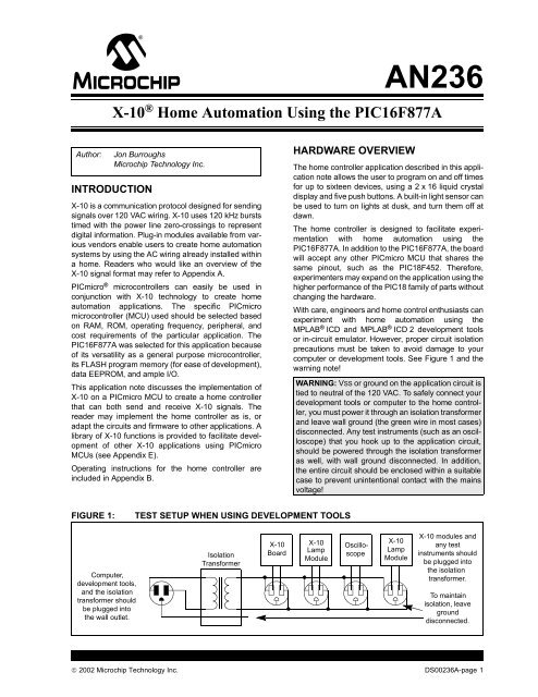
With care, engineers and home control enthusiasts can<br />
experiment with home automation using <strong>the</strong><br />
MPLAB ® ICD and MPLAB ® ICD 2 development tools<br />
or in-circuit emulator. However, proper circuit isolation<br />
precautions must be taken to avoid damage to your<br />
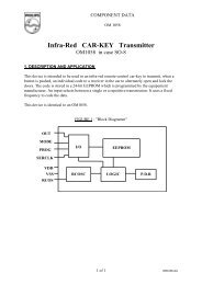
computer or development tools. See Figure 1 and <strong>the</strong><br />
warning note!<br />
WARNING: VSS or ground on <strong>the</strong> application circuit is<br />
tied to neutral of <strong>the</strong> 120 VAC. To safely connect your<br />
development tools or computer to <strong>the</strong> home controller,<br />
you must power it through an isolation transformer<br />
and leave wall ground (<strong>the</strong> green wire in most cases)<br />
disconnected. Any test instruments (such as an oscilloscope)<br />
that you hook up to <strong>the</strong> application circuit,<br />
should be powered through <strong>the</strong> isolation transformer<br />
as well, with wall ground disconnected. In addition,<br />
<strong>the</strong> entire circuit should be enclosed within a suitable<br />
case to prevent unintentional contact with <strong>the</strong> mains<br />
voltage!<br />
FIGURE 1:<br />
TEST SETUP WHEN USING DEVELOPMENT TOOLS<br />
Computer,<br />
development tools,<br />
and <strong>the</strong> isolation<br />
transformer should<br />
be plugged into<br />
<strong>the</strong> wall outlet.<br />
Isolation<br />
Transformer<br />
X-<strong>10</strong><br />
Board<br />
X-<strong>10</strong><br />
Lamp<br />
Module<br />
Oscilloscope<br />
X-<strong>10</strong><br />
Lamp<br />
Module<br />
X-<strong>10</strong> modules and<br />
any test<br />
instruments should<br />
be plugged into<br />
<strong>the</strong> isolation<br />
transformer.<br />
To maintain<br />
isolation, leave<br />
ground<br />
disconnected.<br />
© 2002 <strong>Microchip</strong> Technology Inc. DS00236A-page 1
<strong>AN236</strong><br />
HARDWARE DESCRIPTION<br />
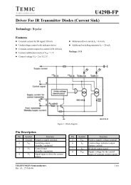
An overview of <strong>the</strong> home controller application<br />
hardware is shown in Figure 2.<br />
The hardware functionality of X-<strong>10</strong> circuitry can be<br />
divided into four functional blocks:<br />
• Zero-crossing detector<br />
• 120 kHz carrier detector<br />
• 120 kHz signal generator<br />
• Transformerless power supply<br />
There are several application functions that are not<br />
directly associated with <strong>the</strong> X-<strong>10</strong> interface. User<br />
interface functions are accomplished with an LCD<br />
display and five push buttons. A real-time clock is<br />
created using Timer1 and an external 32 kHz oscillator.<br />
User modified control data, such as unit on and off<br />
times, are stored in <strong>the</strong> PICmicro MCU’s built-in<br />
EEPROM. A light sensor and load switch are also used<br />
in this application.<br />
FIGURE 2:<br />
APPLICATION BLOCK DIAGRAM<br />
X-<strong>10</strong> FUNCTIONS<br />
Zero-crossing Detector<br />
APPLICATION SPECIFIC FUNCTIONS<br />
Light<br />
Sensor<br />
Load<br />
Switch<br />
120 kHz Carrier Detector<br />
Real-time Clock<br />
Control Data<br />
Storage<br />
120 kHz Carrier Generator<br />
USER INTERFACE<br />
LCD<br />
Key Switches<br />
TRANSFORMERLESS POWER<br />
SUPPLY<br />
DS00236A-page 2<br />
© 2002 <strong>Microchip</strong> Technology Inc.
<strong>AN236</strong><br />
A summary of resource use can be seen in Table 1.<br />
Details of <strong>the</strong> functional sections are discussed below.<br />
TABLE 1:<br />
SUMMARY OF MICROCONTROLLER RESOURCE USE<br />
Resource Function Description<br />
External interrupt on RB0 Zero-crossing Detect Generates one interrupt every zero-crossing.<br />
CCP1/Timer2 in PWM<br />
mode<br />
Timer2 interrupt through<br />
postscaler<br />
120 kHz Modulation TRISC is used to enable/disable 120 kHz output.<br />
Main oscillator is 7.680 MHz.<br />
Triac Dimmer Timing<br />
Generates dimmer timing increments for controlling<br />
Triac.<br />
Timer1 interrupt Real-time Clock Used as time keeping clock and key scan clock.<br />
One interrupt/25 ms, 40 interrupts/1 sec.<br />
Timer0 interrupt 120 kHz Envelope Timing Times duration of 1 ms bursts and onset of second<br />
and third phase bursts.<br />
ADC Light Sensor Used to detect dawn and dusk.<br />
PORTB Key Press Inputs Five push buttons are used for menu navigation.<br />
PORTB Reserved for ICD Isolation precautions required. See warning note!<br />
PORTD LCD Data pins 8 data lines for LCD.<br />
PORTE LCD Control pins 3 control lines for LCD.<br />
DATA EEPROM Non-volatile Control Data Storage Stores on and off times and o<strong>the</strong>r user<br />
programmable information.<br />
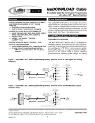
Zero-Crossing Detector<br />
In X-<strong>10</strong>, information is timed with <strong>the</strong> zero-crossings of<br />
<strong>the</strong> AC power. A zero-crossing detector is easily created<br />
by using <strong>the</strong> external interrupt on <strong>the</strong> RB0 pin and<br />
just one external component, a resistor, to limit <strong>the</strong><br />
current into <strong>the</strong> PICmicro MCU (see Figure 3).<br />
In <strong>the</strong> United States, Vrms = 117 VAC, and <strong>the</strong> peak<br />
line voltage is 165V. If we select a resistor of 5 MΩ,<br />
Ipeak = 165V/5 MΩ =33µA, which is well within <strong>the</strong><br />
current capacity of a PICmicro MCU I/O pin.<br />
Input protection diodes (designed into <strong>the</strong> PICmicro<br />
MCU I/O pins) clamp any voltage higher than VDD or<br />
lower than VSS. Therefore, when <strong>the</strong> AC voltage is in<br />
<strong>the</strong> negative half of its cycle, <strong>the</strong> RB0 pin will be<br />
clamped to VSS - 0.6V. This will be interpreted as a<br />
logic zero. When <strong>the</strong> AC voltage rises above <strong>the</strong> input<br />
threshold, <strong>the</strong> logical value will become a ‘1’.<br />
In this application, RB0 is configured for external interrupts,<br />
and <strong>the</strong> input buffer is a Schmitt trigger. This<br />
makes <strong>the</strong> input threshold 0.8 VDD = 4V on a rising<br />
edge and 0.2 VDD = 1V on a falling edge.<br />
Upon each interrupt, <strong>the</strong> Interrupt Edge Select bit within<br />
<strong>the</strong> OPTION_REG register is toggled, so that an interrupt<br />
occurs on every zero-crossing. <strong>Using</strong> <strong>the</strong> following<br />
equation, it is possible to calculate when <strong>the</strong> pin state<br />
will change relative to <strong>the</strong> zero-crossing:<br />
V = Vpk*sin(2*π*f*t), where Vpk = 165V and f = 60 Hz<br />
On a rising edge, RB0 will go high about 64 µs after <strong>the</strong><br />
zero-crossing, and on a falling edge, it will go low about<br />
16 µs before <strong>the</strong> zero-crossing.<br />
More information on interfacing PICmicro MCUs to AC<br />
power lines can be found in <strong>the</strong> application note<br />
AN521, “Interfacing to AC Power Lines”, which is<br />
available for download from <strong>the</strong> <strong>Microchip</strong> web site.<br />
FIGURE 3:<br />
120 VAC<br />
ZERO-CROSSING DETECTOR<br />
R = 5 MΩ<br />
PIC16F87XA<br />
RB0/INT<br />
© 2002 <strong>Microchip</strong> Technology Inc. DS00236A-page 3
<strong>AN236</strong><br />
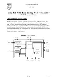
120 kHz Carrier Detector<br />
To receive X-<strong>10</strong> signals, it is necessary to detect <strong>the</strong><br />
presence of <strong>the</strong> 120 kHz signal on <strong>the</strong> AC power line.<br />
This is accomplished with a decoupling capacitor, a<br />
high-pass filter, a tuned amplifier, and an envelope<br />
detector. The components of <strong>the</strong> carrier detector are<br />
illustrated in Figure 4.<br />
Because <strong>the</strong> impedance of a capacitor is:<br />
Zc = 1/(2*π*f*C), a 0.1 µF capacitor presents a low<br />
impedance (13Ω) to <strong>the</strong> 120 kHz carrier frequency, but<br />
a high impedance (26.5 kΩ) to <strong>the</strong> 60 Hz power line frequency.<br />
This high-pass filter allows <strong>the</strong> 120 kHz signal<br />
to be safely coupled to <strong>the</strong> 60 Hz power line, and it doubles<br />
as <strong>the</strong> coupling stage of <strong>the</strong> 120 kHz carrier<br />
generator described in <strong>the</strong> next section.<br />
Since <strong>the</strong> 120 kHz carrier frequency is much higher<br />
than <strong>the</strong> 60 Hz power line frequency, it is<br />
straightforward to design an RC filter that will pass <strong>the</strong><br />
120 kHz signal and completely attenuate <strong>the</strong> 60 Hz. A<br />
high-pass filter forms <strong>the</strong> first stage of <strong>the</strong> High-Pass<br />
Filter and Tuned Amplifier Block, shown on sheet 5 of<br />
<strong>the</strong> schematics in Appendix C.<br />
For a simple high-pass filter, <strong>the</strong> -3 db breakpoint is:<br />
ƒ3 db = 1/(2*π*R*C). For C = 150 pF and R = 33 kΩ,<br />
ƒ3 db = 1/(2*π*150 pF *33 kΩ) =32kHz.<br />
This ƒ3 db point assures that <strong>the</strong> 60 Hz signal is completely<br />
attenuated, while <strong>the</strong> 120 kHz signal is passed<br />
through to <strong>the</strong> amplifier stages. Next, <strong>the</strong> 120 kHz signal<br />
is amplified using a series of inverters configured as<br />
high gain amplifiers. The first two stages are tuned<br />
amplifiers with peak response at 120 kHz. The next two<br />
stages provide additional amplification. The amplified<br />
120 kHz signal is passed through an envelope detector,<br />
formed with a diode, capacitor, and resistor. The<br />
envelope detector output is buffered through an<br />
inverter and presented to an input pin (RC3) of <strong>the</strong><br />
<strong>PIC16F877A</strong>.<br />
Upon each zero-crossing interrupt, RC3 is simply<br />
checked within <strong>the</strong> 1 ms transmission envelope to see<br />
whe<strong>the</strong>r or not <strong>the</strong> carrier is present. The presence or<br />
absence of <strong>the</strong> carrier represents <strong>the</strong> stream of ‘1’s and<br />
‘0’s that form <strong>the</strong> X-<strong>10</strong> messages described in<br />
Appendix A.<br />
FIGURE 4:<br />
120 kHz CARRIER DETECTOR<br />
Decoupling<br />
Capacitor<br />
0.1 µF<br />
X2 Rated<br />
1 MΩ<br />
High-Pass<br />
Filter & Tuned<br />
Amplifier (1)<br />
+5 VDC<br />
<strong>10</strong>K <strong>10</strong> nF<br />
Envelope Detector<br />
PIC16F87XA<br />
RC3<br />
Note 1: See schematic in Appendix C.<br />
DS00236A-page 4<br />
© 2002 <strong>Microchip</strong> Technology Inc.
<strong>AN236</strong><br />
120 kHz Carrier Generator<br />
X-<strong>10</strong> uses 120 kHz modulation to transmit information<br />
over 60 Hz power lines. It is possible to generate <strong>the</strong><br />
120 kHz carrier with an external oscillator circuit. A single<br />
I/O pin would be used to enable or disable <strong>the</strong> oscillator<br />
circuit output. However, an external oscillator<br />
circuit can be avoided by using one of <strong>the</strong> PICmicro<br />
MCU’s CCP modules.<br />
The CCP1 module is used in PWM mode to produce a<br />
120 kHz square-wave with a duty cycle of 50%.<br />
Because X-<strong>10</strong> specifies <strong>the</strong> carrier frequency at<br />
120 kHz (+/- 2 kHz), <strong>the</strong> system oscillator is chosen to<br />
be 7.680 MHz, in order for <strong>the</strong> CCP to generate precisely<br />
120 kHz. Calculations for setting <strong>the</strong> PWM<br />
period and duty cycle are shown in <strong>the</strong> code listing<br />
comments for <strong>the</strong> function InitPWM.<br />
After initialization, CCP1 is continuously enabled, and<br />
<strong>the</strong> TRISC bit for <strong>the</strong> pin is used to gate <strong>the</strong> PWM output.<br />
When <strong>the</strong> TRISC bit is set, <strong>the</strong> pin is an input and<br />
<strong>the</strong> 120 kHz signal is not presented to <strong>the</strong> pin. When<br />
<strong>the</strong> TRISC bit is clear, <strong>the</strong> pin becomes an output and<br />
<strong>the</strong> 120 kHz signal is coupled to <strong>the</strong> AC power line<br />
through a transistor amplifier and capacitor, as<br />
depicted in Figure 5.<br />
Since <strong>the</strong> impedance of a capacitor is Zc = 1/(2*π*f*C),<br />
a 0.1 µF capacitor presents a low impedance to <strong>the</strong><br />
120 kHz carrier frequency, but a high impedance to <strong>the</strong><br />
60 Hz power line frequency. This high-pass filter allows<br />
<strong>the</strong> 120 kHz signal to be safely coupled to <strong>the</strong> 60 Hz<br />
power line, and it doubles as <strong>the</strong> first stage of <strong>the</strong><br />
120 kHz carrier detector, described in <strong>the</strong> previous<br />
section.<br />
To be compatible with o<strong>the</strong>r X-<strong>10</strong> receivers, <strong>the</strong> maximum<br />
delay from <strong>the</strong> zero-crossing to <strong>the</strong> beginning of<br />
<strong>the</strong> X-<strong>10</strong> envelope should be about 300 µs. Since <strong>the</strong><br />
zero-crossing detector has a maximum delay of<br />
approximately 64 µs, <strong>the</strong> firmware must take less than<br />
236 µs after detection of <strong>the</strong> zero-crossing to begin<br />
transmission of <strong>the</strong> 120 kHz envelope.<br />
Transformerless Power Supply<br />
The <strong>PIC16F877A</strong> and o<strong>the</strong>r board circuits require a 5V<br />
supply. In this application, <strong>the</strong> X-<strong>10</strong> controller must also<br />
transmit and receive its data over <strong>the</strong> AC line. Since<br />
X-<strong>10</strong> components are intended to be plugged into a<br />
wall outlet and have a small form factor, a transformerless<br />
power supply is used. Two characteristics of transformerless<br />
supplies that should be kept in mind are<br />
limited current capacity, and lack of isolation from <strong>the</strong><br />
AC mains (see <strong>the</strong> warning note)!<br />
WARNING: This circuit is not isolated from 120 VAC.<br />
Act with caution when constructing or using such a<br />
circuit, and ensure that it is contained within a suitable<br />
insulated enclosure. Follow isolation precautions to<br />
avoid personal injury or damage to test equipment<br />
and development tools.<br />
Figure 6 illustrates <strong>the</strong> transformerless power supply<br />
used in this application. To protect <strong>the</strong> circuit from<br />
spikes on <strong>the</strong> AC power line, a 130V VDR (voltage<br />
dependent resistor) is connected between Line and<br />
Neutral. A Positive Temperature Coefficient (PTC)<br />
device acts as a resettable fuse, which limits current<br />
between Ground and Neutral. The 47Ω resistor limits<br />
current into <strong>the</strong> circuit, and <strong>the</strong> 1 MΩ resistor provides<br />
a discharge path for <strong>the</strong> voltage left on <strong>the</strong> capacitor<br />
when <strong>the</strong> circuit is unplugged from <strong>the</strong> wall. Two diodes<br />
rectify <strong>the</strong> voltage across <strong>the</strong> <strong>10</strong>00 µF capacitor and<br />
5.1V Zener diode to produce a 5V supply.<br />
The reader may wish to refer to <strong>the</strong> technical brief<br />
TB008, “Transformerless Power Supply”, available for<br />
download from <strong>the</strong> <strong>Microchip</strong> web site, for additional<br />
information on transformerless power supply design.<br />
FIGURE 5:<br />
120 kHz CARRIER GENERATOR<br />
+5 VDC<br />
High-Pass Filter<br />
PIC16F87XA<br />
OSC2<br />
RC3/CCP<br />
OSC1<br />
50Ω<br />
0.1 µF<br />
X2 Rated<br />
120 VAC<br />
7.680 MHz<br />
200Ω<br />
1 MΩ<br />
© 2002 <strong>Microchip</strong> Technology Inc. DS00236A-page 5
<strong>AN236</strong><br />
FIGURE 6:<br />
TRANSFORMERLESS POWER SUPPLY<br />
VDR<br />
N<br />
L<br />
2.25 µF<br />
1N4005<br />
+5 VDC<br />
PTC<br />
G<br />
2.25 µF<br />
1.1M<br />
1N4005<br />
<strong>10</strong>00 µF<br />
5.1V Zener<br />
Load Switch<br />
A load switch is included on <strong>the</strong> home controller so that<br />
it may act as a lamp module, with its own house and<br />
unit address. A Triac was selected as <strong>the</strong> load switch,<br />
because its medium power switching capacity and<br />
rapid switching capability make it well-suited for lamp<br />
control and dimming.<br />
A Triac is an inexpensive, three-terminal device that<br />
basically acts as a high speed, bi-directional AC switch.<br />
Two terminals, MT1 and MT2, are wired in series with<br />
<strong>the</strong> load. A small trigger current between <strong>the</strong> gate and<br />
MT1 allow conduction to occur between MT1 and MT2.<br />
Current continues to flow after <strong>the</strong> gate current is<br />
removed, as long as <strong>the</strong> load current exceeds <strong>the</strong> latching<br />
value. Because of this, <strong>the</strong> Triac will automatically<br />
switch off near each zero-crossing as <strong>the</strong> AC voltage<br />
falls below <strong>the</strong> latching voltage.<br />
A Teccor ® L4008L6 Triac was selected because it has<br />
a sensitive gate that can be directly controlled from <strong>the</strong><br />
logic level output of <strong>the</strong> PICmicro MCU I/O pin. The<br />
sensitive gate Triac can control AC current in both<br />
directions through <strong>the</strong> device, even though <strong>the</strong><br />
PICmicro MCU can provide only positive voltages to<br />
<strong>the</strong> gate.<br />
A variable dimmer is created by including a delay<br />
between <strong>the</strong> time of each zero-crossing and <strong>the</strong> time<br />
that <strong>the</strong> trigger current is provided to <strong>the</strong> Triac from <strong>the</strong><br />
PICmicro MCU.<br />
The design and control of a lamp dimmer using a<br />
PICmicro MCU is discussed in detail in PICREF-4<br />
Reference Design, “PICDIM Lamp Dimmer for <strong>the</strong><br />
PIC12C508”.<br />
FIGURE 7:<br />
LOAD SWITCH/DIMMER (TRIAC)<br />
PIC16F87XA<br />
L4008L6<br />
Return Hot<br />
MT1<br />
120 VAC In<br />
VSS<br />
RA5<br />
470Ω<br />
1N4148<br />
Gate<br />
MT2<br />
120 VAC Out<br />
DS00236A-page 6<br />
© 2002 <strong>Microchip</strong> Technology Inc.
<strong>AN236</strong><br />
LCD Module<br />
The 2-line x 16-character display uses <strong>the</strong> HD44780U<br />
Display Controller. Eight data lines and three control<br />
lines are used to interface to <strong>the</strong> PICmicro MCU. If<br />
fewer I/O pins are available, <strong>the</strong> LCD can be operated<br />
in Nibble mode using only four data lines, with some<br />
additional software overhead. A basic LCD library is<br />
included in this application, which provides <strong>the</strong><br />
necessary functions for controlling this type of LCD.<br />
Real-Time Clock<br />
A real-time clock is implemented using Timer1. The<br />
real-time clock keeps track of <strong>the</strong> present time using a<br />
routine called UpdateClock. It also determines <strong>the</strong><br />
rate that <strong>the</strong> buttons are read by a routine called<br />
ScanKeys.<br />
Timer1 is set to cause an interrupt each time it<br />
overflows. By adding a specific offset to Timer1 each<br />
time it overflows, <strong>the</strong> time before <strong>the</strong> next overflow can<br />
be precisely controlled. The button reading routine,<br />
ScanKeys, is called each time a Timer1 interrupt<br />
occurs. Since ScanKeys performs debouncing of <strong>the</strong><br />
button presses, a suitable rate to check <strong>the</strong> buttons is<br />
once every 25 ms.<br />
With a 32 kHz crystal, <strong>the</strong> counter increments once<br />
every 31.25 µs when <strong>the</strong> prescaler is set to 1:1. In order<br />
for Timer1 to generate an interrupt once every 25 ms,<br />
TMR1H:TMR1L are pre-loaded with 0xFCE0h.<br />
The Timer1 interrupt interval, or tick, can be seen in <strong>the</strong><br />
following equation:<br />
(FFFFh – FCE0h)*1/32 kHz = .025 s = 1 tick<br />
Each time ScanKeys is called (every 25 ms), it calls<br />
UpdateClock. UpdateClock keeps track of <strong>the</strong> time<br />
unit variables: ticks, seconds, minutes, and hours.<br />
Since every 25 ms equals one tick, seconds are incremented<br />
every 40 ticks. Minutes and hours are<br />
incremented in a similar fashion.<br />
development tool, without taking first isolating <strong>the</strong><br />
entire application from wall power (see <strong>the</strong> previous<br />
warning notes)!<br />
Control Data Storage<br />
Certain control data that is programmable by <strong>the</strong> user<br />
must be stored in non-volatile memory. The PICmicro<br />
MCU’s built-in EEPROM is well-suited to this task.<br />
To use EEPROM memory space most efficiently (by<br />
avoiding wasted bits), on/off times and light sensor<br />
control flags are stored using <strong>the</strong> format shown in<br />
Figure 8. Figure 9 shows <strong>the</strong> location of on/off times<br />
and o<strong>the</strong>r information within <strong>the</strong> data EEPROM. <strong>Using</strong><br />
this data organization, only 48 bytes of EEPROM are<br />
required to store <strong>the</strong> on/off times and light sensor<br />
control flags for 16 units.<br />
FIGURE 8:<br />
4 bits 4 bits<br />
EEHours On Hour Off Hour<br />
1 1 6 bits<br />
EEOnMinutes A B OnMin<br />
1 1 6 bits<br />
EEOffMinutes C D Off Min<br />
FIGURE 9:<br />
0x001<br />
0x002<br />
0x0<strong>10</strong><br />
0x011<br />
0x012<br />
ON/OFF TIME STORAGE<br />
EEPROM DATA<br />
Address Unit Data<br />
0x020<br />
0x021<br />
0x022<br />
System<br />
System<br />
Unit 1<br />
Unit 2<br />
Unit 3<br />
Unit 1<br />
Unit 2<br />
Unit 3<br />
A = AM/PM bit for On Hour<br />
B = Control bit for On at Dusk<br />
C = AM/PM bit for Off Hour<br />
D = Control bit for Off at Dawn<br />
House Address<br />
Unit Address<br />
OnHour<br />
OnHour<br />
OnHour<br />
A B<br />
A B<br />
A B<br />
OffHour<br />
OffHour<br />
OffHour<br />
OnMin<br />
OnMin<br />
OnMin<br />
Push Buttons<br />
Five push buttons, connected to RB1-RB5, are used for<br />
user interaction with <strong>the</strong> application. Each normally open<br />
push button will pull a port pin low when it is pressed.<br />
0x030<br />
0x031<br />
0x032<br />
Unit 1<br />
Unit 2<br />
Unit 3<br />
A B<br />
A B<br />
A B<br />
OffMin<br />
OffMin<br />
OffMin<br />
Light Sensor<br />
To detect <strong>the</strong> ambient light level, a CdS photoresistor is<br />
used in conjunction with an 820Ω resistor to create a<br />
voltage divider. The voltage on <strong>the</strong> divider varies with<br />
<strong>the</strong> intensity of ambient light and is connected to an<br />
analog channel (AN0) of <strong>the</strong> microcontroller.<br />
In-Circuit Debugger<br />
RB6 and RB7 have been reserved for In-Circuit Serial<br />
Programming TM (ICSP TM ) and <strong>the</strong> in-circuit debugger<br />
(ICD). However, do not connect <strong>the</strong> ICD or any o<strong>the</strong>r<br />
Each time that minutes are incremented within <strong>the</strong><br />
UpdateClock routine, a flag is set that enables a routine<br />
called CheckOnOffTimes to be called from <strong>the</strong><br />
main loop. CheckOnOffTimes compares <strong>the</strong> present<br />
time with <strong>the</strong> unit on and off times stored in EEPROM<br />
memory. If <strong>the</strong>re is a match, <strong>the</strong>n a flag is set to ei<strong>the</strong>r<br />
turn <strong>the</strong> unit on or off, by sending it <strong>the</strong> appropriate X-<strong>10</strong><br />
command when <strong>the</strong> routine ControlX<strong>10</strong>Units is<br />
called.<br />
© 2002 <strong>Microchip</strong> Technology Inc. DS00236A-page 7
<strong>AN236</strong><br />
APPLICATION FIRMWARE<br />
OVERVIEW<br />
The firmware is divided into several different files to<br />
facilitate adaptation of <strong>the</strong> code to o<strong>the</strong>r applications.<br />
Following is a summary of <strong>the</strong> files associated with this<br />
application note:<br />
• x<strong>10</strong>lib.asm Defines X-<strong>10</strong> functions.<br />
• x<strong>10</strong>lib.inc Defines X-<strong>10</strong> constants and<br />
macros.<br />
• x<strong>10</strong>hc.asm Main application code for <strong>the</strong><br />
home controller.<br />
• x<strong>10</strong>demo.asm Example code that shows how<br />
to use <strong>the</strong> X-<strong>10</strong> library macros.<br />
• lcd.asm Defines <strong>the</strong> routines necessary<br />
for driving <strong>the</strong> LCD.<br />
• p16f877A.lkr Standard linker file for<br />
<strong>PIC16F877A</strong> parts.<br />
• p16f877A.inc Standard include file for<br />
<strong>PIC16F877A</strong> parts.<br />
Detailed descriptions of operation can be found in <strong>the</strong><br />
comments within <strong>the</strong> code listing. The X-<strong>10</strong> library<br />
functions and macros are described in <strong>the</strong> next section.<br />
X-<strong>10</strong> LIBRARY<br />
A simple library of commands was developed and used<br />
for <strong>the</strong> home controller. It can be used with little or no<br />
modification in a user’s application. The library consists<br />
of two files: x<strong>10</strong>lib.asm and x<strong>10</strong>lib.inc.<br />
To use <strong>the</strong> library, a user need only understand <strong>the</strong><br />
function of <strong>the</strong> macros defined in x<strong>10</strong>lib.inc. The<br />
macros greatly simplify <strong>the</strong> use of <strong>the</strong> library by eliminating<br />
<strong>the</strong> need for <strong>the</strong> user to understand every X-<strong>10</strong><br />
function in x<strong>10</strong>lib.asm. Examples of how <strong>the</strong> macros<br />
are used are included in <strong>the</strong> file x<strong>10</strong>demo.asm.<br />
The macros are explained below:<br />
InitX<strong>10</strong><br />
This macro is used to initialize <strong>the</strong> peripherals that provide<br />
X-<strong>10</strong> functionality. It must be called in <strong>the</strong> application<br />
program before any of <strong>the</strong> below macros will work.<br />
It is used as follows:<br />
InitX<strong>10</strong><br />
SkipIfTxReady<br />
Before sending an X-<strong>10</strong> message, it is necessary to<br />
make sure that ano<strong>the</strong>r message is not already being<br />
sent, which is signified by <strong>the</strong> X<strong>10</strong>TxFlag being set.<br />
This macro simply checks that flag and skips <strong>the</strong> next<br />
instruction if it is okay to begin a new transmission.<br />
O<strong>the</strong>rwise, <strong>the</strong>re is a chance that a new transmission<br />
will interrupt an ongoing transmission.<br />
It is used as follows:<br />
SkipIfTxDone<br />
GOTO $-1 ;loop until ready to<br />
;transmit next message<br />
SendX<strong>10</strong>Address (House, Unit)<br />
This macro is used to send an X-<strong>10</strong> address for a particular<br />
unit. It requires two arguments, a house address<br />
and unit address. The definitions for all house and unit<br />
addresses are defined in x<strong>10</strong>lib.inc. To use this<br />
macro to send <strong>the</strong> address for unit 16 at house P, one<br />
simply types:<br />
SendX<strong>10</strong>Address HouseP, Unit16<br />
SendX<strong>10</strong>AddressVar<br />
This macro is used to send an X-<strong>10</strong> address, defined<br />
by variables ra<strong>the</strong>r than constants. To send an address<br />
contained in <strong>the</strong> user variables MyHouse and MyUnit,<br />
<strong>the</strong> following sequence would be applied:<br />
MOVF MyHouse, W ;contains a value<br />
;from 0-16<br />
MOVWF TxHouse<br />
MOVF MyUnit, W ;contains a value<br />
;from 0-16<br />
MOVWF TxUnit<br />
SendX<strong>10</strong>AddressVar<br />
DS00236A-page 8<br />
© 2002 <strong>Microchip</strong> Technology Inc.
<strong>AN236</strong><br />
SendX<strong>10</strong>Command (House, Function)<br />
This macro is used to send an X-<strong>10</strong> command. It<br />
requires two arguments, <strong>the</strong> house address and function<br />
code. The definitions for all house addresses and<br />
function codes are defined in x<strong>10</strong>lib.inc. To use this<br />
macro to send <strong>the</strong> command ‘All Lights On’ to all units<br />
at house A, one types:<br />
SendX<strong>10</strong>Command HouseA, AllLightsOn<br />
SendX<strong>10</strong>CommandVar<br />
This macro is used to send an X-<strong>10</strong> command, defined<br />
by a variable ra<strong>the</strong>r than a constant. To use this macro<br />
to send <strong>the</strong> command stored in <strong>the</strong> user variable<br />
MyCommand to all units at MyHouse, one types:<br />
MOVF MyHouse, W ;contains a value<br />
;from 0-16<br />
MOVWF TxHouse<br />
MOVF MyCommand, W ;any X-<strong>10</strong><br />
;function<br />
;defined in<br />
;x<strong>10</strong>lib.inc<br />
MOVWF TxFunction<br />
SendX<strong>10</strong>CommandVar<br />
SkipIfRxDone<br />
Before reading an X-<strong>10</strong> message, it is necessary to<br />
make sure that a complete message has been<br />
received. This is signified by <strong>the</strong> X<strong>10</strong>RxFlag being set.<br />
This macro simply checks that flag and skips <strong>the</strong> next<br />
instruction if a new X-<strong>10</strong> message has been received.<br />
It is used as follows:<br />
SkipIfRxDone<br />
GOTO $-1 ;loop until message<br />
;received<br />
SkipIfAddressRcvd<br />
It may be necessary to make sure that an address was<br />
received by using this macro, which checks to see if <strong>the</strong><br />
RxCommandFlag is clear.<br />
It is used as follows:<br />
SkipIfAddressRcvd<br />
GOTO $-1 ;loop until address<br />
;received<br />
SkipIfCommandRcvd<br />
Or, it may be necessary to make sure that a command<br />
was received by using this macro, which checks to see<br />
if <strong>the</strong> RxCommandFlag is set.<br />
It is used as follows:<br />
SkipIfCommandRcvd<br />
GOTO $-1 ;loop until command<br />
;received<br />
ReadX<strong>10</strong>Message<br />
This macro is called to read a received X-<strong>10</strong> message,<br />
which may be ei<strong>the</strong>r an address or a command. If <strong>the</strong><br />
message was an address, <strong>the</strong>n <strong>the</strong> received house and<br />
unit codes will be stored in <strong>the</strong> variables RxHouse and<br />
RxUnit, respectively. If <strong>the</strong> message was a command,<br />
<strong>the</strong>n <strong>the</strong> received house address and function code will<br />
be stored in <strong>the</strong> variables RxHouse and RxFunction.<br />
It is simply called as follows:<br />
ReadX<strong>10</strong>Message<br />
Please refer to <strong>the</strong> example code in x<strong>10</strong>demo.asm to<br />
see how each of <strong>the</strong>se macros is used in a simple<br />
application.<br />
© 2002 <strong>Microchip</strong> Technology Inc. DS00236A-page 9
<strong>AN236</strong><br />
Memory Usage<br />
Memory usage for <strong>the</strong> X-<strong>10</strong> portion of <strong>the</strong> application is<br />
summarized in Table 2.<br />
TABLE 2:<br />
SUMMARY OF MEMORY USAGE FOR X-<strong>10</strong> FUNCTIONALITY<br />
Memory Type Used Available on <strong>PIC16F877A</strong> Percent Used<br />
FLASH Program Memory 437 words 8453 words 5%<br />
Data Memory (RAM) 62 bytes 368 bytes 17%<br />
EEPROM Data Memory 0 bytes 256 bytes 0%<br />
Memory usage for <strong>the</strong> entire home controller<br />
application is summarized in Table 3.<br />
TABLE 3: SUMMARY OF MEMORY USAGE FOR THE HOME CONTROLLER<br />
Memory Type Used Available on <strong>PIC16F877A</strong> Percent Used<br />
FLASH Program Memory 3762 words 8453 words 44.5%<br />
Data Memory (RAM) 168 bytes 368 bytes 45.6%<br />
EEPROM Data Memory 51 bytes 256 bytes 20%<br />
DS00236A-page <strong>10</strong><br />
© 2002 <strong>Microchip</strong> Technology Inc.
<strong>AN236</strong><br />
CONCLUSION<br />
The PICmicro MCU is well-suited to X-<strong>10</strong> applications.<br />
With its plethora of on-chip peripherals and a few external<br />
components, a PICmicro MCU can be used to<br />
implement an X-<strong>10</strong> system that can transmit and<br />
receive messages over <strong>the</strong> AC power line wiring. The<br />
small code size of <strong>the</strong> X-<strong>10</strong> library leaves ample space<br />
for <strong>the</strong> user to create application specific code.<br />
PICmicro MCUs, such as <strong>the</strong> <strong>PIC16F877A</strong>, have plenty<br />
of additional resources for creating more complex X-<strong>10</strong><br />
applications, while smaller PICmicro MCUs can be<br />
selected for economical use in simpler X-<strong>10</strong><br />
applications.<br />
USEFUL WEB REFERENCES<br />
• http://www.abacuselectrics.com/x<strong>10</strong>.htm<br />
This web site describes how to build an appliance<br />
module that utilizes <strong>the</strong> PIC16C52 or PIC16F84.<br />
Parts of this project’s receiver circuit, designed by<br />
Phil Plunkett, were adapted to <strong>the</strong> home controller<br />
application.<br />
• http://www.microchip.com<br />
The <strong>Microchip</strong> web site features data sheets, product<br />
information, and more. Helpful technical<br />
documentation available here include:<br />
AN521 “Interfacing to AC Power Lines”<br />
TB008 “Transformerless Power Supply”<br />
PICREF-4 “PICDIM Lamp Dimmer for <strong>the</strong><br />
PIC12C508”<br />
• http://www.x<strong>10</strong>.com/support<br />
The X<strong>10</strong> Wireless Technology, Inc. TM web site features<br />
technical information and FAQs pertaining to<br />
<strong>the</strong> X-<strong>10</strong> communication protocol.<br />
© 2002 <strong>Microchip</strong> Technology Inc. DS00236A-page 11
<strong>AN236</strong><br />
APPENDIX A: HOW DOES THE X-<strong>10</strong><br />
PROTOCOL WORK?<br />
X-<strong>10</strong> transmissions are synchronized with <strong>the</strong><br />
zero-crossings on <strong>the</strong> AC power line. By monitoring for<br />
<strong>the</strong> zero-crossings, X-<strong>10</strong> devices know when to transmit<br />
or receive X-<strong>10</strong> information. A binary ‘1’ is represented<br />
by a 1 ms long burst of 120 kHz, near <strong>the</strong><br />
zero-crossing point of <strong>the</strong> AC. A binary zero is<br />
represented by <strong>the</strong> lack of <strong>the</strong> 120 kHz burst.<br />
FIGURE A-1:<br />
X-<strong>10</strong> TRANSMISSION TIMING<br />
(1)<br />
(1)<br />
120 kHz<br />
60 Hz<br />
1 ms<br />
2.778 ms<br />
5.556 ms<br />
8.333 ms<br />
(1)<br />
(1)<br />
Note 1: These 120 kHz carrier bursts are timed to coincide with <strong>the</strong> zero-crossing of <strong>the</strong> o<strong>the</strong>r phases,<br />
when implemented.<br />
A complete X-<strong>10</strong> message is composed of a start code<br />
(11<strong>10</strong>), followed by a house code, followed by a key<br />
code. The key code may be ei<strong>the</strong>r a unit address or a<br />
function code, depending on whe<strong>the</strong>r <strong>the</strong> message is<br />
an address or a command. Table A-1 and Table A-2<br />
show <strong>the</strong> possible values of <strong>the</strong> house and key codes.<br />
DS00236A-page 12<br />
© 2002 <strong>Microchip</strong> Technology Inc.
<strong>AN236</strong><br />
TABLE A-1:<br />
House<br />
Addresses<br />
TABLE A-2:<br />
Function Codes<br />
HOUSE CODES<br />
House Codes<br />
H1 H2 H4 H8<br />
A 0 1 1 0<br />
B 1 1 1 0<br />
C 0 0 1 0<br />
D 1 0 1 0<br />
E 0 0 0 1<br />
F 1 0 0 1<br />
G 0 1 0 1<br />
H 1 1 0 1<br />
I 0 1 1 1<br />
J 1 1 1 1<br />
K 0 0 1 1<br />
L 1 0 1 1<br />
M 0 0 0 0<br />
N 1 0 0 0<br />
O 0 1 0 0<br />
P 1 1 0 0<br />
KEY CODES<br />
Key Codes<br />
Unit Addresses<br />
D1 D2 D4 D8 D16<br />
1 0 1 1 0 0<br />
2 1 1 1 0 0<br />
3 0 0 1 0 0<br />
4 1 0 1 0 0<br />
5 0 0 0 1 0<br />
6 1 0 0 1 0<br />
7 0 1 0 1 0<br />
8 1 1 0 1 0<br />
9 0 1 1 1 0<br />
<strong>10</strong> 1 1 1 1 0<br />
11 0 0 1 1 0<br />
12 1 0 1 1 0<br />
13 0 0 0 0 0<br />
14 1 0 0 0 0<br />
15 0 1 0 0 0<br />
16 1 1 0 0 0<br />
All Units Off 0 0 0 0 1<br />
All Units On 0 0 0 1 1<br />
On 0 0 1 0 1<br />
Off 0 0 1 1 1<br />
Dim 0 1 0 0 1<br />
Bright 0 1 0 1 1<br />
All Lights Off 0 1 1 0 1<br />
Extended Code 0 1 1 1 1<br />
Hail Request 1 0 0 0 1<br />
Hail Acknowledge 1 0 0 1 1<br />
Pre-set Dim 1 0 1 X 1<br />
Extended Code 1 1 0 0 1<br />
(Analog)<br />
Status = On 1 1 0 1 1<br />
Status = Off 1 1 1 0 1<br />
Status Request 1 1 1 1 1<br />
When transmitting <strong>the</strong> codes in Table A-1 and<br />
Table A-2, two zero-crossings are used to transmit<br />
each bit as complementary bit pairs (i.e., a zero is represented<br />
by 0-1, and a one is represented by 1-0). For<br />
example, in order to send <strong>the</strong> house code A, <strong>the</strong> four-bit<br />
code in Table A-1 is 01<strong>10</strong>, and <strong>the</strong> code transmitted as<br />
complimentary bit pairs is 01<strong>10</strong><strong>10</strong>01. Since house and<br />
key codes are sent using <strong>the</strong> complimentary format, <strong>the</strong><br />
start code is <strong>the</strong> only place where <strong>the</strong> pattern 11<strong>10</strong> will<br />
appear in an X-<strong>10</strong> data stream.<br />
The key code, which is 5-bits long in Table A-2, takes<br />
<strong>10</strong> bits to represent in <strong>the</strong> complimentary format.<br />
Because <strong>the</strong> last bit of <strong>the</strong> key code is always zero for<br />
a unit address and one for a function code, <strong>the</strong> last bit<br />
of <strong>the</strong> key code can be treated as a suffix that denotes<br />
whe<strong>the</strong>r <strong>the</strong> key code is a unit address or function<br />
code.<br />
A complete block of data consists of <strong>the</strong> start code,<br />
house code, key code and suffix. Each data block is<br />
sent twice, with 3 power line cycles, or six<br />
zero-crossings, between each pair of data blocks.<br />
For example, to turn on an X-<strong>10</strong> module assigned to<br />
house code A, unit 2, <strong>the</strong> following data stream would<br />
be sent on <strong>the</strong> power line, one bit per zero-crossing.<br />
First, send <strong>the</strong> address twice:<br />
11<strong>10</strong> 01<strong>10</strong><strong>10</strong>01 <strong>10</strong><strong>10</strong><strong>10</strong>01 01<br />
START HOUSE A UNIT 2 Suffix<br />
11<strong>10</strong> 01<strong>10</strong><strong>10</strong>01 <strong>10</strong><strong>10</strong><strong>10</strong>01 01<br />
START HOUSE A UNIT 2 Suffix<br />
Next, wait for three cycles (six zero-crossings):<br />
000000<br />
Then, send <strong>the</strong> command twice:<br />
11<strong>10</strong> 01<strong>10</strong><strong>10</strong>01 0<strong>10</strong>1<strong>10</strong>01 <strong>10</strong><br />
START HOUSE A ON Suffix<br />
11<strong>10</strong> 01<strong>10</strong><strong>10</strong>01 0<strong>10</strong>1<strong>10</strong>01 <strong>10</strong><br />
START HOUSE A ON Suffix<br />
Lastly, wait for three cycles (six zero-crossings) before<br />
sending <strong>the</strong> next block:<br />
000000<br />
There are exceptions to this format. For example, <strong>the</strong><br />
bright and dim codes do not require <strong>the</strong> 3-cycle wait<br />
between consecutive dim commands or consecutive<br />
bright commands. For a complete discussion of all<br />
X-<strong>10</strong> messages, please refer to <strong>the</strong> X<strong>10</strong> Wireless<br />
Technology, Inc. web site (see <strong>the</strong> "USEFUL WEB<br />
REFERENCES" section).<br />
© 2002 <strong>Microchip</strong> Technology Inc. DS00236A-page 13
<strong>AN236</strong><br />
APPENDIX B:<br />
Welcome Screen<br />
HOME CONTROLLER<br />
OPERATING<br />
INSTRUCTIONS<br />
The home controller user interface consists of five buttons<br />
and a 2 x 16 LCD. Upon power-up, <strong>the</strong> Welcome<br />
screen is displayed. This screen displays a welcome<br />
message and <strong>the</strong> time. Immediately, <strong>the</strong> seconds begin<br />
incrementing and <strong>the</strong> PICmicro MCU begins keeping<br />
track of <strong>the</strong> time.<br />
Figure B-1 shows <strong>the</strong> Welcome screen and <strong>the</strong> location<br />
and functionality of each button. Depending on <strong>the</strong><br />
screen viewed, each of <strong>the</strong> five buttons performs a<br />
different function.<br />
When <strong>the</strong> Welcome screen is displayed, <strong>the</strong> buttons<br />
enable access to <strong>the</strong> following functions:<br />
• Press menu to enter <strong>the</strong> Select Function screen.<br />
• Press up to brighten <strong>the</strong> lamp that is plugged into<br />
<strong>the</strong> home controller.<br />
• Press down to dim <strong>the</strong> lamp.<br />
• Press enter to turn <strong>the</strong> lamp on.<br />
• Press exit to turn <strong>the</strong> lamp off.<br />
FIGURE B-1:<br />
WELCOME SCREEN<br />
Welcome <strong>Home</strong><br />
12:00:00 AM<br />
menu<br />
Select Function Screen<br />
up down enter exit<br />
When viewing <strong>the</strong> Welcome screen, <strong>the</strong> menu button<br />
enables access to <strong>the</strong> Select Function screen. Each<br />
successive press of <strong>the</strong> menu button cycles through<br />
<strong>the</strong> four main functions of <strong>the</strong> user interface: setting <strong>the</strong><br />
system time, setting <strong>the</strong> system address, setting <strong>the</strong><br />
light sensor, or programming <strong>the</strong> unit on and off times,<br />
as illustrated in Figure B-2.<br />
FIGURE B-2:<br />
Select Function<br />
Set System Time<br />
menu up down enter exit<br />
Select Function<br />
Program Unit<br />
SELECT FUNCTION<br />
SCREENS<br />
Set System Time Screen<br />
Use <strong>the</strong> Set System Time screen to set <strong>the</strong> time.<br />
SETTING SYSTEM TIME<br />
1. Starting from <strong>the</strong> Welcome screen, press menu<br />
until <strong>the</strong> Set System Time screen is displayed<br />
and press enter.<br />
2. Press up/down to set <strong>the</strong> hours.<br />
3. Press enter when <strong>the</strong> correct hour, including AM<br />
or PM, has been selected.<br />
4. Repeat this process to set <strong>the</strong> minutes.<br />
5. If <strong>the</strong> time is correct, select Y (<strong>the</strong> default) using<br />
<strong>the</strong> up/down buttons and press enter. This<br />
returns to <strong>the</strong> Welcome screen with <strong>the</strong> new<br />
time displayed.<br />
6. If <strong>the</strong> time is not correct, select N and press<br />
enter. This will return <strong>the</strong> user to step 2 so <strong>the</strong><br />
correct time can be entered.<br />
7. Press exit at any time to return <strong>the</strong> user to <strong>the</strong><br />
Welcome screen without saving <strong>the</strong> new time.<br />
FIGURE B-3:<br />
1 2<br />
menu up down enter exit<br />
4<br />
Set System Time<br />
12:00 AM Set hrs<br />
menu<br />
Select Function<br />
Set System Addr<br />
menu up down enter exit<br />
Select Function<br />
Set Light Sensor<br />
menu up down enter exit<br />
SET SYSTEM TIME SCREENS<br />
up down enter exit<br />
1<br />
3<br />
Set System Time<br />
12:00 AM Set min<br />
menu up down enter exit<br />
Set System Time<br />
12:00 AM Okay? Y<br />
2<br />
menu up down enter<br />
3<br />
exit<br />
DS00236A-page 14<br />
© 2002 <strong>Microchip</strong> Technology Inc.
<strong>AN236</strong><br />
Select System Address Screen<br />
Use <strong>the</strong> Set System Address screen to set <strong>the</strong> house<br />
address and unit address of <strong>the</strong> home controller.<br />
SETTING HOUSE/UNIT ADDRESS<br />
1. From <strong>the</strong> Welcome screen, press menu until <strong>the</strong><br />
Set System Addr screen is displayed and press<br />
enter.<br />
2. Press up or down to set <strong>the</strong> house address (a<br />
letter from A - P).<br />
3. Press enter when <strong>the</strong> house address has been<br />
selected.<br />
4. Repeat steps 2 and 3 to set <strong>the</strong> unit address (a<br />
number from 1 - 16).<br />
5. If <strong>the</strong> house and unit addresses are correct,<br />
select Y (<strong>the</strong> default) using <strong>the</strong> up/down buttons<br />
and press enter. This returns to <strong>the</strong> Welcome<br />
screen with <strong>the</strong> new address stored in<br />
non-volatile memory.<br />
6. If <strong>the</strong> address is not correct, select N and press<br />
enter. This will return <strong>the</strong> user to step 2.<br />
7. Press exit at any time to return <strong>the</strong> user to <strong>the</strong><br />
Welcome screen without saving <strong>the</strong> new<br />
address.<br />
FIGURE B-4:<br />
SET SYSTEM ADDRESS<br />
SCREENS<br />
Set System Addr<br />
A-01 Set House<br />
menu<br />
up down enter exit<br />
1<br />
Set System Addr<br />
A-01 Okay? Y<br />
menu up down enter<br />
3<br />
exit<br />
Set System Addr<br />
A-01 Set Unit<br />
menu up down enter exit<br />
2<br />
Set Light Sensor Screen<br />
Use <strong>the</strong> Set Light Sensor screen to select whe<strong>the</strong>r<br />
units turn on at dusk, or off at dawn.<br />
SETTING THE LIGHT SENSOR<br />
1. From <strong>the</strong> Welcome screen, press menu until <strong>the</strong><br />
Set Light Sensor screen is displayed and press<br />
enter.<br />
2. Press up or down to select <strong>the</strong> desired unit. The<br />
house address will already be set to <strong>the</strong> system<br />
house address.<br />
3. Press enter when <strong>the</strong> desired unit address has<br />
been selected.<br />
4. Press up or down to select whe<strong>the</strong>r or not <strong>the</strong><br />
unit should turn on at dusk, and press enter.<br />
5. Repeat this process to set o<strong>the</strong>r units as<br />
desired.<br />
6. Press exit to return to <strong>the</strong> Welcome screen.<br />
Pressing exit while <strong>the</strong> “On at Dusk” or “Off at<br />
Dawn” prompt is displayed will return <strong>the</strong> user to<br />
<strong>the</strong> Welcome screen without modifying that<br />
parameter.<br />
FIGURE B-5:<br />
SET LIGHT SENSOR<br />
SCREENS<br />
Set Light Sensor<br />
A-01 Set Unit<br />
menu<br />
up down enter exit<br />
1<br />
Set Light Sensor<br />
Off at Dawn? Y<br />
menu up down enter<br />
3<br />
exit<br />
Set Light Sensor<br />
On at Dusk? Y<br />
menu up down enter exit<br />
2<br />
© 2002 <strong>Microchip</strong> Technology Inc. DS00236A-page 15
<strong>AN236</strong><br />
Program Unit Screen<br />
Use <strong>the</strong> Program Unit screen to program on and off<br />
times for different units.<br />
PROGRAMMING UNIT ON AND OFF TIMES<br />
1. From <strong>the</strong> Welcome screen, press menu repeatedly<br />
until <strong>the</strong> Program Unit screen is displayed<br />
and press enter.<br />
2. Press up or down to select <strong>the</strong> desired unit. The<br />
house address will already be set to <strong>the</strong> system<br />
house address.<br />
3. Press enter when <strong>the</strong> unit address has been<br />
selected.<br />
4. Press up or down to set <strong>the</strong> ‘on’ time hours.<br />
Hours set to ‘00’ means that <strong>the</strong> unit will not be<br />
turned on at any time.<br />
5. Press enter when <strong>the</strong> correct hour, including AM<br />
or PM, has been selected.<br />
6. Repeat this process to set <strong>the</strong> ‘on’ time minutes.<br />
If <strong>the</strong> hour has been set to ‘00’, <strong>the</strong>n <strong>the</strong> minutes<br />
will be set to ‘00’ automatically.<br />
7. If <strong>the</strong> time is correct, select Y (<strong>the</strong> default) using<br />
<strong>the</strong> up/down buttons and press enter. The user<br />
will be prompted to program <strong>the</strong> ‘off’ time in a<br />
similar fashion.<br />
8. If <strong>the</strong> time is not correct, select N and press<br />
enter. This allows <strong>the</strong> user to re-enter <strong>the</strong> hour<br />
and minutes by returning to step 2.<br />
9. Repeat this process to set <strong>the</strong> ‘on’ and ‘off’ time<br />
for o<strong>the</strong>r units as desired.<br />
<strong>10</strong>. Press exit to return to <strong>the</strong> Welcome screen.<br />
Pressing exit while <strong>the</strong> “Set Hours” or “Set Min”<br />
prompt is displayed will return <strong>the</strong> user to <strong>the</strong><br />
Welcome screen without modifying any<br />
parameters.<br />
FIGURE B-6:<br />
PROGRAM UNIT ‘ON’ TIME<br />
SCREENS<br />
N<br />
Program Unit<br />
A-01 Set Unit<br />
menu up down enter exit<br />
Program On-Time<br />
00:00AM Set hrs<br />
menu up down enter exit<br />
Program On-Time<br />
00:00AM Set min<br />
menu up down enter exit<br />
Program On-Time<br />
00:00AM Okay? Y<br />
menu up down enter exit<br />
Y<br />
Program Off-Time<br />
00:00AM Set hrs<br />
menu up down enter exit<br />
Program Off-Time<br />
00:00AM Set min<br />
menu up down enter exit<br />
N<br />
Program Off-Time<br />
00:00AM Okay? Y<br />
menu up down enter exit<br />
Y<br />
DS00236A-page 16<br />
© 2002 <strong>Microchip</strong> Technology Inc.
<strong>AN236</strong><br />
APPENDIX C:<br />
X-<strong>10</strong> SCHEMATICS<br />
FIGURE C-1: SHEET 1 OF 5<br />
MCLR<br />
CDS<br />
TRIAC<br />
ZEROX<br />
UP<br />
DOWN<br />
MENU<br />
ENTER<br />
EXIT<br />
U1<br />
RE2<br />
RE1<br />
RE0<br />
RD7<br />
RD6<br />
RD5<br />
RD4<br />
RD3<br />
RD2<br />
RD1<br />
RD0<br />
XIN<br />
XOUT<br />
© 2002 <strong>Microchip</strong> Technology Inc. DS00236A-page 17
<strong>AN236</strong><br />
FIGURE C-2: SHEET 2 OF 5<br />
MENU UP<br />
RE2<br />
RE1<br />
RE0<br />
DOWN<br />
LCD1<br />
CDS<br />
ENTER<br />
RD0<br />
RD1<br />
RD2<br />
RD3<br />
RD4<br />
RD5<br />
RD6<br />
RD7<br />
EXIT<br />
DS00236A-page 18<br />
© 2002 <strong>Microchip</strong> Technology Inc.
<strong>AN236</strong><br />
FIGURE C-3: SHEET 3 OF 5<br />
TRIAC<br />
XIOCIRCUITS<br />
+5V<br />
© 2002 <strong>Microchip</strong> Technology Inc. DS00236A-page 19
<strong>AN236</strong><br />
FIGURE C-4: SHEET 4 OF 5<br />
XIOCIRCUITS<br />
XOUT<br />
CARRIERDATA<br />
ZEROX<br />
DS00236A-page 20<br />
© 2002 <strong>Microchip</strong> Technology Inc.
<strong>AN236</strong><br />
FIGURE C-5: SHEET 5 OF 5<br />
CARRIERDATA<br />
XIN<br />
© 2002 <strong>Microchip</strong> Technology Inc. DS00236A-page 21
<strong>AN236</strong><br />
APPENDIX D:<br />
PARTS LIST<br />
Count Reference Value Description<br />
2 D7, D8 6.8V Zener Diode<br />
2 D4, D5 1N4005 Diode<br />
2 D3, D9 1N4148 Diode<br />
1 D6 5.1V Zener Diode<br />
1 Q2 2N2222 NPN Transistor<br />
1 J2 Power In Connector<br />
2 J1 Power Out Connector<br />
1 U2 CD4069 HEX Inverters<br />
8 C1, C2, C3, C8, C9, C<strong>10</strong>, C11, C12 0.1 µF Capacitor<br />
4 C4, C5, C6, C7 15 pF Capacitor<br />
1 C13 0.1 µF Capacitor<br />
2 C14, C15 2.25 µF, 250V x2 Capacitor<br />
2 C21, C22 3.3 nF Capacitor<br />
2 C25, C26 4.7 nF Capacitor<br />
1 C20 <strong>10</strong> nF Capacitor<br />
2 C23, C24 <strong>10</strong> pF Capacitor<br />
1 C27 <strong>10</strong>0 pF Capacitor<br />
2 C18, C19 150 pF Capacitor<br />
1 C16 <strong>10</strong>00 µF, 25V Capacitor<br />
1 C17 0.1 µF, 275 VAC x2 Capacitor<br />
1 Y2 7.680 MHz Crystal<br />
1 Y1 32 kHz Crystal<br />
2 L1, L2 220 µH Axial Lead Inductor<br />
1 LCD1 CG161 HD44780-based 2x16 Liquid Crystal Display<br />
2 D1, D2 LTL-94PEKTA LEDs<br />
1 U1 <strong>PIC16F877A</strong> Microcontroller<br />
1 R6 20 kΩ Potentiometer<br />
1 PTC1 CdS Cell<br />
1 PTC2 Resettable PTC's Resistor<br />
1 R18 1 MΩ Resistor<br />
1 R14 1.1 MΩ Resistor<br />
1 R13 2 MΩ Resistor<br />
1 R17 5 MΩ Resistor<br />
7 R1, R4, R5, R7, R8, R9, R21 <strong>10</strong> kΩ Resistor<br />
1 R22 33 kΩ Resistor<br />
1 R25 47 kΩ Resistor<br />
1 R19 50 kΩ Resistor<br />
1 R16 <strong>10</strong>0 kΩ Resistor<br />
2 R15, R23 <strong>10</strong>0 kΩ Resistor<br />
1 R20 200Ω Resistor<br />
1 R24 220 kΩ Resistor<br />
2 R2, R3 680Ω Resistor<br />
1 R<strong>10</strong> 820Ω Resistor<br />
1 R11 470Ω Resistor<br />
1 R12 470 kΩ Resistor<br />
1 R26 <strong>10</strong> MΩ Resistor<br />
6 S1, S2, S3, S4, S5, S6 Push Button Switches<br />
7 P1, P2, P3, P4, P5, P6, P7 Test Points<br />
1 Q1 TIC206D Sensitive Gate Triac<br />
1 VDR1 130V Varistor (Voltage Dependent Resistor)<br />
DS00236A-page 22<br />
© 2002 <strong>Microchip</strong> Technology Inc.
<strong>AN236</strong><br />
APPENDIX E:<br />
SOURCE CODE<br />
Due to size considerations, <strong>the</strong> complete source code<br />
for this application note is not included in <strong>the</strong> text. A<br />
complete version of <strong>the</strong> source code, with all required<br />
support files, is available for download as a Zip archive<br />
from <strong>the</strong> <strong>Microchip</strong> web site, at:<br />
www.microchip.com<br />
© 2002 <strong>Microchip</strong> Technology Inc. DS00236A-page 23
<strong>AN236</strong><br />
NOTES:<br />
DS00236A-page 24<br />
© 2002 <strong>Microchip</strong> Technology Inc.
Note <strong>the</strong> following details of <strong>the</strong> code protection feature on PICmicro ® MCUs.<br />
• The PICmicro family meets <strong>the</strong> specifications contained in <strong>the</strong> <strong>Microchip</strong> Data Sheet.<br />
• <strong>Microchip</strong> believes that its family of PICmicro microcontrollers is one of <strong>the</strong> most secure products of its kind on <strong>the</strong> market today,<br />
when used in <strong>the</strong> intended manner and under normal conditions.<br />
• There are dishonest and possibly illegal methods used to breach <strong>the</strong> code protection feature. All of <strong>the</strong>se methods, to our knowledge,<br />
require using <strong>the</strong> PICmicro microcontroller in a manner outside <strong>the</strong> operating specifications contained in <strong>the</strong> data sheet.<br />
The person doing so may be engaged in <strong>the</strong>ft of intellectual property.<br />
• <strong>Microchip</strong> is willing to work with <strong>the</strong> customer who is concerned about <strong>the</strong> integrity of <strong>the</strong>ir code.<br />
• Nei<strong>the</strong>r <strong>Microchip</strong> nor any o<strong>the</strong>r semiconductor manufacturer can guarantee <strong>the</strong> security of <strong>the</strong>ir code. Code protection does not<br />
mean that we are guaranteeing <strong>the</strong> product as “unbreakable”.<br />
• Code protection is constantly evolving. We at <strong>Microchip</strong> are committed to continuously improving <strong>the</strong> code protection features of<br />
our product.<br />
If you have any fur<strong>the</strong>r questions about this matter, please contact <strong>the</strong> local sales office nearest to you.<br />
Information contained in this publication regarding device<br />
applications and <strong>the</strong> like is intended through suggestion only<br />
and may be superseded by updates. It is your responsibility to<br />
ensure that your application meets with your specifications.<br />
No representation or warranty is given and no liability is<br />
assumed by <strong>Microchip</strong> Technology Incorporated with respect<br />
to <strong>the</strong> accuracy or use of such information, or infringement of<br />
patents or o<strong>the</strong>r intellectual property rights arising from such<br />
use or o<strong>the</strong>rwise. Use of <strong>Microchip</strong>’s products as critical components<br />
in life support systems is not authorized except with<br />
express written approval by <strong>Microchip</strong>. No licenses are conveyed,<br />
implicitly or o<strong>the</strong>rwise, under any intellectual property<br />
rights.<br />
Trademarks<br />
The <strong>Microchip</strong> name and logo, <strong>the</strong> <strong>Microchip</strong> logo, KEELOQ,<br />
MPLAB, PIC, PICmicro, PICSTART and PRO MATE are<br />
registered trademarks of <strong>Microchip</strong> Technology Incorporated<br />
in <strong>the</strong> U.S.A. and o<strong>the</strong>r countries.<br />
FilterLab, microID, MXDEV, MXLAB, PICMASTER, SEEVAL<br />
and The Embedded Control Solutions Company are<br />
registered trademarks of <strong>Microchip</strong> Technology Incorporated<br />
in <strong>the</strong> U.S.A.<br />
dsPIC, dsPICDEM.net, ECONOMONITOR, FanSense,<br />
FlexROM, fuzzyLAB, In-Circuit Serial Programming, ICSP,<br />
ICEPIC, microPort, Migratable Memory, MPASM, MPLIB,<br />
MPLINK, MPSIM, PICC, PICDEM, PICDEM.net, rfPIC, Select<br />
Mode and Total Endurance are trademarks of <strong>Microchip</strong><br />
Technology Incorporated in <strong>the</strong> U.S.A. and o<strong>the</strong>r countries.<br />
Serialized Quick Turn Programming (SQTP) is a service mark<br />
of <strong>Microchip</strong> Technology Incorporated in <strong>the</strong> U.S.A.<br />
All o<strong>the</strong>r trademarks mentioned herein are property of <strong>the</strong>ir<br />
respective companies.<br />
© 2002, <strong>Microchip</strong> Technology Incorporated, Printed in <strong>the</strong><br />
U.S.A., All Rights Reserved.<br />
Printed on recycled paper.<br />
<strong>Microchip</strong> received QS-9000 quality system<br />
certification for its worldwide headquarters,<br />
design and wafer fabrication facilities in<br />
Chandler and Tempe, Arizona in July 1999<br />
and Mountain View, California in March 2002.<br />
The Company’s quality system processes and<br />
procedures are QS-9000 compliant for its<br />
PICmicro ® 8-bit MCUs, KEELOQ ® code hopping<br />
devices, Serial EEPROMs, microperipherals,<br />
non-volatile memory and analog products. In<br />
addition, <strong>Microchip</strong>’s quality system for <strong>the</strong><br />
design and manufacture of development<br />
systems is ISO 9001 certified.<br />
© 2002 <strong>Microchip</strong> Technology Inc. DS00236A - page 25
WORLDWIDE SALES AND SERVICE<br />
AMERICAS<br />
Corporate Office<br />
2355 West Chandler Blvd.<br />
Chandler, AZ 85224-6199<br />
Tel: 480-792-7200 Fax: 480-792-7277<br />
Technical Support: 480-792-7627<br />
Web Address: http://www.microchip.com<br />
Rocky Mountain<br />
2355 West Chandler Blvd.<br />
Chandler, AZ 85224-6199<br />
Tel: 480-792-7966 Fax: 480-792-4338<br />
Atlanta<br />
500 Sugar Mill Road, Suite 200B<br />
Atlanta, GA 30350<br />
Tel: 770-640-0034 Fax: 770-640-0307<br />
Boston<br />
2 Lan Drive, Suite 120<br />
Westford, MA 01886<br />
Tel: 978-692-3848 Fax: 978-692-3821<br />
Chicago<br />
333 Pierce Road, Suite 180<br />
Itasca, IL 60143<br />
Tel: 630-285-0071 Fax: 630-285-0075<br />
Dallas<br />
4570 Westgrove Drive, Suite 160<br />
Addison, TX 75001<br />
Tel: 972-818-7423 Fax: 972-818-2924<br />
Detroit<br />
Tri-Atria Office Building<br />
32255 Northwestern Highway, Suite 190<br />
Farmington Hills, MI 48334<br />
Tel: 248-538-2250 Fax: 248-538-2260<br />
Kokomo<br />
2767 S. Albright Road<br />
Kokomo, Indiana 46902<br />
Tel: 765-864-8360 Fax: 765-864-8387<br />
Los Angeles<br />
18201 Von Karman, Suite <strong>10</strong>90<br />
Irvine, CA 92612<br />
Tel: 949-263-1888 Fax: 949-263-1338<br />
San Jose<br />
<strong>Microchip</strong> Technology Inc.<br />
2<strong>10</strong>7 North First Street, Suite 590<br />
San Jose, CA 95131<br />
Tel: 408-436-7950 Fax: 408-436-7955<br />
Toronto<br />
6285 Northam Drive, Suite <strong>10</strong>8<br />
Mississauga, Ontario L4V 1X5, Canada<br />
Tel: 905-673-0699 Fax: 905-673-6509<br />
ASIA/PACIFIC<br />
Australia<br />
<strong>Microchip</strong> Technology Australia Pty Ltd<br />
Suite 22, 41 Rawson Street<br />
Epping 2121, NSW<br />
Australia<br />
Tel: 61-2-9868-6733 Fax: 61-2-9868-6755<br />
China - Beijing<br />
<strong>Microchip</strong> Technology Consulting (Shanghai)<br />
Co., Ltd., Beijing Liaison Office<br />
Unit 915<br />
Bei Hai Wan Tai Bldg.<br />
No. 6 Chaoyangmen Beidajie<br />
Beijing, <strong>10</strong>0027, No. China<br />
Tel: 86-<strong>10</strong>-85282<strong>10</strong>0 Fax: 86-<strong>10</strong>-85282<strong>10</strong>4<br />
China - Chengdu<br />
<strong>Microchip</strong> Technology Consulting (Shanghai)<br />
Co., Ltd., Chengdu Liaison Office<br />
Rm. 2401, 24th Floor,<br />
Ming Xing Financial Tower<br />
No. 88 TIDU Street<br />
Chengdu 6<strong>10</strong>016, China<br />
Tel: 86-28-86766200 Fax: 86-28-86766599<br />
China - Fuzhou<br />
<strong>Microchip</strong> Technology Consulting (Shanghai)<br />
Co., Ltd., Fuzhou Liaison Office<br />
Unit 28F, World Trade Plaza<br />
No. 71 Wusi Road<br />
Fuzhou 350001, China<br />
Tel: 86-591-7503506 Fax: 86-591-7503521<br />
China - Shanghai<br />
<strong>Microchip</strong> Technology Consulting (Shanghai)<br />
Co., Ltd.<br />
Room 701, Bldg. B<br />
Far East International Plaza<br />
No. 317 Xian Xia Road<br />
Shanghai, 200051<br />
Tel: 86-21-6275-5700 Fax: 86-21-6275-5060<br />
China - Shenzhen<br />
<strong>Microchip</strong> Technology Consulting (Shanghai)<br />
Co., Ltd., Shenzhen Liaison Office<br />
Rm. 1315, 13/F, Shenzhen Kerry Centre,<br />
Renminnan Lu<br />
Shenzhen 518001, China<br />
Tel: 86-755-82350361 Fax: 86-755-82366086<br />
China - Hong Kong SAR<br />
<strong>Microchip</strong> Technology Hongkong Ltd.<br />
Unit 901-6, Tower 2, Metroplaza<br />
223 Hing Fong Road<br />
Kwai Fong, N.T., Hong Kong<br />
Tel: 852-2401-1200 Fax: 852-2401-3431<br />
India<br />
<strong>Microchip</strong> Technology Inc.<br />
India Liaison Office<br />
Divyasree Chambers<br />
1 Floor, Wing A (A3/A4)<br />
No. 11, O’Shaugnessey Road<br />
Bangalore, 560 025, India<br />
Tel: 91-80-2290061 Fax: 91-80-2290062<br />
Japan<br />
<strong>Microchip</strong> Technology Japan K.K.<br />
Benex S-1 6F<br />
3-18-20, Shinyokohama<br />
Kohoku-Ku, Yokohama-shi<br />
Kanagawa, 222-0033, Japan<br />
Tel: 81-45-471- 6166 Fax: 81-45-471-6122<br />
Korea<br />
<strong>Microchip</strong> Technology Korea<br />
168-1, Youngbo Bldg. 3 Floor<br />
Samsung-Dong, Kangnam-Ku<br />
Seoul, Korea 135-882<br />
Tel: 82-2-554-7200 Fax: 82-2-558-5934<br />
Singapore<br />
<strong>Microchip</strong> Technology Singapore Pte Ltd.<br />
200 Middle Road<br />
#07-02 Prime Centre<br />
Singapore, 188980<br />
Tel: 65-6334-8870 Fax: 65-6334-8850<br />
Taiwan<br />
<strong>Microchip</strong> Technology (Barbados) Inc.,<br />
Taiwan Branch<br />
11F-3, No. 207<br />
Tung Hua North Road<br />
Taipei, <strong>10</strong>5, Taiwan<br />
Tel: 886-2-2717-7175 Fax: 886-2-2545-0139<br />
EUROPE<br />
Austria<br />
<strong>Microchip</strong> Technology Austria GmbH<br />
Durisolstrasse 2<br />
A-4600 Wels<br />
Austria<br />
Tel: 43-7242-2244-399<br />
Fax: 43-7242-2244-393<br />
Denmark<br />
<strong>Microchip</strong> Technology Nordic ApS<br />
Regus Business Centre<br />
Lautrup hoj 1-3<br />
Ballerup DK-2750 Denmark<br />
Tel: 45 4420 9895 Fax: 45 4420 99<strong>10</strong><br />
France<br />
<strong>Microchip</strong> Technology SARL<br />
Parc d’Activite du Moulin de Massy<br />
43 Rue du Saule Trapu<br />
Batiment A - ler Etage<br />
91300 Massy, France<br />
Tel: 33-1-69-53-63-20 Fax: 33-1-69-30-90-79<br />
Germany<br />
<strong>Microchip</strong> Technology GmbH<br />
Steinheilstrasse <strong>10</strong><br />
D-85737 Ismaning, Germany<br />
Tel: 49-89-627-144 0 Fax: 49-89-627-144-44<br />
Italy<br />
<strong>Microchip</strong> Technology SRL<br />
Centro Direzionale Colleoni<br />
Palazzo Taurus 1 V. Le Colleoni 1<br />
20041 Agrate Brianza<br />
Milan, Italy<br />
Tel: 39-039-65791-1 Fax: 39-039-6899883<br />
United Kingdom<br />
<strong>Microchip</strong> Ltd.<br />
505 Eskdale Road<br />
Winnersh Triangle<br />
Wokingham<br />
Berkshire, England RG41 5TU<br />
Tel: 44 118 921 5869 Fax: 44-118 921-5820<br />
<strong>10</strong>/18/02<br />
DS00236A-page 26<br />
© 2002 <strong>Microchip</strong> Technology Inc.