D-040 PN 16 Combination Air Valve - Netafim
D-040 PN 16 Combination Air Valve - Netafim
D-040 PN 16 Combination Air Valve - Netafim

You also want an ePaper? Increase the reach of your titles
YUMPU automatically turns print PDFs into web optimized ePapers that Google loves.
D-<strong>040</strong> <strong>PN</strong> <strong>16</strong><br />
<strong>Combination</strong> <strong>Air</strong> <strong>Valve</strong> (PATENTED)<br />
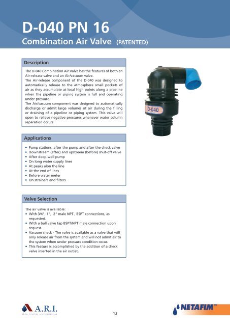
Description<br />
The D-<strong>040</strong> <strong>Combination</strong> <strong>Air</strong> <strong>Valve</strong> has the features of both an<br />
<strong>Air</strong>-release valve and an <strong>Air</strong>/vacuum valve.<br />
The <strong>Air</strong>-release component of the D-<strong>040</strong> was designed to<br />
automatically release to the atmosphere small pockets of<br />
air as they accumulate at local high points along a pipeline<br />
when the pipeline or piping system is full and operating<br />
under pressure.<br />
The <strong>Air</strong>/vacuum component was designed to automatically<br />
discharge or admit large volumes of air during the filling<br />
or draining of a pipeline or piping system. This valve will<br />
open to relieve negative pressures whenever water column<br />
separation occurs.<br />
Applications<br />
• Pump stations: after the pump and after the check valve<br />
• Downstreem (after) and upstreem (before) shut-off valve<br />
• After deep-well pump<br />
• On long water supply lines<br />
• At peaks alon the line<br />
• At the end of lines<br />
• Before water meter<br />
• On strainers and filters<br />
<strong>Valve</strong> Selection<br />
The air valve is available:<br />
• With 3/4", 1", 2" male NPT , BSPT connections, as<br />
requested.<br />
• With a ball valve tap BSPT/NPT male connection upon<br />
request.<br />
• Vacuum check - The valve is available as a valve that will<br />
only release air from the system and will not admit air to<br />
the system when under pressure condition occur.<br />
• This feature is accomplished by the addition of a check<br />
valve inserted in the air outlet.<br />
13
D-<strong>040</strong> <strong>PN</strong> <strong>16</strong><br />
<strong>Combination</strong> <strong>Air</strong> <strong>Valve</strong> (PATENTED)<br />
Operation<br />
The air & vacuum component, with the large orifice,<br />
discharges air at high flow rates during the filling of the<br />
system and admits air into the system at high flow rates<br />
during its drainage and at water column seperation.<br />
High velocity air, should not blow the float shut. Water will<br />
life the float and cause sealing of the valve.<br />
At any time during system operation, should internal<br />
pressure of the system fall below atmospheric pressure,<br />
air will re-enter the systems, preventing down-surge and<br />
cavitation.<br />
The smooth release of air prevents pressure surges and<br />
other destructive phenomena.<br />
Admitting air in response to negative pressure protects<br />
the system from destructive vacuum conditions, prevents<br />
damage caused by water column separation. <strong>Air</strong> re-entry is<br />
essential to efficiently drain the system.<br />
The automatic small orifice air release component releases<br />
entrapped air in the pressurized systems.<br />
Pockets of accumulated air may cause the following<br />
destructive phenomena:<br />
• Impediment of effective flow and hydraulic conductivity<br />
of the system along with a throttling effect<br />
as would a partially closed valve. In extreme cases this will<br />
cause complete flow stoppage.<br />
• Accelerate cavitation damages.<br />
• High pressure surges.<br />
• Accelerate corrosion of metal parts.<br />
• Danger of high-energy burst of compressed air.<br />
• Inaccuracies in flow metering.<br />
As the system starts to fill, the valve functions according to<br />
the following stages:<br />
1. Entrapped air is released by the valve<br />
2. Liquid enters the valve, lifting the float which draws the<br />
"seal plug" to its sealing position.<br />
3. Entrapped air, which accumulates at peaks along<br />
the system (where combination air valves should be<br />
installed), rises to the top of the valve, which in turn<br />
displaces the liquid in the valve's body.<br />
4. The float descends, peeling the "rolling seal", the smaller<br />
orifice opens and the accumulated air is released.<br />
5. Liquid penetrates into the valve and the float rises<br />
unrolling the rolling seal to its sealing position.<br />
When internal pressure falls below atmospheric pressure<br />
(negative pressure):<br />
1. Both orifices will be immediately unplugged and the<br />
float drops away.<br />
2. <strong>Air</strong> is admitted to the system.<br />
Main Features<br />
Working pressure range: 0.2-<strong>16</strong> bar (3-230<br />
psi.) Testing pressure: 25 bar (360 psi.)<br />
• Working Temperature: 60° C<br />
Maximum instantaneous working<br />
temperature: 90° C<br />
• Light, simple and reliable structure.<br />
• Prevents premature closing:<br />
The valve discharges air at high velocity,<br />
exceeding 11 psi differential pressure.<br />
• The orifice of the automatic continuous<br />
acting valve is larger than in any other<br />
air release valve of it's kind, therefore it<br />
discharges air at higher flow rates.<br />
• The size of the automatic orifice makes<br />
its obstruction by debris most unlikely.<br />
• The valve design - rolling seal<br />
mechanism: is less sensitive to pressure<br />
differentials than a direct float seal. It<br />
accomplishes this by having a comparably<br />
large orifice for a wide pressure range<br />
(up to <strong>16</strong> bar).<br />
• The body is made of high strength<br />
plastic, and all operating parts are made<br />
of specially selected corrosion resistant<br />
materials.<br />
• Due to its light weight, the valve may<br />
be installed on plastic piping systems, as<br />
well as other lightweight piping.<br />
• A threaded drainage outlet enables<br />
removal of excess fluids (1 1/2" in the 2",<br />
3/8" in the 3/4", 1")<br />
14
D-<strong>040</strong> <strong>PN</strong> <strong>16</strong><br />
<strong>Combination</strong> <strong>Air</strong> <strong>Valve</strong> (PATENTED)<br />
Project (tender) Specification<br />
Type <strong>Combination</strong> air valve<br />
Operation<br />
-Kinetic component<br />
The valve must discharge air at high velocity during filling of the system and admit air during its drainage. The<br />
valve should be designed to prevent premature closing and discharge air.<br />
-Automatic component<br />
The valve will release accumulated air from the system while it is under pressure and operating.<br />
Large dimension automatic orifice of at least 804 mm² ,attached to the air & vacuum orifice making it less prone<br />
to obstruction by debris.<br />
The same orifice for a wide pressure range (up to <strong>16</strong> bar).<br />
Pressure - 0.2-<strong>16</strong> bar (3-230 psi.)<br />
Testing pressure: 25 bar (360 psi.)<br />
Ends 3/4", 1", 2" male threads NPT, BSP.<br />
Body material Reinforced nylon.<br />
Drainage outlets For easy removal of excess fluids.<br />
Accessories<br />
Ball <strong>Valve</strong><br />
Shut-off valve<br />
Made of brass ATSM B-124<br />
Suitable for: D-<strong>040</strong> 1" 2", D-<strong>040</strong>-C 1" 2"<br />
Flanges<br />
Made of reinforced nylon / cast nylon<br />
Suitable for: D-<strong>040</strong> 1" 2", D-<strong>040</strong>-C 1" 2"<br />
Diameter 40/50/60 Internal threads: 3/4" 1" 2"<br />
Diameter 40/50/65 Internal threads: 3/4" 1" 2"<br />
Diameter 80 Internal threads: 2" 3"<br />
Freeze Jacket<br />
Made of polyurethan<br />
Model one way<br />
The D-<strong>040</strong> air valve is available:<br />
D<strong>040</strong>-V -With a vacuum guarding, out-only<br />
attachment, which only allows air discharge, not<br />
allowing air intake (all models).<br />
D-<strong>040</strong>-I -With a vacuum breaking, In-only<br />
attachment, which only allows air intake, not<br />
allowing air discharge (D-<strong>040</strong> 2" only).<br />
D-<strong>040</strong>-NS -With a non-slam, discharge-throttling<br />
attachment, which allows free air intake, but<br />
throttles air discharge (D-<strong>040</strong> 2" only).<br />
15
D-<strong>040</strong> <strong>PN</strong> <strong>16</strong><br />
<strong>Combination</strong> <strong>Air</strong> <strong>Valve</strong> (PATENTED)<br />
Dimensions and Weights<br />
<strong>Air</strong> and Vacuum Flow Rate<br />
Model<br />
1”, 3/4”<br />
Dim. mm<br />
Weight<br />
Orifice Area<br />
(mm2)<br />
Gr.<br />
A B C Auto. Kin.<br />
D-<strong>040</strong> P 100 143 3/8” BSP 0.33 7.8 100<br />
D-<strong>040</strong> B 100 143 3/8” BSP 0.70 7.8 100<br />
D-<strong>040</strong> ST. 100 143 3/8” BSP 0.65 7.8 100<br />
D-<strong>040</strong> ST.ST. 100 143 3/8” BSP 1.40 7.8 100<br />
2”<br />
D-<strong>040</strong>-P 180 209 1½” BSP 1.1 12 804<br />
D-<strong>040</strong>-B 180 209 1½” BSP 2.2 12 804<br />
D-<strong>040</strong>-ST. 180 209 1½” BSP 2.1 12 804<br />
D-<strong>040</strong> ST.ST. 180 209 1½” BSP 3.1 12 804<br />
Automatic <strong>Air</strong> Discharge<br />
Parts list and specification<br />
No.<br />
Part<br />
Material<br />
D-<strong>040</strong> P / B / ST D-<strong>040</strong> ST ST<br />
1. Body Reinforced Nylon St.St. SAE 3<strong>16</strong><br />
2. Drainage Elbow Polypropylene Polypropylene<br />
3. Seal Plug Assembly<br />
3a. Screws Stainless Steel Stainless Steel<br />
3b. Plug Cover Reinforced Nylon Polypropylene<br />
3c. Rolling Seal E.P.D.M. Viton<br />
3d. Plug Reinforced Nylon Polypropylene<br />
4. Clamping Stem Reinforced Nylon Polypropylene<br />
5. Float Foamed Polypropylene<br />
6. O-Ring BUNA-N Viton<br />
7. Base Reinforced Nylon St.St. SAE 3<strong>16</strong><br />
/ Brass ASTM B124<br />
/ St.St. SAE 3<strong>16</strong><br />
Optional Ball valve Brass ASTM B124<br />
<strong>16</strong>