download - TERMAN
download - TERMAN
download - TERMAN

You also want an ePaper? Increase the reach of your titles
YUMPU automatically turns print PDFs into web optimized ePapers that Google loves.
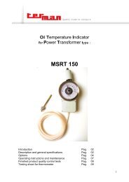
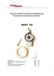
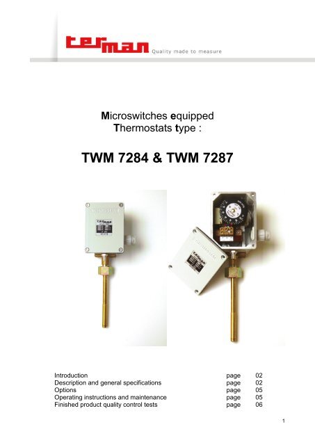
Microswitches equipped<br />
Thermostats type :<br />
TWM 7284 & TWM 7287<br />
Introduction<br />
Description and general specifications<br />
Options<br />
Operating instructions and maintenance<br />
Finished product quality control tests<br />
page<br />
page<br />
page<br />
page<br />
page<br />
02<br />
02<br />
05<br />
05<br />
06<br />
1
Introduction.<br />
These instruments are designed to control the temperature of the insulating oil inside power transformer<br />
tanks and they can fitted with one or two change-over microswitches suitable to control cooling equipments<br />
and / or protection circuits (alarm and trip) of the transformer.<br />
Also a version with 1 contact with fully adjustable differential ( min/max version ) is available in order to consent<br />
the set of the switching on and switching off points.<br />
The component designs of our instruments are protected by :<br />
ITALIAN PATENT No. 208603<br />
ITALIAN PATENT No. 89113<br />
E.E.C. PATENT No. 0245212<br />
U.S. PATENT No. 4,727,227<br />
Effectiveness of these instruments must be stressed, both as regards commutation precision and extreme<br />
simplicity of operation.<br />
Special attention has been paid to design of each single part resulting in extreme high reliability of our instruments<br />
and ensuring long-lasting accurate operating. We have designed the setting system, the mounting<br />
devices and the dimensions of the casing to consent the operator to easily install the thermostat and to save<br />
time in setting and making cable layout.<br />
Besides the exact constructional and severe quality control we adopt, the high performances of our instruments<br />
are further assured by the employ of the best products supplied by European technology’s more advanced<br />
company names. In particular :<br />
the MICROSWITCH SETTING UNIT is mounted on 2 micro ball bearings to reduce the frictions and to<br />
grant right working under vibrations;<br />
the AWG 22 CABLES we adopt are silver plated and protected with Teflon according to MIL - W -<br />
16878-4 Standard;<br />
the TERMINAL BLOCKS (WEIDMULLER - Germany) grant very high performances and are certified in<br />
accordance with European standards;<br />
<br />
<br />
the POWDER PAINT grants protection against corrosion and increases the insulation of the device;<br />
the SENSING SPRING TUBE is manufactured with a special bronze alloy that avoid any plastic deformation<br />
and histeresis of the spring.<br />
Description and general specifications.<br />
Temperature sensing system : expansion type compensated for ambient temperature changes by means<br />
of a built-in compensating device.<br />
To avoid to many checks after setting into works and periodical recalibrations we adopt particular cares in<br />
testing the components. In particular the sensing system is subject to 3 different tests :<br />
1. vacuum test : the sensing system is connected to a vacuum plant. The plant pressure is decreased to<br />
2x10 -3 mbar (hpa) to verify the quality of the welding and the porosity of the material;<br />
2. pressure test : the sensing system is put under pressure up to 280 bar to verify the welding and that the<br />
spring is not subject to any deformation;<br />
3. overheating test : after being completed, the sensing system bulbs are located in a heating plant controlled<br />
by a microprocessor based temperature monitoring system. The temperature is increased up to a<br />
value that is 20% more than the maximum range value of the sensing systems ( i.e. for a thermostat<br />
whose range is 0/150°C the overheating test temperature is 180°C ). The temperature remains at that<br />
value for 8 hours in this way simulating 1 year life under normal working conditions ( i.e. for a thermostat<br />
whose range is 0/150°C ---> 110°C ). In this way we train the spring and verify that the precision remains<br />
the same.<br />
2
Capillary tube protection : steel + PVC armouring / stainless steel armouring / rilsan tubing.<br />
Bulb : bronze.<br />
Casing : aluminium alloy powder painted (RAL 7035) suitable to withstand to any climate and to heavy polluted<br />
atmosphere in as well tropical or arctic climates (-40 / +70°C). All components are made of corrosion<br />
resistant or surface treated materials. The case is provided with a breather device to avoid dew inside of the<br />
case.<br />
Mechanical protection degree : IP 65.<br />
Standard ranges :<br />
0 / 120°C; -20 / +130°C; 0 / +150°C; -20 / +140°C; 0 / +160°C; -50 / +150°C; 0 / 180°C; 0 / +200°C.<br />
Commutation tolerance : 2% of full scale value.<br />
Commutation differential : 4% of full scale value.<br />
On customer’s request the differential can be increased.<br />
On request it is possible to have the version with 1 contact with adjustable differential (min max version ). In<br />
this case you have 1 contact and two setting pointers. The first one (red color) to set the switching on temperature.<br />
The second one ( green color ) to set the switching off temperature. The differential is so adjustable<br />
from a minimum of 4% to a maximum of 50% of full scale value.<br />
Insulation : 2000V 50Hz between terminals and earth for a 60 seconds time.<br />
MICROSWITCHES MAKING AND BREAKING CAPACITY :<br />
STANDARD MICROSWITCHES HIGH-PERFORMANCE MICROSWITCHES<br />
VOLTAGE RESISTIVE LOAD INDUCTIVE LOAD RESISTIVE LOAD INDUCTIVE LOAD<br />
125 VAC 5 A 5 A 10 A 10 A<br />
250 VAC 5 A 5 A 10 A 10 A<br />
30 VDC 5 A 3 A 10 A 10 A<br />
50 VDC 1 A 1 A 3 A 2,5 A<br />
75 VDC 0,75 A 0,25 A 1 A 0,5 A<br />
125 VDC 0,5 A 0,1 A 0,5 A 0,1 A<br />
250 VDC 0,25 A 0,1 A 0,25 A 0,1 A<br />
3
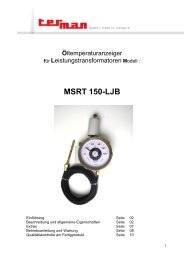
THERMOSTAT type TWM 7284<br />
THERMOSTAT type TWM 7287<br />
4
Options.<br />
Elastic suspension (Drwg. No.1231) : it’s a vibration damping system able to minimize the effects of a machine<br />
vibrations on the instrument.<br />
Earthquake proof version : by equipping the instrument with the elastic suspension and suitable internal<br />
components.<br />
Operating instructions and maintenance.<br />
Mounting : mount the instrument on its machine or plant.<br />
If the thermostat is provided with capillary tube is possible to supply the same with the following connections:<br />
rigid locking screw M14 located on the top of the thermostat;<br />
elastic suspension (Drwg. 1231) that is mounted on the top of the thermostat and has a screw M14 that<br />
consents to install the instrument to the plant.<br />
Remove the thermostat case cover : by unscrewing the 4 stainless steel screws.<br />
Cable layout : the numerations 1-2 indicate the microswitches progression (red, blue pointer). Close to the<br />
terminals you will find the following abbreviations :<br />
• C = common<br />
• NO = normally open<br />
• NC = normally closed<br />
that allow the operator to choose the desired cable layout.<br />
Connect the microswitches terminals and the earth terminal.<br />
After having done all the connecting operations re-position the terminal box cover taking care to put the flat<br />
gasket in the right position and screwing the 4 stainless steel screw.<br />
Setting : to set microswitches pls., follow exactly the instructions :<br />
remove the thermostat case cover;<br />
stop the microswitches setting dial (small black dial) with two fingers and slide the frictioned microswitches<br />
setting pointers until they are located at the desired temperature. Note that to reduce errors<br />
you have to slide the pointers towards higher temperature value;<br />
Replace the thermostat case cover.<br />
5
Finished product quality control tests.<br />
Instrument calibration : carried out through thermostatic baths controlled by a computer system. The procedure<br />
varies according to instruments scale.<br />
Example of procedure for a thermostat whose scale is -20 / +130°C : the calibration is made using 5 different<br />
baths set at the following temperatures :<br />
bath 1 = -20°C<br />
bath 2 = 20°C<br />
bath 3 = 50°C<br />
bath 4 = 100°C<br />
bath 5 = 125°C<br />
Calibration procedure :<br />
Step 1: a check is carried out to see whether the temperature taken by the instrument under test differs from<br />
that taken through the sample sensor by more than the 70% of the maximum allowed instrument<br />
reading tolerance value.<br />
This test is performed by sequentially plunging the thermostat’s bulb into successive temperature increasing<br />
thermostatic baths: -20°C / +20°C / +50°C / +100°C / +125°C.<br />
Step 2: the instrument is heated until the rotation of the sensing system exceeds by 20% the angular full<br />
scale value.<br />
Step 3: step 1 is repeated, but inversely.<br />
Microswitches actuation test : performed through a computer controlled testing unit.<br />
The bulb is immersed in a thermostatic bath. The computer changes the temperature inside the bath and by<br />
means of suitable sensors verifies the commutation tolerance, the commutation differential, the electrical circuits<br />
of each microswitch.<br />
At the end of the test a test report is directly printed by the computer.<br />
Check of instrument mechanical protection degree : IP 65.<br />
This test is carried out by means a lance-sprinkled water jet on all sides of device.<br />
Insulation test : carried out by means of a microprocessor controlled testing unit.<br />
Note : all the collected data are immediately transferred, by means of the computer net, to the quality control<br />
and to the design departments to be supervised and evaluated.<br />
In our files, we keep all the above mentioned informations and we can supply to the customer detailed reports<br />
regarding the performances of each instrument .<br />
I EDITION AUGUST 2006<br />
Terman '90 S.r.l., Via Ghisalba, 13-20/21, 20021 Bollate (MI) – Italy. Tel: +39 02 38 30 37 12, Fax: +39 02 38 30 37 19,<br />
E-Mail info@terman.com, www.terman.com<br />
C.F./P. IVA IT 09970270154 – C.C.I.A.A. 1332904 – Trib. Milano Reg. Soc. 302729 – Cap. Soc. € 119.000<br />
6