BLZ MS 251 - HEB Hydraulik - Elementebau GmbH
BLZ MS 251 - HEB Hydraulik - Elementebau GmbH
BLZ MS 251 - HEB Hydraulik - Elementebau GmbH

You also want an ePaper? Increase the reach of your titles
YUMPU automatically turns print PDFs into web optimized ePapers that Google loves.
<strong>BLZ</strong><strong>MS</strong><strong>251</strong>-8-2011<br />
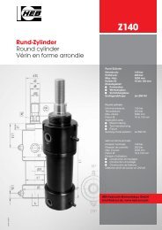
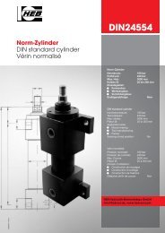
<strong>Hydraulik</strong>-Blockzylinder<br />
Block cylinders<br />
Vérins blocs<br />
<strong>BLZ</strong> <strong>MS</strong> <strong>251</strong><br />
Typ: Block-Zylinder<br />
Nenndruck: 250 bar<br />
Prüfdruck: 350 bar<br />
Max. Hub: 500 mm<br />
Kolben Ø: 20 bis 63 mm<br />
Einsatzgebiet:<br />
• Formenbau<br />
• Werkzeugbau<br />
• Vorrichtungsbau<br />
Endlagenabfrage: Ja<br />
Type: Block cylinder<br />
Nominal pressure: 250 bar<br />
Test pressure: 350 bar<br />
Max. stroke: 500 mm<br />
Piston Ø: 20 to 63 mm<br />
Application area:<br />
• Mould-making<br />
• Tool manufacturing<br />
• Fixture<br />
Sensing of end position: Yes<br />
Type: Vérin bloc<br />
Pression nominale: 250 bar<br />
Pression de contrôle: 350 bar<br />
Max. Course: 500 mm<br />
Piston Ø: 20 à 63 mm<br />
Domain d’utilisation:<br />
• Construction de moulages<br />
• Construction d’outillage<br />
• Construction de fixations<br />
Détection de fin de course: Oui<br />
<strong>HEB</strong> <strong>Hydraulik</strong>-<strong>Elementebau</strong> <strong>GmbH</strong><br />
info@heb-zyl.de, www.heb-zyl.com
Allgemeine Beschreibung<br />
und Hinweise<br />
•<br />
•<br />
•<br />
Die kontinuierlich einstellbare Abfrage der Kolbenposition<br />
erfolgt über seitlich – Zylinderseite<br />
2 und 4 – in einer Nut montierte Magnetsensoren,<br />
die das Magnetfeld des im Zylinder laufenden<br />
Kolbens erfassen. Durch Verschieben<br />
der Sensoren sind beliebige Schaltpunkte über<br />
den kompletten Zylinderhub frei einstellbar.<br />
Zwei Magnetfeldsensoren – für Betriebs- und<br />
Umgebungstemperaturen von -20˚C bis +70˚C<br />
– mit LED-Anzeige und jeweils 3 m Kabel sowie<br />
lösbarer Steckverbindung nach ca. 100 mm,<br />
gehören zum Lieferumfang. Sensortausch ohne<br />
Neujustierung und ohne Neuverdrahtung<br />
möglich.<br />
Zylindergehäusewerkstoff hochfeste Alu-Legierung<br />
(niedriges Gewicht).<br />
Kolbenstangenlauffläche hartverchromt, geschliffen<br />
und poliert.<br />
• Kolben Ø 20 mm bis 63 mm<br />
•<br />
•<br />
Hübe (Toleranz nach DIN/ISO 2768m) gem.<br />
Tabelle Seite 4.<br />
Hubbegrenzung durch vordere und hintere Anschlagfläche,<br />
bei Kolbengeschwindigkeiten<br />
über 0,1m/sec. ist externe Hubbegrenzung zu<br />
empfehlen.<br />
• Kolbenstangendichtung PU/Nutring.<br />
•<br />
•<br />
Kolbendichtung PTFE/ Gleitring<br />
(statisch nicht dicht).<br />
Die eingebauten Dichtungen sind für Hydroflüssigkeiten<br />
H, HL, HLP, nach DIN 51524 /<br />
51525 und den Temperaturbereich von -20˚C<br />
bis +105˚C geeignet.<br />
Achtung!<br />
Um Schaltfehler zu vermeiden muß ein den Zylinder<br />
umgebendes Fremdmagnetfeld kleiner<br />
als 1kA/m sein. Es darf sich kein ferritisches<br />
Material in unmittelbarer Nähe der Magnetsensoren<br />
befinden. Gegen ferritische Späne müssen<br />
Abdeckungen vorgesehen werden. Bei selten<br />
auftretenden Schaltproblemen (aufgrund<br />
von Störfeldern) kann der Einsatz von V2A<br />
Schrauben nötig sein. Die Umgebungstemperatur<br />
darf +70°C nicht überschreiten. Höhere Temperaturen<br />
siehe Sonderausstattungen Seite 3.<br />
Nicht geeignet zur Betätigung von Schnitt-und<br />
Stanzwerkzeugen.<br />
General description<br />
and instructions<br />
Magnetic field sensors, mounted in grooves on<br />
the side faces (faces 2 and 4) of the cylinder, indicate<br />
the position of the piston. The sensors are<br />
steplessly adjustable, and react to a magnet fitted<br />
in the piston. By sliding the sensors in their<br />
grooves, the switching points can be set at will<br />
anywhere along the stroke of the cylinder. The two<br />
magnetic field sensors are suitable for ambient<br />
temperatures ranging from -20˚C to +70˚C. They<br />
have LED indicators, and 3 metres of cable each.<br />
There are connectors ca. 100 mm from the sensors,<br />
so that it is possible to change the sensors<br />
without re-adjustment or re-wiring.<br />
The cylinder body is made of high- strength aluminium<br />
alloy for low weight.<br />
The piston rod is hard-chromium plated, ground<br />
and polished.<br />
The piston diameters range from 20 mm to 63 mm.<br />
Strokes are given in the table on page 4 (tolerances<br />
to DIN/ISO 2768m).<br />
The stroke is limited by contact surfaces at both<br />
ends. For piston speeds above 0,1m/s, we recommend<br />
that the stroke is limited externally.<br />
Piston rod seal: PU ring in groove.<br />
Piston seal: PTFE support ring, not statically<br />
oil-tight.<br />
The seals installed are suitable for types H, HL,<br />
and HLP hydraulic fluids to DIN 51524 / 51525,<br />
and temperatures between -20˚C and +105˚C .<br />
Warning!<br />
To prevent switching errors, the cylinder must not<br />
be installed in an external magnetic field that exceeds<br />
1kA/m. There must be no feeritic material<br />
in the immediate neighbourhood of the sensors.<br />
Covers must be provided to protect against ferritic<br />
swarf. With switching problems which can occur<br />
scarcely, the use of stainless steel screws<br />
may be applicable. The ambient temperature<br />
must not exceed +70°C. Higher temperatures<br />
please see special equipments page 3.<br />
Not suitable for use of cutting and stamping tools.<br />
Description et informations<br />
générales<br />
La détection réglable en continue de la position du<br />
piston s’effectue par l’intermédiaire de capteurs magnétiques,<br />
montés latéralement - côté 2 ou 4 du cylindre<br />
- dans une rainure, qui détectent le champ<br />
magnétique du piston se déplaçant dans le cylindre.Le<br />
déplacement des capteurs permet de régler librement<br />
n’importe quel point de contact sur toute la<br />
course du piston. Deux capteurs magnétiques - pour<br />
des températures ambiantes de -20°C à +70°C - à<br />
affichage à DEL ainsi que, pour chaque capteur, un<br />
câble de 3 m et un connecteur détachable, situé à<br />
100 mm du capteur, sont inclus dans la livraison.<br />
Possibilité d’échanger les capteurs sans nouveau<br />
réglage ni nouveau câblage.<br />
Carter du cylindre en alliage alu haute résistance (faible<br />
poids).<br />
Surface d’usure de la tige de piston chromée dur<br />
meulée et polie.<br />
Ø piston: de 20 mm à 63 mm<br />
Courses (tolérance selon norme DIN/ISO 2768m ):<br />
voir tableau page 4.<br />
Limitation de la course par surface d’arrêt avant et<br />
arrière. Pour des vitesses de piston supérieures à 0,1<br />
m/s, il est recommandé d’utiliser un limiteur de course<br />
externe.<br />
Joint de la tige de piston; joint en U à lèvres en PU.<br />
Joint du piston: joint à anneau glissant en téflon (les<br />
joints statiques ne sont pas étanches).<br />
Les joints intégrés sont appropriés pour les liquides<br />
hydrauliques H, HL, HLP, selon les normes DIN<br />
51524 / 51525 et pour des températures de -20°C<br />
à +105°C.<br />
Attention!<br />
Afin d’éviter toute de contact, aucun champ magnétique<br />
extérieur supérieur à 1kA/m ne doit entourer<br />
le cylindre. Aucun matériau ferritique ne doit se<br />
trouver directement à proxximité des capteurs magnétiques.<br />
Prévoir des protections contre les copeaux<br />
ferritiques. Des problèmes de connection<br />
peuvent survenir dans certain cas (champ brouilleur).<br />
L'utilisation de vis acier inoxydable sout à conseiller.<br />
La température ambiante ne doit pas être<br />
supérieure à +70°C. Temperature superior voir equipements<br />
spéciaux page 3 .<br />
Non appropié pour la commande d’outils de découpage<br />
et de poinçonnage.<br />
Technische Daten Technical data Caractéristiques techniques<br />
Kolben Ø mm • Piston Ø mm • Ø piston mm 20 25 32 40 50 63<br />
Kolbenstangen Ø mm • Piston-rod Ø mm • Ø tige de piston mm 12 16 20 25 32 40<br />
Kolbenfläche (stoßend) (AK ) cm2<br />
piston face (pushing) • de piston (poussante)<br />
3.14 4.91 8.04 12.56 19.63 31.16<br />
Kolbenringfläche (ziehend) (A R ) cm2<br />
Piston ring face (drawing action), Surface du segment de piston (tirant)<br />
Kraft (A K ) daN • Force • Force<br />
Kraft (A R ) daN • Force • Force<br />
2<br />
120 bar<br />
160 bar<br />
200 bar<br />
250 bar<br />
120 bar<br />
160 bar<br />
200 bar<br />
250 bar<br />
2.00 2.90 4.90 7.65 11.59 18.60<br />
376 589 964 1500 2350 3730<br />
502 785 1280 2000 3140 4980<br />
628 982 1600 <strong>251</strong>0 3920 6230<br />
785 1220 2010 3140 4900 7790<br />
240 348 588 918 1390 2230<br />
320 464 784 1220 1850 2970<br />
400 580 980 1530 2310 3720<br />
500 725 1220 1910 2890 4650<br />
<strong>HEB</strong> <strong>Hydraulik</strong>-<strong>Elementebau</strong> <strong>GmbH</strong> • Tel. (0761) 1 30 99-0, Fax (0761) 13 50 66<br />
<strong>BLZ</strong> <strong>MS</strong> <strong>251</strong>
<strong>BLZ</strong> <strong>MS</strong> <strong>251</strong><br />
Funktionsart <strong>BLZ</strong> <strong>MS</strong> <strong>251</strong> Mode of operation Mode de fonctionnement<br />
Sinnbild DIN/ISO 1219/1<br />
Symbol<br />
Symbol<br />
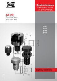
Sonderausstattungen special equipements equipements spéciaux<br />
• Beidseitige Entlüftungsschrauben für Schlauchanschluß On both sides venting screws for flexible tube connection<br />
Sur le deux côtés vis de sortie d’air pour raccord de tuyau<br />
• Kolbenstangenlauffläche gehärtet und hartverchromt ab Kolbendurchmesser 40mm<br />
Piston-rods hardened and hard-chrome plated from piston diameter 40mm<br />
Tiges de piston trempées et chromée durement diamètre du piston à partir de 40mm<br />
• Standardhub begrenzt. Sämtliche Maße gemäß Standardhub (bitte beachten!)<br />
Reduced standard stroke. All dimensions according to standard stroke. (Please take notice!)<br />
Courses standardisées limitées. Toutes les dimensions selon course standardisée (en tenir compte s.v.p!)<br />
• Kolben statisch dicht Piston with static sealing effect<br />
Piston avec effet hermétique<br />
• Korrosionsbeständige Ausführung in V2A, Werkstoff 1.4301.<br />
Corrosion-resistant version in stainless steel, mat. no. 1.4301.<br />
Modèle rèsistant à la corrosion en acier inoxydable, matériau numeró 1.4301<br />
• Magnetfeldsensoren bis +130°C Magnetic field sensors for +130°C<br />
Capteurs magnétiques pour +130°C<br />
• Stangenseitiger Zentrierbund Rod-side with centering collar<br />
Côté tige avec collet de centrage<br />
• Kolbenstangenende mit Außengewinde Piston-rod with external thread<br />
Fin de la tige de piston avec filet extérieur<br />
• Nut zur Justierung des <strong>Hydraulik</strong>-Zylinders standard N4 - N2 nach Kundenwunsch N4.1 - N2.1<br />
Groove for adjustmen standard N4 - N2 wishes of the customers N4.1 - N2.1<br />
Rainure pour ajustement standard N4 - N2 désir du client N4.1 - N2.1<br />
• Die Maße zu Kolbenstangenende B1 und M1 können nach Kundenwunsch geändert werden. Unter der Zusatzbezeichnung B1.1 bei<br />
Angabe der Maßeinheiten L8, L7, d5 oder unter der Bezeichnung M1.1 bei Angabe der Maßeinheiten L3, L15, d1.<br />
The dimensions B1 and M1 to the end of the piston rod can be changed on request. By the use of the additional code B1.1 please give<br />
the dimensions L8, L7 and d5, or the additional code M1.1 with the dimensions L3, L15 and d1.<br />
Les dimensions jusqu’à la fin de la tige du piston B1 et M1 sont modifiables à la demande du client, indiquer B1.1 pour les dimensions L8, L7 et d5, ou M1.1<br />
pour les dimensions L3, L15 et d1.<br />
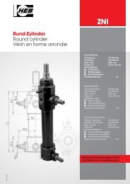
Zentrierbund „ZE“<br />
centering collar<br />
collet de centrage<br />
Bezeichnung<br />
Order specification<br />
Référence de<br />
commande<br />
206<br />
Beschreibung Description Description<br />
Doppeltwirkend Double-acting à double effet<br />
Kolbenstangenende mit Außengewinde<br />
„B1“<br />
Piston-rod end with external thread.<br />
Fin de la tige de piston avec filet<br />
extérieur.<br />
Kolben Ø mm • Piston Ø mm • Ø tige de piston mm 20 25 32 40 50 63<br />
d 10 f7 29 35 43 50 63 79<br />
L20 2 2 3 3 3 3<br />
L15 7 10 12 15 17 18<br />
d5 M8 M10 M12 M16 M20 M27<br />
L7 16 20 22 25 35 50<br />
L8 23 30 34 40 52 68<br />
b N9 8 10 12 12 14 20<br />
t 2 2 3 3 5 5<br />
h Bauform • Construction form • Mode de construction 1 / 1.1 / 1.2 34 38 38 40 44 50<br />
Bauform • Construction form • Mode de construction 6 / 6.1 40 41 41 40 44 55<br />
auch nach Kundenwunsch möglich (N4.1 / N2.1) • can be changed on request • modifiables à la demande du client<br />
e-mail: info@heb-zyl.de / homepage: http://www.heb-zyl.com<br />
Nut „N4 - N2“ (N4.1 - N2.1)<br />
Groove „N4 - N2“ (N4.1 - N2.1)<br />
Rainure „N4 - N2“ (N4.1 - N2.1)<br />
S7<br />
S13<br />
S29<br />
S35<br />
S41<br />
S55<br />
ZE<br />
B1<br />
3
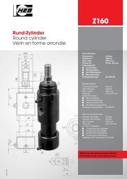
Baumaße <strong>BLZ</strong> <strong>MS</strong> <strong>251</strong> Construction measures Mesures de construction<br />
Kolben Ø mm • Piston Ø mm • Ø piston mm 20 25 32 40 50 63<br />
Stangen- Ø mm d2 • Piston-rod Ø mm d2 • Ø tige de piston mm d2 12 16 20 25 32 40<br />
A G 1/4 G 1/4 G 1/4 G 1/4 G 1/4 G 1/2<br />
b1 25 30 35 40 45 65<br />
b2 40 45 55 63 75 95<br />
b3 40 50 55 63 76 95<br />
b4 60 65 75 85 100 125<br />
b5 12 15 19 23 28 36<br />
c1 11 11 13 13 13 17<br />
c2 4 4 5 5 5 9<br />
c3 11 11 13 13 13 17<br />
c4 4 4 5 5 5 9<br />
d1 M8 M10 M12 M16 M20 M27<br />
d3 6,5 8,5 10,5 10,5 13 17<br />
d4 6,5 8,5 10,5 10,5 13 17<br />
d8 11,5 15 19 24 31 39<br />
d9 6,5 6,5 8,5 8,5 8,5 10,5<br />
e1 44 50 58 66 80 100<br />
e2 22 25 29 33 40 50<br />
SW 10 13 17 22 27 36<br />
L0 (+ Hub) • (+ stroke) • (+ course) 66 65 70 77 88 100<br />
L2 34 38 38 40 44 50<br />
L3 19 25 28 35 30 40<br />
L5 21 23 22 24 27 26<br />
L6 16 17 20 25 27 32<br />
L9 11 12 14 18 20 25<br />
L15 7 10 12 15 17 18<br />
L24 12 16 20 20 24 32<br />
L27 12 12 16 16 16 20<br />
L28 11 12 14 18 20 25<br />
L29 25 26 24 24 27 31<br />
m3 M6 M8 M10 M10 M12 M16<br />
m4 M6 M8 M10 M10 M12 M16<br />
m9 M6 M6 M8 M8 M8 M10<br />
O- Ring 7x1,5 7x1,5 8x2 8x2 8x2 12x2<br />
Achtung! Zur Vermeidung von Fehlschaltungen der Magnetsensoren ist grundsätzlich folgender Mindesthub einzuhalten:<br />
Attention! To avoid faulty switching of the sensors, one must keep at all times a minimum stroke of:<br />
Attention! Pour éviter faux couplage il est indispensable de respecter une course minimale comme suite:<br />
Mindesthub / Min.stroke / course min. 6 6 6 6 8 10<br />
Übersicht der lieferbaren<br />
Standardhübe<br />
Kolben Ø mm<br />
piston Ø mm<br />
Ø piston mm<br />
Standardhübe<br />
standard strokes<br />
courses standardisées<br />
Summary Table of the<br />
deliverable standard strokes<br />
Zwischenhübe sind durch werkseitig montierte Begrenzungshülsen lieferbar.<br />
For intermediate strokes, spacers can be installed in our works.<br />
Possibilité de course intermédiaires par montage d’usine de manchons limiteurs de course.<br />
4<br />
* L0 und /and / et L6 und /and / et L9 + 9mm<br />
**L0 und /and / et L6 und /and / et L9 + 10mm<br />
20 25 32 40 50 63<br />
20 20 20 20 - -<br />
- 30 30 30 30 30<br />
40 - 40 40 - -<br />
- 50 50 50 50 50<br />
60 - 60 60 60 60<br />
80 80 80 80 80 80<br />
- 100 100 100 100 100<br />
- * 120 - 120 - 120<br />
- - ** 130 - 130 -<br />
<strong>HEB</strong> <strong>Hydraulik</strong>-<strong>Elementebau</strong> <strong>GmbH</strong> • Tel. (0761) 1 30 99-0, Fax (0761) 13 50 66<br />
Aperçu sur les modes de<br />
courses standardisées<br />
<strong>BLZ</strong> <strong>MS</strong> <strong>251</strong>
<strong>BLZ</strong> <strong>MS</strong> <strong>251</strong><br />
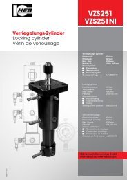
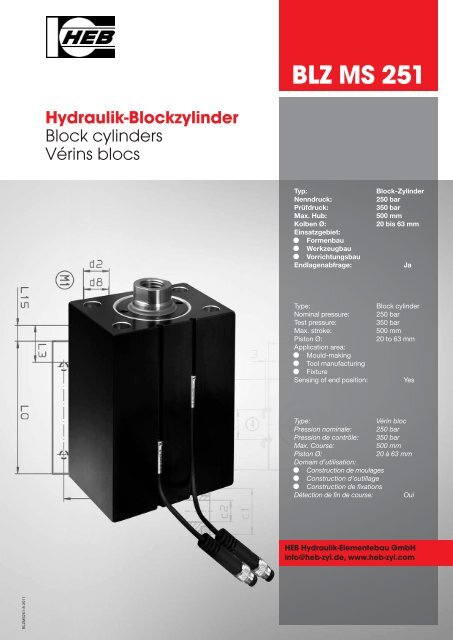
Bauformen construction forms modes de construction<br />
Zylinderseite - page ① ... ④<br />
Zylinderseite - page ① ... ④<br />
Zylinderseite - page ① ... ④<br />
Zylinderseite - page ① ... ④<br />
Senkung DIN 74-K<br />
Counterbore....<br />
noyure pour....<br />
Bauform<br />
construction form<br />
mode de construction<br />
Bauform<br />
construction form<br />
mode de construction<br />
Bauform<br />
construction form<br />
mode de construction<br />
Bauform<br />
construction form<br />
mode de construction<br />
e-mail: info@heb-zyl.de / homepage: http://www.heb-zyl.com<br />
2 Querbohrungen, ab 160 bar ist<br />
Abstützung erforderlich<br />
2 cross holes, from 160 bar a support<br />
is necessary<br />
1<br />
2 forures transversales, à partir de 160 bar<br />
un support est nécessaire<br />
2 Gewindebohrungen, ab 160 bar ist<br />
Abstützung erforderlich<br />
2 thread borings, from 160 bar a support<br />
is necessary<br />
2 alésages filetés, à partir de 160 bar<br />
un support est nécessaire<br />
4 Längsbohrungen, kolbenseitig mit<br />
Senkung für DIN EN ISO 4762<br />
4 longitudinal holes, piston-side with<br />
counterbore for DIN EN ISO 4762<br />
1.1<br />
1.2<br />
2<br />
4 forures longitudinales, côté piston avec<br />
noyure pour DIN EN ISO 4762<br />
4 Gewindebohrungen stangenseitig<br />
4 thread borings, rod-side<br />
4 alésages filetés, côté tige<br />
2.1<br />
5
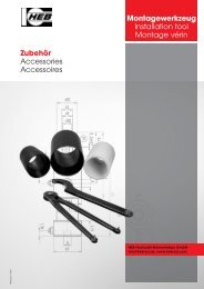
Bauformen construction forms modes de construction<br />
6<br />
Senkung DIN 74-K<br />
Counterbore....<br />
noyure pour....<br />
Zylinderseite - page ① ... ④<br />
Zylinderseite - page ① ... ④<br />
Zylinderseite - page ① ... ④<br />
Zylinderseite - page ① ... ④<br />
Einzelheit Z<br />
detail, détail<br />
Einzelheit Z<br />
detail, détail<br />
Bauform<br />
construction form<br />
mode de construction<br />
4 Längsbohrungen, stangenseitig mit<br />
Senkung für DIN EN ISO 4762<br />
Bauform<br />
construction form<br />
mode de construction<br />
Bauform<br />
construction form<br />
mode de construction<br />
Bauform<br />
construction form<br />
mode de construction<br />
<strong>HEB</strong> <strong>Hydraulik</strong>-<strong>Elementebau</strong> <strong>GmbH</strong> • Tel. (0761) 1 30 99-0, Fax (0761) 13 50 66<br />
3<br />
4 longitudinal holes, rod-side with counterbore<br />
for DIN EN ISO 4762<br />
4 forures longitudinales, côté tige avec<br />
noyure pour DIN EN ISO 4762<br />
4 Gewindebohrungen kolbenseitig<br />
4 thread borings, piston-side<br />
4 alésages filetés, côté piston<br />
3.1<br />
4 Durchgangsbohrungen, Anschlüsse auf<br />
der Breitseite mit Senkung für<br />
O-Ring-Abdichtung zum Anflanschen an<br />
Verteilerplatte<br />
6<br />
4 through holes, connections at the broadside<br />
with lowering for o-ring seal forthe<br />
flanging at the distribution plate<br />
4 alésages de passage, raccords à la côté<br />
large avec abaissement pour joint torique<br />
pour brider à la table de distribution<br />
6.1<br />
4 Gewindebohrungen, Anschlüsse auf der<br />
Breitseite mit Senkung für O-Ring-Abdichtung<br />
zum Anflanschen an Verteilerplatte<br />
4 thread borings, connections at the broadside<br />
with lowering for o-ring seal for the<br />
flanging at the distribution plate<br />
4 alésages filetés, raccords à la côté large<br />
avec abaissement pour joint torique pour<br />
brider à la table de distribution<br />
<strong>BLZ</strong> <strong>MS</strong> <strong>251</strong>
<strong>BLZ</strong> <strong>MS</strong> <strong>251</strong><br />
Bauformen construction forms modes de construction<br />
Zylinderseite - page ① ... ④<br />
Zylinderseite - page ① ... ④<br />
Senkung DIN 74-K<br />
Counterbore....<br />
noyure pour....<br />
Zylinderseite - page ① ... ④<br />
Zylinderseite - page ① ... ④<br />
Senkung DIN 74-K<br />
Counterbore....<br />
noyure pour....<br />
Senkung DIN 74-K<br />
Counterbore....<br />
noyure pour....<br />
Einzelheit Z<br />
detail, détail<br />
Einzelheit Z<br />
detail, détail<br />
Einzelheit Z<br />
detail, détail<br />
Einzelheit Z<br />
detail, détail<br />
Ansicht X, view, vue<br />
Ansicht X<br />
view, vue<br />
Bauform<br />
construction form<br />
mode de construction<br />
4 Axialbohrungen, Anschlüsse stangenseitig<br />
mit Senkung für O-Ring-Abdichtung<br />
zum Anflanschen an Verteilerplatte<br />
(Verschlußschraube DIN 988)<br />
Bauform<br />
construction form<br />
mode de construction<br />
Bauform<br />
construction form<br />
mode de construction<br />
Bauform<br />
construction form<br />
mode de construction<br />
e-mail: info@heb-zyl.de / homepage: http://www.heb-zyl.com<br />
7<br />
4 axial borings, connections rod-side with<br />
lowering for o-ring seal for the flanging at<br />
the distribution plate (screw plug DIN 988)<br />
4 forures axiales, raccords à la côté tige avec<br />
abaissement pour joint torique pour brider à<br />
la table de distribution<br />
(vis de fermeture DIN 988)<br />
7.1<br />
4 Gewindebohrungen, Anschlüsse stangenseitig<br />
mit Senkung für O-Ring-Abdichtung<br />
zum Anflanschen an Verteilerplatte<br />
(Verschlußschraube DIN 988)<br />
4 thread borings, connections rod-side with<br />
lowering for o-ring seal for the flanging at<br />
the distribution plate (screw plug DIN 988)<br />
4 alésages filetés, raccords à la côté tige<br />
avec abaissement pour joint torique pour<br />
brider à la table de distribution<br />
(vis de fermeture DIN 988)<br />
4 Axialbohrungen, Anschlüsse bodenseitig<br />
mit Senkung für O-Ring-Abdichtung<br />
zum Anflanschen an Verteilerplatte<br />
4 axial borings, connections bottom side<br />
with lowering for o-ring seal for the flanging<br />
at the distribution plate<br />
4 forures axiales, raccords côté fond avec<br />
abaissement pour joint torique pour brider à<br />
la table de distribution<br />
8<br />
8.1<br />
4 Gewindebohrungen, Anschlüsse bodenseitig<br />
mit Senkung für O-Ring-Abdichtung<br />
zum Anflanschen an Verteilerplatte<br />
4 thread borings, connections bottom side<br />
with lowering for o-ring seal for the flanging<br />
at the distribution plate<br />
4 alésages filetés, raccords côté fond avec<br />
abaissement pour joint torique pour brider à<br />
la table de distribution<br />
7
Technische Daten zum Magnetfeldsensor Typ BMF 10-C2-S<br />
Technical data for the magnetic field sensor Typ BMF 10-C2-S • Caracteristiques techniques pour les capteurs magnétiques Typ BMF 10-C2-S<br />
8<br />
Betriebsspannung Supply voltage Tension d’emploi 10.....30 V DC<br />
Umgebungstemperatur Ambient operation temperature Temperature d’emploi -25°C...+70°C<br />
Ausgangsbetriebsstrom Output current Courant de sortie 200mA<br />
Spannungsabfall Ud Voltage drop Ud Chute de tension Ud 2V<br />
Stromaufnahme Current consumption Courant absorbé < 15mA<br />
Ausgangsschaltung Output signal sortie de la mise en circuit pnp<br />
Schaltfunktion Switchung function Fonctionnement de la mise Schließer / Normally<br />
open / Ouverture normal<br />
Verpolschutz Protected against polarity rev. irréversibilité de poles ja / yes / oui<br />
Kurzschlussschutz Short circuit protection Protection contre courtscircuits ja / yes / oui<br />
Anschlußart Connection type Raccordement Pu-Flex-Kabel,<br />
Schutzart Protection class Degré de protection IP67<br />
3x0,25 mm 2 x 3000mm<br />
Bestellbezeichnung Order specification Référence de commande Artikel-Nr.: t14903<br />
Typenschlüssel Code Clé des types<br />
Zylindertyp • Cylinder type • Type de vérin<br />
Schalterposition / Zylinderseite • Sensor position • Position du commutateur<br />
Betriebsdruck • Operating pressure • Pression de service<br />
Bauform • Construction form • Mode de construction<br />
Kolben Ø mm • Piston Ø mm • Ø piston mm<br />
Kolbenstangen Ø mm • Piston-rod Ø mm • Ø Tige de piston mm<br />
Hub • Stroke • Course<br />
Funktionsart • Mode of operation • Mode de fonctionnement<br />
Kolbenstangenende Standard • Piston-rod end standard • Fin de la tige de piston standard<br />
Sonderausstattung • Special equipments • Equipements spéciaux<br />
<strong>BLZ</strong> <strong>MS</strong> 2 <strong>251</strong> 2 50 32 60 206 M1 S7-4<br />
Bestellbeispiel Example of order Exemple de commande<br />
<strong>BLZ</strong> <strong>MS</strong> 2 - <strong>251</strong> - 2 - 50 / 32 / 60 - 206 / M1 / S7-4<br />
<strong>HEB</strong>-Blockzylinder<br />
für Betriebsdruck bis 250 bar,<br />
mit externer, verstellbarer Positionsabfrage<br />
in Verbindung mit Magnetfeldsensoren auf<br />
Zylinderseite 2,<br />
Bauform 2 (4 Längsbohrungen),<br />
Kolben Ø 50 mm, Kolbenstangen Ø 32 mm,<br />
Hub 60 mm.<br />
206 = doppeltwirkend<br />
M1 = Kolbenstangenende Standard<br />
S7-4= beidseitige Entlüftungsschrauben<br />
Blockzylindergehäuse Seite 4<br />
Änderungen vorbehalten.<br />
Subject to change without notice.<br />
Modification resérvée.<br />
aktive Fläche / active face / surface active<br />
<strong>HEB</strong> bloc cylinder<br />
for operating pressure up to 250 bar,<br />
with external, adjustable inquiry of position<br />
in connection with magnetic field sensors<br />
on cylinder-side 2,<br />
Construction form 2, (4 longitudinal holes),<br />
Piston Ø 50 mm, Piston-rod Ø 32 mm,<br />
Stroke 60 mm.<br />
206 = double acting<br />
M1 = Piston-rod end standard<br />
S7-4= venting screws, block cylinder<br />
housing side 4<br />
<strong>HEB</strong> vérin bloc<br />
pour pression de fonctionnement jusqu’-á<br />
250 bar, avec demande de position externe<br />
et variable en connection avec capteurs<br />
magnétiques - côté 2 du cylindre -<br />
Mode de construction 2, (4 forures longitudinales),<br />
Ø Piston 50 mm, Ø tige de piston<br />
32 mm, Course 60 mm.<br />
206 = à effet double<br />
M1 = Fin de la tige de piston standard<br />
S7-4= vis de sortie d’air, vérin bloc côté 4<br />
Achtung - Typenbezeichnung bzw. Ident.Nr. sowie Kom.Nr. bei Ersatzbeschaffung und<br />
Ersatzteilbezug unbedingt angeben.<br />
Attention - In case of order and purchase of spare parts it is absolutely necessary to indicate<br />
the order specification or the number of identification as well as the commission number.<br />
Attention - En cas d’acquisition des éléments de rechange indiquer absolutement la référence<br />
de commande ou bien le numéro d’identification ainsi que le numéro de commission<br />
<strong>HEB</strong> <strong>Hydraulik</strong>-<strong>Elementebau</strong> <strong>GmbH</strong> • Postfach 10 0117 • D - 79120 Freiburg<br />
<strong>BLZ</strong> <strong>MS</strong> <strong>251</strong>