Air Star Comfort 20 / 30 - Air Star AB
Air Star Comfort 20 / 30 - Air Star AB
Air Star Comfort 20 / 30 - Air Star AB

Create successful ePaper yourself
Turn your PDF publications into a flip-book with our unique Google optimized e-Paper software.
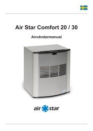
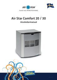
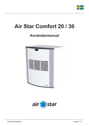
<strong>Air</strong> <strong>Star</strong> <strong>Comfort</strong> <strong>20</strong>/<strong>30</strong><br />
Fresh air with HEAT RECOVERY<br />
<strong>Air</strong> <strong>Star</strong> <strong>Comfort</strong> <strong>20</strong> / <strong>30</strong><br />
User Manual
Contents <strong>Air</strong> <strong>Star</strong> <strong>Comfort</strong> <strong>20</strong>/<strong>30</strong><br />
Picking list 3<br />
Technical data 3<br />
<strong>Comfort</strong> <strong>20</strong> 3<br />
<strong>Comfort</strong> <strong>30</strong> 3<br />
Use 4-5<br />
Safety precautions 4<br />
<strong>Comfort</strong> <strong>20</strong>/<strong>30</strong> 4<br />
Opening and closing front door 4<br />
Setting air change rate 5<br />
Setting temperature 5<br />
LEDs 5<br />
Assembly 6-8<br />
Location of ventilator <strong>Comfort</strong> <strong>20</strong>/<strong>30</strong> 6<br />
Equipment & tools 6<br />
Components 6<br />
Safety precautions 7<br />
Fixed installation 7<br />
Work sequence for assembly directly on wall 7<br />
Work sequence for assembly recessed in wall 8<br />
Maintenance 9-10<br />
Opening ventilation unit 10<br />
Removing and installing ventilator 10<br />
Cleaning the ventilator 10<br />
Replacing the filter 10<br />
Assembly drawing 11<br />
Warranty & complaints 12<br />
User Manual 2 Version 1.6
Picking list <strong>Air</strong> <strong>Star</strong> <strong>Comfort</strong> <strong>20</strong>/<strong>30</strong><br />
1 x <strong>Air</strong> <strong>Star</strong> <strong>Comfort</strong> <strong>20</strong>/<strong>30</strong> with 1.4 m<br />
power cable.<br />
1 x Spiro pipe, ø 100 mm, L = <strong>20</strong>0 mm<br />
1 x door opener<br />
1 x edge strip<br />
2 x supply air filters<br />
2 x exhaust air filters<br />
(Not pictured)<br />
Technical data<br />
<strong>Comfort</strong> <strong>20</strong> <strong>Comfort</strong> <strong>30</strong><br />
<strong>Air</strong> change rate m 3 : 16-32 m 3<br />
<strong>Air</strong> change rate l/s: 4.44-8.89 l/s<br />
Rated power:<br />
825 W<br />
Mains connection: 2<strong>30</strong>-240 V<br />
Fans (run alternately): 10-25 W<br />
Heating element: 0-800 W<br />
<strong>Air</strong> change rate m 3 : <strong>20</strong>-48 m 3<br />
<strong>Air</strong> change rate l/s: 5.56-13.33 l/s<br />
Rated power:<br />
8<strong>30</strong> W<br />
Mains connection: 2<strong>30</strong>-240 V<br />
Fans (run alternately): 10-<strong>30</strong> W<br />
Heating element: 0-800 W<br />
User Manual 3 Version 1.6
Use<br />
<strong>Air</strong> <strong>Star</strong> <strong>Comfort</strong> <strong>20</strong>/<strong>30</strong><br />
Safety precautions<br />
• Be sure to unplug the power cord to the ventilator before you handle it.<br />
• Remember that the electrical coil and heat exchanger may be hot after use.<br />
• Always wait 15 minutes therefore after shutdown before you open the ventilator.<br />
Ventilator <strong>Comfort</strong> <strong>20</strong>/<strong>30</strong><br />
1<br />
2 3<br />
1. Holes for door opening<br />
2. Communication window<br />
3. Exhaust air duct<br />
4. Supply air duct<br />
4<br />
1<br />
Opening and closing front door<br />
Use the supplied door opener to open the ventilator, push it down in the hole (1) for the door<br />
opening. To turn off the ventilator properly, press until you hear a click. Make sure the power<br />
cord is positioned in the slot at the bottom of the door and that it is not pinched when the<br />
door is closed.<br />
Användarhandbok User Manual 4 4 Version 1.6 1.5
Use<br />
<strong>Air</strong> <strong>Star</strong> <strong>Comfort</strong> <strong>20</strong>/<strong>30</strong><br />
Setting air change rate<br />
Adjust the air change rate as required using the top control. The scale above<br />
the control is adjusted to suit the area the room unit is intended for. The<br />
minimum value for the scale corresponds to an air change rate of 16 m 3 /h for<br />
<strong>Comfort</strong> <strong>20</strong>, and <strong>20</strong> m 3 /h for <strong>Comfort</strong> <strong>30</strong>. The maximum value corresponds to<br />
an air change rate of 32 m 3 /h for <strong>Comfort</strong> <strong>20</strong>, and 48 m 3 /h for <strong>Comfort</strong> <strong>30</strong>. You<br />
can use the remote control (option) to make the air change settings.<br />
Note: Do you have problems with radon or allergies? If so, contact a radon ad<br />
viser who can provide information on the degree of ventilation you need.<br />
Setting temperature<br />
To set the temperature you need a thermometer. Place the thermometer<br />
in an arbitrary place in the room. Regulate the temperature on the ventilator<br />
using the control. Fine-tune for about 1-2 days until the temperature is<br />
reached.<br />
Note: In a room that is > 10 m 2 the unit alone cannot maintain <strong>20</strong> 0 C during the winter<br />
months.<br />
You can use the remote control (option) to make the temperature settings. The minimum<br />
value for the scale corresponds to about 10 0 C and the maximum value is about 26 0 C.<br />
LEDs<br />
At the top of the ventilator there is a black communication window with a LED behind it that<br />
lights to indicate various activities and events:<br />
• A green glowing LED indicates that the heating element is turned on.<br />
• A green flashing LED means communication with the remote control.<br />
• A red flashing LED means you are updating a setting on the unit.<br />
Användarhandbok User Manual 55 Version 1.61.5
Assembly<br />
<strong>Air</strong> <strong>Star</strong> <strong>Comfort</strong> <strong>20</strong>/<strong>30</strong><br />
<strong>Air</strong> <strong>Star</strong> <strong>Comfort</strong> <strong>20</strong>/<strong>30</strong> can be installed in two ways. Recessed into the wall is the preferred method<br />
in environments with high demands on aesthetics, and where the wall structure requires this. Directly<br />
on the inside of the interior wall provides the simplest installation and has the same function. Page 11<br />
features a drawing of the outer box with all dimensions. The dimensions of the outer box are 290 x 340<br />
mm; add 10-15 mm for the insulation when mounting the <strong>Comfort</strong> <strong>20</strong>/<strong>30</strong> recessed into the wall.<br />
Location of ventilator <strong>Comfort</strong> <strong>20</strong>/<strong>30</strong><br />
Before mounting the unit, determine the location. Please note the following points before starting the<br />
installation:<br />
• Make sure that there is nothing on the outside of the building where the ventilation grill is to be<br />
installed.<br />
• Take the wall studs into account.<br />
• Locate the power lines.<br />
• Do not place the ventilator so that it ends up behind furniture or anything that reduces the air<br />
change rate.<br />
• For high placement of the ventilator, the top of the outer box should be at least 10 cm from the<br />
ceiling, bearing in mind the unit draws in air from above and in order to ensure access to open<br />
the door with the door opener.<br />
• Remember that in order to open the door properly, you need to make sure you have at least a<br />
10 cm gap to the nearest wall.<br />
• The length of the Spiro pipe must be no more than 1 metre.<br />
• Try placing the ventilator under or at the side of a window.<br />
• The bottom edge of the outer box should be <strong>20</strong>-<strong>30</strong> cm above the floor.<br />
• Make sure the power cord is long enough to lift the ventilator from the outer box.<br />
• Mount high up in a shower room and basement.<br />
Equipment & tools<br />
Stud finder<br />
Folding rule<br />
Spirit level<br />
Driller<br />
Drill Ø12-15mm<br />
Tiger saw<br />
Hammer<br />
Respiratory protection<br />
Vacuum cleaner<br />
Components<br />
Outer box<br />
Spiro pipe<br />
Ventilation unit<br />
Heat exchanger cassette<br />
User Manual 6 Version 1.6
Assembly<br />
<strong>Air</strong> <strong>Star</strong> <strong>Comfort</strong> <strong>20</strong>/<strong>30</strong><br />
Safety precautions<br />
• The unit must not be placed under an electric socket!<br />
• The ventilator must not be covered. Overheating risk!<br />
• Do not place the ventilation unit behind furniture or in any other manner that reduces<br />
circulation throughout the room.<br />
• Wear respiratory protection when you install the ventilator recessed in concrete walls.<br />
• A maximum of three units should be connected to a single fuse block 10A.<br />
• It is recommended not to add any additional load to the same fuse group.<br />
Fixed installation<br />
• For fixed installation (no plug), an all-pole switch must be mounted before the unit<br />
by a qualified electrician.<br />
Warning!<br />
• In order to avoid overheating, do not cover the heater.<br />
• The heater must not be located immediately bellow a socket outlet.<br />
Work sequence for assembly directly on wall<br />
1. Place the outer box against the wall and plot the circular bushing on the outer box’s back piece,<br />
adjusting the hole to the sleeve diameter and depth (sleeve dimensions Ø 123 mm and 41 mm<br />
deep). Drill the remainder of the holes with Ø 100 mm + 10-15 mm of insulation.<br />
2. Drill and cut the opening for the wall bushing. Remember that the Spiro pipe must not be longer<br />
than 1 m horizontally.<br />
3. Measure and cut the pipe to the correct length. Insert and secure the Spiro pipe. The black rubber<br />
seal on the pipe must be facing the outer box sleeve.<br />
4. Installation of the outer box. <strong>Star</strong>t by drilling four attachment holes in the box’s back piece. Use a<br />
screw (and plug, if needed) suited for the wall.<br />
Use vibration damping material between the attachment points on the box and the wall. Ensure<br />
that the vibration damping material is not compressed too much and loses its function. (Risk of<br />
structure-borne sound in the wall). Push the Spiro pipe into the outer box sleeve.<br />
5. Clean the inside of the outer box before putting the ventilator in place. Carefully slide the unit<br />
so that the ventilator sleeve goes into the slot on the outer box sleeve.<br />
6. Connect the plug to the wall socket.<br />
<strong>Comfort</strong> <strong>20</strong>/<strong>30</strong> is now installed and ready for operation. Go to chapter: Use for setting the unit.<br />
User Manual 7 Version 1.6
Assembly<br />
<strong>Air</strong> <strong>Star</strong> <strong>Comfort</strong> <strong>20</strong>/<strong>30</strong><br />
Work sequence for assembly recessed in wall<br />
1. The ventilation unit must be mounted horizontally. Mark the dimensions on the wall.<br />
Outer box dimensions are width: 290 and height: 340 mm. Add 10-15 mm for insulation.<br />
2. Drill a hole with a diameter 12-15 mm in each corner. Check the wall studs and any<br />
wires. Stagger the placement if necessary.<br />
3. Cut with tiger saw. Deepen the recess to a depth suited to the wall structure. The outer<br />
box depth is <strong>20</strong>4 mm. The maximum recommended recess depth is 180 mm.<br />
4. Important! Calculate the holes for the outer box so that there is room for at least <strong>30</strong> mm<br />
of insulation between the exterior wall and the back of the outer box.<br />
5. Separate the ventilator from the outer box. Now slide the outer box into the opening and<br />
align with a spirit level.<br />
6. Mark the location of the Spiro pipe on the remaining exterior wall using a circular bushing<br />
on the outer box’s back piece. Adapt the holes to suit the sleeve diameter and depth.<br />
(Sleeve dimensions Ø 123 mm and 41 mm deep). The remainder of the holes are drilled<br />
with Ø 100 mm + 10-15 mm of insulation around the Spiro pipe.<br />
7. Now remove the outer box and drill the holes for the Spiro pipe.<br />
8. Measure and cut the Spiro pipe to the correct length. Insert and fix the pipe in the proper<br />
position, the black rubber seal on the pipe should be facing the outer box sleeve. Finish by<br />
insulating around the pipe.<br />
9. Installation of the outer box can be made with screw attachment or by fixing with sealing<br />
foam.<br />
10. Slide in the outer box and press the Spiro tube into the outer box sleeve. Make sure the<br />
outer box is horizontal and vertical. Attach using a wooden wedge. At the screw attach<br />
ments, drill attachment holes in the outer box at the locations corresponding to the wall<br />
structure.<br />
11. Screw or join the outer box to the wall so that it is secure. The screw attachment is always<br />
used with vibration damping material between the outer box and the wall. Make sure<br />
that the vibration damping material is not compressed too much and loses its function.<br />
(Risk of structure-borne sound in the wall).<br />
12. Insulate around the outer box, and finish by fitting the cover frame (option). Before the<br />
assembly of the exterior wall grill, check that insulation has been placed around the pipe.<br />
13. Clean the inside of the outer box before putting the ventilator in place. Carefully slide the<br />
unit so that the ventilator sleeve goes into the slot on the outer box sleeve. Connect the<br />
plug to the wall socket.<br />
<strong>Comfort</strong> <strong>20</strong>/<strong>30</strong> is now installed and ready for operation. Go to chapter: Use for<br />
setting the unit.<br />
User Manual 8 Version 1.6
Maintenance<br />
<strong>Air</strong> <strong>Star</strong> <strong>Comfort</strong> <strong>20</strong>/<strong>30</strong><br />
7<br />
1<br />
Ventilator<br />
2<br />
3<br />
4<br />
5<br />
1. Motor compartment<br />
2. Front cover<br />
3. Control for air change rate<br />
4. Control for temperature<br />
5. Connection for door cable<br />
6. Outlet for power cable<br />
7. Exhaust air duct<br />
8. Supply air duct<br />
8<br />
6<br />
Safety precautions<br />
• Before cleaning the ventilator, ensure that it is not connected to the mains.<br />
• The ventilator has a heating element. Wait about 15 minutes after the ventilator has<br />
been disconnected before starting to clean.<br />
• Be sure to wear respiratory protection for protection against dust.<br />
• The ventilator must not be rinsed with water.<br />
Warning!<br />
• If the power cord is damaged, it must be replaced by the manufacturer, its service<br />
agent or similarly qualified persons in order to avoid any hazards.<br />
User Manual 9 Version 1.6
Maintenance<br />
<strong>Air</strong> <strong>Star</strong> <strong>Comfort</strong> <strong>20</strong>/<strong>30</strong><br />
Opening the ventilation unit<br />
Unplug the power cord. When you need to open the ventilation unit, it is recommended to grip the top of<br />
the front cover (2) and pull it towards you. There is a joint at the bottom edge that secures the front door<br />
so that it cannot be removed. To close, just lift the cover and press it to its original position.<br />
Removing and installing the ventilator<br />
Open the ventilation unit’s front door as instructed on page. 4. Now grip the top of the front cover (2) and<br />
gently pull it out.<br />
Cleaning the ventilator<br />
Open the door of the <strong>Comfort</strong> <strong>20</strong>/<strong>30</strong> by pushing at the same time as inserting the door opener into the<br />
hole at the top of the door. Carefully disconnect the cable connection from the door. Open the cover on<br />
the ventilator by gripping the top and pulling towards you. Remove the heat exchanger cassette. Vacuum<br />
or dust inside the ventilator, cover and the heat exchanger cassette.<br />
For thorough cleaning, you may want to remove the unit from the outer box. Before refitting the ventilator<br />
in the outer box, this should also be cleaned.<br />
Replacing the filter<br />
1. 2. 3. 4.<br />
To obtain the best efficiency, the supply air and exhaust air filters need to be replaced regularly, at least<br />
twice a year. If the units are placed in a very dirty environment, the filters must be replaced more often.<br />
When the front cover on the ventilation unit is opened, for the <strong>Comfort</strong> models this is done by<br />
inserting the accompanying red needles into the small hole on the left side, on top of the ventilator cover.<br />
1. An exhaust air filter is located on the top edge of the front.<br />
2. Remove it from the Velcro strip and replace it with a new one.<br />
3. Grip the top edge of the ventilator, fold down the front of the ventilation unit and remove the heat exchanger.<br />
4. Lift the cover and grill to access the supply air filter.<br />
It is a good idea to use a vacuum cleaner and vacuum the corrugated board in the heat exchanger, and vacuum<br />
and wipe the exposed parts of the unit with a damp cloth. This increases the unit’s life span considerably!<br />
Note: Make sure the cover on the heat exchanger cassette is facing upwards when refitting in the ventilation unit.<br />
• Standard filter BG/160-65, not cleanable.<br />
• Dust filter EG/150-65, not cleanable.<br />
• Pollen filter EF/<strong>30</strong>0-45, not cleanable. (Only available as option).<br />
User Manual 10 Version 1.6
Assembly drawing<br />
<strong>Air</strong> <strong>Star</strong> <strong>Comfort</strong> <strong>20</strong>/<strong>30</strong><br />
For the holes, add 10-15 mm to the external dimensions for insulation.<br />
297<br />
340<br />
Ø 122,5<br />
41<br />
<strong>20</strong>4<br />
<strong>20</strong>4<br />
81,5<br />
290<br />
User Manual 11 Version 1.6
Warranty & complaints<br />
<strong>Air</strong> <strong>Star</strong> <strong>Comfort</strong> <strong>20</strong>/<strong>30</strong><br />
Warranty<br />
<strong>Air</strong> <strong>Star</strong> gives a 5 year factory warranty on its products to private individuals.<br />
For businesses and public institutions, a two-year warranty applies.<br />
For the warranty to be valid, maintenance must be carried out, i.e. changing<br />
the filter and cleaning performed in compliance with the instructions in the<br />
manual. If maintenance is neglected or filters have been replaced with models<br />
that are not genuine parts, the warranty is void.<br />
A receipt or invoice must always be presented in connection with warranty<br />
matters.<br />
Complaints<br />
In order to claim that goods are defective (concerning transportation damage,<br />
see below), the business customer must file a complaint with <strong>Air</strong> <strong>Star</strong> <strong>AB</strong> immediately,<br />
although no later than <strong>30</strong> days from the invoice date and return the<br />
items in some way. A consumer (individual) must report the defect within a<br />
reasonable time after the defect has been identified.<br />
Business customers must check all goods on arrival to verify that the goods<br />
are flawless. If the complaint is received after 10 days, <strong>Air</strong> <strong>Star</strong> <strong>AB</strong> reserves<br />
the right in relation to the business customer to determine if the defect is to<br />
be corrected. In relation to a consumer (individual), <strong>Air</strong> <strong>Star</strong> <strong>AB</strong> will correct the<br />
defect at its own expense, if this can be done without unreasonable cost or inconvenience<br />
to <strong>Air</strong> <strong>Star</strong> <strong>AB</strong>. In all other matters we refer you to the Consumer<br />
Purchases Act. See also below regarding responsibility for defects.<br />
For claims, the customer must contact <strong>Air</strong> <strong>Star</strong> <strong>AB</strong>’s customer service by<br />
telephone +46 60-15 39 10, e-mail to info@airstar.se, stating order and invoice<br />
number and the reason for the complaint. A consumer (individual) should<br />
use a prepaid way bill provided by <strong>Air</strong> <strong>Star</strong> <strong>AB</strong> for the return of the goods. The<br />
goods should be submitted within 14 days from the receipt of the way bill.<br />
When returning the goods, the invoice and order slip along with a description<br />
of the defect, preferably in detail, must accompany the goods. Returns must<br />
be returned in their original packaging, well packed in packaging approved<br />
by the Post Office (e.g. brown corrugated cardboard). Any transport damage<br />
resulting from inadequate packaging will be charged to the customer. <strong>Air</strong> <strong>Star</strong><br />
<strong>AB</strong> reserves the right to inspect the goods and charge a testing fee of SEK<br />
350 plus VAT if the goods are shown not to be defective and the claim is not<br />
accepted.<br />
Friskluft med VÄRMEÅTERVINNING<br />
<strong>Air</strong> <strong>Star</strong> <strong>AB</strong><br />
Montörvägen 10, SE-853 50 Sundsvall sweden<br />
Tel 060-15 39 10 fax 060-15 39 11<br />
www.airstar.se<br />
12