- Page 1 and 2:
Garney Construction 785 E Warren Ga
- Page 3 and 4:
SUBMITTALS https://projectdox.frees
- Page 5 and 6:
Garney Construction 785 E Warren Ga
- Page 7 and 8:
Page 173 Page 174 Page 179 Page 179
- Page 10 and 11:
Ward County Water Supply Expansion
- Page 12 and 13:
1513188 HP Page 1 of 5 401 South Hi
- Page 14 and 15:
1513188 HP Page 3 of 5 401 South Hi
- Page 16 and 17:
1513188 HP Page 5 of 5 401 South Hi
- Page 18 and 19:
1513188 HP Page 2 of 5 401 South Hi
- Page 20 and 21:
1513188 HP Page 4 of 5 401 South Hi
- Page 65 and 66:
AWWA Butterfly Valves 3" - 20" Engi
- Page 67 and 68:
Scope of Line: AWWA In-Plant Rubber
- Page 69 and 70:
Features and Benefits: of Pratt Mod
- Page 71 and 72:
Dimensional Data: Model 2FII, Flang
- Page 73 and 74:
401 S. Highland Avenue Aurora, Illi
- Page 75 and 76:
3" through 20" Butterfly Valves Sco
- Page 77 and 78:
Design Details: Models 511A and 510
- Page 79 and 80:
Suggested Specification for the Hen
- Page 81 and 82:
Actuator Dimensional Data for Model
- Page 83 and 84:
Figure 511 24" - 72" Class 150 B Fl
- Page 85 and 86:
PRATT PRODUCT GUIDE Model 2FII Mono
- Page 87 and 88:
401 S. Highland Avenue Aurora, Illi
- Page 89 and 90:
A Tradition of Excellence With the
- Page 91 and 92:
Scope of Line: Triton XR-70 Butterf
- Page 93 and 94:
Design Details: Triton XR-70 Butter
- Page 95 and 96:
E-Lok Seat Design Years of Reliable
- Page 97 and 98:
Water Flow Characteristics Proven P
- Page 99 and 100:
Valve End Types and Dimensions: Mec
- Page 101 and 102:
Actuation Traveling Nut Type Manual
- Page 103:
401 S. Highland Avenue Aurora, Illi
- Page 106 and 107:
SCOPE OF THE LINE: PRATT HP250II B
- Page 108 and 109:
THE HENRY PRATT SEAT ON BODY DESIGN
- Page 110 and 111:
HP250II 3"- 20", DUCTILE IRON BODY
- Page 112 and 113:
401 S. Highland Avenue Aurora, Illi
- Page 114 and 115:
Suggested Specification: Butterfly
- Page 116 and 117:
6" - 24" HP350 Mechanical Joint End
- Page 118 and 119:
3”-20” 2FII & Groundhog® Bonde
- Page 120 and 121:
3”-20” 2FII & Groundhog® Bonde
- Page 122 and 123:
3”-20” 2FII & Groundhog® Bonde
- Page 124 and 125:
3”-20” 2FII & Groundhog® Bonde
- Page 126 and 127:
3”-20” 2FII & Groundhog® Bonde
- Page 128 and 129:
3”-20” 2FII & Groundhog® Bonde
- Page 130 and 131:
Triton XR-70,Triton XL & Groundhog
- Page 132 and 133:
Triton XR-70,Triton XL & Groundhog
- Page 134 and 135:
Triton XR-70,Triton XL & Groundhog
- Page 136 and 137:
Triton XR-70,Triton XL & Groundhog
- Page 138 and 139:
Triton XR-70,Triton XL & Groundhog
- Page 140 and 141:
Triton XR-70,Triton XL & Groundhog
- Page 142 and 143:
Triton XR-70,Triton XL & Groundhog
- Page 144 and 145:
24”-48” HP250II Butterfly Valve
- Page 146 and 147:
24”-48” HP250II Butterfly Valve
- Page 148 and 149:
24”-48” HP250II Butterfly Valve
- Page 150 and 151:
24”-48” HP250II Butterfly Valve
- Page 152 and 153:
24”-48” HP250II Butterfly Valve
- Page 154 and 155:
24”-48” HP250II Butterfly Valve
- Page 156 and 157:
HP350 Butterfly Valve 6”-24” (M
- Page 158 and 159:
HP350 Butterfly Valve Table of Cont
- Page 160 and 161:
HP350 Butterfly Valve INSTALLATION
- Page 162 and 163:
HP350 Butterfly Valve TESTING When
- Page 164 and 165:
HP350 Butterfly Valve WARNING Fluid
- Page 166 and 167:
HP350 Butterfly Valve TROUBLESHOOTI
- Page 168 and 169:
HP350 Butterfly Valve Cross Section
- Page 170 and 171:
Diviner Position Indicator SAFETY M
- Page 172 and 173:
Diviner Position Indicator FUNCTION
- Page 174 and 175:
Diviner Position Indicator INSTALLA
- Page 176 and 177:
Diviner Position Indicator HOW TO C
- Page 178 and 179:
PAINT SYSTEM SUMMARY Page 1 of 5 SY
- Page 180 and 181:
Page 3 of 5 UL/FM HENRY PRATT COMPA
- Page 182:
Page 5 of 5 UL/FM HENRY PRATT COMPA
- Page 185 and 186:
A Tradition of Excellence With the
- Page 187 and 188:
MANUAL ACTUATORS Spur G
- Page 189 and 190:
MANUAL ACTUATORS
- Page 191 and 192:
FEATURES & BENEFITS OF THE TRAVELIN
- Page 193 and 194:
ACTUATOR EXTENSIONS
- Page 195 and 196:
ACTUATOR EXTENSIONS
- Page 197 and 198:
ACTUATOR EXTENSIONS
- Page 199 and 200:
ACTUATOR EXTENSIONS
- Page 201 and 202:
ACTUATOR EXTENSIONS
- Page 203 and 204:
ACTUATOR EXTENSIONS
- Page 205 and 206:
ACTUATOR EXTENSIONS
- Page 207 and 208:
PRATT Henry Pratt Company TITLE: OP
- Page 209 and 210:
AUMA Data Sheet AUMA Comm No.: A000
- Page 213 and 214:
GS50.3 GS63.3 GS80.3 GS100.3 GS125.
- Page 215 and 216:
Dimensions Valve postion indicator
- Page 217 and 218:
Technical data valve position indic
- Page 219 and 220:
Technical data valve position indic
- Page 221 and 222:
Technical data valve position indic
- Page 223 and 224:
.
- Page 225 and 226:
.
- Page 227 and 228:
.
- Page 229 and 230:
.
- Page 231 and 232:
.
- Page 233 and 234:
. .
- Page 235 and 236:
. .
- Page 237 and 238:
.
- Page 239 and 240:
. .
- Page 241 and 242:
.
- Page 243 and 244:
.
- Page 245 and 246:
.
- Page 247 and 248:
Anschlusspläne APG Terminal plans
- Page 249 and 250:
Bevel gearboxes GK 10.2 - GK 40.2 O
- Page 251 and 252:
Bevel gearboxes GK 10.2 - GK 40.2 O
- Page 253 and 254:
Bevel gearboxes GK 10.2 - GK 40.2 O
- Page 255 and 256:
Bevel gearboxes GK 10.2 - GK 40.2 O
- Page 257 and 258:
Bevel gearboxes GK 10.2 - GK 40.2 O
- Page 259 and 260:
Bevel gearboxes GK 10.2 - GK 40.2 O
- Page 261 and 262:
Bevel gearboxes GK 10.2 - GK 40.2 O
- Page 263 and 264:
Bevel gearboxes GK 10.2 - GK 40.2 O
- Page 265 and 266:
Bevel gearboxes GK 10.2 - GK 40.2 O
- Page 267 and 268:
Bevel gearboxes GK 10.2 - GK 40.2 O
- Page 269 and 270:
AUMA - wordwide Europe AUMA Riester
- Page 271 and 272:
AUMA Riester GmbH & Co. KG P.O.Box
- Page 273 and 274:
Worm gearboxes GS 50.3 - GS 250.3 O
- Page 275 and 276:
Worm gearboxes GS 50.3 - GS 250.3 O
- Page 277 and 278:
Worm gearboxes GS 50.3 - GS 250.3 O
- Page 279 and 280:
Worm gearboxes GS 50.3 - GS 250.3 O
- Page 281 and 282:
Worm gearboxes GS 50.3 - GS 250.3 O
- Page 283 and 284:
Worm gearboxes GS 50.3 - GS 250.3 O
- Page 285 and 286:
Worm gearboxes GS 50.3 - GS 250.3 O
- Page 287 and 288:
Worm gearboxes GS 50.3 - GS 250.3 O
- Page 289 and 290:
Worm gearboxes GS 50.3 - GS 250.3 O
- Page 291 and 292:
Worm gearboxes GS 50.3 - GS 250.3 O
- Page 293 and 294:
Worm gearboxes GS 50.3 - GS 250.3 .
- Page 295 and 296:
Worm gearboxes GS 50.3 - GS 250.3 O
- Page 297 and 298:
Worm gearboxes GS 50.3 - GS 250.3 O
- Page 299 and 300:
Worm gearboxes GS 50.3 - GS 250.3 O
- Page 301 and 302:
Worm gearboxes GS 50.3 - GS 250.3 O
- Page 303 and 304:
North American Sales and Service: U
- Page 305 and 306:
IQ Electric Motor Actuator Data She
- Page 307 and 308:
IQ Electric Motor Actuator Data She
- Page 309 and 310:
IQ Electric Motor Actuator Data She
- Page 313 and 314:
NOT ROTORK SUPPLY X ACTUATOR TERMIN
- Page 322 and 323:
PRATT Henry Pratt Company TITLE: OP
- Page 324 and 325:
Introduction Rotork’s proven IQ r
- Page 326 and 327:
Actuator electrical specification P
- Page 328 and 329:
Actuator electrical specification P
- Page 330 and 331:
Control specification Interlocks Ex
- Page 332 and 333:
Indication options Indication Optio
- Page 334 and 335:
Actuator circuit diagram - basic IQ
- Page 336 and 337:
Actuator circuit diagrams - number
- Page 338 and 339:
Remote control circuits Remote cont
- Page 340 and 341:
Analogue control circuits Analogue
- Page 342 and 343:
UK head office Rotork Controls Limi
- Page 344 and 345:
The Rotork Setting Tool allows actu
- Page 347 and 348:
CONTENTS Page 1 Health and Safety 2
- Page 349 and 350:
2 Storage 3 Operating your IQ Actua
- Page 351 and 352:
5 3.4 Display-Alarm Indication The
- Page 353 and 354: 4 Preparing Drive Bush 7 4.1 IQ10 t
- Page 355 and 356: 9 Fig. 4.9 Type A Drive Bush in Pos
- Page 357 and 358: 11 5.1 Rising Stem Valves - Top Mou
- Page 359 and 360: 13 5.7 IQML Adjusting Linear Stroke
- Page 361 and 362: 15 6.4 Connecting to Terminals On E
- Page 363 and 364: 17 7.2 The Setting Tool Specificati
- Page 365 and 366: 19 7.7 Procedure Branch - Crossroad
- Page 367 and 368: 21 Viewing the Primary Function Set
- Page 369 and 370: C2 Close Action 23 The actuator can
- Page 371 and 372: tC Torque Value Closing 25 The valu
- Page 373 and 374: LC Set Limit Closed LO Set Limit Op
- Page 375 and 376: Fig. 9 9 Commissioning - Secondary
- Page 377 and 378: SECONDARY FUNCTIONS CONTENTS page 9
- Page 379 and 380: 1 Contact S1 - Value r1 Contact S1
- Page 381 and 382: A4 ESD Override Interlocks A5 ESD O
- Page 383 and 384: 9.4 Option Extra Indication Contact
- Page 385 and 386: 9.6 Option Folomatic Remote Control
- Page 387 and 388: Fd Deadband Adjustment Ft Motion In
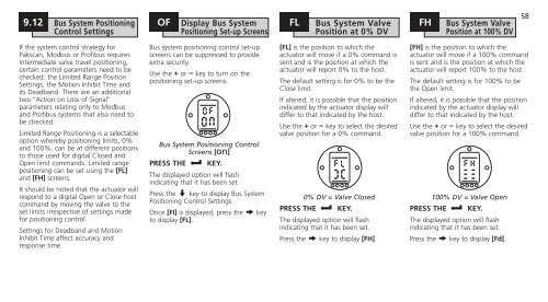
- Page 389 and 390: 9.8 Bus System Option Pakscan [OP]
- Page 391 and 392: PF Pakscan Remote Auxiliary Input 4
- Page 393 and 394: 9.9 Bus System Option Modbus [OP] P
- Page 395 and 396: PF Modbus Remote Auxiliary Input PP
- Page 397 and 398: 9.10 Bus System Option Profibus DP
- Page 399 and 400: PF Profibus Remote Auxiliary Input
- Page 401 and 402: 9.11 Option DeviceNet PA DeviceNet
- Page 403: PF DeviceNet Remote Auxiliary Input
- Page 407 and 408: JO Position in Valve Opening Stroke
- Page 409 and 410: 9.16 Default Options [d1] and [d2]
- Page 411 and 412: 10 Maintenance, Monitoring and Trou
- Page 413 and 414: 10 Maintenance, Monitoring and Trou
- Page 415 and 416: H3 Factors Inhibiting Electrical Op
- Page 417 and 418: H6 Torque Switch Status & IR Settin
- Page 419 and 420: 10.2 IrDA Diagnostics & Config. IQ
- Page 421 and 422: BHD Binary, Hexadecimal and Decimal
- Page 423 and 424: If your Rotork actuator has been co
- Page 425 and 426: New Zealand Wellington Agent North
- Page 428: Heading ATTENTION: RED PLASTIC PLUG