33 12 16.26 - 001-A - Response AAN-ANR Butterfly Valves - Garney ...
33 12 16.26 - 001-A - Response AAN-ANR Butterfly Valves - Garney ... 33 12 16.26 - 001-A - Response AAN-ANR Butterfly Valves - Garney ...
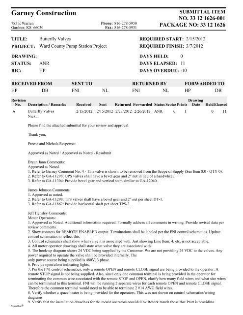
Garney Construction 785 E Warren Gardner, KS 66030 Phone: 816-278-5950 Fax: 816-278-5931 SUBMITTAL ITEM NO. 33 12 1626-001 PACKAGE NO: 33 12 1626 TITLE: PROJECT: Butterfly Valves Ward County Pump Station Project REQUIRED START: REQUIRED FINISH: 2/15/2012 3/7/2012 DRAWING: STATUS: BIC: ANR HP DAYS HELD: 0 DAYS ELAPSED: 11 DAYS OVERDUE: -10 RECEIVED FROM HP DB SENT TO FNI NL RETURNED BY FNI NL FORWARDED TO HP DB Revision No. Description / Remarks Received Sent Drawing Returned Forwarded Status Sepias Prints Date HeldElapsed A Butterfly Valves 2/15/2012 2/15/2012 2/23/2012 2/26/2012 ANR 0 1 0 11 Nick, Please find the attached submittal for your review and approval. Thank you, Freese and Nichols Response: Approved as Noted / Approved as Noted - Resubmit Bryan Jann Comments: Approved as Noted. 1. Refer to Garney Comment No. 4 - This valve is shown to be removed from the Scope of Supply (See Item 8.0 - QTY 0). 2. Refer to GA-11298: OPS valves shall have a bevel gear and 2" nut in lieu of a handwheel. 3. Refer to GA-11304: Provide bevel gear and vertical stem similar to GA-12040. James Johnson Comments: 1. Approved as noted. 2. Refer to GA-11298: TPS valves shall have a bevel gear and 2" nut per sheet DT-1. 3. Refer to GA-11862: Provide horizontal shaft per sheet TPS-2. Expedition ® Jeff Hensley Comments: Motor Operators: 1. Approved as Noted. Additional information required. Formally address all comments in writing. Provide revised data per review comments. 2. Show contacts for REMOTE ENABLED output. Terminations shall be labeled per the FNI control schematics. Update control schematics to reflect this. 3. Control schematics shall show what valve it is associated with. Just showing Line Item: 4, etc. is not acceptable. 4. All motor operator drawings shall state what valve they are associated with. 5. The hook-up diagram shows 24 VDC being supplied by the Customer. We are not providing 24 VDC to the valves. Any power required to operate the valve shall be provided internally. The only power source being supplied is 480V, 3 phase. 6. Provide open/close indicating lights. 7. Per the FNI control schematics, only a remote OPEN and remote CLOSE signal are being provided to the operator. A remote STOP signal is not being supplied. Also, since only one common terminal is being provided in the operator for terminating the common wire associated with the remote STOP and OPEN, clarify how many field wires and what size wires can be terminated to this terminal. FNI will be running 2 separate wires for each remote OPEN and remote CLOSE signal. Therefore the common terminal would need to be able to terminate 2 #14 AWG field wires. 8. Verify whether a space heater is being provided for the operators. This was not shown on control schematics/wiring diagrams. 9. Verify that the installation drawings for the motor operators provided by Rotork match those that Pratt is providing.
- Page 2 and 3: Garney Construction 785 E Warren Ga
- Page 4 and 5: SUBMITTALS https://projectdox.frees
- Page 6 and 7: Colorado River Municipal Water Dist
- Page 8: Colorado River Municipal Water Dist
- Page 11 and 12: Manual Actuator Mounting Positions
- Page 13 and 14: 1513188 HP Page 2 of 5 401 South Hi
- Page 15 and 16: 1513188 HP Page 4 of 5 401 South Hi
- Page 17 and 18: 1513188 HP Page 1 of 4 401 South Hi
- Page 19 and 20: 1513188 HP Page 3 of 5 401 South Hi
- Page 21: Ward County Water Supply Expansion
<strong>Garney</strong> Construction<br />
785 E Warren<br />
Gardner, KS 66030<br />
Phone: 816-278-5950<br />
Fax: 816-278-5931<br />
SUBMITTAL ITEM<br />
NO. <strong>33</strong> <strong>12</strong> 1626-<strong>001</strong><br />
PACKAGE NO: <strong>33</strong> <strong>12</strong> 1626<br />
TITLE:<br />
PROJECT:<br />
<strong>Butterfly</strong> <strong>Valves</strong><br />
Ward County Pump Station Project<br />
REQUIRED START:<br />
REQUIRED FINISH:<br />
2/15/20<strong>12</strong><br />
3/7/20<strong>12</strong><br />
DRAWING:<br />
STATUS:<br />
BIC:<br />
<strong>ANR</strong><br />
HP<br />
DAYS HELD: 0<br />
DAYS ELAPSED: 11<br />
DAYS OVERDUE: -10<br />
RECEIVED FROM<br />
HP<br />
DB<br />
SENT TO<br />
FNI<br />
NL<br />
RETURNED BY<br />
FNI NL<br />
FORWARDED TO<br />
HP<br />
DB<br />
Revision<br />
No.<br />
Description / Remarks<br />
Received<br />
Sent<br />
Drawing<br />
Returned Forwarded Status Sepias Prints Date HeldElapsed<br />
A <strong>Butterfly</strong> <strong>Valves</strong> 2/15/20<strong>12</strong> 2/15/20<strong>12</strong> 2/23/20<strong>12</strong> 2/26/20<strong>12</strong> <strong>ANR</strong> 0 1 0 11<br />
Nick,<br />
Please find the attached submittal for your review and approval.<br />
Thank you,<br />
Freese and Nichols <strong>Response</strong>:<br />
Approved as Noted / Approved as Noted - Resubmit<br />
Bryan Jann Comments:<br />
Approved as Noted.<br />
1. Refer to <strong>Garney</strong> Comment No. 4 - This valve is shown to be removed from the Scope of Supply (See Item 8.0 - QTY 0).<br />
2. Refer to GA-1<strong>12</strong>98: OPS valves shall have a bevel gear and 2" nut in lieu of a handwheel.<br />
3. Refer to GA-11304: Provide bevel gear and vertical stem similar to GA-<strong>12</strong>040.<br />
James Johnson Comments:<br />
1. Approved as noted.<br />
2. Refer to GA-1<strong>12</strong>98: TPS valves shall have a bevel gear and 2" nut per sheet DT-1.<br />
3. Refer to GA-11862: Provide horizontal shaft per sheet TPS-2.<br />
Expedition ®<br />
Jeff Hensley Comments:<br />
Motor Operators:<br />
1. Approved as Noted. Additional information required. Formally address all comments in writing. Provide revised data per<br />
review comments.<br />
2. Show contacts for REMOTE ENABLED output. Terminations shall be labeled per the FNI control schematics. Update<br />
control schematics to reflect this.<br />
3. Control schematics shall show what valve it is associated with. Just showing Line Item: 4, etc. is not acceptable.<br />
4. All motor operator drawings shall state what valve they are associated with.<br />
5. The hook-up diagram shows 24 VDC being supplied by the Customer. We are not providing 24 VDC to the valves. Any<br />
power required to operate the valve shall be provided internally. The<br />
only power source being supplied is 480V, 3 phase.<br />
6. Provide open/close indicating lights.<br />
7. Per the FNI control schematics, only a remote OPEN and remote CLOSE signal are being provided to the operator. A<br />
remote STOP signal is not being supplied. Also, since only one common terminal is being provided in the operator for<br />
terminating the common wire associated with the remote STOP and OPEN, clarify how many field wires and what size wires<br />
can be terminated to this terminal. FNI will be running 2 separate wires for each remote OPEN and remote CLOSE signal.<br />
Therefore the common terminal would need to be able to terminate 2 #14 AWG field wires.<br />
8. Verify whether a space heater is being provided for the operators. This was not shown on control schematics/wiring<br />
diagrams.<br />
9. Verify that the installation drawings for the motor operators provided by Rotork match those that Pratt is providing.
<strong>Garney</strong> Construction<br />
785 E Warren<br />
Gardner, KS 66030<br />
Phone: 816-278-5950<br />
Fax: 816-278-5931<br />
SUBMITTAL ITEM<br />
NO. <strong>33</strong> <strong>12</strong> 1626-<strong>001</strong><br />
PACKAGE NO: <strong>33</strong> <strong>12</strong> 1626<br />
TITLE:<br />
PROJECT:<br />
<strong>Butterfly</strong> <strong>Valves</strong><br />
Ward County Pump Station Project<br />
REQUIRED START:<br />
REQUIRED FINISH:<br />
2/15/20<strong>12</strong><br />
3/7/20<strong>12</strong><br />
DRAWING:<br />
STATUS:<br />
BIC:<br />
<strong>ANR</strong><br />
HP<br />
DAYS HELD: 0<br />
DAYS ELAPSED: 11<br />
DAYS OVERDUE: -10<br />
RECEIVED FROM<br />
HP<br />
DB<br />
SENT TO<br />
FNI<br />
NL<br />
RETURNED BY<br />
FNI NL<br />
FORWARDED TO<br />
HP<br />
DB<br />
Revision<br />
No.<br />
Drawing<br />
Description 9. Verify that / the Remarks installation drawings Receivedfor the Sent motor operators Returned provided Forwarded by Rotork Status match Sepias those Prints that Pratt Date is providing. HeldElapsed<br />
Rebecca Sandoval Comments:<br />
The following comments refer to the Motor Operators and the Limit Switches for TPS-YP5-BFV1.<br />
Refer to Jeff Hensley for comments.<br />
Approved as Noted.<br />
<strong>Garney</strong> Construction<br />
Ward County Pump Station Project<br />
Submittal No. <strong>33</strong> <strong>12</strong> 1626-<strong>001</strong><br />
This submittal has been reviewed and approved with respect to<br />
the contract documents and specification section<strong>33</strong> <strong>12</strong> 1626<br />
Approval or acceptance of the submittal does not relieve the<br />
vendor of their responsibility to comply with the contract<br />
documents.<br />
Supplier/Sub:<br />
HP<br />
Date: ______________ Reviewed by: _________________<br />
®<br />
Expedition Page 2 of 2
SUBMITTALS<br />
https://projectdox.freese.com/imarkupwg/form.asp?formid=6390&wfdirect=&debug=&co...<br />
Page 1 of 2<br />
2/26/20<strong>12</strong><br />
Project No:<br />
Project:<br />
Client:<br />
Contractor:<br />
CMD1<strong>12</strong>69C<br />
CMAR Ward County Transmission System - <strong>Valves</strong><br />
Colorado River Municipal Water District<br />
<strong>Garney</strong><br />
Shop Drawing #004<br />
URGENT <strong>Butterfly</strong> <strong>Valves</strong><br />
WORKFLOW COMPLETED 2/23/20<strong>12</strong> 9:43 AM<br />
SUBMITTAL INFORMATION<br />
SUBMITTAL<br />
TYPE:<br />
SUBMITTAL #: CONTRACTOR REF #: SPEC SECTION: PLAN SHEET: SUBMITTAL STATUS:<br />
Shop<br />
Drawing 004<br />
<strong>33</strong> <strong>12</strong> <strong>16.26</strong> -<br />
<strong>001</strong>-A<br />
<strong>33</strong> <strong>12</strong> <strong>16.26</strong><br />
Approved As Noted, Revise<br />
and Resubmit, Additional<br />
Information Required<br />
SUBMITTAL<br />
DESCRIPTION:<br />
URGENT <strong>Butterfly</strong> <strong>Valves</strong><br />
UPLOAD SUPPORTING DOCUMENTS<br />
<strong>33</strong> <strong>12</strong> <strong>16.26</strong> - <strong>001</strong>-A - <strong>Butterfly</strong> <strong>Valves</strong> .pdf 2/16/20<strong>12</strong> <strong>12</strong>:01 PM Debby Greer<br />
CONTRACTOR CERTIFICATION<br />
CONTRACTOR COMMENTS:<br />
Debby,<br />
Please find the attached submittal for your review and approval.<br />
Thank you,<br />
HOW WILL THE COPIES BE SUBMITTED:<br />
Electronic<br />
NUMBER OF COPIES SUBMITTED: 1<br />
This shop drawing has been reviewed by the Contractor and certified to be in strict conformance with the Contract Documents as modified by addenda, field orders, and<br />
change orders. Deviations can only be approved by field order or change order. Approval is only for conformance with the design concept of the project and compliance<br />
with the intent of the information given in the Contract Documents. Contractor is responsible for dimensions to be confirmed and correlated at the job site; for information<br />
that pertains solely to the fabrication processes or to techniques of construction; and for the work of all trades.<br />
SUBMITTED BY: Jeff Cohen<br />
DATE: 2/16/20<strong>12</strong> 11:10 AM<br />
REVIEWER COMMENTS<br />
REVIEWER NAME: REVIEWER EMAIL: COMPANY / ORGANIZATION DATE SENT: DATE<br />
COMPLETED:<br />
Bryan Jann<br />
bcj@freese.com<br />
Freese & Nichols, Inc.<br />
2/16/20<strong>12</strong><br />
2/23/20<strong>12</strong><br />
REVIEWER<br />
COMMENTS:<br />
Approved as Noted.<br />
1. Refer to <strong>Garney</strong> Comment No. 4 - This valve is shown to be removed from the Scope of<br />
Supply (See Item 8.0 - QTY 0).<br />
2. Refer to GA-1<strong>12</strong>98: OPS valves shall have a bevel gear and 2" nut in lieu of a handwheel.<br />
3. Refer to GA-11304: Provide bevel gear and vertical stem similar to GA-<strong>12</strong>040.<br />
REVIEWER NAME: REVIEWER EMAIL: COMPANY / ORGANIZATION DATE SENT: DATE<br />
COMPLETED:<br />
James<br />
Johnson<br />
jkj@freese.com<br />
Freese and Nichols Inc. 2/16/20<strong>12</strong><br />
2/16/20<strong>12</strong><br />
REVIEWER<br />
COMMENTS:<br />
1. Approved as noted.<br />
2. Refer to GA-1<strong>12</strong>98: TPS valves shall have a bevel gear and 2" nut per sheet DT-1<br />
3. Refer to GA-11862: Provide horizontal shaft per sheet TPS-2<br />
REVIEWER NAME: REVIEWER EMAIL: COMPANY / ORGANIZATION DATE SENT: DATE<br />
COMPLETED:<br />
Jeff Hensley<br />
jnh@freese.com<br />
4055 International Plaza<br />
2/21/20<strong>12</strong><br />
2/22/20<strong>12</strong>
SUBMITTALS<br />
https://projectdox.freese.com/imarkupwg/form.asp?formid=6390&wfdirect=&debug=&co...<br />
Page 2 of 2<br />
2/26/20<strong>12</strong><br />
REVIEWER<br />
COMMENTS:<br />
Motor Operators:<br />
1. Approved as Noted. Additional information required. Formally address all comments in<br />
writing. Provide revised data per review comments.<br />
2. Show contacts for REMOTE ENABLED output. Terminations shall be labeled per the FNI<br />
control schematics. Update control schematics to reflect this.<br />
3. Control schematics shall show what valve it is associated with. Just showing Line Item: 4,<br />
etc. is not acceptable.<br />
4. All motor operator drawings shall state what valve they are associated with.<br />
5. The hook-up diagram shows 24 VDC being supplied by the Customer. We are not providing<br />
24 VDC to the valves. Any power required to operate the valve shall be provided internally. The<br />
only power source being supplied is 480V, 3 phase.<br />
6. Provide open/close indicating lights.<br />
7. Per the FNI control schematics, only a remote OPEN and remote CLOSE signal are being<br />
provided to the operator. A remote STOP signal is not being supplied. Also, since only one<br />
common terminal is being provided in the operator for terminating the common wire<br />
associated with the remote STOP and OPEN, clarify how many field wires and what size wires<br />
can be terminated to this terminal. FNI will be running 2 separate wires for each remote OPEN<br />
and remote CLOSE signal. Therefore the common terminal would need to be able to terminate 2<br />
#14 AWG field wires.<br />
8. Verify whether a space heater is being provided for the operators. This was not shown on<br />
control schematics/wiring diagrams.<br />
9. Verify that the installation drawings for the motor operators provided by Rotork match those<br />
that Pratt is providing.<br />
REVIEWER NAME: REVIEWER EMAIL: COMPANY / ORGANIZATION DATE SENT: DATE<br />
COMPLETED:<br />
Rebecca<br />
Sandoval<br />
rs@freese.com<br />
Freese and Nichols, Inc<br />
2/21/20<strong>12</strong><br />
2/22/20<strong>12</strong><br />
REVIEWER<br />
COMMENTS:<br />
2/22/<strong>12</strong><br />
The following comments refer to the Motor Operators and the Limit Switches for TPS-YP5-<br />
BFV1.<br />
Refer to Jeff Hensley for comments.<br />
Approved as Noted.<br />
UPLOAD SUPPORTING REVIEW DOCUMENTS<br />
DISPLAY ROUTING SLIP<br />
Current Workflow Step: DCS Admin: Debby Greer Workflow Initiator: Jeff Cohen<br />
(Click on the Names above to Email User)<br />
FNI Forms v1.04
<strong>Garney</strong> Construction<br />
785 E Warren<br />
Gardner, KS 66030<br />
Phone: 816-278-5950<br />
Fax: 816-278-5931<br />
SUBMITTAL ITEM<br />
NO. <strong>33</strong> <strong>12</strong> 1626-<strong>001</strong><br />
PACKAGE NO: <strong>33</strong> <strong>12</strong> 1626<br />
TITLE:<br />
PROJECT:<br />
<strong>Butterfly</strong> <strong>Valves</strong><br />
Ward County Pump Station Project<br />
REQUIRED START:<br />
REQUIRED FINISH:<br />
2/15/20<strong>12</strong><br />
3/7/20<strong>12</strong><br />
DRAWING:<br />
STATUS:<br />
BIC:<br />
NEW<br />
FNI<br />
DAYS HELD: 0<br />
DAYS ELAPSED: 0<br />
DAYS OVERDUE: -21<br />
RECEIVED FROM<br />
HP<br />
DB<br />
SENT TO<br />
FNI<br />
NL<br />
RETURNED BY<br />
FNI NL<br />
FORWARDED TO<br />
HP<br />
DB<br />
Revision<br />
No.<br />
Description / Remarks<br />
Received<br />
Sent<br />
Drawing<br />
Returned Forwarded Status Sepias Prints Date HeldElapsed<br />
A <strong>Butterfly</strong> <strong>Valves</strong> 2/15/20<strong>12</strong> 2/15/20<strong>12</strong> NEW 0 1 0 0<br />
Nick,<br />
Please find the attached submittal for your review and approval.<br />
Thank you,<br />
<strong>Garney</strong> Construction<br />
Ward County Pump Station Project<br />
Submittal No. <strong>33</strong> <strong>12</strong> 1626-<strong>001</strong><br />
This submittal has been reviewed and approved with respect to<br />
the contract documents and specification section<strong>33</strong> <strong>12</strong> 1626<br />
Approval or acceptance of the submittal does not relieve the<br />
vendor of their responsibility to comply with the contract<br />
documents.<br />
Supplier/Sub:<br />
HP<br />
Date: ______________ Reviewed by: _________________<br />
Expedition ®
Colorado River Municipal Water District<br />
Ward County Water Supply Expansion Project<br />
Submittal <strong>33</strong> <strong>12</strong> <strong>16.26</strong> – <strong>001</strong>-A – <strong>Butterfly</strong> <strong>Valves</strong><br />
Table of Contents<br />
Page 1<br />
Page 2<br />
Page 4<br />
Page 5<br />
Page 6<br />
Page 8<br />
Page 8<br />
Page 13<br />
Page 17<br />
Page 18<br />
Page 24<br />
Page 38<br />
Page 39<br />
Page 39<br />
Page 49<br />
Page 53<br />
Page 58<br />
Page 61<br />
Page 61<br />
Page 68<br />
Page 70<br />
Page 82<br />
Page 84<br />
Page 98<br />
Page 100<br />
Page 107<br />
Page 109<br />
Page 113<br />
Page <strong>12</strong>5<br />
Page 139<br />
Page 152<br />
Page 165<br />
<strong>Garney</strong> Cover Letter<br />
<strong>Garney</strong> Table of Contents<br />
<strong>Garney</strong> Review Comments<br />
Manufacturer’s Cover Letter<br />
Manufacturer’s Table of Contents<br />
TAB 1 – General Information<br />
Scope of Supply<br />
Estimated Ship Date Schedule<br />
Valve Weights<br />
Valve Torque Calculations<br />
Electric Motor Torque Calculations<br />
Submittal Detail Highlights<br />
TAB 2 – Drawings<br />
Valve Dimensional Drawings<br />
Valve Cross Section Drawings<br />
Manual Actuator Drawings<br />
Valve Accessory Drawings<br />
TAB 3 – <strong>Valves</strong><br />
AWWA 2FII BFV 3” to 20” Brochure<br />
AWWA 2FII BFV 3” to 20” Spec Sheet<br />
AWWA BFV Segmented Seat Brochure<br />
AWWA BFW Segmented Seat Spec Sheet<br />
Triton XR-70 BFV Brochure<br />
Triton XR-70 BFV Spec Sheet<br />
HP 250 II BFV Brochure<br />
HP 250 II & 350 BFV Spec Sheet<br />
HP 350 BFV Brochure<br />
AWWA 2FII BFV 3” to 20” O&M<br />
Triton XR-70 BFV O&M<br />
HP 250 II BFV O&M<br />
HP 350 BFV O&M<br />
Diviner Position Indicator O&M
Page 173<br />
Page 174<br />
Page 179<br />
Page 179<br />
Page 189<br />
Page 203<br />
Page 204<br />
Page 207<br />
Page 209<br />
Page 210<br />
Page 211<br />
Page 2<strong>12</strong><br />
Page 213<br />
Page 214<br />
Page 244<br />
Page 268<br />
Page 300<br />
Page 300<br />
Page 307<br />
Page 311<br />
Page 318<br />
Page 319<br />
Page <strong>33</strong>9<br />
Page 425<br />
BFV Extended Storage and Installation Information<br />
BFV Liquid Epoxy Coating<br />
TAB 4 – Manual Actuators and Gearboxes<br />
MDT Manual Actuator Brochure<br />
MDT Manual Actuator O&M<br />
MDT Actuator Mounting Positions Chart<br />
AUMA Actuator Data Sheets<br />
AUMA Actuator Dimensional Drawings<br />
AUMA Actuator Output Mounting Flange Dimensions<br />
AUMA Actuator Mounting Positions Chart<br />
AUMA Limit Switch Position Indicator Drawing<br />
AUMA Limit Switch Position Indicator Wiring Diagram<br />
AUMA Limit Switch Position Indicator Specification<br />
AUMA Actuator Gearbox Catalog Valve Position Indicator<br />
AUMA Multi-Turn Bevel Gear Catalog<br />
AUMA Part-Turn Gearboxes Catalog<br />
TAB 5 – Electric Actuators & Accessories<br />
Rotork Actuator Data Sheets<br />
Rotork Actuator Wiring Diagrams<br />
Rotork Actuator Installation / Dimensional Drawings<br />
Rotork Actuator Mounting Positions Chart<br />
Rotork IQ and IQT Range Brochure<br />
Rotork IQ Range Installation, Operation and Maintenance<br />
Instructions<br />
Rotork IQ Range Basic Instructions
Colorado River Municipal Water District<br />
Ward County Water Supply Expansion Project<br />
Submittal <strong>33</strong> <strong>12</strong> <strong>16.26</strong> – <strong>001</strong>-A – <strong>Butterfly</strong> <strong>Valves</strong><br />
<strong>Garney</strong> Review Comments<br />
1. This submittal includes information on the <strong>Butterfly</strong> <strong>Valves</strong>, Gearboxes, and<br />
Actuators.<br />
2. All of the valves in this submittal will be provided with a mechanically fastened,<br />
segmented seat with the exception of OPS-PL-BFV1, OPS-PL-BFV2, OPS-PL-<br />
BFV3, OPS-PL-BFV4, and OPS-PL-BFV5.<br />
3. The following valves will be shipped prepped for long term storage; OPS-YP1-<br />
BFV, OPS-P1-BFV2, OPS-P2-BFV2, TPS-P1-BFV2, TPS-P2-BFV2, TPS-P3-<br />
BFV2, TPS-P4-BFV2, WPS-P1-BFV1, WPS-P2-BFV1, WPS-P3-BFV1, TP-<br />
BFV2, TP-BFV3, and TP-BFV4.<br />
4. OPS-YP1-BFV will be provided as a spare part to the owner.<br />
5. Per the discussion at the Pre-Submittal Meeting 4 Rotork Remote Setting Tools<br />
will be provided to the owner with these valves.<br />
6. A table showing number of turns for each of the different sizes of valves will be<br />
included in the operation and maintenance manual.<br />
7. Henry Pratt has over 10 years of successful experience manufacturing this type of<br />
valve in the sizes included in this submittal.<br />
8. Testing and conformance documentation will be provided prior to valve shipment<br />
and will be included in the Operation & Maintenance manual for these valves.<br />
9. The O&M Manual for the Segmented Seat <strong>Valves</strong> will be included in the O&M<br />
Manual.<br />
10. Concerning the limit switches for the 48” <strong>Butterfly</strong> Valve. Henry Pratt has had<br />
discussions with Auma concerning this issue and are proposing the switches as<br />
shown in the catalog beginning on page 214 of this manual. Auma has had a lot<br />
of success with this arrangement and they do not offer individual lever type limit<br />
Switches as discussed during the pre-submittal meeting. As these gear<br />
assemblies require the bevel etc. Pratt cannot modify the wormgear to add Limit<br />
Switches as this would void Auma’s product warranty. Having the self contained<br />
arrangement. This arrangement does offer some substantial benefits, see pages<br />
234 and 235 of this submittal, enclosure type ( IP 68) and lubricated for life.
Ward County Water Supply Expansion Project Transmission,<br />
Odessa and Well Field Pump Stations<br />
<strong>Butterfly</strong> <strong>Valves</strong><br />
Cover Letter<br />
Table of Contents<br />
Tab 1 - General Information<br />
Scope of Supply<br />
Estimated Ship Date Schedule<br />
Valve Weights<br />
Valve Torque Calculations<br />
Electric Motor Torque Calculations (Rotork)<br />
Submittal Detail Highlights<br />
Tab 2 - Drawings<br />
Valve Dimensional Drawings<br />
Cross Section Drawings<br />
Manual Actuator Drawings<br />
Valve Accessory Drawings<br />
Tab 3 – <strong>Valves</strong><br />
BFV Valve 2F2 Bonded Seat Brochure<br />
BFV Valve 2F2 Bonded Seat Spec Sheet<br />
BFV Segmented Seat Brochure<br />
BFV Segmented Seat Spec Sheet<br />
BFV Valve Triton XR-70 Brochure<br />
BFV Valve Triton XR-70 Spec Sheet<br />
BFV Valve HP250II Brochure<br />
BFV HP250II Spec Sheet<br />
BFV Valve HP350 Brochure<br />
BFV HP350 Spec Sheet<br />
BFV Valve 2F2 Operation and Maintenance Manual<br />
BFV Valve Triton XR-70 Operation and Maintenance Manual<br />
BFV HP250II Operation and Maintenance Manual<br />
BFV HP350 Operation and Maintenance Manual<br />
BFV Extended Storage and Installation Information<br />
BFV Valve Coating<br />
Tab 4 – Manual Actuators<br />
Manual Actuator Brochure<br />
Manual Actuator O&M Manual
Manual Actuator Mounting Positions Chart<br />
Actuator Data Sheets (Auma)<br />
Actuator Dimensional Drawings (Auma)<br />
Actuator Output Drive/Mounting Flange Drawings (Auma)<br />
Actuator Mounting Positions Chart (Auma)<br />
Limit Switch General Arrangement Drawing (Auma)<br />
Limit Switch Wiring Diagram (Auma)<br />
Limit Switch Spec (Auma)<br />
Actuator Gearbox Catalog Valve Position Indicator (Auma)<br />
Actuator Multi-turn Bevel Gears Catalog (Auma)<br />
Actuator Part-turn Gearbox Catalog (Auma)<br />
Tab 5 – Electric Actuators & Accessory<br />
Actuator Data Sheets (Rotork)<br />
Actuator Wiring Diagrams (Rotork)<br />
Actuator Installation/Dimensional Drawings (Rotork)<br />
Actuator Mounting Positions Chart (Rotork)<br />
Rotork IQ & IQT Range<br />
Rotork IQ Range Installation & Maintenance Instructions<br />
Rotork IQ Range Basic Setting Instructions
1513188 HP<br />
Page 1 of 5<br />
401 South Highland Avenue<br />
Aurora IL, 60506-5563<br />
Phone: 630-844-4000<br />
Fax: 630-844-4160<br />
Product Submittal : FEBRUARY 10, 20<strong>12</strong><br />
Customer : GARNEY COMPANIES INC<br />
Customer PO#<br />
Pratt Order #<br />
Project<br />
: LOI<br />
: 1513188 HP<br />
: WARD COUNTY<br />
SCOPE OF SUPPLY<br />
LINE QTY TAG/LOCATION DESCRIPTION<br />
1.0 4 TPS-P1-BFV1,<br />
TPS-P2-BFV1,<br />
TPS-P3-BFV1,<br />
TPS-P4-BFV1<br />
2.0 4 TPS-P1-BFV2,<br />
TPS-P2-BFV2,<br />
TPS-P3-BFV2,<br />
TPS-P4-BFV2<br />
3.0 2 OPS-P1-BFV1,<br />
OPS-P2-BFV1<br />
30 150B FLG BFV SEGMENT<br />
SEAT MDT5 OL S/S<br />
18 350 FL BFV MDT4S HW OL<br />
S/S<br />
36 150B FLG BFV SEGMENT<br />
SEAT MDT5 HW OL S/S<br />
PAINT<br />
INT/EXT/OPER: AMERCOAT<br />
370 EPOXY (A-69636A) (Min. 8<br />
MILS)<br />
INT/EXT/OPER: AMERCOAT<br />
370 EPOXY (A-69636A) (Min. 8<br />
MILS)<br />
INT/EXT/OPER: AMERCOAT<br />
370 EPOXY (A-69636A) (Min. 8<br />
MILS)<br />
DRAWING<br />
GA: GA-1<strong>12</strong>98<br />
C.S.: D71094-1<br />
C.S.: D71094-2<br />
A.C.S.: GA-11566<br />
G.A.: GA-11862<br />
C.S.: GA-11724<br />
A.C.S.: GA-11500<br />
GA: GA-1<strong>12</strong>98<br />
C.S.: D71094-1<br />
C.S.: D71094-2<br />
A.C.S.: GA-11566<br />
4.0 5 OPS-P1-BFV2,<br />
OPS-P2-BFV2,<br />
WPS-P1-BFV1,<br />
WPS-P2-BFV1,<br />
WPS-P3-BFV1<br />
18 150B FL BFV OC EMO HW<br />
OL S/S (ROTORK)<br />
INT/EXT: AMERCOAT 370<br />
EPOXY (A-69636A) (Min. 8<br />
MILS)<br />
EMO: VENDOR PAINT (Min. 4<br />
MILS)<br />
G.A.: GA-10658<br />
C.S.: GA-11486<br />
A.D.S.: 1M017701<br />
W.D.: WD21026<br />
I.D.: 1M017701-02<br />
A.C.S. Actuator Cross Section A.D. Accessory Drawing A.D.D. Actuator Dimensional Drawing<br />
A.D.S. Actuator Data Sheet AD Accessory Drawing C.S. Cross Section<br />
CS Cross Section G.A. General Arrangement GA General Arrangement<br />
I.D. Installation Drawing W.D. Wiring Diagram
1513188 HP<br />
Page 2 of 5<br />
401 South Highland Avenue<br />
Aurora IL, 60506-5563<br />
Phone: 630-844-4000<br />
Fax: 630-844-4160<br />
LINE QTY TAG/LOCATION DESCRIPTION<br />
PAINT<br />
DRAWING<br />
5.0 1 TPS-YP1-BFV1 30 150B FL BFV SEGMENT INT/EXT: AMERCOAT 370 GA: GA-<strong>12</strong>040<br />
SEAT BSN OL S/S EXS (AUMA EPOXY (A-69636A) (Min. 8 C.S.: D71094-1<br />
WORM GEAR)<br />
MILS)<br />
C.S.: D71094-2<br />
XSTEM: NONE<br />
A.D.: GA-11456<br />
WG: VENDOR PAINT (Min. 4<br />
A.D.: GA-11<strong>33</strong>9<br />
MILS)<br />
A.D.S.:<br />
A<strong>12</strong>0170-DS002<br />
A.D.D.: SD1<strong>12</strong>799<br />
A.D.D.: SK099241<br />
6.0 2 TPS-YP2-BFV1,<br />
TPS-YP3-BFV1<br />
48 150B FLG BFV SEGMENT<br />
SEAT BSN OL S/S EXS (AUMA<br />
WORM GEAR)<br />
INT/EXT: AMERCOAT 370<br />
EPOXY (A-69636A) (Min. 8<br />
MILS)<br />
XSTEM: NONE<br />
WG: VENDOR PAINT (Min. 4<br />
MILS)<br />
GA: GA-<strong>12</strong>040<br />
C.S.: D71094-1<br />
C.S.: D71094-2<br />
AD: GA-11456<br />
AD: GA-11<strong>33</strong>9<br />
A.D.S.:<br />
A<strong>12</strong>0170-SD004<br />
A.D.D.: SD1<strong>12</strong>800<br />
A.D.D.: SK099241<br />
7.0 1 TPS-YP5-BFV1 48 350 FLG BFV BSN OL S/S INT/EXT: AMERCOAT 370 GA: GA-<strong>12</strong>225<br />
EXS W/LIMIT SWITCH (AUMA EPOXY (A-69636A) (Min. 8 C.S.: GA-11<strong>33</strong>8<br />
WORK GEAR)<br />
MILS)<br />
AD: GA-11456<br />
XSTEM: NONE<br />
AD: GA-11<strong>33</strong>9<br />
WG: VENDOR PAINT (Min. 4<br />
A.D.S.:<br />
MILS)<br />
A<strong>12</strong>0170-SD004<br />
A.D.D.: SD1<strong>12</strong>800<br />
A.D.D.: SK099241<br />
8.0 0 OPS-YP1-BFV 30 150B FLG BFV SEGMENT INT/EXT: AMERCOAT 370 G.A.: GA-<strong>12</strong>040<br />
SEAT BSN OL S/S EXS (AUMA EPOXY (A-69636A) (Min. 8 CS: D71094-1<br />
WORM GEAR)<br />
MILS)<br />
CS: D71094-2<br />
DUPLICATE OF OPS-PL-BFV6<br />
XSTEM: NONE<br />
AD: GA-11456<br />
WG: VENDOR PAINT (Min. 4<br />
NOW ON LINE<br />
AD: GA-11<strong>33</strong>9<br />
MILS)<br />
A.D.S.:<br />
A<strong>12</strong>0170-DS002<br />
A.D.D.: SD1<strong>12</strong>799<br />
A.D.D.: SK099241<br />
A.C.S. Actuator Cross Section A.D. Accessory Drawing A.D.D. Actuator Dimensional Drawing<br />
A.D.S. Actuator Data Sheet AD Accessory Drawing C.S. Cross Section<br />
CS Cross Section G.A. General Arrangement GA General Arrangement<br />
I.D. Installation Drawing W.D. Wiring Diagram
1513188 HP<br />
Page 3 of 5<br />
401 South Highland Avenue<br />
Aurora IL, 60506-5563<br />
Phone: 630-844-4000<br />
Fax: 630-844-4160<br />
LINE QTY TAG/LOCATION DESCRIPTION<br />
PAINT<br />
DRAWING<br />
9.0 1 OPS-YP2-BFV1 36 150B FLG BFV SEGMENT INT/EXT: AMERCOAT 370 GA: GA-<strong>12</strong>040<br />
SEAT BSN OL S/S EXS (AUMA EPOXY (A-69636A) (Min. 8 C.S.: D71094-1<br />
WORM GEAR)<br />
MILS)<br />
C.S.: D71094-2<br />
XSTEM: NONE<br />
AD: GA-11456<br />
WG: VENDOR PAINT (Min. 4<br />
AD: GA-11<strong>33</strong>9<br />
MILS)<br />
A.D.S.:<br />
A<strong>12</strong>0170-DS003<br />
A.D.D.: SD1<strong>12</strong>799<br />
A.D.D.: SK099241<br />
<strong>12</strong>.0 2 WPS-YP1-BFV1,<br />
WPS-YP1-BFV2<br />
18 150B FL BFV OC EMO HW<br />
OL S/S TFS (ROTORK)<br />
INT/EXT: AMERCOAT 370<br />
EPOXY (A-69636A) (Min. 8<br />
MILS)<br />
TT/FLRSTD: AMERCOAT 370<br />
EPOXY (A-69636A) (Min. 8<br />
MILS)<br />
EMO: VENDOR PAINT (Min. 4<br />
MILS)<br />
G.A.: GA-10660<br />
C.S.: GA-11486<br />
A.D.S.: 1M017702<br />
W.D.: WD21025<br />
W.D.: WS21035<br />
W.D.: WS21034<br />
I.D.: 1M017702-02<br />
13.0 3 WPS-YP1-BFV3,<br />
WPS-YP2-BFV1,<br />
WPS-YP3-BFV1<br />
36 150B FLG BFV SEGMENT<br />
SEAT OC EMO HW OL S/S TFS<br />
(ROTORK)<br />
INT/EXT: AMERCOAT 370<br />
EPOXY (A-69636A) (Min. 8<br />
MILS)<br />
TT/FLRSTD: AMERCOAT 370<br />
EPOXY (A-69636A) (Min. 8<br />
MILS)<br />
EMO: VENDOR PAINT (Min. 4<br />
MILS)<br />
G.A.: GA-10769<br />
C.S.: D71094-1<br />
CS: D71094-2<br />
A.D.S.: 1M017801<br />
W.D.: WD21025<br />
W.D.: WS21035<br />
I.D.: 1M017801-02<br />
14.0 1 WPS-YP4-BFV1 20 150B FL BFV OC EMO HW INT/EXT: AMERCOAT 370 G.A.: GA-10660<br />
OL S/S TFS (ROTORK)<br />
EPOXY (A-69636A) (Min. 8 C.S.: GA-11486<br />
MILS)<br />
A.D.S.: 1M017703<br />
TT/FLRSTD: AMERCOAT 370<br />
W.D.: WD21025<br />
EPOXY (A-69636A) (Min. 8<br />
W.D.: WS21035<br />
MILS)<br />
EMO: VENDOR PAINT (Min. 4 W.D.: WS21034<br />
MILS)<br />
I.D.: 1M017703-02<br />
15.0 1 WPS-YP4-BFV2 36 150B FLG BFV SEGMENT INT/EXT: AMERCOAT 370 GA: GA-10769<br />
SEAT OC EMO HW OL S/S TFS EPOXY (A-69636A) (Min. 8 C.S.: D71094-1<br />
(ROTORK)<br />
MILS)<br />
C.S.: D71094-2<br />
TT/FLRSTD: AMERCOAT 370<br />
A.D.S.: 1M017802<br />
EPOXY (A-69636A) (Min. 8<br />
W.D.: WD21025<br />
MILS)<br />
EMO: VENDOR PAINT (Min. 4 W.D.: WS21035<br />
MILS)<br />
I.D.: 1M017802-02<br />
A.C.S. Actuator Cross Section A.D. Accessory Drawing A.D.D. Actuator Dimensional Drawing<br />
A.D.S. Actuator Data Sheet AD Accessory Drawing C.S. Cross Section<br />
CS Cross Section G.A. General Arrangement GA General Arrangement<br />
I.D. Installation Drawing W.D. Wiring Diagram
1513188 HP<br />
Page 4 of 5<br />
401 South Highland Avenue<br />
Aurora IL, 60506-5563<br />
Phone: 630-844-4000<br />
Fax: 630-844-4160<br />
LINE QTY TAG/LOCATION DESCRIPTION<br />
PAINT<br />
DRAWING<br />
16.0 1 WPS-YP5-BFV1 30 150B FLG BFV SEGMENT INT/EXT: AMERCOAT 370 GA: GA-10769<br />
SEAT OC EMO HW OL S/S TFS EPOXY (A-69636A) (Min. 8 CS: D71094-1<br />
(ROTORK)<br />
MILS)<br />
CS: D71094-2<br />
TT/FLRSTD: AMERCOAT 370<br />
A.D.S.: 1M017804<br />
EPOXY (A-69636A) (Min. 8<br />
W.D.: WD21025<br />
MILS)<br />
EMO: VENDOR PAINT (Min. 4 W.D.: WS21035<br />
MILS)<br />
I.D.: 1M017804-02<br />
17.0 1 WPS-YP5-BFV2 36 150B FLG BFV SEGMENT INT/EXT: AMERCOAT 370 G.A.: GA-10769<br />
SEAT OC EMO HW OL S/S TFS EPOXY (A-69636A) (Min. 8 C.S.: D71094-1<br />
(ROTORK)<br />
MILS)<br />
C.S.: D71094-2<br />
TT/FLRSTD: AMERCOAT 370<br />
A.D.S.: 1M017803<br />
EPOXY (A-69636A) (Min. 8<br />
W.D.: WD21025<br />
MILS)<br />
EMO: VENDOR PAINT (Min. 4 W.D.: WS21035<br />
MILS)<br />
I.D.: 1M017803-02<br />
18.0 3 WPS-YP1-BFV5,<br />
WPS-YP1-BFV6,<br />
OPS-PL-BFV6<br />
30 150B FLG BFV SEGMENT<br />
SEAT BSN OL S/S EXS (AUMA<br />
WORM GEAR)<br />
INT/EXT: AMERCOAT 370<br />
EPOXY (A-69636A) (Min. 8<br />
MILS)<br />
XSTEM: NONE<br />
WG: VENDOR PAINT (Min. 4<br />
MILS)<br />
GA: GA-<strong>12</strong>040<br />
CS: D71094-1<br />
C.S.: D71094-2<br />
AD: GA-11456<br />
AD: GA-11<strong>33</strong>9<br />
A.D.S.:<br />
A<strong>12</strong>0170-DS002<br />
A.D.D.: SD1<strong>12</strong>799<br />
A.D.D.: SK099241<br />
22.0 3 TP-BFV2,<br />
TP-BFV3,<br />
TP-BFV4<br />
48 250B FL BFV WG40-300 BSN<br />
OL S/S<br />
INT/EXT/OPER: AMERCOAT<br />
370 EPOXY (A-69636A) (Min. 8<br />
MILS)<br />
G.A.: GA-11774<br />
C.S.: GA-11<strong>33</strong>8<br />
A.C.S.: GA-11881<br />
23.0 1 OPS-PL-BFV1 30 150B FL BFV MDT5 BSN OL INT/EXT/OPER: AMERCOAT GA: GA-11304<br />
S/S<br />
370 EPOXY (A-69636A) (Min. 8 C.S.: GA-11<strong>33</strong>8<br />
MILS)<br />
A.C.S.: GA-11528<br />
24.0 1 OPS-PL-BFV2 24 150B FL BFV MDT4S BSN INT/EXT/OPER: AMERCOAT G.A.: GA-11304<br />
OL S/S<br />
370 EPOXY (A-69636A) (Min. 8 C.S.: GA-11<strong>33</strong>7<br />
MILS)<br />
A.C.S.: GA-11499<br />
A.C.S. Actuator Cross Section A.D. Accessory Drawing A.D.D. Actuator Dimensional Drawing<br />
A.D.S. Actuator Data Sheet AD Accessory Drawing C.S. Cross Section<br />
CS Cross Section G.A. General Arrangement GA General Arrangement<br />
I.D. Installation Drawing W.D. Wiring Diagram
1513188 HP<br />
Page 5 of 5<br />
401 South Highland Avenue<br />
Aurora IL, 60506-5563<br />
Phone: 630-844-4000<br />
Fax: 630-844-4160<br />
LINE QTY TAG/LOCATION DESCRIPTION<br />
25.0 3 OPS-PL-BFV3,<br />
OPS-PL-BFV4,<br />
OPS-PL-BFV5<br />
30 150B FL BFV MDT5 BSN OL<br />
S/S<br />
PAINT<br />
INT/EXT/OPER: AMERCOAT<br />
370 EPOXY (A-69636A) (Min. 8<br />
MILS)<br />
Included in Submittal:<br />
Customer to verify extension lengths on GA-10769 & GA-10660 - See Detail Highlights form.<br />
BFV Catalog Data (2F2 - Bonded Seat)<br />
BFV Catalog Data (Triton)<br />
BFV Catalog Data (HP250II)<br />
BFV Catalog Data (HP350)<br />
BFV Paint Data (A069636A)<br />
Pratt Valve Torque Calculations<br />
Rotork Electric Motor Torque Calculations<br />
O&M Manual - BFV<br />
DRAWING<br />
GA: GA-11304<br />
C.S.: GA-11<strong>33</strong>8<br />
A.C.S.: GA-11528<br />
Note:<br />
Start Up assistance not provided in this quotation.<br />
EMO and Worm Gear spare parts not included.<br />
Test Certs available at time of shipment.<br />
A.C.S. Actuator Cross Section A.D. Accessory Drawing A.D.D. Actuator Dimensional Drawing<br />
A.D.S. Actuator Data Sheet AD Accessory Drawing C.S. Cross Section<br />
CS Cross Section G.A. General Arrangement GA General Arrangement<br />
I.D. Installation Drawing W.D. Wiring Diagram
1513188 HP<br />
Page 1 of 4<br />
401 South Highland Avenue<br />
Aurora IL, 60506-5563<br />
Phone: 630-844-4000<br />
Fax: 630-844-4160<br />
Product Submittal : FEBRUARY 14, 20<strong>12</strong><br />
Customer : GARNEY COMPANIES INC<br />
Customer PO#<br />
Pratt Order #<br />
Project<br />
: LOI<br />
: 1513188 HP<br />
: WARD COUNTY<br />
SCOPE OF SUPPLY<br />
LINE QTY TAG/LOCATION DESCRIPTION<br />
1.0 4 TPS-P1-BFV1,<br />
TPS-P2-BFV1,<br />
TPS-P3-BFV1,<br />
TPS-P4-BFV1<br />
2.0 4 TPS-P1-BFV2,<br />
TPS-P2-BFV2,<br />
TPS-P3-BFV2,<br />
TPS-P4-BFV2<br />
3.0 2 OPS-P1-BFV1,<br />
OPS-P2-BFV1<br />
30 150B FLG BFV SEGMENT<br />
SEAT MDT5 OL S/S<br />
18 350 FL BFV MDT4S HW OL<br />
S/S<br />
36 150B FLG BFV SEGMENT<br />
SEAT MDT5 HW OL S/S<br />
E S D Release 2/15 E S D Release 2/29<br />
7/20/<strong>12</strong> 7/20/<strong>12</strong><br />
4/6/<strong>12</strong> 4/20/<strong>12</strong><br />
7/20/<strong>12</strong> 7/20/<strong>12</strong><br />
4.0 5 OPS-P1-BFV2,<br />
OPS-P2-BFV2,<br />
WPS-P1-BFV1,<br />
WPS-P2-BFV1,<br />
WPS-P3-BFV1<br />
18 150B FL BFV OC EMO HW<br />
OL S/S (ROTORK)<br />
6/20/<strong>12</strong> 7/<strong>12</strong>/<strong>12</strong>
1513188 HP<br />
Page 2 of 5<br />
401 South Highland Avenue<br />
Aurora IL, 60506-5563<br />
Phone: 630-844-4000<br />
Fax: 630-844-4160<br />
LINE QTY TAG/LOCATION DESCRIPTION<br />
E SD Release 2/15 E S D Release 2/29<br />
5.0 1 TPS-YP1-BFV1 30 150B FL BFV SEGMENT 7/20/<strong>12</strong> 7/20/<strong>12</strong><br />
SEAT BSN OL S/S EXS (AUMA<br />
WORM GEAR)<br />
6.0 2 TPS-YP2-BFV1,<br />
TPS-YP3-BFV1<br />
48 150B FLG BFV SEGMENT<br />
SEAT BSN OL S/S EXS (AUMA<br />
WORM GEAR)<br />
6/29/<strong>12</strong> 7/20/<strong>12</strong><br />
7.0 1 TPS-YP5-BFV1 48 350 FLG BFV BSN OL S/S 6/29/<strong>12</strong> 7/20/<strong>12</strong><br />
EXS W/LIMIT SWITCH (AUMA<br />
WORK GEAR)<br />
8.0 1 OPS-YP1-BFV 7/20/<strong>12</strong> 7/20/<strong>12</strong><br />
30 150B FLG BFV SEGMENT<br />
SEAT BSN OL S/S EXS (AUMA<br />
WORM GEAR)
1513188 HP<br />
Page 3 of 5<br />
401 South Highland Avenue<br />
Aurora IL, 60506-5563<br />
Phone: 630-844-4000<br />
Fax: 630-844-4160<br />
LINE QTY TAG/LOCATION DESCRIPTION<br />
EE S D Release 2/15 ESD Release 2/29<br />
9.0 1 OPS-YP2-BFV1 36 150B FLG BFV SEGMENT 7/20/<strong>12</strong> 7/20/<strong>12</strong><br />
SEAT BSN OL S/S EXS (AUMA<br />
WORM GEAR)<br />
<strong>12</strong>.0 2 WPS-YP1-BFV1,<br />
WPS-YP1-BFV2<br />
18 150B FL BFV OC EMO HW<br />
OL S/S TFS (ROTORK)<br />
6/20/<strong>12</strong> 7/<strong>12</strong>/<strong>12</strong><br />
13.0 3 WPS-YP1-BFV3,<br />
WPS-YP2-BFV1,<br />
WPS-YP3-BFV1<br />
36 150B FLG BFV SEGMENT<br />
SEAT OC EMO HW OL S/S TFS<br />
(ROTORK)<br />
7/27/<strong>12</strong> 7/27/<strong>12</strong><br />
14.0 1 WPS-YP4-BFV1 20 150B FL BFV OC EMO HW 6/20/<strong>12</strong> 7/<strong>12</strong>/<strong>12</strong><br />
OL S/S TFS (ROTORK)<br />
15.0 1 WPS-YP4-BFV2 7/27/<strong>12</strong> 7/27/<strong>12</strong><br />
36 150B FLG BFV SEGMENT<br />
SEAT OC EMO HW OL S/S TFS<br />
(ROTORK)
1513188 HP<br />
Page 4 of 5<br />
401 South Highland Avenue<br />
Aurora IL, 60506-5563<br />
Phone: 630-844-4000<br />
Fax: 630-844-4160<br />
LINE QTY TAG/LOCATION DESCRIPTION<br />
E S D Release 2/15 ESD Release 2/29<br />
16.0 1 WPS-YP5-BFV1 30 150B FLG BFV SEGMENT 7/27/<strong>12</strong> 7/27/<strong>12</strong><br />
SEAT OC EMO HW OL S/S TFS<br />
(ROTORK)<br />
17.0 1 WPS-YP5-BFV2 36 150B FLG BFV SEGMENT 7/27/<strong>12</strong> 7/27/<strong>12</strong><br />
SEAT OC EMO HW OL S/S TFS<br />
(ROTORK)<br />
18.0 4 WPS-YP1-BFV5,<br />
WPS-YP1-BFV6,<br />
OPS-PL-BFV5,<br />
OPS-PL-BFV6<br />
22.0 3 TP-BFV2,<br />
TP-BFV3,<br />
TP-BFV4<br />
30 150B FLG BFV SEGMENT<br />
SEAT BSN OL S/S EXS (AUMA<br />
WORM GEAR)<br />
48 250B FL BFV WG40-300 BSN<br />
OL S/S<br />
7/27/<strong>12</strong> 7/27/<strong>12</strong><br />
5/9/<strong>12</strong> 5/25/<strong>12</strong><br />
23.0 1 OPS-PL-BFV1 30 150B FL BFV MDT5 BSN OL 3/9/<strong>12</strong> 3/23/<strong>12</strong><br />
S/S<br />
24.0 1 OPS-PL-BFV2<br />
24 150B FL BFV MDT4S BSN<br />
OL S/S<br />
3/2/<strong>12</strong> 3/16/<strong>12</strong><br />
25.0 2 OPS-PL-BFV3,<br />
OPS-PL-BFV4<br />
30 150B FL BFV MDT5 BSN OL 3/9/<strong>12</strong> 3/23/<strong>12</strong><br />
S/S
Ward County Water Supply Expansion Project Transmission,<br />
Odessa and Well Field Pump Stations<br />
<strong>Butterfly</strong> Valve Weights<br />
Valve Size and Pressure Class<br />
Weight per unit<br />
18” 2FII 150B 600<br />
18” 2FII 150B w/Rotork EMO 1050<br />
18” 2FII 150B w/Rotork EMO & TT/Flrstnd 1300<br />
18” HP350 1100<br />
20” 2FII 150B w/Rotork EMO & TT/Flrstnd 1150<br />
24” Triton 150B 1050<br />
30” Triton 150B 1900<br />
30” Triton 150B w/Auma WG 2000<br />
30” Triton 150B w/Rotork EMO & TT/Flrstnd 2600<br />
36” Triton 150B 2650<br />
36” Triton 150B w/Auma WG 2700<br />
36” Triton 150B w/Rotork EMO & TT/Flrstnd 2950<br />
48” Triton 150B w/Auma WG 6000<br />
48” HP250II 4900<br />
48” HP350 w/Auma WG 8300
AWWA <strong>Butterfly</strong> <strong>Valves</strong><br />
3" – 20"<br />
Engineering Creative Solutions<br />
for Fluid Systems Since 1901
A Tradition of Excellence<br />
With the development of the first rubber seated butterfly<br />
valve more than 70 years ago, the Henry Pratt Company<br />
became a trusted name in the flow control industry,<br />
setting the standard for product quality and customer<br />
service. Today Pratt provides the following range of<br />
superior products to the water, wastewater and power<br />
generation industries.<br />
<strong>Butterfly</strong> <strong>Valves</strong>: from 3" to 162"<br />
Rectangular <strong>Valves</strong>: 1' x 1' to 14' x 16'<br />
Ball <strong>Valves</strong> —<br />
Rubber Seated: from 4" to 60"<br />
Metal Seated: from 6" to 48"<br />
Plug <strong>Valves</strong>: from 1/2" to 36", 3 ways<br />
Hydraulic Control Systems<br />
Valve Controls<br />
Energy Dissipating <strong>Valves</strong><br />
and Fixed Energy Dissipaters<br />
Cone <strong>Valves</strong><br />
Check <strong>Valves</strong><br />
A Commitment to Meeting<br />
The Customers’ Needs<br />
Henry Pratt valves represent a long-term commitment<br />
to both the customer and to a tradition of product<br />
excellence. This commitment is evident in the number<br />
of innovations we have brought to the industries we<br />
serve. In fact, the Henry Pratt Company was the first to<br />
introduce many of the flow control products in use today,<br />
including the first rubber seated butterfly valve, one of<br />
the first nuclear N-Stamp valves, and the bonded seat<br />
butterfly valve.<br />
Innovative Products<br />
For Unique Applications<br />
Though many of the standard valves we produce are<br />
used in water filtration and distribution applica tions, Pratt<br />
has built a reputation on the ability to develop specialized<br />
products that help customers to meet their individual<br />
operational challenges.<br />
Creative Engineering<br />
for Fluid Systems<br />
Pratt’s ability to provide practical solutions to complex<br />
issues is demonstrated by the following case histories.<br />
Earthquake Proof <strong>Valves</strong><br />
Pratt designed and manufactured hydraulically actuated<br />
valves for a water storage application so that the valves<br />
would automatically operate in the event of earthquakes.<br />
This lead to the development of a valve that will withstand<br />
acceleration forces of up to 6g’s.<br />
Custom Actuation/Isolation <strong>Valves</strong><br />
Pratt designed and manufactured valves that would<br />
isolate a working chamber in the event of a nuclear<br />
emergency during the decommissioning of armed<br />
nuclear warheads. The valves were able to close in<br />
a millisecond using specially designed Pratt electropneumatic<br />
actuators.<br />
<strong>Valves</strong> Designed for<br />
Harsh Environments<br />
Pratt designed and manufactured a 144" diameter<br />
butterfly valve for the emergency cooling system at<br />
a jet engine test facility. The valve was designed to supply<br />
water to help dissipate the tremen dous heat generated by<br />
the engines during testing.<br />
Through experience, commitment and creative engineering, Pratt is uniquely<br />
suited to provide superior products for our customers’ special needs.<br />
For more information, contact our corporate headquarters in Aurora, Illinois.
Scope of Line:<br />
AWWA In-Plant Rubber Seated <strong>Butterfly</strong> <strong>Valves</strong><br />
Model 2FII <strong>Butterfly</strong> Valve<br />
Model 2FII Flanged <strong>Butterfly</strong> Valve<br />
Sizes: 3 through 20 inches<br />
Body Style: Flanged x flanged ends<br />
Other Body Style Options:<br />
n Mechanical joint<br />
n Victaulic<br />
n Flanged & mechanical joint<br />
n Push-on<br />
n Push-on & flanged<br />
Pressure Class:<br />
n Class 150B per AWWA Standard C504<br />
Working Pressure: 150 psig<br />
Flanges:<br />
n Flat faced and drilled in accordance with ANSI B16.1,<br />
Class <strong>12</strong>5 standards.<br />
Rubber Seat: Bonded seat-in-body<br />
Actuation Options:<br />
n Pratt hand lever<br />
n MDT manual actuator with AWWA nut, handwheel or<br />
chainwheel<br />
n Pratt Dura-Cyl hydraulic or pneumatic cylinder<br />
n Pratt Positron electric actuator<br />
Monoflange MKII Wafer <strong>Butterfly</strong> Valve<br />
Sizes: 3 through 20 inches<br />
Body Style: Wafer-type<br />
Pressure Class:<br />
n Class 150B per AWWA Standard C504<br />
Working Pressure: 150 psig<br />
Rubber Seat:<br />
n Bonded seat-in-body extends over inner surface to<br />
form self-gasketing feature<br />
Actuation Options:<br />
n Pratt hand lever<br />
n MDT manual actuator with AWWA nut, handwheel or<br />
chainwheel<br />
n Pratt Dura-Cyl hydraulic or pneumatic cylinder<br />
n Pratt Positron electric actuator<br />
Monoflange MKII <strong>Butterfly</strong> Valve<br />
2 | Henry Pratt Company
Design Details:<br />
Models 2FII and MKII<br />
Self Adjusting Permanent Packing<br />
Chevron type packing increases sealing force<br />
as line pressure increases. The self adjusting<br />
packing bears on turned, ground and polished<br />
stainless steel, minimizing wear and assuring<br />
long life. Packing is accessible for replacement<br />
without dismantling the valve per AWWA<br />
Standard C504.<br />
Lifetime Bearings<br />
Pratt’s chemically inert nylon bearings are<br />
sized to meet or exceed AWWA specification<br />
pressure loads. They are self-lubricating,<br />
require no periodic maintenance and are<br />
designed to outlast the life of the pipeline.<br />
Corrosion Resistant Shafts<br />
The shafts in Pratt’s rubber seated butterfly<br />
valves, 3” through 20”, are constructed of<br />
centerless, ground ASTM A276 type 304 or<br />
type 316 stainless steel bar and thus are not<br />
susceptible to corrosion as are carbon steel or<br />
other similar materials. Shafts are one-piece,<br />
through-shaft construction, sized to meet or<br />
exceed the requirements of AWWA Standard<br />
C504 for Class 150B butterfly valves.<br />
Streamlined Discs<br />
Pratt’s lens-shaped discs are designed to<br />
minimize pressure drop and turbulence. In<br />
the full open position, the disc creates no<br />
more friction loss than a 45° elbow. Discs<br />
are secured to shafts by stainless steel pins<br />
to transmit required torques and withstand<br />
stresses imposed under a variety of operating<br />
conditions.<br />
Body Seat<br />
Our standard seats are constructed of Buna N<br />
rubber and bonded to the valve body in Pratt’s<br />
manufacturing facility using a unique thermal<br />
process. This molding process ensures that<br />
the disc-to-seat interference will not cause<br />
excessive wear or abrasion under normal<br />
operating conditions. On the wafer type MKII<br />
bodies, the rubber seat covers the entire inner<br />
surface plus the outside face of the valve body<br />
to provide a self-gasketing feature. Pratt’s<br />
seat-in-body design minimizes the effects of<br />
corrosive buildup on the inside of the valve<br />
because deposits are swept away by the hard<br />
sealing edge of the disc each time the valve is<br />
exercised.<br />
Heavy Duty Bodies<br />
Both Monoflange MKII and Model 2FII bodies<br />
are heavy duty cast iron. Model 2FII flanges are<br />
fully faced and drilled in accordance with ANSI<br />
B16.1, Class <strong>12</strong>5 standard for cast iron flanges.<br />
Monoflange MKII bodies incorporate an<br />
overlapping seat which also forms a gasket for<br />
the flange face. The actuator mounting trunnion<br />
is machined and drilled for a 4-bolt connection.<br />
Henry Pratt Company | 3
Features and Benefits:<br />
of Pratt Models 2FII and MKII<br />
Feature<br />
Seat-in-body design<br />
Seat molded in recessed body cavity,<br />
protected by metal on 3 sides<br />
Valve withstood proof-of-design testing<br />
of 100,000 cycles — AWWA only<br />
requires<br />
10,000 cycle proof-of-design testing<br />
Through-disc pinning<br />
Symmetrical lens-shaped disc<br />
Nonmetallic bearings<br />
Chevron V-type packing<br />
Benefit<br />
• Reduces seat failure due to corrosive buildup in the valve and<br />
pipeline. No hardware to loosen. No periodic maintenance required.<br />
Rubber protected from flow media to increase seat life.<br />
• Proven reliability over the life of the valve<br />
• Provides a tight disc-to-shaft pin connection, greatly reducing the<br />
possibility of loosening through vibration<br />
• Higher Cv : lower head loss results in energy savings for customer’s<br />
system<br />
• Prevents galvanic corrosion and provides lower coefficient of friction<br />
• Self-adjusting, lasts the life of the valve<br />
Valve<br />
Size<br />
C v<br />
Valve<br />
Size<br />
C v<br />
Valve<br />
Size<br />
3" 323 10" 4458 16" 11413<br />
4" 575 <strong>12</strong>" 6420 18" 14444<br />
6" <strong>12</strong>94 14" 8738 20" 17832<br />
8" 2300 C v values for the 2FII and MKII in the full open position<br />
C v<br />
Standard<br />
Material<br />
Body<br />
Type of Material<br />
Disc<br />
0255 Cast Iron Cast Iron<br />
316 edge<br />
0132 Ductile Iron SS 316<br />
(MKII 3" – 6")<br />
0274 Ductile Iron<br />
(MKII 8" +)<br />
Cast Iron<br />
316 edge<br />
Shaft<br />
SS,<br />
Type 304<br />
SS,<br />
Type 316<br />
SS,<br />
Type 304<br />
Specifications for<br />
Materials of Construction<br />
Cast Iron:<br />
ASTM A<strong>12</strong>6, Class B (2FII Body)<br />
Ductile Iron:<br />
ASTM A536 (65-45-<strong>12</strong>) (MKII Body)<br />
4 | Henry Pratt Company
Suggested Specification for the Pratt<br />
Rubber Seated <strong>Butterfly</strong> Valve, Sizes 3 through 20 inches<br />
General<br />
<strong>Butterfly</strong> valves shall be manufactured in accordance<br />
with the latest revision of AWWA C504, Class 150B and<br />
conform to NSF Standard 61. The manufacturer shall<br />
have produced AWWA butterfly valves for a minimum of<br />
five years. All valves shall be either Henry Pratt Model 2FII<br />
or Monoflange MKII and comply with the following details.<br />
Valve Bodies<br />
Valve bodies shall be constructed of ASTM A<strong>12</strong>6, Class B<br />
cast iron for flanged valves or ASTM A536 (65-45-<strong>12</strong>) for<br />
wafer style. Flanged valves shall be fully faced and drilled<br />
in accordance with ANSI Standard B16.1, Class <strong>12</strong>5.<br />
Valve Seats<br />
Rubber body seats shall be of one piece construction,<br />
simultaneously molded and bonded into a recessed cavity<br />
in the valve body. Seats may not be located on the disc or<br />
be retained by segments and/or screws. For wafer style<br />
valves, the seat shall cover the entire inner surface of the<br />
valve body and extend over the outside face of the valve<br />
body to form a flange gasket.<br />
Valve Bearings<br />
Valve bearings shall be of a self-lubricating, nonmetallic<br />
material to effectively isolate the disc-shaft assembly from<br />
the valve body. Metal-to-metal thrust bearings in the flow<br />
stream are not allowed.<br />
Valve Disc<br />
The disc shall be a lens-shaped design to afford<br />
minimal pressure drop and line turbulence. Materials of<br />
construction shall be:<br />
• 3"-6" — ASTM A351 Gr. CF8M stainless steel disc<br />
• 8"-20" — ASTM A<strong>12</strong>6, Class B cast iron disc with a<br />
stainless steel type 316 edge<br />
Painting<br />
All surfaces of the valve interior shall be clean, dry and<br />
free from grease before painting. The valve interior and<br />
exterior, except for disc edge, rubber seat and finished<br />
portions shall be evenly coated with an NSF61 approved<br />
2-part liquid epoxy. Minimum dry film thickness shall be<br />
4-6 Mils.<br />
Testing<br />
Hydrostatic and seat leakage tests shall be conducted in<br />
strict accordance with AWWA Standard C504.<br />
Proof of Design<br />
The manufacturer furnishing valves under the<br />
specification shall be prepared to provide Proof of Design<br />
Test reports to illustrate that the valves supplied meet the<br />
design requirements of AWWA C504.<br />
Manual Actuators: Manual actuators shall be of the<br />
traveling nut, self-locking type and shall be designed<br />
to hold the valve in any intermediate position between<br />
fully open and fully closed without creeping or fluttering.<br />
Actuators shall be equipped with mechanical stop-limiting<br />
devices to prevent overtravel of the disc in the open<br />
and closed positions. Actuators shall be fully enclosed<br />
and designed to produce the specified torque with a<br />
maximum pull of 80 lb. on the handwheel or chainwheel.<br />
Actuator components shall withstand an input torque of<br />
450 Lb. Ft. at extreme operator position without damage.<br />
Manual actuators shall conform to AWWA C504 and shall<br />
be Pratt MDT or an approved equal.<br />
Powered Actuators: Refer to Pratt’s <strong>Butterfly</strong> Valve<br />
Actuator brochure for suggested specifications and<br />
detailed information regarding cylinder actuators and<br />
electric actuators.<br />
Discs shall be retained by stainless steel pins which<br />
should extend through the full diameter of the shaft to<br />
withstand the specified line pressure up to valve rating<br />
and the torque required to operate the valve. Disc stops<br />
located in the flow stream are not allowed.<br />
Valve Shafts<br />
Valve shafts shall be of stainless steel type 304. At the<br />
operator end of the valve shaft, a packing gland utilizing<br />
“V” type chevron packing shall be utilized. “O” ring and/or<br />
“U” cup packing is not allowed.<br />
Henry Pratt Company | 5
Dimensional Data:<br />
Model 2FII, Flanged <strong>Butterfly</strong> Valve<br />
E<br />
Nominal Valve<br />
Size A B C D E F G<br />
3 43⁄4 31⁄4 71⁄2 5 3⁄4 4 – 5⁄8 6<br />
4 51⁄2 31⁄2 9 5 15 ⁄16 8 – 5⁄8 71⁄2<br />
6 61⁄2 51⁄8 11 5 1 8 – 3⁄4 91⁄2<br />
8 73⁄4 61⁄2 131⁄2 6 11⁄8 8 – 3⁄4 113⁄4<br />
10 9 97⁄8 16 8 1 3 ⁄16 <strong>12</strong> – 7⁄8 141⁄4<br />
<strong>12</strong> 101⁄2 113⁄8 19 8 11⁄4 <strong>12</strong> – 7⁄8 17<br />
14 117⁄8 <strong>12</strong>3⁄4 21 8 13⁄8 <strong>12</strong> – 1 183⁄4<br />
16 131⁄2 143⁄8 231⁄2 8 1 7 ⁄16 16 – 1 211⁄4<br />
18 143⁄8 151⁄4 25 8 1 9 ⁄16 16 – 11⁄8 223⁄4<br />
20 16 167⁄8 271⁄2 8 11 1 ⁄16 20 – 11⁄8 25<br />
All dimensions shown in inches.<br />
D<br />
— Available in sizes<br />
3 through 20 inches<br />
E<br />
Dimensional Data:<br />
Monoflange MKII Wafer <strong>Butterfly</strong> Valve<br />
Nominal Valve<br />
Size A B C D<br />
3 43⁄4 31⁄4 51⁄4 2 1 ⁄16<br />
4 51⁄2 31⁄2 63⁄4 2 5 ⁄16<br />
6 61⁄2 51⁄8 85⁄8 2 15 ⁄16<br />
8 73⁄4 61⁄2 107⁄8 3 1 ⁄16<br />
10 9 97⁄8 131⁄4 3 3 ⁄16<br />
<strong>12</strong> 101⁄2 11 5 ⁄16 16 3 7 ⁄16<br />
14 117⁄8 <strong>12</strong>3⁄4 175⁄8 3 11 ⁄16<br />
16 131⁄2 143⁄8 201⁄8 4 3 ⁄16<br />
18 143⁄8 151⁄4 211⁄2 4 11 ⁄16<br />
20 16 16 13 ⁄16 2<strong>33</strong>⁄4 5 3 ⁄16<br />
All dimensions shown in inches.<br />
1/16"<br />
1/16"<br />
D<br />
VALVE<br />
SIZE<br />
(in.)<br />
DISC<br />
O.D.<br />
(in.)<br />
MINIMUM<br />
MATING PIPE I.D.<br />
(in.)*<br />
3 3.089 2.41<br />
4 4.074 3.44<br />
6 6.070 5.38<br />
8 8.078 7.53<br />
10 10.098 9.62<br />
<strong>12</strong> <strong>12</strong>.108 11.64<br />
14 13.<strong>33</strong>9 <strong>12</strong>.86<br />
16 15.<strong>33</strong>6 14.79<br />
18 17.370 16.75<br />
20 19.380 18.71<br />
6 | Henry Pratt Company
401 S. Highland Avenue<br />
Aurora, Illinois 60506<br />
P 630-844-4000 F 630-844-4160<br />
www.henrypratt.com<br />
Pratt Rubber Seated <strong>Butterfly</strong> Valve Specs, Sizes 3”-20”<br />
Tag Number(s): OPS-P1-BFV2, OPS-P3-BFV2, WPS-P1-BFV1, WPS-P2-BFV1, WPS-P3-<br />
BFV1, WPS-YP1-BFV1, WPS-YP1-BFV2, WPS-YP4-BFV1<br />
General<br />
<strong>Butterfly</strong> valves are manufactured in accordance with the latest revision of AWWA C504, Class 150B<br />
and conform to NSF Standard 61.<br />
Valve Body<br />
Valve bodies are constructed of ASTM A<strong>12</strong>6, Class B cast iron for flanged valves. Flanged valves<br />
are fully faced and drilled in accordance with ANSI Standard B16.1, Class <strong>12</strong>5.<br />
Valve Seats<br />
Rubber body seats are of one piece construction, simultaneously molded and bonded into a<br />
recessed cavity in the valve body. Seat material is Buna-N.<br />
Valve Bearings<br />
Valve bearings are of a self-lubricating, nonmetallic material to effectively isolate the disc-shaft<br />
assembly from the valve body.<br />
Valve Disc<br />
The disc is lens-shaped design to afford minimal pressure drop and line turbulence.<br />
Materials of construction is:<br />
• 8"-20" — ASTM A<strong>12</strong>6, Class B cast iron disc with a stainless steel type 316 edge<br />
Discs are retained by stainless steel pins which extend through the full diameter of the shaft to<br />
withstand the specified line pressure up to valve rating and the torque required to operate the valve.<br />
Valve Shafts<br />
Valve shafts are made of stainless steel type 304. At the operator end of the valve shaft, a packing<br />
gland of “V” type chevron packing is utilized.<br />
Painting<br />
All surfaces of the valve interior shall be clean, dry and free from grease before painting. The valve<br />
interior and exterior, except for disc edge, rubber seat and finished portions shall be evenly coated<br />
with an NSF61 approved 2-part liquid epoxy. Minimum dry film thickness shall be 8-10 Mils.
401 S. Highland Avenue<br />
Aurora, Illinois 60506<br />
P 630-844-4000 F 630-844-4160<br />
www.henrypratt.com<br />
Testing<br />
Hydrostatic and seat leakage tests will be conducted in strict accordance with AWWA Standard<br />
C504.<br />
Electric Actuator<br />
See Rotork spec sheet
AWWA <strong>Butterfly</strong> <strong>Valves</strong><br />
Engineering Creative Solutions<br />
for Fluid Systems Since 1901
3" through 20" <strong>Butterfly</strong> <strong>Valves</strong><br />
Scope of Line<br />
511A Flanged — 3" through 20" ..................................3<br />
510A Mechanical Joint — 4" through 20" ...........................3<br />
Design Details .....................................................4<br />
Features and Benefits — 20" and smaller ...........................5<br />
Cv Values — 20" and smaller .....................................5<br />
Suggested Specifications — 20" and smaller .........................6<br />
Dimensions<br />
511A Flanged — 3" through 20" ..................................7<br />
510A Mechanical Joint — 4" through 20" ...........................7<br />
Actuator Dimensional Data — 20" and smaller ...........................8<br />
Optional Accessories ................................................8<br />
24" and Larger <strong>Butterfly</strong> <strong>Valves</strong><br />
Scope of Line<br />
511 Flanged — 24" through 72" ...................................9<br />
510 Mechanical Joint — 24" through 48" ...........................9<br />
Features and Benefits — 24" and larger .................................9<br />
Dimensions<br />
511 Flanged — 24" through 72" ..................................10<br />
510 Mechanical Joint — 24" through 48" ..........................10<br />
Suggested Specifications — 24" and larger .............................11<br />
page 2
Scope of Line: AWWA Rubber Seated <strong>Butterfly</strong> <strong>Valves</strong><br />
Model 511A Flanged <strong>Butterfly</strong> Valve<br />
Sizes: 3 through 20 inches<br />
Body Style: Flanged x flanged ends<br />
Pressure Class:<br />
Class 150B per AWWA Stan dard C504<br />
Working Pressure: 150 psig<br />
Flanges:<br />
Flat faced and drilled in ac cor dance with ANSI B16.1, Class <strong>12</strong>5<br />
standards.<br />
Rubber Seat: Bonded seat-in-body<br />
Model 511A <strong>Butterfly</strong> Valve<br />
Actuation Options:<br />
MDT manual ac tu a tor with AWWA nut, handwheel or<br />
chainwheel<br />
Hydraulic or pneumatic cylinder<br />
Electric actuator<br />
Model 510A Mechanical Joint <strong>Butterfly</strong> Valve<br />
Sizes: 4 through 20 inches<br />
Body Style: MJ x MJ ends<br />
Pressure Class:<br />
Class 150B per AWWA Stan dard C504<br />
Working Pressure: 150 psig<br />
Rubber Seat:<br />
Bonded seat-in-body ex tends over inner surface to form selfgasketing<br />
feature<br />
Actuation Options:<br />
MDT manual ac tu a tor with AWWA nut<br />
Model 510A <strong>Butterfly</strong> Valve<br />
Please see the outside back cover for a listing of other Henry Pratt products<br />
page 3
Design Details: Models 511A and 510A — 20" and Smaller<br />
Self Adjusting Permanent Packing<br />
Chevron type packing increases sealing<br />
force as line pres sure increases. The self<br />
adjusting pack ing bears on turned, ground<br />
and polished stain less steel, min i miz ing<br />
wear and assuring long life. Pack ing is<br />
ac ces si ble for re place ment with out dis mantling<br />
the valve per AWWA Stan dard C504.<br />
Lifetime Bearings<br />
Chemically inert nylon bearings are sized<br />
to meet or exceed AWWA specification<br />
pres sure loads. They are self-lu bri cat ing,<br />
require no pe ri od ic main te nance and are<br />
de signed to outlast the life of the pipe line.<br />
Corrosion Resistant Shafts<br />
Shafts in rubber seated butterfly valves, 3”<br />
through 20”, are con struct ed of centerless,<br />
ground ASTM A276 type 304 or type 316<br />
stainless steel bar and thus are not sus cepti<br />
ble to corrosion as are carbon steel or other<br />
similar materials. Shafts are one-piece,<br />
through-shaft con struc tion, sized to meet or<br />
ex ceed the re quire ments of AWWA Standard<br />
C504 for Class 150B butterfly valves.<br />
Streamlined Discs<br />
The lens-shaped discs are designed to mini<br />
mize pres sure drop and turbulence. In<br />
the full open po si tion, the disc creates no<br />
more friction loss than a 45° el bow. Discs<br />
are secured to shafts by stain less steel pins<br />
to trans mit re quired torques and with stand<br />
stress es imposed under a va ri ety of op er ating<br />
con di tions.<br />
Body Seat<br />
Our standard seats are constructed of Buna<br />
N rub ber and bond ed to the valve body.<br />
This mold ing pro cess ensures that the discto-seat<br />
in ter fer ence will not cause ex ces sive<br />
wear or abrasion under normal op er at ing<br />
con di tions. The seat-in-body de sign mini<br />
miz es the ef fects of corrosive build up on<br />
the in side of the valve be cause deposits are<br />
swept away by the hard seal ing edge of the<br />
disc each time the valve is ex er cised.<br />
Heavy Duty Bodies<br />
Both Models 511A and 510A bodies are<br />
heavy duty cast iron. Model 511A flang es<br />
are fully faced and drilled in accordance<br />
with ANSI B16.1, Class <strong>12</strong>5 standard for<br />
cast iron flang es. Model 510A mechanical<br />
joint end connections are in accordance<br />
with AWWA C111 and ANSI 21.11. The<br />
actuator mounting trun nion is ma chined<br />
and drilled for a 4-bolt connection.<br />
page 4
Features and Benefits<br />
of Henry Pratt Models 511A and 510A — 20" and Smaller<br />
Feature<br />
Seat-in-body design<br />
Seat molded in recessed body cavity,<br />
protected by metal on 3 sides<br />
Valve withstood proof-of-design testing<br />
of 100,000 cycles - AWWA only requires<br />
10,000 cycle proof-of-design testing<br />
Through-disc pinning<br />
Symmetrical lens-shaped disc<br />
Nonmetallic bearings<br />
Chevron V-type packing<br />
Benefit<br />
Reduces seat failure due to corrosive buildup<br />
in the valve and pipeline. No hard ware to<br />
loosen. No periodic maintenance required.<br />
Rubber protected from flow media to increase<br />
seat life.<br />
Proven reliability over the life of the valve<br />
Provides a tight disc-to-shaft pin connection,<br />
greatly reducing the possibility of loosening<br />
through vibration<br />
Higher Cv : lower head loss results in energy<br />
savings for customer’s system<br />
Prevents galvanic corrosion and provides lower<br />
coefficient of friction<br />
Self-adjusting, lasts the life of the valve<br />
Valve<br />
Size<br />
C v<br />
Valve<br />
Size<br />
C v<br />
Valve<br />
Size<br />
3" 323 10" 4458 16" 11413<br />
4" 575 <strong>12</strong>" 6420 18" 14444<br />
6" <strong>12</strong>94 14" 8738 20" 17832<br />
8" 2300 Cv values for the 511A and 510A in the full open position<br />
C v<br />
Type of Material<br />
Valve Size Body Disc Shaft<br />
3" - 4" Ductile Iron CF-8M Type 304SS<br />
6" Cast Iron CF-8M Type 304SS<br />
8" - 20" Cast Iron Cast Iron/316SS Edge Type 304SS<br />
Other materials available upon request<br />
page 5
Suggested Specification for the Henry Pratt<br />
Rubber Seated <strong>Butterfly</strong> Valve, Sizes 3 through 20 inches<br />
General<br />
<strong>Butterfly</strong> valves shall be manufactured in accordance<br />
with the latest revision of AWWA C504, Class 150B<br />
and conform to NSF Standard 61. The manufacturer<br />
shall have produced AWWA butterfly valves for a<br />
minimum of five years. All valves shall be either 511A<br />
Flanged or 510A Mechanical Joint and comply with<br />
the following details.<br />
Valve Bodies<br />
Valve bodies shall be constructed of ASTM A<strong>12</strong>6,<br />
Class B cast iron. Flanged valves shall be fully faced<br />
and drilled in accordance with ANSI Stan dard B16.1,<br />
Class <strong>12</strong>5. Mechanical joint end connections are in<br />
accordance with AWWA C111 and ANSI 21.11.<br />
Valve Seats<br />
Rubber body seats shall be of one piece construction,<br />
si mul ta neous ly mold ed and bond ed into a recessed<br />
cavity in the valve body. Seats may not be located on<br />
the disc or be retained by segments and/or screws.<br />
Valve Bearings<br />
Valve bearings shall be of a self-lubricating, nonme<br />
tal lic material to ef fec tive ly isolate the disc-shaft<br />
as sem bly from the valve body. Metal-to-metal thrust<br />
bear ings in the flow stream are not allowed.<br />
Valve Disc<br />
The disc shall be a lens-shaped design to afford mini<br />
mal pressure drop and line turbulence. Materials of<br />
construction shall be:<br />
<br />
<br />
stainless steel type 316 edge<br />
Discs shall be re tained by stain less steel pins which<br />
extends through the full diameter of the shaft to withstand<br />
the spec i fied line pres sure up to valve rating<br />
and the torque re quired to oper ate the valve. Disc<br />
stops located in the flow stream are not allowed.<br />
Painting<br />
All surfaces of the valve interior shall be clean, dry<br />
and free from grease before paint ing. The valve<br />
interior and exterior, except for disc edge, rubber<br />
seat and finished portions shall be evenly coated with<br />
a 2-part liquid epoxy to comply with NSF61 and<br />
AWWA Standard C504.<br />
Testing<br />
Hydrostatic and seat leakage tests shall be conducted<br />
in strict accordance with AWWA Stan dard C504.<br />
Proof of Design<br />
The manufacturer furnishing valves under the spec i-<br />
fi ca tion shall be prepared to provide Proof of Design<br />
Test reports to illustrate that the valves supplied meet<br />
the design requirements of AWWA C504.<br />
Manual Actuators: Manual actuators shall be of the<br />
trav el ing nut, self-lock ing type and shall be de signed<br />
to hold the valve in any in ter me di ate position<br />
between ful ly open and ful ly closed without creeping<br />
or flut ter ing. Ac tu a tors shall be equipped with<br />
mechanical stop-limiting devices to pre vent overtravel<br />
of the disc in the open and closed po si tions. Ac tu a tors<br />
shall be ful ly en closed and de signed to produce the<br />
spec i fied torque with a max i mum pull of 80 lb. on the<br />
handwheel or chain wheel. Actuator components shall<br />
with stand an input torque of 450 Lb. Ft. at extreme<br />
op er a tor position without dam age. Manual ac tu a tors<br />
shall conform to AWWA C504 and shall be Henry<br />
Pratt MDT or an approved equal.<br />
Valve Shafts<br />
Valve shafts shall be of stainless steel type 304. At the<br />
op er a tor end of the valve shaft, a packing gland uti lizing<br />
“V” type chevron packing shall be utilized.<br />
page 6
Dimensional Data: Model 511A, Flanged <strong>Butterfly</strong> Valve 3" – 20"<br />
Nominal Valve<br />
Size A B C D E F G<br />
3 4 3 ⁄4 3 7 ⁄8 7 1 ⁄2 5 3 ⁄4 4 – 5 ⁄8 6<br />
4 5 1 ⁄2 4 1 ⁄8 9 5 1 5 ⁄16 8 – 5 ⁄8 7 1 ⁄2<br />
6 6 1 ⁄2 5 1 ⁄8 11 5 1 8 – 3 ⁄4 9 1 ⁄2<br />
8 7 3 ⁄4 6 1 ⁄2 13 1 ⁄2 6 1 1 ⁄8 8 – 3 ⁄4 11 3 ⁄4<br />
10 9 9 7 ⁄8 16 8 1 3 ⁄16 <strong>12</strong> – 7 ⁄8 14 1 ⁄4<br />
<strong>12</strong> 10 1 ⁄2 11 3 ⁄8 19 8 1 1 ⁄4 <strong>12</strong> – 7 ⁄8 17<br />
14 11 7 ⁄8 <strong>12</strong> 3 ⁄4 21 8 1 3 ⁄8 <strong>12</strong> – 1 18 3 ⁄4<br />
16 13 1 ⁄2 14 3 ⁄8 23 1 ⁄2 8 1 7 ⁄16 16 – 1 21 1 ⁄4<br />
18 14 3 ⁄8 15 1 ⁄4 25 8 1 9 ⁄16 16 – 1 1 ⁄8 22 3 ⁄4<br />
20 16 16 7 ⁄8 27 1 ⁄2 8 1 11 ⁄16 20 – 1 1 ⁄8 25<br />
All dimensions shown in inches<br />
E<br />
D<br />
— Available in sizes<br />
3 through 20 inches<br />
E<br />
Dimensional Data: Model 510A Mechanical Joint End<br />
<strong>Butterfly</strong> Valve — 4" – 20"<br />
PIPE<br />
I.D.<br />
Installation Diagram<br />
Note: The following items to<br />
be furnished by others unless<br />
otherwise specified in contract:<br />
Bolts, Glands, Nuts, Gaskets<br />
R<br />
F=NO. & SIZE OF BOLTS<br />
E E<br />
D A B<br />
X=<br />
LAYING LENGTH<br />
PIPE<br />
O.D.<br />
NOM.<br />
VALVE<br />
SIZE<br />
G=BOLT<br />
CIRCLE<br />
See Note 1.<br />
PIPE PIPE PIPE I.D.<br />
SIZE O.D. MIN.<br />
4 4.80 3.10<br />
6 6.90 5.69<br />
8 9.05 7.65<br />
10 11.10 9.93<br />
<strong>12</strong> 13.20 11.70<br />
14 15.30 <strong>12</strong>.91<br />
16 17.40 14.91<br />
18 19.50 16.95<br />
20 21.60 18.96<br />
— Available in sizes<br />
4 through 20 inches<br />
C<br />
Nominal Valve<br />
Size A B C D E F G X<br />
4 5 1 ⁄2 3 1 ⁄2 9 8 1 ⁄8 1 4 – 3 ⁄4 7 1 ⁄2 3 1 ⁄8<br />
6 6 1 ⁄2 5 1 ⁄8 11 8 1 ⁄2<br />
11 ⁄16 6 – 3 ⁄4 9 1 ⁄2 3 1 ⁄2<br />
8 7 3 ⁄4 6 1 ⁄2 13 1 ⁄4 8 5 ⁄8 1 1 ⁄8 6 – 3 ⁄4 11 3 ⁄4 3 5 ⁄8<br />
10 9 9 3 ⁄4 15 9 ⁄16 9 1 ⁄4<br />
13 ⁄16 8 – 3 ⁄4 14 4 1 ⁄4<br />
<strong>12</strong> 10 1 ⁄2 11 3 ⁄8 17 15 ⁄16 9 1 ⁄4 1 1 ⁄4 8 – 3 ⁄4 16 1 ⁄4 4 1 ⁄4<br />
14 11 7 ⁄8 <strong>12</strong> 3 ⁄4 20 5 ⁄16 11 1 ⁄2<br />
15 ⁄16 10 – 3 ⁄4 18 3 ⁄4 4 1 ⁄2<br />
16 13 1 ⁄2 14 1 ⁄2 22 9 ⁄16 <strong>12</strong> 1 3 ⁄8 <strong>12</strong> – 3 ⁄4 21 5<br />
18 14 3 ⁄8 15 3 ⁄8 24 11 ⁄16 <strong>12</strong> 1 ⁄4 1 3 ⁄8 <strong>12</strong> – 3 ⁄4 23 1 ⁄4 5 1 ⁄4<br />
20 16 17 27 3 ⁄32 <strong>12</strong> 1 ⁄2 1 1 ⁄2 14 – 3 ⁄4 25 1 ⁄2 5 1 ⁄2<br />
All dimensions shown in inches.<br />
Mechanical joint end is in compliance with ANSI 21.11.<br />
page 7
Actuator Dimensional Data for Models 511A and 510A —<br />
20" and Smaller<br />
MDT Manual Actuator<br />
J<br />
All di men sions<br />
shown in inches<br />
L<br />
Valve<br />
Size<br />
MDT<br />
Size<br />
J L M N P Q R S T V W<br />
3 to <strong>12</strong>" MDT-2 4 11 ⁄16 2 2 1 ⁄8 2 4 1 ⁄2 4 1 ⁄4 8 1 ⁄4 7 7 ⁄8 7 7 ⁄8 8 9 1 ⁄8 32<br />
14, 16" MDT-3 5 5 ⁄8 2 7 ⁄16 3 1 ⁄4 3 5 ⁄32 5 5 ⁄8 5 3 ⁄8 10 3 ⁄8 10 1 ⁄2 10 1 ⁄8 <strong>12</strong> 9 1 ⁄8 30<br />
18, 20" MDT-4 6 3 ⁄8 22 7 ⁄32 3 3 ⁄8 4 7 5 ⁄16 6 3 ⁄4 11 5 ⁄16 11 1 ⁄2 11 <strong>12</strong> 9 1 ⁄8 40<br />
# Turns<br />
to Close<br />
Optional Accessories<br />
Henry Pratt offers a variety of actuator extensions to meet our customer’s requirements. The choice of extension<br />
style is determined by the need for valve position indication, location of the actuator and application.<br />
Extension Stem with AWWA Nut<br />
Used to extend the 2” nut on a buried service<br />
actuator.<br />
Extension Bonnet<br />
Used to extend the actuator from the valve in<br />
situations when there may be space constraints, or it<br />
is not desirable to mount the actuator directly on the<br />
valve.<br />
Can be used for submerged service (such as reservoir<br />
inlet) and buried service applications.<br />
Extension Stem<br />
With 2" AWWA Nut<br />
Indicating Handwheel Floorstand, Torque Tube Floorstand,<br />
Motor Actuator on Floorstand<br />
Choice of floorstands or torque tube floorstand are determined<br />
by the need for valve position indication and angular<br />
alignment.<br />
External Packing Bonnet<br />
There are two styles offered based on valve size. Both styles<br />
serve the same purpose; to allow for the valve packing to be<br />
replaced without removing the actuator.<br />
Stem Guide<br />
A stem guide is a support designed to restrict the bending of a<br />
long vertical pipe.<br />
Extension<br />
EXTENSION<br />
Bonnet BONNET<br />
Indicating Handwheel<br />
Floorstand<br />
FLOORSTAND<br />
Torque Tube<br />
Floorstand<br />
TORQUE TUBE<br />
FLOORSTAND<br />
Motor Actuator<br />
Floorstand<br />
MOTOR OPERATOR<br />
ON FLOORSTAND<br />
Steady<br />
Bearing<br />
1"<br />
Support bracket<br />
when required<br />
* To be<br />
determined<br />
by customer<br />
when wall<br />
bracket is<br />
required.<br />
UNIVERSAL<br />
JOINT<br />
UNIVERSAL JOINT<br />
Torque tube and<br />
extension bonnet<br />
lengths to be<br />
determined by<br />
customer<br />
CLOSED<br />
UNIVERSAL JOINT<br />
<br />
<br />
page 8
Henry Pratt Model 511 Flanged/<br />
510 Mechanical Joint<br />
Sizes: 24 through 72 inches<br />
Body Styles:<br />
Flanged (24" - 72") Mechanical Joint (24" - 48")<br />
Pressure Class:<br />
Class 150B per AWWA Standard C504<br />
Actuation Options:<br />
Handwheel<br />
Electric Motor<br />
Pneumatic or<br />
Hydraulic Cylinder<br />
Buried Service<br />
Chainwheel<br />
Materials of Construction:<br />
Body – ASTM A<strong>12</strong>6 CLB cast iron<br />
Disc – ASTM A536 Ductile Iron<br />
Disc Edge – ASTM A276 Type 316 stainless steel<br />
Seat – Buna N/EPDM rubber retained in the body<br />
Seat Segments – ASTM A276 Type 316 stainless steel<br />
Shaft – ASTM A276 Type 304 stainless steel<br />
Bearings – Teflon lined fiberglass backed<br />
Packing – Buna N/EPDM – V type packing<br />
Paint – Liquid epoxy conforming to NSF 61 (lined and coated)<br />
Features and Benefits<br />
Rubber seat in body<br />
Recessed segmented seat retention<br />
Mechanically adjustable seat<br />
Epoxy paint<br />
Flow though disc design<br />
Reduces the chance of seat damage from<br />
tuberculation or other solids<br />
Allows for simple bi-directional point<br />
adjustment on rubber seat while keeping<br />
hardware out of flowstream<br />
No special tools or training required to adjust<br />
and/or replace the seat<br />
Reduces potential corrosion and extends valve<br />
life<br />
Disc design results in lower head-loss than<br />
solid or hollow disc designs<br />
page 9
Figure 511<br />
24" - 72" Class 150 B Flanged Ends<br />
Flanged End<br />
Valve<br />
Size<br />
A B C D E F G<br />
NOMINAL VALVE SIZE<br />
G = BOLT CIRCLE<br />
C = FLANGE OD<br />
A<br />
B<br />
D<br />
E<br />
24 18 5 ⁄8 16 1 ⁄2 32 8 1 7 ⁄8 20 – 1 1 ⁄4 29 1 ⁄2<br />
30 21 1 ⁄2 24 1 ⁄8 38 3 ⁄4 <strong>12</strong> 2 1 ⁄8 28 – 1 1 ⁄4 36<br />
36 25 7 ⁄16 28 46 <strong>12</strong> 2 3 ⁄8 32 – 1 1 ⁄2 42 3 ⁄4<br />
42 29 7 ⁄8 32 11 ⁄16 53 <strong>12</strong> 2 5 ⁄8 36 – 1 1 ⁄2 49 1 ⁄2<br />
48 34 1 ⁄16 36 7 ⁄8 59 1 ⁄2 15 2 3 ⁄4 44 – 1 1 ⁄2 56<br />
54 37 1 ⁄2 40 11 ⁄16 66 1 ⁄4 15 3 44 – 1 1 ⁄2 62 3 ⁄4<br />
60 41 3 ⁄4 45 3 ⁄16 73 15 3 1 ⁄8 52 – 1 3 ⁄4 69 1 ⁄4<br />
66 46 1 ⁄16 49 1 ⁄2 80 18 3 3 ⁄8 52 – 1 3 ⁄4 76<br />
72 50 53 1 ⁄8 86 1 ⁄2 18 3 1 ⁄2 60 – 1 3 ⁄4 82 1 ⁄2<br />
*Contact Henry Pratt for larger sizes<br />
Figure 510<br />
24" - 48" Class 150 B Mechanical Joint<br />
Mechanical Joint End<br />
Valve<br />
Size<br />
A B C D E F G X<br />
24 18 5 ⁄8 16 1 ⁄2 31 9 ⁄16 14 1 ⁄8 1 5 ⁄8 16 3 ⁄4 30 7 1 ⁄8<br />
30 21 1 ⁄2 24 1 ⁄8 39 20 1 13 ⁄16 20 -- 1 36 7 ⁄8 10<br />
36 25 7 ⁄16 28 45 7 ⁄8 22 2 24 -- 1 43 3 ⁄4 14<br />
42 29 7 ⁄8 <strong>33</strong> 53 22 2 28 -- 1 1 ⁄4 50 5 ⁄8 14<br />
48 34 1 ⁄16 36 7 ⁄8 59 7 ⁄8 24 2 32 -- 1 1 ⁄4 57 1 ⁄2 16<br />
*Contact Henry Pratt for larger sizes<br />
Design Detail<br />
page 10
Suggested Specification (24" and Larger)<br />
General:<br />
All butterfly valves shall be of the tight closing,<br />
rubber seat type conforming to the design standards<br />
of ANSI/AWWA C504 latest revision. <strong>Valves</strong> shall<br />
be bubble-tight at the rated pressure in either<br />
direction and shall be suitable for throttling service<br />
and/or operation after long periods of inactivity.<br />
Manufacturer shall have a minimum of five (5) years<br />
experience producing AWWA butterfly valves.<br />
Body:<br />
All valve bodies shall be constructed of ASTM A<strong>12</strong>6<br />
Class B cast iron. Flanged valves shall have ANSI<br />
B16.1 flanges with class <strong>12</strong>5# drilling. Mechanical<br />
Joint <strong>Valves</strong> shall have ends conforming to the<br />
ANSI/AWWA C111/A21.11 standard.<br />
Seat:<br />
On 24” and larger valves the seat shall be adjustable<br />
and replaceable in the field without the use of<br />
special tools. Valve seats on valves 24” and larger<br />
will be designed for bi-directional adjustment<br />
without removal of the seat. Valve designs with the<br />
rubber seat on the disc are not acceptable.<br />
Disc:<br />
The discs shall be constructed of ASTM A536<br />
Ductile Iron with a 316 stainless steel edge. 24” and<br />
larger discs will be the flow through design.<br />
Shaft:<br />
The valve shaft shall be constructed of stainless steel<br />
ASTM A276 type 304. On valves 24” and larger, a<br />
taper pin of 316 stainless steel will be used as the<br />
disc/shaft connection.<br />
Bearings:<br />
All shaft bearing shall be of the self-lubrication,<br />
corrosion-resistant sleeve type. Bearings shall be<br />
designed for horizontal and/or vertical shaft loading.<br />
Packing:<br />
On valves 24” and larger the packing will be<br />
V-type. All packing will be self adjusting and wear<br />
compensating. Valve packing arrangement shall be<br />
designed so that actuator removal will not result in<br />
packing seal failure.<br />
Paint:<br />
<strong>Valves</strong> 24” and larger will be lined and coated with<br />
a liquid epoxy conforming to AWWA C550 and<br />
NSF61. Coatings will be a minimum of 8 mils DFT.<br />
Testing:<br />
All valves shall be hydrostatic and leak tested in<br />
accordance with ANSI/AWWA C504.<br />
Manual Actuators:<br />
Manual actuators shall be AWWA approved<br />
worm gear actuators. The actuator incorporates a<br />
hardened worm with bronze heavy duty quadrant<br />
<br />
locking type and shall be designed to hold the valve<br />
in any intermediate position between fully open and<br />
fully closed without creeping or fluttering. Worm<br />
gear to be rated 450 foot pounds at the stops.<br />
<strong>Valves</strong> shall be Henry Pratt model 511/510 or<br />
approved equivalent.<br />
page 11
PRATT PRODUCT GUIDE<br />
Model<br />
2FII<br />
Monoflange<br />
MKII<br />
Plug<br />
Valve<br />
Triton ®<br />
XR70<br />
Indicating <strong>Butterfly</strong> Valve<br />
UL & FM approved<br />
Tilting Disc<br />
Check Valve<br />
Triton ®<br />
XL<br />
N-Stamp Nuclear<br />
<strong>Butterfly</strong> Valve<br />
Cone<br />
Valve<br />
Rectangular<br />
PIVA Post Indicating Valve Assembly<br />
UL & FM approved<br />
Sleeve<br />
Valve<br />
Rubber Seated<br />
Ball Valve<br />
Triton ®<br />
HP250<br />
Check<br />
Valve<br />
Groundhog ®<br />
Valve<br />
Control<br />
Systems<br />
Compact Controllable<br />
Energy Dissipater<br />
Metal Seated<br />
Ball Valve<br />
Henry Pratt Company<br />
401 South Highland Avenue<br />
Aurora, Illinois 60506-5563<br />
United States<br />
630-844-4000<br />
Fax 630-844-4160<br />
www.henrypratt.com<br />
ISO 9<strong>001</strong>: 2000 Certified<br />
©20<strong>12</strong> Henry Pratt Company | Printed in the U.S.A. | AWWA BFV 01<strong>12</strong>
401 S. Highland Avenue<br />
Aurora, Illinois 60506<br />
P 630-844-4000 F 630-844-4160<br />
www.henrypratt.com<br />
Specifications for 150B pressure class <strong>Butterfly</strong> <strong>Valves</strong><br />
24” and Larger Segmented seat design<br />
Tag numbers: TPS-P1-BFV1, P2-BFV1, P3-BFV1, P4-BFV1; OPS-P1-BFV1, P2-BFV1;<br />
TPS-YP1-BFV1, YP2-BFV1, YP3-BFV1; OPS-YP2-BFV1; WPS-YP1-BFV3,<br />
YP2-BFV1, YP3-BFV1; WPS-YP4-BFV2; WPS-YP5-BFV-1, YP5-BFV2,<br />
WPS-YP1-BFV5, YP1-BFV6; OPS-PL-BFV6<br />
General<br />
All butterfly valves are tight closing, rubber seated type and fully comply with the latest revision of<br />
AWWA Standard C504/C516 and NSF61, where applicable. <strong>Valves</strong> are bubble-tight at rated<br />
pressures in either direction, and shall be satisfactory for applications involving throttling<br />
service and for applications requiring valve actuation after long periods of inactivity. Valve discs<br />
rotate 90˚ from the full open position to the tight shut position. Regardless of valve size, angular<br />
misposition of disc can be up to 1˚ off center without leakage.<br />
Valve Body<br />
All valve bodies are cast iron ASTM A<strong>12</strong>6, Class B, narrow body design. Flange drilling is in<br />
accordance with ANSI B16.1 standard for cast iron flanges. Body thickness is in strict accordance<br />
with AWWA C504.<br />
Valve Disc<br />
All valve discs are constructed of ductile iron ASTM A536 with a stainless steel seating edge. The disc<br />
shall not have any hollow chambers that can entrap water. Disc and shaft connection are made with<br />
stainless steel pins.<br />
Valve Shaft<br />
All shafts are turned, ground, polished and constructed of ASTM A-276 Type 304 stainless steel. Shafts<br />
are of two-piece, stub type and keyed for actuator connection. Shaft diameters meet minimum<br />
requirements established by the latest revision of AWWA Standard C504 for their class.<br />
Valve Seat<br />
All seats are constructed of Buna N and suitable for bidirectional shutoff at rated pressure. Seats are<br />
retained in the valve body by recessed segmented seat retention. Seats are full 360˚ without interruption<br />
and have a plurality of grooves mating with a spherical disc edge seating surface. Valve seats are field<br />
adjustable around the full 360˚ circumference and replaceable without dismantling the actuator, disc or<br />
shaft and without removing the valve from the line.<br />
Shaft Seals<br />
The shaft seals are self adjusting “V” type chevron packing. Shaft seals are designed to allow<br />
replacement without removing the valve shaft.
401 S. Highland Avenue<br />
Aurora, Illinois 60506<br />
P 630-844-4000 F 630-844-4160<br />
www.henrypratt.com<br />
Valve Bearings<br />
All butterfly valves are fitted with sleeve-type bearings. Bearings are corrosion resistant and selflubricating.<br />
Bearing material is Teflon-lined with a special fiberglass backing. Bearing load do not exceed<br />
1⁄5 of the compressible strength of the bearing or shaft material.<br />
Manual Valve Actuator for tag #TPS-P1-BFV1, P2-BFV1, P3-BFV1, P4-BFV1; OPS-P1-BFV1,<br />
P2-BFV1<br />
Valve actuators conform to AWWA Standard C504 and are designed to hold the valve in any intermediate<br />
position between full open and fully closed without creeping or fluttering. Actuators are equipped with<br />
mechanical stop-limiting devices to prevent overtravel of the disc in the open and closed positions. The<br />
buried service MDT actuator has a mechanical stop which will withstand and input torque of 450 ft. lbs at<br />
extreme actuator position without damage.<br />
Bevel gear worm gear<br />
See actuator spec sheet<br />
Electric Valve Actuator<br />
See actuator spec sheet<br />
Painting<br />
Valve interior and exterior surfaces except for seating shall be coated with two coats of epoxy paint<br />
Amercoat 370 in accordance with TT-C-494A and AWWA C504.<br />
Testing<br />
Hydrostatic and seat leakage tests will be conducted in strict accordance with AWWA Standard C504
Triton XR-70 <strong>Butterfly</strong> Valve<br />
Engineering Creative Solutions<br />
for Fluid Systems Since 1901
A Tradition of Excellence<br />
With the development of the first rubber seated butterfly<br />
valve more than 70 years ago, the Henry Pratt Company<br />
became a trusted name in the flow control industry,<br />
setting the standard for product quality and customer<br />
service. Today Pratt provides the following range of<br />
superior products to the water, wastewater and power<br />
generation industries.<br />
<strong>Butterfly</strong> <strong>Valves</strong>: from 3" to 162"<br />
Rectangular <strong>Valves</strong>: 1' x 1' to 14' x 16'<br />
Ball <strong>Valves</strong> —<br />
Rubber Seated: from 4" to 60"<br />
Metal Seated: from 6" to 48"<br />
Plug <strong>Valves</strong>: from 1/2" to 36", 3 ways<br />
Hydraulic Control Systems<br />
Valve Controls<br />
Energy Dissipating <strong>Valves</strong><br />
and Fixed Energy Dissipaters<br />
Cone <strong>Valves</strong><br />
Check <strong>Valves</strong><br />
A Commitment to Meeting<br />
The Customers’ Needs<br />
Henry Pratt valves represent a long-term commitment<br />
to both the customer and to a tradition of product<br />
excellence. This commitment is evident in the number<br />
of innovations we have brought to the industries we<br />
serve. In fact, the Henry Pratt Company was the first to<br />
introduce many of the flow control products in use today,<br />
including the first rubber seated butterfly valve, one of<br />
the first nuclear N-Stamp valves, and the bonded seat<br />
butterfly valve.<br />
Innovative Products<br />
For Unique Applications<br />
Though many of the standard valves we produce are<br />
used in water filtration and distribution applications, Pratt<br />
has built a reputation on the ability to develop specialized<br />
products that help customers to meet their individual<br />
operational challenges.<br />
Creative Engineering<br />
for Fluid Systems<br />
Pratt’s ability to provide practical solutions to complex<br />
issues is demonstrated by the following case histories.<br />
Earthquake Proof <strong>Valves</strong><br />
Pratt designed and manufactured hydraulically actuated<br />
valves for a water storage application so that the valves<br />
would automatically operate in the event of earthquakes.<br />
This lead to the development of a valve that will withstand<br />
acceleration forces of up to 6g’s.<br />
Custom Actuation/Isolation <strong>Valves</strong><br />
Pratt designed and manufactured valves that would<br />
isolate a working chamber in the event of a nuclear<br />
emergency during the decommissioning of armed<br />
nuclear warheads. The valves were able to close in<br />
a millisecond using specially designed Pratt electropneumatic<br />
actuators.<br />
<strong>Valves</strong> Designed for<br />
Harsh Environments<br />
Pratt designed and manufactured a 144" diameter<br />
butterfly valve for the emergency cooling system at<br />
a jet engine test facility. The valve was designed to supply<br />
water to help dissipate the tremendous heat generated by<br />
the engines during testing.<br />
Through experience, commitment and creative engineering, Pratt is uniquely<br />
suited to provide superior products for our customers’ special needs.<br />
For more information, contact our corporate headquarters in Aurora, Illinois.
401 South Highland Avenue<br />
Aurora, Illinois 60506-5563<br />
www.henrypratt.com<br />
phone: 630.844.4000<br />
fax: 630.844.4160<br />
Table of Contents<br />
Pratt / Triton XR-70 <strong>Butterfly</strong> Valve<br />
Scope of Line .....................................................................................................................................................................................................2<br />
Features & Benefits .........................................................................................................................................................................................3<br />
Design Details ............................................................................................................................................................................................... 4-5<br />
E-Lok Seat Design ...........................................................................................................................................................................................6<br />
Flow Through Design .....................................................................................................................................................................................6<br />
Coatings and Rubber Linings ......................................................................................................................................................................7<br />
Water Flow Characteristics ...........................................................................................................................................................................8<br />
Valve End Types and Dimensions: Flanged End .................................................................................................................................9<br />
Valve End Types and Dimensions: Mechanical Joint End ............................................................................................................ 10<br />
Suggested Specifications for <strong>Butterfly</strong> <strong>Valves</strong> 24"<br />
and larg er Cast Construction .................................................................................................................................................................... 11<br />
Actuation ........................................................................................................................................................................................................... <strong>12</strong>
Scope of Line:<br />
Triton XR-70 <strong>Butterfly</strong> Valve<br />
Sizes: 24 through 144 inches<br />
Standard Body Styles:<br />
- Flange x flange ends<br />
- Mechanical Joint ends (24"-48")<br />
- Flange and Mechanical Joint ends (24", 30", 36")<br />
Standards:<br />
- Conforms to AWWA C504 requirements<br />
Pressure Class:<br />
- AWWA pressure classes 75B (54"-144") and 150B<br />
Seat: Rubber seat-in-body<br />
Actuation Options:<br />
- Pratt MDT manual ac tu a tor with AWWA nut,<br />
handwheel or chainwheel<br />
- Worm gear actuators<br />
- Pratt Dura-Cyl hydraulic or pneumatic cylinder<br />
Accessories/Options:<br />
Anti-cavitation device, bonnets, floorstands, lantern<br />
glands, shaft locking devices, external epoxy injection<br />
port, snubbers, expansion joints, rubber lining<br />
Consult factory for accessory details.<br />
Optional Body Styles:<br />
- Victaulic Ends<br />
- Concrete Pipe Ends<br />
Consult factory for lead times.<br />
Pratt Triton XR-70<br />
2 | Henry Pratt Company
Features and Benefits:<br />
Triton XR-70 <strong>Butterfly</strong> Valve<br />
Feature<br />
E-Lok seat in design<br />
Rubber seat located in body<br />
Optional external injection port<br />
Seat material also available in EPDM<br />
Valve cycle tested per AWWA C504 requirements<br />
Flow through disc on 30 inch and larger<br />
Nonmetallic bearings<br />
V-type shaft packing<br />
Through disc pinning<br />
Benefit<br />
– No hardware to loosen. Precision rubber seat<br />
installation and uniform interference provide long seat<br />
life. Foolproof adjustment and/or replacement (in<br />
most cases without re mov ing the valve from the line)<br />
– Reduces performance problems related to<br />
corrosive buildup in valve body and pipeline.<br />
– E-Lok seat can be adjusted and/or repaired in<br />
the field without dewatering the pipe line<br />
– Can accommodate tem per a tures up to 250 degrees F<br />
– Proven reliability over the life of the valve<br />
– More strength, less weight, greater free flow<br />
area. Higher C v : lower head loss results in<br />
energy savings for cus tom er’s system<br />
– Prevents galvanic corrosion and provides<br />
lower coefficient of friction<br />
– Self-adjusting, lasts the life of the valve<br />
– Provides a tight disc-to-shaft pin connection, greatly<br />
reducing the possibility of loosening through vibration<br />
Specifications for<br />
Materials of Construction<br />
Body Material:<br />
Cast Iron (24"-48") — ASTM A<strong>12</strong>6, Class B<br />
Ductile Iron (54" & Larger) – ASTM A536,<br />
Grade 65-45-<strong>12</strong><br />
Disc Material:<br />
Ductile Iron — ASTM A536, Grade 65-45-<strong>12</strong><br />
Disc Edge:<br />
Stainless Steel – ASTM A-240 Type 316<br />
Shaft Material:<br />
304 Stainless Steel — ASTM A276 Type 304<br />
Bearing Material:<br />
TLFB — Teflon lined, Fiberglass backed<br />
Henry Pratt Company | 3
Design Details:<br />
Triton XR-70 <strong>Butterfly</strong> Valve<br />
4 | Henry Pratt Company
Design Details:<br />
Triton XR-70 <strong>Butterfly</strong> Valve<br />
1) Corrosion Resistant Shafts<br />
To prevent corrosion of a vital structural component,<br />
shafts are con struct ed of centerless ground ASTM A276<br />
type 304. This material is superior to car bon steel or<br />
similar materials that afford little protection against the<br />
harmful effects of cor ro sion. Pratt’s standard line consists<br />
of a two-piece, stub-type shaft keyed for the actuator<br />
connection.<br />
2) Packing and Packing Gland Assemblies<br />
Packing is self adjusting “V” type. The packing gland or<br />
shaft seal is uti lized only in the top trunnion of the valve<br />
body where the shaft protrudes for actuator connection.<br />
The packing as sem bly incorporates a nylon pack ing<br />
re tain er accompanied by several rings of packing. Other<br />
available packing gland ar range ments include water seals<br />
(lantern glands) for pos i tive and negative pressures, and<br />
reverse “V” type for vacuum ap pli ca tions. Where access<br />
to packing is required, open-type bonnets can be provid<br />
ed. When this option is specified, “V” type packing is<br />
held in place with a bronze retaining gland which is fastened<br />
to the valve trunnion with plated steel cap screws.<br />
3) Bearings<br />
Self-lubricating, sleeve-type bearings are used in both<br />
trun nions of the valve body. Bearings support the shaft<br />
and pro vide minimum friction during shaft rotation.<br />
Bear ing material is Teflon-lined with a special fi berglass<br />
back ing. This type of bearing offers electrical<br />
insulating qual i ties between the disc/shaft assembly<br />
and the valve body, thereby diminishing the effects of<br />
galvanic corrosion. In addition, its reduced co ef fi cient of<br />
friction requires far less torque than the metallic bear ing<br />
materials.<br />
4) Rubber Seat<br />
The multi-ridge surface of Pratt’s E-Lok seat seals a<br />
full 360˚ against a stainless steel spherical disc edge.<br />
Be cause of the laterally spaced grooves, rubber stress<br />
is sub stan tial ly reduced, resulting in less sealing torque.<br />
The grooved seat design, coupled with the wide spher i-<br />
cal ly shaped seating edge of the disc, also allows greater<br />
disc closure tolerance. Regardless of valve size, angular<br />
misposition of the disc can be 1˚ off center without<br />
leakage. The seat is mechanically retained by a unique<br />
ep oxy in jec tion process which moves the seat against the<br />
disc to conform to the exact radius of the disc with uniform<br />
con tact pressure. It is fully adjustable by local epoxy<br />
in jec tion and can be replaced in the field. As an option,<br />
valves may be pur chased with an ex ter nal in jec tion port<br />
which allows seat adjustment and repair to be performed<br />
with out re mov ing the valve or de w a ter ing the pipeline.<br />
For additional in for ma tion regarding the E-Lok seat, refer<br />
to the “E-Lok Seat Design” section of this brochure.<br />
5) Shaft Connection<br />
Disc-to-shaft connection is accomplished by<br />
conservative ly sized stainless steel or monel taper pins,<br />
threaded at one end and secured with lockwashers and<br />
nuts. On 24 inch valves, stainless steel dowel pins are<br />
used. Pratt’s through-pin design provides the tightest<br />
possible con nec tion between the shaft and disc.<br />
6) Valve Disc<br />
Pratt valve discs are constructed of the high est strengthto-weight<br />
ra tio materials available. On our 24 inch valve,<br />
the arch side of the disc is closed and the flat side is open,<br />
forming a slightly concave surface. On valves 30 inches<br />
and greater, a flow through disc design is em ployed to<br />
minimize line tur bu lence and lower head loss. The great er<br />
free flow area pro vides less pres sure drop in the full-open<br />
position than other disc shapes. For ad di tion al in for mation<br />
re gard ing Pratt’s flow through disc de sign, refer to<br />
“Flow through Design” section of this brochure.<br />
7) Valve Body<br />
The bodies of the XR-70 are constructed of heavy cast<br />
iron ASTM A<strong>12</strong>6. On flange end bod ies, flange drilling<br />
is provided in ac cor dance with ANSI B16.1 for cast iron<br />
flanges through 72 inches. Larger sizes where applicable<br />
per AWWA C207.<br />
8) Thrust Bearing Assembly<br />
The two-way thrust bearing is preset at the factory. On<br />
valves 30 inches and larger, the thrust bearing assembly<br />
consists of a stainless steel or monel stud fastened to<br />
the bottom of the valve shaft. The stud extends beyond<br />
the bottom cover. The thrust collar is threaded to the<br />
stud and pinned. On the 24 inch valve, the thrust collar<br />
is pinned to the shaft and fitted with bronze spacers. The<br />
bottom cover cap is then bolted to the bot tom cover and<br />
retains the thrust collar which, in turn, retains the position<br />
of the disc assembly. The cavity con tain ing the thrust<br />
collar is packed with grease providing lifetime lubrication<br />
of the thrust bearing assembly. The cap is fully gasketed<br />
to prevent leakage.<br />
Valve End Connection Options<br />
A wide range of valve end con nec tion options for the<br />
Pratt Triton XR-70 are available. See “Valve End Types<br />
and Dimensions” section for details.<br />
Actuation Options<br />
See “Actuation” section for Pratt actuators or refer to<br />
Pratt’s Actuator brochure for the many ac tu a tion op tions<br />
available for the Tri ton XR-70.<br />
Henry Pratt Company | 5
E-Lok Seat Design<br />
Years of Reliable Service<br />
The Triton XR-70 uti lizes the unique and patented* E-Lok<br />
seat-in-body design. With years of reliable performance,<br />
the E-Lok’s seat retention system still remains one of the<br />
most in no va tive con cepts in butterfly valve seat de sign.<br />
This design is often imitated without the superior results<br />
that only Pratt experience can deliver.<br />
How the E-Lok Seat Provides<br />
Bubble Tight Closure<br />
The rubber seat, which is mount ed in the valve body, seals<br />
a full 360˚ against a stainless steel disc edge with low<br />
torque and high tol er ance to seating angle. The ridg es<br />
molded into the seat surface greatly reduce the pos sibil<br />
i ty of the seat being over compressed and minimizes<br />
compression set of rubber. In man u fac tur ing, a two<br />
part epoxy com pound is injected into a channel behind<br />
the rub ber seat with the disc in the closed position.<br />
This ensures equal interference around the complete<br />
circumference of the disc/seat contact area. The epoxy<br />
hardens, bonding neither to the met al seat channel nor to<br />
the rubber seat, yet me chan i cal ly re tains the seat in the<br />
body. Since the seat is installed and remains in a “relaxed”<br />
state, the possibility of damaging the seat is greatly<br />
reduced as compared to a seat that is “stressed” when<br />
bolted on to a body or disc as in other designs.<br />
port, the seat can be adjusted from the out side of the valve<br />
without de wa ter ing the pipe line. The injection process can<br />
be achieved by utilizing simple tools and an in expen sive,<br />
disposable seat injection kit.<br />
Easy Seat Replacement<br />
In the unlikely event that seat replacement is required, it<br />
can be performed on valves 30 inch es and larger without<br />
re mov ing the valve from the pipeline (as long as a<br />
tech ni cian can access inside the valve), on all sizes with out<br />
re mov ing the shaft and/or disc. The original rub ber seat<br />
and hardened epoxy com pound used to retain the seat<br />
can be removed from the valve with ordinary hand tools.<br />
A re place ment seat can then be installed, re turn ing the<br />
valve to its original bubble tight condition.<br />
Flow Through Design<br />
The Triton disc design distributes material where it is<br />
need ed to resist loads, achieving more strength at less<br />
weight than any other disc design currently on the mar ket.<br />
The flow through disc has a greater free flow area than<br />
conventional lens-shaped or offset disc designs, resulting<br />
in lower pumping costs.<br />
During injection, the seat is moved against the disc as<br />
the epoxy fills the cavity to provide uni form disc-to-seat<br />
interference around the en tire seating surface. The<br />
re sult is the bub ble tight closure. This system eliminates<br />
con ven tion al seat retention hardware that can loosen and<br />
corrode, potentially damaging pumps and other costly<br />
auxiliary equipment.<br />
Simple Seat Adjustment<br />
Another significant feature of the E-Lok seat is that it can<br />
be easily adjusted or re placed in the field while the valve<br />
is installed in the line. Ad just ment is achieved by local<br />
injection of ep oxy directly through the seat material into<br />
the chan nel be hind the seat. The epoxy travels the circum<br />
fer ence of the valve body channel until it finds the void<br />
and moves the seat ma te ri al outward toward the disc edge,<br />
bringing the valve back into bubble tight condition. If the<br />
valve was supplied with the op tion al** ex ter nal in jec tion<br />
SPHERE<br />
OF CONTACT<br />
DISC<br />
METAL TO METAL<br />
CLEARANCE<br />
UP TO 1/4"<br />
SEAT<br />
CAST<br />
EPOXY<br />
* U.S. Patent Nos. 3,304,050 and 3,418,411<br />
** U.S. Patent No. 5,538,029<br />
6 | Henry Pratt Company
Coatings and Rubber Linings<br />
Withstanding Harsh Conditions<br />
and the Test of Time<br />
In many industrial facilities, valves are reg u lar ly subject ed<br />
to harsh conditions, in clud ing re cir cu lat ing wa ter loops<br />
where cor ro sive ness in creas es each time the water<br />
pass es through the sys tem, and cooling water sys tems<br />
which utilize brack ish wa ter or salt wa ter as a me di um.<br />
This is especially true at fossil and nu cle ar pow er<br />
gen erating plants, which fre quent ly use sea water as their<br />
main cooling wa ter resource.<br />
To com bat the damaging effects of these harsh<br />
condi tions, Pratt utilizes epoxy coatings and rub ber<br />
linings in conjunction with superior design fea tures to<br />
help ensure that the Triton XR-70 butterfly valves will<br />
withstand the test of time.<br />
The unique construction of the Pratt Triton rub ber seated<br />
butterfly valve makes both epoxy coatings and rubber<br />
lin ings much more ef fec tive than other butterfly valve<br />
de signs. Since all surfaces of the Triton disc are exposed,<br />
there is no possibility for corrosion to start in hidden,<br />
un pro tect ed areas like the inside of a hollow, lens-shaped<br />
offset disc. Since there is no seat retention hardware,<br />
coating and/or lining breakdown in this area is also<br />
elim i nat ed.<br />
Rubber Linings<br />
Pratt lines corrosion-susceptible surfaces with a 3 ⁄16-inch<br />
thick rubber of 60 Shore A durom e ter. The surfaces are<br />
prepared and blasted to a near- white metal finish. The<br />
linings are ap plied by the “hand-lay-up-meth od” (similar<br />
to tank lining techniques) and then cured in an open<br />
steam autoclave using 40 to 50 psig steam pres sure.<br />
Following application and curing, the linings are vi su al ly<br />
inspected for air bubbles and checked at 7,000 volts with<br />
a positive control high-volt age spark tester.<br />
Epoxy Coatings<br />
Pratt has an extensive coating facility which ap plies<br />
and cures coatings in a controlled en vi ron ment. Prior<br />
to ap pli ca tion of the epoxy, valves are sand blast ed and<br />
thoroughly cleaned to ensure a prop er bond. The in te ri or<br />
and external sur fac es of each valve are coated with a<br />
Polya mide-cured, rust inhibiting epoxy, NSF ap proved.<br />
A mag net ic dry film thickness gauge is used to con firm<br />
that the coat ing thick ness match es the project/or der<br />
spec i fi ca tion re quire ments. Electron ic test ing for pin<br />
holes (hol i days) is per formed.<br />
In applications involving salt water and/or en trained<br />
sol ids which can cause erosion, the su pe ri or i ty of rubber<br />
lining on the valve disc has been clearly demonstrated by<br />
Pratt but ter fly valves placed in service decades ago that<br />
are still providing bubble tight closure today. Both ep oxy<br />
coat ing and rub ber lin ing have also suc cess ful ly pro tect ed<br />
the valve bodies in these corrosive ser vice con di tions<br />
as illustrated by Pratt’s long track record of quality and<br />
re li abil i ty at in dus tri al facilities and power plants around<br />
the world.<br />
3/16" RUBBER<br />
Other rubber lining features include Pratt’s shaft-bearing<br />
being thor ough ly pro tect ed by rubber shaft seals to<br />
maintain bearing performance throughout the life of the<br />
valve. Also, the shaft bore in disc is sealed with a rubber<br />
seal. The juncture of the rubber liner to the rubber seat is<br />
also protected by a sealant applied under pressure.<br />
LINING<br />
CORROSION-RESISTANT<br />
DISC EDGE<br />
LINING<br />
Complete coverage of corrosion<br />
susceptible wetted surfaces is demonstrated<br />
in these drawings. Body<br />
lining in conjunction with the seat<br />
creates a water barrier and protects<br />
against corrosion.<br />
Henry Pratt Company | 7
Water Flow Characteristics<br />
Proven Performance<br />
During its product development phase, the Triton butterfly valve was test ed to en sure that it met our own rigorous<br />
standards for flow ca pac i ty. The Tri ton but ter fly valve con sis tent ly pro duced high C v values which trans lates to low er flow<br />
re sis tance, in turn, low er ing system operating costs to the user over the life of the valve.<br />
Full Open C v <strong>Valves</strong><br />
Triton XR-70 <strong>Valves</strong><br />
Class 150B<br />
10 Bar<br />
Size Flat Arch<br />
24 25380 26378<br />
30 39657 4<strong>12</strong>16<br />
36 59351 62447<br />
42 85899 89170<br />
48 1<strong>12</strong>195 116466<br />
54 141808 146563<br />
60 172343 176486<br />
66 208535 213548<br />
72 248174 254139<br />
78 29<strong>12</strong>60 298261<br />
84 <strong>33</strong>7793 3459<strong>12</strong><br />
90 387772 397093<br />
96 441199 451803<br />
102 498072 510043<br />
108 558392 571813<br />
114 622159 637113<br />
<strong>12</strong>0 689373 705942<br />
132 834171 854190<br />
144 992697 1016557<br />
8 | Henry Pratt Company
Valve End Types and Dimensions: Flanged End<br />
NOMINAL VALVE SIZE<br />
G = BOLT CIRCLE<br />
C = FLANGE OD<br />
A<br />
B<br />
D<br />
E<br />
Notes:<br />
– Dimensions shown in inches.<br />
– Size = Nominal valve size.<br />
– For bolts smaller than 1 3 ⁄4 inches in diameter, bolt holes will be 1 ⁄8 inches<br />
larger than diameter of bolts. For bolts 1 3 ⁄4 inches in diameter and larger,<br />
bolt holes will be 1 ⁄4 inches larger than diameter of bolts. Dimensions and<br />
drilling of end flanges conform to ANSI B16.1 Standard for cast iron<br />
flanges.<br />
– Allow 3 1 ⁄2 inches for thrust bearing removal.<br />
– F = Number and size of bolts. Class <strong>12</strong>5. Holes in trunnion area are<br />
tapped, see note.<br />
Note: TAPPED HOLES: “F” SIZE UNC-2B X “E” DEEP<br />
24" VALVE 4 HOLES 2 TOP & 2 BOTTOM<br />
30" & UP 8 HOLES 4 TOP & 4 BOTTOM<br />
EACH FLANGE<br />
FLANGED END DIMENSIONS<br />
SIZE A B C D E F G<br />
24 18⅝ 18⅜ 32 8 1⅞ 20-1¼ 29½<br />
30 21½ 24⅛ 38¾ <strong>12</strong> 2⅛ 28-1¼ 36<br />
36 257⁄16 28 46 <strong>12</strong> 2⅜ 32-1½ 42¾<br />
42 29⅞ 3211⁄16 53 <strong>12</strong> 2⅝ 36-1½ 49½<br />
48 341⁄16 36⅞ 59½ 15 2¾ 44-1½ 56<br />
54 37½ 4011⁄16 66¼ 15 3 44-1¾ 62¾<br />
60 41¾ 453⁄16 73 15 3⅛ 52-1¾ 69¼<br />
66 461⁄16 49½ 80 18 3⅜ 52-1¾ 76<br />
72 50 53⅛ 86½ 18 3½ 60-1¾ 82½<br />
Henry Pratt Company | 9
Valve End Types and Dimensions: Mechanical Joint End<br />
A<br />
B<br />
Notes:<br />
– Dimensions shown in inches.<br />
– Size = nominal valve size.<br />
– Bolts, nuts, glands and gaskets not furnished unless otherwise specified<br />
in contract.<br />
– Allow 31⁄2 inches for thrust bearing removal.<br />
– F = Number and size of bolts.<br />
NOMINAL VALVE SIZE<br />
G = BOLT CIRCLE<br />
C<br />
D<br />
X= LAYING<br />
LENGTH<br />
E<br />
Installation Diagram<br />
MECHANICAL JOINT END DIMENSIONS<br />
SIZE A B C D E F G X<br />
24 18⅝ 18⅜ 319⁄16 13¼ 1⅝ 16-¾ 30 6⅜<br />
30 21½ 24⅛ 39 18 113⁄16 20-1 36⅞ 10<br />
36 257⁄16 28 45⅞ 22 2 24-1 43¾ 14<br />
42 29⅞ 32¾ 53 22 2 28-1¼ 50⅝ 14<br />
48 341⁄16 36⅞ 59⅞ 24 2 32-1¼ 57½ 16<br />
10 | Henry Pratt Company
Suggested Specifications: <strong>Butterfly</strong> <strong>Valves</strong> 24"<br />
and larg er Cast Construction<br />
General<br />
All butterfly valves shall be of the tight closing, rubber<br />
seated type and fully comply with the latest revision<br />
of AWWA Stan dard C504/C516 and NSF61, where<br />
applicable. <strong>Valves</strong> shall be bubble-tight at rated<br />
pressures in either direction, and shall be satisfactory<br />
for applications involving throttling service and for<br />
applications requiring valve actuation af ter long periods<br />
of inactivity. Valve discs shall rotate 90˚ from the full open<br />
position to the tight shut position. Re gard less of valve<br />
size, angular misposition of disc can be up to 1˚ off center<br />
without leakage.<br />
The manufacturer shall have manufactured tight closing,<br />
rub ber seated butterfly valves for a period of at least ten<br />
years. All valves from 24" through 144" shall be the Triton<br />
XR-70 as man u fac tured by the Henry Pratt Company or<br />
an approved equal.<br />
Valve Body<br />
All valve bodies shall be cast iron ASTM A<strong>12</strong>6, Class B,<br />
narrow body design. Flange drilling shall be in ac cordance<br />
with ANSI B16.1 standard for cast iron flanges. Body<br />
thickness shall be in strict accordance with AWWA C504<br />
where applicable.<br />
Valve Disc<br />
All valve discs shall be constructed of ductile iron ASTM<br />
A536 with a stainless steel seating edge. The disc shall<br />
not have any hollow chambers that can entrap wa ter. All<br />
surfac es shall be visually inspected and mea sur able to<br />
assure all struc tur al members are at full disc strength.<br />
Disc and shaft con nec tion shall be made with stainless<br />
steel pins.<br />
Typical Applications for Triton XR-70<br />
Thousands of Triton XR-70 but ter fly valves have<br />
been installed in plants and in dus tri al fa cil i ties<br />
around the world. Some typ i cal ap pli ca tions include<br />
the following:<br />
– Water treatment – Pumping stations<br />
– Wastewater treatment – Reservoirs<br />
– Cooling water systems – Pipelines<br />
– Circulating water systems<br />
– Nuclear, fossil fuel and cogeneration power plants<br />
Valve Shaft<br />
All shafts shall be turned, ground, polished and construct<br />
ed of ASTM A-276 Type 304 or Type 316 stainless<br />
steel. Shafts shall be two-piece, stub type and keyed for<br />
ac tu a tor connection. Shaft di am e ters shall meet minimum<br />
re quirements established by the latest revision of AWWA<br />
Standard C504 for their class, where applicable.<br />
Valve Seat<br />
All seats shall be constructed of synthetic rubber<br />
compound such as Buna N or EPDM and suitable for<br />
bi di rection al shutoff at rated pressure. Seats shall be<br />
retained in the valve body by mechanical means without<br />
re tain ing rings, segments, screws or hardware of any<br />
kind in the flow stream. Seats shall be a full 360˚ with out<br />
interruption and have a plu ral i ty of grooves mating with a<br />
spher i cal disc edge seating sur face. Valve seats shall be<br />
field ad just able around the full 360˚ circumference and<br />
re place able with out dis mantling the ac tu a tor, disc or shaft<br />
and without re mov ing the valve from the line.<br />
Valve Bearings<br />
All butterfly valves shall be fitted with sleeve-type<br />
bearings. Bearings shall be corrosion resistant and selflu<br />
bri cating. Bear ing load shall not exceed 1 ⁄5 of the compress<br />
ible strength of the bearing or shaft material.<br />
Valve Actuator<br />
Valve actuators shall conform to AWWA Standard C504<br />
and shall be designed to hold the valve in any in ter medi<br />
ate po sition between full open and fully closed without<br />
creeping or flut ter ing.<br />
Painting<br />
All surfaces of the valve shall be clean, dry and free from<br />
grease before applying paint or coating. The valve in teri<br />
or and ex te ri or surfaces, except for the seating surfac<br />
es, shall be pro vid ed with the manufacturer’s standard<br />
coating un less otherwise spec i fied by contract.<br />
Testing<br />
Hydrostatic and leakage tests shall be conducted in strict<br />
ac cor dance with AWWA Standard C504.<br />
Proof of Design<br />
The manufacturer furnishing the valves under the<br />
specification shall be prepared to show proof that the<br />
valves provided meet the design requirements of AWWA<br />
Stan dard C504.<br />
Henry Pratt Company | 11
Actuation<br />
Traveling Nut Type Manual Actuator<br />
The Pratt MDT manual compound lever-traveling nut type actuator is the ideal manual actuation option for the Triton<br />
XR-70 butterfly valve. The MDT provides characterized closure, minimizing the possibility of line shock by slowing down<br />
the valve travel as the valve disc approaches the closed position. The high input torque capacity (450 foot pound maximum<br />
and a 200 pound pull on the handwheel or chainwheel) provides inherent protection from actua tor misuse.<br />
The Pratt MDT actuator is self locking without a unidirectional sustained force from the valve. It can be relied upon to<br />
maintain exact valve position under conditions of fluctuating, turbulent and intermittent flow.<br />
Completely in conformity to the latest revision of AWWA Standard C504, the Pratt Triton valve, coupled with the MDT<br />
actuator, offers single source responsibility and reliability for both actuator and valve. To ensure that we can meet the<br />
delivery requirements of our valued customers, Pratt maintains an inventory of selected valves equipped with MDT<br />
actuators. Consult factory for availability.<br />
Chainwheel<br />
Handwheel<br />
MDT Mounting Positions<br />
M<br />
2" St’d.<br />
AWWA Nut<br />
W=<br />
DIA.<br />
V=<br />
DIA.<br />
N<br />
CLOSED<br />
OPEN<br />
PRATT<br />
P<br />
PRATT<br />
OPEN<br />
PRATT<br />
OPEN<br />
Q<br />
Spur Gear<br />
S<br />
T<br />
R<br />
End Cover<br />
Standard<br />
Position<br />
Alternate<br />
Position<br />
J<br />
L<br />
Notes:<br />
– Clockwise to close (open left) unless otherwise specified.<br />
– Spur gear and end cover apply only to MDT6S.<br />
MDT<br />
Dimensions<br />
Size J L M N P Q R S T V W<br />
MDT-3 7¾ 41⁄16 3¼ 35⁄22 5⅝ 5⅜ 9¼ 10½ 10 <strong>12</strong> 9⅛<br />
MDT-4 8 4½ 3⅜ 4 75⁄16 6¾ 10½ 11½ 11 <strong>12</strong> 9⅛<br />
MDT-5 10 5⅝ 4½ 5½ 8¾ 10½ 17 17⅛ 17⅞ 18 167⁄16<br />
MDT-5S 10¾ 6⅛ 5⅝ 7 10⅝ 1515⁄16 1911⁄16 20 20¾ 24 22¼<br />
MDT-6S <strong>12</strong>⅞ 7⅝ 7 8¼ <strong>12</strong>⅝ 18⅝ 26½ 26¾ 25 7 ⁄8 24 22¼<br />
* The Triton XR-70 can be equipped with a wide range of cylinder actuators and electric motor actuators to<br />
meet your special operating requirements. Please consult our factory for additional in formation.<br />
<strong>12</strong> | Henry Pratt Company
401 S. Highland Avenue<br />
Aurora, Illinois 60506<br />
P 630-844-4000 F 630-844-4160<br />
www.henrypratt.com<br />
Specifications for 150B pressure class <strong>Butterfly</strong> <strong>Valves</strong><br />
24” and Larger<br />
Tag numbers: OPS-PL-BFV1, OPS-PL-BFV2, OPS-PL-BFV3, BFV4, BFV5<br />
General<br />
All butterfly valves are tight closing, rubber seated type and fully comply with the latest revision of<br />
AWWA Standard C504/C516 and NSF61, where applicable. <strong>Valves</strong> are bubble-tight at rated<br />
pressures in either direction, and shall be satisfactory for applications involving throttling<br />
service and for applications requiring valve actuation after long periods of inactivity. Valve discs<br />
rotate 90˚ from the full open position to the tight shut position. Regardless of valve size, angular<br />
misposition of disc can be up to 1˚ off center without leakage.<br />
Valve Body<br />
All valve bodies are cast iron ASTM A<strong>12</strong>6, Class B, narrow body design. Flange drilling is in<br />
accordance with ANSI B16.1 standard for cast iron flanges. Body thickness is in strict accordance<br />
with AWWA C504.<br />
Valve Disc<br />
All valve discs are constructed of ductile iron ASTM A536 with a stainless steel seating edge. The disc<br />
shall not have any hollow chambers that can entrap water. Disc and shaft connection are made with<br />
stainless steel pins.<br />
Valve Shaft<br />
All shafts are turned, ground, polished and constructed of ASTM A-276 Type 304 stainless steel. Shafts<br />
are of two-piece, stub type and keyed for actuator connection. Shaft diameters meet minimum<br />
requirements established by the latest revision of AWWA Standard C504 for their class.<br />
Valve Seat<br />
All seats are constructed of synthetic rubber compound such as Buna N and suitable for bidirectional<br />
shutoff at rated pressure. Seats are retained in the valve body by mechanical means without retaining<br />
rings, segments, screws or hardware of any kind in the flow stream. Seats are full 360˚ without<br />
interruption and have a plurality of grooves mating with a spherical disc edge seating surface. Valve seats<br />
are field adjustable around the full 360˚ circumference and replaceable without dismantling the actuator,<br />
disc or shaft and without removing the valve from the line.<br />
Shaft Seals<br />
The shaft seals are self adjusting “V” type chevron packing. Shaft seals are designed to allow<br />
replacement without removing the valve shaft.<br />
Valve Bearings<br />
All butterfly valves are fitted with sleeve-type bearings. Bearings are corrosion resistant and selflubricating.<br />
Bearing material is Teflon-lined with a special fiberglass backing. Bearing load do not exceed<br />
1⁄5 of the compressible strength of the bearing or shaft material.
401 S. Highland Avenue<br />
Aurora, Illinois 60506<br />
P 630-844-4000 F 630-844-4160<br />
www.henrypratt.com<br />
Painting<br />
Valve interior and exterior surfaces except for seating shall be coated with two coats of epoxy paint<br />
Amercoat 370 in accordance with AWWA C550 and AWWA C504. Coating is NSF-61 approved.<br />
Valve Actuator<br />
Valve actuators conform to AWWA Standard C504 and are designed to hold the valve in any intermediate<br />
position between full open and fully closed without creeping or fluttering. Actuators are equipped with<br />
mechanical stop-limiting devices to prevent overtravel of the disc in the open and closed positions. The<br />
buried service MDT actuator has a mechanical stop which will withstand and input torque of 450 ft. lbs at<br />
extreme actuator position without damage.
A Tradition of Excellence<br />
With the development of the first rubber seated<br />
butterfly valve more than 70 years ago, the Henry<br />
Pratt Company became a trusted name in the flow<br />
control industry, setting the standard for product<br />
quality and customer service. Today Pratt provides the<br />
following range of superior products to the water,<br />
waste water and power generation industries.<br />
BUTTERFLY VALVES: from 3" to 162"<br />
RECTANGULAR VALVES: 1' x 1' to 14' x 16'<br />
BALL VALVES —<br />
RUBBER SEATED: from 4" to 60"<br />
METAL SEATED: from 6" to 48"<br />
PLUG VALVES: from 1/2" to 36", 3 ways<br />
HYDRAULIC CONTROL SYSTEMS<br />
VALVE CONTROLS<br />
ENERGY DISSIPATING VALVES<br />
AND FIXED ENERGY DISSIPATERS<br />
CONE VALVES<br />
CHECK VALVES<br />
A Commitment to Meeting<br />
The Customers’ Needs<br />
Henry Pratt valves represent a long-term commitment<br />
to both the customer and to a tradition of product<br />
excellence. This commitment is evident in the number<br />
of innovations we have brought to the industries we<br />
serve. In fact, the Henry Pratt Company was the first<br />
to introduce many of the flow control products in use<br />
today, including the first rubber seated butterfly valve,<br />
one of the first nuclear N-Stamp valves, and the<br />
bonded seat butterfly valve.<br />
Innovative Products<br />
For Unique Applications<br />
Though many of the standard valves we produce are<br />
used in water filtration and distribution applications,<br />
Pratt has built a reputation on the ability to develop<br />
specialized products that help customers to meet their<br />
individual operational challenges.<br />
Creative Engineering<br />
for Fluid Systems<br />
Pratt’s ability to provide practical solutions to complex<br />
issues is demonstrated by the following case histories.<br />
Earthquake Proof <strong>Valves</strong><br />
Pratt designed and manufactured hydraulically<br />
actuated valves for a water storage application so that<br />
the valves would automatically operate in the event of<br />
earthquakes. This lead to the development of a valve<br />
that will withstand forces of up to 6g’s.<br />
Custom Actuation/<br />
Isolation <strong>Valves</strong><br />
Pratt designed and manufactured valves that would<br />
isolate a working chamber in the event of a nuclear<br />
emergency during the decommissioning of armed<br />
nuclear warheads. The valves were able to close in a<br />
millisecond using specially designed Pratt electropneumatic<br />
actuators.<br />
<strong>Valves</strong> Designed for<br />
Harsh Environments<br />
Pratt designed and manufactured a 144" diameter<br />
butterfly valve for the emergency cooling system at<br />
a jet engine test facility. The valve was designed to<br />
supply water to help dissipate the tremendous heat<br />
generated by the engines during testing.<br />
Through experience, commitment and creative engineering, Pratt is uniquely<br />
suited to provide superior products for our customers’ special needs.<br />
For more information, contact our corporate headquarters in Aurora, Illinois.
SCOPE OF THE LINE: PRATT HP250II BUTTERFLY VALVE<br />
Sizes: 3" through 20" Bonded Seat<br />
24" through 48" E-Lok Seat<br />
Body Styles: End connections<br />
■ Flanged<br />
■ Mechanical Joint<br />
■ Flanged x Mechanical Joint<br />
Pressure Class:<br />
■ AWWA 250 B<br />
Actuation Options*:<br />
■ Nut<br />
■ Handwheel<br />
■ Buried Service<br />
*Consult factory for other end connections<br />
and acutation options<br />
Stainless steel shaft<br />
DESIGN AND CONSTRUCTION<br />
■<br />
Ductile iron valve body<br />
“V” type packing<br />
Ductile iron<br />
body<br />
■<br />
■<br />
■<br />
Stainless steel shaft<br />
Ductile iron disc<br />
Rubber seat<br />
Ductile iron<br />
disc<br />
Rubber seat<br />
MATING CHART<br />
Steel<br />
Cast Iron/Ductile Iron<br />
HP250 AWWA C207-01 Class F ANSI B16.1 Class 250<br />
HP250II AWWA C207-01 Class B ANSI B16.1 Class <strong>12</strong>5<br />
Class D AWWA C110 Class <strong>12</strong>5<br />
Class E<br />
MSS Sp-44 Steel C1.150<br />
ASME B16.47-96 Steel C1.150 Series A<br />
page 2<br />
Henry Pratt Company
HP250II BUTTERFLY VALVE<br />
FEATURE<br />
■ Higher Pressures<br />
■ Wide Size Range<br />
■ Low Seating/Unseating<br />
Torques<br />
■ Unique Disc Design<br />
■ Adjustable/Replaceable Seat<br />
on 24" and larger<br />
■ Choice of Valve Ends<br />
■ Actuators and Accessories<br />
BENEFIT<br />
■ Working pressures to 250 psi with<br />
temperatures to 150° F.<br />
■ Available in sizes 3" - 72" (flanged ends);<br />
6" - 48" (mechanical joint ends).<br />
■ Increases seat life and reduces actuator size.<br />
■ Provides more strength, less weight, and<br />
greater free-flow area than conventional disc<br />
designs.<br />
■ Patented E-LOK ® design retains seat in body<br />
without metal hardware. If adjustable or<br />
replacement is required, both can be done in<br />
the field utilizing simple hand tools.<br />
■ Flange and Mechanical Joint. Flanges are in<br />
full accordance with ANSI B16.1, Class <strong>12</strong>5#<br />
cast iron flanges where applicable. Mechanical<br />
joint ends conform to AWWA C111. For ANSI<br />
Class 250# Flange, see page 8.<br />
■ Available with manual traveling nut or worm<br />
gear, electric motor or cylinder actuators; plus<br />
full range of extensions, indicators, positioners,<br />
remote controls and other accessories.<br />
APROVEN STANDARD FOR BUBBLE-TIGHT CLOSURE...<br />
The patented E-LOK ® seating system features a rubber seat<br />
that provides multiple sealing lines which permit higher<br />
levels of radial compression. The multiple ridges are<br />
designed to reduce rubber stress levels for lower seating<br />
torques and better seating action. Unique epoxy injection<br />
process locks the seat against the disc with uniform<br />
pressure control around the entire periphery to provide a<br />
bubble-tight seal. Design also allows easy seat replacement<br />
without removing the valve from the line where possible.<br />
<strong>Valves</strong> for the 21st Century<br />
page 3
THE HENRY PRATT SEAT ON BODY DESIGN ADVANTAGE<br />
A key aspect of butterfly valve design relates to<br />
location of the rubber seat. Essentially the seat can be<br />
positioned on the body or on the disc per AWWA<br />
C504.<br />
But the sum of Pratt design, testing, and field<br />
experience has proven conclusively that seat on body<br />
design is preferred because it provides maximum<br />
reliability.<br />
The major advantage of seat on body design is that<br />
the risk of damage to the rubber seat is minimized<br />
because the sealing edge of the disc is much harder<br />
than any corrosion deposits built up within the valve<br />
body or pipeline. (See Figures 1 and 2) This is<br />
important because build up can interfere with the<br />
swing radius of the disc. Additionally, seats on body<br />
are recessed and thus more protected than seat on<br />
disc designs.<br />
Seat on disc designs are much more susceptible to<br />
damage because it is the relatively soft rubber seat on<br />
the disc that comes into contact with corrosion<br />
deposits and build up. Also any solid materials flowing<br />
in the fluid can impinge on a rubber seat located on<br />
the disc. (See Figure 3)<br />
Another disadvantage of seat on disc design is that<br />
since the maximum velocity in a pipeline occurs at the<br />
upstream and downstream leading edges of the disc,<br />
the rubber seat on disc designs are much more<br />
susceptible to wear, vibration and potential loosening<br />
of hardware.<br />
Conclusion: Henry Pratt seat on body designs which<br />
do not depend on retaining hardware in the waterway<br />
for seat retention have recognized these potential<br />
problems and addressed them in advance. Successful<br />
field performance has substantiated the credibility of<br />
this design approach!!<br />
Pratt – Rubber Seat on Body Designs<br />
Rubber Seat on Disc<br />
Design by Others<br />
FIGURE 1 FIGURE 2 FIGURE 3<br />
page 4<br />
Henry Pratt Company
HP250II BUTTERFLY VALVE, <strong>12</strong>5# FLANGED & MJ SPECIFICATION<br />
General<br />
<strong>Butterfly</strong> valves shall be manufactured in accordance<br />
with the latest revision of AWWA Standard C504 Class<br />
250B, shall be suitable for a differential pressure of<br />
250 psig, and be certified to NSF Standard 61. <strong>Valves</strong><br />
shall be Henry Pratt Model HP250+ and comply with<br />
the following details:<br />
Valve Bodies<br />
The body shall be constructed of Ductile Iron ASTM<br />
A536 Gr. 65-45-<strong>12</strong>, with flanged end connections drilled<br />
in accordance with ANSI B16.1, Class <strong>12</strong>5, Class 250,<br />
or Mechanical Joint ends. The body wall thickness shall<br />
be in strict accordance with AWWA C504.<br />
Valve Shafts<br />
The shaft shall be made of ASTM A-564 Type 630<br />
condition H-1150. The shaft seals shall be “V” type<br />
packing. Shaft seals shall be of a design allowing<br />
replacement without removing the valve shaft. No O-<br />
ring or “U” cup packing shall be allowed. The bearing<br />
shall be a stainless steel backed Teflon material.<br />
Bearing load shall not exceed 1/5 of the compressible<br />
strength of the bearing or shaft material.<br />
Valve Discs<br />
The disc shall utilize an on-center shaft and<br />
symmetrical design, cast from Ductile Iron ASTM A536<br />
Gr. 65-45-<strong>12</strong>. The disc edge shall be stainless steel<br />
type 316. Disc shall be retained by pins that extend<br />
thought the full diameter of the shaft. The pin material<br />
shall be the same as the shaft material. Torque plugs<br />
or tangential fasteners shall not be allowed. For valve<br />
sizes 3" through 20" the rubber seat shall be of one<br />
piece construction, simultaneously molded and bonded<br />
directly into the body. The seat material shall be either<br />
Buna-N or EPDM rubber.<br />
Valve Actuators<br />
Manual actuators shall be of the traveling nut, selflocking<br />
type and shall be designed to hold the valve in<br />
any intermediate position between fully open and fully<br />
closed without fluttering or creeping. The actuator shall<br />
have mechanical stops that will withstand and input<br />
torque of 450 ft/lb. against each stop. Manual<br />
actuators shall conform to AWWA Standard C504 and<br />
shall be Pratt MDT or an approved equal.<br />
HP250II 6"-16", DUCTILE IRON BODY, FLANGED X MJ<br />
Valve<br />
Size A B C CC D DD E EE F FF G GG X<br />
6 6-1/2 5-1/8 11 11 6-3/4 4-1/4 1-1/16 1-1/16 8-3/4 6-3/4 9-1/2 9-1/2 4-1/4<br />
8 7-3/4 6-1/2 13-1/2 13-1/4 7-5/16 4-5/16 1-1/8 1-1/8 8-3/4 6-3/4 11-3/4 11-3/4 4-13/16<br />
10 9 9-7/8 16 15-9/16 8-5/8 4-5/8 1-1/4 1-3/16 <strong>12</strong>-7/8 8-3/4 14-1/4 14 6-1/8<br />
<strong>12</strong> 10-1/2 11-3/8 19 17-15/16 8-5/8 4-5/8 1-1/4 1-1/4 <strong>12</strong>-7/8 8-3/4 17 16-1/4 6-1/8<br />
16 13-1/2 14-3/8 23-1/2 22-9/16 10 6 1-7/16 1-3/8 16-1 <strong>12</strong>-3/4 21-1/4 21 6-1/2<br />
Actuator<br />
Number<br />
Size J L M N P Q R of Turns<br />
MDT-2S 4-11/16 2 2-1/8 2 4-1/2 4-1/2 8-1/4 32<br />
MDT-3S 5-5/8 2-7/16 3-1/4 3-5/32 5-5/8 5-3/8 10-3/8 30<br />
MDT-45 6-3/8 2-27/32 3-3/8 4 7-5/16 6-3/4 11-5/16 40<br />
NOTES:<br />
1. ALL DIMENSIONS SHOWN IN INCHES.<br />
2. “D” DIMENSION ±1/16" FOR 6" THRU 10" VALVES.<br />
“D” DIMENSION ±1/8" FOR <strong>12</strong>" THRU 20" VALVES.<br />
3. FOR BOLTS SMALLER THAN 01-3/4, BOLT HOLES<br />
WILL BE 1/8" LARGER THAN DIAMETER OF BOLT.<br />
FOR BOLTS 01-3/4 OR LARGER, BOLT HOLES WILL<br />
BE 1/4" LARGER THAN DIAMETER OF BOLT.<br />
4. DIMENSIONS AND DRILLING OF END FLANGE<br />
CONFORM TO THE AMERICAN CAST IRON FLANGE<br />
STANDARDS, CLASS <strong>12</strong>5 (B16.1).<br />
5. DIMENSIONS AND DRILLING OF MECHANICAL<br />
JOINT END CONFORM TO ANSI/AWWA<br />
C111/A21/11.<br />
6. VALVES MANUFACTURED & TESTED IN<br />
ACCORDANCE WITHE AWWA SPECIFICATION C504<br />
LATEST REVISION, CLASS 250B.<br />
7. RECOMMENDATION FOR MATING FLANGES:<br />
WHERE INSULATING BUSHINGS ARE USED, IT IS<br />
NECESSARY THAT BOLT HOLES BE DRILLED<br />
OVERSIZE BY AN AMOUNT EQUAL TO TWO TIMES<br />
THE INSULATING SLEEVE THICKNESS TO<br />
MAINTAIN THE SAME MINIMUM CLEARANCE FOR<br />
BOLTS.<br />
<strong>Valves</strong> for the 21st Century<br />
page 5
HP250II 3"- 20", DUCTILE IRON BODY, ANSI <strong>12</strong>5# FLANGED ENDS<br />
Actuator Valve Number<br />
Size Size J L M N P Q R of Turns<br />
MDT-2S 3-8" 4-11/16 2 2-1/8 2 4-1/2 4-1/4 8-1/4 32<br />
MDT-3S 10-14" 5-5/8 2-7/16 3-1/4 3-5/32 5-5/8 5-3/8 10-3/8 30<br />
MDT-4S 16&18" 6-3/8 2-27/32 3-3/8 4 7-5/16 6-3/4 11-5/16 40<br />
MDT-5 20" 7-9/16 3-15/32 4-1/2 5-1/2 8-3/4 10 17 44<br />
Valve<br />
Size A B C D E F G<br />
3 4-3/4 3-3/4 7-1/2 5 3/4 4-5/8 6<br />
4 5-1/2 4-1/2 9 5 15/16 8-5/8 7-1/2<br />
6 6-1/2 5-1/2 11 5 1 8-3/4 9-1/2<br />
8 7-3/4 6-3/4 13-1/2 6 1-1/8 8-3/4 11-3/4<br />
10 9 9-11/16 16 8 1-3/16 <strong>12</strong>-7/8 14-1/4<br />
<strong>12</strong> 10-1/2 11-3/16 19 8 1-1/4 <strong>12</strong>-7/8 17<br />
14 11-7/8 <strong>12</strong>-9/16 21 8 1-3/8 <strong>12</strong>-1 18-3/4<br />
16 13-1/2 14-3/16 23-1/2 8 1-7/16 16-1 21-1/4<br />
18 14-3/8 15-1/16 25 8 1-9/16 16-1-1/8 22-3/4<br />
20 16 16-11/16 27-1/2 8 1-11/16 20-1-1/8 25<br />
NOTES:<br />
1. ALL DIMENSIONS SHOWN IN INCHES.<br />
2. “D” DIMENSION ±1/16" FOR 3" THRU 10" VALVES.<br />
“D” DIMENSION ±1/8" FOR <strong>12</strong>" THRU 20" VALVES.<br />
3. FLANGE THROUGH BOLT HOLES WILL BE 1/8" LARGER THAN DIAMETER OF BOLT.<br />
4. DIMENSIONS AND DRILLING OF END FLANGES CONFORM TO THE AMERICAN CAST IRON FLANGE<br />
STANDARDS, CLASS <strong>12</strong>5 (B16.1).<br />
5. VALVES MANUFACTURED & TESTED IN ACCORDANCE WITHE AWWA SPECIFICATION C504 LATEST<br />
REVISION, CLASS 250B.<br />
6. RECOMMENDATION FOR MATING FLANGES: WHERE INSULATING BUSHINGS ARE USED, IT IS<br />
NECESSARY THAT BOLT HOLES BE DRILLED OVERSIZE BY AN AMOUNT EQUAL TO TWO TIMES THE<br />
INSULATING SLEEVE THICKNESS TO MAINTAIN THE SAME MINIMUM CLEARANCE FOR BOLTS.<br />
HP250II 24"- 48", DUCTILE IRON BODY, ANSI <strong>12</strong>5# FLANGED ENDS<br />
Actuator<br />
Number<br />
Size J L M N P Q R of Turns<br />
MDT-5 7-9/16 3-15/32 4-1/2 5-1/2 8-3/4 10 17 44<br />
MDT-5S 8-5/16 3-15/16 5-1/2 7 10-1/2 15-15/16 19-7/8 136<br />
MDT-6S 9-7/8 5-1/16 7 8-1/4 <strong>12</strong>-5/8 14-3/16 26-1/2 215<br />
Valve<br />
Size A B C D E F G<br />
24 18-5/8 18-3/8 32 8 1-7/8 20/1-1/4 29-1/2<br />
30 21-1/2 24-1/8 38-3/4 <strong>12</strong> 2-1/8 28/1-1/4 36<br />
36 25-7/16 28 46 <strong>12</strong> 2-3/8 32/1-1/2 42-3/4<br />
42 29-7/8 32-11/16 53 <strong>12</strong> 2-5/8 36/1-1/2 49-1/2<br />
48 34-1/16 36-7/8 59-1/2 15 2-3/4 44/1-1/2 56<br />
NOTES:<br />
1. ALL DIMENSIONS SHOWN IN INCHES.<br />
2. “D” DIMENSION ±1/8" FOR 24" AND LARGER VALVES.<br />
3. FOR BOLTS SMALLER THAN 01-3/4, BOLT HOLES WILL BE 1/8" LARGER THAN DIAMETER OF BOLT. FOR<br />
BOLTS 01-3/4 OR LARGER, BOLT HOLES WILL BE 1/4" LARGER THAN DIAMETER OF BOLT.<br />
4. DIMENSIONS AND DRILLING OF END FLANGES CONFORM TO THE AMERICAN CAST IRON FLANGE<br />
STANDARDS, CLASS <strong>12</strong>5 (B16.1).<br />
5. VALVES MANUFACTURED & TESTED IN ACCORDANCE WITH AWWA SPECIFICATION C504 LATEST<br />
REVISION, CLASS 250B.<br />
6. RECOMMENDATION FOR MATING FLANGES: WHERE INSULATING BUSHINGS ARE USED, IT IS<br />
NECESSARY THAT BOLT HOLES BE DRILLED OVERSIZE BY AN AMOUNT EQUAL TO TWO TIMES THE<br />
INSULATING SLEEVE THICKNESS TO MAINTAIN THE SAME MINIMUM CLEARANCE FOR BOLTS.<br />
7. CAUTION: IT IS RECOMMENDED THAT VALVES BE INSTALLED INTO PIPING SYSTEM IN ACCORDANCE<br />
WITH AWWA M-11 TO PREVENT ANY UNDUE PIPING STRESS, DEFLECTION OR BENDING THAT MAY<br />
EFFECT THE PERFORMANCE OF THE VALVE.<br />
8. EXTENSION STEM CAN BE USED WITH STANDARD VALVE BOXES OR 5" SOIL PIPE.<br />
page 6<br />
Henry Pratt Company
401 S. Highland Avenue<br />
Aurora, Illinois 60506<br />
P 630-844-4000 F 630-844-4160<br />
www.henrypratt.com<br />
Specifications for 250B and 350# pressure class <strong>Butterfly</strong> <strong>Valves</strong><br />
Tag numbers: 250B – TP-BFV2, 3, 4<br />
350# - TPS-P1-BFV2, TPS-P2-BFV2, TPS-P3-BFV2, TPS-P4-BFV2,<br />
TPS-YP5-BFV1<br />
General<br />
All butterfly valves are tight closing, rubber seated type and fully comply with the latest revision of<br />
AWWA Standard C504/C516 and NSF61, where applicable. <strong>Valves</strong> are bubble-tight at rated<br />
pressures in either direction, and shall be satisfactory for applications involving throttling<br />
service and for applications requiring valve actuation after long periods of inactivity. Valve discs<br />
rotate 90˚ from the full open position to the tight shut position. Regardless of valve size, angular<br />
misposition of disc can be up to 1˚ off center without leakage.<br />
Valve Body<br />
All valve bodies are ductile iron ASTM A536, Class B, narrow body design. Flange drilling is ANSI<br />
Class 250 with 250# drilling pattern.<br />
Valve Disc<br />
All valve discs are constructed of ductile iron ASTM A536 with a stainless steel seating edge. The disc<br />
shall not have any hollow chambers that can entrap water. Disc and shaft connection are made with<br />
stainless steel pins.<br />
Valve Shaft<br />
All shafts are turned, ground, polished and constructed of ASTM A-564 Type 630 Condition H-1150.<br />
Shafts are of two-piece, stub type and keyed for actuator connection.<br />
Valve Seat<br />
All seats are constructed of Buna N and suitable for bidirectional shutoff at rated pressure. Seats are<br />
retained in the valve body by mechanical means without retaining rings, segments, screws or hardware of<br />
any kind in the flow stream. Seats are full 360˚ without interruption and have a plurality of grooves mating<br />
with a spherical disc edge seating surface. Valve seats are field adjustable around the full 360˚<br />
circumference and replaceable without dismantling the actuator, disc or shaft and without removing the<br />
valve from the line.<br />
Shaft Seals<br />
The shaft seals are self adjusting “V” type chevron packing. Shaft seals are designed to allow<br />
replacement without removing the valve shaft.<br />
Valve Bearings<br />
All butterfly valves are fitted with sleeve-type bearings. Bearings are corrosion resistant and selflubricating.<br />
Bearing material is Teflon-lined with a special fiberglass backing. Bearing load do not exceed<br />
1⁄5 of the compressible strength of the bearing or shaft material.
401 S. Highland Avenue<br />
Aurora, Illinois 60506<br />
P 630-844-4000 F 630-844-4160<br />
www.henrypratt.com<br />
Manual Valve Actuator for tag TPS-P1-BFV-2, P2-BFV2, P3-BFV2, P4-BFV2<br />
Valve actuators conform to AWWA Standard C504 and are designed to hold the valve in any intermediate<br />
position between full open and fully closed without creeping or fluttering. Actuators are equipped with<br />
mechanical stop-limiting devices to prevent overtravel of the disc in the open and closed positions. The<br />
buried service MDT actuator has a mechanical stop which will withstand and input torque of 450 ft. lbs at<br />
extreme actuator position without damage.<br />
Manual Valve worm gear actuator for tag TP-BFV2, BFV3, BFV4<br />
Same as above except of the worm gear type which will withstand input torque of 300 ft. lbs at extreme<br />
actuator position without damage. See worm gear technical information.<br />
Manual valve worm gear with bevel attachment for tag TPS-YP5-BFV1<br />
See AUMA spec sheet<br />
Painting<br />
Valve interior and exterior surfaces except for seating shall be coated with two coats of epoxy paint<br />
Amercoat 370 in accordance with AWWA C550 and AWWA C504. Coating is NSF-61 approved.<br />
Testing<br />
Hydrostatic and leakage tests will be conducted in strict accordance with AWWA Standard C504.
HP350<br />
401 S. Highland Avenue<br />
Aurora, Illinois 60506-5563<br />
www.henrypratt.com<br />
phone: 877.436.7977<br />
fax: 630.844.4160<br />
Scope of Line: Pratt HP350 <strong>Butterfly</strong> Valve<br />
Sizes:<br />
6" through 48"<br />
(FL ends)<br />
6" through 24"<br />
(MJ ends)<br />
Pressure:<br />
- 350 psi<br />
- 525 shell test<br />
Body Styles:<br />
- ANSI 250# with<br />
250 drilling<br />
Actuation<br />
Options:<br />
-Nut<br />
-Handwheel<br />
-Buried Service<br />
Features and Benefits:<br />
Features<br />
Benefits<br />
DESIGN AND CONSTRUCTION<br />
Higher pressures Working pressures to 350<br />
psi with temperatures to<br />
250˚F<br />
Ductile iron valve body<br />
17-4 Stainless steel shaft<br />
Ductile iron disc<br />
Wide size range and<br />
end connections<br />
Rubber seat<br />
located in body<br />
Unique Disc Design<br />
Nonmetallic bearings<br />
V-type shaft packing<br />
Actuators and<br />
Accessories<br />
Available in sizes 6"<br />
through 48" (FL x FL)<br />
and 6" through 24"<br />
(MJ x MJ)<br />
Reduces performance<br />
problems related to<br />
corrosive buildup<br />
in valve body<br />
and pipeline<br />
Provides more<br />
strength, less weight,<br />
and greater free-flow<br />
area than conventional<br />
disc design<br />
Prevents galvanic<br />
corrosion and<br />
provides lower<br />
coefficient of friction<br />
Self-adjusting, lasts<br />
the life of the valve<br />
Available with manual<br />
traveling nut or<br />
worm gear, electric<br />
motor or cylinder<br />
actuator; plus full<br />
range of extensions,<br />
indicators, positioners,<br />
remote controls and<br />
other accessories
Suggested Specification:<br />
<strong>Butterfly</strong> valves shall be manufactured for a full differential pressure of 350 psig. <strong>Valves</strong> shall be<br />
Henry Pratt Model HP350 and comply with the following details.<br />
The body shall be constructed of Ductile Iron ASTM A536 Gr. 65-45-<strong>12</strong>, with flanged end<br />
connections drilled in accordance with ANSI B16.1, Class 250, or mechanical joint ends drilled in<br />
accordance with AWWA C111. The body wall thickness shall be in strict accordance with AWWA<br />
C504. Table #1, for gray iron 250B valves.<br />
The disc shall utilize an on-center shaft and symetrical design, cast from Ductile Iron ASTM A536<br />
Gr. 65-45-<strong>12</strong>. The disc edge shall be stainless steel type 316. Discs shall be retained by pins<br />
that extend through the full diameter of the shaft. The pin material shall be the same as the shaft<br />
material. Torque plugs or tangential fasteners shall not be allowed.<br />
The shaft shall be made of ASTM A-564 Type 630 condition H-1150. The shaft seals shall be “V”<br />
type packing. Shaft seals shall be of a design allowing replacement without removing the valve<br />
shaft. No O-ring or “U” cup packing shall be allowed. The bearing shall be a stainless steel backed<br />
teflon material. Bearing load shall not exceed 1/5 of the compressible strength of the bearing or<br />
shaft material.<br />
Manual actuators shall be of the traveling nut, self-locking type and shall be designed to hold the<br />
valve in any intermediate position between fully open and fully closed without fluttering or creeping.<br />
The actuator shall have mechanical stops that will withstand an input torque of 450 lb./ ft. against<br />
each stop. Manual actuators shall conform to AWWA Standard C504 and shall be Pratt MDT or an<br />
approved equal.
6" - 48" HP350 Flanged Ends, Manual Actuator<br />
Valve<br />
Size<br />
A B C D E F G<br />
6" 7 1/4 8 3/8 <strong>12</strong> 1/2 6 1 7/16 <strong>12</strong> - 3/4 10 5/8<br />
8" 8 1/2 9 5/8 15 8 1 5/8 <strong>12</strong> - 7/8 13<br />
10" 9 3/4 11 17 1/2 8 1 7/8 16 - 1 15 1/4<br />
<strong>12</strong>" 11 1/2 <strong>12</strong> 5/8 20 1/2 8 2 16 - 1 1/8 17 3/4<br />
14" <strong>12</strong> 3/4 13 7/8 23 <strong>12</strong> 2 1/8 20 - 1 1/8 20 1/4<br />
16" 14 15 1/8 25 1/2 <strong>12</strong> 2 1/4 20- 1 1/4 22 1/2<br />
18" 15 1/4 16 3/8 28 <strong>12</strong> 2 3/8 24 - 1 1/4 24 3/4<br />
20" 17 17 5/8 30 1/2 <strong>12</strong> 2 1/2 24 - 1/14 27<br />
24" 19 3/4 20 1/4 36 <strong>12</strong> 2 3/4 24 - 1 1/2 32<br />
30" 25 5/8 26 43 <strong>12</strong> 3 28 - 1 3/4 39 1/4<br />
36" 28 1/8 31 1/8 50 15 3 3/8 32 - 2 46<br />
42" 32 1/8 35 1/8 57 15 3 11/16 36 - 2 52 3/4<br />
48" 36 1/4 39 5/8 65 15 4 40 - 2 60 3/4<br />
*See page 4 for MDT manual actuation dimensions.<br />
6" - 48" HP350 Flanged Ends, Buried Service Actuator<br />
Valve<br />
Size<br />
A B C D E F G<br />
6" 7 1/4 8 3/8 <strong>12</strong> 1/2 6 1 7/16 <strong>12</strong> - 3/4 10 5/8<br />
8" 8 1/2 9 5/8 15 8 1 5/8 <strong>12</strong> - 7/8 13<br />
10" 9 3/4 11 17 1/2 8 1 7/8 16 - 1 15 1/4<br />
<strong>12</strong>" 11 1/2 <strong>12</strong> 5/8 20 1/2 8 2 16 - 1 1/8 17 3/4<br />
14" <strong>12</strong> 3/4 13 7/8 23 <strong>12</strong> 2 1/8 20 - 1 1/8 20 1/4<br />
16" 14 15 1/8 25 1/2 <strong>12</strong> 2 1/4 20- 1 1/4 22 1/2<br />
18" 15 1/4 16 3/8 28 <strong>12</strong> 2 3/8 24 - 1 1/4 24 3/4<br />
20" 17 17 5/8 30 1/2 <strong>12</strong> 2 1/2 24 - 1/14 27<br />
24" 19 3/4 20 1/4 36 <strong>12</strong> 2 3/4 24 - 1 1/2 32<br />
30" 25 5/8 26 43 <strong>12</strong> 3 28 - 1 3/4 39 1/4<br />
36" 28 1/8 31 1/8 50 15 3 3/8 32 - 2 46<br />
42" 32 1/8 35 1/8 57 15 3 11/16 36 - 2 52 3/4<br />
48" 36 1/4 39 5/8 65 15 4 40 - 2 60 3/4<br />
*See page 4 for MDT manual actuation dimensions.
6" - 24" HP350 Mechanical Joint Ends, Manual Actuator<br />
Valve<br />
Size<br />
A B C D E F G<br />
6" 7 1/4 8 3/8 11 1/16 10 1 1/16 6 - 3/4 9 /<strong>12</strong><br />
8" 8 1/2 9 5/8 13 5/16 10 1 1/8 6 - 3/4 11 3/4<br />
10" 9 3/4 11 15 5/8 10 1 3/16 8 - 3/4 14<br />
<strong>12</strong>" 11 1/2 <strong>12</strong> 5/8 17 7/8 10 1 1/4 8 - 3/4 16 1/4<br />
14" <strong>12</strong> 3/4 13 7/8 20 1/4 <strong>12</strong> 1/2 1 5/16 10 - 3/4 18 3/4<br />
16" 14 15 1/8 22 1/2 <strong>12</strong> 1/2 1 3/8 <strong>12</strong> - 3/4 21<br />
18" 15 1/4 16 3/8 24 3/4 13 1/4 1 7/16 <strong>12</strong> - 3/4 23 1/4<br />
20" 17 17 5/8 27 13 1/4 1 1/2 14 - 3/4 25 1/2<br />
24 19 3/4 20 1/4 31 /1/2 13 1/4 1 5/8 16 - 3/4 30<br />
*See below for MDT manual actuation dimensions.<br />
MDT Manual Actuator Dimensional Data<br />
MDT<br />
Size<br />
J L M N P Q R S T V W<br />
# Turns<br />
to Close<br />
MDT-2S 4 11/16 2 2 1/8 2 4 1/2 4 1/4 8 1/4 7 7/8 7 7/8 8 9 1/8 32<br />
MDT-3S 5 5/8 2 7/16 3 1/4 3 5/32 5 5/8 5 3/8 10 3/8 10 1/2 10 1/8 <strong>12</strong> 9 1/8 30<br />
MDT-4S 6 3/8 2 27/32 3 3/8 4 7 5/16 6 3/4 11 5/16 11 1/2 11 <strong>12</strong> 9 1/8 40<br />
MDT-5 7 9/16 3 15/32 4 1/2 5 1/2 8 3/4 10 17 17 3/16 17 3/16 18 16 7/16 44<br />
Notes:<br />
1) All dimensions shown in inches<br />
2) Furnished in standard position.<br />
Contact factory for other mounting<br />
positions<br />
PRATT<br />
OPEN<br />
Q<br />
S<br />
T<br />
R<br />
J<br />
L<br />
P<br />
PRATT<br />
OPEN<br />
N<br />
V=<br />
DIA.<br />
W=<br />
DIA.<br />
Standard<br />
Position<br />
M<br />
CLOSED<br />
HANDWHEEL<br />
CHAINWHEEL<br />
HP350-0110
3”-20” 2FII &<br />
Groundhog®<br />
Bonded Seat<br />
<strong>Butterfly</strong> Valve<br />
Operation and<br />
Maintenance Manual<br />
Job Name: ____________________________<br />
Contractor: ___________________________<br />
Date: ________________________________<br />
Document #:3202FIIGD Revision Date: 7/13/10
3”-20” 2FII & Groundhog® Bonded Seat <strong>Butterfly</strong> Valve<br />
SAFETY MESSAGES<br />
All safety messages in the instructions are flagged with an exclamation symbol and the word “Warning”.<br />
These messages indicate procedures that must be followed exactly to avoid equipment damage, physical<br />
injury, or death. Safety labels on the product indicate hazards that can cause equipment damage, physical<br />
injury, or death.<br />
Personnel involved in the installation or maintenance of valves should be constantly alert to<br />
potential emission of pipeline material and take appropriate safety precautions. Always wear<br />
suitable protection when dealing with hazardous pipeline materials.<br />
PARTS<br />
WARNING<br />
Order parts from your local Henry Pratt sales representative or directly from Henry Pratt Company. When<br />
ordering parts, please include the serial number located on the valve tag.<br />
WARRANTY ISSUE<br />
Seller warrants that, at its option, it will repair, replace, or refund the unit purchase price of any products<br />
which are non-conforming due to Seller’s material or workmanship during the warranty period. The warranty<br />
period shall be twelve (<strong>12</strong>) months for parts and eighteen (18) months for all other goods after date of<br />
shipment. This shall be Buyer’s sole remedy. In order to maintain this product warranty, Buyer must give<br />
written notice to Seller’s Field Service Supervisor prior to any work being performed.<br />
IN CONSIDERATION OF THE FOREGOING, SELLER EXCLUDES ALL OTHER EXPRESS OR IMPLIED<br />
WARRANTIES, INCLUDING BUT NOT LIMITED TO MERCHANTABILITY AND FITNESS FOR A<br />
PARTICULAR PURPOSE.<br />
Seller does not warrant water operated metallic cylinders against damage caused by corrosion, electrolysis<br />
or mineral deposits. In no event shall warranty include valve removal or reinstallation.<br />
WARNING<br />
Read all applicable directions and instructions prior to any maintenance, troubleshooting or<br />
installation<br />
Document #: 3202FIIGD Revision Date: 7/13/10<br />
2
3”-20” 2FII & Groundhog® Bonded Seat <strong>Butterfly</strong> Valve<br />
Table of Contents<br />
FUNCTIONAL DESCRIPTION 4<br />
INSTALLATION 5<br />
OPERATION 8<br />
MAINTENANCE 9<br />
TROUBLESHOOTING 10<br />
CONTACTING PRATT 11<br />
PRODUCT DRAWINGS <strong>12</strong><br />
Document #: 3202FIIGD Revision Date: 7/13/10<br />
3
3”-20” 2FII & Groundhog® Bonded Seat <strong>Butterfly</strong> Valve<br />
FUNCTIONAL DESCRIPTION<br />
Round butterfly valve discs rotate 1/4 turns to provide tight shutoff in air or water pipelines. The valves can be<br />
used to regulate flow rate by positioning the disc between 15 and 90 degrees open.<br />
Manually Operated Valve<br />
Manually operated butterfly valves are powered with gear actuators, which convert multiple handwheel, chainwheel<br />
or nut input turns into 1/4 turn valve operation. The travel of the valve disc is limited by physical stops in<br />
the actuator housing.<br />
WARNING<br />
Forcing the handwheel, chainwheel or nut against the stops will not provide tighter shutoff of the valve<br />
and may damage the actuator. Only actuator adjustments will affect valve shutoff.<br />
Motor Operated <strong>Valves</strong><br />
Motor operated butterfly valves are powered with gear actuators, which convert multiple motor input turns into<br />
1/4 turn valve operation. The travel of the valve disc is limited by limit switches in the motor housing and physical<br />
stops in the actuator housing. Valve shutoff is affected by limit switch and physical stop settings.<br />
WARNING<br />
Improperly set limit switches and/or physical stops may damage the motor and/or actuator.<br />
Cylinder Operated <strong>Valves</strong><br />
Hydraulically operated butterfly valves are powered with a gear box and double acting cylinder. The linear<br />
stroke of the cylinder is converted to 1/4 turn operation by the gear box. Auxiliary controls are provided to direct<br />
hydraulic power to the cylinder and to control the operating speed of the cylinder.<br />
Document #: 3202FIIGD Revision Date: 7/13/10<br />
4
3”-20” 2FII & Groundhog® Bonded Seat <strong>Butterfly</strong> Valve<br />
INSTALLATION<br />
GENERAL<br />
<strong>Valves</strong> are a significant component of any piping system. Failure due to faulty installation, improper operation<br />
or maintenance in such systems could result in damage, down time and costly repairs. In buried underground<br />
installations, problems or malfunctions can result in extensive, costly unearthing operations to correct the problem.<br />
Many problems with valves can be traced to improper installation, operation, or maintenance procedures.<br />
UNLOADING<br />
Inspect valves on receipt for damage in shipment and conformance with quantity and description in the shipping<br />
notice and order. Carefully unload all valves to the ground without dropping using fork trucks or slings under<br />
skids. Do not lift valves with slings or chain around operating shaft, actuator, or through waterway. Instead,<br />
lift valves with eye bolts or rods through flange holes.<br />
STORAGE<br />
Whenever practical, store valves indoors. If not, protect valves and actuators from weather and accumulation<br />
of water, dirt, rocks and debris. When valves fitted with power actuators and controls are stored, energize<br />
electric actuator or otherwise protect electrical control equipment to prevent corrosion of electrical contacts due<br />
to condensation resulting from temperature variation. Do not expose rubber seats to sunlight or ozone for any<br />
extended period. <strong>Valves</strong> should be stored with the valve disc or closure member slightly open.<br />
INSPECTION PRIOR TO INSTALLATION<br />
Make sure flange faces and joint sealing surfaces, body seats and disc seats are clean. Check bolting attaching<br />
actuator to valve for loosening in transit and handling. If loose, tighten firmly. Open and close valve to make<br />
sure it operates properly and that stops or limit switches are correctly set so that the valve seats fully. Check<br />
that valve rotation direction is correct and close valve before installing.<br />
INSTALLATION<br />
The following items must be performed during installation to ensure proper function.<br />
• Carefully place valves into position avoiding contact or impact with other equipment, vault walls or trench<br />
walls.<br />
Document #: 3202FIIGD Revision Date: 7/13/10<br />
5
3”-20” 2FII & Groundhog® Bonded Seat <strong>Butterfly</strong> Valve<br />
• <strong>Valves</strong> are to be installed in accordance with the General Arrangement Drawings furnished for the order.<br />
• Foreign material in a valve can damage the rubber seat when valves are operated. Be sure valve interiors<br />
and adjacent piping are clear of foreign material prior to mating valve to pipe joint.<br />
• Prepare pipe ends and install valves in accordance with the pipe manufacturer’s instructions for the joint<br />
used. Do not deflect pipe/valve joint. Do not use valve and jack to pull pipe into alignment.<br />
• In plant piping, install so as to minimize bending of valve connection with pipe loading.<br />
• In case of wafer type butterfly valves, concentrically center the valve disc between the mating flanges.<br />
• Make sure valve disc, when opened, will not contact pipe port. This is especially necessary on pipe with linings<br />
and when wafer valves are used. Check manufacturer for minimum pipe I.D. required for clearance.<br />
WARNING<br />
It is recommended that valves be installed into piping system in accordance with AWWA M-11 in order<br />
to prevent any undue piping stress, deflection or bending that may affect the performance of the valve.<br />
WARNING<br />
Valve disc without actuator may open or close at any time and cause injury to persons or damage to<br />
valve and other property. The shaft/disc clamping device when furnished is intended for temporary use<br />
during shipping, handling and valve installation only. Do not subject valve to flow conditions before<br />
actuator is mounted and tested for performance and clamping device is removed.<br />
Buried valves installed with valve boxes must be so installed that the valve box does not transmit shock or<br />
stress to the valve actuator as a result of shifting soil or traffic load.<br />
When valves are installed in vaults, the vault design must provide space for purposes of repair. The valve<br />
opening nut should be accessible from the top opening of the vault with a tee wrench.<br />
MECHANICAL JOINT INSTALLATION<br />
The successful operation of the mechanical joint requires that the plain end be centrally located in the bell<br />
and that adequate anchorage be provided where abrupt changes in direction and dead ends occur. The rubber<br />
gasket will seal more effectively if the surfaces with which it comes in contact are thoroughly cleaned (for<br />
example, with a wire brush) just prior to assembly in order to remove all loose rust or foreign material.<br />
Document #: 3202FIIGD Revision Date: 7/13/10<br />
6
3”-20” 2FII & Groundhog® Bonded Seat <strong>Butterfly</strong> Valve<br />
Lubrication and additional cleaning should be performed by brushing both the gasket and the plain end with<br />
soapy water or pipe lubricant just prior to slipping the gasket into the plain end and assembling the joint.<br />
TESTING<br />
When rubber seated valves are used to isolate sections of line for test, it is important to realize that these<br />
valves are designed or factory adjusted to hold rated pressure only. Test pressure may cause leakage past the<br />
rubber seat or damage to the valve.<br />
In order to prevent time lost in searching for leaks, it is recommended that excavations for buried valves not be<br />
back-filled until after hydrostatic pressure tests have been made.<br />
Seat leakage can occur due to foreign material in the line. If this occurs, open valve 5 – 10 degrees to get high<br />
velocity flushing action. Close and repeat several times to clear seats for tight shutoff.<br />
Seat leakage can occur due to rotational shift in position of the disc with relation to the body seat. Readjust<br />
closing stop in accordance with manufacturer’s instructions.<br />
RECORDS<br />
Upon completion of installation, valve location, size, make, type, date of installation, number of turns to open,<br />
direction of opening and any other information deemed pertinent should be entered on the owner’s permanent<br />
records.<br />
Document #: 3202FIIGD Revision Date: 7/13/10<br />
7
3”-20” 2FII & Groundhog® Bonded Seat <strong>Butterfly</strong> Valve<br />
OPERATION<br />
Do not permit use and operation of any valve at pressure above the rated pressure of the valve.<br />
Do not exceed 300 ft-lb input torque on actuators with wrench nuts, 200 lb. rim pull input torque for handwheels<br />
or chainwheels. If portable auxiliary actuators are used, size the actuator or use a torque limiting device to<br />
prevent application of torque exceeding 300 ft-lbs. If an oversize actuator with no means of limiting torque<br />
is used, stop the actuator before valve is fully opened or closed against stops and complete the operation<br />
manually. Be sure to check actuator directional switch against direction indicated on wrench nut, handwheel or<br />
records before applying opening and closing torque.<br />
If a valve is stuck in some intermediate position between open and closed, check first for jamming in the<br />
actuator. If nothing is found, the interference is inside the valve. In this case, do not attempt to force the disc<br />
open or closed since excessive torque in this position can severely damage internal parts. Contact the Pratt<br />
Service Department.<br />
MANUAL ACTUATOR FUNCTION AND USE:<br />
The manually operated butterfly valves are operated by rotating the handwheel, chainwheel, or nut. The<br />
actuator is equipped with gearing to convert the many turns into 1/4 turn operation. Inside actuator stops that<br />
limit the travel of the valve are pre-set at the factory. Forcing the handwheel, chainwheel, or nut will not cause<br />
the valve to shut off any tighter and may cause damage to the gearing.<br />
CYLINDER ACTUATOR FUNCTION AND USE:<br />
The cylinder operated butterfly valves are operated automatically by directing hydraulic pressure to either side<br />
of the power cylinder. Solenoid valves are used to direct the fluid to the cylinder ports based on electrical<br />
power signals. In cylinder actuators, the travel stops are in the cylinder so that full hydraulic pressure can be<br />
held on the cylinder at either end of travel.<br />
MOTOR ACTUATOR FUNCTION AND USE:<br />
The motor actuator is designed to open and close the valve through its one quarter turn of rotation. It contains<br />
gearing so that hundreds of turns of the motor or handwheel will slowly move the valve from open to close<br />
position or vice versa. Electrical controls are included in the motor actuator for local electrical control.<br />
The output motion of the actuator is limited to about 100 degrees of output rotation by mechanical stops in<br />
the gearing. These are factory set and should not need adjustment. The actual positioning of the valve disc<br />
will be done by limit switches in the motor actuator. The switches are also set at the factory but adjustment<br />
is sometimes required if the motor unit is installed on a separate mounting base or floorstand. Detailed<br />
procedures are given in the motor manual if adjustment is needed for the mechanical stops or the limit<br />
switches. The wiring and power requirements are given on wiring diagrams included in this instruction manual.<br />
Document #: 3202FIIGD Revision Date: 7/13/10<br />
8
3”-20” 2FII & Groundhog® Bonded Seat <strong>Butterfly</strong> Valve<br />
MAINTENANCE<br />
Maintenance of rubber-seated valves by owner is generally limited to actuators and shaft seals. In some<br />
instances, valve design permits field adjustment or replacement of rubber seats when leakage occurs. Unless<br />
the owner has skilled personnel and proper equipment, any major rework will require removal of the valve from<br />
the line. Depending on condition, valve may require return to the manufacturer.<br />
ANNUAL MAINTENANCE<br />
1.<br />
Cycle valve to verify operation and no interference in line.<br />
2. Close valve and check for leakage. If leakage is detected, check actuator stops to verify that disc<br />
is fully closed. If leakage persists, remove valve to inspect seat. A damaged seat requires valve to be<br />
returned to the factory for repair.<br />
3.<br />
4.<br />
Check flange connections for leakage. Tighten bolts accordingly.<br />
Check top trunnion area for shaft leakage. If leakage is detected, replace valve packing.<br />
NOTE: 10” and larger valves have top and bottom packing.<br />
WARNING<br />
Removal of actuator from valve shaft will cause disc to rotate, striking persons or objects in the disc<br />
path, causing injury to persons and damage to valve. Block or lock disc before removing actuator.<br />
Typical maintenance would be shaft packing replacement and actuator adjustment. Seal leakage, broken parts<br />
and difficult operation should be discussed with Pratt’s Service Department before valve repairs are attempted.<br />
Pratt Service Engineers are available to perform or supervise valve repairs in the field.<br />
Stop line flow and isolate from line pressure prior to performing any corrective maintenance.<br />
After completing repair, cycle valve through one complete operating cycle and after line pressure has been<br />
restored, inspect for leakage.<br />
Document #: 3202FIIGD Revision Date: 7/13/10<br />
9
3”-20” 2FII & Groundhog® Bonded Seat <strong>Butterfly</strong> Valve<br />
TROUBLESHOOTING GUIDE<br />
Problem Causes Remedies<br />
•Packing Leak<br />
Leakage between valve and<br />
actuator<br />
•First, cycle the valve several<br />
times. This should adjust the<br />
packing. If this fails, clean packing<br />
bore and replace packing.<br />
Bottom trunnion leaks •Packing or gasket leak •Replace bottom shaft packing,<br />
o-ring or gasket.<br />
Valve leaks when closed<br />
•Disc not fully closed or past fully<br />
closed<br />
•Adjust actuator closed position<br />
stop.<br />
•Disc edge wear or damage<br />
•Clean and/or repair disc edge.<br />
•Rubber seat wear or damage •Replace valve seat (Bonded<br />
seat vavles 20” or below must be<br />
returned to factory for repair).<br />
Chainwheel jams •Poorly fitting chain •Replace with correct chain.<br />
Valve hard to operate<br />
•Foreign material in valve<br />
•Remove obstructions<br />
Automatic valve does not actuate<br />
•Corroded actuator parts<br />
•Loose actuator<br />
•No power source<br />
•Improper Signal<br />
•Burned out or impaired<br />
component<br />
•Clean and grease actuator<br />
•Apply Loctite or Omnifit locking<br />
compound and tighten bolts.<br />
•Check incoming power source<br />
and replace fuses or rest pressure.<br />
•Check actuating signal sequence.<br />
•Check and repair or replace<br />
solenoids, motors and relay<br />
devices.<br />
Document #: 3202FIIGD Revision Date: 7/13/10<br />
10
3”-20” 2FII & Groundhog® Bonded Seat <strong>Butterfly</strong> Valve<br />
HOW TO CONTACT PRATT<br />
HOW TO ORDER PARTS:<br />
To order parts, contact our Parts Department:<br />
Write: -<br />
Henry Pratt Company<br />
401 South Highland Avenue<br />
Aurora, IL 60506-5563<br />
Attn: Parts Manager<br />
Call - (630) 844-4144<br />
Fax - (630) 844-4191<br />
Please include valve serial number and description of part requested.<br />
HOW TO OBTAIN SERVICE:<br />
To obtain further information or secure field service, contact our Field Service Department:<br />
Write: -<br />
Henry Pratt Company<br />
401 South Highland Avenue<br />
Aurora, IL 60506-5563<br />
Attn: Field Service Manager<br />
Call - (630) 844-4163<br />
Fax - (630) 844-4160<br />
Please include the following with your inquiry for service:<br />
Henry Pratt Order Number:<br />
Henry Pratt Item Number:<br />
Valve Serial Number:<br />
Type of Service Requested<br />
Document #: 3202FIIGD Revision Date: 7/13/10<br />
11
3”-20” 2FII & Groundhog® Bonded Seat <strong>Butterfly</strong> Valve<br />
Document #: 3202FIIGD Revision Date: 7/13/10<br />
<strong>12</strong>
Triton XR-70,Triton XL &<br />
Groundhog® <strong>Butterfly</strong><br />
<strong>Valves</strong><br />
(24” & Larger)<br />
Operation and<br />
Maintenance Manual<br />
Job Name: ____________________________<br />
Contractor: ___________________________<br />
Date: ________________________________<br />
Document #: 24TRIGD Revision Date: 7/13/10
Triton XR-70,Triton XL & Groundhog®<br />
<strong>Butterfly</strong> <strong>Valves</strong> (24” & Larger)<br />
SAFETY MESSAGES<br />
All safety messages in the instructions are flagged with an exclamation symbol and the word “Warning”.<br />
These messages indicate procedures that must be followed exactly to avoid equipment damage, physical<br />
injury, or death. Safety labels on the product indicate hazards that can cause equipment damage, physical<br />
injury, or death.<br />
Personnel involved in the installation or maintenance of valves should be constantly alert to potential<br />
emission of pipeline material and take appropriate safety precautions. Always wear suitable protection when<br />
dealing with hazardous pipeline materials.<br />
PARTS<br />
WARNING<br />
Order parts from your local Henry Pratt sales representative or directly from Henry Pratt Company. When<br />
ordering parts, please include the serial number located on the valve tag.<br />
WARRANTY ISSUE<br />
Seller warrants that, at its option, it will repair, replace, or refund the unit purchase price of any products<br />
which are non-conforming due to Seller’s material or workmanship during the warranty period. The warranty<br />
period shall be twelve (<strong>12</strong>) months for parts and eighteen (18) months for all other goods after date of<br />
shipment. This shall be Buyer’s sole remedy. In order to maintain this product warranty, Buyer must give<br />
written notice to Seller’s Field Service Supervisor prior to any work being performed.<br />
IN CONSIDERATION OF THE FOREGOING, SELLER EXCLUDES ALL OTHER EXPRESS OR IMPLIED<br />
WARRANTIES, INCLUDING BUT NOT LIMITED TO MERCHANTABILITY AND FITNESS FOR A<br />
PARTICULAR PURPOSE.<br />
Seller does not warrant water operated metallic cylinders against damage caused by corrosion, electrolysis<br />
or mineral deposits. In no event shall warranty include valve removal or reinstallation.<br />
WARNING<br />
Read all applicable directions and instructions prior to any maintenance, troubleshooting or<br />
installation<br />
24TRIGD Revision Date: 7/13/10<br />
2
Triton XR-70,Triton XL & Groundhog®<br />
<strong>Butterfly</strong> <strong>Valves</strong> (24” & Larger)<br />
Table of Contents<br />
FUNCTIONAL DESCRIPTION 4<br />
INSTALLATION 5<br />
OPERATION 8<br />
MAINTENANCE 10<br />
TROUBLESHOOTING 11<br />
CONTACTING PRATT <strong>12</strong><br />
PRODUCT DRAWINGS 13<br />
24TRIGD Revision Date: 7/13/10<br />
3
Triton XR-70,Triton XL & Groundhog®<br />
<strong>Butterfly</strong> <strong>Valves</strong> (24” & Larger)<br />
Functional Description<br />
Round butterfly valve discs rotate 1/4 turns to provide tight shutoff in air or water pipelines. The valves can be<br />
used to regulate flow rate by positioning the disc between 15 and 90 degrees open.<br />
Manually Operated Valve<br />
Manually operated butterfly valves are powered with gear actuators, which convert multiple handwheel,<br />
chainwheel or nut input turns into 1/4 turn valve operation. The travel of the valve disc is limited by physical<br />
stops in the actuator housing.<br />
WARNING<br />
Forcing the handwheel, chainwheel or nut against the stops will not provide tighter shutoff of the valve<br />
and may damage the actuator. Only actuator adjustments will affect valve shutoff.<br />
Motor Operated Valve<br />
Motor operated butterfly valves are powered with gear actuators, which convert multiple motor input turns<br />
into 1/4 turn valve operation. The travel of the valve disc is limited by limit switches in the motor housing and<br />
physical stops in the actuator housing. Valve shutoff is affected by limit switch and physical stop settings.<br />
WARNING<br />
Improperly set limit switches and/or physical stops may damage the motor and/or actuator.<br />
Cylinder Operate Valve<br />
Hydraulically operated butterfly valves are powered with a gear box and double acting cylinder. The linear<br />
stroke of the cylinder is converted to 1/4 turn operation by the gear box. Auxiliary controls are provided to direct<br />
hydraulic power to the cylinder and to control the operating speed of the cylinder.<br />
24TRIGD Revision Date: 7/13/10<br />
4
Triton XR-70,Triton XL & Groundhog®<br />
<strong>Butterfly</strong> <strong>Valves</strong> (24” & Larger)<br />
INSTALLATION<br />
GENERAL<br />
<strong>Valves</strong> are a significant component of any piping system. Failure due to faulty installation, improper operation<br />
or maintenance in such systems could result in damage, down time and costly repairs. In buried underground<br />
installations, problems or malfunctions can result in extensive, costly unearthing operations to correct the<br />
problem. Many problems with valves can be traced to improper installation, operation, or maintenance<br />
procedures.<br />
UNLOADING<br />
Inspect valves on receipt for damage in shipment and conformance with quantity and description in the<br />
shipping notice and order. Carefully unload all valves to the ground without dropping using fork trucks or slings<br />
under skids. Do not lift valves with slings or chain around operating shaft, actuator, or through waterway.<br />
Instead, lift valves with eye bolts or rods through flange holes.<br />
STORAGE<br />
Whenever practical, store valves indoors. If not, protect valves and actuators from weather and accumulation<br />
of water, dirt, rocks and debris. When valves fitted with power actuators and controls are stored, energize<br />
electric actuator or otherwise protect electrical control equipment to prevent corrosion of electrical contacts due<br />
to condensation resulting from temperature variation. Do not expose rubber seats to sunlight or ozone for any<br />
extended period. <strong>Valves</strong> should be stored with the valve disc or closure member slightly open.<br />
INSPECTION PRIOR TO INSTALLATION<br />
Make sure flange faces and joint sealing surfaces, body seats and disc seats are clean. Check bolting<br />
attaching actuator to valve for loosening in transit and handling. If loose, tighten firmly. Open and close valve<br />
to make sure it operates properly and that stops or limit switches are correctly set so that the valve seats fully.<br />
Check that valve rotation direction is correct and close valve before installing.<br />
INSTALLATION<br />
The following items must be performed during installation to ensure proper function.<br />
• Carefully place valves into position avoiding contact or impact with other equipment, vault walls or<br />
trench walls.<br />
24TRIGD Revision Date: 7/13/10<br />
5
Triton XR-70,Triton XL & Groundhog®<br />
<strong>Butterfly</strong> <strong>Valves</strong> (24” & Larger)<br />
• <strong>Valves</strong> are to be installed in accordance with the General Arrangement Drawings furnished for the order.<br />
• Foreign material in a valve can damage the rubber seat when valves are operated. Be sure valve interiors<br />
and adjacent piping are clear of foreign material prior to mating valve to pipe joint.<br />
• Prepare pipe ends and install valves in accordance with the pipe manufacturer’s instructions for the joint<br />
used. Do not deflect pipe/valve joint. Do not use valve and jack to pull pipe into alignment.<br />
• In plant piping, install so as to minimize bending of valve connection with pipe loading.<br />
• Make sure valve disc, when opened, will not contact pipe port. This is especially necessary on pipe with linings.<br />
Check manufacturer for minimum pipe I.D. required for clearance.<br />
WARNING<br />
It is recommended that valves be installed into piping system in accordance with AWWA M-11 in order<br />
to prevent any undue piping stress, deflection or bending that may affect the performance of the valve.<br />
WARNING<br />
Valve disc without actuator may open or close at any time and cause injury to persons or damage to<br />
valve and other property. The shaft/disc clamping device when furnished is intended for temporary use<br />
during shipping, handling and valve installation only. Do not subject valve to flow conditions before<br />
actuator is mounted and tested for performance and clamping device is removed.<br />
Buried valves installed with valve boxes must be so installed that the valve box does not transmit shock or<br />
stress to the valve actuator as a result of shifting soil or traffic load.<br />
When valves are installed in vaults, the vault design must provide space for purposes of repair. The valve<br />
operating nut should be accessible from the top opening of the vault with a tee wrench.<br />
MECHANICAL JOINT INSTALLATION<br />
The successful operation of the mechanical joint requires that the plain end be centrally located in the bell<br />
and that adequate anchorage be provided where abrupt changes in direction and dead ends occur. The rubber<br />
gasket will seal more effectively if the surfaces with which it comes in contact are thoroughly cleaned (for<br />
example, with a wire brush) just prior to assembly in order to remove all loose rust or foreign material.<br />
24TRIGD Revision Date: 7/13/10<br />
6
Triton XR-70,Triton XL & Groundhog®<br />
<strong>Butterfly</strong> <strong>Valves</strong> (24” & Larger)<br />
Lubrication and additional cleaning should be performed by brushing both the gasket and the plain end with<br />
soapy water or pipe lubricant just prior to slipping the gasket into the plain end and assembling the joint.<br />
TESTING<br />
When rubber seated valves are used to isolate sections of line for test, it is important to realize that these<br />
valves are designed or factory adjusted to hold rated pressure only. Test pressure may cause leakage past the<br />
rubber seat or damage to the valve.<br />
In order to prevent time lost in searching for leaks, it is recommended that excavations for buried valves not be<br />
back-filled until after hydrostatic pressure tests have been made.<br />
Seat leakage can occur due to foreign material in the line. If this occurs, open valve 5 – 10 degrees to get high<br />
velocity flushing action. Close and repeat several times to clear seats for tight shutoff.<br />
Seat leakage can occur due to rotational shift in position of the disc with relation to the body seat. Readjust<br />
closing stop in accordance with manufacturer’s instructions.<br />
RECORDS<br />
Upon completion of installation, valve location, size, make, type, date of installation, number of turns to open,<br />
direction of opening and any other information deemed pertinent should be entered on the owner’s permanent<br />
records.<br />
24TRIGD Revision Date: 7/13/10<br />
7
Triton XR-70,Triton XL & Groundhog®<br />
<strong>Butterfly</strong> <strong>Valves</strong> (24” & Larger)<br />
OPERATION<br />
Do not permit use and operation of any valve at pressure above the rated pressure of the valve.<br />
Do not exceed 300 ft-lb input torque on actuators with wrench nuts, 200 lb. rim pull input torque for handwheels<br />
or chainwheels. If portable auxiliary actuators are used, size the actuator or use a torque limiting device to<br />
prevent application of torque exceeding 300 ft-lbs. If an oversize actuator with no means of limiting torque<br />
is used, stop the actuator before valve is fully opened or closed against stops and complete the operation<br />
manually. Be sure to check actuator directional switch against direction indicated on wrench nut, handwheel or<br />
records before applying opening and closing torque.<br />
If a valve is stuck in some intermediate position between open and closed, check first for jamming in the<br />
actuator. If nothing is found, the interference is inside the valve. In this case, do not attempt to force the disc<br />
open or closed since excessive torque in this position can severely damage internal parts. Contact the Pratt<br />
Service Department.<br />
MANUAL ACTUATOR FUNCTION AND USE:<br />
The manually operated butterfly valves are operated by rotating the handwheel, chainwheel, or nut. The<br />
actuator is equipped with gearing to convert the many turns into 1/4 turn operation. Inside actuator stops that<br />
limit the travel of the valve are pre-set at the factory. Forcing the handwheel, chainwheel, or nut will not cause<br />
the valve to shut off any tighter and may cause damage to the gearing.<br />
CYLINDER ACTUATOR FUNCTION AND USE:<br />
The cylinder operated butterfly valves are operated automatically by directing hydraulic pressure to either side<br />
of the power cylinder. Solenoid valves are used to direct the fluid to the cylinder ports based on electrical<br />
power signals. In cylinder actuators, the travel stops are in the cylinder so that full hydraulic pressure can be<br />
held on the cylinder at either end of travel.<br />
MOTOR ACTUATOR FUNCTION AND USE:<br />
The motor actuator is designed to open and close the valve through its one quarter turn of rotation. It contains<br />
gearing so that hundreds of turns of the motor or handwheel will slowly move the valve from open to close<br />
position or vice versa. Electrical controls are included in the motor actuator for local electrical control.<br />
The output motion of the actuator is limited to about 100 degrees of output rotation by mechanical stops in<br />
the gearing. These are factory set and should not need adjustment. The actual positioning of the valve disc<br />
will be done by limit switches in the motor actuator. The switches are also set at the factory but adjustment<br />
is sometimes required if the motor unit is installed on a separate mounting base or floorstand. Detailed<br />
procedures are given in the motor manual if adjustment is needed for the mechanical stops or the limit<br />
switches. The wiring and power requirements are given on wiring diagrams included in this instruction manual.<br />
24TRIGD Revision Date: 7/13/10<br />
8
Triton XR-70,Triton XL & Groundhog®<br />
<strong>Butterfly</strong> <strong>Valves</strong> (24” & Larger)<br />
WARNING<br />
Fluids exposed to freezing temperatures may cause valve to fail resulting in injury to persons or damage<br />
to valves and other property. Do not use in applications that are exposed to freezing temperatures<br />
unless sufficient flow is maintained through the valve to prevent freezing, or other protection is provided.<br />
WARNING<br />
IMPORTANT SAFETY NOTICE<br />
All persons who will install, operate or adjust this equipment must read the instructions and drawings<br />
carefully. Injury and property damage may occur from improper use. It is understood that this<br />
equipment will be installed by individuals with knowledge and skills in electrical equipment. The<br />
manufacturer cannot be responsible for the misuse of this information or equipment, nor can it assume<br />
any resultant liability.<br />
24TRIGD Revision Date: 7/13/10<br />
9
Triton XR-70,Triton XL & Groundhog®<br />
<strong>Butterfly</strong> <strong>Valves</strong> (24” & Larger)<br />
MAINTENANCE<br />
Maintenance of valves by owner is generally limited to actuators and shaft seals. In some instances, valve design<br />
permits field adjustment seats when leakage occurs. Unless the owner has skilled personnel and proper<br />
equipment, any major rework will require removal of the valve from the line. Depending on condition, valve may<br />
require return to the manufacturer.<br />
ANNUAL MAINTENANCE<br />
1.<br />
Cycle valve to verify operation and no interference in line.<br />
2. Close valve and check for leakage. If leakage is detected, check actuator stops to verify that disc is<br />
fully closed. If leakage persists, remove valve to inspect seat. Contact Pratt’s Field Service Deparment<br />
for information regarding adjustment or replacement of seat.<br />
3.<br />
4.<br />
Check flange connections for leakage. Tighten bolts accordingly.<br />
Check top trunnion area for shaft leakage. If leakage is detected, replace valve packing.<br />
5. If Access to the line is possible, then removal of scale that may interfere with disc travel is suggested.<br />
The seat should be inspected for wear and the taper pin nuts should be tight.<br />
NOTE: LUBRICATION IS NOT REQUIRED.<br />
WARNING<br />
Removal of actuator from valve shaft will cause disc to rotate, striking persons or objects in the disc<br />
path, causing injury to persons and damage to valve. Block or lock disc before removing actuator.<br />
Typical maintenance would be shaft packing replacement and actuator adjustment. Seal leakage, broken parts<br />
and difficult operation should be discussed with Pratt’s Service Department before valve repairs are attempted.<br />
Pratt Service Engineers are available to perform or supervise valve repairs in the field.<br />
Stop line flow and isolate from line pressure prior to performing any corrective maintenance.<br />
After completing repair, cycle valve through one complete operating cycle and after line pressure has been<br />
restored, inspect for leakage.<br />
24TRIGD Revision Date: 7/13/10<br />
10
Triton XR-70,Triton XL & Groundhog®<br />
<strong>Butterfly</strong> <strong>Valves</strong> (24” & Larger)<br />
TROUBLESHOOTING GUIDE<br />
Problem Causes Remedies<br />
•Packing Leak<br />
Leakage between valve and<br />
actuator<br />
•First, cycle the valve several<br />
times. This should adjust the<br />
packing. If this fails, clean packing<br />
bore and replace packing.<br />
Bottom trunnion leaks •Packing or gasket leak •Replace bottom shaft packing,<br />
o-ring or gasket.<br />
Valve leaks when closed<br />
•Disc not fully closed or past fully<br />
closed<br />
•Adjust actuator closed position<br />
stop.<br />
•Disc edge wear or damage<br />
•Rubber seat wear or damage<br />
•Clean and/or repair disc edge.<br />
•Adjust or replace valve seat*<br />
Chainwheel jams •Poorly fitting chain •Replace with correct chain.<br />
Valve hard to operate<br />
•Foreign material in valve<br />
•Remove obstructions<br />
Automatic valve does not actuate<br />
•Corroded actuator parts<br />
•Loose actuator<br />
•No power source<br />
•Improper Signal<br />
•Burned out or impaired<br />
component<br />
•Clean and grease actuator<br />
•Apply Loctite or Omnifit locking<br />
compound and tighten bolts.<br />
•Check incoming power source<br />
and replace fuses or reset<br />
pressure.<br />
•Check actuating signal sequence.<br />
•Check and repair or replace<br />
solenoids, motors and relay<br />
devices.<br />
* Seat replacement should not be performed by untrained/unqualified personnel. In the event that seat<br />
replacement is needed, please contact Henry Pratt Field Service.<br />
24TRIGD Revision Date: 7/13/10<br />
11
Triton XR-70,Triton XL & Groundhog®<br />
<strong>Butterfly</strong> <strong>Valves</strong> (24” & Larger)<br />
HOW TO CONTACT PRATT<br />
HOW TO ORDER PARTS:<br />
To order parts, contact our Parts Department:<br />
Write: -<br />
Henry Pratt Company<br />
401 South Highland Avenue<br />
Aurora, IL 60506-5563<br />
Attn: Parts Manager<br />
Call - (630) 844-4144<br />
Fax - (630) 844-4191<br />
Please include valve serial number and description of part requested.<br />
HOW TO OBTAIN SERVICE:<br />
To obtain further information or secure field service, contact our Field Service Department:<br />
Write: -<br />
Henry Pratt Company<br />
401 South Highland Avenue<br />
Aurora, IL 60506-5563<br />
Attn: Field Service Manager<br />
Call - (630) 844-4163<br />
Fax - (630) 844-4160<br />
Please include the following with your inquiry for service:<br />
Henry Pratt Order Number:<br />
Henry Pratt Item Number:<br />
Valve Serial Number:<br />
Type of Service Requested<br />
24TRIGD Revision Date: 7/13/10<br />
<strong>12</strong>
Triton XR-70,Triton XL & Groundhog®<br />
<strong>Butterfly</strong> <strong>Valves</strong> (24” & Larger)<br />
24” Triton Series Valve<br />
Cross Section and Parts List<br />
24TRIGD Revision Date: 7/13/10<br />
13
Triton XR-70,Triton XL & Groundhog®<br />
<strong>Butterfly</strong> <strong>Valves</strong> (24” & Larger)<br />
30” & Larger Triton Series Valve<br />
Cross Section and Parts List<br />
24TRIGD Revision Date: 7/13/10<br />
14
24”-48” HP250II<br />
<strong>Butterfly</strong> Valve<br />
Operation and<br />
Maintenance Manual<br />
Job Name: ____________________________<br />
Contractor: ___________________________<br />
Date: ________________________________<br />
Document #: 2448HP250OOOM Revision Date: 1/10/11
24”-48” HP250II <strong>Butterfly</strong> Valve<br />
SAFETY MESSAGES<br />
All safety messages in the instructions are flagged with an exclamation symbol and the word “Warning”.<br />
These messages indicate procedures that must be followed exactly to avoid equipment damage, physical<br />
injury, or death. Safety labels on the product indicate hazards that can cause equipment damage, physical<br />
injury, or death.<br />
Personnel involved in the installation or maintenance of valves should be constantly alert to potential<br />
emission of pipeline material and take appropriate safety precautions. Always wear suitable protection when<br />
dealing with hazardous pipeline materials.<br />
PARTS<br />
WARNING<br />
Order parts from your local Henry Pratt sales representative or directly from Henry Pratt Company. When<br />
ordering parts, please include the serial number located on the valve tag.<br />
WARRANTY ISSUE<br />
Seller warrants that, at its option, it will repair, replace, or refund the unit purchase price of any products<br />
which are non-conforming due to Seller’s material or workmanship during the warranty period. The warranty<br />
period shall be twelve (<strong>12</strong>) months for parts and eighteen (18) months for all other goods after date of<br />
shipment. This shall be Buyer’s sole remedy. In order to maintain this product warranty, Buyer must give<br />
written notice to Seller’s Field Service Supervisor prior to any work being performed.<br />
IN CONSIDERATION OF THE FOREGOING, SELLER EXCLUDES ALL OTHER EXPRESS OR IMPLIED<br />
WARRANTIES, INCLUDING BUT NOT LIMITED TO MERCHANTABILITY AND FITNESS FOR A<br />
PARTICULAR PURPOSE.<br />
Seller does not warrant water operated metallic cylinders against damage caused by corrosion, electrolysis<br />
or mineral deposits. In no event shall warranty include valve removal or reinstallation.<br />
WARNING<br />
Read all applicable directions and instructions prior to any maintenance, troubleshooting or<br />
installation<br />
Document #: 2448HP250IIOM Revision Date: 1/10/11<br />
2
24”-48” HP250II <strong>Butterfly</strong> Valve<br />
Table of Contents<br />
FUNCTIONAL DESCRIPTION 4<br />
INSTALLATION 5<br />
OPERATION 8<br />
MAINTENANCE 10<br />
TROUBLESHOOTING 11<br />
CONTACTING PRATT <strong>12</strong><br />
PRODUCT DRAWINGS 13<br />
Document #: 2448HP250IIOM Revision Date: 1/10/11<br />
3
24”-48” HP250II <strong>Butterfly</strong> Valve<br />
Functional Description<br />
Round butterfly valve discs rotate 1/4 turns to provide tight shutoff in air or water pipelines. The valves can be<br />
used to regulate flow rate by positioning the disc between 15 and 90 degrees open.<br />
Manually Operated Valve<br />
Manually operated butterfly valves are powered with gear actuators, which convert multiple handwheel,<br />
chainwheel or nut input turns into 1/4 turn valve operation. The travel of the valve disc is limited by physical<br />
stops in the actuator housing.<br />
WARNING<br />
Forcing the handwheel, chainwheel or nut against the stops will not provide tighter shutoff of the valve<br />
and may damage the actuator. Only actuator adjustments will affect valve shutoff.<br />
Motor Operated Valve<br />
Motor operated butterfly valves are powered with gear actuators, which convert multiple motor input turns<br />
into 1/4 turn valve operation. The travel of the valve disc is limited by limit switches in the motor housing and<br />
physical stops in the actuator housing. Valve shutoff is affected by limit switch and physical stop settings.<br />
WARNING<br />
Improperly set limit switches and/or physical stops may damage the motor and/or actuator.<br />
Cylinder Operate Valve<br />
Hydraulically operated butterfly valves are powered with a gear box and double acting cylinder. The linear<br />
stroke of the cylinder is converted to 1/4 turn operation by the gear box. Auxiliary controls are provided to direct<br />
hydraulic power to the cylinder and to control the operating speed of the cylinder.<br />
Document #: 2448HP250IIOM Revision Date: 1/10/11<br />
4
24”-48” HP250II <strong>Butterfly</strong> Valve<br />
INSTALLATION<br />
GENERAL<br />
<strong>Valves</strong> are a significant component of any piping system. Failure due to faulty installation, improper operation<br />
or maintenance in such systems could result in damage, down time and costly repairs. In buried underground<br />
installations, problems or malfunctions can result in extensive, costly unearthing operations to correct the<br />
problem. Many problems with valves can be traced to improper installation, operation, or maintenance<br />
procedures.<br />
UNLOADING<br />
Inspect valves on receipt for damage in shipment and conformance with quantity and description in the<br />
shipping notice and order. Carefully unload all valves to the ground without dropping using fork trucks or slings<br />
under skids. Do not lift valves with slings or chain around operating shaft, actuator, or through waterway.<br />
Instead, lift valves with eye bolts or rods through flange holes.<br />
STORAGE<br />
Whenever practical, store valves indoors. If not, protect valves and actuators from weather and accumulation<br />
of water, dirt, rocks and debris. When valves fitted with power actuators and controls are stored, energize<br />
electric actuator or otherwise protect electrical control equipment to prevent corrosion of electrical contacts due<br />
to condensation resulting from temperature variation. Do not expose rubber seats to sunlight or ozone for any<br />
extended period. <strong>Valves</strong> should be stored with the valve disc or closure member slightly open.<br />
INSPECTION PRIOR TO INSTALLATION<br />
Make sure flange faces and joint sealing surfaces, body seats and disc seats are clean. Check bolting<br />
attaching actuator to valve for loosening in transit and handling. If loose, tighten firmly. Open and close valve<br />
to make sure it operates properly and that stops or limit switches are correctly set so that the valve seats fully.<br />
Check that valve rotation direction is correct and close valve before installing.<br />
INSTALLATION<br />
The following items must be performed during installation to ensure proper function.<br />
• Carefully place valves into position avoiding contact or impact with other equipment, vault walls or trench<br />
walls.<br />
Document #: 2448HP250IIOM Revision Date: 1/10/11<br />
5
24”-48” HP250II <strong>Butterfly</strong> Valve<br />
• <strong>Valves</strong> are to be installed in accordance with the General Arrangement Drawings furnished for the order.<br />
• Foreign material in a valve can damage the rubber seat when valves are operated. Be sure valve interiors<br />
and adjacent piping are clear of foreign material prior to mating valve to pipe joint.<br />
• Prepare pipe ends and install valves in accordance with the pipe manufacturer’s instructions for the joint<br />
used. Do not deflect pipe/valve joint. Do not use valve and jack to pull pipe into alignment.<br />
• In plant piping, install so as to minimize bending of valve connection with pipe loading.<br />
• Make sure valve disc, when opened, will not contact pipe port. This is especially necessary on pipe with linings.<br />
Check manufacturer for minimum pipe I.D. required for clearance.<br />
WARNING<br />
It is recommended that valves be installed into piping system in accordance with AWWA M-11 in order<br />
to prevent any undue piping stress, deflection or bending that may affect the performance of the valve.<br />
WARNING<br />
Valve disc without actuator may open or close at any time and cause injury to persons or damage to<br />
valve and other property. The shaft/disc clamping device when furnished is intended for temporary use<br />
during shipping, handling and valve installation only. Do not subject valve to flow conditions before<br />
actuator is mounted and tested for performance and clamping device is removed.<br />
Buried valves installed with valve boxes must be so installed that the valve box does not transmit shock or<br />
stress to the valve actuator as a result of shifting soil or traffic load.<br />
When valves are installed in vaults, the vault design must provide space for purposes of repair. The valve<br />
operating nut should be accessible from the top opening of the vault with a tee wrench.<br />
Document #: 2448HP250IIOM Revision Date: 1/10/11<br />
6
24”-48” HP250II <strong>Butterfly</strong> Valve<br />
TESTING<br />
When rubber seated valves are used to isolate sections of line for test, it is important to realize that these<br />
valves are designed or factory adjusted to hold rated pressure only. Test pressure may cause leakage past the<br />
rubber seat or damage to the valve.<br />
In order to prevent time lost in searching for leaks, it is recommended that excavations for buried valves not be<br />
back-filled until after hydrostatic pressure tests have been made.<br />
Seat leakage can occur due to foreign material in the line. If this occurs, open valve 5 – 10 degrees to get high<br />
velocity flushing action. Close and repeat several times to clear seats for tight shutoff.<br />
Seat leakage can occur due to rotational shift in position of the disc with relation to the body seat. Readjust<br />
closing stop in accordance with manufacturer’s instructions.<br />
RECORDS<br />
Upon completion of installation, valve location, size, make, type, date of installation, number of turns to open,<br />
direction of opening and any other information deemed pertinent should be entered on the owner’s permanent<br />
records.<br />
Document #: 2448HP250IIOM Revision Date: 1/10/11<br />
7
24”-48” HP250II <strong>Butterfly</strong> Valve<br />
OPERATION<br />
Do not permit use and operation of any valve at pressure above the rated pressure of the valve.<br />
Do not exceed 300 ft-lb input torque on actuators with wrench nuts, 200 lb. rim pull input torque for handwheels<br />
or chainwheels. If portable auxiliary actuators are used, size the actuator or use a torque limiting device to<br />
prevent application of torque exceeding 300 ft-lbs. If an oversize actuator with no means of limiting torque<br />
is used, stop the actuator before valve is fully opened or closed against stops and complete the operation<br />
manually. Be sure to check actuator directional switch against direction indicated on wrench nut, handwheel or<br />
records before applying opening and closing torque.<br />
If a valve is stuck in some intermediate position between open and closed, check first for jamming in the<br />
actuator. If nothing is found, the interference is inside the valve. In this case, do not attempt to force the disc<br />
open or closed since excessive torque in this position can severely damage internal parts. Contact the Pratt<br />
Service Department.<br />
MANUAL ACTUATOR FUNCTION AND USE:<br />
The manually operated butterfly valves are operated by rotating the handwheel, chainwheel, or nut. The<br />
actuator is equipped with gearing to convert the many turns into 1/4 turn operation. Inside actuator stops that<br />
limit the travel of the valve are pre-set at the factory. Forcing the handwheel, chainwheel, or nut will not cause<br />
the valve to shut off any tighter and may cause damage to the gearing.<br />
CYLINDER ACTUATOR FUNCTION AND USE:<br />
The cylinder operated butterfly valves are operated automatically by directing hydraulic pressure to either side<br />
of the power cylinder. Solenoid valves are used to direct the fluid to the cylinder ports based on electrical<br />
power signals. In cylinder actuators, the travel stops are in the cylinder so that full hydraulic pressure can be<br />
held on the cylinder at either end of travel.<br />
MOTOR ACTUATOR FUNCTION AND USE:<br />
The motor actuator is designed to open and close the valve through its one quarter turn of rotation. It contains<br />
gearing so that hundreds of turns of the motor or handwheel will slowly move the valve from open to close<br />
position or vice versa. Electrical controls are included in the motor actuator for local electrical control.<br />
The output motion of the actuator is limited to about 100 degrees of output rotation by mechanical stops in<br />
the gearing. These are factory set and should not need adjustment. The actual positioning of the valve disc<br />
will be done by limit switches in the motor actuator. The switches are also set at the factory but adjustment<br />
is sometimes required if the motor unit is installed on a separate mounting base or floorstand. Detailed<br />
procedures are given in the motor manual if adjustment is needed for the mechanical stops or the limit<br />
switches. The wiring and power requirements are given on wiring diagrams included in this instruction manual.<br />
Document #: 2448HP250IIOM Revision Date: 1/10/11<br />
8
24”-48” HP250II <strong>Butterfly</strong> Valve<br />
WARNING<br />
Fluids exposed to freezing temperatures may cause valve to fail resulting in injury to persons or damage<br />
to valves and other property. Do not use in applications that are exposed to freezing temperatures<br />
unless sufficient flow is maintained through the valve to prevent freezing, or other protection is provided.<br />
WARNING<br />
IMPORTANT SAFETY NOTICE<br />
All persons who will install, operate or adjust this equipment must read the instructions and drawings<br />
carefully. Injury and property damage may occur from improper use. It is understood that this<br />
equipment will be installed by individuals with knowledge and skills in electrical equipment. The<br />
manufacturer cannot be responsible for the misuse of this information or equipment, nor can it assume<br />
any resultant liability.<br />
Document #: 2448HP250IIOM Revision Date: 1/10/11<br />
9
24”-48” HP250II <strong>Butterfly</strong> Valve<br />
MAINTENANCE<br />
Maintenance of valves by owner is generally limited to actuators and shaft seals. In some instances, valve design<br />
permits field adjustment seats when leakage occurs. Unless the owner has skilled personnel and proper<br />
equipment, any major rework will require removal of the valve from the line. Depending on condition, valve may<br />
require return to the manufacturer.<br />
ANNUAL MAINTENANCE<br />
1.<br />
Cycle valve to verify operation and no interference in line.<br />
2. Close valve and check for leakage. If leakage is detected, check actuator stops to verify that disc is<br />
fully closed. If leakage persists, remove valve to inspect seat. Contact Pratt’s Field Service Deparment<br />
for information regarding adjustment or replacement of seat.<br />
3.<br />
4.<br />
Check flange connections for leakage. Tighten bolts accordingly.<br />
Check top trunnion area for shaft leakage. If leakage is detected, replace valve packing.<br />
5. If Access to the line is possible, then removal of scale that may interfere with disc travel is suggested.<br />
The seat should be inspected for wear and the taper pin nuts should be tight.<br />
NOTE: LUBRICATION IS NOT REQUIRED.<br />
WARNING<br />
Removal of actuator from valve shaft will cause disc to rotate, striking persons or objects in the disc<br />
path, causing injury to persons and damage to valve. Block or lock disc before removing actuator.<br />
Typical maintenance would be shaft packing replacement and actuator adjustment. Seal leakage, broken parts<br />
and difficult operation should be discussed with Pratt’s Service Department before valve repairs are attempted.<br />
Pratt Service Engineers are available to perform or supervise valve repairs in the field.<br />
Stop line flow and isolate from line pressure prior to performing any corrective maintenance.<br />
After completing repair, cycle valve through one complete operating cycle and after line pressure has been<br />
restored, inspect for leakage.<br />
Document #: 2448HP250IIOM Revision Date: 1/10/11<br />
10
24”-48” HP250II <strong>Butterfly</strong> Valve<br />
TROUBLESHOOTING GUIDE<br />
Problem Causes Remedies<br />
•Packing Leak<br />
Leakage between valve and<br />
actuator<br />
•First, cycle the valve several<br />
times. This should adjust the<br />
packing. If this fails, clean packing<br />
bore and replace packing.<br />
Bottom trunnion leaks •Packing or gasket leak •Replace bottom shaft packing,<br />
o-ring or gasket.<br />
Valve leaks when closed<br />
•Disc not fully closed or past fully<br />
closed<br />
•Adjust actuator closed position<br />
stop.<br />
•Disc edge wear or damage<br />
•Rubber seat wear or damage<br />
•Clean and/or repair disc edge.<br />
•Adjust or replace valve seat*<br />
Chainwheel jams •Poorly fitting chain •Replace with correct chain.<br />
Valve hard to operate<br />
•Foreign material in valve<br />
•Remove obstructions<br />
Automatic valve does not actuate<br />
•Corroded actuator parts<br />
•Loose actuator<br />
•No power source<br />
•Improper Signal<br />
•Burned out or impaired<br />
component<br />
•Clean and grease actuator<br />
•Apply Loctite or Omnifit locking<br />
compound and tighten bolts.<br />
•Check incoming power source<br />
and replace fuses or reset<br />
pressure.<br />
•Check actuating signal sequence.<br />
•Check and repair or replace<br />
solenoids, motors and relay<br />
devices.<br />
* Seat replacement should not be performed by untrained/unqualified personnel. In the event that seat<br />
replacement is needed, please contact Henry Pratt Field Service.<br />
Document #: 2448HP250IIOM Revision Date: 1/10/11<br />
11
24”-48” HP250II <strong>Butterfly</strong> Valve<br />
HOW TO CONTACT PRATT<br />
HOW TO ORDER PARTS:<br />
To order parts, contact our Parts Department:<br />
Write: -<br />
Henry Pratt Company<br />
401 South Highland Avenue<br />
Aurora, IL 60506-5563<br />
Attn: Parts Manager<br />
Call - (630) 844-4000<br />
Fax - (630) 844-4191<br />
Please include valve serial number and description of part requested.<br />
HOW TO OBTAIN SERVICE:<br />
To obtain further information or secure field service, contact our Field Service Department:<br />
Write: -<br />
Henry Pratt Company<br />
401 South Highland Avenue<br />
Aurora, IL 60506-5563<br />
Attn: Field Service Manager<br />
Call - (630) 844-4163<br />
Fax - (630) 844-4160<br />
Please include the following with your inquiry for service:<br />
Henry Pratt Order Number:<br />
Henry Pratt Item Number:<br />
Valve Serial Number:<br />
Type of Service Requested<br />
Document #: 2448HP250IIOM Revision Date: 1/10/11<br />
<strong>12</strong>
24”-48” HP250II <strong>Butterfly</strong> Valve<br />
Cross Section and Parts List<br />
Document #: 2448HP250IIOM Revision Date: 1/10/11<br />
13
HP350 <strong>Butterfly</strong> Valve<br />
6”-24” (MJ x MJ)<br />
6”-48” (FLG x FLG)<br />
Operation and<br />
Maintenance Manual<br />
Job Name: ____________________________<br />
Contractor: ___________________________<br />
Date: ________________________________<br />
Document #: HP350OM Revision Date: 1/10/11
HP350 <strong>Butterfly</strong> Valve<br />
SAFETY MESSAGES<br />
All safety messages in the instructions are flagged with an exclamation symbol and the word “Warning”.<br />
These messages indicate procedures that must be followed exactly to avoid equipment damage, physical<br />
injury, or death. Safety labels on the product indicate hazards that can cause equipment damage, physical<br />
injury, or death.<br />
Personnel involved in the installation or maintenance of valves should be constantly alert to potential<br />
emission of pipeline material and take appropriate safety precautions. Always wear suitable protection when<br />
dealing with hazardous pipeline materials.<br />
PARTS<br />
WARNING<br />
Order parts from your local Henry Pratt sales representative or directly from Henry Pratt Company. When<br />
ordering parts, please include the serial number located on the valve tag.<br />
WARRANTY ISSUE<br />
Seller warrants that, at its option, it will repair, replace, or refund the unit purchase price of any products<br />
which are non-conforming due to Seller’s material or workmanship during the warranty period. The warranty<br />
period shall be twelve (<strong>12</strong>) months for parts and eighteen (18) months for all other goods after date of<br />
shipment. This shall be Buyer’s sole remedy. In order to maintain this product warranty, Buyer must give<br />
written notice to Seller’s Field Service Supervisor prior to any work being performed.<br />
IN CONSIDERATION OF THE FOREGOING, SELLER EXCLUDES ALL OTHER EXPRESS OR IMPLIED<br />
WARRANTIES, INCLUDING BUT NOT LIMITED TO MERCHANTABILITY AND FITNESS FOR A<br />
PARTICULAR PURPOSE.<br />
Seller does not warrant water operated metallic cylinders against damage caused by corrosion, electrolysis<br />
or mineral deposits. In no event shall warranty include valve removal or reinstallation.<br />
WARNING<br />
Read all applicable directions and instructions prior to any maintenance, troubleshooting or<br />
installation<br />
Document #: HP350OM Revision Date: 1/10/11<br />
2
HP350 <strong>Butterfly</strong> Valve<br />
Table of Contents<br />
FUNCTIONAL DESCRIPTION 4<br />
INSTALLATION 5<br />
OPERATION 8<br />
MAINTENANCE 10<br />
TROUBLESHOOTING 11<br />
CONTACTING PRATT <strong>12</strong><br />
PRODUCT DRAWINGS 13<br />
Document #: HP350OM Revision Date: 1/10/11<br />
3
HP350 <strong>Butterfly</strong> Valve<br />
Functional Description<br />
Round butterfly valve discs rotate 1/4 turns to provide tight shutoff in air or water pipelines. The valves can be<br />
used to regulate flow rate by positioning the disc between 15 and 90 degrees open.<br />
Manually Operated Valve<br />
Manually operated butterfly valves are powered with gear actuators, which convert multiple handwheel,<br />
chainwheel or nut input turns into 1/4 turn valve operation. The travel of the valve disc is limited by physical<br />
stops in the actuator housing.<br />
WARNING<br />
Forcing the handwheel, chainwheel or nut against the stops will not provide tighter shutoff of the valve<br />
and may damage the actuator. Only actuator adjustments will affect valve shutoff.<br />
Motor Operated Valve<br />
Motor operated butterfly valves are powered with gear actuators, which convert multiple motor input turns<br />
into 1/4 turn valve operation. The travel of the valve disc is limited by limit switches in the motor housing and<br />
physical stops in the actuator housing. Valve shutoff is affected by limit switch and physical stop settings.<br />
WARNING<br />
Improperly set limit switches and/or physical stops may damage the motor and/or actuator.<br />
Cylinder Operate Valve<br />
Hydraulically operated butterfly valves are powered with a gear box and double acting cylinder. The linear<br />
stroke of the cylinder is converted to 1/4 turn operation by the gear box. Auxiliary controls are provided to direct<br />
hydraulic power to the cylinder and to control the operating speed of the cylinder.<br />
Document #: HP350OM Revision Date: 1/10/11<br />
4
HP350 <strong>Butterfly</strong> Valve<br />
INSTALLATION<br />
GENERAL<br />
<strong>Valves</strong> are a significant component of any piping system. Failure due to faulty installation, improper operation<br />
or maintenance in such systems could result in damage, down time and costly repairs. In buried underground<br />
installations, problems or malfunctions can result in extensive, costly unearthing operations to correct the<br />
problem. Many problems with valves can be traced to improper installation, operation, or maintenance<br />
procedures.<br />
UNLOADING<br />
Inspect valves on receipt for damage in shipment and conformance with quantity and description in the<br />
shipping notice and order. Carefully unload all valves to the ground without dropping using fork trucks or slings<br />
under skids. Do not lift valves with slings or chain around operating shaft, actuator, or through waterway.<br />
Instead, lift valves with eye bolts or rods through flange holes.<br />
STORAGE<br />
Whenever practical, store valves indoors. If not, protect valves and actuators from weather and accumulation<br />
of water, dirt, rocks and debris. When valves fitted with power actuators and controls are stored, energize<br />
electric actuator or otherwise protect electrical control equipment to prevent corrosion of electrical contacts due<br />
to condensation resulting from temperature variation. Do not expose rubber seats to sunlight or ozone for any<br />
extended period. <strong>Valves</strong> should be stored with the valve disc or closure member slightly open.<br />
INSPECTION PRIOR TO INSTALLATION<br />
Make sure flange faces and joint sealing surfaces, body seats and disc seats are clean. Check bolting<br />
attaching actuator to valve for loosening in transit and handling. If loose, tighten firmly. Open and close valve<br />
to make sure it operates properly and that stops or limit switches are correctly set so that the valve seats fully.<br />
Check that valve rotation direction is correct and close valve before installing.<br />
INSTALLATION<br />
The following items must be performed during installation to ensure proper function.<br />
• Carefully place valves into position avoiding contact or impact with other equipment, vault walls or trench<br />
walls.<br />
Document #: HP350OM Revision Date: 1/10/11<br />
5
HP350 <strong>Butterfly</strong> Valve<br />
• <strong>Valves</strong> are to be installed in accordance with the General Arrangement Drawings furnished for the order.<br />
• Foreign material in a valve can damage the rubber seat when valves are operated. Be sure valve interiors<br />
and adjacent piping are clear of foreign material prior to mating valve to pipe joint.<br />
• Prepare pipe ends and install valves in accordance with the pipe manufacturer’s instructions for the joint<br />
used. Do not deflect pipe/valve joint. Do not use valve and jack to pull pipe into alignment.<br />
• In plant piping, install so as to minimize bending of valve connection with pipe loading.<br />
• Make sure valve disc, when opened, will not contact pipe port. This is especially necessary on pipe with linings.<br />
Check manufacturer for minimum pipe I.D. required for clearance.<br />
WARNING<br />
It is recommended that valves be installed into piping system in accordance with AWWA M-11 in order<br />
to prevent any undue piping stress, deflection or bending that may affect the performance of the valve.<br />
WARNING<br />
Valve disc without actuator may open or close at any time and cause injury to persons or damage to<br />
valve and other property. The shaft/disc clamping device when furnished is intended for temporary use<br />
during shipping, handling and valve installation only. Do not subject valve to flow conditions before<br />
actuator is mounted and tested for performance and clamping device is removed.<br />
Buried valves installed with valve boxes must be so installed that the valve box does not transmit shock or<br />
stress to the valve actuator as a result of shifting soil or traffic load.<br />
When valves are installed in vaults, the vault design must provide space for purposes of repair. The valve<br />
operating nut should be accessible from the top opening of the vault with a tee wrench.<br />
Document #: HP350OM Revision Date: 1/10/11<br />
6
HP350 <strong>Butterfly</strong> Valve<br />
TESTING<br />
When rubber seated valves are used to isolate sections of line for test, it is important to realize that these<br />
valves are designed or factory adjusted to hold rated pressure only. Test pressure may cause leakage past the<br />
rubber seat or damage to the valve.<br />
In order to prevent time lost in searching for leaks, it is recommended that excavations for buried valves not be<br />
back-filled until after hydrostatic pressure tests have been made.<br />
Seat leakage can occur due to foreign material in the line. If this occurs, open valve 5 – 10 degrees to get high<br />
velocity flushing action. Close and repeat several times to clear seats for tight shutoff.<br />
Seat leakage can occur due to rotational shift in position of the disc with relation to the body seat. Readjust<br />
closing stop in accordance with manufacturer’s instructions.<br />
RECORDS<br />
Upon completion of installation, valve location, size, make, type, date of installation, number of turns to open,<br />
direction of opening and any other information deemed pertinent should be entered on the owner’s permanent<br />
records.<br />
Document #: HP350OM Revision Date: 1/10/11<br />
7
HP350 <strong>Butterfly</strong> Valve<br />
OPERATION<br />
Do not permit use and operation of any valve at pressure above the rated pressure of the valve.<br />
Do not exceed 300 ft-lb input torque on actuators with wrench nuts, 200 lb. rim pull input torque for handwheels<br />
or chainwheels. If portable auxiliary actuators are used, size the actuator or use a torque limiting device to<br />
prevent application of torque exceeding 300 ft-lbs. If an oversize actuator with no means of limiting torque<br />
is used, stop the actuator before valve is fully opened or closed against stops and complete the operation<br />
manually. Be sure to check actuator directional switch against direction indicated on wrench nut, handwheel or<br />
records before applying opening and closing torque.<br />
If a valve is stuck in some intermediate position between open and closed, check first for jamming in the<br />
actuator. If nothing is found, the interference is inside the valve. In this case, do not attempt to force the disc<br />
open or closed since excessive torque in this position can severely damage internal parts. Contact the Pratt<br />
Service Department.<br />
MANUAL ACTUATOR FUNCTION AND USE:<br />
The manually operated butterfly valves are operated by rotating the handwheel, chainwheel, or nut. The<br />
actuator is equipped with gearing to convert the many turns into 1/4 turn operation. Inside actuator stops that<br />
limit the travel of the valve are pre-set at the factory. Forcing the handwheel, chainwheel, or nut will not cause<br />
the valve to shut off any tighter and may cause damage to the gearing.<br />
CYLINDER ACTUATOR FUNCTION AND USE:<br />
The cylinder operated butterfly valves are operated automatically by directing hydraulic pressure to either side<br />
of the power cylinder. Solenoid valves are used to direct the fluid to the cylinder ports based on electrical<br />
power signals. In cylinder actuators, the travel stops are in the cylinder so that full hydraulic pressure can be<br />
held on the cylinder at either end of travel.<br />
MOTOR ACTUATOR FUNCTION AND USE:<br />
The motor actuator is designed to open and close the valve through its one quarter turn of rotation. It contains<br />
gearing so that hundreds of turns of the motor or handwheel will slowly move the valve from open to close<br />
position or vice versa. Electrical controls are included in the motor actuator for local electrical control.<br />
The output motion of the actuator is limited to about 100 degrees of output rotation by mechanical stops in<br />
the gearing. These are factory set and should not need adjustment. The actual positioning of the valve disc<br />
will be done by limit switches in the motor actuator. The switches are also set at the factory but adjustment<br />
is sometimes required if the motor unit is installed on a separate mounting base or floorstand. Detailed<br />
procedures are given in the motor manual if adjustment is needed for the mechanical stops or the limit<br />
switches. The wiring and power requirements are given on wiring diagrams included in this instruction manual.<br />
Document #: HP350OM Revision Date: 1/10/11<br />
8
HP350 <strong>Butterfly</strong> Valve<br />
WARNING<br />
Fluids exposed to freezing temperatures may cause valve to fail resulting in injury to persons or damage<br />
to valves and other property. Do not use in applications that are exposed to freezing temperatures<br />
unless sufficient flow is maintained through the valve to prevent freezing, or other protection is provided.<br />
WARNING<br />
IMPORTANT SAFETY NOTICE<br />
All persons who will install, operate or adjust this equipment must read the instructions and drawings<br />
carefully. Injury and property damage may occur from improper use. It is understood that this<br />
equipment will be installed by individuals with knowledge and skills in electrical equipment. The<br />
manufacturer cannot be responsible for the misuse of this information or equipment, nor can it assume<br />
any resultant liability.<br />
Document #: HP350OM Revision Date: 1/10/11<br />
9
HP350 <strong>Butterfly</strong> Valve<br />
MAINTENANCE<br />
Maintenance of valves by owner is generally limited to actuators and shaft seals. In some instances, valve design<br />
permits field adjustment seats when leakage occurs. Unless the owner has skilled personnel and proper<br />
equipment, any major rework will require removal of the valve from the line. Depending on condition, valve may<br />
require return to the manufacturer.<br />
ANNUAL MAINTENANCE<br />
1.<br />
Cycle valve to verify operation and no interference in line.<br />
2. Close valve and check for leakage. If leakage is detected, check actuator stops to verify that disc is<br />
fully closed. If leakage persists, remove valve to inspect seat. Contact Pratt’s Field Service Deparment<br />
for information regarding adjustment or replacement of seat.<br />
3.<br />
4.<br />
Check flange connections for leakage. Tighten bolts accordingly.<br />
Check top trunnion area for shaft leakage. If leakage is detected, replace valve packing.<br />
5. If Access to the line is possible, then removal of scale that may interfere with disc travel is suggested.<br />
The seat should be inspected for wear and the taper pin nuts should be tight.<br />
NOTE: LUBRICATION IS NOT REQUIRED.<br />
WARNING<br />
Removal of actuator from valve shaft will cause disc to rotate, striking persons or objects in the disc<br />
path, causing injury to persons and damage to valve. Block or lock disc before removing actuator.<br />
Typical maintenance would be shaft packing replacement and actuator adjustment. Seal leakage, broken parts<br />
and difficult operation should be discussed with Pratt’s Service Department before valve repairs are attempted.<br />
Pratt Service Engineers are available to perform or supervise valve repairs in the field.<br />
Stop line flow and isolate from line pressure prior to performing any corrective maintenance.<br />
After completing repair, cycle valve through one complete operating cycle and after line pressure has been<br />
restored, inspect for leakage.<br />
Document #: HP350OM Revision Date: 1/10/11<br />
10
HP350 <strong>Butterfly</strong> Valve<br />
TROUBLESHOOTING GUIDE<br />
Problem Causes Remedies<br />
•Packing Leak<br />
Leakage between valve and<br />
actuator<br />
•First, cycle the valve several<br />
times. This should adjust the<br />
packing. If this fails, clean packing<br />
bore and replace packing.<br />
Bottom trunnion leaks •Packing or gasket leak •Replace bottom shaft packing,<br />
o-ring or gasket.<br />
Valve leaks when closed<br />
•Disc not fully closed or past fully<br />
closed<br />
•Adjust actuator closed position<br />
stop.<br />
•Disc edge wear or damage<br />
•Rubber seat wear or damage<br />
•Clean and/or repair disc edge.<br />
•Adjust or replace valve seat*<br />
Chainwheel jams •Poorly fitting chain •Replace with correct chain.<br />
Valve hard to operate<br />
•Foreign material in valve<br />
•Remove obstructions<br />
Automatic valve does not actuate<br />
•Corroded actuator parts<br />
•Loose actuator<br />
•No power source<br />
•Improper Signal<br />
•Burned out or impaired<br />
component<br />
•Clean and grease actuator<br />
•Apply Loctite or Omnifit locking<br />
compound and tighten bolts.<br />
•Check incoming power source<br />
and replace fuses or reset<br />
pressure.<br />
•Check actuating signal sequence.<br />
•Check and repair or replace<br />
solenoids, motors and relay<br />
devices.<br />
* Seat replacement should not be performed by untrained/unqualified personnel. In the event that seat<br />
replacement is needed, please contact Henry Pratt Field Service.<br />
Document #: HP350OM Revision Date: 1/10/11<br />
11
HP350 <strong>Butterfly</strong> Valve<br />
HOW TO CONTACT PRATT<br />
HOW TO ORDER PARTS:<br />
To order parts, contact our Parts Department:<br />
Write: -<br />
Henry Pratt Company<br />
401 South Highland Avenue<br />
Aurora, IL 60506-5563<br />
Attn: Parts Manager<br />
Call - (630) 844-4000<br />
Fax - (630) 844-4191<br />
Please include valve serial number and description of part requested.<br />
HOW TO OBTAIN SERVICE:<br />
To obtain further information or secure field service, contact our Field Service Department:<br />
Write: -<br />
Henry Pratt Company<br />
401 South Highland Avenue<br />
Aurora, IL 60506-5563<br />
Attn: Field Service Manager<br />
Call - (630) 844-4163<br />
Fax - (630) 844-4160<br />
Please include the following with your inquiry for service:<br />
Henry Pratt Order Number:<br />
Henry Pratt Item Number:<br />
Valve Serial Number:<br />
Type of Service Requested<br />
Document #: HP350OM Revision Date: 1/10/11<br />
<strong>12</strong>
HP350 <strong>Butterfly</strong> Valve<br />
Cross Section and Parts List<br />
Document #: HP350OM Revision Date: 1/10/11<br />
13
Henry Pratt<br />
Diviner Position<br />
Indicator<br />
Operation and<br />
Maintenance Manual<br />
Job Name: ____________________________<br />
Contractor: ___________________________<br />
Date: ________________________________<br />
Document #:DIVPOSNOM Revision Date: 2/9/11
Diviner Position Indicator<br />
SAFETY MESSAGES<br />
All safety messages in the instructions are flagged with an exclamation symbol and the word “Warning”.<br />
These messages indicate procedures that must be followed exactly to avoid equipment damage, physical<br />
injury, or death. Safety labels on the product indicate hazards that can cause equipment damage, physical<br />
injury, or death.<br />
Personnel involved in the installation or maintenance of valves should be constantly alert to<br />
potential emission of pipeline material and take appropriate safety precautions. Always wear<br />
suitable protection when dealing with hazardous pipeline materials.<br />
PARTS<br />
WARNING<br />
Order parts from your local Henry Pratt sales representative or directly from Henry Pratt Company. When<br />
ordering parts, please include the serial number located on the valve tag.<br />
WARRANTY ISSUE<br />
Seller warrants that, at its option, it will repair, replace, or refund the unit purchase price of any products<br />
which are non-conforming due to Seller’s material or workmanship during the warranty period. The warranty<br />
period shall be twelve (<strong>12</strong>) months for parts and eighteen (18) months for all other goods after date of<br />
shipment. This shall be Buyer’s sole remedy. In order to maintain this product warranty, Buyer must give<br />
written notice to Seller’s Field Service Supervisor prior to any work being performed.<br />
IN CONSIDERATION OF THE FOREGOING, SELLER EXCLUDES ALL OTHER EXPRESS OR IMPLIED<br />
WARRANTIES, INCLUDING BUT NOT LIMITED TO MERCHANTABILITY AND FITNESS FOR A<br />
PARTICULAR PURPOSE.<br />
Seller does not warrant water operated metallic cylinders against damage caused by corrosion, electrolysis<br />
or mineral deposits. In no event shall warranty include valve removal or reinstallation.<br />
WARNING<br />
Read all applicable directions and instructions prior to any maintenance, troubleshooting or<br />
installation<br />
Document #: DIVPOSNOM Revision Date: 2/9/11<br />
2
Diviner Position Indicator<br />
Table of Contents<br />
FUNCTIONAL DESCRIPTION 4<br />
INSTALLATION / OPERATION 5<br />
MAINTENANCE 7<br />
CONTACTING PRATT 8<br />
Document #: DIVPOSNOM Revision Date: 2/9/11<br />
3
Diviner Position Indicator<br />
FUNCTIONAL DESCRIPTION<br />
The Pratt Diviner is a valve position indicator used for buried valves to enable you to identify valve position,<br />
identification, and operating directions at a glance. It is installed in a standard 5-1/4” buried valve box just below<br />
the removable valve box cover. The Pratt Diviner is adjustable for use with valves requiring 1-150 or 150-<br />
250 turns. The working parts are non-metallic material, that are virtually indestructible and maintenance free in<br />
buried valve service.<br />
The Diviner position indicator is shipped for field assembly complete with cast iron adapter (1) and caps<br />
screws, guide bushing (2), position indicator (3), flexible washer (4), and a two-inch square AWWA nut (5) with<br />
set screw. The adapter fits a standard 5-1/4 inch valve box (6) or 5 inch cast iron soil pipe bell utilizing a cast<br />
cover with skirt depth of 1” or less (7). Extension stems (8) are supplied in 5-foot or 10-foot lengths (see Figure<br />
1).<br />
Figure 1 - Pratt Diviner<br />
Document #: DIVPOSNOM Revision Date: 2/9/11<br />
4
Diviner Position Indicator<br />
INSTALLATION / OPERATION<br />
The following procedure should be followed for ease of installation (See Figure 2).<br />
1.<br />
Establish desired finished elevation and adjust the existing valve box (5) to 3” below this elevation.<br />
2. Assemble extension stem by inserting extension shaft (3A) to the drive collar (3B) and securing by<br />
means of set screws (3C).<br />
3. Assemble extension stem assembly to operator by placing the drive collar (3B) over the AWWA nut on<br />
the operator, taking care that the drive collar is properly seated.<br />
4. Measure 1-3/4” up from the top of the adjusted valve box (5) and mark extension shaft (3A) at this<br />
point. Cut off excess shaft. De-burr.<br />
5. Place indicator adapter (2A) inside the valve box (5) and tighten hex head cap screws (2C) so that the<br />
adapter will not rotate in the valve box.<br />
6. Slip guide bushing (2B) over extension shaft and seat in indicator adapter (2A). A light coat of grease<br />
may be applied to the mating surfaces of these two parts.<br />
7.<br />
Adjust the Diviner indicator for the intended valve as follows:<br />
a. The transparent top cover of the Diviner must be clean and free of any oil or dirt. Clean with Methyl<br />
Alcohol only. Do not use grease solvents of any kind or the transparency may be destroyed. Allow to dry<br />
before proceeding.<br />
b. Position the base plate (the decal having the numbers from 0 to 102/255) on the Diviner face. While<br />
holding the decal at the top half, raise the bottom half and remove the paper backing and anchor decal to<br />
Diviner. Then remove the backing from the top half. Do not remove all the backing at one time or it will be<br />
difficult to position the decal properly. Remove any trapped air bubbles.<br />
c. Use the table below for Pratt valves with Pratt MDT Actuators.<br />
PRATT VALVE SIZE ACTUATOR NO. OF TURNS<br />
3 THRU <strong>12</strong> MDT-2S 32<br />
14 THRU 16 MDT-3S 30<br />
16 THRU 24 MDT-4S 40<br />
24 THRU 36 MDT-5 44<br />
36 THRU 48 MDT-5S 136<br />
42 THRU 72 MDT-6S 215<br />
d. Position the top plate (the decal with the “Diviner” logo) so that the window is lined up with the<br />
appropriate number of turns. Repeat the procedure described for the base plate.<br />
Document #: DIVPOSNOM Revision Date: 2/9/11<br />
5
Diviner Position Indicator<br />
INSTALLATION / OPERATION (Cont.)<br />
e. If using an actuator other than an MDT, turn the nut on the actuator until the valve is fully closed.<br />
Next, open the valve and count the number of turns required to bring the valve to the full open position.<br />
Close the valve and again count the number of turns required to fully close the valve. The number of<br />
turns to close the valve should equial the number of turns to open the valve. Record the number of turns<br />
required to open and close the valve.<br />
WARNING<br />
CAUTION: Be sure the plates are properly positioned before removing the backing paper. The<br />
adhesive is strong, making it extremely difficult to reposition after once being glued down.<br />
8. Determine whether the valve is in the open or closed position and set the position indicator (Diviner) (1)<br />
accordingly.<br />
9. Slip position indicator over the extension shaft and lower into correct position in the indicator taking care<br />
that the flat portions of the indicator flange match up with the flat keys in the indicator adapter.<br />
10. Slip the felt washer (2F) over the end of the extension shaft and on to the indicator hub.<br />
Figure 2 - Diviner<br />
Position Indicator<br />
Document #: DIVPOSNOM Revision Date: 2/9/11<br />
6
Diviner Position Indicator<br />
INSTALLATION / OPERATION (Cont.)<br />
11. Assemble 2” square nut (2D) to extension shaft and press down firmly while tightening set screws (2E).<br />
<strong>12</strong>. Replace existing valve box cover (4).<br />
13. To disassemble reverse the above procedure.<br />
MAINTENANCE<br />
The “Diviner” position indicator is a sealed, water-tight unit and is not intended for field maintenance. No attempt<br />
should be made to disassemble. Additional decals are available if the Diviner is transferred to another<br />
valve installation.<br />
Document #: DIVPOSNOM Revision Date: 2/9/11<br />
7
Diviner Position Indicator<br />
HOW TO CONTACT PRATT<br />
HOW TO ORDER PARTS:<br />
To order parts, contact our Parts Department:<br />
Write: -<br />
Henry Pratt Company<br />
401 South Highland Avenue<br />
Aurora, IL 60506-5563<br />
Attn: Parts Manager<br />
Call - (630) 844-4000<br />
Fax - (630) 844-4191<br />
Please include valve serial number and description of part requested.<br />
HOW TO OBTAIN SERVICE:<br />
To obtain further information or secure field service, contact our Field Service Department:<br />
Write: -<br />
Henry Pratt Company<br />
401 South Highland Avenue<br />
Aurora, IL 60506-5563<br />
Attn: Field Service Manager<br />
Call - (630) 844-4163<br />
Fax - (630) 844-4160<br />
Please include the following with your inquiry for service:<br />
Henry Pratt Order Number:<br />
Henry Pratt Item Number:<br />
Valve Serial Number:<br />
Type of Service Requested<br />
Document #: DIVPOSNOM Revision Date: 2/9/11<br />
8
RECOMMENDATIONS FOR EXTENDED STORAGE<br />
GEN4-0600<br />
STORAGE PROCEDURE<br />
(6 Months or Longer)<br />
Your Pratt Rubber Seated Valve has been designed to provide many years of trouble-free<br />
service. A reasonable amount of care should be exercised in storing the valve to assure<br />
trouble-free service. Following are precautions that should be followed regarding<br />
storage.<br />
Outdoor Storage:<br />
1. All exposed rubber components shall be brush coated with Chemglaze Z-307 from<br />
Lord Chemical, or with Dow Corning No. 111 Silicone Grease for potable water<br />
applications, to a thickness of 1-2 mils.<br />
2. If valves will be stored in a high humidity or corrosive environment, where bare<br />
iron or steel flanges may rust, then flanges should be coated with a rust preventive<br />
suitable for outdoor exposure such as Rust-Veto by E.F. Houghton. Clean surfaces<br />
and apply one uniform coat with a dry rag or brush.<br />
3. Valve flanges should be covered with full circle panels of ¼” exterior grade<br />
plywood or tempered hardboard. These covers shall be fastened to the valve<br />
flanges.<br />
4. Valve and operator assembly should be covered with black plastic sheeting having a<br />
minimum thickness of 4 mils.<br />
5. Electric equipment must be stored off the ground above possible water or snow<br />
level, in a position similar to the intended mounting position, and be covered with<br />
plastic sheeting having a minimum thickness of 4 mils.<br />
6. If the average mean temperatures fall below 60° F and/or the relative humidity<br />
exceeds 50%, all electrical control components and motor control compartments<br />
with internal heaters must have the heaters wired and operating. The wire entrance<br />
points must be sealed against moisture. Desiccant must be placed in those units that<br />
do not have internal heaters.<br />
7. All conduit openings shall be sealed with metal threaded pipe plugs to keep<br />
equipment free from moisture and to protect threads of conduit openings. All other<br />
openings normally sealed by the mating mounting surfaces must be covered and<br />
sealed.<br />
Indoor Storage:<br />
Indoor storage will require Steps 1, 6, and 7 listed under outdoor storage.
PAINT SYSTEM SUMMARY Page 1 of 5<br />
SYSTEM PART NO. A069636A A069636B A069636C A069636D A069636E<br />
PART NO. 2308405 2308406 2308407<br />
ALTERNATE SYSTEM NO NO NO NO NO<br />
MULTIPLE COLOR<br />
SYSTEM<br />
MANUFACTURER<br />
MANUFACTURER’S<br />
DESIGNATION<br />
NO NO NO NO NO<br />
PPG PROTECTIVE &<br />
MARINE COATINGS<br />
AMERCOAT<br />
370<br />
PPG PROTECTIVE &<br />
MARINE COATINGS<br />
AMERCOAT<br />
370<br />
PPG PROTECTIVE<br />
& MARINE<br />
COATINGS<br />
AMERCOAT<br />
370<br />
PPG PROTECTIVE<br />
& MARINE<br />
COATINGS<br />
AMERCOAT<br />
370<br />
PPG PROTECTIVE &<br />
MARINE COATINGS<br />
AMERCOAT<br />
370<br />
USE CATEGORY ALL ALL ALL ALL ALL<br />
SUBMERSIBLE 4 YES YES YES YES YES<br />
MIN. TOTAL DRY MIL<br />
THICKNESS<br />
MAXIMUM TOTAL DRY<br />
MIL THICKNESS<br />
SEE NOTE 1 SEE NOTE 1 SEE NOTE 1<br />
SEE NOTES<br />
1 AND 2<br />
SEE NOTE 1<br />
24 24 24 24 24<br />
NSF/UL<br />
RECOAT TIME<br />
1 HOUR @ 70° F 1 HOUR @ 70° F 1 HOUR @ 70° F 1 HOUR @ 70° F 1 HOUR @ 70° F<br />
NSF/UL<br />
CURING TIME<br />
7 DAYS @ 70° F 7 DAYS @ 70° F 7 DAYS @ 70° F 7 DAYS @ 70° F 7 DAYS @ 70° F<br />
SURFACE PREPARATION SSPC-SP10 SSPC-SP10 SSPC-SP10 SSPC-SP10 SSPC-SP5<br />
COLOR<br />
(IF SPECIFIED)<br />
OXIDE RED WHITE PEARL GRAY WHITE OXIDE RED<br />
CLASS I INSPECTION NO NO NO NO NO<br />
MAT’L CATEGORY PE PE PE PE PE<br />
MIN. TOTAL DRY MIL<br />
THICKNESS<br />
8 8 8 8 8<br />
THEORETICAL<br />
COVERAGE<br />
SQ FT / GAL / MIL<br />
OTHER<br />
AWWA C-550<br />
NSF 61<br />
USDA<br />
NFPA CLASS 1<br />
TEMP: 200F<br />
1011 1011 1011 1011 1011<br />
VOC 2.50-3.0 VOC 2.50-3.0<br />
LBS/GAL<br />
LBS/GAL<br />
ANSI/NSF STD 61<br />
VOS 63% +/- 3%<br />
TEMPERATURE<br />
RESIDENCE 250F<br />
DRY CONTINUOUS<br />
ANSI/NSF STD 61<br />
VOS 63% +/- 3%<br />
TEMPERATURE<br />
RESIDENCE 250F<br />
DRY CONTINUOUS<br />
VOC 2.50-3.0<br />
LBS/GAL<br />
ANSI/NSF STD 61<br />
VOS 63% +/- 3%<br />
TEMPERATURE<br />
RESIDENCE 250F<br />
DRY CONTINUOUS<br />
VOC 2.50-3.0<br />
LBS/GAL<br />
ANSI/NSF STD 61<br />
VOS 63% +/- 3%<br />
TEMPERATURE<br />
RESIDENCE 250F<br />
DRY CONTINUOUS<br />
VOC 2.50-3.0<br />
LBS/GAL<br />
ANSI/NSF STD 61<br />
VOS 63% +/- 3%<br />
TEMPERATURE<br />
RESIDENCE 250F<br />
DRY CONTINUOUS<br />
NSF – YES NSF – YES NSF – NO NSF – YES NSF - YES<br />
NOTES:<br />
1) MINIMUM THICKNESS SHALL BE PER THE SHOP ORDER JDE SCREEN AND GENERAL ARRANGEMENT DRAWING WHICH MUST<br />
INDICATE THE SAME MINIMUM NUMBER OF MILS.<br />
2) FOR MULTIPLE COLOR SYSTEMS, FIRST COLOR LISTED SHALL BE APPLIED FIRST TO A THICKNESS OF 1/2 THE TOTAL<br />
REQUIRED MIL THICKNESS, FOLLOWED BY THE SECOND COLOR MAKING UP THE SECOND 1/2 OF REQUIRED MIL<br />
THICKNESS.<br />
3) AWWA C-550 APPROVED.<br />
4) NSF-61 APPROVED VALVES ARE NOT TO BE USED SUBMERGED IN POTABLE WATER SYSTEMS.<br />
5) MAY BE THINNED WITH THINNER #65 UP TO <strong>12</strong>% BY VOLUME.<br />
UL/FM<br />
6) FOR NSF61 APPLICATIONS, ONLY 4” AND LARGE VALVES ARE ALLOWED.<br />
HENRY PRATT COMPANY<br />
PPG<br />
AMERCOAT 370<br />
(FACTORY ACCELERATED)<br />
3 4/9/08 SD SS 6<br />
2 7/1/05 SD SS 5<br />
1 10/29/03 SJR SS 4<br />
MATERIAL SPECIFICATIONS<br />
3/23/11<br />
Dry Mil<br />
Thickness to 8<br />
3/11/10<br />
Per ECO<br />
1502150<br />
Tim<br />
Fallon<br />
DRAWN SD CHKD BY SS REV DATE BY APP REV DATE BY APP<br />
SCALE DATE 4/9/08 APPROVED LAST MODIFIED<br />
RCB<br />
RCB<br />
JHW<br />
A-69636<br />
PART NO.
Page 2 of 5<br />
UL/FM<br />
HENRY PRATT COMPANY<br />
PPG<br />
AMERCOAT 370<br />
(FACTORY ACCELERATED)<br />
3 4/9/08 SD SS 6<br />
2 7/1/05 SD SS 5<br />
1 10/29/03 SJR SS 4<br />
MATERIAL SPECIFICATIONS<br />
3/23/11<br />
Dry Mil<br />
Thickness to 8<br />
3/11/10<br />
Per ECO<br />
1502150<br />
Tim<br />
Fallon<br />
DRAWN SD CHKD BY SS REV DATE BY APP REV DATE BY APP<br />
SCALE DATE 4/9/08 APPROVED LAST MODIFIED<br />
RCB<br />
RCB<br />
JHW<br />
A-69636<br />
PART NO.
Page 3 of 5<br />
UL/FM<br />
HENRY PRATT COMPANY<br />
PPG<br />
AMERCOAT 370<br />
(FACTORY ACCELERATED)<br />
3 4/9/08 SD SS 6<br />
2 7/1/05 SD SS 5<br />
1 10/29/03 SJR SS 4<br />
MATERIAL SPECIFICATIONS<br />
3/23/11<br />
Dry Mil<br />
Thickness to 8<br />
3/11/10<br />
Per ECO<br />
1502150<br />
Tim<br />
Fallon<br />
DRAWN SD CHKD BY SS REV DATE BY APP REV DATE BY APP<br />
SCALE DATE 4/9/08 APPROVED LAST MODIFIED<br />
RCB<br />
RCB<br />
JHW<br />
A-69636<br />
PART NO.
Page 4 of 5<br />
UL/FM<br />
HENRY PRATT COMPANY<br />
PPG<br />
AMERCOAT 370<br />
(FACTORY ACCELERATED)<br />
3 4/9/08 SD SS 6<br />
2 7/1/05 SD SS 5<br />
1 10/29/03 SJR SS 4<br />
MATERIAL SPECIFICATIONS<br />
3/23/11<br />
Dry Mil<br />
Thickness to 8<br />
3/11/10<br />
Per ECO<br />
1502150<br />
Tim<br />
Fallon<br />
DRAWN SD CHKD BY SS REV DATE BY APP REV DATE BY APP<br />
SCALE DATE 4/9/08 APPROVED LAST MODIFIED<br />
RCB<br />
RCB<br />
JHW<br />
A-69636<br />
PART NO.
Page 5 of 5<br />
UL/FM<br />
HENRY PRATT COMPANY<br />
PPG<br />
AMERCOAT 370<br />
(FACTORY ACCELERATED)<br />
3 4/9/08 SD SS 6<br />
2 7/1/05 SD SS 5<br />
1 10/29/03 SJR SS 4<br />
MATERIAL SPECIFICATIONS<br />
3/23/11<br />
Dry Mil<br />
Thickness to 8<br />
3/11/10<br />
Per ECO<br />
1502150<br />
Tim<br />
Fallon<br />
DRAWN SD CHKD BY SS REV DATE BY APP REV DATE BY APP<br />
SCALE DATE 4/9/08 APPROVED LAST MODIFIED<br />
RCB<br />
RCB<br />
JHW<br />
A-69636<br />
PART NO.
A Tradition of Excellence<br />
With the development of the first rubber seated<br />
butterfly valve more than 70 years ago, the Henry<br />
Pratt Company became a trusted name in the flow<br />
control industry, setting the standard for product<br />
quality and customer service. Today Pratt provides<br />
the following range of superior products to the water,<br />
wastewater and power generation industries.<br />
BUTTERFLY VALVES: from 3" to 162"<br />
RECTANGULAR VALVES: 1' x 1' to 14' x 16'<br />
BALL VALVES —<br />
RUBBER SEATED: from 4" to 60"<br />
METAL SEATED: from 6" to 48"<br />
PLUG VALVES: from 1/2" to 36", 3 ways<br />
HYDRAULIC CONTROL SYSTEMS<br />
VALVE CONTROLS<br />
ENERGY DISSIPATING VALVES<br />
AND FIXED ENERGY DISSIPATERS<br />
CONE VALVES<br />
CHECK VALVES<br />
A Commitment to Meeting<br />
The Customers’ Needs<br />
Henry Pratt valves represent a long-term commitment<br />
to both the customer and to a tradition of product<br />
excellence. This commitment is evident in the number<br />
of innovations we have brought to the industries we<br />
serve. In fact, the Henry Pratt Company was the first<br />
to introduce many of the flow control products in use<br />
today, including the first rubber seated butterfly valve,<br />
one of the first nuclear N-Stamp valves, and the<br />
bonded seat butterfly valve.<br />
Innovative Products<br />
For Unique Applications<br />
Though many of the standard valves we produce are<br />
used in water filtration and distribution applica tions,<br />
Pratt has built a reputation on the ability to develop<br />
specialized products that help customers to meet<br />
their individual operational challenges.<br />
Creative Engineering<br />
for Fluid Systems<br />
Pratt’s ability to provide practical solutions to<br />
complex issues is demonstrated by the following<br />
case histories.<br />
Earthquake Proof <strong>Valves</strong><br />
Pratt designed and manufactured hydraulically<br />
actuated valves for a water storage application so<br />
that the valves would automatically operate in the<br />
event of earthquakes. This lead to the development<br />
of a valve that will withstand forces of up to 6g’s.<br />
Custom Actuation/<br />
Isolation <strong>Valves</strong><br />
Pratt designed and manufactured valves that would<br />
isolate a working chamber in the event of a nuclear<br />
emergency during the decommissioning of armed<br />
nuclear warheads. The valves were able to close in<br />
a millisecond using specially designed Pratt electropneumatic<br />
actuators.<br />
<strong>Valves</strong> Designed for<br />
Harsh Environments<br />
Pratt designed and manufactured a 144" diameter<br />
butterfly valve for the emergency cooling system at<br />
a jet engine test facility. The valve was designed to<br />
supply water to help dissipate the tremen dous heat<br />
generated by the engines during testing.<br />
Through experience, commitment and creative engineering, Pratt is uniquely<br />
suited to provide superior products for our customers’ special needs.<br />
For more information, contact our corporate headquarters in Aurora, Illinois.
Scope of Line: VALVE ACTUATORS
MANUAL ACTUATORS<br />
<br />
<br />
<br />
<br />
<br />
<br />
<br />
<br />
<br />
<br />
<br />
<br />
Spur Gear<br />
End Cover<br />
J<br />
L<br />
<br />
<br />
<br />
<br />
<br />
<br />
<br />
<br />
<br />
<br />
<br />
<br />
<br />
<br />
<br />
<br />
<br />
<br />
<br />
<br />
<br />
<br />
PRATT<br />
Chainwheel<br />
Handwheel<br />
OPEN<br />
PRATT<br />
OPEN<br />
2" St’d.<br />
AWWA Nut<br />
W=<br />
DIA.<br />
V=<br />
DIA.<br />
N<br />
PRATT<br />
OPEN<br />
P<br />
CLOSED<br />
M<br />
S<br />
T<br />
R<br />
Q
MANUAL ACTUATORS<br />
<br />
<br />
<br />
<br />
<br />
<br />
<br />
<br />
<br />
<br />
<br />
<br />
<br />
Open 90˚<br />
80<br />
Open 90˚<br />
80<br />
DISC POSITION (in degrees)<br />
70<br />
60<br />
50<br />
40<br />
30<br />
20<br />
DISC POSITION (in degrees)<br />
70<br />
60<br />
50<br />
40<br />
30<br />
20<br />
10<br />
10<br />
Closed 0˚<br />
0% 10 20 30 40 50 60 70 80 90 100%<br />
ACTUATOR STROKE (in percent of total travel)<br />
MDT-2S<br />
Open 90˚<br />
80<br />
Closed 0˚<br />
0% 10 20 30 40 50 60 70 80 90 100%<br />
ACTUATOR STROKE (in percent of total travel)<br />
MDT-3S<br />
Open 90˚<br />
80<br />
DISC POSITION (in degrees)<br />
70<br />
60<br />
50<br />
40<br />
30<br />
20<br />
DISC POSITION (in degrees)<br />
70<br />
60<br />
50<br />
40<br />
30<br />
20<br />
10<br />
10<br />
Closed 0˚<br />
0% 10 20 30 40 50 60 70 80 90 100%<br />
ACTUATOR STROKE (in percent of total travel)<br />
MDT-4S AND MDT-5<br />
Closed 0˚<br />
0% 10 20 30 40 50 60 70 80 90 100%<br />
ACTUATOR STROKE (in percent of total travel)<br />
MDT-5S, MDT-6S<br />
<br />
<br />
<br />
<br />
<br />
<br />
<br />
<br />
<br />
<br />
<br />
<br />
<br />
<br />
<br />
<br />
<br />
<br />
<br />
K<br />
<br />
<br />
PRATT<br />
O P E N
MANUAL ACTUATORS
BURIED SERVICE ACTUATOR
FEATURES & BENEFITS<br />
OF THE TRAVELING NUT ACTUATOR<br />
<br />
<br />
<br />
<br />
<br />
<br />
<br />
<br />
<br />
<br />
<br />
<br />
<br />
<br />
<br />
<br />
<br />
<br />
<br />
<br />
<br />
<br />
OPTIONAL ACTUATOR STYLES
ACTUATOR EXTENSIONS<br />
<br />
<br />
<br />
<br />
<br />
<br />
<br />
<br />
<br />
<br />
<br />
<br />
<br />
<br />
<br />
<br />
<br />
<br />
<br />
<br />
<br />
<br />
<br />
<br />
<br />
<br />
<br />
<br />
<br />
<br />
<br />
<br />
REMOVABLE<br />
COVER<br />
3/8"<br />
<br />
<br />
OPEN<br />
<br />
<br />
FLOORSTAND<br />
<br />
<br />
MOTOR OPERATOR<br />
ON FLOORSTAND<br />
<br />
<br />
2" ST’D<br />
AWWA NUT<br />
36 1 ⁄2"<br />
1<br />
⁄2"<br />
<br />
4 1 ⁄2" DIA.<br />
36"<br />
<br />
<br />
<br />
<br />
<br />
<br />
17 7 ⁄8"<br />
UNIVERSAL<br />
JOINT<br />
14 1 ⁄2"<br />
UNIVERSAL JOINT<br />
1-1/4" SQ.<br />
SHAFT<br />
FURNISHED<br />
IN 10'-0"<br />
LENGTHS.<br />
TO BE CUT &<br />
ASSEMBLED<br />
BY CUSTOMER<br />
IN FIELD.<br />
<br />
EXTENSION<br />
<br />
BONNET<br />
1"<br />
10˚ MAX.<br />
OFFSET<br />
CLOSED<br />
<br />
<br />
TORQUE TUBE<br />
FLOORSTAND<br />
32 1 ⁄8"<br />
10˚ MAX OFFSET<br />
UNIVERSAL JOINT<br />
<br />
<br />
<br />
EXTERNAL<br />
PACKING BONNET<br />
10": VALVES TO 60"<br />
11": VALVES 66" & UP<br />
<br />
<br />
<br />
Support bracket<br />
when required<br />
2" Adjustment<br />
7"<br />
Torque tube and<br />
extensions bonnet<br />
lengths to be<br />
determined by<br />
customer<br />
1<br />
⁄2"
PRATT<br />
Henry Pratt Company<br />
TITLE: OPERATOR MOUNTING POSITION STANDARD<br />
REVISION:<br />
11<br />
DATE:<br />
8/31/11<br />
REVISED BY:<br />
Steve Smick<br />
APPROVAL:<br />
Ed Schutz<br />
EPS # 23<br />
Appendix B<br />
Page 2 of 10
AUMA Data Sheet<br />
AUMA Comm No.: A000<strong>12</strong>0170-DS002<br />
AUMA Actuators, Inc. USA<br />
www.auma-usa.com<br />
02-07-20<strong>12</strong> 13:51:22 Phone: (724) 743-2862 Fax: (724) 743-4711<br />
Customer: HENRY PRATT COMPANY AURORA Project: WARD COUNTY, ODESSA TX<br />
P.O. No: 794925 OP 1513188 HP Valve/Gate Size & Type: 30" BFV<br />
Customer Item: 5,8,10,18<br />
Part No: ZHP1513188005<br />
Qty: 9 AUMA Lines: 6, 7, 8, 9<br />
Gearbox:<br />
AUMA BEVEL GEARBOX GK14.6-2.8B<br />
IP67 (6FT FOR 30 MIN)<br />
KN CORROSION PROTECTION -STD<br />
2" NUT 30MM BORE WITHOUT HANDWHEEL<br />
AUMA STANDARD SILVER-GRAY COROTHANE<br />
VALVE MOUNTING FLANGE FA14<br />
-40F TO +175F STANDARD<br />
HOUSING MATERIAL CAST IRON-STD<br />
SA MOUNTING FLANGE FA14<br />
30MM INPUT SHAFT STAINLESS STEEL-STD<br />
B-DRIVE NUT SEPERATE<br />
Direction to close: CW<br />
Output Drive Type:<br />
MACHINED 'B' NUT - GK14.6<br />
Gearbox:<br />
AUMA WORM GEARBOX GS160.3/GZ160.3-4 - RR<br />
KN CORROSION PROTECTION -STD<br />
VALVE MOUNT FLANGE FA25-EP/- (GS160)-STD<br />
POINTER COVER IP67 STD<br />
MOUNTING FLANGE FA14 95MM GZ30-4:1<br />
HOUSING MATERIAL CAST IRON-STD<br />
WITH GZ REDUCTION GEAR STD<br />
AUMA STANDARD SILVER-GRAY COROTHANE<br />
-40F TO +175F - STANDARD<br />
WORM WHEEL DUCTILE IRON<br />
Direction to close: CW<br />
Output Drive Type:<br />
MACHINED COUPLING - GS160.3<br />
Drawings:<br />
ACTUATOR DIMENSIONAL DRAWING<br />
SD 1<strong>12</strong>799 REV-000<br />
OUTPUT DRIVE/MOUNTING FLANGE DRAWING<br />
SK 099241 REV-<strong>001</strong><br />
Operation Manuals:<br />
Worm Gearbox GS50.3 - GS250.3<br />
ba_gs3_50_250_us.pdf<br />
Bevel Gearbox GK 10.1 - 40.2<br />
ba_gk2_en.pdf<br />
Certified By: Pecora, Veronica Certified Date: 01/24/<strong>12</strong> Revision: 0
AUMA Data Sheet<br />
AUMA Comm No.: A000<strong>12</strong>0170-DS004<br />
AUMA Actuators, Inc. USA<br />
www.auma-usa.com<br />
02-07-20<strong>12</strong> 13:51:28 Phone: (724) 743-2862 Fax: (724) 743-4711<br />
Customer: HENRY PRATT COMPANY AURORA Project: WARD COUNTY, ODESSA TX<br />
P.O. No: 794925 OP 1513188 HP Valve/Gate Size & Type: 48" BFV<br />
Customer Item: 6<br />
Part No: ZHP1513188006<br />
Qty: 2 AUMA Lines: 14, 15, 16, 17<br />
Gearbox:<br />
AUMA BEVEL GEARBOX GK14.2-2.8B<br />
IP67 (6FT FOR 30 MIN)<br />
KN CORROSION PROTECTION -STD<br />
2" NUT 30MM BORE WITHOUT HANDWHEEL<br />
B-DRIVE NUT SEPERATE<br />
VALVE MOUNTING FLANGE FA14<br />
HOUSING MATERIAL CAST IRON-STD<br />
AUMA STANDARD SILVER-GRAY COROTHANE<br />
-40F TO +175F STANDARD<br />
SA MOUNTING FLANGE FA10<br />
20MM INPUT SHAFT STAINLESS STEEL-STD<br />
Direction to close: CW<br />
Output Drive Type:<br />
MACHINED 'B' NUT - GK14.2<br />
Gearbox:<br />
AUMA WORM GEARBOX GS200.3/GZ200.3-8 - RR<br />
KN CORROSION PROTECTION -STD<br />
VALVE MOUNT FLANGE FA30-EP/- (GS200)-STD<br />
-40F TO +175F - STANDARD<br />
WORM WHEEL DUCTILE IRON<br />
POINTER COVER IP67 STD<br />
HOUSING MATERIAL CAST IRON-STD<br />
AUMA STANDARD SILVER-GRAY COROTHANE<br />
WITH GZ REDUCTION GEAR STD<br />
MOUNTING FLANGE FA10 70MM GZ25-8<br />
Direction to close: CW<br />
Output Drive Type:<br />
MACHINED COUPLING - GS200.3<br />
Drawings:<br />
ACTUATOR DIMENSIONAL DRAWING<br />
SD 1<strong>12</strong>800 REV-000<br />
OUTPUT DRIVE/MOUNTING FLANGE DRAWING<br />
SK 099241 REV-<strong>001</strong><br />
Operation Manuals:<br />
Worm Gearbox GS50.3 - GS250.3<br />
ba_gs3_50_250_us.pdf<br />
Bevel Gearbox GK 10.1 - 40.2<br />
ba_gk2_en.pdf<br />
Certified By: Pecora, Veronica Certified Date: 01/24/<strong>12</strong> Revision: 0
AUMA Data Sheet<br />
AUMA Comm No.: A000<strong>12</strong>0170-DS003<br />
AUMA Actuators, Inc. USA<br />
www.auma-usa.com<br />
02-07-20<strong>12</strong> 13:51:26 Phone: (724) 743-2862 Fax: (724) 743-4711<br />
Customer: HENRY PRATT COMPANY AURORA Project: WARD COUNTY, ODESSA TX<br />
P.O. No: 794925 OP 1513188 HP Valve/Gate Size & Type: 36" BFV<br />
Customer Item: 9<br />
Part No: ZHP1513188009<br />
Qty: 1 AUMA Lines: 10, 11, <strong>12</strong>, 13<br />
Gearbox:<br />
AUMA BEVEL GEARBOX GK14.6-2.8B<br />
IP67 (6FT FOR 30 MIN)<br />
KN CORROSION PROTECTION -STD<br />
2" NUT 30MM BORE WITHOUT HANDWHEEL<br />
HOUSING MATERIAL CAST IRON-STD<br />
AUMA STANDARD SILVER-GRAY COROTHANE<br />
-40F TO +175F STANDARD<br />
SA MOUNTING FLANGE FA14<br />
30MM INPUT SHAFT STAINLESS STEEL-STD<br />
B-DRIVE NUT SEPERATE<br />
VALVE MOUNTING FLANGE FA14<br />
Direction to close: CW<br />
Output Drive Type:<br />
MACHINED 'B' NUT - GK14.6<br />
Gearbox:<br />
AUMA WORM GEARBOX GS160.3/GZ160.3-4 - RR<br />
KN CORROSION PROTECTION -STD<br />
VALVE MOUNT FLANGE FA25-EP/- (GS160)-STD<br />
-40F TO +175F - STANDARD<br />
MOUNTING FLANGE FA14 95MM GZ30-4:1<br />
HOUSING MATERIAL CAST IRON-STD<br />
WITH GZ REDUCTION GEAR STD<br />
AUMA STANDARD SILVER-GRAY COROTHANE<br />
WORM WHEEL DUCTILE IRON<br />
POINTER COVER IP67 STD<br />
Direction to close: CW<br />
Output Drive Type:<br />
MACHINED COUPLING - GS160.3<br />
Drawings:<br />
ACTUATOR DIMENSIONAL DRAWING<br />
SD 1<strong>12</strong>799 REV-000<br />
OUTPUT DRIVE/MOUNTING FLANGE DRAWING<br />
SK 099241 REV-<strong>001</strong><br />
Operation Manuals:<br />
Worm Gearbox GS50.3 - GS250.3<br />
ba_gs3_50_250_us.pdf<br />
Bevel Gearbox GK 10.1 - 40.2<br />
ba_gk2_en.pdf<br />
Certified By: Pecora, Veronica Certified Date: 01/24/<strong>12</strong> Revision: 0
GS50.3<br />
GS63.3<br />
GS80.3<br />
GS100.3<br />
GS<strong>12</strong>5.3<br />
GS160.3<br />
GS200.3<br />
GS250.3<br />
GS315<br />
GS400<br />
GS500<br />
Notes:<br />
1. All dimensions are in inches.<br />
2. Unless specified tolerance per ISO 2768-m.<br />
3. FA Flange per MSS STANDARD SP-101 unless otherwise noted.<br />
4. FA40 Thread size 1 1/2-6 not per MSS STANDARD SP-101.<br />
5. F Flange per ISO 5211.<br />
STANDARD MOUNTING FLANGE DIMENSIONS<br />
GS50.3 - GS500<br />
SK099241<br />
1
PRATT<br />
Henry Pratt Company<br />
TITLE: OPERATOR MOUNTING POSITION STANDARD<br />
REVISION:<br />
11<br />
DATE:<br />
8/31/11<br />
REVISED BY:<br />
Steve Smick<br />
APPROVAL:<br />
Ed Schutz<br />
EPS # 23<br />
Appendix B<br />
Page 4 of 10
Dimensions<br />
Valve postion indicator for worm gearboxes<br />
WSG 90.1<br />
M20x1,5<br />
M25x1,5<br />
We reserve the right to alter data according to improvements made. Previous data sheets become invalid with the issue of this data sheet.<br />
Issue 1.03<br />
Y003.285/002en
R<br />
Weggebereinheit WSG für Schneckengetriebe<br />
Valve position indicator WSG for worm gearboxes<br />
Anschlusspläne APG<br />
Terminal plans APG<br />
AP 300<br />
mit Heizung (Option) AP 301<br />
with heater (option) AP 301<br />
ZU / CLOSED Com.<br />
Endlage ZU<br />
End position CLOSED<br />
Endlage AUF<br />
End position OPEN<br />
AUF / OPEN Com.<br />
24 V DC max. 80 mA<br />
Versorgung / Supply<br />
0V<br />
Heizung<br />
Heater<br />
AUMA-Lieferumfang<br />
AUMA - supply<br />
E3<br />
E4<br />
AP 310<br />
mit Heizung (Option) AP 311<br />
with heater (option) AP 311<br />
ZU / CLOSED Com.<br />
Endlage ZU<br />
End position CLOSED<br />
Endlage AUF<br />
End position OPEN<br />
AUF / OPEN Com.<br />
24 V DC max. 80 mA<br />
Versorgung / Supply<br />
0V<br />
Heizung<br />
Heater<br />
AUMA-Lieferumfang<br />
AUMA - supply<br />
E3<br />
E4<br />
A 1 Hall-Sensoren für Endlagen Hall sensors for end positions<br />
A 2 Relais-Platine Relay board<br />
K 1 Relais Endlage ZU Relay end position CLOSED Schaltvermögen /<br />
Breaking capacity:<br />
K 2 Relais Endlage AUF Relay end position OPEN<br />
max. 250 V AC / 3 A / cos ϕ = 1<br />
min. <strong>12</strong> V / 10 mA<br />
R 1 Heizung Heater<br />
R 28 Potentiometer Potentiometer<br />
Durch die Weiterentwicklung bedingte Änderungen bleiben vorbehalten. Mit Erscheinen dieses Datenblattes verlieren frühere Ausgaben ihre Gültigkeit.<br />
We reserve the right to alter data according to improvements made. Previous data sheets become invalid with the issue of this data sheet.<br />
Ausgabe<br />
Issue 1.03<br />
Seite 1 von 2<br />
Page 1 of 2<br />
Y<strong>001</strong>.209/<strong>001</strong>/de-en
Technical data valve position indicator<br />
for gearboxes with swing angle < 180°<br />
WSG 90.1<br />
Features and functions<br />
Version<br />
Clockwise closing, counterclockwise closing<br />
Swing angle Standard: 90° adjustable within a range of ± 8 °;<br />
Set in the factory to 90°, unless ordered otherwise.<br />
Options: 34° – 50° 1) , 50° – 66°, 66° – 82°, 98° – 130°, 130° – 180°; infinitely adjustable<br />
Power supply<br />
24 V DC +/– 15 % smoothed, max. 80 mA<br />
Output signals<br />
Contactless end position switches (Hall sensors) for end positions OPEN and CLOSED<br />
Standard: 2 potential-free signal relays with one common,<br />
for signalling end position OPEN, end position CLOSED<br />
max. 250 V AC, 3 A (resistive load), min. <strong>12</strong> V, 10 mA<br />
Option: RWG with max. 250 V AC, 3 A (resistive load), min. 5 V, 10 mA<br />
Position feedback, analogue Potentiometer: Conductive layer potentiometer 5 kΩ/0,5 W/Linearity ± 0.5 %<br />
(options)<br />
Wire wound potentiometer 5 kΩ/1.5 W/Linearity ± 0.5 %<br />
Position transmitter: Electronic position transmitter RWG<br />
0/4 – 20 mA in 3- or 4-wire version<br />
4 – 20 mA in 2-wire version<br />
Technical data RWG<br />
3- or 4-wire system 2-wire system<br />
Output current I a 0 – 20 mA, 4 – 20 mA 4 – 20 mA<br />
Power<br />
U v 24 V DC 14 V DC + (I x R B ),<br />
supply<br />
max. 30 V<br />
Max.<br />
I 24 mA bei 20 mA<br />
20 mA<br />
current input Output current<br />
Max. load R B 600 Ω (Uv - 14 V)/20 mA<br />
Mechanical position indicator Standard: Continuous indication<br />
Option: Adjustable indicator disc with symbols OPEN and CLOSED<br />
Heater in switch compartment Standard: Self-regulating PTC heater, 5 – 20 W<br />
110 – 250 V DC/DC or 24 – 48 V DC/AC<br />
Electrical connection Standard: AUMA plug/socket connector with crimp type connection<br />
Threads for cable glands Standard: 1 x M 20 x 1.5, 1 x M 25 x 1.5<br />
Options: Pg-threads, NPT-threads, G-threads<br />
Terminal plan<br />
APG AP301 (basic version)<br />
Service conditions<br />
Enclosure protection according Standard: IP 68-3, dust and water tight up to max. 3 m head of water<br />
to EN 60 529 1) Options: IP 68-6, dust and water tight up to max. 6 m head of water<br />
Definition IP 68: Duration of submersion in water max. 72 hours. Up to 10<br />
operations during submersion.<br />
Corrosion protection Standard: KN Suitable for installation in industrial units, in water or power plants with<br />
a low pollutant concentration<br />
Options: KS Suitable for installation in occasionally or permanently aggressive<br />
atmosphere with a moderate pollutant concentration<br />
(e.g. in wastewater treatment plants, chemical industry)<br />
KX Suitable for installation in extremely aggressive atmosphere with high<br />
humidity and high pollutant concentration<br />
Finish coating Standard: Two-component iron-mica combination<br />
Colour Standard: grey (DB 702, similar to RAL 9007)<br />
Option: Other colours are possible on request<br />
Ambient temperature Standard: – 25 °C to + 80 °C<br />
Options: – 25 °C to + 70 °C (in combination with position transmitter RWG)<br />
Mounting to gearbox Standard: AUMA part-turn gearboxes GS/lever gearboxes GF with AUMA adapter<br />
Delivery for mounting to foreign gearbox without adapter or retrofit-kit<br />
Option: Subsequent mounting to AUMA part-turn gearboxes GS/lever gearboxes GF<br />
including AUMA retrofit-kit<br />
1) Swing angle resolution limited at potentiometer<br />
2) For version in enclosure protection IP 68, higher corrosion protection KS or KX is strongly recommended.<br />
We reserve the right to alter data according to improvements made. Previous documents become invalid with the issue of this document.<br />
Issue 1.07<br />
Page 1 of 2<br />
Y000.363/002/en
. <br />
<br />
<br />
<br />
<br />
<br />
.<br />
<br />
<br />
<br />
<br />
<br />
<br />
<br />
.
.<br />
<br />
<br />
<br />
<br />
<br />
<br />
<br />
<br />
<br />
<br />
.
.<br />
<br />
<br />
<br />
<br />
. <br />
<br />
<br />
<br />
<br />
<br />
<br />
<br />
<br />
<br />
<br />
<br />
<br />
. <br />
<br />
<br />
. <br />
<br />
<br />
<br />
<br />
<br />
<br />
<br />
<br />
<br />
<br />
<br />
<br />
<br />
<br />
<br />
<br />
<br />
<br />
<br />
.
.<br />
<br />
<br />
<br />
<br />
<br />
<br />
<br />
<br />
. <br />
<br />
<br />
. <br />
<br />
<br />
<br />
. <br />
<br />
<br />
<br />
<br />
<br />
.
. <br />
<br />
<br />
<br />
<br />
. <br />
<br />
<br />
<br />
<br />
<br />
<br />
<br />
<br />
<br />
.<br />
<br />
<br />
<br />
<br />
<br />
.
.<br />
<br />
<br />
<br />
<br />
<br />
<br />
<br />
<br />
<br />
<br />
<br />
<br />
. <br />
<br />
<br />
<br />
<br />
<br />
<br />
<br />
<br />
<br />
<br />
<br />
<br />
<br />
<br />
.
.<br />
<br />
<br />
<br />
<br />
<br />
<br />
<br />
<br />
<br />
<br />
<br />
<br />
<br />
<br />
<br />
<br />
<br />
. <br />
<br />
. <br />
.
.<br />
<br />
<br />
<br />
<br />
<br />
<br />
<br />
<br />
<br />
<br />
<br />
.
. <br />
<br />
<br />
<br />
<br />
<br />
<br />
<br />
<br />
<br />
<br />
<br />
<br />
<br />
<br />
<br />
<br />
<br />
<br />
. <br />
<br />
<br />
<br />
. <br />
<br />
<br />
<br />
<br />
<br />
<br />
<br />
<br />
<br />
<br />
<br />
.<br />
<br />
<br />
<br />
. <br />
<br />
<br />
<br />
.
.<br />
<br />
<br />
<br />
<br />
<br />
<br />
. <br />
<br />
<br />
. <br />
<br />
<br />
<br />
. <br />
<br />
<br />
<br />
<br />
<br />
<br />
<br />
<br />
<br />
<br />
.<br />
<br />
<br />
<br />
. <br />
<br />
<br />
<br />
<br />
<br />
<br />
<br />
<br />
.
. <br />
<br />
<br />
<br />
<br />
<br />
<br />
<br />
<br />
<br />
. <br />
<br />
<br />
<br />
. <br />
<br />
<br />
<br />
<br />
<br />
<br />
<br />
<br />
<br />
<br />
<br />
.<br />
<br />
<br />
<br />
. <br />
<br />
<br />
<br />
<br />
.<br />
<br />
<br />
<br />
<br />
<br />
<br />
. <br />
.
. <br />
. <br />
<br />
<br />
<br />
. <br />
<br />
<br />
<br />
<br />
<br />
<br />
<br />
<br />
<br />
<br />
.<br />
<br />
<br />
<br />
. <br />
<br />
<br />
<br />
<br />
.<br />
<br />
<br />
<br />
<br />
<br />
<br />
. <br />
.
. <br />
.
. <br />
<br />
<br />
. <br />
.
. <br />
<br />
<br />
. <br />
.
.<br />
<br />
<br />
<br />
<br />
<br />
<br />
. <br />
. <br />
<br />
<br />
<br />
<br />
<br />
<br />
<br />
<br />
<br />
<br />
<br />
.<br />
<br />
<br />
<br />
<br />
<br />
<br />
.
.<br />
<br />
<br />
<br />
<br />
<br />
<br />
. <br />
. <br />
<br />
<br />
<br />
<br />
<br />
<br />
<br />
<br />
<br />
<br />
<br />
<br />
<br />
<br />
<br />
<br />
.<br />
<br />
<br />
<br />
<br />
.
. <br />
<br />
.<br />
<br />
<br />
<br />
<br />
<br />
. <br />
<br />
<br />
<br />
<br />
<br />
<br />
<br />
. <br />
<br />
<br />
<br />
<br />
. <br />
<br />
.<br />
<br />
<br />
<br />
<br />
<br />
<br />
<br />
.<br />
<br />
<br />
.
. <br />
<br />
<br />
<br />
<br />
<br />
<br />
<br />
<br />
<br />
<br />
<br />
<br />
.<br />
<br />
<br />
<br />
<br />
<br />
<br />
<br />
.
. <br />
<br />
<br />
<br />
<br />
<br />
<br />
<br />
<br />
<br />
<br />
<br />
<br />
.<br />
<br />
<br />
<br />
<br />
<br />
<br />
<br />
.
. <br />
<br />
<br />
<br />
<br />
<br />
<br />
<br />
<br />
<br />
<br />
<br />
<br />
.<br />
<br />
<br />
<br />
<br />
<br />
<br />
<br />
.
. <br />
<br />
<br />
<br />
<br />
<br />
<br />
<br />
<br />
<br />
<br />
<br />
<br />
.<br />
<br />
<br />
<br />
<br />
<br />
<br />
<br />
.
. <br />
<br />
<br />
<br />
<br />
<br />
<br />
<br />
<br />
<br />
<br />
<br />
<br />
.<br />
<br />
<br />
<br />
<br />
<br />
<br />
<br />
.
. <br />
<br />
<br />
<br />
<br />
<br />
<br />
<br />
<br />
<br />
<br />
<br />
<br />
.<br />
<br />
<br />
<br />
<br />
<br />
<br />
<br />
.
WSG 90.1<br />
Technical data valve position indicator<br />
for gearboxes with swing angle < 180°<br />
Adapter<br />
Other information<br />
EU Directives<br />
Type Bolts Fastening torque T A [Nm]<br />
Strength class<br />
A2-70/A4-70 A2-80/A4-80<br />
Adapter M 4 2<br />
GS/GF 50.3 M 5 5<br />
GS/GF 63.3 – <strong>12</strong>5.3 M 6 8 10<br />
GS/GF 160.3 M 8 18 24<br />
GS/GF 200.3 M 10 36 48<br />
GS/GF 250.3 M <strong>12</strong> 61 82<br />
GS 315 – 500 M <strong>12</strong> 61 82<br />
Electromagnetic Compatibility (EMC): (89/<strong>33</strong>6/EEC)<br />
Low Voltage Directive: (73/23/EEC)<br />
Machinery Directive: (98/37/EC)<br />
Reference documents Product description Part-turn gearboxes GS 50.3 – GS 250.3/GS 315 – GS 500<br />
Product description Lever gearboxes GF 50.3 – GF 250.3<br />
We reserve the right to alter data according to improvements made. Previous documents become invalid with the issue of this document.<br />
Page 2 of 2<br />
Issue 1.07<br />
Y000.363/002/en
Anschlusspläne APG<br />
Terminal plans APG<br />
Weggebereinheit für Schneckengetriebe WSG<br />
Valve position indicator for worm gearboxes WSG<br />
AP 320<br />
mit Heizung (Option) AP 321<br />
with heater (option) AP 321<br />
ZU / CLOSED Com.<br />
Endlage ZU<br />
End position CLOSED<br />
Endlage AUF<br />
End position OPEN<br />
AUF / OPEN Com.<br />
24 V DC max. 80 mA<br />
Versorgung / Supply<br />
0V<br />
max. Bürde 600 Ohm<br />
max. Load 600 Ohm<br />
0/4-20 mA<br />
Heizung<br />
Heater<br />
AUMA-Lieferumfang<br />
AUMA - supply<br />
E3<br />
E4<br />
Legende / Legend<br />
A 1 Hall-Sensoren für Endlagen Hall sensors for end positions<br />
A 2 Relais-Platine Relay board<br />
B 2 Elektronischer Stellungsgeber; Electronic position transmitter; 4-wire system<br />
4-Leiter-System<br />
K 1 Relais Endlage ZU Relay end position CLOSED Schaltvermögen /<br />
Breaking capacity:<br />
K 2 Relais Endlage AUF Relay end position OPEN<br />
max. 250 V AC / 3 A / cos ϕ = 1<br />
min. <strong>12</strong> V / 10 mA<br />
R 1 Heizung Heater<br />
R 28 Potentiometer Potentiometer<br />
Steckverbinder mit Crimpanschluß für flexible Aderleitungen, 40 polig; 0,75 - 1,0 mm 2 , auf Wunsch 0,5 mm 2 oder<br />
1,5 mm 2 möglich<br />
Plug socket connector with crimping connection for flexible cables, 40 poles; 0,75 - 1,0 mm 2 , on request 0,5 mm 2 or<br />
1,5 mm 2 possible<br />
Polbild<br />
Marking of terminals<br />
Durch die Weiterentwicklung bedingte Änderungen bleiben vorbehalten. Mit Erscheinen dieses Datenblattes verlieren frühere Ausgaben ihre Gültigkeit.<br />
We reserve the right to alter data according to improvements made. Previous data sheets become invalid with the issue of this data sheet.<br />
Ausgabe<br />
Issue 1.03<br />
Seite 2 von 2<br />
Page 2 of 2<br />
Y<strong>001</strong>.209/<strong>001</strong>/de-en
Multi-turn gearboxes<br />
Bevel gearboxes<br />
GK 10.2 – GK 40.2<br />
Operation instructions
Bevel gearboxes GK 10.2 – GK 40.2<br />
Operation instructions<br />
Scope of these instructions:<br />
These instructions apply to multi-turn gearboxes of type range:<br />
GK 10.2 – GK 40.2.<br />
Table of contents<br />
1. Safety instructions . . . . . . . . . . . . . . . . . . . . . . . . . . . . . . . . . . . . . . . . 3<br />
1.1 Range of application 3<br />
1.2 Maintenance 3<br />
1.3 Warnings and notes 3<br />
2. Technical data . . . . . . . . . . . . . . . . . . . . . . . . . . . . . . . . . . . . . . . . . . 4<br />
3. Transport, storage and packaging. . . . . . . . . . . . . . . . . . . . . . . . . . . . . . . . 6<br />
3.1 Transport 6<br />
3.2 Storage 6<br />
3.3 Packaging 6<br />
4. Fitting the handwheel . . . . . . . . . . . . . . . . . . . . . . . . . . . . . . . . . . . . . . 6<br />
5. Mounting multi-turn actuators SA/SAR . . . . . . . . . . . . . . . . . . . . . . . . . . . . . 7<br />
6. Mounting to valve. . . . . . . . . . . . . . . . . . . . . . . . . . . . . . . . . . . . . . . . . 9<br />
7. Operation of valves . . . . . . . . . . . . . . . . . . . . . . . . . . . . . . . . . . . . . . . 11<br />
8. Enclosure protection IP 68 . . . . . . . . . . . . . . . . . . . . . . . . . . . . . . . . . . . <strong>12</strong><br />
9. Maintenance . . . . . . . . . . . . . . . . . . . . . . . . . . . . . . . . . . . . . . . . . . . 13<br />
9.1 General references 13<br />
9.2 Change of grease 14<br />
10. Disposal and recycling . . . . . . . . . . . . . . . . . . . . . . . . . . . . . . . . . . . . . 15<br />
11. Service . . . . . . . . . . . . . . . . . . . . . . . . . . . . . . . . . . . . . . . . . . . . . . 15<br />
<strong>12</strong>. Spare parts list bevel gearboxes GK 10.2 – GK 25.2 . . . . . . . . . . . . . . . . . . . . . 16<br />
13. Spare parts list bevel gearboxes GK 30.2 – GK 40.2 . . . . . . . . . . . . . . . . . . . . . 18<br />
14. Declaration of Conformity and Declaration of Incorporation. . . . . . . . . . . . . . . . . 20<br />
Index . . . . . . . . . . . . . . . . . . . . . . . . . . . . . . . . . . . . . . . . . . . . . . . 21<br />
Addresses . . . . . . . . . . . . . . . . . . . . . . . . . . . . . . . . . . . . . . . . . . . . 22<br />
Page<br />
2
Operation instructions Bevel gearboxes GK 10.2 – GK 40.2<br />
1. Safety instructions<br />
1.1 Range of application AUMA bevel gearboxes GK 10.2 – GK 40.2 are used for the operation of<br />
valves (e.g. gate valves and globe valves).<br />
They are designed for manual operation as well as motor operation in<br />
conjunction with electric actuators.<br />
For other applications, please consult AUMA. The manufacturer is not liable<br />
for any possible damage resulting from use in other than the designated<br />
applications. Such risk lies entirely with the user.<br />
Observance of these operation instructions is considered as part of the<br />
designated use.<br />
Explosion-proof products are specially marked. The service conditions<br />
mentioned in these operation instructions and in the technical data sheet<br />
have to be respected during use. Other service conditions require explicit<br />
and written confirmation by the manufacturer.<br />
1.2 Maintenance The maintenance instructions (refer to page 13) must be observed, otherwise<br />
a safe operation of the bevel gearbox is no longer guaranteed.<br />
1.3 Warnings and notes Failure to observe the warnings and notes may lead to serious injuries or<br />
damage. Qualified personnel must be thoroughly familiar with all warnings<br />
and notes in these operation instructions.<br />
Correct transport, proper storage, mounting and installation, as well as<br />
careful commissioning are essential to ensure a trouble-free and safe<br />
operation.<br />
The following references draw special attention to safety-relevant procedures<br />
in these operation instructions. Each is marked by the appropriate<br />
pictograph.<br />
This pictograph means: Note!<br />
“Note” marks activities or procedures which have major influence on the<br />
correct operation. Non-observance of these notes may lead to consequential<br />
damage.<br />
This pictograph means: Warning!<br />
“Warning” marks activities or procedures which, if not carried out correctly<br />
can affect the safety of persons or material.<br />
3
Bevel gearboxes GK 10.2 – GK 40.2<br />
Operation instructions<br />
2. Technical data<br />
Features and functions<br />
Type of duty<br />
Short-time duty S2 - 15 min (open-close duty)<br />
Intermittent duty S4 - 25 % (modulating duty)<br />
with the following maximum input speeds:<br />
GK 10.2 – GK 16.2 ≤ 45 rpm for 50 Hz<br />
GK 25.2 – GK 30.2 ≤ 11 rpm for 50 Hz<br />
Direction of rotation Standard: Clockwise rotation at input shaft results in clockwise rotation at output shaft<br />
Option: GK 10.2 – GK 25.2<br />
Reversal of rotational direction using a reversing gearbox GW 14.1<br />
GK 30.2 – GK 40.2<br />
Alternatively, counterclockwise rotation of direction possible<br />
Stages One stage: GK 10.2 – GK 25.2<br />
Double stage: GK 30.2 – GK 40.2<br />
Input shaft GK 10.2 – GK 25.2:<br />
For standard reduction ratios, the input shaft is made of stainless steel.<br />
Standard: Cylindrical with parallel key according to DIN 6885.1<br />
Option 1) : Square: -tapered (DIN 32<strong>33</strong>)<br />
-cylindrical<br />
Output torques<br />
Type Output torque Reduction ratio Input torque 2) Factor 3)<br />
Nominal<br />
torque<br />
max. Nm<br />
Modulating<br />
torque<br />
max. Nm<br />
GK 10.2 <strong>12</strong>0 60<br />
GK 14.2 250 <strong>12</strong>0<br />
GK 14.6 500 200<br />
GK 16.2 1 000 400<br />
GK 25.2 2 000 800<br />
GK 30.2 4 000 1 600<br />
GK 35.2 8 000 –<br />
GK 40.2 16 000 –<br />
Nominal<br />
torque<br />
Nm<br />
Modulating<br />
torque<br />
Nm<br />
1 : 1 135 66 0.9<br />
2 : 1 67 <strong>33</strong> 1.8<br />
2 : 1 139 66 1.8<br />
2.8 : 1 100 48 2.5<br />
2.8 : 1 198 80 2.5<br />
4 : 1 139 55 3.6<br />
4 : 1 278 111 3.6<br />
5.6 : 1 198 80 5.0<br />
5.6 : 1 397 160 5.0<br />
8 : 1 278 111 7.2<br />
8 : 1 556 222 7.2<br />
11 : 1 404 162 9.9<br />
11 : 1 808 – 9.9<br />
16 : 1 556 – 14.4<br />
16 : 1 1,111 – 14.4<br />
22 : 1 808 – 19.8<br />
Operation<br />
Motor operation<br />
With electric multi-turn actuator, directly<br />
Flanges for mounting the multi-turn actuator, refer to separate technical data sheets.<br />
Manual operation Standard: Via handwheel, directly<br />
Type GK 10.2 GK 14.2 GK 14.6 GK 16.2 GK 25.2 GK 30.2 GK 35.2 GK 40.2<br />
Handwheel<br />
mm<br />
315/<br />
200<br />
315/<br />
250<br />
Option: Remote lever arrangement (not included within the AUMA product range)<br />
Valve attachment<br />
Output drive types A, B1, B2, B3, B4 according to EN ISO 5210<br />
A, B, D, E according to DIN 3210<br />
C according to DIN <strong>33</strong>38<br />
Special output drive types: AF, AK, AG, IB1, IB3, IB4<br />
400/<br />
315<br />
500/<br />
400<br />
630/<br />
500<br />
800 800 800<br />
1) For size, please contact AUMA<br />
2) At max. output torque<br />
3) Conversion factor for output torque to input torque<br />
4
Operation instructions Bevel gearboxes GK 10.2 – GK 40.2<br />
Service conditions<br />
Enclosure protection according<br />
to EN 60 529<br />
Standard: IP 67<br />
Options: IP 68 (also refer to page <strong>12</strong>)<br />
Corrosion protection Standard: KN Suitable for installation in industrial units,<br />
in water or power plants with a low pollutant concentration<br />
Options: KS Suitable for installation in occasionally or permanently aggressive<br />
atmosphere with a moderate pollutant concentration<br />
(e.g. wastewater treatment plants, chemical industry)<br />
KX Suitable for installation in extremely aggressive atmosphere with<br />
high humidity and high pollutant concentration<br />
Finish coating Standard: Two-component iron-mica combination<br />
Colour Standard: Grey (DB 702, similar to RAL 9007)<br />
Option: Other colours on request<br />
Ambient temperature Standard: – 25 °C to + 80 °C<br />
Options: – 40 °C to + 60 °C (low temperature), version L<br />
– 60 °C to + 60 °C (extreme low temperature), version EL<br />
– 0 °C to + <strong>12</strong>0 °C (high temperature), version H<br />
Lifetime Open-close duty: Operation (OPEN - CLOSE - OPEN) with 30 turns per stroke<br />
GK 10.2:<br />
20,000 operations<br />
GK 14.2 – 16.2: 15,000 operations<br />
GK 25.2 – 30.2: 10,000 operations<br />
GK 35.2 – 40.2: 5,000 operations<br />
Modulating duty 4) :<br />
GK 10.2:<br />
5.0 million modulating steps<br />
GK 14.2 – 16.2: 3.5 million modulating steps<br />
GK 25.2 – 30.2: 2.5 million modulating steps<br />
Accessories<br />
Limit switching<br />
Limit switching WSH for manually operated valves. For the signalisation of intermediate and<br />
end positions (refer to separate data sheet).<br />
Reversing gearboxes<br />
Reversing gearbox GW for reversing the rotation direction for manual and motor operation<br />
Special features for use in potentially explosive atmospheres<br />
Explosion protection<br />
II2G c IIC T4 in compliance with ATEX 94/9/EC<br />
Type of duty 5)<br />
During open-close duty:<br />
Short-time duty S2 - 15 min. at 50 % of maximum nominal output torque up to GK 14.6<br />
and at 35 % of maximum nominal output torque from GK 16.2<br />
During modulating duty:<br />
Intermittent duty S4 - 25 % at maximum modulating torque<br />
Ambient temperature Standard: – 20 °C to + 40 °C<br />
Options: – 40 °C to + 40 °C (low temperature)<br />
– 20 °C to + 60 °C<br />
– 40 °C to + 60 °C (low temperature)<br />
– 60 °C to + 60 °C (extreme low temperature)<br />
Combinations with actuators SAExC at ambient temperatures > 40 °C with special sizing.<br />
Further information<br />
Reference documents Product description Bevel gearboxes GK 10.2 – GK 40.2<br />
Dimension sheet GK 10.2 – GK 40.2<br />
Technical data GK 10.2 – GK 40.2<br />
Technical data SA/ SAR<br />
Technical data GW<br />
Technical data WSH<br />
4) The lifetime for modulating duty depends on the load and the number of starts. A high starting frequency will rarely improve the modulating accuracy. To reach<br />
the longest possible maintenance and fault-free operation time, the number of starts per hour chosen should be as low as permissible for the process<br />
5) The type of duty must not be exceeded.<br />
5
Bevel gearboxes GK 10.2 – GK 40.2<br />
Operation instructions<br />
3. Transport, storage and packaging<br />
3.1 Transport .<br />
Transport to place of installation in sturdy packing.<br />
If mounted together with actuator:<br />
Attach ropes or hooks for the purpose of lifting by hoist only to the gearbox<br />
and not to the actuator.<br />
3.2 Storage Store in well-ventilated, dry room.<br />
Protect against floor dampness by storage on a shelf or on a<br />
wooden pallet.<br />
.<br />
Cover to protect against dust and dirt.<br />
Apply suitable corrosion protection agent to bare surfaces.<br />
In case gearboxes are to be stored for a long period (more than 6 months),<br />
the following points must be observed additionally:<br />
Prior to storage: Protect bare surfaces, in particular the output drive parts<br />
and mounting surface, with long-term corrosion protection agent.<br />
. Check for corrosion approximately every 6 months. If first signs of corrosion<br />
show, apply new corrosion protection.<br />
3.3 Packaging Our products are protected by special packaging for the transport ex works.<br />
The packaging consists of environmentally friendly materials which can<br />
easily be separated and recycled.<br />
For the disposal of the packaging material, we recommend recycling and<br />
collection centres.<br />
We use the following packaging materials:<br />
Wooden material boards (OSB)/cardboard/paper/PE film<br />
4. Fitting the handwheel For gearboxes designed for manual operation, the handwheel is supplied<br />
separately. Fitting is done on site according to figure 1.<br />
Figure 1: Handwheel<br />
Circlip<br />
Spacer<br />
(partly required)<br />
Spacer<br />
(partly required)<br />
Circlip<br />
Ball handle<br />
(option)<br />
Gearbox input shaft<br />
Handwheel<br />
6
Operation instructions Bevel gearboxes GK 10.2 – GK 40.2<br />
5. Mounting multi-turn actuators SA/SAR<br />
When bevel gearboxes and multi-turn actuators are supplied together, the<br />
mounting can be done in the factory up to gearbox size GK 16.2, if desired.<br />
For sizes GK 25.2 and larger, the mounting of gearboxes is performed as<br />
follows.<br />
In case flange for actuator is not attached to gearbox:<br />
Thoroughly degrease the mounting faces of the gearbox and flange for<br />
actuator.<br />
.<br />
Fit flange for actuator and fasten with bolts and lock washers.<br />
Fasten bolts crosswise to the appropriate torque according to table 2.<br />
Figure 2: Mounting multi-turn actuators onto bevel gearboxes<br />
Bearing flange<br />
Flange for actuator<br />
GK 10.2 –<br />
GK 25.2<br />
GK 30.2 – GK 40.2<br />
Flange for actuator<br />
Bearing flange<br />
Mounting the multi-turn actuator:<br />
Thoroughly degrease the faces of the bearing flange at actuator and of<br />
the input flange at bevel gearbox..<br />
Place the multi-turn actuator on bevel gearbox.<br />
The multi-turn actuator can be positioned on the valve at every 90°.<br />
Ensure that the spigot mates uniformly in the recess and that the<br />
mounting faces are in complete contact.<br />
Fasten actuator with bolts and lock washers (see table 1) at the flange of<br />
the bevel gearbox.<br />
. Fasten bolts crosswise with a torque according to table 2.<br />
Do not attach ropes or hooks for the purpose of lifting the<br />
actuator by hoist to the handwheel. If multi-turn actuator is<br />
mounted on gearbox, attach ropes or hooks for the purpose<br />
of lifting by hoist to gearbox and not to multi-turn actuator.<br />
7
Bevel gearboxes GK 10.2 – GK 40.2<br />
Operation instructions<br />
Table 1: Bolts for mounting AUMA multi-turn actuators on bevel gearboxes<br />
Gearbox SA(R) 07.5-F10/ G0 SA(R) 10.1-F10/ G0 SA(R) 14.1-F14/ G½<br />
Bolt Lock washer Pcs. Bolt Lock washer Pcs. Bolt Lock washer Pcs.<br />
GK 10.2 M 10 x 25 B 10 4 M 10 x 25 B 10 4 M 16 x 40 B 16 4<br />
GK 14.2 M 10 x 25 B 10 4 M 16 x 40 B 16 4<br />
GK 14.6 M 10 x 25 B 10 4 M 16 x 40 B 16 4<br />
GK 16.2 M 16 x 40 B 16 4<br />
GK 25.2 M 16 x 40 B 16 4<br />
Gearbox SA(R) 14.5-F14/ G½ SA(R) 16.1-F16/ G3 SA(R) 25.1-F25/ G4<br />
Bolt Lock washer Pcs. Bolt Lock washer Pcs. Bolt Lock washer Pcs.<br />
GK 16.2 M 16 x 40 B 16 4<br />
GK 25.2 M 16 x 40 B 16 4<br />
GK 30.2 M 16 x 40 B 16 4 M 20 x 50 B 20 4<br />
GK 35.2 M 16 x 40 B 16 4 M 20 x 50 B 20 4<br />
GK 40.2 M 20 x 50 B 20 4 M 16 x 50 B 16 8<br />
8
Operation instructions Bevel gearboxes GK 10.2 – GK 40.2<br />
6. Mounting to valve The gearboxes can be operated in any mounting position.<br />
. Prior to mounting, the gearbox must be checked for damage.<br />
Damaged parts must be replaced by original spare<br />
parts.<br />
. After mounting to valve, touch up any possible damage to<br />
paint finish.<br />
. Check if mounting flange fits the gearbox.<br />
Spigot at flanges should be loose fit!<br />
The output drive types B1, B2, B3, or B4 (figure 3) are delivered with bore<br />
and keyway (usually according to ISO 5210).<br />
Figure 3<br />
Output drive type B1/B2<br />
Plug sleeve<br />
Output drive type B3/B4<br />
Bore with keyway<br />
For output drive type A (figure 4), the internal thread of the stem nut must<br />
match the thread of the valve stem. If not ordered explicitly with thread, the<br />
stem nut is unbored or with pilot bore when delivered. For finish machining<br />
of stem nut, refer to next page.<br />
Check whether bore and keyway match the input shaft of valve.<br />
Thoroughly degrease mounting faces of gearbox and valve.<br />
.<br />
Apply a small quantity of grease to input shaft of valve.<br />
Place gearbox on valve and fasten. Fasten bolts (quality min. 8.8, refer to<br />
table 2) evenly crosswise.<br />
Table 2: Fastening torques for bolts<br />
Fastening torque T A [Nm]<br />
Strength class<br />
Thread<br />
8.8 A2-70/A4-70 A2-80/A4-80<br />
M 8 25 18 24<br />
M 10 50 36 48<br />
M <strong>12</strong> 87 61 82<br />
M 16 214 150 200<br />
M 20 431 294 392<br />
M 30 1 489 564 –<br />
M 36 2 594 – –<br />
9
Bevel gearboxes GK 10.2 – GK 40.2<br />
Operation instructions<br />
Finish machining of stem nut (output drive type A):<br />
Figure 4<br />
80.3<br />
80.01/80.02<br />
Output drive type A<br />
Plug sleeve<br />
80.2<br />
The output drive flange does not have to be removed from the gearbox.<br />
Remove spigot ring (80.2, figure 4) from mounting flange.<br />
Take off stem nut (80.3) together with thrust bearing (80.01) and thrust<br />
bearing races (80.02).<br />
Remove thrust bearing and thrust bearing races from stem nut.<br />
Drill and bore stem nut and cut thread.<br />
When fixing in the chuck, make sure stem nut runs true!<br />
Clean the machined stem nut.<br />
Apply Lithium soap EP multi-purpose grease to thrust bearing and races,<br />
then place them on stem nut.<br />
Re-insert stem nut with thrust bearings into the mounting flange. Ensure<br />
that dogs are placed correctly in the slots of the hollow shaft.<br />
.<br />
Screw in spigot ring until it is firm against the shoulder.<br />
Press Lithium soap EP multi-purpose grease on mineral oil base into the<br />
grease nipple with a grease gun (for quantities, please refer to table):<br />
Table 3: Grease quantities bearings output drive type A<br />
Output<br />
drive<br />
A 07.2 A 10.2 A 14.2 A 16.2 A 25.2 A 30.2 A 35.2 A 40.2<br />
Qty 1) 1.5 g 2 g 3 g 5 g 10 g 14 g 20 g 25 g<br />
1) For grease with density ρ = 0.9 kg/dm³<br />
Protection tube for rising valve stem<br />
Seal thread of protection tube with hemp, Teflon tape, or thread sealing<br />
material.<br />
Screw protection tube (1) into thread (figure 5) and tighten it firmly.<br />
.<br />
Push down the sealing (2) to the housing.<br />
Check whether cap (3) is available and without damage.<br />
Figure 5: Protection tube for rising valve stem<br />
3<br />
1<br />
2<br />
10
Operation instructions Bevel gearboxes GK 10.2 – GK 40.2<br />
7. Operation of valves<br />
The max. output torque (refer to technical data, page 4 or name plate) refers<br />
to the peak values and should not be applied over the whole travel.<br />
Clockwise rotation at input shaft results in clockwise rotation at output drive<br />
For motor operation:<br />
.<br />
Observe operation instructions pertaining to multi-turn actuator.<br />
The setting of the torque switching within the multi-turn actuator may not<br />
exceed the max. permissible input torque for both directions (refer to technical<br />
data, page 4, or name plate).<br />
. Set the torque switching within the multi-turn actuator to the following<br />
value to prevent any damage to the valve:<br />
T Torque switch =<br />
T Valve<br />
Factor<br />
Factor = Conversion factor from output torque to input torque.<br />
Refer to values in technical data, page 4.<br />
11
Bevel gearboxes GK 10.2 – GK 40.2<br />
Operation instructions<br />
8. Enclosure protection IP 68<br />
Definition<br />
Inspection<br />
According to EN 60 529, the conditions for meeting the requirements of<br />
enclosure protection IP 68 are to be agreed between manufacturer and<br />
user.<br />
AUMA gearboxes in enclosure protection IP 68 fulfil the following requirements<br />
in compliance with AUMA definitions:<br />
. Head of water max. 6 m.<br />
If submersed in other media, additional measures for corrosion protection<br />
may be necessary; please consult AUMA. Submersion in aggressive media,<br />
e.g. acids or alkaline solutions, is not permitted.<br />
AUMA gearboxes in enclosure protection IP 68 undergo a routine testing for<br />
tightness in the factory.<br />
After submersion<br />
.<br />
Check gearbox.<br />
In case of ingress of water, dry actuator correctly and check for proper<br />
function.<br />
Notes<br />
The enclosure protection IP 68 refers to the interior of the gearbox.<br />
If the gearboxes are likely to be repeatedly submersed, a higher corrosion<br />
protection KS or KX is required.<br />
We strongly recommend to select the higher corrosion protection KS or<br />
KX for gearboes for buried service.<br />
Use suitable sealing material between valve flange and gearbox.<br />
Stem protection tubes and telescopic protection tubes should not be used<br />
during submersion, instead use a screw plug made of aluminium.<br />
. When using output drive types A and AF (stem nut), it cannot be<br />
prevented that during submersion water enters the bore of the hollow shaft<br />
along the thread of the valve stem. This leads to corrosion. The water also<br />
enters the thrust bearings of output drive type A, causing corrosion and<br />
damage of the bearings. The output drive types A and AF should therefore<br />
not be used for gearboxes in enclosure protection IP 68.<br />
For submersion in water, AUMA recommends to use grease suitable for<br />
use in drinking water.<br />
. For continuous submersion, the seals should be changed at shorter intervals.<br />
<strong>12</strong>
Operation instructions Bevel gearboxes GK 10.2 – GK 40.2<br />
9. Maintenance<br />
9.1 General references After commissioning, check gearbox for damage to paint finish.<br />
Do a thorough touch-up to prevent corrosion.<br />
Original paint in small quantities can be suppled by AUMA.<br />
AUMA gearboxes require only very little maintenance.<br />
To ensure that the gearbox is always ready to operate, we recommend –<br />
provided that on an average not more than 10 operations are performed per<br />
year – the following measures:<br />
. Approximately six months after commissioning and then every year check<br />
bolts between multi-turn actuator, gearbox, and valve for tightness. If<br />
required, tighten applying the torques given in table 2, (page 9).<br />
Perform a test run as well as a visual inspection for grease leakage every<br />
six months.<br />
Carry out a detailed functional test for each gearbox every 5 years.<br />
Record the results for future reference.<br />
For gearboxes permanently exposed to ambient temperatures above<br />
40 °C, maintenance must be performed at shorter intervals.<br />
. For gearboxes with output drive type A: At intervals of approx. six months<br />
from commissioning, press in Lithium soap EP multi-purpose grease on<br />
mineral oil base at the grease nipple with grease gun (for quantity, refer to<br />
table 3, page 10).<br />
Seals:<br />
The seals must be changed when changing the grease.<br />
Seal kits may be obtained from AUMA.<br />
Grease:<br />
A grease and seal change is recommended after the following operation<br />
times:<br />
.<br />
if operated seldom, after 10 – <strong>12</strong> years<br />
if operated frequently, after 6 – 8 years<br />
Only original AUMA grease must be used.<br />
.<br />
For the grease type, refer to name plate.<br />
Lubricants should not be mixed.<br />
Table 4: Grease quantities for bevel gearboxes<br />
GK 10.2 14.2 14.6 16.2 25.2 30.2 35.2 40.2<br />
Qty dm³ 0.<strong>33</strong> 0.66 0.66 1.1 4.1 14.1 20.0 22.2<br />
Weight1) kg 0.3 0.6 0.6 1.0 3.7 <strong>12</strong>. 18.2 20.2<br />
1) for ρ = approx. 0.9 kg / dm 3<br />
The removed lubricant and the cleaning agent used must be<br />
disposed of according to the relevant regulations.<br />
For safe operation of explosion-proof products, the gear<br />
housing has to be lubricated in compliance with the<br />
manuacturer specifications. In the event of lubricant loss,<br />
repair measures habe to be initiated without delay.<br />
13
Bevel gearboxes GK 10.2 – GK 40.2<br />
Operation instructions<br />
9.2 Change of grease .<br />
For gearboxes with multi-turn actuator: Remove multi-turn actuator.<br />
Remove gearbox from valve:<br />
During this time, the valve/ pipeline must not be under pressure!<br />
. Mark position of the gearbox on the valve, loosen connecting bolts to the<br />
valve and remove the gearbox.<br />
Remove old grease:<br />
Grease type, see name plate; grease quantities see page 13, table 4.<br />
The numbers used in the following text refer to the spare parts list(s) of<br />
these operation instructions.<br />
Remove bolts at bearing flange (002.1).<br />
.<br />
Remove bearing flange with hollow shaft (002.2) from housing.<br />
Remove old grease completely from the housing and the individual parts<br />
and clean gear housing. For this purpose, kerosene or a similar cleaning<br />
agent may be used.<br />
Replace seals S1(008, 009, 0<strong>12</strong>, 016 or 007, 008, 010, 013) by new ones.<br />
Clean mounting faces at housing and bearing flange and apply a small<br />
quantity of grease.<br />
. Mount bearing flange (002.1) with hollow shaft (002.2) into housing, whilst<br />
paying attention to the O-ring S1(008 or 009) at bearing flange and O-ring<br />
S1(0<strong>12</strong> or 013) in the housing.<br />
Screw in bolts with lock washers and fasten them evenly crosswise to the<br />
appropriate torque according to table 2, page 9.<br />
Fill with new grease f:<br />
Remove screw plug (539.0) at housing.<br />
.<br />
Fill with new grease.<br />
Clean mounting faces at housing and insert screw plug (539.0) with new<br />
sealing S1(014) and fasten them to the appropriate torque according to<br />
table 2, page 9.<br />
After maintenance:<br />
Fasten gearbox to valve again.<br />
.<br />
If applicable, mount multi-turn actuator.<br />
For gearboxes with multi-turn actuator, check the setting of the limit<br />
switching according to the operation instructions for multi-turn actuators; if<br />
required, re-set.<br />
.<br />
Perform test run to ensure proper function.<br />
Check the gearbox for damage to paint finish. Do a thorough touch-up to<br />
prevent corrosion. Original paint in small quantities can be supplied by<br />
AUMA.<br />
14
Operation instructions Bevel gearboxes GK 10.2 – GK 40.2<br />
10. Disposal and recycling<br />
AUMA gearboxes have an extremely long lifetime. However, they have to be<br />
replaced at one point in time.<br />
Our gearboxes have a modular design and may therefore easily be disassembled,<br />
separated and sorted according to materials, i.e.:<br />
. various metals<br />
.<br />
plastics<br />
greases and oils<br />
The following generally applies:<br />
Collect greases and oils during disassembly. As a rule, these substances<br />
are hazardous to water and must not be released into the environment.<br />
Arrange for controlled waste disposal of the disassembled material or for<br />
separate recycling according to materials.<br />
. Observe the national regulations for waste disposal.<br />
11. Service AUMA offers extensive services such as maintenance and inspection for<br />
gearboxes. Addresses can be found on page 22 et seqq. and on the Internet<br />
(www.auma.com).<br />
15
Bevel gearboxes GK 10.2 – GK 40.2<br />
Operation instructions<br />
<strong>12</strong>. Spare parts list bevel gearboxes GK 10.2 – GK 25.2<br />
514.1<br />
514.2<br />
514.1<br />
A<br />
514.0<br />
D<br />
516.0<br />
002.0<br />
B3 / B4 / E<br />
515.0<br />
002.1<br />
002.2<br />
002.3<br />
S1(008)<br />
S1(009)<br />
B1 / C<br />
160.2<br />
160.1<br />
160.3<br />
<strong>001</strong>.0<br />
S1(0<strong>12</strong>)<br />
S1(016)<br />
S1(009)<br />
539.0<br />
S1(014)<br />
003.1<br />
513.1<br />
511.0<br />
539.0<br />
003.0<br />
S1(007)<br />
5<strong>12</strong>.0<br />
16
Operation instructions Bevel gearboxes GK 10.2 – GK 40.2<br />
Note: Please state type and commission no. of the device (see name plate) when ordering spare parts. Only original<br />
AUMA spare parts may be used. Delivered spare parts may slightly vary from the representation in these instructions.<br />
No.<br />
Designation<br />
<strong>001</strong>.0 Housing Sub-assembly<br />
002.0 Output drive Sub-assembly<br />
002.1 Bearing flange Sub-assembly<br />
002.2 Hollow shaft<br />
002.3 Ball bearing<br />
003.0 Input shaft Sub-assembly<br />
003.1 Input drive shaft Sub-assembly<br />
160.1 Stem protection tube (without cap)<br />
160.2 Cap for spindle protection tube<br />
160.3 V-seal<br />
511.0 Screw plug Sub-assembly<br />
5<strong>12</strong>.0 Flange for actuator Sub-assembly<br />
513.1 Grub screw<br />
514.0 Output drive A (stem nut without thread) Sub-assembly<br />
514.1 Needle roller thrust bearing Sub-assembly<br />
514.2 Stem nut (without thread)<br />
515.0 Output drive B3/ B4/ E Sub-assembly<br />
516.0 Output drive D Sub-assembly<br />
539.0 Screw plug Sub-assembly<br />
S1 Seal kit Set<br />
17
Bevel gearboxes GK 10.2 – GK 40.2<br />
Operation instructions<br />
13. Spare parts list bevel gearboxes GK 30.2 – GK 40.2<br />
514.1<br />
514.2<br />
514.1<br />
A<br />
514.0<br />
D<br />
516.0<br />
002.0<br />
B3 / B4 / E<br />
515.0<br />
002.1<br />
002.2<br />
002.3<br />
S1(007)<br />
S1(008)<br />
B1 / C<br />
160.2<br />
160.1<br />
160.3<br />
<strong>001</strong>.0<br />
S1(013)<br />
S1(010)<br />
511.0<br />
S1(025)<br />
513.1<br />
539.0<br />
005.1<br />
<strong>001</strong>.1<br />
<strong>001</strong>.2<br />
S1(009)<br />
005.0<br />
S1(006)<br />
018.0<br />
5<strong>12</strong>.0<br />
18
Operation instructions Bevel gearboxes GK 10.2 – GK 40.2<br />
Note: Please state type and commission no. of the device (see name plate) when ordering spare parts. Only original<br />
AUMA spare parts may be used. Delivered spare parts may slightly vary from the representation in these instructions.<br />
No.<br />
Designation<br />
<strong>001</strong>.0 Housing Sub-assembly<br />
<strong>001</strong>.1 Ring nut<br />
<strong>001</strong>.2 Grub screw<br />
002.0 Output drive Sub-assembly<br />
002.1 Bearing flange Sub-assembly<br />
002.2 Hollow shaft<br />
002.3 Ball bearing<br />
005.0 Input shaft Sub-assembly<br />
005.1 Input drive shaft Sub-assembly<br />
018.0 Intermediate stage Sub-assembly<br />
160.1 Stem protection tube (without cap)<br />
160.2 Cap for spindle protection tube<br />
160.3 V-seal<br />
511.0 Screw plug Sub-assembly<br />
5<strong>12</strong>.0 Flange for actuator Sub-assembly<br />
513.1 Grub screw<br />
514.0 Output drive A (stem nut without thread) Sub-assembly<br />
514.1<br />
Needle roller thrust bearing, as from GK 35.2 as individual part, axial cylinder<br />
roller bearing<br />
Sub-assembly<br />
514.2 Stem nut (without thread)<br />
515.0 Output drive B3/ B4/ E Sub-assembly<br />
516.0 Output drive D Sub-assembly<br />
539.0 Screw plug Sub-assembly<br />
S1 Seal kit Set<br />
19
Bevel gearboxes GK 10.2 – GK 40.2<br />
Operation instructions<br />
14. Declaration of Conformity and Declaration of Incorporation<br />
20
Operation instructions Bevel gearboxes GK 10.2 – GK 40.2<br />
Index<br />
B<br />
Bolts for mounting multi-turn<br />
actuator 8<br />
C<br />
Corrosion protection 6<br />
D<br />
Declaration of Conformity 22<br />
Declaration of Incorporation 22<br />
Direction of rotation 4<br />
Disposal and recycling 15<br />
E<br />
Enclosure protection IP 68 <strong>12</strong><br />
F<br />
Finish machining of stem nut 10<br />
Fitting the handwheel 6<br />
H<br />
Handwheel 6<br />
L<br />
Lubricant 14<br />
M<br />
Maintenance 3,13<br />
Motor operation 11<br />
Mounting multi-turn actuators 7<br />
Mounting to valve 9<br />
O<br />
Output drive types 4,9<br />
Output torques 4<br />
P<br />
Packaging 6<br />
Protection tube 10<br />
S<br />
Safety instructions 3<br />
Service 15<br />
Spare parts lists<br />
GK 10.2 – GK 25.2 18<br />
GK 30.2 – GK 40.2 20<br />
Storage 6<br />
T<br />
Technical data 4<br />
Transport 6<br />
Type of duty 4<br />
21
AUMA – wordwide<br />
Europe<br />
AUMA Riester GmbH & Co. KG<br />
Factory Müllheim<br />
DE-79373 Müllheim<br />
Tel +49 7631 809 - 0<br />
Tax +49 7631 809 - <strong>12</strong>50<br />
riester@auma.com<br />
www.auma.com<br />
Factory Ostfildern-Nellingen<br />
DE-73747 Ostfildern<br />
Tel +49 711 34803 - 0<br />
Tax +49 711 34803 - 3034<br />
riester@wof.auma.com<br />
Service Centre Cologne<br />
DE-50858 Köln<br />
Tel +49 2234 2037 - 9000<br />
Tax +49 2234 2037 - 9099<br />
Service@sck.auma.com<br />
Service Centre Magdeburg<br />
DE-39167 Niederndodeleben<br />
Tel +49 39204 759 - 0<br />
Tax +49 39204 759 - 9429<br />
Service@scm.auma.com<br />
Service Centre Bavaria<br />
DE-85386 Eching<br />
Tel +49 81 65 9017- 0<br />
Tax +49 81 65 9017- 2018<br />
Riester@scb.auma.com<br />
AUMA Armaturenantriebe GmbH<br />
AT-25<strong>12</strong> Tribuswinkel<br />
Tel +43 2252 82540<br />
Tax +43 2252 8254050<br />
office@auma.at<br />
www.auma.at<br />
AUMA (Schweiz) AG<br />
CH-8965 Berikon<br />
Tel +41 566 400945<br />
Tax +41 566 400948<br />
RettichP.ch@auma.com<br />
AUMA Servopohony spol. s.r.o.<br />
CZ-10200 Praha 10<br />
Tel +420 272 700056<br />
Tax +420 272 704<strong>12</strong>5<br />
auma-s@auma.cz<br />
www.auma.cz<br />
OY AUMATOR AB<br />
FI-02270 Espoo<br />
Tel +35 895 84022<br />
Tax +35 895 8402300<br />
auma@aumator.fi<br />
AUMA France S.A.R.L.<br />
FR-95157 Taverny Cédex<br />
Tel +<strong>33</strong> 1 39327272<br />
Tax +<strong>33</strong> 1 39321755<br />
stephanie.vatin@auma.fr<br />
www.auma.fr<br />
AUMA ACTUATORS Ltd.<br />
GB- Clevedon North Somerset BS21 6QH<br />
Tel +44 <strong>12</strong>75 871141<br />
Tax +44 <strong>12</strong>75 875492<br />
mail@auma.co.uk<br />
www.auma.co.uk<br />
AUMA ITALIANA S.r.l. a socio unico<br />
IT-20023 Cerro Maggiore (MI)<br />
Tel +39 0<strong>33</strong>1 51351<br />
Tax +39 0<strong>33</strong>1 517606<br />
info@auma.it<br />
www.auma.it<br />
AUMA BENELUX B.V.<br />
NL-2314 XT Leiden<br />
Tel +31 71 581 40 40<br />
Tax +31 71 581 40 49<br />
office@benelux.auma.com<br />
www.auma.nl<br />
AUMA Polska Sp. z o.o.<br />
PL-41-310 Dabrowa Górnicza<br />
Tel +48 32 26156 68<br />
Tax +48 32 26148 23<br />
R.Ludzien@auma.com.pl<br />
www.auma.com.pl<br />
OOO Priwody AUMA<br />
RU-141400 Moscow region for mail:<br />
<strong>12</strong>4365 Moscow a/ya 11<br />
Tel +7 495 221 64 28<br />
Tax +7 495 221 64 38<br />
aumarussia@auma.ru<br />
www.auma.ru<br />
ERICHS ARMATUR AB<br />
SE-20039 Malmö<br />
Tel +46 40 311550<br />
Tax +46 40 945515<br />
info@erichsarmatur.se<br />
www.erichsarmatur.se<br />
GRØNBECH & SØNNER A/S<br />
DK-2450 København SV<br />
Tel +45 <strong>33</strong> 26 63 00<br />
Tax +45 <strong>33</strong> 26 63 21<br />
GS@g-s.dk<br />
www.g-s.dk<br />
IBEROPLAN S.A.<br />
ES-28027 Madrid<br />
Tel +34 91 3717130<br />
Tax +34 91 7427<strong>12</strong>6<br />
iberoplan@iberoplan.com<br />
D. G. Bellos & Co. O.E.<br />
GR-13671 Acharnai Athens<br />
Tel +30 210 2409485<br />
Tax +30 210 2409486<br />
info@dgbellos.gr<br />
SIGURD SØRUM A. S.<br />
NO-1301 Sandvika<br />
Tel +47 67572600<br />
Tax +47 67572610<br />
post@sigurd-sorum.no<br />
INDUSTRA<br />
PT-2710-297 Sintra<br />
Tel +351 2 1910 95 00<br />
Tax +351 2 1910 95 99<br />
jpalhares@tyco-valves.com<br />
MEGA Endüstri Kontrol Sistemieri Tic. Ltd.<br />
Sti.<br />
TR-06810 Ankara<br />
Tel +90 3<strong>12</strong> 242 18 88 pbx<br />
Tax +90 3<strong>12</strong> 242 18 00<br />
megaendustri@megaendustri.com.tr<br />
CTS Control Limited Liability Company<br />
UA-02099 Kiyiv<br />
Tel +38 044 566-9971, -8427<br />
Tax +38 044 566-9384<br />
v_polyakov@cts.com.ua<br />
Africa<br />
AUMA South Africa (Pty) Ltd.<br />
ZA-1560 Springs<br />
Tel +27 11 3632880<br />
Tax +27 11 8185248<br />
aumasa@mweb.co.za<br />
A.T.E.C.<br />
EG- Cairo<br />
Tel +20 2 3599680 - 3590861<br />
Tax +20 2 3586621<br />
atec@intouch.com<br />
America<br />
AUMA ACTUATORS INC.<br />
US-PA 15317 Canonsburg<br />
Tel +1 724-743-AUMA (2862)<br />
Tax +1 724-743-4711<br />
mailbox@auma-usa.com<br />
www.auma-usa.com<br />
AUMA Chile Respresentative Office<br />
CL- Buin<br />
Tel +56 2 821 4108<br />
Tax +56 2 281 9252<br />
aumachile@adsl.tie.cl<br />
LOOP S. A.<br />
AR-C1140ABP Buenos Aires<br />
Tel +54 11 4307 2141<br />
Tax +54 11 4307 86<strong>12</strong><br />
contacto@loopsa.com.ar<br />
Asvotec Termoindustrial Ltda.<br />
BR-13190-000 Monte Mor/ SP.<br />
Tel +55 19 3879 8735<br />
Tax +55 19 3879 8738<br />
atuador.auma@asvotec.com.br<br />
TROY-ONTOR Inc.<br />
CA-L4N 5E9 Barrie Ontario<br />
Tel +1 705 721-8246<br />
Tax +1 705 721-5851<br />
troy-ontor@troy-ontor.ca<br />
MAN Ferrostaal de Colombia Ltda.<br />
CO- Bogotá D.C.<br />
Tel +57 1 401 1300<br />
Tax +57 1 416 5489<br />
dorian.hernandez@manferrostaal.com<br />
www.manferrostaal.com<br />
PROCONTIC Procesos y Control Automático<br />
EC- Quito<br />
Tel +593 2 292 0431<br />
Tax +593 2 292 2343<br />
info@procontic.com.ec<br />
IESS DE MEXICO S. A. de C. V.<br />
MX-C.P. 02900 Mexico D.F.<br />
Tel +52 55 55 561 701<br />
Tax +52 55 53 563 <strong>33</strong>7<br />
informes@iess.com.mx<br />
Corsusa S.A.C.<br />
PE- Miralflores - Lima<br />
Tel +511444-<strong>12</strong>00 / 0044 / 2321<br />
Tax +511444-3664<br />
corsusa@corsusa.com<br />
www.corsusa.com<br />
PASSCO Inc.<br />
PR-00936-4153 San Juan<br />
Tel +18 09 78 77 20 87 85<br />
Tax +18 09 78 77 31 72 77<br />
Passco@prtc.net<br />
Suplibarca<br />
VE- Maracaibo Estado, Zulia<br />
Tel +58 261 7 555 667<br />
Tax +58 261 7 532 259<br />
suplibarca@intercable.net.ve<br />
Asia<br />
AUMA Actuators (Tianjin) Co., Ltd.<br />
CN-300457 Tianjin<br />
Tel +86 22 6625 1310<br />
Tax +86 22 6625 1320<br />
mailbox@auma-china.com<br />
www.auma-china.com<br />
AUMA (INDIA) PRIVATE LIMITED<br />
IN-560 058 Bangalore<br />
Tel +91 80 2839 4655<br />
Tax +91 80 2839 2809<br />
info@auma.co.in<br />
www.auma.co.in<br />
AUMA JAPAN Co., Ltd.<br />
JP-210-0848 Kawasaki-ku, Kawasaki-shi<br />
Kanagawa<br />
Tel +81 44 329 1061<br />
Tax +81 44 366 2472<br />
mailbox@auma.co.jp<br />
22
AUMA ACTUATORS (Singapore) Pte Ltd.<br />
SG-569551 Singapore<br />
Tel +65 6 4818750<br />
Tax +65 6 4818269<br />
sales@auma.com.sg<br />
www.auma.com.sg<br />
Al Ayman Industrial. Eqpts<br />
AE- Dubai<br />
Tel +971 4 3682720<br />
Tax +971 4 3682721<br />
auma@emirates.net.ae<br />
PERFECT CONTROLS Ltd.<br />
HK- Tsuen Wan, Kowloon<br />
Tel +852 2493 7726<br />
Tax +852 2416 3763<br />
joeip@perfectcontrols.com.hk<br />
DW Controls Co., Ltd.<br />
KR-153-803 Seoul Korea<br />
Tel +82 2 2113 1100<br />
Tax +82 2 2113 1088/1089<br />
sichoi@actuatorbank.com<br />
www.actuatorbank.com<br />
AL-ARFAJ Eng. Company W. L. L.<br />
KW-22004 Salmiyah<br />
Tel +965 4817448<br />
Tax +965 4817442<br />
arfaj@qualitynet.net<br />
Petrogulf W.L.L<br />
QA- Doha<br />
Tel +974 4350 151<br />
Tax +974 4350 140<br />
pgulf@qatar.net.qa<br />
Sunny <strong>Valves</strong> and Intertrade Corp. Ltd.<br />
TH-10<strong>12</strong>0 Yannawa Bangkok<br />
Tel +66 2 2400656<br />
Tax +66 2 2401095<br />
sunnyvalves@inet.co.th<br />
www.sunnyvalves.co.th/<br />
Top Advance Enterprises Ltd.<br />
TW- Jhonghe City Taipei Hsien (235)<br />
Tel +886 2 2225 1718<br />
Tax +886 2 8228 1975<br />
support@auma-taiwan.com.tw<br />
www.auma-taiwan.com.tw<br />
Australia<br />
BARRON GJM Pty. Ltd.<br />
AU-NSW 1570 Artarmon<br />
Tel +61 294361088<br />
Tax +61 294393413<br />
info@barron.com.au<br />
www.barron.com.au<br />
2006-<strong>12</strong>-08<br />
23
AUMA Riester GmbH & Co. KG<br />
P.O.Box 1362<br />
D-79373 Müllheim<br />
Tel +49 7631 809 - 0<br />
Fax+49 7631 809 - <strong>12</strong>50<br />
riester@auma.com<br />
www.auma.com<br />
Certificate Registration No.<br />
<strong>12</strong> 100/104 4269<br />
For detailed information on AUMA products refer to the Internet: www.auma.com<br />
Y000.328/003/en/1.07
Part-turn gearboxes<br />
Worm gearboxes<br />
GS 50.3 – GS 250.3<br />
for flange types FA<br />
Operation instructions
Worm gearboxes GS 50.3 – GS 250.3<br />
Operation instructions<br />
Scope of these instructions:<br />
These operation instructions are valid for worm gearboxes of the type range<br />
GS 50.3 – GS <strong>12</strong>5.3 with primary reduction gearings VZ 2.3 – VZ 4.3. and GS<br />
160.3 – GS 250.3 with primary reduction gearings GZ 160.3 – GZ 250.3.<br />
Table of contents<br />
Page<br />
1. Safety instructions 3<br />
1.1 Range of application 3<br />
1.2 Maintenance 3<br />
1.3 Warnings and notes 3<br />
2. Technical data 4<br />
3. Transport, storage and packaging 7<br />
3.1 Transport 7<br />
3.2 Storage 7<br />
3.3 Packaging 7<br />
4. Fitting the handwheel 7<br />
5. Mounting positions of the different versions 8<br />
6. Mounting multi-turn actuators SA/SAR 9<br />
7. Mounting to valve 11<br />
8. Setting the end stops for manual operation <strong>12</strong><br />
8.1 Worm gearboxes on butterfly valves <strong>12</strong><br />
8.2 Worm gearboxes on ball valves 13<br />
9. Setting the end stops with mounted multi-turn electric actuator 13<br />
9.1 Worm gearboxes on butterfly valves 13<br />
9.2 Worm gearboxes on ball valves 14<br />
10. Changing the swing angle 16<br />
10.1 Changing the swing angle for sizes GS 50.3 – GS <strong>12</strong>5.3 (option) 16<br />
10.2 Changing the swing angle for sizes GS 160.3 – GS 250.3 17<br />
11. Enclosure protection IP 68 18<br />
<strong>12</strong>. Maintenance 19<br />
<strong>12</strong>.1 General notes 19<br />
<strong>12</strong>.2 Grease change for worm gearboxes GS 50.3 – GS <strong>12</strong>5.3 and primary reduction gearing<br />
VZ 2.3 – VZ 4.3 20<br />
<strong>12</strong>.2.1 Worm gearboxes 20<br />
<strong>12</strong>.2.2 Primary reduction gearing 20<br />
<strong>12</strong>.3 Grease change for worm gearboxes GS 160.3 – GS 250.3 and primary reduction gearing<br />
GZ 160.3 – GZ 250.3 21<br />
<strong>12</strong>.3.1 Worm gearboxes 21<br />
<strong>12</strong>.3.2 Single-stage reductions gearings GZ 160.3 – GZ 250.3 (reduction ratios 4:1 and 8:1) 21<br />
<strong>12</strong>.3.3 Double-stage primary reduction gearing GZ 200.3 – GZ 250.3 (reduction ratio 16:1) 22<br />
<strong>12</strong>.4 After maintenance 22<br />
13. Disposal and recycling 23<br />
14. Service 23<br />
15. Spare parts list worm gearboxes GS 50.3 – GS <strong>12</strong>5.3 and reduction gearing<br />
VZ 2.3 – VZ 4.3 24<br />
16. Spare parts list worm gearboxes GS 160.3 – GS 250.3 26<br />
17. Spare parts list reduction gearings GZ 160.3 – GZ 250.3 (reduction ratios 4:1, 8:1 and 16:1) 28<br />
Index 31<br />
Addresses of AUMA offices and representatives 32<br />
2
Operation instructions Worm gearboxes GS 50.3 – GS 250.3<br />
1. Safety instructions<br />
1.1 Range of application AUMA worm gearboxes GS 50.3 – GS 250.3 are used for the operation of valves<br />
(e.g. butterfly valves and ball valves).<br />
They are designed for manual operation as well as motor operation in conjunction<br />
with electric actuators.<br />
For other applications, please consult us. The manufacturer is not liable for any<br />
possible damage resulting from use in other than the designated applications.<br />
Such risk lies entirely with the user.<br />
Observance of these operation instructions is considered as part of the gearboxes’<br />
designated use.<br />
1.2 Maintenance The maintenance instructions (refer to page 19) must be observed, otherwise a<br />
safe operation of the worm gearbox is no longer guaranteed.<br />
1.3 Warnings and notes Non-observance of the warnings and notes may lead to serious injuries or<br />
damage. Qualified personnel must be thoroughly familiar with all warnings and<br />
notes in these operation instructions.<br />
Correct transport, proper storage, mounting and installation, as well as careful<br />
commissioning are essential to ensure a trouble-free and safe operation.<br />
The following references draw special attention to safety-relevant procedures in<br />
these operation instructions. Each is marked by the appropriate pictograph.<br />
This pictograph means: Note!<br />
“Note” marks activities or procedures which have major influence on the correct<br />
operation. Non-observance of these notes may lead to consequential damage.<br />
This pictograph means: Warning!<br />
“Warning” marks activities or procedures which, if not carried out correctly, can<br />
affect the safety of persons or material.<br />
3
Worm gearboxes GS 50.3 – GS 250.3<br />
Operation instructions<br />
2. Technical data<br />
Features and functions<br />
Version<br />
Housing material<br />
Self-locking<br />
Output torques<br />
End stops<br />
Strength of end stop<br />
Standard: clockwise rotation RR, counterclockwise rotation LL, option: RL or LR<br />
Standard: cast iron (GJL-250), Option: spheroidal cast iron (GJS-400-15)<br />
The gearboxes are self-locking when at stand-still under normal service conditions; strong<br />
vibrations may cancel the self-locking effect. While in motion, safe breaking is not guaranteed. If<br />
this is required, a separate brake must be used.<br />
Type<br />
Output torques<br />
100 % 140 % 175 % 1) 200 % 1) Modulating torque 2)<br />
max. ft lbs. max. ft lbs. max. ft lbs. max. ft lbs. max. ft lbs.<br />
GS 50.3 184 258 – 369 92<br />
GS 63.3 369 516 – 738 184<br />
GS 80.3 738 1,0<strong>33</strong> – 1,475 369<br />
GS 100.3 1,475 2,065 – 2,950 738<br />
GS <strong>12</strong>5.3 2,950 4,130 – 5,900 1,475<br />
GS 160.3 5,900 8,298 10,326 – 2,950<br />
GS 200.3 11,801 16,595 20,652 – 5,900<br />
GS 250.3 23,602 32,822 41,303 – 16,000<br />
Positive for both end positions by traveling nut, sensitive adjustment<br />
Guaranteed strength of end stop (in ft lbs.) for input side operation<br />
Type GS 50.3 GS 63.3 GS 80.3 GS 100.3 GS <strong>12</strong>5.3<br />
Reduction gearing – – – VZ 2.3 VZ 3.3 VZ 4.3 VZ 2.3 VZ 3.3 VZ 4.3<br />
ft lbs. 185 <strong>33</strong>0 <strong>33</strong>0 370 185 370 185<br />
Swing angle<br />
GS 50.3 – GS <strong>12</strong>5.3<br />
Swing angle<br />
GS 160.3 – GS 250.3<br />
Standard: Fixed swing angle up to max. 100°; set in the factory to 92° unless ordered otherwise.<br />
Options: Adjustable in steps of:<br />
10°– 35°, 35° – 60°, 60° – 80°, 80° – 100°, 100° – <strong>12</strong>5°, <strong>12</strong>5° – 150°,<br />
150° – 170°, 170° – 190°<br />
For version with worm wheel made of bronze: swing angle > 190°,<br />
Multi-turn version without end stops, version GSD 3)<br />
Standard: Adjustable 80° – 100°; set in the factory to 92° unless ordered otherwise.<br />
Options: Adjustable in steps of: 20° – 40°, 40° – 60°, 60° – 80°,<br />
For version with worm wheel made of bronze: swing angle > 100°,<br />
‘ Multi-turn version without end stops, version GSD 3)<br />
Mechanical position indicator Standard: Pointer cover for continuous position indication<br />
Options: Sealed pointer cover for horizontal outdoor installation 4)<br />
Protection cover for buried service instead of pointer cover<br />
Input shaft Cylindrical with parallel key according to DIN 6885.1<br />
Operation<br />
Motor operation<br />
Type of duty<br />
Manual operation 5)<br />
Type GS 160.3 GS 200.3 GS 250.3<br />
Reduction gearing GZ 160.3 GZ 200.3 GZ 250.3<br />
Reduction ratio 4:1 8:1 4:1 8:1 16:1 4:1 8:1 16:1<br />
ft lbs. 370 <strong>33</strong>0 370 370<br />
With electric multi-turn actuator, directly or through primary reduction gearing VZ/GZ<br />
Flanges for mounting of actuator, refer also to separate technical data sheets.<br />
According to actuator<br />
Via handwheel, directly or through primary reduction gearing VZ/GZ<br />
Available handwheel diameters, selection according to the max. output torque:<br />
Type GS 50.3 GS 63.3 GS 80.3 GS 100.3 GS <strong>12</strong>5.3<br />
Reduction gearing – – – – VZ 2.3 VZ 3.3 VZ 4.3 – VZ 2.3 VZ 3.3 VZ 4.3<br />
Handwheel Ø<br />
mm<br />
160<br />
200<br />
250<br />
250<br />
315<br />
25.4 mm correspond to 1 inch<br />
1) With worm wheel made of spheroidal cast iron<br />
2) Requires worm wheel made of bronze<br />
3) Special sizing is required<br />
4) For gas applications with sealed pointer cover, an air vent in the pointer cover or venting grooves in the valve mounting flange must be provided<br />
5) Handwheel sizes shown reflect general industrial selection criteria. For information on gearbox/handwheel selection in accordance with AWWA Standard C504, please<br />
refer to separate selection list/chart.<br />
315<br />
400<br />
400<br />
500<br />
Type GS 160.3 GS 200.3 GS 250.3<br />
Reduction gearing – GZ 160.3 – GZ 200.3 – GZ 250.3<br />
Handwheel Ø<br />
mm<br />
630<br />
800<br />
400 315 – 500<br />
630<br />
400 315 – 800 500<br />
630<br />
400<br />
315<br />
400<br />
315<br />
400<br />
250<br />
315<br />
500<br />
630<br />
800<br />
400<br />
500<br />
400<br />
500<br />
315<br />
400<br />
4
Operation instructions Worm gearboxes GS 50.3 – GS 250.3<br />
Primary reduction gearing<br />
Primary reduction gearing Planetary gear with various reduction ratios for reducing the input torques<br />
Valve attachment<br />
Valve attachment Dimensions according to SP 101<br />
Standard: GS 50.3 – GS <strong>12</strong>5.3:<br />
GS 160.3 – GS 250.3:<br />
without spigot<br />
without spigot<br />
Options: GS 50.3 – GS <strong>12</strong>5.3:<br />
GS 160.3 – GS 250.3:<br />
with spigot<br />
with spigot<br />
Splined coupling for connection<br />
to the valve shaft<br />
Standard: without bore or pilot bore from GS 160.3<br />
Worm gearbox can be repositioned 4 x 90° on coupling<br />
Options: Machined with bore and keyway, square bore or bore with two-flats<br />
Service conditions<br />
Enclosure protection according Standard: IP 68-3, dust and water tight up to max. 3 m head of water<br />
to EN 60 529 6) Options 7) : IP 68-6, dust and water tight up to max. 6 m head of water<br />
IP 68-10, dust and water tight up to max. 10 m head of water<br />
IP 68-20, dust and water tight up to max. 20 m head of water<br />
Corrosion protection Standard: KN Suitable for installation in industrial units, in water or power plants<br />
with a low pollutant concentration<br />
Options: KS Suitable for installation in occasionally or permanently aggressive<br />
atmosphere with a moderate pollutant concentration<br />
(e.g. in wastewater treatment plants, chemical industry)<br />
KX Suitable for installation in extremely aggressive atmosphere<br />
with high humidity and high pollutant concentration<br />
Paint Standard: GS 50.3 – GS <strong>12</strong>5.3:<br />
GS 160.3 – GS 250.3:<br />
Two-component iron-mica combination<br />
Two-component iron-mica combination<br />
Color Standard: Grey (DB 702, similar to RAL 9007)<br />
Option: Other colors on request<br />
Ambient temperature Standard: – 20 °F to + 175 °F/ – 25 °C to + 80 °C<br />
Options: – 40 °F to + 140 °F/ – 40 °C to + 60 °C (low temperature), version L<br />
– 75 °F to + 140 °F/ – 60 °C to + 60 °C (extreme low temperature), version EL<br />
+ 32 °F to + 250 °F/ – 0 °C to + <strong>12</strong>0 °C (high temperature), version H<br />
Lifetime<br />
Open-close duty: The lifetime is based on a load profile typical for part-turn valves<br />
Type<br />
Operating cycles (OPEN - CLOSE - OPEN)<br />
for swivel movements of 90° (max. 100°)<br />
and a maximum output torque of<br />
100 % 140 % 175 % 8) 200 % 9)<br />
GS 50.3 15,000 5,000 – 1,000<br />
GS 63.3 15,000 5,000 – 1,000<br />
GS 80.3 15,000 5,000 – 1,000<br />
GS 100.3 15,000 5,000 – 1,000<br />
GS <strong>12</strong>5.3 15,000 5,000 – 1,000<br />
GS 160.3 15,000 5,000 1,000 –<br />
GS 200.3 15,000 5,000 1,000 –<br />
GS 250.3 10,000 3000 750 –<br />
Modulating duty: min. 2.5 million operations 8)<br />
6) Refer to section enclosure protection IP 68<br />
7) Not available for GS 50.3<br />
8) With worm wheel made of spheroidal cast iron<br />
9) The lifetime for modulating duty depends on the load and the number of starts. A high starting frequency will rarely improve the modulating accuracy. To reach the<br />
longest possible maintenance and fault-free operation time, the number of starts per hour chosen should be as low as permissible for the process<br />
5
Worm gearboxes GS 50.3 – GS 250.3<br />
Operation instructions<br />
Accessories<br />
Valve position indicators<br />
Limit switching<br />
Valve position indicator WSG for the signalization of intermediate and end positions for precise<br />
and low-backlash feedback for swing angles ranging from 82° – 98°<br />
(refer to separate data sheet)<br />
Valve position indicator WGD for signalization of intermediate and end positions for swing<br />
angles > 180° (refer to separate data sheet)<br />
Limit switching WSH for manually operated valves. For the signalization of intermediate and<br />
end positions (refer to separate data sheet)<br />
Further information<br />
Reference documents Product description Worm gearboxes GS 50.3 – GS 250.3 /GS 315 – GS 500<br />
Dimension sheets GS 50.3 – GS <strong>12</strong>5.3, GS 160.3 – GS 250.3<br />
Technical data GS 50.3 – GS <strong>12</strong>5.3, GS 160.3 – GS 250.3<br />
Technical data SA, SAR, WSG, WGD, WSH<br />
Lever gearboxes<br />
See separate documents<br />
6
Operation instructions Worm gearboxes GS 50.3 – GS 250.3<br />
3. Transport, storage and packaging<br />
. If mounted together with actuator:<br />
Attach ropes or hooks for the purpose of lifting by hoist only to the gearbox and<br />
not to the actuator.<br />
. If eyebolts are supplied with the gearbox, they should be used to lift the gearbox<br />
only and not the valve<br />
3.1 Transport . Transport to place of installation in sturdy packing.<br />
3.2 Storage Store in well-ventilated, dry room.<br />
Protect against floor dampness by storage on a shelf or on a<br />
wooden pallet.<br />
.<br />
Cover to protect against dust and dirt.<br />
Apply suitable corrosion protection agent to bare surfaces.<br />
In case worm gearboxes are to be stored for a long period<br />
(more than 6 months), the following points must be observed additionally:<br />
Prior to storage: Protect bare surfaces, in particular the output drive parts and<br />
mounting surface, with long-term corrosion protection agent.<br />
. Check for corrosion approximately every 6 months. If first signs of corrosion<br />
show, apply new corrosion protection.<br />
3.3 Packaging Our products are protected by special packaging for the transport ex works. The<br />
packaging consists of environmentally friendly materials which can easily be<br />
separated and recycled.<br />
For the disposal of the packaging material, we recommend recycling and collection<br />
centers.<br />
4. Fitting the handwheel For worm gearboxes designed for manual operation the handwheel may be<br />
supplied separately. Fitting is done on site according to figure A.<br />
Figure A: Handwheel<br />
Circlip<br />
Spacer<br />
(may be required)<br />
Spacer<br />
(may be required)<br />
Circlip<br />
Ball handle<br />
(option)<br />
Worm shaft<br />
gearbox<br />
Handwheel<br />
7
Worm gearboxes GS 50.3 – GS 250.3<br />
Operation instructions<br />
5. Mounting positions of the different versions<br />
RR LL RL LR<br />
Description of the 4 versions (viewed at the pointer cover):<br />
Code Direction of rotation at input shaft Position of worm shaft Direction of rotation at output drive<br />
RR clockwise Right side clockwise<br />
LL clockwise Left side counterclockwise<br />
RL clockwise Right side counterclockwise<br />
LR clockwise Left side clockwise<br />
Mounting positions of AUMA multi-turn actuator with AUMA worm gearbox (please indicate when ordering)<br />
GS versions RR / RL<br />
RR<br />
RR<br />
RR<br />
RR<br />
RL<br />
RL<br />
RL<br />
RL<br />
A<br />
B<br />
C<br />
D<br />
GS versions LL / LR<br />
LL<br />
LL<br />
LL<br />
LL<br />
LR<br />
LR<br />
LR<br />
LR<br />
A<br />
B<br />
Mounting positions can easily be changed at a later date.<br />
C<br />
D<br />
Limitation: For SA/SAR 14.1/14.5 with GS <strong>12</strong>5.3, mounting position “C” in version RR/RL and “A” in version LL/LR is<br />
only possible for a handwheel diameter up to <strong>12</strong>.4 ”.<br />
Up to size GS <strong>12</strong>5.3, the actuator-gearbox combination is delivered in the ordered mounting position. For packing<br />
reasons, actuator and gearbox is delivered separately from size GS 160.3.<br />
8
Operation instructions Worm gearboxes GS 50.3 – GS 250.3<br />
6. Mounting multi-turn actuators SA/SAR<br />
When gearboxes and multi-turn actuators are supplied together, the mounting has<br />
been done in the factory up to gearbox size GS <strong>12</strong>5.3. For sizes GS 160.3 and<br />
larger, the mounting of gearboxes is performed as follows.<br />
In case flange for actuator is not attached to gearbox or<br />
reduction gearing:<br />
Thoroughly degrease the mounting faces of the gearbox or reduction gearing as<br />
well as the flange for actuator.<br />
For GS 100.3 – GS 250.3:<br />
Insert pin in the corresponding groove of the bearing cover.<br />
.<br />
Fit flange for actuator and fasten with bolts and lock washers.<br />
Fasten bolts crosswise with a torque according to table 2.<br />
Figure B: Mounting multi-turn actuator to worm gearbox<br />
Flange for actuator<br />
Bearing flange<br />
Flange for actuator<br />
Primary<br />
reduction<br />
gearing<br />
Bearing flange<br />
Mounting the multi-turn actuator:<br />
Thoroughly degrease the faces of the flange for actuator at the gearbox or<br />
reduction gearing as well as the actuator’s bearing flange.<br />
. Place the multi-turn actuator on the worm gearbox or reduction gearing. The<br />
multi-turn actuator can be mounted on the valve at every 90°<br />
(see page 8, mounting positions).<br />
Ensure that the spigot mates uniformly in the recess and that the mounting faces<br />
are in complete contact.<br />
Fasten actuator with bolts and lock washers (see table 1) at the flange of the<br />
worm gearbox.<br />
. Fasten bolts crosswise with a torque according to table 2.<br />
Do not attach ropes or hooks for the purpose of lifting the actuator<br />
by hoist to the handwheel. If multi-turn actuator is mounted on<br />
gearbox, attach ropes or hooks for the purpose of lifting by hoist<br />
to gearbox and not to multi-turn actuator.<br />
9
Worm gearboxes GS 50.3 – GS 250.3<br />
Operation instructions<br />
Table 1:<br />
Bolts for mounting AUMA actuators to worm gearboxes/ primary reduction gearing<br />
(strength class min. 8.8)<br />
Worm gearbox/<br />
primary<br />
reduction gearing<br />
SA(R) 07.1-FA10<br />
Bolt<br />
(UNC)<br />
Lock<br />
washer<br />
Qty.<br />
GS 50.3 3/8-16x1 3/8 4<br />
SA(R) 07.5-FA10<br />
Bolt<br />
(UNC)<br />
Lock<br />
washer<br />
Qty.<br />
GS 63.3 3/8-16x1 3/8 4 3/8-16x1 3/8 4<br />
GS 80.3 3/8-16x1 3/8 4<br />
GS 100.3<br />
GS 100.3/VZ 3/8-16x1 3/8 4 3/8-16x1 3/8 4<br />
GS <strong>12</strong>5.3<br />
GS <strong>12</strong>5.3/VZ 3/8-16x1 3/8 4<br />
GS 160.3<br />
GS 160.3/GZ 3/8-16x1 3/8 4 3/8-16x1 3/8 4<br />
GS 200.3<br />
GS 200.3/GZ 3/8-16x1 3/8 4 3/8-16x1 3/8 4<br />
Worm gearbox/<br />
primary<br />
reduction gearing<br />
SA(R) 10.1-FA10 SA(R) 14.1-FA14 SA(R) 14.5-FA14 SA(R) 16.1-FA16<br />
Bolt<br />
(UNC)<br />
Lock<br />
washer<br />
Qty.<br />
GS 63.3 3/8-16x1 3/8 4<br />
GS 80.3 3/8-16x1 3/8 4<br />
Bolt<br />
(UNC)<br />
Lock<br />
washer<br />
GS 100.3 3/8-16x1 3/8 4 5/8-11x1 1 2 5/8 4<br />
GS 100.3/VZ 3/8-16x1 3/8 4<br />
Qty.<br />
Bolt<br />
(UNC)<br />
Lock<br />
washer<br />
GS <strong>12</strong>5.3 5/8-11x1 1 2 5/8 4 5/8-11x1 1 2 5/8 4<br />
GS <strong>12</strong>5.3/VZ 3/8-16x1 3/8 4 5/8-11x1 1 2 5/8 4<br />
Qty.<br />
Bolt<br />
(UNC)<br />
Lock<br />
washer<br />
GS 160.3 5/8-11x1 1 2 5/8 4<br />
3 4 -10x2 3/4 4<br />
GS 160.3/GZ 3/8-16x1 3/8 4 5/8-11x1 1 2 5/8 4<br />
GS 200.3<br />
3 4 -10x2 3/4 4<br />
GS 200.3/GZ 3/8-16x1 3/8 4 5/8-11x1 1 2 5/8 4 5/8-11x1 1 2 5/8 4<br />
GS 250.3<br />
GS 250.3/GZ 3/8-16x1 3/8 4 5/8-11x1 1 2 5/8 4 5/8-11x1 1 2 5/8 4<br />
3 4 -10x2 3/4 4<br />
Qty.<br />
Worm gearbox/<br />
primary<br />
reduction gearing<br />
GS 160.3<br />
GS 160.3/GZ<br />
SA(R) 25.1-FA25<br />
Bolt<br />
(UNC)<br />
Lock<br />
washer<br />
Qty.<br />
GS 200.3 5/8-11x2 5/8 8<br />
GS 200.3/GZ<br />
SA(R) 30.1-FA30<br />
Bolt<br />
(UNC)<br />
Lock<br />
washer<br />
GS 250.3 5/8-11x2 5/8 8<br />
3 4 -10x2 3/4 8<br />
GS 250.3/GZ<br />
Qty.<br />
10
Operation instructions Worm gearboxes GS 50.3 – GS 250.3<br />
7. Mounting to valve AUMA worm gearboxes GS and primary reduction gearings VZ/GZ can be<br />
operated in any mounting position.<br />
. For butterfly valves, the recommended mounting position is end position<br />
CLOSED<br />
(Prior to mounting, bring the gearbox to the mechanical end stop CLOSED by<br />
turning the handwheel clockwise).<br />
. For ball valves, the recommended mounting position is end position OPEN<br />
(Prior to mounting, bring the gearbox to the mechanical end stop OPEN by<br />
turning the handwheel counterclockwise).<br />
Alternatively, the limit stop housing can be turned up to the end position of the<br />
respective valve.<br />
Thoroughly degrease mounting faces of gearbox and valve.<br />
Place coupling sleeve onto valve shaft and secure (refer to figure C, detail A or B),<br />
ensure that dimensions X, Y, and Z are observed (refer to table 2).<br />
Apply non-acidic grease at splines of coupling.<br />
Mount gearbox on valve. Ensure that the spigot (if provided) mates uniformly in the<br />
recess and that the mounting faces are in complete contact.<br />
.<br />
Fasten gearbox with bolts (quality min. 8.8) and lock washers.<br />
Fasten bolts crosswise with a torque according to table 2.<br />
Figure C<br />
Coupling<br />
A<br />
B<br />
Grub screw<br />
Z<br />
X<br />
Y<br />
Valve<br />
Table 2: Standard dry fastening torques for bolts<br />
Gearbox Dimensions Bolts Strength class<br />
Grade 5<br />
Flange type<br />
X<br />
max<br />
Y max Z max Qty. x threads<br />
(UNC)<br />
Fastening torque T A<br />
[Ft lbs.]<br />
GS 50.3-FA10 14 5 61 4 x 3 8 - 16 <strong>33</strong><br />
GS 63.3-FA10 7 18 73 4 x 3 8 - 16 <strong>33</strong><br />
GS 63.3-FA<strong>12</strong> 10 13 76 4 x 1 2 - 13 78<br />
GS 80.3-FA14 23 5 88 4 x 5 8 - 11 155<br />
GS 100.3-FA14 22 13 <strong>12</strong>3 4 x 5 8 - 11 155<br />
GS 100.3-FA16 22 8 <strong>12</strong>3 4 x 3 4 - 10 257<br />
GS <strong>12</strong>5.3-FA16 17 35 <strong>12</strong>6 4 x 3 4 - 10 257<br />
GS <strong>12</strong>5.3-FA25 17 27 <strong>12</strong>6 8 x 5 8 - 11 155<br />
GS 160.3-FA25 15 11 130 8 x 5 8 - 11 155<br />
GS 160.3-FA30 30 0 140 8 x 3 4 - 10 255<br />
GS 200.3-FA30 19 19 160 8 x 3 4 - 10 255<br />
GS 200.3-FA35 44 0 190 8 x 1 - 8 590<br />
GS 250.3-FA35 8 8 220 8 x 1 - 8 590<br />
GS 250.3-FA40 13 0 230 8 x 1 1 4 - 7 1,200<br />
Note:<br />
Experience showed that it is very difficult to fasten bolts or nuts of 1-8 UNC or<br />
larger with the defined torques. The worm gearbox may be moved radially against<br />
the valve flange by accident.<br />
To improve adhesion between valve and gearbox, we recommend to apply<br />
Loctite 243 (or similar products) on mounting faces.<br />
11
Worm gearboxes GS 50.3 – GS 250.3<br />
Operation instructions<br />
8. Setting the end stops for manual operation<br />
If worm gearboxes GS are supplied on a valve the end stops are<br />
already set by the valve manufacturer.<br />
8.1 Worm gearboxes on butterfly valves<br />
Setting end position CLOSED. Remove all bolts (03) at limit stop housing (figures D, E).<br />
Turn valve manually to end position CLOSED.<br />
In case limit stop housing (10) has not yet rotated, turn it clockwise up to the<br />
stop.<br />
If the holes of limit stop housing (10) do not align with the threads of the housing<br />
(1), take off the limit stop housing (10) and replace it in the required position.<br />
.<br />
Fasten bolts (03) with lock washers (04).<br />
Fasten bolts crosswise with a torque according to table 3.<br />
Table 3<br />
Gearbox<br />
End stops fastened<br />
with<br />
bolts (03)<br />
Material<br />
Protective cap<br />
fastened with<br />
bolts (054)<br />
Material<br />
Fastening torque<br />
T A [Nm]<br />
GS 50.3 M 8 A2-80 24<br />
GS 63.3 M 8 A2-80 24<br />
GS 80.3 M 8 A2-80 24<br />
GS 100.3 M <strong>12</strong> A2-80 82<br />
GS <strong>12</strong>5.3 M <strong>12</strong> A2-80 82<br />
GS 160.3 M 10 A2-80 M 6 A2-80 48<br />
GS 200.3 M <strong>12</strong> A2-80 M 6 A2-80 82<br />
GS 250.3 M 16 A2-80 M 6 A2-80 200<br />
Conversion factor: 1 Nm corresponds to 0.74 ft lbs.<br />
Figure D: End stop up to GS <strong>12</strong>5.3<br />
Figure E: End stop from GS 160.3<br />
03/04<br />
03/04<br />
10 1<br />
10 1<br />
. If the position of the pointer cover does not correspond to the symbol CLOSED,<br />
slightly loosen the screws of the pointer cover. Turn the pointer cover to the<br />
CLOSED symbol and fasten the screws again.<br />
Setting end position OPEN<br />
The end stop need not be set since the required swing angle has been set in the<br />
factory.<br />
If the swing angle does not match, refer to section 10.<br />
<strong>12</strong>
Operation instructions Worm gearboxes GS 50.3 – GS 250.3<br />
8.2 Worm gearboxes on ball valves<br />
In case end stops require adjustment, set end position OPEN first.<br />
If the exact end position of the valve cannot be seen through a<br />
position marking at the valve shaft, the setting may have to be<br />
done with the valve removed.<br />
Setting end position OPEN<br />
Remove all bolts (03) at limit stop housing (10) (figures D, E).<br />
Turn valve manually to end position OPEN.<br />
In case limit stop housing (10) has not yet rotated, turn it counterclockwise up to<br />
the stop.<br />
If the holes of limit stop housing (10) do not align with the threads of the housing<br />
(1), take off the limit stop housing (10) and replace it in the required position.<br />
.<br />
Fasten bolts crosswise with a torque according to table 3.<br />
If the position of the pointer cover does not correspond to the symbol OPEN,<br />
slightly loosen the screws of the pointer cover. Turn the pointer cover to the<br />
OPEN symbol and fasten the screws again.<br />
Setting end position The end stop need not be set since the required swing angle has been set in the<br />
CLOSED<br />
factory.<br />
If the swing angle does not match, refer to section 10.<br />
9. Setting the end stops with mounted multi-turn electric actuator<br />
. If worm gearboxes GS and multi-turn actuators are supplied on a<br />
valve, the end stops as well as limit and torque switching should<br />
already have been set by the valve manufacturer.<br />
. If the limit and torque switching have not yet been set, they have<br />
to be set according to the operation instructions SA/SAR and the<br />
specifications of the valve manufacturer.<br />
. The valve manufacturer states whether the valve should be limit<br />
or torque seated.<br />
9.1 Worm gearboxes on butterfly valves<br />
. Determine the overrun of the multi-turn actuator for both directions, i. e. how much<br />
does the valve move after the motor has been switched off?<br />
Setting end position CLOSED. Remove all bolts (03) at limit stop housing (figures D, E).<br />
Change actuator to manual drive and move the valve manually to end position<br />
CLOSED.<br />
In case limit stop housing (10) has not yet rotated, turn it clockwise up to the<br />
stop.<br />
. Turn limit stop housing (10) back counterclockwise by ½ turn. This ensures that<br />
the mechanical end stop is not reached in electric operation and thus the valve<br />
can close tightly, provided that torque seating has been specified.<br />
. If the fixing holes of limit stop housing (10) do not align with the threads of the<br />
housing (1), take off the limit stop housing (10) and replace it in required<br />
position.<br />
Fasten bolts (03) with lock washers (04).<br />
.<br />
Fasten bolts crosswise with a torque according to table 3.<br />
If the position of the pointer cover does not correspond to the symbol CLOSED,<br />
slightly loosen the screws of the pointer cover. Turn the pointer cover to the<br />
CLOSED symbol and fasten the screws again.<br />
13
Worm gearboxes GS 50.3 – GS 250.3<br />
Operation instructions<br />
Limit seating in end position CLOSED<br />
Turn back the valve from the end position by an amount equal to the overrun.<br />
.<br />
Set limit switching according to the operation instructions SA/SAR.<br />
Check torque switching for end position CLOSED according to the operation<br />
instructions SA/SAR, and, if necessary, set to the required value.<br />
Setting end position OPEN<br />
Torque seating in end position CLOSED<br />
Turn handwheel counterclockwise by approx. 4 – 6 turns.<br />
Set limit switching for the end position CLOSED according to the operation<br />
instructions SA/SAR (for actuator indication).<br />
. Check torque switching for end position CLOSED or set to the required value.<br />
The end stop need not be set since the required swing angle has been set in the<br />
factory.<br />
. Move gearbox to the end stop in position OPEN.<br />
The last part of the travel has to be made manually.<br />
. To turn the valve back manually from the end position by an amount equal to the<br />
overrun, proceed as follows:<br />
For actuators mounted directly:<br />
by approx. 4 to 6 turns at the handwheel.<br />
With mounted primary reduction gearing VZ/GZ:<br />
by approx. 10 to 15 turns at the handwheel, according to the reduction ratio of<br />
the primary reduction gearing.<br />
. Set limit switching in actuator for the end position OPEN according to the<br />
operation instructions SA/SAR.<br />
If the swing angle does not match, refer to section 10.<br />
Figure F: End stop up to GS <strong>12</strong>5.3<br />
Figure G: End stop from GS 160.3<br />
03/04<br />
03/04<br />
10 1<br />
10 1<br />
9.2 Worm gearboxes on ball valves<br />
In case end stops require adjustment, set end position OPEN first.<br />
If the exact end position of the valve cannot be seen through a<br />
position marking at the valve shaft, the setting may have to be<br />
done with the valve removed.<br />
. Determine overrun of the actuator for both directions, i. e. how much does the valve<br />
move after the motor has been switched off?<br />
14
Operation instructions Worm gearboxes GS 50.3 – GS 250.3<br />
Setting end position OPEN<br />
Remove all bolts (03) at limit stop housing (10) (figures F, G).<br />
Change to manual drive and move the valve manually to end position OPEN.<br />
In case limit stop housing (10) has not yet rotated, turn it counterclockwise up to<br />
the stop.<br />
Turn limit stop housing (10) back by ½ turn clockwise. This ensures that the<br />
mechanical end stop is not reached in electric operation.<br />
. If the holes of limit stop housing (10) do not correspond to the threads of the<br />
housing (1), take off the limit stop housing (10) and replace it in the required<br />
position.<br />
Fasten bolts (03) with lock washers (04).<br />
.<br />
Fasten bolts crosswise with a torque according to table 3.<br />
If the position of the pointer cover does not align with the symbol OPEN, slightly<br />
loosen the screws of the pointer cover. Turn the pointer cover to the OPEN<br />
symbol and fasten the screws again.<br />
. Turn back the valve from the end position by an amount equal to the overrun.<br />
Switching off in end position<br />
OPEN<br />
Setting end position<br />
CLOSED<br />
. Set limit switching according to the operation instructions SA/SAR.<br />
The end stop need not be set since the required swing angle has been set in the<br />
factory.<br />
. Move gearbox to the end stop in position CLOSED.<br />
The last part of the travel has to be made manually.<br />
. To turn the valve back manually from the end position by an amount equal to the<br />
overrun, proceed as follows:<br />
For actuators mounted directly:<br />
by approx. 4 to 6 turns at the handwheel.<br />
With mounted primary reduction gearing VZ/GZ:<br />
by approx. 10 to 15 turns at the handwheel, according to the reduction ratio of<br />
the primary reduction gearing.<br />
. Set limit switching in actuator for the end position CLOSED according to the<br />
operation instructions SA/SAR.<br />
If the swing angle does not match, refer to section 10.<br />
15
Worm gearboxes GS 50.3 – GS 250.3<br />
Operation instructions<br />
10. Changing the swing<br />
angle<br />
The adjustment is made in end position OPEN.<br />
Optional for size GS 50.3 – GS <strong>12</strong>5.3<br />
Standard for size GS 160.3 – GS 250.3<br />
Accuracy:<br />
GS 50.3 – GS <strong>12</strong>5.3: 0.6°<br />
GS 160.3 – GS 250.3: 0.11° to 0.14°<br />
10.1 Changing the swing angle for sizes GS 50.3 – GS <strong>12</strong>5.3 (option)<br />
.<br />
Unscrew protective cap (16) at limit stop housing (10) (figure H).<br />
Remove roll pin (020) with appropriate tool (available from AUMA).<br />
Increasing the swing angle<br />
. Turn end stop nut (15) back counterclockwise.<br />
When turning back the end stop nut (015), make sure the roll pin<br />
(020) can still be tapped in within the oblong hole.<br />
.<br />
Move valve into the desired end position.<br />
Turn end stop nut (15) clockwise until it is tight up to the stop nut (7).<br />
Reducing the swing angle<br />
.<br />
Move valve into the desired end position.<br />
Turn end stop nut (15) clockwise until it is tight up to the stop nut (7).<br />
The end stop nut (15) must entirely cover the roll pin (020).<br />
Figure H: End stop up to GS <strong>12</strong>5.3<br />
Figure J: End stop from GS 160.3<br />
082/083<br />
058<br />
03/04<br />
16 020 15 08 10 7<br />
. Tap in roll pin (020) with tool. If slot in end stop nut (15) does not align with the<br />
hole in the worm shaft, turn end stop nut (15) slightly counterclockwise until it is<br />
in alignment, then tap in roll pin.<br />
16<br />
34 15<br />
054<br />
055<br />
056<br />
10 7<br />
Check O-ring (08) and replace, if damaged.<br />
.<br />
Replace protective cap (16).<br />
If gearbox is mounted to a multi-turn actuator, set limit switching again for the<br />
end position OPEN according to the operation instructions SA/SAR. Allow for<br />
overrun.<br />
16
Operation instructions Worm gearboxes GS 50.3 – GS 250.3<br />
10.2 Changing the swing angle for sizes GS 160.3 – GS 250.3<br />
Remove all bolts (054) and pull off protective cap (16)<br />
(figure J).<br />
. Remove screw (082) with washer (058) and setting ring (34).<br />
Increasing the swing angle<br />
Turn end stop nut (15) back counterclockwise.<br />
.<br />
Move valve into the desired end position.<br />
Turn end stop nut (15) clockwise until it is tight up to the stop nut (7).<br />
Reducing the swing angle<br />
Move valve into the desired end position.<br />
Turn end stop nut (15) clockwise until it is tight up to the stop nut (7).<br />
Place setting ring (34), secure with washer (058) and screw (082).<br />
Check O-ring (056) and replace, if damaged.<br />
Place protective cap (16), fasten bolts (054) with lock washers (055).<br />
.<br />
Fasten bolts crosswise with a torque according to table 3.<br />
If gearbox is mounted to a multi-turn actuator, set limit switching again for the<br />
end position OPEN according to the operation instructions SA/SAR. Allow for<br />
overrun.<br />
17
Worm gearboxes GS 50.3 – GS 250.3<br />
Operation instructions<br />
11. Enclosure protection IP 68<br />
Definition<br />
According to EN 60 529, the conditions for meeting the requirements of enclosure<br />
protection IP 68 (requirements exceed those of IP 67) are to be agreed between<br />
manufacturer and user. AUMA worm gearboxes and primary reduction gearings in<br />
enclosure protection IP 68 meet the following requirements according to AUMA:<br />
. IP 68-3, submersible in water up to 3 m head of water<br />
IP 68-6, submersible in water up to 6 m head of water<br />
.<br />
IP 68-10, submersible in water up to 10 m head of water<br />
IP 68-20, submersible in water up to 20 m head of water<br />
For size GS 50.3, only enclosure protection IP 68-3 is available.<br />
If submersed in other media, additional measures for corrosion protection may be<br />
necessary; please consult AUMA. Submersion in aggressive media, e.g. acids or<br />
alkaline solutions, is not permitted.<br />
Review<br />
Gearboxes in enclosure protection IP 68-3 were type tested in the factory.<br />
Gearboxes in enclosure protection IP 68-6, IP 68-10 and IP 68-20 undergo a<br />
routine testing for tightness in the factory.<br />
Note:<br />
The enclosure protection IP 68 refers to the interior of the gearboxes, but not to<br />
the coupling compartment.<br />
If the gearboxes are likely to be repeatedly submersed, a higher corrosion<br />
protection KS or KX is required.<br />
. For gearboxes intended for buried service we strongly recommend to use the<br />
higher corrosion protection KS or KX.<br />
. For horizontal outdoor installation of the gearboxes, a sealed pointer cover<br />
should be used.<br />
For gas applications with sealed pointer cover, an air vent in the pointer cover or<br />
venting grooves in the valve mounting flange must be provided.<br />
. In case of permanent submersion of the gearboxes or for buried service, a<br />
protection cover must be fitted instead of a pointer cover. This will be taken into<br />
account in the factory if indicated on the purchase order. Subsequent exchange<br />
of the pointer cover for the protection cover is possible.<br />
.<br />
Use suitable sealing material between valve flange and gearbox.<br />
Water can enter into the coupling compartment along the valve shaft. This would<br />
lead to corrosion of hub and coupling. Therefore a suitable anticorrosive (or<br />
sticky grease) must be applied to the hub and coupling of the gearbox before<br />
mounting.<br />
. With corrosion protection KX, the hub and coupling are provided with a high<br />
quality corrosion protection as standard.<br />
18
Operation instructions Worm gearboxes GS 50.3 – GS 250.3<br />
<strong>12</strong>. Maintenance<br />
<strong>12</strong>.1 General notes After commissioning, check worm gearbox for damage to paint finish.<br />
Do a thorough touch-up to prevent corrosion.<br />
Original paint in small quantities can be supplied by AUMA.<br />
AUMA worm gearboxes require only very little maintenance.<br />
To ensure that the worm gearbox is always ready to operate, we recommend for<br />
gearboxes operated less than 10 times per year, the following measures:<br />
. Approximately six months after commissioning and every year after check bolts<br />
between multi-turn actuator, worm gearbox, and valve for tightness. If required,<br />
tighten applying the torques given in table 2 (page 11).<br />
Perform a test run every six months.<br />
Perform a visual inspection for grease leakage on each gearbox every<br />
2 years.<br />
Carry out a detailed functional test for each gearbox every 5 years. Record the<br />
results for future reference.<br />
. For gearboxes permanently exposed to ambient temperatures above<br />
104 °F, maintenance must be performed at shorter intervals.<br />
Seals:<br />
Seals made of elastomeric materials are subject to ageing. The theoretical usable<br />
lifetime of the seals made of NBR is 13.5 years from the date of manufacture.<br />
These figures are based on an average ambient temperature of 104 °F. Seal kits<br />
may be obtained from AUMA.<br />
Grease:<br />
A grease and seal change is recommended after the following operation time:<br />
if operated seldom after 10 – <strong>12</strong> years<br />
.<br />
if operated frequently, after 6 – 8 years<br />
in modulating duty after 4 – 6 years<br />
Only original AUMA grease must be used.<br />
.<br />
For the grease type, refer to the name plate.<br />
Lubricants should not be mixed.<br />
Table 4: Grease quantities for worm gearboxes and primary reduction gearings<br />
GS 50.3 63.3 80.3 100.3 <strong>12</strong>5.3 160.3 200.3 250.3<br />
Qty dm³ 0.1 0.3 0.4 1.0 1.3 3.3 6.6 <strong>12</strong>.2<br />
Weight1) g 90 270 360 900 1,170 3,000 6,000 11,000<br />
Primary<br />
VZ<br />
GZ<br />
reduction 2.3 3.3 4.3 160.3 200.3 250.3<br />
gearing<br />
4:1/8:1 16:1 4:1/8:1 16:1<br />
Quantity dm³ 0.35 0.35 0.35 1.0 1.5 2.0 2.2 2.8<br />
Weight1) g 320 320 320 900 1,400 1,800 2,000 2,250<br />
1) for ρ = approx. 900 g/dm3; conversion factor: 1 oz corresponds to 28.35 g<br />
The removed lubricant and the cleaning agent used must be<br />
disposed of according to the relevant regulations.<br />
19
Worm gearboxes GS 50.3 – GS 250.3<br />
Operation instructions<br />
<strong>12</strong>.2 Grease change for worm gearboxes GS 50.3 – GS <strong>12</strong>5.3 and primary reduction gearing VZ 2.3 – VZ 4.3<br />
.<br />
For gearboxes with multi-turn actuator: Remove multi-turn actuator.<br />
Remove gearbox from the valve:<br />
During this time, the valve/pipeline must not be under pressure!<br />
<strong>12</strong>.2.1 Worm gearboxes Refer to spare parts list GS 50.3 – GS <strong>12</strong>5.3, page 24.<br />
Grease type, see name plate; grease quantities, see page 19, table 4.<br />
Mark position of the gearbox on the valve, loosen connecting bolts to the valve<br />
and remove the worm gearbox.<br />
Remove fastening bolts with lock washers from the housing cover (518.0) and<br />
take off housing cover.<br />
. Remove bolts with lock washers from the bearing cover (522.0). Lift worm wheel<br />
carefully from the housing. For this, the worm shaft must be pulled from the<br />
bearings and tilted slightly in the worm channel.<br />
Remove old grease completely from the housing and the individual parts and<br />
clean gear housing. For this purpose, a suitable cleaning agent should be used.<br />
Clean mounting faces at housing and housing cover (518.0). Replace O-rings at<br />
the worm wheel (010, 011) by new ones.<br />
Re-insert worm wheel carefully and bring worm shaft into correct position, fasten<br />
bearing cover (522.0) at housing with bolts and lock washers.<br />
.<br />
Fill with new grease.<br />
Place housing cover (518.0) on housing, while ensuring the proper position of<br />
the O-rings (010, 011) at the worm wheel. Place bolts with lock washers and<br />
fasten them evenly crosswise.<br />
– Thoroughly degrease mounting faces at mounting flange.<br />
– Apply non-acidic grease at splines of coupling<br />
– Mount worm gearbox to valve, ensure correct position,<br />
observe mark made in previous step<br />
– Fasten with bolts of minimum quality 8.8 using lock washers, fasten bolts<br />
crosswise to the appropriate torque according to table 2, page 11.<br />
Gearbox without primary reduction gearing: Continue with section “After<br />
maintenance”.<br />
. Gearbox with reduction gearings VZ 2.3 – VZ 4.3: Perform grease change at the<br />
reduction gearing according to the following subsection.<br />
<strong>12</strong>.2.2 Primary reduction gearing Refer to spare parts list VZ 2.3 – VZ 4.3., page 24.<br />
Grease type, see name plate; grease quantities, see page 19, table 4.<br />
Remove bolts with lock washers from housing cover (020.0) and pull off housing<br />
cover (020.0) with the complete input drive shaft (021.0).<br />
Take off plate with internal teeth (045.0) and planet carrier (022.0) with the<br />
planet wheels.<br />
Remove old grease completely from the housing and the individual parts and<br />
clean them. For this purpose, a suitable cleaning agent should be used.<br />
Clean mounting faces at housing (019.0), housing cover (020.0) and plate with<br />
internal teeth (045.0). Replace O-rings by new ones.<br />
Insert planet carrier (022.0) with planet wheels.<br />
.<br />
Fill with new grease.<br />
Place plate with internal teeth (045.0) and insert the input drive shaft (021.0)<br />
completely. Screw in bolts with lock washers and fasten them evenly crosswise to<br />
the appropriate torque according to table 2, page 11.<br />
. Continue with section “After maintenance”, page 22.<br />
20
Operation instructions Worm gearboxes GS 50.3 – GS 250.3<br />
<strong>12</strong>.3 Grease change for worm gearboxes GS 160.3 – GS 250.3 and primary reduction gearing<br />
GZ 160.3 – GZ 250.3<br />
. For gearboxes with multi-turn actuator: Remove multi-turn actuator.<br />
. Remove gearbox from the valve:<br />
During this time, the valve/pipeline must not be under pressure!<br />
<strong>12</strong>.3.1 Worm gearboxes Refer to spare parts list GS 160.3 – GS 250.3, page 26.<br />
Grease type, see name plate; grease quantities, see page 19, table 4.<br />
Tools: Lock nut tool, can be obtained from AUMA.<br />
Mark position of the gearbox on the valve, loosen connecting bolts to the valve<br />
and remove the worm gearbox.<br />
Remove bolts with lock washers from the housing cover (518.0) and take off<br />
housing cover.<br />
. Remove bolts with lock washers from the bearing cover (522.0). Take off bearing<br />
lock nut (537.0) by loosening the grub screw. Remove protective cap (536.0), pull<br />
off snap ring from end nut (526.0). Remove end stop (523.0). Lift worm wheel<br />
carefully from the housing. For this, the worm shaft must be pulled from the<br />
bearings and tilted slightly in the worm channel.<br />
Pull out worm shaft from housing in direction of the input shaft.<br />
Remove old grease completely from the housing and the individual parts and<br />
clean gear-housing. For this purpose, a suitable cleaning agent should be used.<br />
Clean mounting faces at housing and housing cover (518.0). Replace O-rings at<br />
the worm wheel (010, 011) by new ones.<br />
. Re-insert worm wheel carefully and bring worm shaft into correct position. Screw<br />
in bearing lock nut (537.0) and secure with grub screw. Fasten bearing cover<br />
(522.0) at the housing with bolts and lock nuts.<br />
.<br />
Fill with new grease.<br />
Place housing cover (518.0) on housing, while ensuring the proper position of<br />
the O-rings (010, 011) at the worm wheel. Place bolts with lock washers and<br />
fasten them evenly crosswise.<br />
– Thoroughly degrease mounting faces at mounting flange and valve.<br />
– Apply non-acidic grease at splines of coupling.<br />
– Mount worm gearbox to valve, ensure correct position, observe mark.<br />
– Fasten with bolts of minimum quality 8.8 using lock washers, fasten bolts<br />
crosswise to the appropriate torque according to table 2, page 11.<br />
Gearbox without primary reduction gearing: Continue with section “After<br />
maintenance”.<br />
. Gearbox with reduction gearings GZ 160.3 – GZ 250.3: Perform grease change<br />
at the reduction gearing according to the following sections.<br />
<strong>12</strong>.3.2 Single-stage reductions gearings GZ 160.3 – GZ 250.3 (reduction ratios 4:1 and 8:1)<br />
Refer to spare parts list GZ 160.3 – GZ 250.3, page 28.<br />
Grease type, see name plate; grease quantities, see page 19, table 4.<br />
Remove bolts with lock washers at housing cover (002.0) and pull off housing<br />
cover (002.0) with the input drive shaft (003.0) and the plate with internal teeth).<br />
Remove screws from the plate with internal teeth and separate the plate with<br />
internal teeth from the input drive shaft.<br />
Remove old grease completely from the housing and the individual parts and<br />
clean them.<br />
For this purpose, a suitable cleaning agent should be used.<br />
Clean mounting faces at housing (<strong>001</strong>.0), housing cover (002.0) and plate with<br />
internal teeth. Replace O-rings by new ones.<br />
.<br />
Fill housing cover (002) with new grease.<br />
Fix plate with internal teeth (006.0) with screws at housing cover.<br />
21
Worm gearboxes GS 50.3 – GS 250.3<br />
. Fill housing (<strong>001</strong>.0) with remaining grease and fit the complete housing cover<br />
with input drive shaft (003.0). Screw in bolts with lock washers and fasten them<br />
evenly crosswise to the appropriate torque according to table 2, page 11.<br />
. Continue with section “After maintenance”, page 22.<br />
<strong>12</strong>.3.3 Double-stage primary reduction gearing GZ 200.3 – GZ 250.3 (reduction ratio 16:1)<br />
Refer to spare parts list GZ 160.3 – GZ 250.3, page 28.<br />
Grease type, see name plate; grease quantities, see page 19, table 4.<br />
Remove bolts with lock washers from housing cover (002.0) and pull off housing<br />
cover with the complete input drive shaft (003.0).<br />
Take off screws with lock washers from housing frame (010.0) and remove<br />
housing frame with planet carrier and hollow wheel.<br />
Remove screws from the plate with internal teeth and separate the plate with<br />
internal teeth from the input drive shaft (003.0).<br />
Remove screws (021) from the second stage of the plate with internal teeth and<br />
separate it from the pinion (011.1).<br />
Remove old grease completely from the housing and the individual parts and<br />
clean them. For this purpose, a suitable cleaning agent should be used.<br />
Clean mounting faces at housing (<strong>001</strong>.0), housing frame, housing cover (002.0)<br />
and hollow wheels. Replace O-rings by new ones.<br />
Fill housing (<strong>001</strong>.0) with new grease.<br />
Fix second stage of the plate with internal teeth on housing frame (010.0).<br />
Replace complete housing frame. Screw in bolts with lock washers and fasten<br />
them evenly crosswise to the appropriate torque according to table 2, page 11.<br />
Fill housing frame (010.0) and housing cover (002.0) with the remaining grease.<br />
.<br />
Fix first stage of the plate with internal teeth on the housing cover (002.0).<br />
Place complete housing cover with input drive shaft onto housing frame. Screw<br />
in bolts with lock washers and fasten them evenly crosswise to the appropriate<br />
torque according to table 2, page 11.<br />
. Reset the end stops.<br />
. For gearboxes with multi-turn actuator, check the setting of the limit switching<br />
according to the operation instructions for multi-turn actuators; if required, reset.<br />
<strong>12</strong>.4 After maintenance . If applicable, mount multi-turn actuator.<br />
. Perform test run to ensure the proper function.<br />
Operation instructions<br />
. Check worm gearbox for damage to paint finish. Do a thorough touch-up to<br />
prevent corrosion. Original paint in small quantities can be supplied by AUMA.<br />
22
Operation instructions Worm gearboxes GS 50.3 – GS 250.3<br />
13. Disposal and recycling<br />
AUMA gearboxes have an extremely long lifetime. However, they have to be<br />
replaced at one point in time.<br />
Our gearboxes have a modular design and may therefore easily be disassembled,<br />
separated and sorted according to materials, i.e.:<br />
. various metals<br />
. plastics<br />
. greases and oils<br />
The following generally applies:<br />
Collect greases and oils during disassembly. As a rule, these substances are<br />
hazardous to water and must not be released into the environment.<br />
Send disassembled material to a sound disposal or to separate recycling center<br />
according to materials.<br />
. Observe the local regulations for waste disposal.<br />
14. Service AUMA offers extensive services such as maintenance and inspection for<br />
gearboxes.<br />
The AUMA service department can be reached at:<br />
phone: 724-743-AUMA (2862)<br />
fax: 724-743-4711<br />
email: mailbox@auma-usa.com<br />
www.auma-usa.com or www.auma.com.<br />
23
Worm gearboxes GS 50.3 – GS 250.3<br />
Operation instructions<br />
15. Spare parts list worm gearboxes GS 50.3 – GS <strong>12</strong>5.3 and reduction gearing<br />
VZ 2.3 – VZ 4.3<br />
5<strong>12</strong>.0<br />
5<strong>12</strong>.0<br />
020.0<br />
522.0<br />
S1(009)<br />
S1(034)<br />
522.0<br />
S1(017)<br />
S1(009)<br />
5<strong>12</strong>.0<br />
S1(017)<br />
S1(009)<br />
S1(017)<br />
534.0<br />
021.0<br />
520.0<br />
520.0<br />
520.0<br />
S1(0<strong>33</strong>)<br />
524.0<br />
521.1<br />
045.0<br />
S1(0<strong>33</strong>)<br />
S1(011)<br />
S1(0<strong>12</strong>)<br />
526.0<br />
S1(010)<br />
519.1<br />
S1(010)<br />
525.0<br />
022.0<br />
517.0<br />
518.0<br />
S1(009)<br />
523.0<br />
019.0<br />
S1(076)<br />
S1(009)<br />
S1(073)<br />
527.0<br />
24
Operation instructions Worm gearboxes GS 50.3 – GS 250.3<br />
Note: Please state type and commission no. of the device (see name plate) when ordering spare parts. Only original<br />
AUMA spare parts should be used. Delivered spare parts may slightly vary from the representation<br />
in these instructions.<br />
No. Designation Type<br />
019.0 Housing VZ Sub-assembly<br />
020.0 Housing cover VZ Sub-assembly<br />
021.0 Input drive shaft VZ Sub-assembly<br />
022.0 Planet carrier VZ Sub-assembly<br />
045.0 Plate with internal teeth VZ Sub-assembly<br />
5<strong>12</strong>.0 Flange for actuator Sub-assembly<br />
517.0 Housing Sub-assembly<br />
518.0 Housing cover Sub-assembly<br />
519.1 Worm wheel Component<br />
520.0 Worm shaft Sub-assembly<br />
521.1 Travelling nut Component<br />
522.0 Bearing cover Sub-assembly<br />
523.0 Limit stop housing Sub-assembly<br />
524.0 Pointer cover Sub-assembly<br />
525.0 Coupling Sub-assembly<br />
526.0 End stop nut Sub-assembly<br />
527.0 Protection cover Sub-assembly<br />
534.0 Input shaft Sub-assembly<br />
536.0 Cap Sub-assembly<br />
S1 Seal kit Set<br />
25
Worm gearboxes GS 50.3 – GS 250.3<br />
Operation instructions<br />
16. Spare parts list worm gearboxes GS 160.3 – GS 250.3<br />
537.0<br />
5<strong>12</strong>.0<br />
520.0<br />
522.0<br />
S1(009)<br />
S1(017)<br />
521.1<br />
538.0<br />
538.1<br />
526.0<br />
524.0<br />
518.0<br />
S1(011)<br />
S1(0<strong>12</strong>)<br />
517.0<br />
S1(009)<br />
513.1<br />
S1(010)<br />
519.1<br />
S1(010)<br />
525.0<br />
523.0<br />
S1(056)<br />
536.0<br />
S1(073)<br />
527.0<br />
26
Operation instructions Worm gearboxes GS 50.3 – GS 250.3<br />
Note: Please state type and commission no. of the device (see name plate) when ordering spare parts. Only original<br />
AUMA spare parts should be used.<br />
Delivered spare parts may slightly vary from the representation in these instructions.<br />
No. Designation Type<br />
5<strong>12</strong>.0 Flange for actuator Sub-assembly<br />
513.0 Grub screw Component<br />
517.0 Housing Sub-assembly<br />
518.0 Housing cover Sub-assembly<br />
519.1 Worm wheel Component<br />
520.0 Worm shaft Sub-assembly<br />
521.1 Travelling nut Component<br />
522.0 Bearing cover Sub-assembly<br />
523.0 Limit stop housing Sub-assembly<br />
524.0 Pointer cover Sub-assembly<br />
525.0 Coupling Sub-assembly<br />
526.0 End stop nut Sub-assembly<br />
527.0 Protection cover Sub-assembly<br />
536.0 Cap Sub-assembly<br />
538.0 Input shaft Sub-assembly<br />
538.1 Input shaft Sub-assembly<br />
S1 Seal kit Set<br />
27
Worm gearboxes GS 50.3 – GS 250.3<br />
Operation instructions<br />
17. Spare parts list reduction gearings GZ 160.3 – GZ 250.3 (reduction ratios 4:1, 8:1 and 16:1)<br />
GZ 200.1 – GZ 250.1<br />
16:1<br />
GZ 160.1 – GZ 250.1<br />
4:1 / 8:1<br />
006.0<br />
S1(003) 006.0<br />
S1(003)<br />
S1(003)<br />
S1(003)<br />
003.0<br />
S1(004)<br />
S1(009)<br />
<strong>001</strong>.0<br />
S1(004)<br />
S1(009)<br />
<strong>001</strong>.0<br />
S1(029)<br />
S1(029)<br />
003.0<br />
003.3<br />
S1(014)<br />
5<strong>12</strong>.0<br />
002.0<br />
003.3<br />
011.1<br />
010.0<br />
013.0<br />
S1(014)<br />
002.0<br />
5<strong>12</strong>.0<br />
GZ 200.1 – GZ 250.1<br />
16:1<br />
006.0<br />
S1(003)<br />
S1(003)<br />
003.0<br />
S1(004)<br />
S1(009)<br />
<strong>001</strong>.0<br />
S1(029)<br />
S1(029)<br />
003.3<br />
S1(014)<br />
5<strong>12</strong>.0<br />
002.0<br />
011.1<br />
013.0<br />
010.0<br />
28
Operation instructions Worm gearboxes GS 50.3 – GS 250.3<br />
Note:<br />
Please state type and commission no. of the device (see name plate) when ordering spare parts. Only original AUMA<br />
spare parts should be used. Delivered spare parts may slightly vary from the representation in these instructions.<br />
No.<br />
Designation<br />
<strong>001</strong>.0 Housing Sub-assembly<br />
002.0 Housing cover Sub-assembly<br />
003.0 Housing cover Sub-assembly<br />
003.3 Input drive shaft Sub-assembly<br />
006.0 Planetary gear Sub-assembly<br />
010.0 Housing frame Sub-assembly<br />
011.1 Pinion Sub-assembly<br />
013.0 Planetary gear 1st stage Sub-assembly<br />
5<strong>12</strong>.0 Flange for actuator Sub-assembly<br />
S1 Seal kit Set<br />
29
Worm gearboxes GS 50.3 – GS 250.3<br />
Operation instructions<br />
Notes<br />
30
Operation instructions Worm gearboxes GS 50.3 – GS 250.3<br />
Index<br />
B<br />
Bolts for mounting actuators 10<br />
C<br />
Changing the swing angle 16<br />
Corrosion protection 7<br />
D<br />
Disposal and recycling 23<br />
E<br />
Enclosure protection IP 68 18<br />
F<br />
Fitting the handwheel 7<br />
H<br />
Handwheel 7<br />
L<br />
Lubricant 19<br />
M<br />
Maintenance 3,19<br />
Manual operation <strong>12</strong><br />
Motor operation 13<br />
Mounting positions 8<br />
Mounting the multi-turn actuators 9<br />
Mounting to valve 11<br />
P<br />
Packaging 7<br />
R<br />
Range of application 3<br />
S<br />
Safety instructions 3<br />
Service support/ Parts 23<br />
Setting the end stop<br />
with mounted<br />
multi-turn actuator 13<br />
Setting the end stops<br />
for manual operation <strong>12</strong><br />
Spare parts list<br />
GS 50.3 - GS <strong>12</strong>5.3 24,25<br />
GS 160.3 - GS 250.3 26,27<br />
GZ 160.3 - GZ 250.3<br />
(4:1/8:1/16:1) 28,29<br />
Storage 7<br />
T<br />
Technical data 4<br />
Transport 7<br />
31
North American Sales and Service:<br />
US Headquarters and Factory:<br />
AUMA Actuators, Inc.<br />
100 Southpointe Blvd.<br />
Canonsburg PA 15317<br />
Tel: 724-743-AUMA (2862)<br />
Fax: 724-743-4711<br />
email: mailbox@auma-usa.com<br />
www.auma-usa.com<br />
Regional Offices:<br />
Northeast (Maryland and New York)<br />
Southeast (South Carolina)<br />
Midwest (Illinois)<br />
Midwest (Kansas)<br />
Houston (Texas)<br />
West Coast (Northern and Southern California)<br />
Representatives and Distributors<br />
Anchorage<br />
Atlanta<br />
Baltimore<br />
Baton Rouge<br />
Birmingham<br />
Boston<br />
Charlotte<br />
Chicago<br />
Cincinatti<br />
Corpus Christi<br />
Dallas<br />
Denver<br />
Detroit<br />
Hawaii<br />
Houston<br />
Indianapolis<br />
Kansas City<br />
Los Angeles<br />
Mexicali (Mexico)<br />
Mexico City<br />
Milwaukee<br />
Minneapolis<br />
Montana<br />
Monterrey (Mexico)<br />
New York<br />
Omaha<br />
Orlando<br />
Philadelphia<br />
Phoenix<br />
Pittsburgh<br />
Rochester<br />
Salt Lake City<br />
San Diego<br />
San Francisco<br />
San Juan<br />
Seattle<br />
St. Louis<br />
Toronto<br />
Tulsa<br />
International Headquarters:<br />
AUMA Riester GmbH & Co. KG<br />
Müllheim/ Germany<br />
www.auma.com<br />
International Sales and Service:<br />
South America:<br />
Argentina<br />
Brazil<br />
Chile<br />
Colombia<br />
Peru<br />
Venezuela<br />
Europe:<br />
Austria<br />
Benelux<br />
Czech Republic<br />
Denmark<br />
Finland<br />
France<br />
Greece<br />
Hungary<br />
Italy<br />
Norway<br />
Poland<br />
Portugal<br />
Russia<br />
Spain<br />
Sweden<br />
Switzerland<br />
Turkey<br />
Ukraine<br />
United Kingdom<br />
Africa<br />
Egypt<br />
South Africa<br />
Asia, Australia<br />
Australia<br />
China<br />
Hong Kong<br />
India<br />
Japan<br />
Korea<br />
Kuwait<br />
Oman<br />
Qatar<br />
Singapore<br />
Taiwan<br />
Thailand<br />
UAE<br />
For the name and phone number of the office<br />
nearest you, call us at 724-743-2862 or visit our<br />
website at www.auma-usa.com/saleserv.htm<br />
2005-06-27<br />
Y003.822/031/us/1.06
IQ Electric Motor Actuator Data Sheet<br />
Job Number<br />
Contract Eng.:<br />
Project:<br />
Consultant:<br />
MOV Tag No.'s:<br />
Shop Drawing:<br />
CUSTOMER DATA<br />
ACTUATOR DATA<br />
Actuator/Gear Weight:<br />
Enclosure:<br />
Rated Torque:<br />
Wiring Diagram:<br />
WARD COUNTY WWTP<br />
HENRY PRATT PO#790944OP, PRATT PART# ZHP151388004<br />
1M017701<br />
Name: HENRY PRATT Make:<br />
P.O. No.:<br />
P.O. Item:<br />
Cust. Part Number:<br />
Model No.:<br />
Base:<br />
Stall Torque Range:<br />
Operating Time:<br />
MOTOR DATA<br />
Locked Rotor Amps:<br />
Rated Load Amps:<br />
*Nominal Load Amps:<br />
*Nom. Motor HP:<br />
1M0177 Line: 1<br />
790944OP<br />
4<br />
ZHP151388004<br />
IQ10FA10B4<br />
FA10<br />
427 lbs<br />
NEMA 4/6<br />
25 lbft<br />
VALVE DATA<br />
Type:<br />
Class:<br />
Handwheel Type:<br />
Paint Spec.:<br />
Conduit 2:<br />
Conduit 4:<br />
TOP<br />
ASA 1.5''<br />
None<br />
35 - 60 lbft Lubrication:<br />
SAE80EP<br />
WD21026<br />
0.09<br />
*Nominal HP and Run Load Amps are at 1/3 full rated torque output.<br />
SECONDARY GEARBOX DATA<br />
Model Number/Size:<br />
Ratio:<br />
Combined Torque:<br />
343 sec<br />
2.16<br />
0.5<br />
0.4 A<br />
IW72R<br />
480:1'<br />
4725 lbft<br />
Date:<br />
Size:<br />
Conduit 1 & 3:<br />
Operating Temp.:<br />
Supply V/Ph/Hz:<br />
Insulation Class/Duty:<br />
Service Factor<br />
Type:<br />
Make:<br />
Lubrication:<br />
Gearbox Base:<br />
2/10/20<strong>12</strong><br />
Polyester Powder Coating<br />
ASA 1.0''<br />
-30C TO +70C<br />
480V / 3Ph / 60Hz<br />
H / 30 min<br />
1<br />
Totally Enclosed Non-Ventilated<br />
Rotork Gears<br />
Grease<br />
FA25
IQ Electric Motor Actuator Data Sheet<br />
Job Number 1M0177 Line: 2<br />
Contract Eng.: Date: 2/10/20<strong>12</strong><br />
Project:<br />
WARD COUNTY WWTP<br />
Consultant:<br />
MOV Tag No.'s: PRATT PO# 790944OP, PRATT PART# ZHP15131880<strong>12</strong><br />
Shop Drawing: 1M017702<br />
CUSTOMER DATA<br />
Name: HENRY PRATT Make:<br />
P.O. No.: 790944OP Size:<br />
P.O. Item: 4 Type:<br />
Cust. Part Number: ZHP1513880<strong>12</strong> Class:<br />
ACTUATOR DATA<br />
VALVE DATA<br />
Model No.: IQ10NRB4 Handwheel Type: TOP<br />
Base: NR Paint Spec.: Polyester Powder Coating<br />
Actuator/Gear Weight: 191 lbs. Conduit 1 & 3: ASA 1.0''<br />
Enclosure: NEMA 4/6 Conduit 2: ASA 1.5''<br />
Rated Torque: 25 lbft Conduit 4: None<br />
Stall Torque Range: 35 - 60 lbft Lubrication: SAE80EP<br />
Wiring Diagram: WD21025 Operating Temp.: -30C TO +70C<br />
Operating Time:<br />
181 sec<br />
MOTOR DATA<br />
Locked Rotor Amps: 2.16 Supply V/Ph/Hz: 480V / 3Ph / 60Hz<br />
Rated Load Amps: 0.55 Insulation Class/Duty: H / 30 min<br />
*Nominal Load Amps: 0.5 A Service Factor 1<br />
*Nom. Motor HP: 0.11 Type: Totally Enclosed Non-Ventilated<br />
*Nominal HP and Run Load Amps are at 1/3 full rated torque output.<br />
SECONDARY GEARBOX DATA<br />
Model Number/Size: IWD5R Make: Rotork Gears<br />
Ratio:<br />
350:1'<br />
Lubrication:<br />
Grease<br />
Combined Torque: 2750 lbft Gearbox Base: FA16
IQ Electric Motor Actuator Data Sheet<br />
Job Number 1M0177 Line: 3<br />
Contract Eng.: Date: 2/10/20<strong>12</strong><br />
Project:<br />
WARD COUNTY WWTP<br />
Consultant:<br />
MOV Tag No.'s: PRATT PAO# 790944OP, PRATT PART# ZHP1513188014<br />
Shop Drawing: 1M017703<br />
CUSTOMER DATA<br />
Name: HENRY PRATT Make:<br />
P.O. No.: 790944OP Size:<br />
P.O. Item: 14 Type:<br />
Cust. Part Number: ZHP151388014 Class:<br />
ACTUATOR DATA<br />
VALVE DATA<br />
Model No.: IQ10NRB4 Handwheel Type: TOP<br />
Base: NR Paint Spec.: Polyester Powder Coating<br />
Actuator/Gear Weight: 191 lbs. Conduit 1 & 3: ASA 1.0''<br />
Enclosure: NEMA 4/6 Conduit 2: ASA 1.5''<br />
Rated Torque: 25 lbft Conduit 4: None<br />
Stall Torque Range: 35 - 60 lbft Lubrication: SAE80EP<br />
Wiring Diagram: WD21025 Operating Temp.: -30C TO +70C<br />
Operating Time:<br />
181 sec<br />
MOTOR DATA<br />
Locked Rotor Amps: 2.16 Supply V/Ph/Hz: 480V / 3Ph / 60Hz<br />
Rated Load Amps: 0.55 Insulation Class/Duty: H / 30 min<br />
*Nominal Load Amps: 0.5 A Service Factor 1<br />
*Nom. Motor HP: 0.11 Type: Totally Enclosed Non-Ventilated<br />
*Nominal HP and Run Load Amps are at 1/3 full rated torque output.<br />
SECONDARY GEARBOX DATA<br />
Model Number/Size: IWD5R Make: Rotork Gears<br />
Ratio:<br />
350:1'<br />
Lubrication:<br />
Grease<br />
Combined Torque: 2750 lbft Gearbox Base: FA16
IQ Electric Motor Actuator Data Sheet<br />
Job Number<br />
Contract Eng.:<br />
Project:<br />
Consultant:<br />
MOV Tag No.'s:<br />
Shop Drawing:<br />
CUSTOMER DATA<br />
ACTUATOR DATA<br />
Actuator/Gear Weight:<br />
Enclosure:<br />
Rated Torque:<br />
Wiring Diagram:<br />
WARD COUNTY WWTP<br />
PRATT PO# 790945OP, PRATT PART# ZHP1513188013<br />
1M017801<br />
Name: HENRY PRATT Make:<br />
P.O. No.:<br />
P.O. Item:<br />
Cust. Part Number:<br />
Model No.:<br />
Base:<br />
Stall Torque Range:<br />
Operating Time:<br />
MOTOR DATA<br />
Locked Rotor Amps:<br />
Rated Load Amps:<br />
*Nominal Load Amps:<br />
*Nom. Motor HP:<br />
1M0178 Line: 1<br />
790945OP<br />
13<br />
ZHP1513188013<br />
IQ<strong>12</strong>FA10B4<br />
FA10<br />
427 lbs<br />
NEMA 4/6<br />
60 lbft<br />
VALVE DATA<br />
Type:<br />
Class:<br />
Handwheel Type:<br />
Paint Spec.:<br />
Conduit 2:<br />
Conduit 4:<br />
TOP<br />
ASA 1.5''<br />
None<br />
84 - 144 lbft Lubrication:<br />
SAE80EP<br />
WD21025<br />
0.34<br />
*Nominal HP and Run Load Amps are at 1/3 full rated torque output.<br />
SECONDARY GEARBOX DATA<br />
Model Number/Size:<br />
Ratio:<br />
Combined Torque:<br />
188 sec<br />
5.35<br />
1.7<br />
1.2 A<br />
IW72R<br />
540:1'<br />
<strong>12</strong>840 lbft<br />
Date:<br />
Size:<br />
Conduit 1 & 3:<br />
Operating Temp.:<br />
Supply V/Ph/Hz:<br />
Insulation Class/Duty:<br />
Service Factor<br />
Type:<br />
Make:<br />
Lubrication:<br />
Gearbox Base:<br />
2/10/20<strong>12</strong><br />
Polyester Powder Coating<br />
ASA 1.0''<br />
-30C TO +70C<br />
480V / 3Ph / 60Hz<br />
H / 30 min<br />
1<br />
Totally Enclosed Non-Ventilated<br />
Rotork Gears<br />
Grease<br />
FA25
IQ Electric Motor Actuator Data Sheet<br />
Job Number 1M0178 Line: 2<br />
Contract Eng.: Date: 2/10/20<strong>12</strong><br />
Project:<br />
WARD COUNTY WWTP<br />
Consultant:<br />
MOV Tag No.'s: PRATT PO# 790945OP, PRATT PART# ZHP1513188015<br />
Shop Drawing: 1M017802<br />
CUSTOMER DATA<br />
Name: HENRY PRATT Make:<br />
P.O. No.: 790945OP Size:<br />
P.O. Item: 15 Type:<br />
Cust. Part Number: ZHP1513188015 Class:<br />
ACTUATOR DATA<br />
VALVE DATA<br />
Model No.: IQ<strong>12</strong>FA10B4 Handwheel Type: TOP<br />
Base: FA10 Paint Spec.: Polyester Powder Coating<br />
Actuator/Gear Weight: 427 lbs Conduit 1 & 3: ASA 1.0''<br />
Enclosure: NEMA 4/6 Conduit 2: ASA 1.5''<br />
Rated Torque: 60 lbft Conduit 4: None<br />
Stall Torque Range: 84 - 144 lbft Lubrication: SAE80EP<br />
Wiring Diagram: WD21025 Operating Temp.: -30C TO +70C<br />
Operating Time:<br />
188 sec<br />
MOTOR DATA<br />
Locked Rotor Amps: 5.35 Supply V/Ph/Hz: 480V / 3Ph / 60Hz<br />
Rated Load Amps: 1.7 Insulation Class/Duty: H / 30 min<br />
*Nominal Load Amps: 1.2 A Service Factor 1<br />
*Nom. Motor HP: 0.34 Type: Totally Enclosed Non-Ventilated<br />
*Nominal HP and Run Load Amps are at 1/3 full rated torque output.<br />
SECONDARY GEARBOX DATA<br />
Model Number/Size: IW72R Make: Rotork Gears<br />
Ratio:<br />
540:1'<br />
Lubrication:<br />
Grease<br />
Combined Torque: <strong>12</strong>840 lbft Gearbox Base: FA25
IQ Electric Motor Actuator Data Sheet<br />
Job Number 1M0178 Line: 3<br />
Contract Eng.: Date: 2/10/20<strong>12</strong><br />
Project:<br />
WARD COUNTY WWTP<br />
Consultant:<br />
MOV Tag No.'s: PRATT PO# 790945OP, PRATT PART# ZHP1513188017<br />
Shop Drawing: 1M017803<br />
CUSTOMER DATA<br />
Name: HENRY PRATT Make:<br />
P.O. No.: 790945OP Size:<br />
P.O. Item: 17 Type:<br />
Cust. Part Number: ZHP1513188017 Class:<br />
ACTUATOR DATA<br />
VALVE DATA<br />
Model No.: IQ<strong>12</strong>FA10B4 Handwheel Type: TOP<br />
Base: FA10 Paint Spec.: Polyester Powder Coating<br />
Actuator/Gear Weight: 427 lbs Conduit 1 & 3: ASA 1.0''<br />
Enclosure: NEMA 4/6 Conduit 2: ASA 1.5''<br />
Rated Torque: 60 lbft Conduit 4: None<br />
Stall Torque Range: 84 - 144 lbft Lubrication: SAE80EP<br />
Wiring Diagram: WD21025 Operating Temp.: -30C TO +70C<br />
Operating Time:<br />
188 sec<br />
MOTOR DATA<br />
Locked Rotor Amps: 5.35 Supply V/Ph/Hz: 480V / 3Ph / 60Hz<br />
Rated Load Amps: 1.7 Insulation Class/Duty: H / 30 min<br />
*Nominal Load Amps: 1.2 A Service Factor 1<br />
*Nom. Motor HP: 0.34 Type: Totally Enclosed Non-Ventilated<br />
*Nominal HP and Run Load Amps are at 1/3 full rated torque output.<br />
SECONDARY GEARBOX DATA<br />
Model Number/Size: IW72R Make: Rotork Gears<br />
Ratio:<br />
540:1'<br />
Lubrication:<br />
Grease<br />
Combined Torque: <strong>12</strong>840 lbft Gearbox Base: FA25
IQ Electric Motor Actuator Data Sheet<br />
Job Number 1M0178 Line: 4<br />
Contract Eng.: Date: 2/10/20<strong>12</strong><br />
Project:<br />
WARD COUNTY WWTP<br />
Consultant:<br />
MOV Tag No.'s: PRATT PO# 790945OP, PRATT PART# ZHP1513188016<br />
Shop Drawing: 1M017804<br />
CUSTOMER DATA<br />
Name: HENRY PRATT Make:<br />
P.O. No.: 790945OP Size:<br />
P.O. Item: 16 Type:<br />
Cust. Part Number: ZHP1513188016 Class:<br />
ACTUATOR DATA<br />
VALVE DATA<br />
Model No.: IQ<strong>12</strong>FA10B4 Handwheel Type: TOP<br />
Base: FA10 Paint Spec.: Polyester Powder Coating<br />
Actuator/Gear Weight: 405 lbs Conduit 1 & 3: ASA 1.0''<br />
Enclosure: NEMA 4/6 Conduit 2: ASA 1.5''<br />
Rated Torque: 60 lbft Conduit 4: None<br />
Stall Torque Range: 84 - 144 lbft Lubrication: SAE80EP<br />
Wiring Diagram: WD21025 Operating Temp.: -30C TO +70C<br />
Operating Time:<br />
186 sec<br />
MOTOR DATA<br />
Locked Rotor Amps: 4.1 Supply V/Ph/Hz: 480V / 3Ph / 60Hz<br />
Rated Load Amps: 1 Insulation Class/Duty: H / 30 min<br />
*Nominal Load Amps: 0.9 A Service Factor 1<br />
*Nom. Motor HP: 0.26 Type: Totally Enclosed Non-Ventilated<br />
*Nominal HP and Run Load Amps are at 1/3 full rated torque output.<br />
SECONDARY GEARBOX DATA<br />
Model Number/Size: IW72R Make: Rotork Gears<br />
Ratio:<br />
360:1'<br />
Lubrication:<br />
Grease<br />
Combined Torque: 8520 lbft Gearbox Base: FA25
NOT ROTORK SUPPLY<br />
X<br />
ACTUATOR TERMINALS<br />
1<br />
2<br />
3<br />
3 PHASE SUPPLY<br />
E<br />
+24VDC SUPPLY<br />
STOP / MAINTAIN<br />
OPEN<br />
CLOSE<br />
-24VDC SUPPLY<br />
20-60VDC OR VAC COMMON<br />
MAKE AT FULLY<br />
CLOSED<br />
S1<br />
5<br />
34<br />
35<br />
<strong>33</strong><br />
4<br />
36<br />
6<br />
7<br />
+24 VDC CUSTOMER SUPPLY<br />
REMOTE STOP/MAINTAIN COMMAND<br />
REMOTE OPEN COMMAND<br />
REMOTE CLOSE COMMAND<br />
-24VDC CUSTOMER SUPPLY<br />
REMOTE COMMON<br />
OPEN/CLOSE/STOP/MAINTAIN<br />
COMMAND SIGNALS<br />
LS1 START PERMISSIVE N/C<br />
BREAK AT FULLY<br />
OPEN<br />
S2<br />
8<br />
9<br />
LS2 VALVE CLOSED N/C<br />
MAKE AT FULLY<br />
OPEN<br />
S3<br />
10<br />
11<br />
LS3 VALVE OPEN N/O<br />
BREAK AT 5%<br />
OPEN<br />
S4<br />
<strong>12</strong><br />
13<br />
LS4 VALVE FAILURE N/C<br />
MAKE AT 5%<br />
OPEN<br />
S5<br />
14<br />
16<br />
LS5 PUMP START/STOP COMMAND N/O<br />
BREAK AT FULLY<br />
OPEN<br />
S6<br />
17<br />
19<br />
LS6 VALVE CLOSED N/C<br />
MAKE AT FULLY<br />
OPEN<br />
S7<br />
20<br />
24<br />
LS7 VALVE OPEN N/O<br />
BREAK AT TORQUE<br />
TRIP OPEN<br />
S8<br />
30<br />
47<br />
Iss Date Chkd Revision Details<br />
01 0209<strong>12</strong> RAR FIRST ISSUE<br />
www.<br />
ROTORK CONTROLS LTD<br />
BATH, BA1 3JQ<br />
ENGLAND<br />
Tel:0<strong>12</strong>25-7<strong>33</strong>200<br />
.com<br />
ROTORK CONTROLS INC<br />
ROCHESTER<br />
NY 14624, USA<br />
Tel:585-247-2304<br />
WD21025 HOOKUP DIAGRAM<br />
Drawn by: RAR<br />
Date : 0209<strong>12</strong><br />
Base WD: 3000-000<br />
1M0177<br />
MI No : --<br />
Circuit Diagram No<br />
Issue<br />
No<br />
Job No : WS21035 01
NOT ROTORK SUPPLY<br />
X<br />
ACTUATOR TERMINALS<br />
1<br />
2<br />
3<br />
3 PHASE SUPPLY<br />
E<br />
+24VDC SUPPLY<br />
STOP / MAINTAIN<br />
OPEN<br />
CLOSE<br />
-24VDC SUPPLY<br />
20-60VDC OR VAC COMMON<br />
BREAK AT FULLY<br />
OPEN<br />
S1<br />
5<br />
34<br />
35<br />
<strong>33</strong><br />
4<br />
36<br />
6<br />
7<br />
+24 VDC CUSTOMER SUPPLY<br />
REMOTE STOP/MAINTAIN COMMAND<br />
REMOTE OPEN COMMAND<br />
REMOTE CLOSE COMMAND<br />
-24VDC CUSTOMER SUPPLY<br />
REMOTE COMMON<br />
OPEN/CLOSE/STOP/MAINTAIN<br />
COMMAND SIGNALS<br />
LS1 VALVE OPEN N/C<br />
BREAK AT FULLY<br />
CLOSED<br />
S2<br />
8<br />
9<br />
LS2 VALVE CLOSED N/O<br />
BREAK AT FULLY<br />
OPEN<br />
S3<br />
10<br />
11<br />
LS3 VALVE OPEN N/C<br />
BREAK AT FULLY<br />
CLOSED<br />
S4<br />
<strong>12</strong><br />
13<br />
LS4 VALVE CLOSED N/O<br />
Iss Date Chkd Revision Details<br />
01 0209<strong>12</strong> RAR FIRST ISSUE<br />
www.<br />
ROTORK CONTROLS LTD<br />
BATH, BA1 3JQ<br />
ENGLAND<br />
Tel:0<strong>12</strong>25-7<strong>33</strong>200<br />
.com<br />
ROTORK CONTROLS INC<br />
ROCHESTER<br />
NY 14624, USA<br />
Tel:585-247-2304<br />
WD21025 HOOKUP DIAGRAM<br />
Drawn by: RAR<br />
Date : 0209<strong>12</strong><br />
Base WD: 3000-000<br />
1M0177<br />
MI No : --<br />
Circuit Diagram No<br />
Issue<br />
No<br />
Job No : WS21034 01
PRATT<br />
Henry Pratt Company<br />
TITLE: OPERATOR MOUNTING POSITION STANDARD<br />
REVISION:<br />
11<br />
DATE:<br />
8/31/11<br />
REVISED BY:<br />
Steve Smick<br />
APPROVAL:<br />
Ed Schutz<br />
EPS # 23<br />
Appendix B<br />
Page 6 of 10
Control and monitoring facilities<br />
IQ & IQT Range<br />
electric valve actuators<br />
with intelligent technology<br />
Publication E<strong>12</strong>0E issue 07/03
Introduction<br />
Rotork’s proven IQ range of actuators is now<br />
further enhanced with the addition of alternative<br />
actuator power supplies and a dedicated part-turn<br />
actuator - IQT.<br />
IQ and IQT range actuators are self-contained,<br />
non-intrusive units for local and remote electrical<br />
operation of valves.<br />
IQ Multi-turn actuator range<br />
●<br />
●<br />
●<br />
IQ - 3 phase power supplies<br />
IQS - single phase power supplies<br />
IQD - DC power supplies<br />
IQT Quarter-turn actuator range<br />
●<br />
●<br />
●<br />
Intelligent, non-intrusive quarter-turn actuator<br />
incorporating all the benefits of standard IQ control<br />
and indication features<br />
Suitable for 3 phase, single phase and 24V DC<br />
power supplies<br />
Operating speed can be varied<br />
Contents<br />
IQ – In control 3<br />
Actuator electrical specification 4<br />
Control specification 7<br />
Indication, Monitoring<br />
and Data Logging 9<br />
Fieldbus Systems 11<br />
Actuator circuit diagrams <strong>12</strong><br />
ESD and interlock control circuits 15<br />
Remote control circuits 16<br />
Analogue control circuits 18<br />
Refer to publication E110E for IQ and IQT range<br />
performance and specification.<br />
The IQ and IQT ranges comprise of an electric motor,<br />
reduction gearing, reversing starter with local controls,<br />
position and torque limitation with electronic logic<br />
controls and monitoring facilities, all housed in a doublesealed<br />
watertight enclosure to IP68 (7 metres - 72 hours),<br />
NEMA 4 and 6.<br />
All settings including torque, limit and indication contacts<br />
are made using the non-intrusive, hand held, infra-red IQ<br />
Setting Tool, included with each order.<br />
Rotork Controls Ltd, Bath, UK<br />
2<br />
The following specification covers standard and optional<br />
features. Options selected must be specified with order.<br />
Rotork Controls Inc, Rochester, USA
IQ – In control<br />
IQ – the first valve actuator you can commission and interrogate without<br />
removing electrical covers.<br />
With the infra-red IQ Setting Tool and PC based IQ-Insight, commissioning<br />
and analysis of IQ actuators is simple, fast and convenient.<br />
IQ Setting Tool<br />
The Setting Tool enables the user to<br />
view all functions via the actuator<br />
display window using a non-intrusive<br />
infra-red link. As each function is<br />
viewed its setting can be checked<br />
and, if required, changed. Setting of<br />
torque levels, position limits and all<br />
other control and indication functions<br />
can be made even in hazardous<br />
locations.<br />
Settings can be protected using a<br />
customer-selected password. As the<br />
Setting Tool is separate to the<br />
actuator, access to the tool and<br />
therefore the configured settings can<br />
be controlled by “permit to work”<br />
systems or allocation only to<br />
authorised technicians.<br />
The Setting procedure is divided into<br />
two stages:<br />
1. Primary functions –<br />
Settings for end of travel limit or<br />
torque action, torque switch values,<br />
limit positions etc.<br />
2. Secondary functions -<br />
Settings covering the control,<br />
indication and optional equipment<br />
functions.<br />
All IQ actuator functions are<br />
configured before dispatch to Rotork<br />
standard default settings, unless<br />
alternatives have been specified with<br />
the order.<br />
Actuator display indication of<br />
instantaneous torque and position<br />
can be monitored with a simple key<br />
press of the Setting Tool.<br />
The Setting Tool can be used to<br />
access real time, grouped Help<br />
displays of control inputs, indication<br />
outputs and actuator status.<br />
Setting Tool Specification<br />
Waterproof IP67, Certified EEx ia<br />
IIC T4 (intrinsically safe).<br />
Power Supply 9V Battery<br />
(supplied & fitted).<br />
Operating range 0.75m from actuator<br />
display window.<br />
Setting Tool(s) are dispatched with<br />
each order. Setting Tools are suitable<br />
for use with any IQ or IQT range<br />
actuator.<br />
For more information on Setting Tool<br />
and commissioning, refer to<br />
publications E170E - IQ range &<br />
E175E - IQT range.<br />
IQ-Insight - Actuator<br />
configuration and<br />
analysis tool for PC<br />
IQ-Insight PC software allows the<br />
actuator set-up, status and data<br />
logger to be reviewed analysed and<br />
reconfigured over a non-intrusive<br />
IrDA interface.<br />
The visually interactive application is<br />
browser based running under<br />
Microsoft Internet Explorer 4+.<br />
All the benefits of Internet browser<br />
systems such as linking, bookmarking,<br />
“back” and “forward” controls along<br />
with file storage make analysing the<br />
data from an IQ simple and fast.<br />
Laptop PC’s with IrDA interface (or<br />
RS232- IrDA serial link) running<br />
IQ-Insight can be “connected” directly<br />
to an actuator located in the field.<br />
Alternatively IQ Pocket-Insight<br />
software allows the actuator to be<br />
configured and data upload/<br />
download in the field using a hand<br />
held personal digital assistant (PDA).<br />
For up to date information on IQ-<br />
Insight and IQ Pocket-Insight visit<br />
www.rotork.com<br />
IQ Communicator II<br />
The intrinsically safe IQ Communicator<br />
II can be used for actuators located in<br />
hazardous areas. The Communicator II<br />
allows the configuration, status and<br />
data logger of the actuator to be<br />
accessed, analysed and reconfigured.<br />
The Communicator II can be used to<br />
transport actuator files to a safe area<br />
where they can be downloaded and<br />
analysed on a PC with IQ-Insight.<br />
3
Actuator electrical specification<br />
Power supply<br />
The electrical supply type and nominal<br />
operating voltage must be specified at<br />
time of order.<br />
Actuator performance is guaranteed<br />
with a voltage tolerance +/-10% and<br />
frequency tolerance +/-2Hz. Actuators<br />
are capable of starting and running up<br />
to speed with a maximum 15% volt<br />
drop.<br />
Non-standard tolerances<br />
Where voltage and/or frequency<br />
variations may be experienced outside<br />
those quoted below, or where<br />
operation under large volt drop<br />
conditions may be required, please<br />
apply to Rotork.<br />
IQ range power supplies<br />
IQ - 3 phase power supplies<br />
IQ actuators are available for operation<br />
with the following standard three<br />
phase, three wire, nominal power<br />
supplies:<br />
50Hz<br />
220, 240, 380, 400, 415, 440, 460,<br />
500, 525, 550, 660 and 690 volts<br />
60Hz<br />
208, 220, 230, 240, 380, 440, 460,<br />
480, 575 and 600 volts<br />
Refer to publication E110E for IQ<br />
performance summary and E130E for<br />
IQ - 3 phase power supply rating data.<br />
Refer to publication E110E for IQD<br />
performance summary and E131E for<br />
IQD DC power supply rating data.<br />
*limited by actuator size - refer to<br />
E110E IQD performance summary.<br />
IQT range power supplies<br />
IQT range of actuators is available for<br />
the following power supplies without<br />
change in performance**.<br />
Refer to publication E110E for IQT<br />
performance summary and E135E<br />
IQT range power supply rating data.<br />
IQT - 3 phase power supplies<br />
Actuators are suitable for operation<br />
with the following standard three<br />
phase, three wire, nominal power<br />
supplies:<br />
50Hz<br />
200 220, 240, 380, 400, 415, 440,<br />
480, 500, 550, 660 and 690 volts<br />
60Hz<br />
200, 208, 220, 230, 240, 380, 400,<br />
440, 460, 480, 575, 590, 600, 660<br />
and 690 volts<br />
IQT - single phase power supplies<br />
50Hz<br />
110,115, <strong>12</strong>0, 220, 230, 240 volts<br />
60Hz<br />
100, 110, 115, <strong>12</strong>0, 208, 220, 230,<br />
240 volts<br />
Conduit entries<br />
IQ and IQT range actuators have a<br />
separately sealed terminal<br />
compartment incorporating<br />
a segregated terminal block and<br />
cable/conduit entries.<br />
It is the responsibility of the installer<br />
to ensure the appropriate cable/<br />
conduit adaptors, glands and<br />
blanking plugs are fitted in order to<br />
maintain hazardous area certification<br />
and ingress protection rating.<br />
Certified adaptors and blanking plugs<br />
are available as optional extras.<br />
IQ Range<br />
Three threaded conduit entries are<br />
provided, tapped: 1 x 1 1 /2” and 2 x<br />
1”ASA NPT. Unless otherwise<br />
specified, actuator will be dispatched<br />
with adaptors: 1 x M40 and 2 x M25<br />
metric to BS3643, “Ex” certified or as<br />
an alternative, 1 x PG29 and 2 x PG16.<br />
Options<br />
If specified with order, a fourth<br />
conduit entry can be provided,<br />
tapped 1” ASA NPT with adaptor to<br />
M25 or as an alternative, PG16.<br />
4<br />
IQS - single phase power supplies<br />
IQS actuators are available for standard<br />
nominal voltages:<br />
50Hz<br />
110, 220, 240<br />
60Hz<br />
110, 220, 230<br />
Refer to publication E110E for IQS<br />
performance summary and E131E for<br />
IQ single phase power supply rating<br />
data.<br />
IQD - DC power supplies<br />
IQD actuators are available for<br />
standard nominal voltages:<br />
24V*, 48V*, 110V DC<br />
IQT - DC power supplies<br />
24V DC*<br />
** IQT - 24V DC: speed may vary with<br />
load.<br />
Non-standard voltages<br />
Actuators can be supplied to operate<br />
on power supply voltages other than<br />
those quoted above.<br />
Please apply to Rotork.<br />
Uninterruptible power supplies<br />
Standard actuators can be operated<br />
on UPS systems providing the above<br />
specified tolerances are not exceeded<br />
and waveforms, harmonics, spikes<br />
etc. adhere to recognised supply<br />
standards such as EN50160.<br />
For more information please refer to<br />
publication E130E.<br />
IQT Range<br />
Two threaded conduit entries are<br />
provided tapped M25. When<br />
requested, 2 x 3 /4” ASA NPT<br />
adaptors will be provided.<br />
Options<br />
Adaptors are available to convert<br />
standard conduit entries to the<br />
following: 1”, 1 1 /4”, 1 1 /2” - ASA NPT<br />
or metric M20. Two additional<br />
conduit entries can be provided when<br />
specified, sizes as above.<br />
Terminals<br />
The IQ and IQT range actuators<br />
incorporate a terminal block<br />
containing segregated metric screw<br />
terminal inserts. M5 pan head<br />
terminal screws are provided for<br />
power terminals and M4 pan head<br />
terminal screws for control and<br />
indication. The terminal box cover<br />
carries a terminal identification code<br />
card. Each actuator is supplied with<br />
instruction book and wiring diagram.
Wiring<br />
Jig built harnesses of individually<br />
numbered stranded conductors,<br />
tropical grade PVC insulated, connect<br />
internal components to the sealed<br />
terminal block. All internal control<br />
connections to the printed circuit<br />
boards are via plugs and sockets.<br />
Wiring of contacts to outgoing<br />
terminals is size 1.2mm 2 (18AWG).<br />
Motor<br />
IQ - 3 phase<br />
Class F insulated, squirrel cage motor<br />
of special high torque low inertia<br />
design. 15 minute rated with cyclic<br />
duration factor of 25% at <strong>33</strong>% of<br />
actuator output rated torque giving a<br />
temperature rise not exceeding that<br />
permitted for Class B insulation at<br />
standard nominal voltage. Actuator<br />
rated up to 60 starts per hour at a<br />
rate not exceeding 600 starts per hour.<br />
Burnout protection by embedded<br />
thermostats, with facility for bypassing<br />
under emergency shutdown control.<br />
Motors conform to IEC34, NEMA MG1<br />
and BS4999.<br />
IQS Single Phase<br />
Single phase capacitor start/run<br />
squirrel cage induction motor. Class F<br />
insulated, special high torque, low<br />
inertia design. Rating, protection and<br />
compliance as 3 phase specification<br />
above.<br />
IQD DC<br />
Class F insulated, permanent magnet<br />
DC motor. Rating, protection and<br />
compliance as 3 phase specification<br />
above.<br />
IQT<br />
The IQT utilises a 24V permanent<br />
magnet DC motor 15 minute rated<br />
with cyclic duration factor of 20% at<br />
75% of actuator rated torque.<br />
Actuator rated up to 60 starts per<br />
hour at a rate not exceeding 600 starts<br />
per hour. Thermostat protection<br />
coupled to transformer rectifier<br />
package allowing complete power<br />
supply and motor protection.<br />
Note: On AC power supplies the<br />
24V DC supply for the motor is<br />
produced internally by a transformer<br />
rectifier assembly.<br />
Motor options<br />
IQ Range<br />
Class H, 30 minute rated motors<br />
are available for certain applications.<br />
Please apply to Rotork.<br />
Modulating<br />
For applications requiring more than<br />
60 starts/hour please refer to IQM<br />
publication E410E.<br />
Electrical Control<br />
Module – ECM<br />
Control PCB<br />
Incorporating a single integrated<br />
circuit, hard-wired logic control for<br />
the actuator together with infra-red<br />
(IrDA) interface. On board data<br />
logger records operational data, valve<br />
torque/position profiles and statistical<br />
information, all time and date stamped.<br />
Torque Switch and Position Control<br />
Position and torque are adjustable as<br />
follows:<br />
● IQ Range<br />
Position setting range: 2.5 to<br />
100,000 turns, with a minimum<br />
angular resolution of 15° at the<br />
output.<br />
● IQT Range<br />
Position setting range: 80 -100°<br />
(mechanical stops), resolution 0.1°<br />
of full 90° travel.<br />
● Torque switch setting<br />
40% to 100%<br />
For IQ range, output torque is<br />
obtained via measurement of<br />
wormshaft displacement under load<br />
and is independent of voltage,<br />
frequency and temperature<br />
fluctuations. In the case of IQT range,<br />
torque is derived from motor current<br />
by the motor controller and is<br />
independent of speed and supply<br />
voltage.<br />
“Torque off” during unseating or<br />
during starting/reversing in mid travel<br />
against high inertia loads can be<br />
inhibited. A “jammed valve”<br />
protection circuit de-energises the<br />
motor if no movement occurs after<br />
receipt of a signal to open or close.<br />
The IQ and IQT ranges incorporate a<br />
battery to update and maintain both<br />
local LCD and remote “S” contact<br />
indication of actuator/valve status<br />
when power to the actuator is isolated.<br />
Should manual operation of the valve<br />
take place during a power supply<br />
interruption, both local and remote<br />
indication is updated. Unlike other<br />
actuator makes, a secondary low<br />
voltage power supply is not required<br />
to update local and remote valve<br />
position indication.<br />
Expected battery life is 5 years.<br />
The status of the battery is indicated<br />
by the actuator display. Remote<br />
indication of battery status is available<br />
with actuator “S” contact indication.<br />
All actuator configured settings are<br />
stored in non-volatile EEPROM<br />
(Electrically Erasable, Programmable<br />
Read Only Memory). EEPROM does<br />
not require any power supply to<br />
maintain the stored configured<br />
settings and is therefore completely<br />
independent of the battery.<br />
5
Actuator electrical specification<br />
Protection features<br />
The IQ and IQT range includes the<br />
following protection features:<br />
Torque protection<br />
If the torque produced in operating<br />
the valve when closing or opening<br />
reaches that set for the active torque<br />
switch, the motor will be de-energised.<br />
The torque switches are independently<br />
configurable in the range 40 - 100%<br />
of rated torque. In addition the open<br />
torque switch can be configured to<br />
“boost”, allowing the motor to<br />
generate torque in excess of rated<br />
torque to enable operation of “sticky”<br />
valves. Local and remote indication of<br />
torque trip is provided.<br />
Motor over temperature protection<br />
For IQ range two thermostats are<br />
located within the motor stator. IQT<br />
thermostats are located within the<br />
motor supply torroidal power<br />
transformer for AC supply and on the<br />
motor polarity protection bridge<br />
rectifier for 24V DC supply. This<br />
arrangement provides comprehensive<br />
protection for both the power supply<br />
circuitry and the motor. In both cases<br />
the thermostats will trip and<br />
de-energise the motor if the<br />
temperature exceeds its rating. Local<br />
and remote indication of thermostat<br />
tripped is available. The thermostat<br />
can be overridden during an ESD<br />
operation.<br />
Automatic phase rotation<br />
correction<br />
The actuator will always run in the<br />
correct direction regardless of the<br />
sequence of power supply connection.<br />
Lost phase protection<br />
If any one or more power supply<br />
phases are lost, the motor cannot be<br />
energised. Local and remote indication<br />
of lost phase is available.<br />
Instantaneous reversal protection<br />
The motor control logic introduces a<br />
delay in switching the motor as a<br />
response to instant reversal of control<br />
signals, preventing contact damage to<br />
the contactors. Overtorque transients<br />
due to switching high inertia loads are<br />
prevented from causing a torque trip<br />
by the motor control logic.<br />
ASTD Automatic Self Test and<br />
Diagnosis<br />
On power up the actuator<br />
automatically tests its vital operational<br />
circuits and memory devices to ensure<br />
correct operation. In the unlikely event<br />
of a device problem the IQ diagnoses<br />
the cause and will automatically<br />
present this information in the form<br />
of a display icon. Electrical operation<br />
can be inhibited to prevent possible<br />
damage to the actuator and valve.<br />
The problem can then be accurately<br />
investigated and corrected by<br />
maintenance personnel. Local and<br />
remote indication of ASTD Fault is<br />
available.<br />
Power module<br />
The power module incorporates a<br />
mechanically and electronically<br />
interlocked reversing contactor<br />
starter.* For IQ and IQT ranges on AC<br />
supplies the control supply transformer,<br />
fed from two phases of the incoming<br />
power supply, provides internal control<br />
circuit supplies and an isolated,<br />
nominal 24V DC supply rated at 5W<br />
for actuator fed remote control<br />
circuits. The transformer is of a “split<br />
bobbin” double insulated design and<br />
incorporates short circuit and overload<br />
protection. For IQD and IQT-24V DC<br />
the control circuit and customer<br />
supplies are provided via DC/DC<br />
converters. The Rotork Syncrophase<br />
circuit provides automatic phase<br />
rotation correction and lost phase<br />
protection where applicable.<br />
Option<br />
Actuator fed remote control supply:<br />
Nominal <strong>12</strong>0V AC supply, rated at<br />
15VA. (not available with IQD and IQT<br />
24V DC power supply).<br />
6<br />
Jammed valve protection<br />
Should the actuator stall when<br />
attempting to unseat a valve stuck in<br />
its seat, the motor will be de-energised<br />
within 7 seconds, preventing damage.<br />
Local and remote indication of<br />
jammed valve is available.<br />
* IQS Single Phase, IQT and IQM modulating<br />
units utilise a solid state motor starter.
Control specification<br />
Local Control<br />
Non-intrusive selectors are provided<br />
on the actuator electrical control cover,<br />
one for Local/Stop/Remote selection,<br />
pad-lockable in each position, and the<br />
other Open/Close control. Local<br />
control may be configured for<br />
maintained or inching operation.<br />
Controls may be rotated to suit<br />
actuator orientation.<br />
Local control may be selected to<br />
operate using the supplied IQ Setting<br />
Tool. The Setting Tool incorporates<br />
dedicated Open, Stop and Close<br />
buttons and will operate over a<br />
nominal distance of 0.75 metres from<br />
the display window.<br />
Vandal Resistant Local Control<br />
Option<br />
Control selectors removed, indication<br />
window with or without removable<br />
cover, control of Local, Stop and<br />
Remote selection and local Open<br />
and Closed control is via the IQ<br />
Setting Tool.<br />
Remote Control<br />
There are six control inputs for remote<br />
control:<br />
● Open, closed, stop/maintain<br />
● Emergency shut down (ESD)<br />
● Open interlock and closed interlock<br />
Control can be connected for<br />
maintained or push to run, “inching”<br />
control. Refer to pages 15-18 for<br />
remote control circuit schematics.<br />
Remote control inputs are optoisolated<br />
interfaces with a surge<br />
immunity of 2kV. Standard control is<br />
positive switching (negative switching<br />
is available if specified).<br />
The standard IQ actuator can be<br />
controlled using remote control signals<br />
defined as follows:<br />
Customer fed control circuit supply:<br />
Within the ranges, 20-60V AC/DC<br />
or 60-<strong>12</strong>0V AC.<br />
Actuator fed control circuit supply:<br />
24V DC. (<strong>12</strong>0V AC available if<br />
specified).<br />
The current drawn for each control<br />
input:<br />
5mA at 24V DC, <strong>12</strong>mA at <strong>12</strong>0V AC<br />
Minimum “ON” voltage: 20V,<br />
Maximum “OFF”: 3V.<br />
Minimum signal duration: 300ms.<br />
Maximum remote control cable<br />
capacitance: 2µF core to core.<br />
IQD - DC actuator remote control<br />
Remote control is available within the<br />
ranges 20-<strong>12</strong>0V AC, 20 - 60V DC, only.<br />
Note: for IQD at 110V DC power<br />
supply, the maximum remote control<br />
input voltage is 60V DC.<br />
For applications where the actuator is<br />
powered from a power supply of<br />
limited capacity such as solar power<br />
charged, direct current UPS system,<br />
power conservation is of prime<br />
importance. The IQD includes a “solar”<br />
feature* to minimise power<br />
consumption when not operating,<br />
reducing the current drawn by the<br />
actuator control to 10mA (maximum).<br />
Applying a remote “open”, “close” or<br />
“ESD” control signal or a discreet<br />
“wake up” signal causes the actuator<br />
to power up its control circuits and<br />
after a delay of up to 1 second,<br />
respond to the remote control signal.<br />
Between 3 and 6 seconds after the<br />
control signal is removed, the actuator<br />
returns to the low current “solar” state.<br />
As part of this routine, in order to<br />
save power, the actuator fed 24V DC<br />
remote control supply is disabled when<br />
in solar mode (note that actuator 24V<br />
DC fed remote control supply is<br />
unavailable for applying a signal to<br />
power up the actuator control when<br />
operation is required and therefore a<br />
discreet externally fed “wake up”<br />
signal or externally powered control<br />
signals must be used).<br />
Two modes of control are available:<br />
● Standard - sleep function disabled,<br />
24V DC remote control supply<br />
available at all times<br />
● “Solar” sleep function enabled, 24V<br />
DC remote control supply disabled<br />
when asleep<br />
Unless otherwise specified, the<br />
actuator will be dispatched configured<br />
in the “solar” mode of control.<br />
Remote control signals must therefore<br />
be a minimum of 1.5 second duration.<br />
The 2 wire remote control form is not<br />
available (refer to page 17). For<br />
Fieldbus system control please apply<br />
to Rotork.<br />
In local control and when “awake”,<br />
the actuator will draw approximately<br />
100mA ( with 24V DC Power Supply)<br />
from the supply in the quiescent state.<br />
Remote control option<br />
For customer fed remote control in the<br />
range 60-<strong>12</strong>5V DC and 230V AC an<br />
alternative control circuit is available<br />
(note: IQD is limited to 20-60V DC and<br />
20 - <strong>12</strong>0V AC only). Remote control<br />
voltages between 150V and 300V AC<br />
must be derived from a designated<br />
Installation Category II supply as<br />
defined in BSEN/IEC61010.<br />
Emergency Shut Down –<br />
ESD<br />
An active ESD signal will override any<br />
local or remote control signal. The<br />
ESD input operates from a separate<br />
common to that used for open, close,<br />
and stop remote control signals. Refer<br />
to page 15 for ESD circuit options.<br />
The following ESD options can be<br />
configured:<br />
● ESD Signal<br />
Active high (contact making)<br />
Active low (contact breaking)<br />
● ESD Action<br />
Close, open, stayput<br />
● ESD Override<br />
Motor thermostat**, local stop,<br />
active interlocks, interrupter timer<br />
option<br />
Unless specified with order, the<br />
actuator will be dispatched set for<br />
the following:<br />
Active high signal (contact making),<br />
Close on ESD. ESD will not override<br />
motor thermostat, local stop, active<br />
interlock or interrupter timer.<br />
* Factory configured.<br />
** Bypassing the motor thermostat will invalidate<br />
hazardous area certification.<br />
7
Control specification<br />
Interlocks<br />
External hardwired interlocks for<br />
opening, closing or both directions<br />
can be configured to inhibit local and<br />
remote operation until the external<br />
contacts are made. Interlock circuits<br />
may be added with any of the remote<br />
control circuits. The interlock inputs<br />
operate from a separate common<br />
allowing for isolation between the<br />
safety system and operation control<br />
system. Refer to page 15 for standard<br />
interlock circuit options.<br />
Conditional control<br />
For applications where a high level of<br />
control integrity is required the IQ can<br />
be configured for “conditional control”.<br />
In this mode, operation is conditional<br />
on two discrete signals being<br />
applied. Looking at an example of a<br />
“close valve” command, by applying a<br />
signal to the “remote close input” and<br />
“close interlock input” simultaneously<br />
the actuator will operate and close the<br />
valve. If only one signal is applied or a<br />
signal is lost, the actuator will failsafe<br />
by staying put or stopping. When<br />
conditional remote control is configured<br />
the interlock inputs are not<br />
required for local operation.<br />
Remote control options<br />
Analogue Control -<br />
Folomatic Option<br />
The IQ Folomatic proportional<br />
controller enables the actuator to<br />
automatically position a valve in<br />
proportion to an analogue current,<br />
voltage or potentiometric signal. A<br />
signal derived from the actuator noncontacting<br />
position sensor is<br />
electronically compared with a signal<br />
proportional to the input signal. The<br />
difference between them (error)<br />
triggers the open or close contactor<br />
via logic circuits to drive the actuator<br />
in the direction that will cancel the<br />
error. Valve position is therefore<br />
automatically adjusted in proportion to<br />
analogue signal. Unnecessarily<br />
frequent operation can be prevented<br />
by the adjustable Folomatic deadband<br />
and the Motion Inhibit Timer features.<br />
Positioning can take place over the<br />
whole valve stroke or if required, a set<br />
portion of stroke. By incorporating a<br />
remote manual/auto selector,<br />
proportional control can be overridden<br />
allowing standard remote control to<br />
take place when manual intervention<br />
is required.<br />
Application<br />
Reversing motor-driven electromechanical<br />
actuators are suitable for<br />
proportional control in automatic<br />
control loops in which the system rate<br />
of change is relatively slow, and high<br />
accuracy continuous modulation is not<br />
essential; level controls in water and<br />
sewage treatment plants are typical<br />
applications. Motor operated<br />
regulating valves and sluice gates are<br />
driven through nut and screw or<br />
wormgear mechanisms which must be<br />
self-locking and are therefore<br />
mechanically inefficient. Frequent<br />
operation will cause rapid wear of<br />
these components. The control<br />
systems should therefore be designed<br />
to avoid this. Stem nut life will be<br />
maximised if the valvemaker uses a<br />
stem thread with a lead of one third<br />
of the diameter.<br />
Standard IQ actuators are suitable for<br />
regulating applications requiring up to<br />
60 starts/hour providing the average<br />
torque required by the valve in mid<br />
stroke does not exceed <strong>33</strong>% of the<br />
rated torque of the selected actuator.<br />
Where modulating applications require<br />
increased rates of starts per hour, the<br />
IQM and IQML actuator ranges can<br />
be operated up to a rate of <strong>12</strong>00<br />
starts/hour and include configurable<br />
DC injection motor breaking to reduce<br />
overrun.<br />
For more information please refer to<br />
publication E410E.<br />
Accuracy<br />
The Folomatic positioner accuracy is<br />
1%. Because of the backlash in nuts,<br />
screws and gearing of industrial valves,<br />
overall accuracy may not be quantified<br />
prior to the valve and actuator being<br />
put into service. To optimise positional<br />
accuracy, actuator output speeds<br />
should be kept as low as practicable.<br />
Rotork do not recommend output<br />
speeds in excess of 29rpm. The<br />
maximum signal change required to<br />
cause response in the same direction<br />
(ie. not through deadband) is 1%.<br />
Output resolution will be a function of<br />
actuator speed and valve stem thread<br />
or gearing backlash.<br />
Folomatic Configuration<br />
The Folomatic can be configured to<br />
suit signals within the following<br />
ranges:<br />
Analogue signals/input impedance:<br />
0-5mA/1k ohm 0-5V/1M ohm<br />
0-10mA/500 ohm 0-10V/78k ohm<br />
0-20mA/250 ohm 0-20V/52k ohm<br />
4-20mA/250 ohm<br />
Position corresponding to low<br />
input signal:<br />
Closed limit, or percentage open, or<br />
Open limit.<br />
Position corresponding to high<br />
input signal:<br />
Closed limit, or percentage open, or<br />
Open limit.<br />
Deadband:<br />
0-9.9% of travel between Open and<br />
Closed limit positions.<br />
Motion inhibit time:<br />
2-99 sec between actuator movements.<br />
Action on loss of input signal:<br />
Stay-put, move to high or low signal<br />
position. Available for minimum set<br />
“low” signal of 0.5mA. <strong>Response</strong> on<br />
loss of signal will occur if signal falls<br />
below 50% of set “low” signal.<br />
Connections<br />
For analogue control connections,<br />
and analogue control connections with<br />
remote manual override, refer to<br />
page 18.<br />
8
Indication, monitoring and data logging<br />
Reduced speed,<br />
hydraulic shock and<br />
surge protection -<br />
Interrupter Timer option<br />
Where the operating time of the valve<br />
must be reduced to prevent hydraulic<br />
shock or “water hammer”, or to<br />
prevent surges, the Interrupter Timer<br />
option can be included. Pulsed<br />
operation with independently<br />
adjustable “on” and “off” time<br />
periods in the range 1-99 seconds can<br />
be selected to operate over any<br />
portion of the closing or opening valve<br />
stroke. On/Off time period range may<br />
be extended when configuration is<br />
carried out with the IQ-Insight tool.<br />
The interrupter timer is active for both<br />
local and remote control.<br />
Local Position and<br />
Local Monitoring Indication<br />
A back-lit liquid crystal display gives<br />
digital indication from fully Open to<br />
fully Closed in 1% increments. Three<br />
LED’s coloured red, green and yellow<br />
for indication of Open, Close and<br />
intermediate positions respectively are<br />
also provided. The display includes<br />
four icons for rapid diagnosis of valve<br />
alarm, actuator alarm, control system<br />
alarm and actuator battery status.<br />
With the IQ setting tool, actuator<br />
torque can also be displayed allowing<br />
the valve torque against position to be<br />
monitored in real time.<br />
Help screen diagnosis is available for<br />
monitoring valve, actuator and control<br />
system status. The local display can be<br />
rotated to suit actuator orientation.<br />
LED colours can be reversed. Please<br />
specify at time of order.<br />
Remote position and<br />
monitoring indication<br />
Four latching, volt free, single pole<br />
contacts, S1, S2, S3 and S4 are<br />
provided, each one independently<br />
configurable using the IQ Setting Tool<br />
to signal one of the following:<br />
● Status<br />
Valve opening, closing, moving<br />
(continuous or pulsing signal), local<br />
stop selected, local selected, remote<br />
selected, open or close interlock<br />
active, ESD active<br />
● Valve Alarms<br />
Motor tripped on torque in mid<br />
travel, motor tripped on torque<br />
going open, going closed, valve<br />
jammed, actuator being operated<br />
by handwheel.<br />
● Actuator Alarms<br />
Lost phase, customer 24V DC (<strong>12</strong>0V<br />
AC) supply lost, battery low, internal<br />
failure detected, thermostat tripped.<br />
Each contact can be configured to<br />
either “normally open” or “normally<br />
closed”. Contacts are rated at 5mA to<br />
5A, <strong>12</strong>0V AC, 30V DC.<br />
Unless otherwise specified S contacts<br />
will be configured as follows:<br />
● S1 – contact makes at fully Closed<br />
● S2 – contact makes at fully Open<br />
● S3 – contact breaks at fully Closed<br />
● S4 – contact breaks at fully Open<br />
Monitor Relay<br />
An independent relay with a volt-free<br />
changeover contact for monitoring<br />
actuator electrical availability. Contact<br />
rating 5mA to 5A, <strong>12</strong>0V AC, 30V DC.<br />
The relay will de-energise under any<br />
one, or combination, of the following<br />
conditions:<br />
● Loss of one or more of the power<br />
supply phases<br />
● Loss of control circuit supply<br />
● Local control selected<br />
● Local stop selected<br />
● Motor thermostat tripped<br />
Data Logger<br />
The on board data logger allows<br />
infra-red, IrDA download of<br />
historical actuator/valve performance<br />
to PC or PDA. For hazardous areas the<br />
intrinsically safe Rotork IQ<br />
Communicator tool is available. Rotork<br />
IQ-Insight PC software allows data<br />
logger information of operational<br />
events and statistics all time and date<br />
stamped plus valve torque/position<br />
profiles, to be analysed.<br />
● Valve Position<br />
Fully Open, fully Closed (exact) or<br />
any intermediate positions<br />
(0-99% open)<br />
9
Indication options<br />
Indication Options<br />
Remote Valve Position Analogue<br />
Indication - CPT<br />
The Current Position Transmitter<br />
(CPT) provides a non-contacting<br />
internally fed 4-20mA analogue<br />
signal proportional to valve position.<br />
Selectable for minimum signal<br />
corresponding to fully Closed or fully<br />
Open position with automatic zero<br />
and span setting. Available at terminals<br />
22(+ve) and 23(-ve), the maximum<br />
external impedance that may be<br />
connected to the signal is 500 ohms<br />
at nominal supply voltage.<br />
Repeatability is within ± 1% and<br />
linearity ± 1% of total valve travel.<br />
Auxiliary Powered CPT<br />
(not available with IQD)<br />
The auxiliary powered CPT maintains<br />
analogue position indication when the<br />
mains power is switched off. An<br />
auxiliary 24V DC supply is permanently<br />
connected to the actuator, which is<br />
automatically switched in to provide<br />
power to the CPT on mains failure.<br />
On re-instating the mains, the auxiliary<br />
supply is automatically switched out.<br />
Note: on mains failure, a surge of up<br />
to 1 Amp is required to switch in the<br />
auxiliary supply. The “power off”<br />
quiescent load is nominally 180mA,<br />
but will depend on the options fitted.<br />
It is recommended that the 24V<br />
auxiliary supply is permanently applied<br />
to the actuator to limit switch surge<br />
current.<br />
Extra indication contacts<br />
(not available with IQD)<br />
The extra indication contacts option<br />
provides four additional changeover<br />
contacts, S5, S6, S7 and S8. Each<br />
contact is latching, volt free and rated<br />
at 5mA to 5A, <strong>12</strong>0V AC, 30V DC. The<br />
extra indication contact functions are<br />
independently configurable in the<br />
same way as the standard contacts<br />
using the IQ Setting Tool. The extra<br />
indication contact functions are shown<br />
below:<br />
● Valve Position<br />
fully open, fully closed or<br />
intermediate positions (0-99% open).<br />
● Status<br />
Valve opening, closing, moving<br />
(continuous or pulsing signal), local<br />
stop selected, local selected, remote<br />
selected, open or close interlock<br />
active, ESD active.<br />
● Valve Alarms<br />
Motor tripped on torque in mid<br />
travel, motor tripped on torque<br />
going open, going closed, valve<br />
jammed, actuator being operated by<br />
hand wheel.<br />
● Actuator alarms<br />
Lost phase, customer 24V DC<br />
(<strong>12</strong>0V AC) supply lost, battery low,<br />
internal failure detected, thermostat<br />
tripped.<br />
Remote Valve Torque Analogue<br />
Indication - CTT<br />
The Current Torque Transmitter (CTT)<br />
provides a non-contacting internally<br />
fed 4-20mA analogue signal<br />
proportional to actuator output torque<br />
(0-<strong>12</strong>0% of rated torque). When<br />
stationary the CTT output will continue<br />
to indicate the current torque.<br />
10
Fieldbus systems<br />
Pakscan<br />
Rotork’s own 2 wire system for control<br />
and data transmission to and from the<br />
actuators.<br />
An internally mounted Pakscan field<br />
unit connects the actuator to the field<br />
network. By arranging the field cable<br />
in a loop the system automatically<br />
provides a fault tolerant redundant<br />
path for the data signals. The<br />
communication distance may be up to<br />
20km in length without the need for<br />
repeaters, up to 240 actuators may be<br />
connected to the loop and a master<br />
station supervises the system.<br />
Communication from the master<br />
station to the host uses Modbus<br />
protocol over RS232 and RS485.<br />
System settings for the actuator are<br />
programmable over the infra-red<br />
data link.<br />
Please refer to publication S000E.<br />
Modbus<br />
Single or dual Modbus Modules may<br />
be included in the IQ actuator to<br />
provide remote serial communication<br />
to the control functions and for status<br />
feedback data. The field network uses<br />
an RS485 data highway, either 2 or<br />
4 wire, and can be duplicated<br />
where redundancy is required. The<br />
communication is half duplex and the<br />
protocol used is Modbus RTU with<br />
data rates up to 38 K baud. The<br />
actuator variables necessary to set up<br />
the system are programmable over the<br />
infra-red data link.<br />
Please refer to publication E<strong>12</strong>1E.<br />
Profibus<br />
Profibus connectivity is possible by<br />
fitting the Profibus DP interface<br />
module within the IQ actuator. This<br />
allows the IQ to be integrated into a<br />
standard Profibus network. Full<br />
compatibility with the fieldbus<br />
standard EN 50170 is provided and<br />
the module carries Profibus<br />
certification for inter-operability. The<br />
network allows full control of the<br />
actuator and feedback of status data<br />
to the host. The Rotork Profibus<br />
module has two communication ports<br />
to facilitate redundant fieldbus wiring<br />
where reliability is paramount, data<br />
rates up to 1.5 M baud are supported.<br />
Please refer to publication S113E.<br />
Foundation Fieldbus<br />
IQ actuators may be connected to a<br />
Foundation Fieldbus network (H1) by<br />
the inclusion of a Rotork FF-01<br />
module. The device complies with<br />
fieldbus standard IEC 61158-2, using<br />
a 2 wire electrical connection to the<br />
highway and has been certified for<br />
inter-operability. The Foundation<br />
highway exchanges data and control<br />
between devices and full actuator<br />
functionality is available. Each actuator<br />
has full link scheduler capability and<br />
function blocks for analogue and<br />
digital inputs and outputs and the<br />
standard transducer block. Foundation<br />
fieldbus networks are capable of<br />
operating without a host system as a<br />
supervisor, the field devices<br />
communicating directly between<br />
themselves.<br />
Please refer to publication S114E.<br />
Additional Inputs and Outputs<br />
When used in conjunction with a<br />
fieldbus network the actuator can also<br />
collect additional feedback information<br />
from other devices in the field such as<br />
level switches or proximity detectors.<br />
It is also possible with some systems<br />
to provide additional output control<br />
functions to operate remote<br />
equipment, pump starters etc. In order<br />
to provide these features the actuator<br />
requires the Fieldbus Remote I/0 option<br />
which includes 4 digital inputs for<br />
feedback data and 4 dry contact relay<br />
outputs for control. The availability of<br />
these functions is indicated in the<br />
table below:<br />
Fieldbus Remote I/0 option fitted<br />
Fieldbus Option<br />
4 digital inputs 4 digital outputs<br />
Pakscan<br />
Yes<br />
No<br />
Single Modbus Module<br />
Yes<br />
Yes<br />
Dual Modbus Module<br />
Yes<br />
Profibus<br />
Yes<br />
No<br />
Yes<br />
Foundation Fieldbus<br />
Yes<br />
Yes<br />
11
Actuator circuit diagram – basic<br />
IQ Actuator Basic Circuit Diagram 3000-000, drawn in mid-travel, power off<br />
Motor<br />
Thermostat<br />
Motor<br />
Switching<br />
Module<br />
FS1<br />
3<br />
1<br />
2<br />
E<br />
Actuator Power Supply<br />
Refer to page 4<br />
(power supply connections will vary with<br />
actuator type. Connections shown are<br />
for IQ 3 phase only).<br />
Position &<br />
Torque/Limit<br />
Control<br />
–<br />
+<br />
PS1<br />
4<br />
5<br />
Isolated, nominal 24V DC, 5W<br />
Power Supply (<strong>12</strong>0V AC 15VA option)<br />
Available for actuator fed remote control.<br />
Refer to page 6<br />
Local Indication<br />
Refer to page 9<br />
Remote Indication<br />
MONITOR<br />
RELAY<br />
42<br />
43<br />
44<br />
Monitor Relay Monitors actuator<br />
availability (shown de-energised –<br />
unavailable). Refer to page 9<br />
9V<br />
INFRA RED<br />
%<br />
OPEN<br />
Local and Remote<br />
Position Indication<br />
Back-up Supply<br />
(Main Power Off)<br />
Make at Fully Shut<br />
Make at Fully Open<br />
Break at Fully Shut<br />
Break at Fully Open<br />
S1<br />
S2<br />
S3<br />
S4<br />
6<br />
7<br />
8<br />
9<br />
10<br />
11<br />
<strong>12</strong><br />
13<br />
Indication Contacts<br />
Shown in default configuration.<br />
Configuration can be changed using<br />
the IQ Setting Tool to indicate any<br />
valve position, status and alarm<br />
settings. Refer to page 9<br />
Local Controls<br />
Refer to page 7<br />
Close – Open<br />
Stop<br />
Local – Remote<br />
Remote Controls<br />
Close<br />
Stop/Maintain<br />
Open<br />
Common –ve 20–60V AC/DC<br />
Common –ve 60–<strong>12</strong>0V AC<br />
ESD<br />
Open Interlock<br />
Close Interlock<br />
Common –ve 20–60V AC/DC<br />
Common –ve 60–<strong>12</strong>0V AC<br />
<strong>33</strong><br />
34<br />
35<br />
36<br />
40<br />
25<br />
37<br />
38<br />
31<br />
32<br />
Remote Control Inputs<br />
Refer to pages 15 and 16 for<br />
control circuit types.<br />
Valve<br />
Data<br />
Data Logger/IrDA (page 3)<br />
Condition<br />
Monitoring<br />
Actuator<br />
Configuration<br />
Infra-red/IrDA interface<br />
Optional Control<br />
and Indication Equipment<br />
For applicable Circuit Diagram<br />
refer to the Matrix on page 14<br />
The Infra-red Setting Tool enables<br />
options to be configured<br />
<strong>12</strong>
Actuator circuit diagram – options<br />
Optional control and indication equipment<br />
Close Limit<br />
Open Limit<br />
Torque Trip Mid-Travel<br />
Remote Selected<br />
S5<br />
S6<br />
S7<br />
S8<br />
14<br />
15<br />
16<br />
17<br />
18<br />
19<br />
20<br />
21<br />
24<br />
30<br />
46<br />
47<br />
Extra Indication Contacts<br />
Shown in default configuration.<br />
Configuration can be changed using<br />
the IQ Setting Tool to indicate various<br />
valve and actuator position, status<br />
and alarm settings. Contacts are<br />
shown in not true state.<br />
Refer to page 10<br />
Manual/Auto<br />
–24V DC<br />
Common<br />
–110V AC<br />
Analogue Position Control<br />
Folomatic<br />
26<br />
27<br />
28<br />
29<br />
39<br />
41<br />
45<br />
}<br />
}<br />
Analogue Input Signal<br />
for Folomatic<br />
For manual/auto<br />
connections refer to<br />
page 18<br />
Valve Position – CPT<br />
<strong>12</strong>V nominal<br />
4–20mA<br />
23<br />
A<br />
22<br />
Valve Torque – CTT<br />
<strong>12</strong>V nominal<br />
4–20mA<br />
29<br />
A<br />
28<br />
Pakscan<br />
2 Wire Loop<br />
Profibus<br />
RS485 Highway<br />
Care should be taken to ensure that circuits connected<br />
to terminals 4 or 5 are not connected directly or<br />
indirectly to ground.<br />
29<br />
24<br />
26<br />
Screen<br />
Profibus 1–B<br />
Profibus1–A<br />
26<br />
27<br />
28<br />
29<br />
2 Wire 'A' (In)<br />
2 Wire 'B' (Out)<br />
2 Wire 'C' Common<br />
Screen<br />
27<br />
28<br />
45<br />
Profibus 2–B<br />
Profibus 2–A<br />
Screen<br />
Modbus<br />
2 Wire/4 Wire RS485 Highway<br />
Foundation Fieldbus<br />
IEC61158–2 Highway<br />
24<br />
26<br />
27<br />
28<br />
23<br />
29<br />
Field Connection '1A'<br />
Field Connection '1B'<br />
Field Connection '2A'<br />
Field Connection '2B'<br />
Common<br />
Screen<br />
27<br />
28<br />
29<br />
Field Connection '+'<br />
Field Connection '–'<br />
Screen<br />
13
Actuator circuit diagrams – number code<br />
Standard Control and Indication Options<br />
Basic IQ range actuator circuit diagram 3000-000 and IQT range circuit diagram 6000-000 include local control and indication<br />
station, remote open/stop/close ESD and interlock control and 4 configurable indication contacts.<br />
-<br />
IQ<br />
Type<br />
Remote<br />
Digital Indication<br />
Remote<br />
Analogue<br />
Indication<br />
Actuator<br />
Power Supply<br />
Control Polarity<br />
Analogue Control<br />
Speed Control<br />
Actuator Fed<br />
Control Supply<br />
3 IQ, IQS, IQD<br />
5 IQM - Modulating – refer to publication E420E<br />
6 IQT<br />
0 Basic contacts S1 - S4<br />
1 S1 - S4 + Extra indication contacts S5 - S8*<br />
0 No remote analogue indication<br />
1 Valve Position - Internally fed 4-20mA CPT<br />
2 Valve Torque - Internally fed 4-20mA CTT**<br />
3 Valve Position + Valve Torque CPT + CTT**<br />
4 Auxiliary Powered CPT<br />
0 3 - Phase - IQS and IQT<br />
1 Single Phase - IQS only<br />
2 DC - IQD only<br />
- Positive switching control (neg common)<br />
N Negative switching control (pos common)<br />
0 No analogue control<br />
1 Analogue proportional control - Folomatic<br />
0 Single speed<br />
1 2 - Speed control - Interrupter Timer<br />
0 Basic: 24V DC actuator fed remote control supply<br />
1 <strong>12</strong>0V AC actuator fed remote control supply***<br />
* Extra contacts S5 - S8 with Analogue control - Folomatic will be limited due to terminal availability -<br />
Extra contacts S5 -S8 are not available with IQD contact Rotork.<br />
** CTT is not available with Analogue control - Folomatic.<br />
*** <strong>12</strong>0V AC actuator fed remote control supply not available with IQD actuators and IQT 24V DC<br />
powered actuators.<br />
Fieldbus System Control Options<br />
All Fieldbus systems include basic hardwired remote control: Open/Stop/Close, ESD and interlocks.<br />
IQ<br />
Type<br />
Aux<br />
Digital Output<br />
3 IQ, IQS, IQD<br />
5 IQM - Modulating – refer to publication E420E<br />
6 IQT<br />
0 No Auxiliary digital output<br />
3 Auxiliary digital output<br />
0<br />
-<br />
Actuator<br />
Power Supply<br />
Fieldbus<br />
System<br />
0 3 - Phase - IQ and IQT<br />
1 Single Phase - IQS only<br />
2 DC - IQD only<br />
2 Pakscan<br />
3 Pakscan + Analogue Input<br />
4 Modbus<br />
5 Dual Redundant Modbus<br />
6 Profibus<br />
8 Foundation Fieldbus<br />
Speed Control<br />
0 Single speed<br />
1 2 - Speed control - Interrupter Timer<br />
14<br />
Actuator Fed<br />
Control Supply<br />
0 Basic: 24V DC actuator fed control supply
Emergency Shut Down ESD<br />
and Interlock control circuits<br />
ESD and Interlock control<br />
circuits may be added to any of<br />
the Remote or Analogue circuits<br />
shown on pages 16-18.<br />
Emergency Shut Down ESD signal<br />
will override any existing local or<br />
remote signal. The actuator can be<br />
configured to open, close or stayput<br />
as a response to an ESD signal. ESD<br />
signals must be derived from a<br />
latching contact. The actuator can be<br />
configured to respond to an ESD from<br />
a “making” or “breaking” contact.<br />
If required, ESD operation can be<br />
configured to override the motor<br />
thermostat, local stop, active<br />
interlocks or Interrupter Timer option.<br />
Overriding the motor thermostat<br />
during ESD will invalidate hazardous<br />
area certification.<br />
Unless specified with order the<br />
actuator will be dispatched set for<br />
the following: Active high signal<br />
(contact making), Close on ESD. ESD<br />
will not override motor thermostat,<br />
local stop, active interlock or<br />
interrupter timer.<br />
Changes in ESD configuration are made<br />
using the supplied IQ Setting Tool.<br />
ESD Control Circuits<br />
▲<br />
4<br />
31<br />
32<br />
37<br />
38<br />
25<br />
5<br />
Form 1F<br />
Customer<br />
fitted link<br />
ESD<br />
(Stayput)<br />
ESD - Internally fed ▲<br />
Interlock Control<br />
Circuits<br />
▲<br />
4<br />
31<br />
32<br />
37<br />
38<br />
25<br />
5<br />
Customer<br />
fitted link<br />
Open<br />
permissive<br />
Close<br />
permissive<br />
Open/Close Interlock ▲<br />
active – Internally fed<br />
4<br />
31<br />
32<br />
37<br />
Customer<br />
fitted link<br />
Interlock circuit control<br />
The default setting is for the interlock<br />
function turned OFF. If interlock<br />
facilities are required the IQ Setting<br />
Tool can be used to configure the<br />
interlocks ON.<br />
Interlocks are active in both local and<br />
remote control. If only one interlock is<br />
required, the other must be linked<br />
out as shown.<br />
Traditional hardwired interlock<br />
systems between actuators such as<br />
“Main and Bypass” in steam plant<br />
can be easily arranged using the IQ<br />
“S” contacts to derive the permissive<br />
control signal.<br />
Key<br />
4<br />
31<br />
24V DC -ve<br />
ESD/IL Common 20-60V AC/DC<br />
4<br />
31<br />
32<br />
37<br />
38<br />
25<br />
5<br />
Form 2F<br />
ESD<br />
(Stayput)<br />
Line/+ve<br />
Common 60-<strong>12</strong>0V AC<br />
Common 20-60V AC/DC<br />
38<br />
25<br />
5<br />
Close<br />
permissive<br />
▲ Close Interlock ▲<br />
active – Internally fed<br />
4<br />
31<br />
32<br />
37<br />
Open<br />
permissive<br />
38<br />
Close<br />
permissive<br />
25<br />
32<br />
ESD/IL Common 60-<strong>12</strong>0V AC<br />
5<br />
37<br />
38<br />
25<br />
5<br />
Open Interlock<br />
Close Interlock<br />
ESD/Thermostat bypass<br />
24V DC +ve<br />
▲<br />
ESD - Externally fed ▲<br />
▲<br />
Line/+ve<br />
Common 60-<strong>12</strong>0V AC<br />
Common 20-60V AC/DC<br />
Open/Close Interlock ▲<br />
active – Externally fed<br />
15
Remote control circuits<br />
Remote control system wiring<br />
schematics for standard IQ are<br />
shown opposite.<br />
Open/Close push-to-run<br />
control.<br />
Standard actuators are dispatched<br />
without terminal links.<br />
A commissioning bag located in the<br />
terminal compartment includes<br />
terminal screws, spare cover “O”<br />
rings, actuator circuit diagram, and<br />
the Installation and Maintenance<br />
instruction, publication E170E.The<br />
actuator including the IQ Setting Tool<br />
will be indicated with a yellow label<br />
on the terminal compartment cover.<br />
Remote control inputs are optoisolated<br />
interfaces with a surge<br />
immunity of 2kV. Standard control is<br />
positive switching (negative switching<br />
is available if specified)<br />
Internal supply -ve (zero) ➤<br />
Common for remote controls<br />
on 20V to 60V DC or AC ➤<br />
Common for remote controls<br />
on 60V to <strong>12</strong>0V AC ➤<br />
Close ➤<br />
Stop/maintain ➤<br />
4<br />
36<br />
40<br />
<strong>33</strong><br />
34<br />
Form 1A<br />
Close<br />
The standard IQ actuator can be<br />
controlled using remote control<br />
signals defined as follows:<br />
Open ➤<br />
Internal 24V DC supply +ve<br />
(or internal <strong>12</strong>0V AC) ➤<br />
35<br />
5<br />
Open<br />
Customer fed control circuit supply:<br />
Within the ranges, 20-60V AC/DC<br />
or 60-<strong>12</strong>0V AC<br />
Actuator fed control circuit supply:<br />
24V DC, 5W rated. (<strong>12</strong>0V AC, 15VA<br />
available if specified)<br />
Internal supply -ve (zero) ➤<br />
4<br />
Form 2A<br />
The current drawn for each control<br />
input:<br />
5mA at 24V DC, <strong>12</strong>mA at <strong>12</strong>0V AC<br />
Minimum “ON” voltage: 20V,<br />
Maximum “OFF”: 3V.<br />
Minimum signal duration: 300ms.<br />
Maximum remote control cable<br />
capacitance: 2µF core to core.<br />
Common for remote controls<br />
on 20V to 60V DC or AC ➤<br />
Common for remote controls<br />
on 60V to <strong>12</strong>0V AC ➤<br />
Close ➤<br />
36<br />
40<br />
<strong>33</strong><br />
Close<br />
Stop/maintain ➤<br />
34<br />
Open ➤<br />
35<br />
Open<br />
Internal 24V DC supply +ve<br />
(or internal <strong>12</strong>0V AC) ➤<br />
5<br />
Line/+ve<br />
Zero/-ve<br />
16
Open/Close maintained<br />
control with mid-travel<br />
reverse.<br />
Open/Stop/Close<br />
maintained control.<br />
Two-wire control; energize to<br />
Open, de-energize to Close.<br />
(Configure for Open priority).<br />
Customer to link 5 - <strong>33</strong>.<br />
Two-wire control; energize to<br />
Close, de-energize to Open.<br />
(Configure for Close priority).<br />
Customer to link 5 - 35.<br />
Form 1B Form 1C Form 1D Form 1E<br />
4<br />
4<br />
4<br />
4<br />
36<br />
36<br />
36<br />
36<br />
40<br />
<strong>33</strong><br />
34<br />
35<br />
Close<br />
Open<br />
40<br />
<strong>33</strong><br />
34<br />
35<br />
Close<br />
Open<br />
40<br />
<strong>33</strong><br />
34<br />
35<br />
Close<br />
Open<br />
40<br />
<strong>33</strong><br />
34<br />
35<br />
Open<br />
Close<br />
▲ Internally fed circuits ▲<br />
5<br />
5<br />
5<br />
5<br />
Stop<br />
Form 2B Form 2C Form 2D Form 2E<br />
4<br />
4<br />
4<br />
4<br />
36<br />
36<br />
36<br />
Zero/-ve<br />
36<br />
Zero/-ve<br />
40<br />
<strong>33</strong><br />
34<br />
35<br />
Close<br />
Open<br />
40<br />
<strong>33</strong><br />
34<br />
35<br />
Close<br />
Open<br />
40<br />
<strong>33</strong><br />
34<br />
35<br />
Close<br />
Open<br />
40<br />
<strong>33</strong><br />
34<br />
35<br />
Open<br />
Close<br />
▲ Externally fed circuits ▲<br />
5<br />
Line/+ve<br />
5<br />
Stop<br />
5<br />
5<br />
Line/+ve<br />
Zero/-ve<br />
Zero/-ve<br />
Line/+ve<br />
Zero/-ve<br />
Line/+ve<br />
Zero/-ve<br />
Max 60VAC or DC (for higher<br />
voltages, apply to Rotork)<br />
Max 60VAC or DC (for higher<br />
voltages, apply to Rotork)<br />
17
Analogue control circuits<br />
Analogue Folomatic control only<br />
Analogue Folomatic control with<br />
internally fed remote manual override<br />
26<br />
27<br />
Customer analogue<br />
output signal<br />
26<br />
27<br />
Customer analogue<br />
output signal<br />
Manual<br />
5<br />
5<br />
4<br />
41<br />
Customer<br />
fitted links<br />
4<br />
36<br />
Auto<br />
Customer<br />
fitted links<br />
39<br />
41<br />
39<br />
<strong>33</strong><br />
Close contact<br />
35<br />
Open contact<br />
34<br />
Stop/maintain<br />
(optional)<br />
Key<br />
Analogue Folomatic control with<br />
externally fed remote manual override<br />
26<br />
27<br />
5<br />
4<br />
Folomatic +ve<br />
Folomatic -ve<br />
24V DC +ve<br />
24V DC -ve<br />
26<br />
27<br />
36<br />
Customer analogue<br />
output signal<br />
36<br />
40<br />
Control Common 20-60V AC/DC<br />
Control Common 60-<strong>12</strong>0V AC<br />
40<br />
41<br />
Common 20-60V AC or DC<br />
41<br />
Folomatic Common 20-60V AC/DC<br />
45<br />
Common 60-<strong>12</strong>0V AC<br />
45<br />
39<br />
Folomatic Common 60-<strong>12</strong>0V AC<br />
Folomatic manual/auto<br />
39<br />
<strong>33</strong><br />
Manual<br />
Auto<br />
Line/+ve<br />
Close contact<br />
<strong>33</strong><br />
Remote manual Close<br />
35<br />
Open contact<br />
35<br />
34<br />
Remote manual Open<br />
Remote manual Stop/Maintain<br />
34<br />
Stop/maintain<br />
(optional)<br />
18
IQ<br />
IQT
UK head office<br />
Rotork Controls Limited<br />
tel: +44 (0)<strong>12</strong>25 7<strong>33</strong>200<br />
fax: +44 (0) <strong>12</strong>25 <strong>33</strong>3467<br />
mail@rotork.co.uk<br />
USA head office<br />
Rotork Controls Inc<br />
tel: +1 585 328 1550<br />
fax: +1 585 328 5848<br />
info@rotork.com<br />
Rotork Controls Ltd, Bath, UK<br />
Rotork Controls Inc, Rochester, USA<br />
Australia<br />
tel: +61 353 381566<br />
fax: +61 353 381570<br />
mail@rotork.com.au<br />
Germany<br />
tel: +49 2103 95876<br />
fax: +49 2103 54090<br />
info@rotork.de<br />
Italy (Fluid System)<br />
tel: +39 0583 94811<br />
fax: +39 0583 403482<br />
fluid@fluidsystem.it<br />
Russia<br />
tel: +7 0952292463<br />
fax: +7 503 2349<strong>12</strong>5<br />
rotork.russia@mtu-net.ru<br />
Thailand<br />
tel: +66 2 2727165<br />
fax: +66 2 2727167<br />
mail@rotork.co.th<br />
Canada<br />
tel: +1 403 5699455<br />
fax: +1 403 5699414<br />
info@rotork.ca<br />
Hong Kong<br />
tel: +852 25202390<br />
fax: +852 2 5289746<br />
eric.li@rotork.com.cn<br />
Japan<br />
tel: +81 3 5632 2941<br />
fax: +81 3 5632 2942<br />
mail@rotork.co.jp<br />
Saudi Arabia<br />
tel: +966 3 8<strong>33</strong> 1661<br />
fax: +966 3 8<strong>33</strong> 9369<br />
pknair@alhugayet.com<br />
U.K. (Electrics)<br />
tel: +44 <strong>12</strong>25 7<strong>33</strong> 200<br />
fax: +44 <strong>12</strong>25 <strong>33</strong>3 467<br />
mail@rotork.co.uk<br />
China (Shanghai)<br />
tel: +86 21 64785015<br />
fax: +86 21 64785035<br />
crouse.shen@rotork.com.cn<br />
India<br />
tel: +91 44 6254219<br />
fax: +91 44 6257108<br />
rotork@rotork.co.in<br />
Korea (South)<br />
tel: +82 31 2650962<br />
fax: +82 31 2651369<br />
ykkim@rotork.co.kr<br />
Singapore<br />
tel: +65 645 7<strong>12</strong><strong>33</strong><br />
fax: +65 645 76011<br />
philip.seah@rotork.com.sg<br />
U.K. (Fluid System)<br />
tel: +44 113 2057 223<br />
fax: +44 113 2363 310<br />
mark.thomas@fluidsystem.co.uk<br />
China (Beijing)<br />
tel: +86 10 64974142<br />
fax: +86 10 64994591<br />
simon.yang@rotork.com.cn<br />
Indonesia<br />
tel: +62 21 580 6764<br />
fax: +62 21 581 2757<br />
rotork@indosat.net.id<br />
Malaysia<br />
tel: +60 3 7880 9198<br />
fax: +60 3 7880 9189<br />
rotork@rotork.com.my<br />
South Africa<br />
tel: +27 11 4539741<br />
fax: +27 11 4539894<br />
howard.mutters@rotork.co.za<br />
USA<br />
tel: +1 585 3281550<br />
fax: +1 585 328 5848<br />
info@rotork.com<br />
France<br />
tel: +<strong>33</strong> 1 43 111550<br />
fax: +<strong>33</strong> 1 48 354254<br />
mail@rotork.fr<br />
Italy (Electrics)<br />
tel: +39 0245 70<strong>33</strong>00<br />
fax: +39 0245 70<strong>33</strong>01<br />
rotork.italia@rotork.it<br />
Netherlands<br />
tel: +31 10 4146911<br />
fax: +31 10 4144750<br />
sales@rotork.nl<br />
Spain<br />
tel: +34 94 6766011<br />
fax: +34 94 6766018<br />
rotork@rotork.es<br />
Venezuela<br />
tel: +58 2<strong>12</strong> 2855232<br />
fax: +58 2<strong>12</strong> 2858050<br />
rotorkvz@cantv.net<br />
A full listing of our worldwide<br />
sales and service network is<br />
available on our website at<br />
www.rotork.com<br />
As part of a process of on-going product development, Rotork reserves the right to amend and change<br />
specifications without prior notice. Published data may be subject to change. For the very latest version<br />
release, visit our website at www.rotork.com<br />
The name Rotork is a registered trademark. Rotork recognizes all registered trademarks.<br />
Published and produced in the UK by Rotork Controls Limited.
IQ Range<br />
Installation and<br />
Maintenance Instructions<br />
Please ensure that this publication is thoroughly read and understood<br />
Publication number E170E2<br />
Date of issue 01/05
The Rotork Setting Tool allows actuator control, indication and protection functions<br />
to be configured to suit site requirements. It is essential that all the actuator<br />
settings are checked for compatibility with the process and control system<br />
requirements before the actuator is put into service. Please read this publication.<br />
When Rotork personnel or nominated agents are contracted to carry out site<br />
commissioning and/or acceptance, documentation of commissioned actuator<br />
configuration can be made available for customer records.
This manual provides instruction on:<br />
* Manual and electrical (local and remote) operation.<br />
* Preparation and installation of the actuator onto<br />
the valve.<br />
* Subsequent commissioning and adjustment of the<br />
Primary Settings for correct valve operation.<br />
* Commissioning and adjustment of the Secondary<br />
Settings to suit site-specific control and indication<br />
requirements.<br />
* Maintenance – Troubleshooting.<br />
* Sales and Service.<br />
Refer to Publication E180E2 for repair, overhaul and<br />
spare part instructions.<br />
THE ROTORK IQ RANGE – THE FIRST VALVE ACTUATOR THAT YOU<br />
CAN COMMISSION AND INTERROGATE WITHOUT REMOVING<br />
ELECTRICAL COVERS.<br />
Using the supplied infra-red Setting Tool to access the actuator set up<br />
procedures, “point and shoot” setting of torque levels, position limits and<br />
all other control and indication functions can be made safely, quickly and<br />
conveniently, even in hazardous locations. The IQ allows commissioning<br />
and adjustment to be carried out with the main power supply to the<br />
actuator switched on or off.<br />
Standard diagnostics access information about the control system, valve<br />
and actuator status in the form of display icons and help screens.<br />
Instantaneous valve torque and position can be monitored on the actuator<br />
with a single key press of the Setting Tool.<br />
The on board Datalogger captures operational and valve torque data<br />
enabling informed maintenance choices to be made. IQ Insight software<br />
for PC and PDA allows the Datalogger to be interrogated, as well as the<br />
complete actuator set up to be configured and recorded.<br />
The actuator containing the Setting Tool will be identified with a yellow<br />
label on the terminal cover.<br />
Visit our web site at www.rotork.com for more information on the IQ and<br />
other Rotork actuator ranges.
CONTENTS<br />
Page<br />
1 Health and Safety 2<br />
3<br />
2 Storage 3<br />
3 Operating your IQ Actuator 3<br />
3.1 Operating by Hand 3<br />
3.2 Operating Electrically 3<br />
3.3 Display – 4<br />
Local Indication<br />
3.4 Display – Alarm Indication 5<br />
4 Preparing Drive Bush 7<br />
4.1 IQ10 to IQ35 7<br />
Thrust Base Types A and Z<br />
4.2 IQ10 to IQ35 8<br />
Non-Thrust Base Type B<br />
4.3 IQ40 to IQ95 8<br />
Thrust Base Types A and Z<br />
4.4 IQ40 to IQ95 9<br />
Non-Thrust Base Type B<br />
5 Mounting the Actuator 10<br />
5.1 Rising Stem <strong>Valves</strong> – 11<br />
Top Mounting<br />
5.2 Valve with Gearbox – 11<br />
Side Mounting<br />
5.3 Non-Rising Stem <strong>Valves</strong> – 11<br />
Top Mounting<br />
Page<br />
5.4 Handwheel Sealing 11<br />
5.5 IQM Modulating Actuators <strong>12</strong><br />
5.6 IQML Linear Drive Unit <strong>12</strong><br />
5.7 IQML Adjusting Linear Stroke <strong>12</strong><br />
6 Cable Connections 14<br />
6.1 Earth/Ground Connections 14<br />
6.2 Removing Terminal Cover 14<br />
6.3 Cable Entry 14<br />
6.4 Connecting to Terminals 15<br />
6.5 Replacing Terminal Cover 15<br />
7 Commissioning 16<br />
7.1 The Setting Procedure 16<br />
7.2 The Setting Tool 17<br />
7.3 Entering the Actuator 18<br />
Setting Procedure<br />
7.4 Setting Mode – Password 18<br />
7.5 New Password 18<br />
7.6 Checking Mode 18<br />
7.7 Procedure Branch – 19<br />
Crossroad<br />
7.8 The Actuator Display – 19<br />
Setting/Checking Mode<br />
7.9 Returning to Valve 19<br />
Position Display<br />
Page<br />
8 Commissioning –<br />
Primary Functions 20<br />
Primary Functions Contents 21<br />
9 Commissioning –<br />
Secondary Functions 29<br />
Secondary Functions Contents 31<br />
Default Options 63<br />
10 Maintenance, Monitoring<br />
and Troubleshooting 65<br />
10.1 Help Screens 67<br />
10.2 IrDA Diagnostics & Configuration 72<br />
11 Weights and Measures 74<br />
Binary, Hexadecimal and Decimal 75<br />
Conversion Table<br />
<strong>12</strong> IQ Approvals 76<br />
1
1<br />
Health and Safety<br />
2<br />
This manual is produced to enable a<br />
competent user to install, operate,<br />
adjust and inspect Rotork IQ range<br />
valve actuators.<br />
The electrical installation, maintenance<br />
and use of these actuators should be<br />
carried out in accordance with the<br />
National Legislation and Statutory<br />
Provisions relating to the safe use of<br />
this equipment, applicable to the site of<br />
installation.<br />
For the UK: Electricity at Work<br />
Regulations 1989 and the guidance<br />
given in the applicable edition of the<br />
“IEE Wiring Regulations’’ should be<br />
applied. Also the user should be fully<br />
aware of his duties under the Health<br />
and Safety Act 1974.<br />
For the USA: NFPA70, National Electrical<br />
Code ® is applicable.<br />
The mechanical installation should be<br />
carried out as outlined in the manual<br />
and also in accordance with relevant<br />
standards such as British Standard<br />
Codes of Practice. If the actuator has<br />
nameplates indicating that it is suitable<br />
for installation in Hazardous Gas Areas<br />
then the actuator is suitable for use in<br />
Zone 1 and Zone 2 (or Div 1 and Div 2)<br />
explosive atmospheres only. It should<br />
not be installed in atmospheres where<br />
gases are present with an ignition<br />
temperature less than 135°C, unless<br />
suitability for lower ignition<br />
temperatures has been indicated on the<br />
actuator nameplate.<br />
Any test instruments applied to the<br />
actuator should be of equivalent<br />
certification. The electrical installation,<br />
maintenance and the use of the<br />
actuator should be carried out in<br />
accordance with the code of practice<br />
relevant for that particular Hazardous<br />
Gas Area certification.<br />
No inspection or repair should be<br />
undertaken unless it conforms to the<br />
specific Hazardous Gas Area<br />
certification requirements. Under no<br />
circumstances should any modification<br />
or alteration be carried out on the<br />
actuator as this could invalidate the<br />
conditions under which its certification<br />
was granted.<br />
Access to live electrical conductors is<br />
forbidden in the hazardous area unless<br />
this is done under a special permit to<br />
work, otherwise all power should be<br />
isolated and the actuator moved to a<br />
non-hazardous area for repair or<br />
attention.<br />
Only persons competent by virtue of<br />
their training or experience should be<br />
allowed to install, maintain and repair<br />
Rotork actuators. Work undertaken<br />
must be carried out in accordance with<br />
instructions in the manual. The user<br />
and those persons working on this<br />
equipment should be familiar with their<br />
responsibilities under any statutory<br />
provisions relating to the Health and<br />
Safety of their workplace.<br />
WARNING:<br />
Motor Temperature<br />
With excessive use the motor surface<br />
temperature could reach 132ºC (270ºF).<br />
Thermostat Bypass<br />
If the actuator is configured to bypass<br />
the motor thermostat, when using the<br />
ESD function, the hazardous area<br />
certification will be invalidated.<br />
Control and Indication<br />
Where the actuator build allows remote<br />
control and indication supplies higher<br />
than 150V a.c. but below 300V a.c.<br />
(refer to actuator wiring diagram) the<br />
remote control and indication supplies<br />
must be derived from a supply which is<br />
designated as installation category<br />
(overvoltage category) ll as defined in<br />
BSEN 61010 (Safety Requirements For<br />
Electrical Equipment for measurement,<br />
control and laboratory use).<br />
Enclosure Materials<br />
IQ10 to IQ35 are manufactured from<br />
aluminium alloy with stainless steel<br />
fasteners and the thrust bases are<br />
manufactured in cast iron. IQ40 to IQ95<br />
enclosures are manufactured in<br />
aluminium alloy and cast iron with<br />
stainless steel fasteners and the thrust<br />
bases are manufactured in cast iron.<br />
The user must ensure that the<br />
operating environment and any<br />
materials surrounding the actuator<br />
cannot lead to a reduction in the safe<br />
use of, or the protection afforded by,<br />
the actuator. Where appropriate the<br />
user must ensure the actuator is<br />
suitably protected against it’s operating<br />
environment.<br />
Should further information and<br />
guidance relating to the safe use of the<br />
Rotork IQ range of actuators be<br />
required, it will be provided on request.<br />
WARNING: Operating by Hand<br />
With respect to handwheel operation<br />
of Rotork electric actuators, see<br />
warning on p3.
2<br />
Storage<br />
3 Operating your<br />
IQ Actuator<br />
3<br />
If your actuator cannot be installed<br />
immediately store it in a dry place until<br />
you are ready to connect incoming<br />
cables.<br />
If the actuator has to be installed but<br />
cannot be cabled it is recommended<br />
that the plastic transit cable entry plugs<br />
are replaced with metal plugs which are<br />
sealed with PTFE tape.<br />
The Rotork double-sealed construction<br />
will preserve internal electrical<br />
components perfectly if left<br />
undisturbed.<br />
It is not necessary to remove any<br />
electrical compartment covers in order<br />
to commission the IQ actuator.<br />
Rotork cannot accept responsibility for<br />
deterioration caused on-site once the<br />
covers are removed.<br />
Every Rotork actuator has been fully<br />
tested before leaving the factory to give<br />
years of trouble free operation,<br />
providing it is correctly commissioned,<br />
installed and sealed.<br />
3.1 Operating by Hand<br />
WARNING<br />
With respect to handwheel<br />
operation of Rotork electric<br />
actuators, under no circumstances<br />
should any additional lever<br />
device such as a wheel-key or<br />
wrench be applied to the<br />
handwheel in order to develop<br />
more force when closing or<br />
opening the valve as this may<br />
cause damage to the valve and/or<br />
actuator or may cause the valve<br />
to become stuck in the<br />
seated/backseated position.<br />
Fig. 3<br />
To engage handwheel drive depress the<br />
Hand/Auto lever into “Hand” position<br />
and turn the handwheel to engage the<br />
clutch. The lever can now be released<br />
when it will return to its original<br />
position. The handwheel will remain<br />
engaged until the actuator is operated<br />
electrically when it will automatically<br />
disengage and return to motor drive. If<br />
required the Hand/Auto lever can be<br />
locked in either position using a<br />
padlock with a 6.5mm hasp.<br />
3.2 Operating Electrically<br />
Check that power supply voltage agrees<br />
with that stamped on the actuator<br />
nameplate. Switch on power supply. It<br />
is not necessary to check phase<br />
rotation.<br />
Do not operate the actuator<br />
electrically without first checking,<br />
using the infra-red Setting Tool,<br />
that at least the Primary Settings<br />
have been made (refer to Section 8<br />
page 20).<br />
Selecting Local/Stop/Remote<br />
Operation<br />
The red selector enables either Local or<br />
Remote control, lockable in each position<br />
using a padlock with a 6.5mm hasp.<br />
When the selector is locked in the Local<br />
or Remote positions the Stop facility is<br />
still available. The selector can also be<br />
locked in the Stop position to prevent<br />
electrical operation by Local or Remote<br />
control.<br />
Fig. 3.1<br />
Local Control<br />
With the red selector positioned at<br />
Local (anti-clockwise) the adjacent black<br />
knob can be turned to select Open or<br />
Close. For Stop, turn red knob<br />
clockwise.<br />
Remote Control<br />
Rotate the red selector to the Remote<br />
position (clockwise), this gives remote
4<br />
control only for Open and Close but<br />
local Stop can still be used by turning<br />
the red knob anti-clockwise.<br />
3.3 Display–Local Indication<br />
3<br />
2<br />
4<br />
1<br />
The liquid crystal display screen has 2<br />
modes of position indication:<br />
1. Valve position – power on<br />
2. Valve position – power off<br />
On power up the actuator’s liquid<br />
crystal display screen is back-lit with a<br />
“soft amber” light and one of the<br />
indicator lamps will be on, dependent<br />
on position. The display screen will<br />
show percentage open or an end of<br />
travel symbol. (See Figs 3.3, 3.4 and<br />
3.5)<br />
As standard, red lamp signifies valve<br />
open, yellow intermediate, and green<br />
lamp signifies valve closed. Open and<br />
closed colour functions can be reversed<br />
on request.<br />
Open<br />
Red indicator and open symbol<br />
displayed<br />
Closed<br />
Green indicator and closed symbol<br />
displayed<br />
5<br />
Fig. 3.2 The Actuator Display<br />
The display consists of:<br />
1. Red – position indication lamp<br />
2. Yellow – position indication lamp<br />
3. Green – position indication lamp<br />
4. Liquid crystal display screen (LCD)<br />
5. Infra-red sensors<br />
6. Infra-red signal confirmation<br />
indicator (Red)<br />
6<br />
Fig. 3.3<br />
Mid Travel<br />
Yellow indicator and percentage open<br />
value displayed<br />
Fig. 3.5<br />
With the main power supply switched<br />
off, the liquid crystal display screen is<br />
powered by a battery and continues to<br />
display actuator position. However, the<br />
battery does not support screen backlighting,<br />
or position indicator lamps.<br />
Fig. 3.4
5<br />
3.4 Display–Alarm Indication<br />
The IQ display incorporates valve,<br />
control system, actuator and battery<br />
alarm indication in the form of four<br />
display icons. Located in the top portion<br />
of the display, each icon represents<br />
certain alarm conditions. Standard help<br />
screens are also available to assist in<br />
determining the actuator operational<br />
and alarm status (refer to Help Screens<br />
page 67).<br />
Fig. 3.6<br />
Valve Alarm<br />
The valve alarm icon, Fig 3.6, is<br />
displayed when a valve problem causes<br />
the actuator to “trip-off’’ due to the<br />
configured torque value being<br />
developed (refer to [tC]/[tO] pages<br />
25/26).The possible causes are:<br />
• Valve tight or obstructed in mid travel.<br />
• Valve stuck or jammed<br />
• Valve process conditions changed<br />
(increase in pressure, flow etc.)<br />
Once the actuator has tripped off on<br />
torque, electrical operation in the same<br />
direction is inhibited. The icon will<br />
remain displayed until movement in the<br />
opposite direction takes place.<br />
The valve alarm icon will not be<br />
displayed when stopping at end of<br />
travel for valves configured to torque<br />
seat or torque back seat at end of<br />
travel (refer to [C2]/[C3] pages 23/24).<br />
Try handwheel operation of the valve to<br />
‘‘feel’’ for stiffness (refer to page 3).<br />
Control Alarm<br />
Fig. 3.7<br />
The control system alarm icon, Fig 4.5,<br />
is displayed when the remote control<br />
system maintains an active ESD or<br />
interlock signal (the ESD, interlock<br />
function or conditional control having<br />
been enabled.)<br />
Local and Remote operation will be<br />
inhibited while an active ESD or<br />
interlock signal is present (refer to [A1]<br />
ESD Action page 34, [A8] External<br />
Interlocks page 36 and Conditional<br />
Control [A9] page 36.)<br />
Investigate the operational conditions<br />
of the actuator remote control system.
6<br />
Actuator Alarm<br />
Fig. 3.8<br />
The actuator alarm icon, Fig. 3.8, is<br />
displayed when an active actuator<br />
alarm is present.<br />
Electrical operation will be inhibited<br />
while an alarm is present. The possible<br />
causes are:<br />
• Transformer thermostat tripped<br />
• Battery low on power up*<br />
• Power supply fault<br />
*see Battery Alarm<br />
(To identify the specific cause of the<br />
alarm refer to Help Screens pages<br />
67-71).<br />
Battery Alarm<br />
Fig. 3.9<br />
The battery alarm icon, Fig. 3.9, is<br />
displayed when the actuator detects its<br />
battery as being low, discharged or<br />
missing.<br />
If, on power up, the actuator detects a<br />
discharged battery and actuator power<br />
loss inhibit feature [OS] is enabled<br />
(refer to page 62), both battery and<br />
actuator alarm icons (Fig.3.8 and 3.9)<br />
will be displayed. Electrical operation<br />
will be inhibited.<br />
When the battery alarm icon<br />
is displayed, the battery should be<br />
replaced immediately (refer to page 65).<br />
The actuator checks the battery status<br />
at approximately 10 minute intervals.<br />
After replacing a battery the alarm icon<br />
will continue to be displayed until the<br />
next check indicates the battery is<br />
healthy. This may take up to 10<br />
minutes.
4<br />
Preparing Drive Bush<br />
7<br />
4.1 IQ10 to IQ35<br />
Thrust Base Types A and Z<br />
Removal of Drive Bush for<br />
Machining<br />
Fig. 4 Bronze Drive Bush Fitted into<br />
Thrust Taking Base<br />
Turn actuator onto its side, remove the<br />
two cap-headed screws holding base<br />
plate onto thrust base, pull out the<br />
drive bush complete with its bearing<br />
assembly.<br />
Before machining the drive bush the<br />
thrust bearing must be removed.<br />
IQ10, IQ<strong>12</strong> and IQ18 actuators have a<br />
sealed thrust bearing located on the<br />
drive bush and retained by the steel<br />
Fig. 4.1 Components of Type A<br />
Thrust Base<br />
bearing stop ring. The bearing stop ring<br />
is locked with one socket set screw.<br />
IQ20, IQ25 and IQ35 have a thrust race<br />
ball bearing within the steel bearing<br />
housing, located on the drive bush and<br />
retained by the steel bearing stop ring.<br />
The bearing is sealed within its housing<br />
by O-rings located on the drive bush<br />
and on the bearing stop ring. The<br />
bearing stop ring is locked with two<br />
socket set screws.<br />
1. Locate and loosen the locking socket<br />
set screw(s) in the bearing stop ring.<br />
2. Unscrew the bearing stop from the<br />
drive bush. Slide the bearing off the<br />
drive bush. Keep the drive bush and<br />
stop ring in a safe clean place.<br />
3. For all sizes ensure the drive bush<br />
male thread (stop ring) is not<br />
damaged during machining. For sizes<br />
IQ20, IQ25 & IQ35, ensure the O-ring<br />
located in the drive bush is not<br />
damaged during machining. Machine<br />
drive bush to suit the valve stem,<br />
allowing generous clearance on the<br />
screw thread for rising stem valves.<br />
Re-assembly<br />
1. Remove all swarf from the drive<br />
bush, ensuring the O rings on the<br />
drive bush and bearing stop ring<br />
(where fitted) are undamaged, clean<br />
and greased.<br />
2. Slide the bearing assembly onto the<br />
drive bush and ensure it is fitted<br />
down to the drive bush shoulder.<br />
3. Screw the stop ring with the locking<br />
socket set screw(s) uppermost on to<br />
the drive bush until it comes to a<br />
stop – hand tight and lock with the<br />
locking socket set screws. The<br />
locking socket set screws must be<br />
done up tight to prevent the<br />
assembly working loose, as shown in<br />
Fig 4.2. Refer to the table below for<br />
required tightening torques.<br />
Socket set Allen key Torque Torque<br />
screw size bit size Nm lbs/ft<br />
M4 M2 2.2 1.62<br />
M6 M3 7.8 5.75<br />
Fig. 4.2<br />
4. Refit the drive bush assembly into<br />
the base casting on the actuator,<br />
ensuring that the slots in the drive<br />
bush are located into the drive dogs<br />
of the hollow output shaft.<br />
5. Refit the base plate and secure with<br />
cap-headed screws.
8<br />
4.2 IQ10 to IQ35<br />
Non-Thrust Base Type B<br />
Undo the four set screws securing the<br />
base plate to the gearcase and remove<br />
the base plate.<br />
The drive bush and its retaining clip can<br />
now be seen.<br />
Types B3 and B4 removal:<br />
(refer to Fig. 4.3)<br />
Using external circlip pliers, expand the<br />
circlip while pulling on the drive bush.<br />
The drive bush will detach from the<br />
actuator centre column with the circlip<br />
retained in its groove.<br />
Fig. 4.4<br />
Type B1<br />
(Refer to Fig. 4.4)<br />
The procedure for removal and refitting<br />
of the B1 drive bush is the and same as<br />
for B3 and B4, However the circlip is<br />
replaced with a custom spring clip. The<br />
spring clip operates in the same manner<br />
as the B3/B4 circlip but is expanded<br />
using long-nose pliers.<br />
Fig. 4.5 Locating Set Screw<br />
Loosen set screw and unscrew retainer<br />
using hammer and punch. Remove<br />
drive bush and machine to suit valve<br />
stem or gearbox input shaft.<br />
Allow generous clearance on screw<br />
thread for rising stem valves.<br />
Fig. 4.7 Type A Drive Bush<br />
If the actuator has a type A drive bush<br />
(Fig. 4.7) this can be fitted in position 1<br />
or 2 to suit the position of the valve<br />
mounting flange.<br />
4.3 IQ40 to IQ95<br />
Thrust Base Types A and Z<br />
Removal of Drive Bush for<br />
Machining<br />
Engage “hand” and turn handwheel<br />
until retainer set screw is visible through<br />
hole in actuator base.<br />
Fig. 4.3<br />
Fig. 4.8 Type A Drive Bush in<br />
Position 1<br />
Fig. 4.6 Removal of Retainer
9<br />
Fig. 4.9 Type A Drive Bush in<br />
Position 2<br />
If the actuator has a type Z3 drive bush<br />
(Fig. 4.10) this can only be fitted below<br />
the actuator base (Fig. 4.11).<br />
Fig. 4.10 Type Z3 Drive Bush<br />
Fig. 4.11 Type Z3 Drive Bush in<br />
Position 3<br />
Re-Assembly<br />
Having confirmed the position required,<br />
insert the machined drive bush ensuring<br />
that the actuator output shaft dogs are<br />
in full engagement with the bush. Fit<br />
drive bush retainer securely, turning<br />
clockwise until fully tightened using<br />
hammer and punch. Rotate by hand<br />
wheel to align retainer set screw with<br />
hole in the side of base and tighten.<br />
4.4 IQ40 to IQ95<br />
Non-Thrust Base Type B<br />
Type B1<br />
Output shaft bored and keyed to ISO<br />
5210 standard. There is no drive bush<br />
to machine.<br />
Fig. 4.<strong>12</strong> Tightening Retainer Set<br />
Screw<br />
Types B3 and B4<br />
Identical drive bushes secured by cap<br />
headed screws.<br />
B3 is supplied pre-machined to ISO<br />
5210 standard.<br />
B4 is supplied blank and must be<br />
machined to suit the input shaft of the<br />
gearbox or valve that it will drive.<br />
Fig. 4.13 B3/B4 Drive Bush<br />
Fig. 4.14 B3/B4 Drive Bush in Situ
5<br />
Mounting the Actuator<br />
10<br />
(Refer to Weights and Measures page 74 for actuator weight.)<br />
Ensure the valve is secure before fitting the actuator as the combination may be top<br />
heavy and therefore unstable.<br />
If it is necessary to lift the actuator using mechanical lifting equipment certified<br />
slings should be attached as indicated in Fig.5 for vertical valve shafts and Fig.5.1<br />
for horizontal shafts.<br />
At all times trained and experienced personnel should ensure safe lifting,<br />
particularly when mounting actuators.<br />
WARNING:<br />
The actuator should be fully supported until full valve shaft<br />
engagement is achieved and the actuator is secured to the valve<br />
flange.<br />
A suitable mounting flange conforming to ISO 5210 or USA Standard MSS SP101<br />
must be fitted to the valve.<br />
Actuator to valve fixing must conform to Material Specification ISO Class 8.8, yield<br />
strength 628 N/sq mm.<br />
WARNING:<br />
Do not lift the actuator and valve combination via the actuator. Always<br />
lift the valve/actuator assembly via the valve.<br />
Each assembly must be assessed on an individual basis for safe lifting.<br />
Fig. 5<br />
Fig. 5.1
11<br />
5.1 Rising Stem <strong>Valves</strong> –<br />
Top Mounting<br />
a) Fitting the Actuator and<br />
Base as a Combined Unit –<br />
All Actuator Sizes<br />
Fit the machined drive bush into the<br />
thrust base as previously described,<br />
lower the actuator onto the threaded<br />
valve stem, engage “hand” and wind<br />
the handwheel in the opening direction<br />
to engage the drive bush onto the<br />
stem. Continue winding until the<br />
actuator is firmly down on the valve<br />
flange. Wind two further turns, fit<br />
securing bolts and tighten fully.<br />
5.2 Valve with Gearbox –<br />
Side Mounting<br />
Check that the mounting flange is at<br />
right angles to the input shaft, and that<br />
the drive bush fits the shaft and key<br />
with adequate axial engagement.<br />
Engage “hand”, offer up actuator to<br />
the input shaft and turn handwheel to<br />
align keyway and key. Tighten<br />
mounting bolts.<br />
Fig. 5.2<br />
b) Fitting Thrust Base to Valve –<br />
Actuator Sizes 10 to 35 only<br />
Fit the machined drive bush into the<br />
thrust base as previously described.<br />
Remove the thrust base from the<br />
actuator, place it on the threaded valve<br />
stem with the slotted end of the drive<br />
bush uppermost and turn it in the<br />
opening direction to engage the thread.<br />
Continue turning until the base is<br />
positioned onto the valve flange. Fit<br />
securing bolts but do not tighten at this<br />
stage. Lower the actuator onto the<br />
thrust base and rotate the complete<br />
actuator until the drive dogs on the<br />
actuator output shaft engage into the<br />
drive bush. Actuator flange should now<br />
be flush with base flange.<br />
Fig. 5.3<br />
Continue to turn actuator until fixing<br />
holes align. Using bolts supplied fix<br />
actuator to thrust base and tighten<br />
down. Open valve by two turns and<br />
firmly tighten down fixings onto valve<br />
flange.<br />
5.3 Non-Rising Stem <strong>Valves</strong> –<br />
Top Mounting<br />
Treat as for side mounting except that<br />
when thrust is taken in the actuator, a<br />
thrust nut must be fitted above the<br />
drive bush and securely tightened.<br />
5.4 Handwheel Sealing<br />
Ensure that sealing plug in centre of<br />
handwheel (or spindle cover tube<br />
depending on which is fitted) is sealed<br />
with PTFE tape and fully tightened,<br />
ensuring that moisture does not pass<br />
down the centre column of the<br />
actuator.
<strong>12</strong><br />
5.5 IQM Modulating Actuators<br />
The IQM range of actuators are suitable<br />
for modulating control duty of up to<br />
<strong>12</strong>00 starts per hour in accordance with<br />
IEC 34-1 to S4 50%.<br />
IQM actuators have a dynamic braking<br />
facility as standard. If mechanical<br />
overrun of the actuator and valve prove<br />
to be excessive for accurate control, the<br />
brake can be enabled by fitting a link to<br />
the actuator terminal block as indicated<br />
by the wiring diagram. With dynamic<br />
braking enabled, motor heating effects<br />
increase and therefore the number of<br />
actuator starts should be reduced to<br />
prevent motor thermostat tripping<br />
(refer to publication E 410E for more<br />
information).<br />
Commissioning of IQM range actuators<br />
is identical to the standard IQ (refer to<br />
Sections 7, 8 and 9 commencing on<br />
page 16).<br />
5.6 IQML Linear Drive Unit<br />
Consists of a lead screw assembly<br />
arrangement attached to the base of<br />
the actuator in order to provide a linear<br />
output stroke between 8mm ( 3 /8 in)<br />
minimum and <strong>12</strong>0mm (4 3 /4in)<br />
maximum.<br />
The IQML can be supplied with or<br />
without a yoke mounting adaptor.<br />
This adaptor consists of four pillars and<br />
a base flange to suit the valve.<br />
Fig. 5.5 IQML without Yoke<br />
5.7 IQML Adjusting Linear Stroke<br />
With actuator securely fitted to valve,<br />
but with the linear drive disconnected,<br />
ensure valve is at its fully closed (down)<br />
position.<br />
Remove cover tube from actuator<br />
handwheel, locate the down stop<br />
adjustment on the linear drive unit and<br />
with two spanners loosen the lock nut,<br />
run the lock nut and tubular down stop<br />
to the end of the thread.<br />
Fig. 5.6 Down Stop two Spanners<br />
Fig. 5.4 IQML with Yoke
13<br />
5.7 IQML Adjusting Linear Stroke<br />
continued<br />
Turn the actuator handwheel clockwise,<br />
linear drive will move down towards<br />
the valve spindle, couple linear drive to<br />
valve spindle.<br />
Turn the tubular down stop clockwise<br />
into the actuator until it comes to a<br />
mechanical stop. If the valve must close<br />
onto its seat by “TORQUE ACTION”<br />
then back off (anti-clockwise) the down<br />
stop by one third of one turn<br />
(equivalent to 1mm). Run the lock nut<br />
down ontothe tubular down stop and<br />
tighten with two spanners. There is no<br />
“up stop” (open) on the linear drive<br />
unit, the mechanical stop in the valve<br />
will give this position. Refit the top<br />
cover tube to the handwheel using<br />
PTFE tape to seal the thread.<br />
The linear drive unit is pre-packed with<br />
grease type Rocol MTS 1000, use this<br />
or an equivalent high temperaturebearing<br />
grease.<br />
A grease nipple is situated in the base<br />
of the actuator to enable lubrication of<br />
the lead screw. Periodically, depending<br />
on usage and temperature, apply two<br />
pumps of a grease gun.
6<br />
Cable Connections<br />
14<br />
WARNING:<br />
Ensure all power supplies are<br />
isolated before removing<br />
actuator covers.<br />
Check that the supply voltage agrees<br />
with that stamped on actuator<br />
nameplate.<br />
A switch or circuit breaker must be<br />
included in the wiring installation of the<br />
actuator. The switch or circuit breaker<br />
shall be mounted as close to the<br />
actuator as possible and shall be<br />
marked to indicate that it is the<br />
disconnecting device for that particular<br />
actuator. The actuator must be<br />
protected with overcurrent protection<br />
devices rated in accordance with Rotork<br />
publication No. E130E Electric motor<br />
performance data for IQ range<br />
actuators.<br />
WARNING:<br />
Actuators for use on phase to<br />
phase voltages greater than 600V<br />
a.c.must not be used on supply<br />
systems such as floating, or<br />
earth-phase systems, where<br />
phase to earth voltages in excess<br />
of 600V a.c. could exist.<br />
6.1 Earth/Ground Connections<br />
A lug with a 6mm diameter hole is cast<br />
adjacent to the conduit entries for<br />
attachment of an external protective<br />
earthing strap by a nut and bolt. An<br />
internal earth terminal is also provided,<br />
however it must not be used alone as<br />
the protective Earth Connection.<br />
6.2 Removing Terminal Cover<br />
Using a 6mm Allen key loosen the four<br />
captive screws evenly. Do not attempt<br />
to lever off the cover with a screwdriver<br />
as this will damage the “O” ring seal<br />
and may damage the flamepath on a<br />
certified unit.<br />
Fig. 6<br />
Actuators containing a Setting Tool<br />
fitted to the inside of the terminal<br />
compartment cover are identified with<br />
a self-adhesive yellow label on the<br />
outside of the terminal compartment<br />
cover.<br />
The wiring code card fixed in the cover<br />
is particular to each actuator and must<br />
not be interchanged with any other<br />
actuator. If in doubt check the serial<br />
number on the code card with that of<br />
the actuator.<br />
Fig. 6.1<br />
A plastic bag in the terminal<br />
compartment contains:<br />
Terminal screws and washers.<br />
Spare cover “O” ring seal.<br />
Wiring diagram.<br />
Instruction book.<br />
Fig. 6.2<br />
6.3 Cable Entry<br />
Only appropriate certified Explosion-<br />
Proof entry reducers, glands or conduit<br />
may be used in hazardous locations.<br />
Remove red plastic transit plugs. Make<br />
cable entries appropriate to the cable<br />
type and size. Ensure that threaded<br />
adaptors, cable glands or conduit are<br />
tight and fully waterproof. Seal unused<br />
cable entries with a steel or brass<br />
threaded plug. In hazardous areas an<br />
appropriately certified threaded<br />
blanking plug must be used.
15<br />
6.4 Connecting to Terminals<br />
On EExde enclosure units connections<br />
to the power and control terminals<br />
must be made using AMP type 160292<br />
ring tabs for power and earth terminals<br />
and AMP type 34148 ring tabs for the<br />
control terminals.<br />
Refer to the wiring diagram inside the<br />
terminal cover to identify functions of<br />
terminals. Check that supply voltage is<br />
the same as that marked on the<br />
actuator nameplate.<br />
Remove power terminal screen.<br />
Begin by connecting these cables and<br />
replace screen.<br />
When all connections are made ensure<br />
wiring diagram is replaced in the<br />
terminal compartment.<br />
6.5 Replacing Terminal Cover<br />
Ensure cover “O” ring seal and spigot<br />
joint are in good condition and lightly<br />
greased before re-fitting cover.
7<br />
Commissioning<br />
16<br />
7.1 The Setting Procedure<br />
The Rotork IQ range of actuators is the<br />
first that enables commissioning to be<br />
carried out without removing covers.<br />
Setting torque, limit and other<br />
functions is achieved by using the Infra-<br />
Red Setting Tool. The Setting Tool is<br />
certified Intrinsically Safe to allow<br />
commissioning in hazardous areas.<br />
All the commissioning functions are<br />
stored in non-volatile memory in the<br />
actuator. The Setting Tool enables the<br />
user to view all the functions in turn via<br />
the actuator display window. As each<br />
function is viewed its setting can be<br />
checked and, if required, changed<br />
within the bounds of that function.<br />
Commissioning may be carried out with<br />
main power switched on or off. Refer<br />
to page 20 for Power Off Setting.<br />
The setting procedure is divided into<br />
two stages:<br />
1. Primary Functions<br />
Settings for end of travel limit<br />
actions, torque values, limit<br />
positions etc.<br />
2. Secondary Functions<br />
Settings covering the control,<br />
indication and optional<br />
equipment functions.<br />
All IQ actuator functions are<br />
configured before dispatch to<br />
Rotork standard default settings<br />
unless alternatives have been<br />
specified with the order. Should<br />
difficulty be encountered during<br />
commissioning the default<br />
settings can be reinstated,<br />
returning the actuator<br />
configuration to its original<br />
manufactured state. Site<br />
commissioning can then begin<br />
again (refer to Section 9.16 page 63).<br />
The default function should be used<br />
with caution as settings selected after<br />
manufacture may be essential for the<br />
safe operation of the valve and/or<br />
plant.<br />
Actuator Display<br />
Position Display 50 This may be an open or closed symbol<br />
◗<br />
or a percentage open value.<br />
Torque and Position Refer to Section 10.<br />
◗<br />
Password P? ❖ PC ❖ Ir ❖ Ic<br />
◗<br />
Setting Branch cr ❖<br />
(crossroad)<br />
◗<br />
Note: The Primary Functions<br />
must be commissioned first.<br />
Primary Functions<br />
Direction<br />
Limit Actions<br />
Torque Values<br />
Limit Positions<br />
Secondary Functions<br />
Indication Contacts<br />
Control Mode<br />
Options<br />
Help Screens<br />
Defaults
17<br />
7.2 The Setting Tool<br />
Specification<br />
Enclosure IP67<br />
Certification EEx ia IIC T4 (intrinsically safe)<br />
FM, INT SAFE, Class I & II Div 1 Groups A B C D E F G, T4A<br />
CSA, Exia, Class I, II Div 1 Groups A B C D<br />
Power supply 9V Battery (supplied and fitted)<br />
Operating range 0.75m (from actuator display window)<br />
Name<br />
Instruction<br />
1. ◗ Key* Display next function down<br />
2. ❖ Key* Display next function across<br />
3. - Key Decrease/change displayed function’s value or option setting<br />
4. + Key Increase/change displayed function’s value or option setting<br />
5. Key Enter displayed value or option setting<br />
* Pressing the two arrow keys together returns the actuator display to the position<br />
indication mode<br />
Infra-red local operation (when enabled)<br />
5. Key Stop actuator<br />
6. Key Open actuator<br />
7. Key Close actuator<br />
8. Infra-red Transmitter Window<br />
8 2<br />
1<br />
3<br />
5<br />
Fig. 7 The Setting Tool<br />
7<br />
4<br />
Setting Tool Battery Replacement<br />
Battery status can be checked by looking at the Infra-red transmitter window while<br />
depressing any Setting Tool button. A flashing red indicator should be seen.<br />
Battery replacement must be carried out in a safe area. To replace the battery<br />
remove the six caphead screws in the back of the Setting Tool. Remove the back<br />
cover to expose the battery.<br />
In order to maintain hazardous area certification fit only Duracell MN1604 or<br />
Rayovac Alkaline Maximum NoAL-9V battery types. Refit cover ensuring red<br />
indicator LED faces the transmitter window in the back cover.<br />
When a button is depressed the Setting Tool transmits the relevant instruction to<br />
the actuator by infra-red pulses and must therefore be directly in front of the<br />
actuator indicator window and at a distance no greater than 0.75m.<br />
6
18<br />
7.3 Entering the Actuator<br />
Setting Procedure<br />
With the actuator securely mounted on<br />
the valve, the mains supply on and<br />
Local control or Stop selected.<br />
PRESS THE ◗ KEY.<br />
The actuator display will change and<br />
the Torque & Position display will be<br />
seen. (For instantaneous torque &<br />
position monitoring, refer to Section<br />
10, page 66.)<br />
PRESS THE ◗ KEY.<br />
The actuator display will change and<br />
the password protection display will<br />
be seen.<br />
The Actuator Function Settings<br />
can be protected by the Use<br />
of a Password<br />
7.4 Setting Mode – Password<br />
To enable setting and adjustment of the<br />
actuator functions the correct password<br />
must be entered. The factory set (default)<br />
password is [ld]. If the actuator has<br />
previously been set with a site password<br />
this must be displayed.<br />
Use the + or - keys to scroll through the<br />
available passwords 00–FF (hexadecimal).<br />
With the correct password displayed press<br />
the enter key.<br />
PRESS THE KEY.<br />
Two “setting” bars will appear and will<br />
remain visible on every function display<br />
screen.<br />
Default Password,<br />
Setting Mode Enabled<br />
7.5 New Password [PC]<br />
To configure a new password, the<br />
actuator must be in setting mode with<br />
the password display – setting mode<br />
enabled – showing,<br />
PRESS THE ❖ KEY.<br />
The display will change to [PC]. Using the<br />
+ or - key scroll through the available<br />
passwords until the desired password is<br />
displayed.<br />
PRESS THE KEY.<br />
Password Changed to [IE]<br />
NOTE: The new password becomes<br />
effective the next time setting mode is<br />
entered.<br />
7.6 Checking Mode<br />
The actuator function settings can be<br />
checked without entering the correct<br />
password. The settings can only be<br />
viewed and not altered. The setting bars<br />
will not be seen.<br />
Password Display, Checking Mode<br />
Once the procedure has been entered in<br />
the required mode<br />
PRESS THE ◗ KEY.<br />
The procedure branch [Cr] (crossroad)<br />
display can now be seen (refer to Section<br />
7.7 page 19).
19<br />
7.7 Procedure Branch –<br />
Crossroad [Cr]<br />
To access the Primary Function settings<br />
press the arrow ◗ key (refer to<br />
Section 8 Commissioning Primary<br />
Functions page 20).<br />
To access the Secondary Function<br />
settings press the arrow ❖ key (refer<br />
to Section 9 Commissioning Secondary<br />
Functions page 31).<br />
7.8 The Actuator Display –<br />
Setting/Checking Mode<br />
Actuator functions as laid out in the<br />
Primary and Secondary commissioning<br />
stages, can be individually displayed by<br />
using the Setting Tool arrow keys.<br />
The ◗ arrow key will always display<br />
the FIRST function on the next level<br />
DOWN within the procedure.<br />
The ❖ arrow key will always display<br />
the NEXT function on the SAME level<br />
and will wrap around the functions on<br />
the same level.<br />
The actuator display indicator lamps will<br />
continue to indicate valve position.<br />
Actuator functions are displayed in<br />
code form in the top portion of the<br />
liquid crystal display screen.<br />
The setting for the displayed function is<br />
shown in the lower portion of the<br />
screen. Depending on the actuator<br />
function displayed, its setting may be<br />
an option or a value. In setting mode<br />
the Setting<br />
Tool + or - keys will cause the setting<br />
to be changed. In checking mode the<br />
settings cannot be altered.<br />
In setting mode, once displayed, a new<br />
setting can be entered into the actuator<br />
memory by pressing the key.<br />
The setting will flash off and back on,<br />
confirming its selection.<br />
TOP PORTION<br />
Function e.g.<br />
tC = Torque Close<br />
LOWER PORTION<br />
Function Setting<br />
e.g. Value = 40%<br />
Typical Actuator Function Display<br />
Setting Mode Enabled<br />
7.9 Returning to<br />
Valve Position Display<br />
There are four ways of returning to<br />
valve position display:<br />
1. Approximately 5 minutes after the<br />
last Setting Tool operation the<br />
display will automatically return to<br />
position display.<br />
2. Press the ◗ and ❖ arrow keys<br />
together.<br />
3. Press the ◗ arrow key until the<br />
display returns to position.<br />
4. With any actuator function screen<br />
displayed, select Remote control<br />
using the red Local/Stop/Remote<br />
selector.
Fig. 8<br />
8 Commissioning –<br />
Primary Functions<br />
The actuator’s Primary Function settings<br />
affect the correct operation of the valve<br />
by the actuator. If the actuator has<br />
been supplied with the valve, the valve<br />
maker or supplier may have already<br />
made these settings.<br />
ELECTRICAL OPERATION MUST NOT<br />
TAKE PLACE UNTIL THE PRIMARY<br />
SETTINGS HAVE BEEN MADE AND<br />
CHECKED.<br />
This instruction assumes setting mode<br />
has been entered (refer to section 7.4<br />
page 18).<br />
Viewing the Primary<br />
Function Settings<br />
With the actuator mounted on the<br />
valve, the power supply on and Local or<br />
Stop control selected, point the Setting<br />
Tool at the actuator indicator window<br />
from a distance of no more than<br />
0.75m. By pressing the ◗ key and,<br />
when appropriate, the ❖ key, it is<br />
possible to move through the<br />
procedure, displaying the various<br />
functions and their settings as shown in<br />
Fig. 8.1 (refer to page 21).The righthand<br />
side of Fig.8.1 explains the<br />
function of each LCD display.<br />
20<br />
Power Off Setting<br />
IQ allows settings to be viewed and set<br />
without main power. To enable this<br />
function, engage handwheel drive and<br />
rotate until the output drive moves<br />
(refer to page 3). The Setting Tool can<br />
now be used. As long as a Setting Tool<br />
key press takes place within the 30<br />
seconds timeout period, Power Off<br />
Setting will remain enabled. If no infrared<br />
Setting Tool communication takes<br />
place the display will return to<br />
indicating position. The actuator must<br />
then be operated by handwheel to<br />
re-enable Power Off Setting.<br />
Settings and operation must be<br />
verified by electric operation and<br />
function test of the actuator to<br />
ensure correct operation.
21<br />
Viewing the Primary Function Settings<br />
Position Display<br />
50 (This may be an open or closed symbol or a % open value.) Refer to Section 7<br />
◗ ◗ Commissioning<br />
◗<br />
Torque and Position Display<br />
◗<br />
P? ❖ PC ❖ Ir ❖ Ic Password ❖ Password Change ❖ IrDA ❖ Cell Phone<br />
◗<br />
◗<br />
cr<br />
◗<br />
c1 ❖ c2 ❖ c3<br />
◗<br />
tC ❖ tO<br />
◗<br />
LC ❖ LO<br />
◗<br />
Procedure Branch (crossroad)<br />
◗<br />
Direction to Close ❖ Close Action ❖ Open Action<br />
◗<br />
Torque Value Closing ❖ Torque Value Opening<br />
◗<br />
Limit Closed ❖ Limit Open<br />
◗<br />
50 Position Display<br />
Fig. 8.1 Primary Setting Function Displays<br />
PRIMARY FUNCTIONS CONTENTS<br />
page<br />
C1 Direction to Close 22<br />
C2 Close Action 23<br />
C3 Open Action 24<br />
tC Torque Value Closing 25<br />
tO Torque Value Opening 26<br />
LC Set Limit Closed 27<br />
LO Set Limit Open 27<br />
The actuator can be configured to be clockwise or anti-clockwise to close.
C1<br />
Direction to Close<br />
22<br />
Manually operate actuator and valve to<br />
establish correct closing direction. If the<br />
handwheel labelling is found to be<br />
incorrect please apply to Rotork for<br />
conversion labels.<br />
50<br />
◗<br />
◗<br />
P? ❖ PC ❖ Ir ❖ Ic<br />
◗<br />
cr<br />
◗<br />
c1 ❖ c2 ❖ c3<br />
◗<br />
tC ❖ tO<br />
◗<br />
LC ❖ LO<br />
◗<br />
50<br />
Using the + or - key, display character<br />
conforming to correct closing direction.<br />
[C] in the Setting Field Indicating<br />
Clockwise to Close<br />
[A] in the Setting Field Indicating<br />
Anti-clockwise to Close<br />
Having ensured that the display<br />
corresponds to the established<br />
closing direction<br />
PRESS THE KEY.<br />
The displayed option will flash,<br />
indicating that it has been set.<br />
PRESS THE ❖ KEY.
C2<br />
Close Action<br />
23<br />
The actuator can be configured to close<br />
on torque for seating valves and limit<br />
for non-seating valves.<br />
(Refer to valve manufacturer for<br />
recommended selection).<br />
In the absence of valvemaker<br />
instructions refer to the following table<br />
Using the + or - key, display the<br />
desired option.<br />
NOTE: When set to close on torque,<br />
the actuator will apply the value of<br />
torque as set for [tC] in seating the<br />
valve (refer to [tC] page 25).<br />
50<br />
◗<br />
◗<br />
P? ❖ PC ❖ Ir ❖ Ic<br />
◗<br />
cr<br />
◗<br />
Valve type Close Open<br />
Wedge gate “torque” “limit”<br />
Globe “torque” “limit”<br />
<strong>Butterfly</strong> “limit” “limit”<br />
Thru conduit “limit” “limit”<br />
Ball “limit” “limit”<br />
Plug “limit” “limit”<br />
Sluice gate “limit” “limit”<br />
Penstock “limit” “limit”<br />
Parallel slide “limit” “limit”<br />
[Ct] in the Setting Field Indicating<br />
Close on Torque - defualt setting.<br />
c1 ❖ c2 ❖ c3<br />
◗<br />
[CL] in the Setting Field Indicating<br />
Close on Limit<br />
tC ❖ tO<br />
◗<br />
LC ❖ LO<br />
◗<br />
50<br />
Having selected the required option<br />
PRESS THE KEY.<br />
The displayed option will flash,<br />
indicating that it has been set.<br />
PRESS THE ❖ KEY.
C3<br />
Open Action<br />
24<br />
The actuator can be configured to<br />
open on torque for back seating valves<br />
or limit for non back seating valves.<br />
Refer to valve manufacturer for<br />
recommended setting. In the<br />
absence of valvemaker instructions<br />
set “Open Limit”.<br />
Using the + or - key display the desired<br />
option.<br />
NOTE: When set to open on torque,<br />
the actuator will apply the value of<br />
torque as set for [tO] in back seating<br />
the valve (refer to [tO] page 26).<br />
50<br />
◗<br />
[Ot] in the Setting Field Indicates<br />
Open on Torque - defualt setting.<br />
◗<br />
P? ❖ PC ❖ Ir ❖ Ic<br />
◗<br />
cr<br />
◗<br />
c1 ❖ c2 ❖ c3<br />
◗<br />
tC ❖ tO<br />
◗<br />
LC ❖ LO<br />
◗<br />
50<br />
[OL] in the Setting Field Indicates<br />
Open on Limit<br />
PRESS THE KEY.<br />
The displayed option will flash,<br />
indicating that it has been set.<br />
PRESS THE ❖ KEY.
tC<br />
Torque Value Closing<br />
25<br />
The value of torque available in the<br />
close direction can be configured. Refer<br />
to valve manufacturer for<br />
recommended value.<br />
The closing torque value can be varied<br />
between 40% and Rated, in 1%<br />
increments.<br />
50<br />
◗<br />
◗<br />
P? ❖ PC ❖ Ir ❖ Ic<br />
◗<br />
cr<br />
◗<br />
c1 ❖ c2 ❖ c3<br />
◗<br />
tC ❖ tO<br />
◗<br />
LC ❖ LO<br />
◗<br />
50<br />
Using the + and - keys display<br />
recommended value. In the absence of<br />
a recommended torque value, try a low<br />
setting and increase until satisfactory<br />
valve operation is achieved.<br />
PRESS THE KEY.<br />
The displayed value will flash, indicating<br />
that it has been set.<br />
Should the set value of torque be<br />
developed in closing, the actuator will<br />
torque trip and stop.<br />
PRESS THE ❖ KEY.<br />
NOTE: Rated torque is quoted on the<br />
actuator nameplate.<br />
40% of Rated Torque<br />
99% of Rated Torque<br />
Rated Torque
tO<br />
Torque Valve Opening<br />
26<br />
The value of torque available in the<br />
open direction can be configured. Refer<br />
to valve manufacturer for<br />
recommended value.<br />
The opening torque value can be varied<br />
between 40% and Rated, in 1%<br />
increments. In addition “Boost” can be<br />
configured when no open torque<br />
protection is required.<br />
Should the set value of torque be<br />
developed in opening, the actuator will<br />
torque trip and stop.<br />
PRESS THE ◗ KEY.<br />
50<br />
◗<br />
◗<br />
P? ❖ PC ❖ Ir ❖ Ic<br />
◗<br />
cr<br />
◗<br />
c1 ❖ c2 ❖ c3<br />
◗<br />
tC ❖ tO<br />
◗<br />
LC ❖ LO<br />
◗<br />
50<br />
BOOST SHOULD NOT BE<br />
SELECTED WHEN THE ACTUATOR<br />
HAS BEEN CONFIGURED TO OPEN<br />
ON TORQUE (refer to [C3] page 24)<br />
unless back seating at Rated torque is<br />
acceptable.<br />
Using the + and - keys display the<br />
recommended torque value.<br />
In the absence of a recommended<br />
torque value, try a low setting and<br />
increase until satisfactory valve<br />
operation is achieved.<br />
NOTE: Rated torque is quoted on the<br />
actuator nameplate. Boost torque is at<br />
least 140% of Rated torque.<br />
PRESS THE KEY.<br />
The displayed value will flash, indicating<br />
that it has been set.<br />
40%<br />
99%<br />
Rated<br />
Boost<br />
In checking mode, on pressing the ◗<br />
key after reviewing open torque setting,<br />
the display will revert to valve position.
LC<br />
Set Limit Closed<br />
LO<br />
Set Limit Open<br />
27<br />
NOTE: It is possible to set the Open<br />
Limit Position [LO] first.<br />
With [LC] displayed<br />
50<br />
◗<br />
With [LO] displayed<br />
50<br />
◗<br />
◗<br />
P? ❖ PC ❖ Ir ❖ Ic<br />
◗<br />
cr<br />
◗<br />
c1 ❖ c2 ❖ c3<br />
◗<br />
tC ❖ tO<br />
◗<br />
LC ❖ LO<br />
◗<br />
50<br />
Limit Closed<br />
Move valve manually to the closed<br />
position. Allow for overrun by winding<br />
actuator output open by two<br />
handwheel turns.<br />
PRESS THE KEY.<br />
The two bars will flash and the closed<br />
indicator lamp will illuminate, indicating<br />
closed limit position has been set.<br />
PRESS THE ❖ KEY.<br />
To check closed limit position hand<br />
wind valve open until the amber lamp<br />
illuminates. Wind valve back closed<br />
until the closed lamp illuminates.<br />
◗<br />
P? ❖ PC ❖ Ir ❖ Ic<br />
◗<br />
cr<br />
◗<br />
c1 ❖ c2 ❖ c3<br />
◗<br />
tC ❖ tO<br />
◗<br />
LC ❖ LO<br />
◗<br />
50<br />
NOTE: When in checking mode Set<br />
Limit Open [LO] does not appear.<br />
Limit Open<br />
Move valve manually to the open<br />
position. Allow for overrun by winding<br />
actuator output closed by two<br />
handwheel turns.<br />
PRESS THE KEY.<br />
The two bars will flash and the open<br />
indicator lamp will illuminate, indicating<br />
open limit position has been set.<br />
PRESS THE ◗ KEY.<br />
The open symbol (refer to Fig. 3.3.<br />
page 4) should now appear.<br />
NOTE: When in checking mode Set<br />
Limit Closed [LC] does not appear.
Return to<br />
Positional Display<br />
28<br />
50<br />
◗<br />
◗<br />
P? ❖ PC ❖ Ir ❖ Ic<br />
◗<br />
cr<br />
◗<br />
c1 ❖ c2 ❖ c3<br />
◗<br />
tC ❖ tO<br />
◗<br />
LC ❖ LO<br />
◗<br />
50<br />
If the procedure has been followed as<br />
described, the positional display will<br />
indicate that the actuator is in the open<br />
position.<br />
Select Remote control momentarily,<br />
using the red selector to exit setting<br />
procedure and then select required<br />
control: Local, Stop or Remote.<br />
With the correct settings made electric<br />
operation can now be carried out<br />
safely.
Fig. 9<br />
9 Commissioning –<br />
Secondary Functions<br />
The Secondary Functions can be<br />
configured to suit site control and<br />
indication requirements. It is important<br />
that Primary Functions such as limits<br />
and torque switch settings are set<br />
before work commences on<br />
commissioning the Secondary Functions<br />
(refer to page 20). The layout of the<br />
Secondary Functions accessed with the<br />
Setting Tool are detailed in Fig. 9.1. To<br />
successfully commission the Secondary<br />
Functions, information about the site or<br />
process control system will be required.<br />
The supplied actuator Wiring Diagram<br />
details control and indication devices<br />
fitted to the actuator along with<br />
terminal connection detail and standard<br />
remote control wiring systems.<br />
29<br />
Power Off Setting<br />
IQ allows settings to be viewed and set<br />
without main power. To enable this<br />
function, engage handwheel drive and<br />
rotate until the output drive moves by<br />
one turn (refer to page 3).The<br />
Setting Tool can now be used. As long<br />
as a Setting Tool key press takes place<br />
within the 30 seconds timeout period,<br />
Power Off Setting will remain enabled.<br />
If no infra-red Setting Tool<br />
communication takes place the display<br />
will return to indicating position. The<br />
actuator must then be operated by<br />
handwheel to re-enable Power Off<br />
Setting.<br />
Settings and operation must be<br />
verified by electric operation and<br />
function test of the actuator to<br />
ensure correct operation.
30<br />
50<br />
◗<br />
Positional Display<br />
IrDA Cell<br />
◗<br />
comms Phone<br />
P? ❖ PC ❖ Ir ❖ Ic<br />
◗ Contact Function Value Contact Form<br />
cr ❖ Contact S1 r1 ❖ r1 ❖ r1<br />
◗<br />
Primary<br />
Functions<br />
◗<br />
Contact S2 r2 ❖ r2 ❖ r2<br />
◗<br />
Contact S3 r3 ❖ r3 ❖ r3<br />
◗<br />
Contact S4 r4 ❖ r4 ❖ r4<br />
◗ ESD ESD Thermostat ESD Overide ESD Override Maintained 2-wire External Conditional Torque Switch<br />
ESD Action Contact Type Bypass Interlocks Local Stop Local Control Control Interlocks Control Bypass<br />
Control Mode<br />
Configuration<br />
A1 ❖ A2 ❖ A3 ❖ A4 ❖ A5 ❖ A6 ❖ A7 ❖ A8 ❖ A9 ❖ At<br />
◗<br />
Extra Indication Folomatic Remote Bus Interrupter Setting Tool Power Loss<br />
Contacts CPT Remote Control Control Source System Timer Local Control Inhibit<br />
Option Selection OE ❖ OI ❖ OF ❖ Od ❖ OP ❖ OJ ❖ Or ❖ OS<br />
Option Functions<br />
◗<br />
- If OE, OF, OP, or OJ are fitted and selected “ON” their appropriate set-up screens will be inserted here.<br />
◗<br />
Help Screens H1 ❖ H2 ❖ H3 ❖ H4 ❖ H5 ❖ H6 ❖ H7 ❖ H8 ❖ H9<br />
◗<br />
Default Option d1 ❖ d2<br />
◗<br />
Return to Positional Display<br />
Fig. 9.1 Secondary Functions
SECONDARY FUNCTIONS CONTENTS<br />
page<br />
9.1 Accessing the Secondary Settings 31<br />
9.2 Indication Contacts S1, S2, S3 and S4 32<br />
9.3 Control Mode Configuration 34<br />
9.4 Option Extra Indication Contacts S5–S8 37<br />
9.5 Option CPT (Current Position Transmitter) 38<br />
9.6 Option Folomatic Remote Control 39<br />
9.7 Remote Control Source 42<br />
9.8 Bus System Option Pakscan 43<br />
9.9 Bus System Option Modbus 47<br />
9.10 Bus System Option Profibus DP 51<br />
9.11 Bus System Option DeviceNet 55<br />
9.<strong>12</strong> Bus System Positioning Control Settings 58<br />
9.13 Option Interrupter Timer 60<br />
9.14 Setting Tool Local Control 62<br />
9.15 Inhibit Operation After Power Loss 62<br />
9.16 Default Options 63<br />
9.17 Default Options 64<br />
10.1 Help Screens 67<br />
10.2 IrDA Diagnostics and Configuration 72<br />
Having established that the Primary<br />
Functions have been correctly set, the<br />
Secondary Functions can now be<br />
configured to suit site control and<br />
indication requirements.<br />
It is possible to move through the<br />
various Secondary Functions as shown<br />
in Fig. 9.1 using the ❖☎and ◗ keys.<br />
The actuator wiring diagram will<br />
indicate any options fitted.<br />
Options Setting Tool Local Control [Or]<br />
and Power Loss Inhibit [OS] are<br />
standard features, their use being<br />
optional.<br />
9.1<br />
Accessing the<br />
Secondary Functions<br />
31<br />
In order to display the Secondary<br />
Functions it is necessary to press the<br />
◗☎key until [Cr] appears.<br />
If you have chosen to enter Secondary<br />
Functions in the checking mode the<br />
display will be as Fig. 9.2.<br />
If you have chosen to enter Secondary<br />
Functions in the setting mode the<br />
display will be as Fig. 9.3 (refer to<br />
Section 7).<br />
Fig. 9.2 Fig. 9.3<br />
PRESS THE ❖ KEY.
9.2 Indication Contacts<br />
S1, S2, S3 and S4<br />
r1<br />
Contact S1 - Function<br />
32<br />
Indication contacts S1 [r1], S2 [r2], S3<br />
[r3] and S4 [r4] may each be set to trip<br />
for any one of the following functions:<br />
Code Function<br />
[CL] closed end position<br />
[OP] open end position<br />
[Po] intermediate position<br />
[tC] torque trip close<br />
[tO] torque trip open<br />
[tt] torque trip any position<br />
[tl] torque trip mid travel<br />
[dC] actuator closing<br />
[dO] actuator opening<br />
[d?] actuator rotating<br />
[St] motor stalled<br />
[bA] battery low<br />
[HA] hand operation<br />
[bL] blinker<br />
[LS] local stop<br />
[Ol] open interlock<br />
[Cl] close interlock<br />
[lL] interlock active<br />
[ES] ESD signal<br />
[LP] lost phase **<br />
[Lo] local selected<br />
[rE] remote selected<br />
[AA] actuator alarm *<br />
[24] 24V power failure ***<br />
[rr] motor running<br />
[UA] Valve alarm*<br />
[Ht] thermostat tripped<br />
[CA] Control alarm*<br />
[rP] relay parity<br />
The S contact form can be set normally<br />
open [no] or normally closed [nc].<br />
The procedures for setting up contacts<br />
S2, S3 and S4 are the same as those<br />
shown for S1.<br />
Unless specified with order, the<br />
default settings for indication<br />
contacts are as follows:<br />
S1 – [CL] closed end position [no]<br />
S2 – [OP] open end position [no]<br />
S3 – [CL] closed end position [nc]<br />
S4 – [OP] open end position [nc]<br />
* Contact alarm indication will operate<br />
under the same conditions as the<br />
display alarm indication icons (refer to<br />
page 5 for information).<br />
** [LP] Function not available for<br />
phases 1 & 2, only for phase 3. For<br />
phase loss detection on phase 1 & 2<br />
please use monitor relay<br />
*** [24] Function not available if the 3<br />
phase supply is lost.<br />
Using the + or - key display the desired<br />
function.<br />
PRESS THE KEY.<br />
The displayed function will flash<br />
indicating that it has been set.<br />
Contact S1 Configured to Trip<br />
at Valve Closed Limit<br />
PRESS THE ❖ KEY.
1<br />
Contact S1 - Value<br />
r1<br />
Contact S1<br />
Contact Form<br />
<strong>33</strong><br />
When the S contact function is set to<br />
[P0], the required intermediate position<br />
value must be set.<br />
No other contact function requires<br />
a value to be set.<br />
The value can be set from 1% open to<br />
99% open in 1% increments.<br />
Using the + or - key, display the<br />
required value.<br />
PRESS THE KEY.<br />
The displayed value will flash indicating<br />
that it has been set.<br />
Value Set to Indicate<br />
25% Open<br />
PRESS THE ❖ KEY.<br />
Use the + or - keys to select between<br />
[nO] (normally open) and [nC]<br />
(normally closed).<br />
PRESS THE KEY.<br />
The displayed option will flash<br />
indicating that it has been set.<br />
Contact S1 Configured as a<br />
Normally Open Contact<br />
NOTE: If function [PO] is selected and<br />
it is configured as a normally open<br />
contact it will make at the set value<br />
with the actuator moving in the open<br />
direction.<br />
To access S2–S4<br />
PRESS THE ◗ KEY.
9.3<br />
Control Mode<br />
Configuration<br />
A1<br />
ESD Action<br />
A2<br />
ESD Contact Type<br />
A3<br />
ESD Thermostat<br />
Bypass<br />
34<br />
The Control Mode Configuration affects<br />
how the actuator will respond under<br />
conditions of emergency shut down,<br />
local control, remote control interlocks,<br />
and 2-wire remote control. Also<br />
included is an unseating torque switch<br />
bypass function. Unless specified with<br />
order, the control mode configuration<br />
will be set as shown for default<br />
configuration on page 63.<br />
If it is necessary to change the<br />
configuration follow the instructions in<br />
this section.<br />
There are 10 configurable control<br />
functions:<br />
A1 ESD action<br />
A2 ESD contact type<br />
A3 ESD thermostat bypass<br />
A4 ESD override interlock<br />
A5 ESD override local stop<br />
A6 Maintained local control<br />
A7 2-wire remote control<br />
A8 External interlocks<br />
A9 Conditional Control<br />
At Torque switch bypass.<br />
An active ESD signal applied to the<br />
actuator will override any existing or<br />
applied local or remote control signal.<br />
ESD can be configured to override the<br />
transformer thermostat, active<br />
interlocks or local stop selection. Refer<br />
to A3, A4 and A5.<br />
The default action under an active ESD<br />
signal is to stay put [SP].<br />
Press the + or - key to select the<br />
required ESD action:<br />
[CL] Close on ESD<br />
[SP] Stay put on ESD<br />
[OP] Open on ESD<br />
PRESS THE KEY.<br />
The displayed option will flash<br />
indicating that it has been set.<br />
ESD Set to Close<br />
The default setting for ESD Contact<br />
Type is [nO].<br />
The actuator responds to a remote<br />
control ESD signal derived from a<br />
normally open contact making. For ESD,<br />
where a remote control ESD signal is<br />
derived from a normally closed contact<br />
breaking, the signal being removed,<br />
press the + or - key.<br />
The display will change to [nC].<br />
PRESS THE KEY.<br />
The displayed option will flash<br />
indicating that it has been set.<br />
Actuator Responds to a Remote,<br />
Normally Open ESD Contact<br />
Making (Signal Applied)<br />
Note: If Folomatic analogue control is<br />
required A2 must be set to [nO].<br />
The default setting for Motor<br />
Thermostat Bypass is [OF] during ESD.<br />
The thermostats remain in circuit and<br />
enabled during ESD.<br />
The motor thermostats can be bypassed<br />
during ESD as a factory set, hard-wired<br />
option only. Contact Rotork for<br />
information.<br />
Danger: Actuator hazardous area<br />
certification is invalidated while<br />
the thermostats are bypassed.<br />
A3 should be set to reflect the factory<br />
set configuration of thermostat bypass.<br />
During an ESD event:<br />
[A3]=[OF] thermostats enabled<br />
[A3]=[On] thermostats bypassed<br />
Thermostats Enabled During ESD
A4<br />
ESD Override<br />
Interlocks<br />
A5<br />
ESD Override<br />
Local Stop<br />
A6<br />
Maintained<br />
Local Control<br />
A7<br />
2-wire Remote<br />
Control<br />
35<br />
The default setting for ESD Override<br />
Interlocks is [OF]. ESD action will not<br />
override an active interlock applied to<br />
the actuator.<br />
If an applied ESD signal is required to<br />
override active interlocks causing the<br />
ESD action as set for A1, press the + or<br />
- key. The display will change to [On].<br />
PRESS THE KEY.<br />
The displayed option will flash<br />
indicating that it has been set.<br />
ESD Override Interlock – Off<br />
The default setting for ESD Override<br />
Local Stop is [OF]. ESD will not override<br />
local stop when selected.<br />
If an applied ESD signal is required to<br />
override local stop causing the ESD<br />
action as set for A1, press the + or -<br />
key. The display will change to [On].<br />
PRESS THE KEY.<br />
The displayed option will flash<br />
indicating that it has been set.<br />
ESD Override Local Stop – Off<br />
The default setting for Local Actuator<br />
Pushbutton control is self-maintained<br />
[On].<br />
If non-maintained actuator pushbutton<br />
control is required (jogging, inching,<br />
push to run), press the + or - key. The<br />
display will change to [OF].<br />
PRESS THE KEY.<br />
The displayed option will flash<br />
indicating that it has been set.<br />
Self-Maintained Local Control<br />
The default setting for 2-wire Remote<br />
Control is Stayput [SP]. If a open and<br />
closed remote control signal are applied<br />
simultaneously the actuator will stayput<br />
(stop if running). Refer to actuator<br />
wiring diagram or publication E<strong>12</strong>0E.<br />
Use the + or - key to select the<br />
required priority:<br />
[OP] Open<br />
[SP] Stay put<br />
[CL] Close<br />
PRESS THE<br />
KEY.<br />
The displayed option will flash<br />
indicating that it has been set.<br />
2-wire Control – Stayput Priority
A8<br />
External Interlocks<br />
A9<br />
Conditional Control<br />
At<br />
Torque Switch Bypass<br />
36<br />
Actuators are delivered with the<br />
interlock facility disabled [OF] Refer to<br />
the actuator wiring diagram or<br />
publication E<strong>12</strong>0E for interlock control<br />
circuits.<br />
To enable remote external interlocks<br />
press the + or - key.<br />
The display will change to [On].<br />
PRESS THE KEY.<br />
The displayed option will flash<br />
indicating that it has been set.<br />
Interlocks Disabled<br />
Note: If interlocking is required in only<br />
one direction, it will be necessary to<br />
connect a link between the actuator<br />
terminals associated with the other<br />
direction.<br />
Where a high level of safety integrity is<br />
required, Conditional Control can be<br />
configured. In this mode two discreet<br />
signals are required for remote<br />
operation. Remote control will be<br />
conditional on both a control signal<br />
(open or close) and the appropriate<br />
interlock signal being applied<br />
simultaneously. Failure of either or a<br />
spurious signal will not cause operation.<br />
Interlocks [A8] must be set [On].<br />
Interlock signals are not required for<br />
local operation.<br />
The default setting for conditional<br />
control is [OF]. To enable conditional<br />
control press the + or - key.The display<br />
will change to [On].<br />
PRESS THE KEY.<br />
The displayed option will flash<br />
indicating that it has been set.<br />
The default setting for Torque Switch<br />
Bypass is [OF], the torque switches are<br />
not bypassed during the unseating<br />
movement.<br />
To bypass the torque switches during<br />
the unseating movement press the + or<br />
- key.<br />
The display will change to [On].<br />
PRESS THE KEY.<br />
The displayed option will flash<br />
indicating that it has been set.<br />
The torque switches will be bypassed<br />
from closed limit to 5% open when<br />
opening and from open limit to 95%<br />
when closing. Bypassing the torque<br />
switches makes torque in excess of<br />
rated and up to actuator stall available<br />
for unseating a ‘‘sticky’’ valve. Outside<br />
these positions the torque setting will<br />
revert to the values set for [tC], see<br />
page 25 and [tO] page 26.<br />
Conditional Control Off<br />
Torque Switch Bypass Off
9.4 Option Extra<br />
Indication Contacts<br />
OE<br />
Display Extra Contact<br />
Set-up Screens<br />
37<br />
Extra indication contacts S5 [r5], S6<br />
[r6], S7 [r7] and S8 [r8] are available as<br />
an option.<br />
Check actuator circuit diagram for<br />
inclusion.<br />
When the Extra Contact Option is<br />
included the set-up procedure and<br />
available contact functions for S5 – S8<br />
are identical to S1–S4 (refer to Section<br />
9.2 page 32).<br />
Unless specified with order the default<br />
setting for the extra indication contacts<br />
will be as follows:<br />
S5 [r5] Close limit indication<br />
S6 [r6] Open limit indication<br />
S7 [r7] Torque trip mid travel<br />
S8 [r8] Remote control selected<br />
NOTE: If the Extra Contact Option is<br />
not included in the actuator build, any<br />
settings made for S5–S8 will have no<br />
effect on the indication output of the<br />
actuator.<br />
The action of turning on the Extra<br />
Contact Option makes an additional<br />
series of set-up screens available<br />
Enabled Disabled<br />
Extra Contact Set-up Displays<br />
Press the + or - key to select the Extra<br />
Contact Option set-up screens [On].<br />
PRESS THE KEY.<br />
The displayed option will flash<br />
indicating that it has been set.<br />
PRESS THE ◗ KEY TO ACCESS S5<br />
TO S8 SET-UP DISPLAYS.<br />
The procedure for setting S5 to S8<br />
is the same as that for S1 to S4<br />
(refer to Section 9.2 page 32).
9.5 Option CPT [OI]<br />
(Current Position Transmitter)<br />
38<br />
Setting instructions for actuators<br />
including a CPT providing 4-20<br />
mA analogue position feedback.<br />
The CPT is an optional extra. It may be<br />
internally or externally powered.<br />
Check wiring diagram for inclusion and<br />
connection details.<br />
NOTE: If the actuator has options<br />
Folomatic and CPT, redefining the CPT,<br />
will require the Folomatic to be<br />
recommissioned (refer to Section 9.6<br />
Folomatic [OI] page 39).<br />
With [HI] Displayed, the (CPT)<br />
20mA Output will Correspond to<br />
Actuator Fully Open<br />
If 20mA is required to correspond to<br />
actuator closed use the + or - key to<br />
change to [LO].<br />
PRESS THE KEY.<br />
The displayed option will flash<br />
indicating that the option has been set.
9.6 Option Folomatic<br />
Remote Control<br />
Folomatic Feedback<br />
OI OF Display Folomatic<br />
Set-up Screens<br />
39<br />
Setting instructions for actuators<br />
including a Folomatic<br />
(proportional) Controller for use<br />
in (analogue) valve position<br />
control.<br />
The Folomatic is an optional<br />
control device. Check actuator<br />
wiring diagram for inclusion.<br />
This instruction lists the Folomatic<br />
function displays in their sequence and<br />
assumes that all Folomatic functions are<br />
to be checked/set.<br />
The actuator should be selected in Local<br />
or Stop with the set point signal<br />
connected to terminals 26(+ve) and<br />
27(–ve) (refer to wiring diagram).<br />
Before commissioning of the Folomatic<br />
functions can begin, the Folomatic<br />
Feedback must be set to suit the<br />
applied set point signal.<br />
The action of turning on the Folomatic<br />
option makes an additional series of<br />
settings available.<br />
Before setting the parameters for<br />
Option Folomatic ensure Remote<br />
Control Source [Od] has been<br />
selected to [bo] in Section 9.7.<br />
Folomatic set-up screens can be turned<br />
OFF to provide extra security.<br />
Once selected ON the option function<br />
displays allow commissioning of the<br />
Folomatic to be undertaken.<br />
NOTE: Turning ON/OFF the Folomatic<br />
set-up screens (when fitted) does not<br />
affect its operation.<br />
With [HI] displayed, an increasing set<br />
point signal will correspond to valve<br />
opening.<br />
If a high set point signal is required to<br />
correspond to valve closing use the + or<br />
- key to change to [LO].<br />
PRESS THE KEY.<br />
The displayed option will flash<br />
indicating that it has been set.<br />
If setting [OI] is modified after<br />
commissioning the Folomatic, it will be<br />
necessary to recommission the<br />
Folomatic.<br />
Press the ❖ key to access the<br />
Folomatic set-up display [OF].<br />
Folomatic Folomatic<br />
Set-up Screens Set-up Screens<br />
OFF<br />
ON<br />
Use the + or - key to select Folomatic<br />
Display [On].<br />
PRESS THE KEY.<br />
The displayed option will flash<br />
indicating that it has been set.<br />
Press the ◗ key to access the<br />
Folomatic set-up displays.
FI<br />
Set Point<br />
Signal Type<br />
Fr<br />
Set Point<br />
Signal Range<br />
FL<br />
Valve Position<br />
LOW Set Point<br />
FH<br />
Valve Position<br />
HIGH Set Point<br />
40<br />
Using the + or - key select [ l] for<br />
current set point signal or [ U] for<br />
voltage set point signal.<br />
PRESS THE<br />
Current Mode Selected<br />
KEY.<br />
The displayed option will flash<br />
indicating that it has been set.<br />
Press the ❖ key to display [Fr].<br />
Using the + or - key select [05], [10] or<br />
[20] to correspond with the set point<br />
signals within the range of 0–5mA or<br />
volts, 0–10mA or volts or 0–20mA or<br />
volts (i.e. 4–20mA).<br />
0–20mA or Voltage<br />
Range Selected<br />
PRESS THE KEY.<br />
The displayed option will flash<br />
indicating that it has been set.<br />
Press the ❖ key to display [FL].<br />
APPLY MINIMUM<br />
SET POINT SIGNAL<br />
Using the + or - key select:<br />
[ ][] = valve closed<br />
[00] to [99] = percent open<br />
[ ] = valve open<br />
to correspond with the LOW set point<br />
signal.<br />
Valve Closed<br />
on LOW Signal<br />
PRESS THE KEY.<br />
The displayed value will flash indicating<br />
that it has been set.<br />
Press the ❖ key to display [FH].<br />
APPLY MAXIMUM<br />
SET POINT SIGNAL<br />
Using the + or - key select:<br />
[ ][] = valve closed<br />
[00] to [99] = percent open<br />
[ ] = valve open<br />
to correspond with the HIGH set point<br />
signal.<br />
Valve Open<br />
on HIGH Signal<br />
PRESS THE KEY.<br />
The displayed value will flash indicating<br />
that it has been set.<br />
Press the ❖ key to display [Fd].
Fd<br />
Deadband<br />
Adjustment<br />
Ft<br />
Motion Inhibit<br />
Timer Adjustment<br />
FA<br />
Action On Loss of<br />
Set Point Signal<br />
FF<br />
Failsafe Action<br />
41<br />
If the actuator hunts or responds<br />
unnecessarily to a fluctuating set point<br />
signal the deadband must be increased.<br />
If more accurate control is required the<br />
deadband may be decreased.<br />
Use the + or - key to select the<br />
deadband width. Range 00–99<br />
corresponds to 0–9.9% of setpoint<br />
signal.<br />
NOTE: Maximum deadband is 9.9% of<br />
valve stroke. Normally minimum<br />
deadband should not be less than 1%.<br />
The motion inhibit timer introduces a<br />
delay in the actuator response to a<br />
rapidly fluctuating set point signal,<br />
preventing unnecessary movement.<br />
Once the system stabilises the actuator<br />
will respond to steady changes in the<br />
set point signal as necessary.<br />
Use + or - key to adjust motion inhibit<br />
time in seconds: range 0–99. Normally<br />
it is recommended that motion inhibit<br />
time should not be set to less than 5<br />
seconds (refer to note on page 62).<br />
Use + or - key to enable [On] or disable<br />
[OF] action on loss of set point signal.<br />
[On] – Failsafe as determined by [FF].<br />
[OF] – Failsafe to position<br />
corresponding to low set point.<br />
Failsafe action when [FA] enabled.<br />
Use + or - key to select, on loss of set<br />
point signal:<br />
[Lo] – move valve to position<br />
corresponding to minimum set<br />
point.<br />
[SP] – stayput on loss of set point.<br />
[Hl] – move valve to position<br />
corresponding to maximum set<br />
point.<br />
Enabled<br />
Deadband Set to 1.2%<br />
of Valve Stroke<br />
PRESS THE KEY.<br />
The displayed value will flash indicating<br />
that it has been set.<br />
Press the ❖ key to display [Ft].<br />
Motion Inhibit<br />
Time Set to 5 Seconds<br />
PRESS THE KEY.<br />
The displayed value will flash indicating<br />
that it has been set.<br />
Press the ❖ key to display [FA].<br />
PRESS THE KEY.<br />
The displayed option will flash<br />
indicating that it has been set.<br />
NOTE: Failsafe action “ON” will be<br />
effective only for systems using an<br />
offset or live zero signal range, for<br />
example 4–20 mA.<br />
Press the ❖ key to display [FF].<br />
PRESS THE KEY.<br />
The displayed option will flash<br />
indicating that it has been set.<br />
Commissioning of the Folomatic is now<br />
complete. Remote control may be<br />
selected.
9.7<br />
Remote Control Source<br />
Od<br />
Remote Control Source<br />
42<br />
The available forms of remote control<br />
are listed below:<br />
Standard hardwired control<br />
Analogue control-Option Folomatic<br />
Network control including:<br />
Option Pakscan<br />
Option Modbus<br />
Option Profibus<br />
The setting for Remote Control Source<br />
will depend on the type of remote<br />
control required and the option<br />
specified and fitted. Check actuator<br />
circuit diagram for remote control form.<br />
The setting of Remote Control Source<br />
will be determined by the option that<br />
has been fitted, if any.<br />
[rE] Standard hardwired remote<br />
control.<br />
[bo] Option Folomatic.<br />
[oP] Options Pakscan, Profibus,<br />
Modbus, Foundation Fieldbus<br />
or DeviceNet.<br />
[OF] All remote control disabled<br />
(Actuator available for local<br />
control only).<br />
To change the remote source press the<br />
+ or - key until the required setting is<br />
displayed.<br />
PRESS THE KEY.<br />
The displayed option will flash<br />
indicating that it has been set.<br />
Standard Hardwired<br />
Remote Control
9.8 Bus System<br />
Option Pakscan [OP]<br />
Pakscan Address<br />
PA Pb Pakscan<br />
Baud Rate<br />
43<br />
Setting instructions for actuators<br />
including an optional Pakscan Field<br />
Control Unit – check wiring diagram for<br />
inclusion.<br />
Before setting the parameters for<br />
Option Pakscan ensure Remote<br />
Control Source [Od] has been<br />
selected to [oP] in Section 9.7.<br />
(refer to page 42)<br />
Pakscan set-up screens can be turned<br />
off to provide extra security. The action<br />
of turning screens on or off does not<br />
affect its operation.<br />
Use the + or - key to turn on Pakscan<br />
set-up screens.<br />
Pakscan Set-up Screens ON<br />
PRESS THE KEY.<br />
The displayed option will flash<br />
indicating that it has been set.<br />
Press the ◗ key to display the Pakscan<br />
set-up screens.<br />
The actuator Pakscan Field Control Unit<br />
must be allocated a unique loop<br />
address.<br />
The actuator must be in “Loopback”<br />
for its address to be set or changed.<br />
Loopback can be achieved in two ways:<br />
1. Turn OFF the master station.<br />
2. Isolate the actuator from the<br />
2-wire control loop.<br />
Using the + or - keys display the<br />
required loop address.<br />
Address to be set within the range<br />
01–F0 Hexadecimal. (refer to table on<br />
page 75).<br />
The actuator Pakscan Field Control Unit<br />
baud rate must be set to the loop baud<br />
rate. For a Pakscan 2-wire control loop<br />
the selected baud rate must be common<br />
to the master station and all the field<br />
control units included in the loop.<br />
The actuator must be in “Loopback”<br />
for its baud rate to be set or changed.<br />
Loopback can be achieved in two ways:<br />
1. Turn OFF the master station.<br />
2. Isolate the actuator from the<br />
2-wire control loop.<br />
PRESS THE KEY.<br />
The displayed option will flash<br />
indicating that it has been set.<br />
Press the ❖ key to display [Pb].<br />
Continued
Pb<br />
Pakscan Baud Rate<br />
PF<br />
Pakscan Remote<br />
Auxiliary Input<br />
44<br />
Using the + or - keys display the<br />
required baud rate.<br />
01 = 110 baud<br />
03 = 300 baud<br />
06 = 600 baud<br />
<strong>12</strong> = <strong>12</strong>00 baud<br />
24 = 2400 baud<br />
2400 baud rate set<br />
PRESS THE KEY.<br />
The displayed option will flash<br />
indicating that it has been set.<br />
Press the ❖ key to display [PF].<br />
The IQ actuator has the facility to accept 4 auxiliary inputs (AUX1–AUX4). These are<br />
used when supplementary remote control or digital auxiliary inputs are required in<br />
addition to the standard control and feedback features incorporated into the<br />
Pakscan card. It is also possible to have a combination of both remote control and<br />
volt-free inputs to provide, for example, open and close control as well as a high<br />
and low tank level alarm indication, supplied via an external transducer.<br />
The hexadecimal number displayed under PF can be considered as a ‘‘software<br />
mask’’. It is this mask that tells the Pakscan card what type of input to expect,<br />
control or input signal, and what form the input will be, normally open or normally<br />
closed (refer to page 75 for Binary, Hexadecimal and Decimal Conversion Table).<br />
To decipher the mask the number needs to be split into two separate hexadecimal<br />
characters, each of which can be sub-divided into 4 binary bits. The first 4 bits<br />
represent the function and the second 4 represent the input source (known as<br />
invert). Pictorially this can be represented as:<br />
Left side hex character Right side hex character<br />
Aux 4 to 1 (function)<br />
AUX 4 to 1 (Invert)<br />
Bits 4 3 2 1 4 3 2 1<br />
When used for remote control of the actuator bits 4 to 1 of the function character<br />
have been designated as follows:<br />
Bit 4 (AUX4) – ESD<br />
Bit 3 (AUX3) – Stop/Maintain<br />
Bit 2 (AUX2) – Close<br />
Bit 1 (AUX1) – Open<br />
(When used for digital signal inputs they are simply designated as AUX 4 to AUX 1)
PF<br />
Pakscan Remote<br />
Auxiliary Input<br />
45<br />
Rules<br />
1. Function bit set to ‘‘0’’<br />
Any function bit set to ‘‘0’’ indicates that the particular aux input is to be treated as<br />
a digital signal for field status reporting, e.g. a level switch or motor running status.<br />
If the corresponding invert bit is set to a ‘‘0’’, an open contact is reported as a logic<br />
"1" and a closed contact is reported as a logic ‘‘0’’ (i.e. this will invert the input).<br />
If the corresponding invert bit is set to a ‘‘1’’, an open contact is reported as a logic<br />
"0" and a closed contact is reported as a logic ‘‘1’’ (i.e. this gives a noninverting<br />
input).<br />
2. Function bit set to ‘‘1’’<br />
Any function bit set to ‘‘1’’ indicates that the particular aux input is to be treated as<br />
a digital command to operate the actuator.<br />
When the corresponding invert bit is set to a ‘‘0’’ this represents an N.C. contact as<br />
being the command source, i.e. a closing contact de-energises the input and an<br />
opening contact energises the input.<br />
When the corresponding invert bit is set to a ‘‘1’’, this represents an N.O. contact as<br />
being the command source, i.e. a closing contact energises the input and an<br />
opening contact de-energises the input.<br />
3. ESD Control<br />
When using ESD (aux input 4), the ESD contact mode setting [A2] should be set to<br />
the default value of [nO]. The [A1]–ESD direction setting should be set to either<br />
Open or Close the valve (refer to page 34).<br />
4. Stop/Maintain Control<br />
When energised this will make the Aux input Open/Close/ESD control push-to-run,<br />
(non-maintained).<br />
When de-energised, the Aux input Open/Close/ESD control will be maintained.<br />
5. Remote I/P Setting<br />
Ensure that the correct [Od] setting is selected (refer to page 42).<br />
For Pakscan this is [oP].<br />
The factory default for [PF] is [OF].<br />
Examples<br />
1. The full range of remote controls is needed. Open and Close are NO and ESD<br />
and Stop/maintain is NC.<br />
Aux I/P 4 3 2 1<br />
Function 1 1 1 1 = F<br />
Invert 0 0 1 1 = 3 i.e. set [PF] to [F3]<br />
2. Open and close control is required along with 2 inverted digital signal inputs<br />
(Note that with this setting the open and close commands will be maintained.)<br />
Aux I/P 4 3 2 1<br />
Function 0 0 1 1 = 3<br />
Invert 0 0 1 1 = 3 i.e. set [PF] to [<strong>33</strong>]<br />
3. Only an ESD input is needed. The requirement is for push to run control with a<br />
NO contact input.<br />
Aux I/P 4 3 2 1<br />
Function 1 1 0 0 = C<br />
Invert 1 0 0 0 = 8 i.e. set [PF] to [C8]
PF<br />
Pakscan Remote<br />
Auxiliary Input<br />
PP<br />
46<br />
Using the + or - keys display the<br />
required mask setting.<br />
Setting [PP] is not used by<br />
Pakscan. Entered settings will be<br />
ignored.<br />
Auxiliary Input Mask [OF]<br />
PRESS THE<br />
KEY.<br />
The displayed option will flash<br />
indicating that it has been set.<br />
If Pakscan positioning control is<br />
required, return to the position display<br />
by pressing ◗ and ❖ keys together.<br />
Display [OF] (refer to page 58).
9.9 Bus System<br />
Option Modbus [OP]<br />
PA<br />
Modbus Address<br />
Pb<br />
Modbus Baudrate<br />
47<br />
Setting instructions for actuators<br />
including an optional Modbus RTU<br />
module – check wiring diagram for<br />
inclusion.<br />
Before setting the parameters for<br />
Option Modbus ensure Remote<br />
Control Source [Od] has been<br />
selected to [oP] in Section 9.7.<br />
(refer to page 42).<br />
Modbus module set-up screens can be<br />
turned off to provide extra security. The<br />
action of turning screens on or off does<br />
not affect its operation.<br />
Use the + or - keys to turn on Modbus<br />
set-up screens.<br />
Modbus Set-up Screens [On]<br />
PRESS THE KEY.<br />
The displayed option will flash<br />
indicating that it has been set.<br />
Press the ◗ key to display the Modbus<br />
set-up screens.<br />
The Modbus module must be allocated<br />
a unique address.<br />
To set the address the Modbus module<br />
must be isolated from the host by<br />
disconnecting the RS485 highway or<br />
turning off the host device.<br />
Using the + or - keys display the<br />
required address.<br />
Address to be set within the range 01<br />
to F7 Hexadecimal (refer to page 75 for<br />
conversion). If an address value outside<br />
this range is entered, the address set<br />
will revert to 01 (for 00) or F7 (for value<br />
above F7).<br />
The Modbus module must be set to the<br />
RS485 highway baudrate. To set the<br />
baudrate the Modbus module must be<br />
isolated from the host by disconnecting<br />
the RS485 highway or turning off the<br />
host device.<br />
Using the or keys display the required<br />
baudrate:<br />
[01] 110<br />
[03] 300 [06] 600<br />
[<strong>12</strong>] <strong>12</strong>00 [24] 2400<br />
[48] 4800 [96] 9600<br />
[19] 19200 [38] 38400<br />
PRESS THE KEY.<br />
The displayed option will flash<br />
indicating that it has been set.<br />
Press the ❖ key to display [Pb].<br />
2400 Baud<br />
PRESS THE KEY.<br />
The displayed option will flash<br />
indicating that it has been set.<br />
Press the ❖ key to display [PF].
PF<br />
Modbus Remote<br />
Auxiliary Input<br />
48<br />
The IQ actuator has the facility to accept 4 auxiliary inputs (AUX1 – AUX4). These<br />
are used when supplementary remote control or digital auxiliary inputs are required<br />
in addition to the standard control and feedback features incorporated into the<br />
Modbus module. It is also possible to have a combination of both remote control<br />
and volt-free inputs to provide, for example, open and close control as well as a<br />
high and low tank level alarm indication, supplied via an external transducer.<br />
The hexadecimal number displayed under PF can be considered as a ‘‘software<br />
mask’’. It is this mask that tells the Modbus module what type of input to expect,<br />
control or input signal, and what form the input will be, normally open or normally<br />
closed (refer to page 75 for Binary, Hexadecimal and Decimal Conversion Table).<br />
To decipher the mask the number needs to be split into two separate hexadecimal<br />
characters, each of which can be sub-divided into 4 binary bits. The first 4 bits<br />
represent the function and the second 4 represent the input source (known as<br />
invert). Pictorially this can be represented as:<br />
Left side hex character Right side hex character<br />
Aux 4 to 1 (function)<br />
AUX 4 to 1 (Invert)<br />
Bits 4 3 2 1 4 3 2 1<br />
When used for remote control of the actuator bits 4 to 1 of the function character<br />
have been designated as follows:<br />
Bit 4 (AUX4) – ESD<br />
Bit 3 (AUX3) – Stop/Maintain<br />
Bit 2 (AUX2) – Close<br />
Bit 1 (AUX1) – Open<br />
(When used for digital signal inputs they are simply designated as AUX 4 to AUX 1.)<br />
Rules<br />
1. Function bit set to ‘‘0’’<br />
Any function bit set to ‘‘0’’ indicates that the particular aux input is to be treated as<br />
a digital signal for field status reporting, e.g. a level switch or motor running status.<br />
If the corresponding invert bit is set to a ‘‘0’’, an open contact is reported as a logic<br />
‘‘1’’ and a closed contact is reported as a logic ‘‘0’’ (i.e. this will invert the input).<br />
If the corresponding invert bit is set to a ‘‘1’’, an open contact is reported as a logic<br />
"0" and a closed contact is reported as a logic ‘‘1’’ (i.e. this gives a noninverting<br />
input).<br />
2. Function bit set to ‘‘1’’<br />
Any function bit set to ‘‘1’’ indicates that the particular aux input is to be treated as<br />
a digital command to operate the actuator.<br />
When the corresponding invert bit is set to a ‘‘0’’ this represents an N.C. contact as<br />
being the command source, i.e. a closing contact de-energises the input and an<br />
opening contact energises the input.<br />
When the corresponding invert bit is set to a ‘‘1’’, this represents an N.O. contact as<br />
being the command source, i.e. a closing contact energises the input and an<br />
opening contact de-energises the input.<br />
3. ESD Control<br />
When using ESD (aux input 4), the ESD contact mode setting [A2] should be set to<br />
the default value of [nO]. The [A1]–ESD direction setting should be set to either<br />
Open or Close the valve (refer to page 34).
PF<br />
Modbus Remote<br />
Auxiliary Input<br />
PP<br />
Modbus Parity<br />
49<br />
4. Stop/Maintain Control<br />
When energised this will make the Aux input Open/Close control push-to-run.<br />
When de-energised, the Aux input Open/Close control will be maintained. ESD is<br />
always push to run (non maintained).<br />
5. Remote I/P Setting<br />
Ensure that the correct [Od] setting is selected (refer to page 42).<br />
For Modbus this is [rE].<br />
The factory default for [PF] is [OF].<br />
Examples<br />
1. The full range of remote controls is needed. Open and Close are NO and ESD<br />
and Stop/maintain is NC.<br />
Aux I/P 4 3 2 1<br />
Function 1 1 1 1 = F<br />
Invert 0 0 1 1 = 3 i.e. set [PF] to [F3]<br />
2. Open and close control is required along with 2 inverted digital signal inputs.<br />
(Note that with this setting the open and close commands will be maintained.)<br />
Aux I/P 4 3 2 1<br />
Function 0 0 1 1 = 3<br />
Invert 0 0 1 1 = 3 i.e. set [PF] to [<strong>33</strong>]<br />
3. Only an ESD input is needed. The requirement is for push to run control with a<br />
NO contact input.<br />
Aux I/P 4 3 2 1<br />
Function 1 1 0 0 = C<br />
Invert 1 0 0 0 = 8 i.e. set [PF] to [C8]<br />
Using the or keys display the required<br />
mask setting.<br />
Auxiliary Input Mask [OF]<br />
PRESS THE KEY.<br />
The displayed option will flash<br />
indicating that it has been set.<br />
Press the ❖ key to display [PP].<br />
Where Modbus parity bit detection is<br />
used the module must be set with the<br />
parity bit setting of the host.<br />
Using the + or - keys display the<br />
required parity bit:<br />
[no] No parity bit<br />
[En] Even parity bit<br />
[Od] Odd parity bit<br />
No Parity Bit<br />
PRESS THE KEY.<br />
The displayed option will flash<br />
indicating that it has been set.<br />
Continued
50<br />
For Modbus module positioning<br />
settings and action on loss of signal<br />
setting [OF] (refer to page 58).<br />
If Modbus positioning control and<br />
action on loss of communication are<br />
required, return to the position display<br />
by pressing ◗ and ❖ keys together.<br />
Display [OF] (refer to page 58).
9.10 Bus System<br />
Option Profibus DP [OP]<br />
PA<br />
Profibus Address<br />
51<br />
Setting instructions for actuators<br />
including an optional Profibus DP<br />
module – check wiring diagram for<br />
inclusion.<br />
Before setting the parameters for<br />
Option Profibus ensure Remote<br />
Control Source [Od] has been<br />
selected to [oP] in Section 9.7.<br />
(refer to page 42).<br />
Profibus module set-up screens can be<br />
turned off to provide extra security. The<br />
action of turning screens on or off does<br />
not affect its operation.<br />
Use the + or - keys to turn on Profibus<br />
set-up screens.<br />
Profibus set-up screens [On]<br />
PRESS THE KEY.<br />
The displayed option will flash<br />
indicating that it has been set.<br />
Press the ◗ key to display the Profibus<br />
set-up screens.<br />
The Profibus DP module must be<br />
allocated a unique address.<br />
To set the address the Profibus module<br />
must be isolated from the host by<br />
disconnecting the RS485 highway or<br />
turning off the host device.<br />
Using the + or - keys display the<br />
required address.<br />
Address to be set within the range 01<br />
to 7E Hexadecimal (refer to page 75 for<br />
conversion). If an address value outside<br />
this range is entered, the address set<br />
will revert to 01 (for 00) or 7E (for value<br />
above 7E).<br />
PRESS THE KEY.<br />
The displayed option will flash<br />
indicating that it has been set.<br />
Press the ❖ to display [Pb].
PF<br />
Profibus Remote<br />
Auxiliary Input<br />
52<br />
The IQ actuator has the facility to accept 4 auxiliary inputs (AUX1–AUX4). These are<br />
used when supplementary remote control or digital auxiliary inputs are required in<br />
addition to the standard control and feedback features incorporated into the<br />
Profibus module. It is also possible to have a combination of both remote control<br />
and volt-free inputs to provide, for example, open and close control as well as a<br />
high and low tank level alarm indication, supplied via an external transducer.<br />
The hexadecimal number displayed under PF can be considered as a ‘‘software<br />
mask’’. It is this mask that tells the Profibus module what type of input to expect,<br />
control or input signal, and what form the input will be, normally open or normally<br />
closed (refer to page 75 for Binary, Hexadecimal and Decimal Conversion Table).<br />
To decipher the mask the number needs to be split into two separate hexadecimal<br />
characters, each of which can be sub-divided into 4 binary bits. The first 4 bits<br />
represent the function and the second 4 represent the input source (known as<br />
invert). Pictorially this can be represented as:<br />
Left side hex character Right side hex character<br />
Aux 4 to 1 (function)<br />
AUX 4 to 1 (Invert)<br />
Bits 4 3 2 1 4 3 2 1<br />
When used for remote control of the actuator bits 4 to 1 of the function character<br />
have been designated as follows:<br />
Bit 4 (AUX4) – ESD<br />
Bit 3 (AUX3) – Stop/Maintain<br />
Bit 2 (AUX2) – Close<br />
Bit 1 (AUX1) – Open<br />
(When used for digital signal inputs they are simply designated as AUX 4 to AUX 1.)
PF<br />
Profibus Remote<br />
Auxiliary Input<br />
53<br />
Rules<br />
1. Function bit set to ‘‘0’’<br />
Any function bit set to ‘‘0’’ indicates that the particular aux input is to be treated as<br />
a digital signal for field status reporting, e.g. a level switch or motor running status.<br />
If the corresponding invert bit is set to a ‘‘0’’, an open contact is reported as a logic<br />
‘‘1’’ and a closed contact is reported as a logic "0" (i.e. this will invert the input).<br />
If the corresponding invert bit is set to a ‘‘1’’, an open contact is reported as a logic<br />
‘‘0’’ and a closed contact is reported as a logic ‘‘1’’ (i.e. this gives a noninverting<br />
input).<br />
2. Function bit set to ‘‘1’’<br />
Any function bit set to ‘‘1’’ indicates that the particular aux input is to be treated as<br />
a digital command to operate the actuator.<br />
When the corresponding invert bit is set to a ‘‘0’’ this represents an N.C. contact as<br />
being the command source, i.e. a closing contact de-energises the input and an<br />
opening contact energises the input.<br />
When the corresponding invert bit is set to a ‘‘1’’, this represents an N.O. contact as<br />
being the command source, i.e. a closing contact energises the input and an<br />
opening contact de-energises the input.<br />
3. ESD Control<br />
When using ESD (aux input 4), the ESD contact mode setting [A2] should be set to<br />
the default value of [nO]. The [A1]–ESD direction setting should be set to either<br />
open or close the valve (refer to page 34).<br />
5. Remote Source Setting [Od]<br />
Ensure that the correct [Od] setting is selected (refer to page 42).<br />
For Profibus this is [OP].<br />
The factory default for [PF] is [OF]<br />
Examples<br />
1. The full range of remote controls is needed. Open and Close are NO and ESD<br />
and Stop/maintain is NC.<br />
Aux I/P 4 3 2 1<br />
Function 1 1 1 1 = F<br />
Invert 0 0 1 1 = 3 i.e. set [PF] to [F3]<br />
2. Open and close control is required along with 2 inverted digital signal inputs.<br />
(Note that with this setting the open and close commands will be maintained.)<br />
Aux I/P 4 3 2 1<br />
Function 0 0 1 1 = 3<br />
Invert 0 0 1 1 = 3 i.e. set [PF] to [<strong>33</strong>]<br />
3. Only an ESD input is needed. The requirement is for push to run control with a<br />
NO contact input.<br />
Aux I/P 4 3 2 1<br />
Function 1 1 0 0 = C<br />
Invert 1 0 0 0 = 8 i.e. set [PF] to [C8]<br />
4. Stop/Maintain Control<br />
When energised this will make the Aux input Open/Close control push to run When<br />
de-energised, the Aux input Open/Close control will be maintained. ESD is always<br />
push to run (non maintained).
PF<br />
Profibus Remote<br />
Auxiliary Input<br />
PP<br />
54<br />
Using the + or - keys display the<br />
required mask setting.<br />
Setting [PP] is not used by<br />
Profibus. Entered settings will<br />
be ignored.<br />
PRESS THE<br />
Auxiliary Input Mask OF<br />
KEY.<br />
The displayed option will flash<br />
indicating that it has been set.<br />
If Profibus positioning control and<br />
action on loss of communication are<br />
required, return to the position display<br />
by pressing ◗ and ❖ keys together.<br />
Display [OF] (refer to page 58).
9.11<br />
Option DeviceNet<br />
PA<br />
DeviceNet Address<br />
Pb<br />
DeviceNet Baudrate<br />
55<br />
Setting instructions for actuators<br />
including an optional DeviceNet DFU<br />
module – check wiring diagram for<br />
inclusion.<br />
DeviceNet module set up screens can<br />
be turned off to provide extra security.<br />
The action of turning screens on or off<br />
does not effect its operation.<br />
Use the + or - key to turn on<br />
DeviceNet set up screens.<br />
The DeviceNet module must be<br />
allocated a unique address.<br />
Using the + or - keys display the<br />
required address.<br />
Address to be set within the range 01<br />
to 3F Hexadecimal. See page 72 for<br />
conversion. If an address value outside<br />
this range is entered, the address set<br />
will revert to 01 (for 00) or 3F (for value<br />
above 3F).<br />
The DeviceNet module must be set to<br />
the DeviceNet highway baudrate.<br />
Using the + or - keys display the<br />
required baudrate:<br />
[01] <strong>12</strong>5 k baud<br />
[03] 250 k baud<br />
[06] 500 k baud<br />
DeviceNet Set-up Screens ON<br />
PRESS THE KEY.<br />
The displayed option will flash<br />
indicating that it has been set.<br />
Press the ◗ key to display the<br />
DeviceNet set up displays.<br />
PRESS THE KEY.<br />
The displayed option will flash<br />
indicating that it has been set.<br />
Press the ❖ key to display [Pb].<br />
PRESS THE KEY.<br />
The displayed option will flash<br />
indicating that it has been set.<br />
Press the ❖ key to display [PF].
PF<br />
DeviceNet Remote<br />
Auxiliary Input<br />
56<br />
Press the ❖ key to display [PF].<br />
The IQ actuator has the facility to accept 4 auxiliary inputs (AUX1–AUX4). These are<br />
used when supplementary remote control or volt free digital auxiliary inputs are<br />
required in addition to the standard control and feedback features incorporated<br />
into the DeviceNet module. It is also possible to have a combination of both remote<br />
control and volt free inputs to provide, for example, open and close control as well<br />
as a high and low tank level alarm indication, supplied via an external transducer.<br />
The hexadecimal number displayed under PF can be considered as a ‘‘software<br />
mask’’. It is this mask that tells the DeviceNet module what type of input to expect,<br />
control or input signal, and what form the input will be, normally open or normally<br />
closed.<br />
To decipher the mask the number needs to be split into two separate hexadecimal<br />
characters, each of which can be sub-divided into 4 binary bits. The first 4 bits<br />
represent the function and the second 4 represent the input source (known as<br />
invert). Pictorially this can be represented as:<br />
Left side hex character Right side hex character<br />
Aux 4 to 1 (function)<br />
AUX 4 to 1 (Invert)<br />
Bits 4 3 2 1 4 3 2 1<br />
When used for remote control of the actuator bits 4 to 1 of the function character<br />
have been designated as follows:<br />
Bit 4 (AUX4) – ESD<br />
Bit 3 (AUX3) – Stop/Maintain<br />
Bit 2 (AUX2) – Close<br />
Bit 1 (AUX1) – Open<br />
(When used for digital signal inputs they are simply designated as AUX 4 to AUX 1.)<br />
Rules<br />
1. Function bit set to ‘‘0’’<br />
Any function bit set to ‘‘0’’ indicates that the particular aux input is to be treated as<br />
a digital signal for field status reporting, e.g. a level switch or motor running<br />
status.If the corresponding invert bit is set to a "0", an open contact is reported as<br />
a logic ‘‘1’’ and a close contact is reported as a logic ‘‘0’’ (i.e. this will invert the<br />
input).<br />
If the corresponding invert bit is set to a ‘‘1’’, an open contact is reported as a logic<br />
"0" and a close contact is reported as a logic ‘‘1’’ (i.e. this gives a non-inverting<br />
input).<br />
2. Function bit set to ‘‘1’’<br />
Any function bit set to ‘‘1’’ indicates that the particular aux input is to be treated as<br />
a digital command to operate the actuator.<br />
When the corresponding invert bit is set to a "0" this represents an N.C. contact as<br />
being the command source, i.e. a closing contact de-energises the input and an<br />
opening contact energises the input.<br />
When the corresponding invert bit is set to a ‘‘1’’, this represents an N.O. contact as<br />
being the command source, i.e. a closing contact energises the input and an<br />
opening contact de-energises the input.<br />
3. ESD Control<br />
When using ESD (aux input 4), the ESD contact mode setting [A2] should be set to<br />
the default value of [nO]. The [A1]–ESD direction setting should be set to either<br />
open or close the valve (refer to page 34).
PF<br />
DeviceNet Remote<br />
Auxiliary Input (continued)<br />
PP<br />
DeviceNet Parity<br />
57<br />
4. Stop/Maintain Control<br />
When energised this will make the Aux input Open/Close control push-to-run.<br />
When de-energised, the Aux input Open/Close control will be maintained. ESD is<br />
always push to run (non maintained).<br />
5. Remote I/P Setting<br />
Ensure that the correct “Od” setting is selected (refer to page 42).<br />
For DeviceNet this is [OP].<br />
The factory default for [PF] is [OF].<br />
Examples<br />
1. The full range of remote controls is needed. Open and Close are NO and ESD<br />
and Stop/maintain is NC.<br />
Aux I/P 4 3 2 1<br />
Function 1 1 1 1 = F<br />
Invert 0 0 1 1 = 3 i.e. set [PF] to [F3]<br />
2. Open and close control is required along with 2 inverted digital signal inputs.<br />
(Note that with this setting the open and close commands will be maintained.)<br />
Aux I/P 4 3 2 1<br />
Function 0 0 1 1 = 3<br />
Invert 0 0 1 1 = 3 i.e. set [PF] to [<strong>33</strong>]<br />
3. Only an ESD input is needed. The requirement is for push to run control with a<br />
NO contact input.<br />
Aux I/P 4 3 2 1<br />
Function 1 1 0 0 = C<br />
Invert 1 0 0 0 = 8 i.e. set [PF] to [C8]<br />
Using the + or - keys display the<br />
required mask setting.<br />
PRESS THE<br />
Auxiliary Input Mask OF<br />
KEY.<br />
The displayed option will flash<br />
indicating that it has been set.<br />
Press the ❖ key to display [PP].<br />
This option is not used by the<br />
DeviceNet DFU Module.<br />
No Parity Bit<br />
PRESS THE KEY.<br />
The displayed option will flash<br />
indicating that it has been set.
9.<strong>12</strong> Bus System Positioning<br />
Control Settings<br />
OF<br />
Display Bus System<br />
Positioning Set-up Screens<br />
FL<br />
Bus System Valve<br />
Position at 0% DV<br />
FH<br />
Bus System Valve<br />
Position at 100% DV<br />
58<br />
If the system control strategy for<br />
Pakscan, Modbus or Profibus requires<br />
intermediate valve travel positioning,<br />
certain control parameters need to be<br />
checked: the Limited Range Position<br />
Settings, the Motion Inhibit Time and<br />
its Deadband. There are an additional<br />
two ‘‘Action on Loss of Signal’’<br />
parameters relating only to Modbus<br />
and Profibus systems that also need to<br />
be checked.<br />
Limited Range Positioning is a selectable<br />
option whereby positioning limits, 0%<br />
and 100%, can be at different positions<br />
to those used for digital Closed and<br />
Open limit commands. Limited range<br />
positioning can be set using the [FL]<br />
and [FH] screens.<br />
It should be noted that the actuator will<br />
respond to a digital Open or Close host<br />
command by moving the valve to the<br />
set limits irrespective of settings made<br />
for positioning control.<br />
Settings for Deadband and Motion<br />
Inhibit Time affect accuracy and<br />
response time.<br />
Bus system positioning control set-up<br />
screens can be suppressed to provide<br />
extra security.<br />
Use the + or - key to turn on the<br />
positioning set-up screens.<br />
Bus System Positioning Control<br />
Screens [On]<br />
PRESS THE KEY.<br />
The displayed option will flash<br />
indicating that it has been set.<br />
Press the ◗ key to display Bus System<br />
Positioning Control Settings.<br />
Once [FI] is displayed, press the ❖ key<br />
to display [FL].<br />
[FL] is the position to which the<br />
actuator will move if a 0% command is<br />
sent and is the position at which the<br />
actuator will report 0% to the host.<br />
The default setting is for 0% to be the<br />
Close limit.<br />
If altered, it is possible that the position<br />
indicated by the actuator display will<br />
differ to that indicated by the host.<br />
Use the + or - key to select the desired<br />
valve position for a 0% command.<br />
0% DV = Valve Closed<br />
PRESS THE KEY.<br />
The displayed option will flash<br />
indicating that it has been set.<br />
Press the ❖ key to display [FH].<br />
[FH] is the position to which the<br />
actuator will move if a 100% command<br />
is sent and is the position at which the<br />
actuator will report 100% to the host.<br />
The default setting is for 100% to be<br />
the Open limit.<br />
If altered, it is possible that the position<br />
indicated by the actuator display will<br />
differ to that indicated by the host.<br />
Use the + or - key to select the desired<br />
valve position for a 100% command.<br />
100% DV = Valve Open<br />
PRESS THE KEY.<br />
The displayed option will flash<br />
indicating that it has been set.<br />
Press the ❖ key to display [Fd].
Fd<br />
Bus System Deadband<br />
Adjustment<br />
All positioning commands are subject to<br />
a deadband tolerance.<br />
The deadband sets the expected<br />
positioning accuracy of the actuator<br />
and is dependent on various factors<br />
including, actuator output speed,<br />
number of turns and valve torque. If<br />
the deadband is set too low the valve<br />
may ‘‘hunt’’ around the set point.<br />
Use the + or - key to display the<br />
required setting:<br />
[00] to [99] – 0% to 9.9% of valve<br />
stroke.<br />
2.5% Deadband<br />
PRESS THE KEY.<br />
The displayed option will flash<br />
indicating that it has been set.<br />
Press the ❖ key to display [Ft].<br />
Ft<br />
Bus System<br />
Motion Inhibit Time (MIT)<br />
MIT sets the minimum time between<br />
successive position commands being<br />
actioned. It is used in situations to<br />
reduce the number of starts per hour<br />
and to smooth out fluctuations if<br />
continuous positioning is implemented.<br />
Setting the longest possible time while<br />
maintaining acceptable control will<br />
maximise the life of the motorised<br />
valve.<br />
Use the + or - key to display the<br />
required setting:<br />
[02] to [99] – 2 to 99 seconds.<br />
5 Second MIT<br />
PRESS THE KEY.<br />
The displayed option will flash<br />
indicating that it has been set.<br />
Press the ❖ key to display [FA].<br />
FA Modbus, Profibus &<br />
DeviceNet<br />
Action on Loss of Signal<br />
Modbus, Profibus & DeviceNet modules<br />
can be set to respond on loss of host<br />
communication by positioning the<br />
valve. Modbus checks for a loss of<br />
general highway communications<br />
whereas Profibus checks for a loss of<br />
communications addressed specifically<br />
to itself.<br />
The default setting is off [OF] and the<br />
default timeout is 255 sec.<br />
Use the + or - key to display the<br />
required setting:<br />
[On] Failsafe determined by setting [FF]<br />
[OF] No failsafe action<br />
Failsafe Action Enabled<br />
PRESS THE KEY.<br />
The displayed option will flash<br />
indicating that it has been set.<br />
Press the ❖ key to display [FF].<br />
59<br />
FF Modbus, Profibus<br />
& DeviceNet<br />
Failsafe Action<br />
Modbus, Profibus & DeviceNet failsafe<br />
action when [FA] is enabled.<br />
Use the + or - key to display the<br />
required setting:<br />
[Lo] Close valve<br />
[SP] Stay put<br />
[HI] Open valve<br />
Failsafe Close<br />
PRESS THE KEY.<br />
The displayed option will flash<br />
indicating that it has been set.
9.13 Option<br />
Interrupter Timer<br />
Setting instructions for actuator<br />
including an interrupter timer.<br />
The interrupter timer enables pulsed<br />
“stop/start” operation by the actuator<br />
as a response to local and remote<br />
control commands.<br />
This effectively increases the valve<br />
stroke time and can be adjusted to<br />
prevent hydraulic shock (water<br />
hammer) and flow surges in pipelines.<br />
The interrupter timer is an optional<br />
extra – check wiring diagram for<br />
inclusion.<br />
OJ<br />
Interrupter Timer<br />
Enabled/Disabled<br />
When fitted, the timer will be<br />
made available for operation.<br />
The Interrupter cannot be<br />
enabled or disabled using the<br />
Setting Tool.<br />
Interrupter Timer Interrupter Timer<br />
Disabled Enabled<br />
When the timer option is available an<br />
additional series of settings can be<br />
accessed by pressing the ◗ key.<br />
NOTE: If the timer option is not<br />
available pressing the ◗ key will not<br />
access setting.<br />
Press the ◗ key to display interrupter<br />
timer set-up screens.<br />
Jd<br />
Interrupter Timer<br />
Direction<br />
The default for timer direction is [CL],<br />
timer operation will start in closing<br />
and stop in opening – pulsing<br />
operation around the close position.<br />
If pulsing operation is required to stop<br />
in closing and start in opening – around<br />
the open position, use the + or - key.<br />
The display will change to [OP].<br />
PRESS THE KEY.<br />
The displayed option will flash<br />
indicating that it has been set.<br />
Pulsed Operation Around the<br />
Closed Position<br />
NOTE: Instructions [JC] and [JO] are for<br />
timer operation around the Closed<br />
position. For timing around the Open<br />
position, read stop for start [JC] and<br />
start for stop [JO].<br />
Press the ❖ key to display [JC].<br />
JC<br />
60<br />
Position in Valve<br />
Closing Stroke for<br />
Timer to Start<br />
Using the + or - key select the position<br />
for the TIMER TO START WHEN THE<br />
VALVE IS CLOSING.<br />
[ ][] = valve closed<br />
[00] to [99] = percentage open<br />
[ ] = valve open<br />
Timer Set to Start Pulsing when<br />
Closing Valve Reaches 25% Open<br />
PRESS THE KEY.<br />
The displayed option will flash<br />
indicating that it has been set.<br />
If the timing is not required in the<br />
closing stroke select [JC] to [ ][] valve<br />
closed position.<br />
Press the ❖ key to display [JO].
JO<br />
Position in Valve Opening<br />
Stroke for Timer to Stop<br />
Jn<br />
Contactor On Time<br />
Contactor Off Time<br />
JF JE ESD Override<br />
Interrupter Timer<br />
61<br />
Using the + or - key select the position<br />
for the TIMER TO STOP WHEN THE<br />
VALVE IS OPENING.<br />
[ ][] = valve closed<br />
[00] to [99] = percentage open<br />
[ ] = valve open<br />
Timer Set to Stop Pulsing<br />
when Opening Valve<br />
Reaches 25% Open<br />
PRESS THE KEY.<br />
The displayed option will flash<br />
indicating that it has been set.<br />
If timing is not required in the opening<br />
stroke select [JO] to [ ][].<br />
Press the ❖ key to display [Jn].<br />
Using the + or - key select the actuator<br />
run period in the range 1–99 seconds.<br />
Actuator Run Period<br />
Set for 5 Seconds<br />
PRESS THE KEY.<br />
The displayed option will flash<br />
indicating that it has been set.<br />
Press the ❖ key to display [JF].<br />
Using the + or - key select the actuator<br />
stop period in the range 1–99 seconds.<br />
Actuator OFF Period<br />
Set for 25 Seconds<br />
PRESS THE KEY.<br />
The displayed option will flash<br />
indicating that it has been set.<br />
Press the ❖ key to display [JE] (refer<br />
to note on Page 62).<br />
The interrupter timer may be overridden<br />
when the actuator is under ESD signal<br />
command. This will mean the actuator<br />
will run to limit without “stop/start”<br />
action under ESD command.<br />
Refer to A1–A3 (refer to page 34 for<br />
ESD settings).<br />
The default for ESD override interrupter<br />
timer is [OF]. The interrupter timer will<br />
continue “stop/start” action during ESD<br />
action.<br />
If ESD must override the timer use the<br />
+ or - to display [On].<br />
ESD Override Timer OFF<br />
PRESS THE KEY.<br />
The displayed option will flash<br />
indicating that it has been set.
Example<br />
Note<br />
9.14 Setting Tool<br />
Local Control [Or]<br />
9.15 Inhibit Operation<br />
After Power Loss [OS]<br />
62<br />
An actuator fitted with the interrupter<br />
timer and set as the example shown in<br />
these instructions would operate at:<br />
Rated speed from full Open to 25%<br />
Open.<br />
1<br />
/6 rated speed from 25% Open to Fully<br />
Closed and from Fully Closed to 25%<br />
Open.<br />
Rated speed from 25% Open to Fully<br />
Open.<br />
With a Folomatic option fitted and the<br />
Interrupter Timer enabled, the<br />
Folomatic Motion Inhibit Timer must be<br />
adjusted to the same time as that set<br />
for the Interrupter Timer “contactor<br />
off”.<br />
Failure to do so will cause the actuator<br />
response to defer to the lower time<br />
which may cause control or process<br />
problems.<br />
For “ON” and “OFF” times in excess of<br />
99 seconds apply to Rotork.<br />
The default setting for Setting Tool<br />
Local Control is [OF].<br />
To enable Setting Tool Control press the<br />
+ or - key to select [On].<br />
PRESS THE KEY.<br />
The displayed option will flash<br />
indicating that it has been set.<br />
With the red control selector in Local,<br />
the Setting Tool control keys are active<br />
(refer to page 17).<br />
The default setting for this protection option<br />
is disabled [OF]. When disabled it is<br />
important that the actuator is not manually<br />
operated during a power failure if the battery<br />
is low as changes in position cannot be<br />
tracked - refer to page 6 for battery level<br />
status display. Should this occur the limits<br />
must be reset before electric operation takes<br />
place- refer to LC/LO page 27. Locking the<br />
hand auto lever can prevent manual<br />
operation - refer to 3.1 page 2.<br />
Local Setting Tool Control Enabled<br />
The protection may be enabled by using the<br />
+ or - key to select [On]<br />
PRESS THE KEY.<br />
Vandal resistant actuators ONLY<br />
(red/black selectors not supplied).<br />
For control, the selection of [Or] is as<br />
follows:<br />
[On] Local Setting Tool control only.<br />
[OF] Local/Remote Control disabled.<br />
[rE] Remote Control only.<br />
The displayed option will flash indicating that<br />
it has been set.<br />
When protection is enabled, on power up if a<br />
low battery is detected, the actuator will<br />
inhibit electrical operation and display Power<br />
Loss Inhibit via actuator alarm display (refer<br />
to page 6) and the monitor relay will deenergise.<br />
Limits must reset and the battery<br />
replaced – refer to page 65.
9.16 Default Options<br />
[d1] and [d2]<br />
All IQ functions are configured to a set of Rotork default (standard) settings before<br />
despatch, see the table opposite. When requested, alternative settings specified<br />
with the order will be used. When site commissioning takes place, entered settings<br />
overwrite Rotork defaults and these ‘‘current’’ settings are used for operation along<br />
with the remaining unadjusted defaults.<br />
Should difficulty be encountered during commissioning the default settings can be<br />
reinstated, returning the actuator configuration to its original manufactured state.<br />
Site commissioning must then begin again.<br />
There are two levels of default:<br />
d1 Rotork standard or customer specified primary and secondary settings.<br />
d2 Limit positions only – factory set limits.<br />
NOTE: Settings associated with control options Folomatic, Pakscan, Modbus<br />
Profibus and Foundation Fieldbus are not affected by d1 or d2.<br />
Functions will remain as set.<br />
If d1 is entered, all Primary and Secondary Functions except limit positions<br />
will return to their default setting. See the table opposite for Rotork<br />
standard settings. Primary setting (except limits) and secondary settings<br />
must then be checked and reset as required (refer to Primary Functions page 15<br />
and Secondary Functions page 29).<br />
If d2 is entered the limits will be reset, with the actuator positioned at<br />
50%. Limits must then be reset to the suit the valve (refer to Primary<br />
Functions page 20).<br />
Rotork standard [d1] Default settings for IQ:<br />
Function<br />
[d1] Default Setting<br />
[P?] Password Unaffected – will remain as set<br />
[Ir] IrDA – Insight [On] IrDA Enabled<br />
[Ic] Cell Phone [OF] Disabled<br />
Primary Functions<br />
[C1] Close Direction [C] Clockwise<br />
[C2] Close Action [Ct] Close Torque<br />
[C3] Open Action [Ot] Open Torque<br />
[tC] Close Torque [40] 40% of rated<br />
[tO] Open Torque [40] 40% of rated<br />
Secondary Functions<br />
[r1] Indication Contact S1 [CI]/[nO] Close, Normally Open<br />
[r2] Indication Contact S2 [OP]/[nO] Open, Normally Open<br />
[r3] Indication Contact S3 [CI]/[nC] Close, Normally Closed<br />
[r4] Indication Contact S4 [OP]/[nO] Open, Normally Closed<br />
[A1] ESD Action [SP] Stay put on ESD<br />
[A2] ESD Contact Type [nO] Normally Open (make for ESD)<br />
[A3] ESD Thermostat Override [OF] Thermostats Active during ESD<br />
[A4] ESD Override Interlocks [OF] Interlocks Active during ESD<br />
[A5] ESD Override Local Stop [OF] Local Stop Active during ESD<br />
[A6] Maintained Local Control [On] Maintains in Local Control<br />
63
9.17 Default Options<br />
[d1] and [d2]<br />
Rotork standard [d1] Default settings continued:<br />
Function [d1] Default Setting<br />
[A7] 2-wire Remote Control [SP] Stayput on 2-wire signal<br />
[A8] Interlocks [OF] I/L function disabled<br />
[A9] Conditional Control [OF] Function disabled<br />
[AE] Torque Switch Bypass [OF] Function disabled<br />
[OE] Option Extra Indication Contacts [OF] Unless fitted. See wiring diagram<br />
[OI] Option CPT [HI] 4mA at Closed<br />
[OF] Option Folomatic [OF] Unless fitted. See wiring diagram<br />
[Od] Remote Source [rE] Unless option fitted<br />
(refer to 9.7 page 42.)<br />
[OP] Option Bus System Control [OF] Unless fitted. See wiring diagram<br />
[OJ] Option Interrupter Timer [OF] Unless fitted. See wiring diagram<br />
[Or] Setting Tool Local Control [OF] Setting Tool Control disabled<br />
[OS] Power Loss Inhibit [OF] Protection off<br />
64<br />
The Rotork standard default settings are subject to change without notice.<br />
If specified with order, [d1] settings will be configured as requested.<br />
To reinstate [d1] settings, with [d1] displayed.<br />
PRESS THE KEY.<br />
The setting bars will flash, indicating the [d1] default settings have been reinstated.<br />
To reinstate factory set limits (actuator positioned at 50%) with [d2] displayed,<br />
PRESS THE KEY.<br />
The setting bars will flash, indicating the [d2] default limits have been reinstated.<br />
[d1] Displayed<br />
[d2] Displayed<br />
Option Extra Indication Contacts (when fitted) - refer to wiring diagram<br />
[r5] Indication Contact S5 [CI]/[nO] Close, normally open<br />
[r6] Indication Contact S6 [OP]/[nO] Open, normally open<br />
[r7] Indication Contact S7 [tI]/[nO] Torque Trip Mid Travel,<br />
normally open<br />
[r8] Indication Contact S8 [rE]/[nO] Remote Selected,<br />
normally open
10 Maintenance, Monitoring<br />
and Troubleshooting<br />
65<br />
Maintenance<br />
Every Rotork actuator has been fully<br />
tested before dispatch to give years of<br />
trouble-free operation providing it is<br />
installed, sealed and commissioned in<br />
accordance with the instructions given<br />
in this publication.<br />
The IQ actuator’s unique double sealed,<br />
non-intrusive enclosure provides<br />
complete protection for the actuator<br />
components.<br />
Covers should not be removed for<br />
routine inspection as this may be<br />
detrimental to the future reliability of<br />
the actuator.<br />
The electrical control module cover is<br />
bonded by the Rotork quality control<br />
seal. It should not be removed as the<br />
module contains no site-serviceable<br />
components.<br />
All electrical power supplies to the<br />
actuator must be isolated before any<br />
maintenance or inspection is carried<br />
out, except replacement of the battery.<br />
Electrical supplies must be isolated<br />
before actuator covers are removed<br />
refer to Battery replacement<br />
instructions.<br />
Routine maintenance should include<br />
the following:<br />
* Check actuator to valve fixing bolts<br />
for tightness.<br />
* Ensure valve stems and drive nuts are<br />
clean and properly lubricated.<br />
* If the motorised valve is rarely<br />
operated, a routine operating<br />
schedule should be set up.<br />
* Replace actuator battery every<br />
5 years.<br />
* Check the actuator enclosure for<br />
damage, loose or missing fasteners.<br />
* Ensure there is not an excessive<br />
build up of dust or contaminant<br />
on the actuator.<br />
* Check for any loss of lubricant.<br />
The Actuator Battery<br />
The battery supports the actuator<br />
position updating circuits and the<br />
position (LCD) display when the main<br />
power supply is turned off. It ensures<br />
the current position is updated and<br />
displayed when manual operation takes<br />
place with the main power turned off.<br />
The battery is not required to retain any<br />
actuator settings.<br />
WARNING:<br />
The battery holder in the actuator<br />
gearcase also protects the user from<br />
the hazardous live connections<br />
inside the actuator and therefore it<br />
must not be damaged. The actuator<br />
must be isolated or disconnected if<br />
the battery holder has to be<br />
removed from the actuator<br />
gearcase.<br />
A unique circuit has been incorporated<br />
into the battery function of the IQ,<br />
effectively reducing the overall drain<br />
and significantly increasing the battery<br />
life.<br />
In normal circumstances battery<br />
replacement interval should not<br />
exceed 5 years. Ambient<br />
temperature and plant operating<br />
conditions may affect battery life.<br />
Battery level status is indicated by an<br />
icon on the actuator display, refer to<br />
Section 3.4 Alarm Indication (refer to<br />
page 5).<br />
If the battery icon is displayed the<br />
battery must be replaced.<br />
Battery Replacement<br />
If the actuator is located within a<br />
hazardous area permission must be<br />
obtained in the form of a ‘‘hot work<br />
permit’’ or other local regulation before<br />
removal and/or replacement of the<br />
battery.<br />
Removal of the battery with the main<br />
electrical power switched off will result<br />
in stored Datalogger records being lost.<br />
It is therefore recommended that the<br />
battery is replaced with the main<br />
electrical supply to the actuator<br />
switched on.<br />
If main electrical power is not available<br />
or if main power has been switched off<br />
while the battery was discharged, it is<br />
recommended that the actuator limits<br />
be checked after battery replacement<br />
(refer to Section 8 Commissioning<br />
Primary Functions, page 20).<br />
Battery Removal<br />
The actuator must be selected to Stop<br />
using the red selector (refer to page 3).<br />
Access to the battery is via a labelled<br />
sealing plug situated on the main<br />
gearcase near the handwheel hub.
10 Maintenance, Monitoring<br />
and Troubleshooting cont.<br />
66<br />
Use an 8mm Allen key to remove the<br />
sealing plug, ensuring the ‘‘O’’ ring seal<br />
remains on the plug. Disconnect the<br />
battery wiring loom from the battery<br />
terminals. Using the black pull strap, lift<br />
the battery out of the rubber sealing<br />
pocket.<br />
Fig. 10<br />
Battery Types<br />
For European hazardous area certified<br />
actuators (ATEX) use an Ultralife U9VL<br />
lithium manganese dioxide battery only.<br />
For FM and CSA certified enclosures<br />
use an Ultralife U9VL lithium<br />
manganese dioxide battery. Equivalent,<br />
UL recognised, batteries may be used.<br />
For watertight (WT) actuator enclosures<br />
use an Ultralife U9VL lithium<br />
manganese dioxide battery or any<br />
equivalent 9V battery.<br />
If in doubt regarding the correct battery<br />
type, contact Rotork.<br />
Fitting Replacement Battery<br />
Fit the pull strap around the<br />
replacement battery and insert into the<br />
rubber sealing pocket. Reconnect the<br />
battery wiring loom to the battery<br />
terminals. Refit the battery sealing plug<br />
ensuring ‘‘O’’ ring is in good condition<br />
and correctly fitted. Hand tighten<br />
sealing plug using an 8mm Allen key.<br />
Oil<br />
Unless specially ordered for extreme<br />
climatic conditions, Rotork actuators are<br />
dispatched with gearcases filled with<br />
SAE 80EP oil which is suitable for<br />
ambient temperatures ranging from<br />
–22°F / –30°C to 160°F / 70°C.<br />
IQ actuators do not require regular oil<br />
changes (refer to Weights and<br />
Measures Section 11, page 74).<br />
Torque and Position Monitoring<br />
The IQ range of actuators incorporate<br />
real time, instantaneous Torque &<br />
Position monitoring as standard.<br />
Torque & Position can be used to<br />
monitor valve performance during<br />
operation. The effect of process<br />
changes (differential pressure etc.) can<br />
be evaluated. Tight spots in valve travel<br />
can be pinpointed as well as gauging<br />
torque developed through stroke for<br />
torque value setting (refer to pages 25,<br />
26).<br />
Using the Setting Tool, the display can<br />
be set to indicate Torque and Position<br />
as follows:<br />
With the actuator displaying Current<br />
Position and selected to Local or Stop,<br />
using the Setting Tool,<br />
PRESS THE KEY.<br />
The display will split, the top indicating<br />
the instantaneous torque (as a % of<br />
rated), the bottom indicating the<br />
measured position (% open).<br />
Example shows 19% (of rated) torque<br />
at 50% open position. Display torque<br />
range: [00] to [99]% of rated torque in<br />
1% increments. For values of torque<br />
above 99% the display will indicate [HI].<br />
Display position range:<br />
[ ][] = valve closed<br />
[00] to [99] = percentage open<br />
[ ] = valve open<br />
For a stationary actuator the display will<br />
indicate the actual torque value as<br />
applied by the actuator.<br />
To keep the torque + position display<br />
active press the + or - keys. The display<br />
will remain active for approximately 5<br />
minutes from the last key operation.
10 Maintenance, Monitoring<br />
and Troubleshooting cont.<br />
10.1<br />
Help Screens<br />
67<br />
Troubleshooting<br />
The IQ range of actuators is the world’s<br />
first that can be commissioned and<br />
interrogated without removing electrical<br />
covers. Help Screen diagnostics enable<br />
fast and complete fault finding to be<br />
carried out.<br />
With power off, the actuator<br />
display is not backlit. Position<br />
indicator lamp not illuminated.<br />
With mains power on, the actuator’s<br />
display should be backlit (refer to<br />
Section 3.3 page 4 – The Actuator<br />
Display).<br />
Check that 3 phase supply is available<br />
and is of the correct voltage as stated<br />
on the actuator nameplate. Measure<br />
voltage phase to phase across terminals<br />
1, 2 and 3 of the actuator terminal<br />
bung.<br />
With power Off, the actuator does<br />
not display position.<br />
With mains power off the actuator<br />
battery supports position indication<br />
liquid crystal display only.<br />
(Refer to Section 3.3 page 4 – The<br />
Actuator Display).<br />
If the display is blank the actuator<br />
battery must be replaced and the limits<br />
of travel reset (refer to Section 10 page<br />
65 – The Actuator Battery).<br />
With the actuator powered up and<br />
Local or Stop selected, eight Help<br />
Screens can be accessed using the<br />
Setting Tool (refer to Fig. 9.1 page 30<br />
for their location).<br />
With Remote selected press the ◗ key<br />
on the Setting Tool twice. The Help<br />
Screens will displayed.<br />
Each screen uses bars to indicate the<br />
status of a particular control or<br />
indication function. Each bar reacts to<br />
changes in the status of its actuator<br />
function by turning ‘‘on’’ or ‘‘off’’.<br />
For troubleshooting, access the<br />
following Help Screens and refer to<br />
text:<br />
H1 – Factors inhibiting electrical<br />
operation.<br />
H2 – Monitor battery level and ESD<br />
control input.<br />
H3 – Monitor the position limit and<br />
actuator power supply status.<br />
H4 – Monitor remote control inputs to<br />
the actuator.<br />
H5 – Monitor remote interlocks local<br />
control inputs and motor<br />
thermostats.<br />
H6 – Monitor torque switch status and<br />
IR Setting Tool communication for<br />
vandal proof applications.<br />
H7 – Monitor travel limits, centre<br />
column and position limit status.<br />
H8 – Monitor the actuator’s positionsensing<br />
devices.<br />
H9 – Rotork use only.<br />
Help screen bars shown<br />
are undefined and may be ON, OFF or<br />
flashing.
H1<br />
Local<br />
Controls<br />
Error<br />
Factors Inhibiting<br />
Electrical Operation<br />
Phase<br />
Loss<br />
Battery Low<br />
on<br />
Power-up<br />
H1<br />
Position<br />
Error<br />
Help Screen 1<br />
POSITION ERROR<br />
Bar ON = Current Position Error<br />
Present.<br />
During power up the actuator position<br />
processor compares the current position<br />
to that stored in the Eeprom. If there is<br />
a discrepancy this is shown as a current<br />
position error.<br />
Re-setting of both actuator limits<br />
should now be carried out (refer to<br />
page 27).<br />
BATTERY LOW ON POWER UP<br />
Bar ON = Low battery detected On<br />
Power Up.<br />
If [OS] is selected [On] (set as default )<br />
the actuator operation will be inhibited<br />
when powered up with a discharged<br />
battery (refer to [OS] page 58).<br />
The battery should be replaced at the<br />
earliest opportunity (refer to page 65).<br />
LOCAL CONTROLS ERROR<br />
Bar ON = Invalid Local Control<br />
Signals Detected.<br />
For example if a Local Open and Close<br />
signal is detected at the same time this<br />
would be classed as an invalid or fault<br />
condition.<br />
PHASE LOSS<br />
Bar ON = Phase Lost (3 Phase<br />
Actuators Only).<br />
Loss of third monitored power supply<br />
phase connected to actuator terminal 3.<br />
H2<br />
Low<br />
Battery<br />
Battery<br />
Discharged<br />
Battery Level and<br />
ESD Control Input<br />
H2<br />
ESD<br />
Active<br />
Help Screen 2<br />
BATTERY DISCHARGED<br />
Bar ON = Battery Discharged.<br />
Bar ON when the battery is no longer<br />
able to support actuator functions<br />
under loss of power conditions.<br />
The battery must be replaced (refer to<br />
Section 10 page 65) and limit positions<br />
reset (refer to [LC] and [LO] page 27).<br />
68<br />
LOW BATTERY<br />
Bar ON = Battery level low.<br />
Bar OFF = Battery OK.<br />
Bar ON when the battery is low but still<br />
able to support the necessary actuator<br />
functions.<br />
The battery should be replaced at the<br />
earliest possible opportunity.<br />
ESD SIGNAL ACTIVE<br />
Bar ON = ESD Signal is present.<br />
When applied, an Emergency<br />
Shutdown Signal will override any<br />
existing local or remote control signal,<br />
causing the actuator to respond in the<br />
direction selected for ESD.<br />
The ESD function will be determined by<br />
the settings on Control Mode<br />
Configuration screens [A1] to [A5]<br />
(refer to Section 9.3 page 34).<br />
The actuator will not respond to any<br />
local or remote control while an ESD<br />
signal is maintained.
H3<br />
Factors Inhibiting<br />
Electrical Operation<br />
H3<br />
Clockwise<br />
Limit<br />
H4<br />
Remote Control<br />
Inputs<br />
H4<br />
Remote Remote<br />
Maintain 2 Open 1<br />
REMOTE CLOSE 1<br />
Bar OFF = Remote Close Signal<br />
Present.<br />
ESD 1<br />
Bar OFF = ESD signal present.<br />
H5<br />
Remote Interlocks,<br />
Local Control<br />
Inputs, & T/stat<br />
Local Stop<br />
not<br />
Selected<br />
H5<br />
Open<br />
Interlock<br />
69<br />
Inhibit<br />
Help Screen 3<br />
CLOCKWISE LIMIT<br />
Bar ON = Actuator has reached<br />
clockwise limit of travel.<br />
ANTI-CLOCKWISE LIMIT<br />
Bar ON = Actuator has reached<br />
Anti-clockwise limit.<br />
INHIBIT<br />
Bar ON = Actuator inhibited.<br />
Possible Causes:<br />
Phase Loss (3 phase only).<br />
Power Loss Inhibit (page 62).<br />
Internal Failure.<br />
Anti<br />
Clockwise<br />
Limit<br />
ESD 2<br />
Remote<br />
Close 1<br />
Remote<br />
Close 2 ESD 1<br />
Remote Remote<br />
Open 2 Maintain 1<br />
Help Screen 4<br />
All remote signals designated with ‘1’<br />
are standard hard wired remote inputs.<br />
When a Pakscan, Profibus or<br />
Foundation Fieldbus card is fitted,<br />
remote control inputs are designated<br />
with a ‘2’.<br />
REMOTE OPEN 1<br />
Bar OFF = Remote Open Signal<br />
Present.<br />
REMOTE MAINTAIN 1<br />
Bar OFF = Remote Maintain<br />
signal present.<br />
Bar ON = Remote Maintain not<br />
present and/or Remote Stop<br />
active.<br />
REMOTE OPEN 2<br />
Bar OFF = Remote Open signal<br />
present from BUS option pcb.<br />
REMOTE CLOSE 2<br />
Bar OFF = Remote Close signal<br />
present from BUS option pcb.<br />
ESD 2<br />
Bar OFF = ESD signal present<br />
from BUS option pcb.<br />
REMOTE MAINTAIN 2<br />
Bar OFF = Remote Maintain<br />
signal present from BUS option<br />
pcb.<br />
Thermostat<br />
Tripped<br />
Local Open<br />
not Present<br />
Local Close Remote<br />
not not<br />
Present Selected<br />
Help Screen 5<br />
Close<br />
Interlock<br />
Local not<br />
Selected<br />
OPEN INTERLOCK<br />
Bar ON = Open Interlock Active.<br />
(Actutator disabled)<br />
Unauthorised Open electrical operation<br />
can be prevented by interlocking the<br />
actuator (Open) control with an<br />
external interlock contact.<br />
If external interlocks are not required<br />
the interlock function must be selected<br />
OFF.
H5<br />
Remote Interlocks,<br />
Local Control Inputs,<br />
& T/stat continued<br />
CLOSE INTERLOCK<br />
Bar ON = Close Interlock Active.<br />
(Actuator disabled)<br />
Unauthorised Close electrical operation<br />
can be prevented by interlocking the<br />
actuator (Close) control with an<br />
external interlock contact.<br />
If external interlocks are not required<br />
the interlock function must be selected<br />
OFF.<br />
REMOTE NOT SELECTED<br />
Bar ON = Remote control not selected.<br />
Bar OFF = Remote control selected.<br />
LOCAL CLOSE NOT PRESENT<br />
Bar ON = Local Close signal not present.<br />
Bar OFF = Local Close signal present.<br />
LOCAL OPEN NOT PRESENT<br />
Bar ON = Local Open signal not present.<br />
Bar OFF = Local Open signal present.<br />
THERMOSTAT TRIPPED<br />
Bar ON = Thermostat tripped.<br />
The actuator motor is protected by<br />
thermostats.<br />
Should the motor become overheated<br />
the thermostats will trip and the<br />
actuator will stop. On cooling the<br />
thermostat will automatically reset,<br />
enabling operation. See the actuator<br />
nameplate for the motor rating.<br />
LOCAL STOP NOT SELECTED<br />
Bar ON = Local Stop not selected.<br />
Bar OFF = Local stop selected.<br />
LOCAL NOT SELECTED<br />
Bar ON = Local control not selected.<br />
Bar OFF = Local control selected.<br />
H6<br />
IR Local<br />
Control<br />
Disabled<br />
IR Closed<br />
Signal not<br />
Present<br />
Torque Switch Status & IR<br />
Setting Tool Comms for<br />
Vandal Proof Applications<br />
H6<br />
IR Remote<br />
Control not<br />
Selected<br />
Local<br />
Controls<br />
not Fitted<br />
IR Open Torque<br />
Signal not Switch<br />
Present Tripped<br />
Help Screen 6<br />
When actuators are supplied for Vandal<br />
Proof applications the local control<br />
knobs are removed to prevent<br />
unauthorised operation.<br />
The local control functions are then<br />
carried out by using the Infra-red<br />
Setting Tool.<br />
LOCAL CONTROLS NOT FITTED<br />
Bar OFF = Local controls fitted<br />
(standard).<br />
Bar ON = Local controls not fitted<br />
(vandal proof).<br />
70<br />
TORQUE SWITCH TRIPPED<br />
Bar OFF = Torque switch tripped.<br />
When the actuator generates a value of<br />
torque equal to that set for Open<br />
(when opening) or Close (when closing)<br />
it will stop, protecting itself and the<br />
valve from damage. This feature is<br />
known as Over Torque Protection.<br />
Once a torque trip has occurred further<br />
operation IN THE SAME DIRECTION is<br />
prevented.<br />
This ‘‘latching’’ of the event protects the<br />
actuator and valve from repeated<br />
“hammering” against the obstruction<br />
as a response to a maintained control<br />
signal.<br />
To ‘‘de-latch’’ the actuator it must be<br />
reversed.<br />
(For actuator torque adjustment, refer<br />
to [tC ] and [tO] pages 25 and 26)
H6<br />
Torque Switch Status &<br />
IR Setting Tool Comms for<br />
Vandal Proof Applications cont.<br />
IR OPEN SIGNAL NOT PRESENT<br />
Bar OFF = IR Open signal present.<br />
IR CLOSE SIGNAL NOT PRESENT<br />
Bar OFF = IR Close signal present.<br />
IR LOCAL CONTROL DISABLED<br />
Bar OFF = IR Local control enabled.<br />
To operate the actuator locally with the<br />
IR Setting Tool refer to the option<br />
selection screen [Or] Section 9.14 page<br />
62.<br />
[Or] must be selected to [On].<br />
IR REMOTE CONTROL NOT<br />
SELECTED<br />
Bar OFF = IR Remote control<br />
selected (vandal-proof units only).<br />
When actuator is supplied without local<br />
controls for vandal proof applications<br />
the option selection screen [Or] must<br />
be set to [rE] for<br />
Remote operation (refer to Section 9.14<br />
page 62).<br />
H7<br />
Relay 3<br />
Relay 2<br />
Travel Limits,<br />
Centre Column &<br />
Remote Indication Outputs<br />
Relay 4<br />
H7<br />
Open<br />
Limit<br />
Relay 1<br />
Help Screen 7<br />
Close<br />
Actuator<br />
Moving<br />
OPEN LIMIT<br />
Bar ON = Actuator has reached<br />
open limit.<br />
CLOSE LIMIT<br />
Bar ON = Actuator has reached<br />
Close limit.<br />
ACTUATOR MOVING<br />
Bar ON = Actuator moving.<br />
SWITCH CONTACTS S1, S2, S3, S4<br />
Bar ON = S contact is close circuit.<br />
Bar indication is real time and reactive<br />
(refer to Section 9.2 [r1] page 32 for<br />
configuration of ‘‘ S’’contacts).<br />
H3<br />
Actuator Position<br />
Sensing Devices<br />
H8<br />
Position<br />
Sensor A<br />
Help Screen 8<br />
Position<br />
Sensor B<br />
POSITION SENSOR A<br />
Senses output rotation. Used for the<br />
position sensing circuit. Correct<br />
operation of the sensor is indicated by<br />
the bar being ON (and OFF) <strong>12</strong> times<br />
per output revolution. When the motor<br />
is running, ON and OFF bit duration<br />
should be equal.<br />
POSITION SENSOR B<br />
Senses output rotation. Used for the<br />
position sensing circuit. Correct<br />
operation of the sensor is indicated by<br />
the bar being ON (and OFF) <strong>12</strong> times<br />
per output revolution.<br />
When the motor is running, ON and<br />
OFF bit duration should be equal.<br />
For the two sensors, A and B, correct<br />
operation is indicated by the following<br />
truth table.<br />
To observe this function, select manual<br />
operation and turn the actuator<br />
handwheel clockwise, starting with all<br />
sensors OFF:<br />
CLOCKWISE 30 Deg.<br />
Sensor B 0 1 1 0 0<br />
Sensor A 0 0 1 1 0<br />
71
10.2<br />
IrDA Diagnostics &<br />
Config. IQ Insight –<br />
IrDA Comms [Ir]<br />
72<br />
IQ Insight software tool for PC has been<br />
developed to enable the actuator<br />
configuration and onboard datalogger<br />
to be reconfigured and analysed.<br />
To enable communication with IQ<br />
Insight the actuator IrDA interface must<br />
be enabled.<br />
A PC running IQ Insight software may<br />
be located at the actuator or, using a<br />
cell phone link, at a remote site (for<br />
information on IQ Insight see<br />
www.rotork.com).<br />
The default setting for IQ IrDA is [On],<br />
enabling IrDA.<br />
To disable IrDA use the + or - key. The<br />
display will change to [OF].<br />
PRESS THE KEY.<br />
The displayed option will flash<br />
indicating it has been set.<br />
IQ Insight – IrDA Communication<br />
Enabled.<br />
10.2 IrDA Diagnostics &<br />
Config. IQ Insight –<br />
Cell Phone [Ic]<br />
Using IQ Insight software tool, remote<br />
diagnostics can be enabled using a cell<br />
phone located at the actuator to<br />
transmit and receive data to and from a<br />
remote PC running IQ Insight software.<br />
The cell phone must be IrDA<br />
compatible and have access to a<br />
transmit/receive data line (contact your<br />
cell phone manufacturer and service<br />
provider).<br />
(For information on IQ Insight software<br />
refer to publication E111E).<br />
The actuator IrDA feature must be<br />
enabled (refer to [Ir] IQ Insight – IrDA<br />
Comms).<br />
Before starting, the cell phone must be<br />
configured for "data" as opposed to<br />
‘‘voice’’ and be positioned in direct line<br />
of sight to the actuator display, no<br />
more than 0.5m (2ft) from the display.<br />
The default setting for IQ Insight – Cell<br />
Phone is [OF].<br />
To enable remote diagnostics use the +<br />
or - key. The display will change to<br />
[On].<br />
PRESS THE<br />
KEY.<br />
The actuator display will automatically<br />
return to indicating the current<br />
position.<br />
The actuator will search for a<br />
compatible IrDA device within range for<br />
approximately 30 seconds.<br />
On establishing communication, the<br />
actuator display will indicate the symbol<br />
shown below.
10.2<br />
IrDA Diagnostics &<br />
Config. IQ Insight –<br />
Cell Phone [Ic] cont.<br />
The cell phone must be kept within<br />
range for the duration of the remote<br />
diagnostic session.<br />
If communication is not established or<br />
is lost, after 30 seconds the actuator<br />
will stop searching.<br />
To resume remote cell phone<br />
diagnostics the process outlined above<br />
must be started again.<br />
IQ Insight software is available free of<br />
charge from the Rotork web site,<br />
www.rotork.com, or for sale as a ‘‘pak’’<br />
which includes an IrDA serial link for<br />
convenient connection when using a<br />
notebook PC in the field.<br />
NOTE: The use of a notebook PC or<br />
cell phone with actuators located in<br />
hazardous areas will be subject to local<br />
regulations.<br />
It is the responsibility of the user to<br />
seek guidance and permission.<br />
The IQ Setting Tool is certified<br />
Intrinsically Safe (IS) and therefore can<br />
be used in defined hazardous areas<br />
(refer to page 17).<br />
Diagnostic devices are available for local<br />
configuration, analysis and<br />
transportation of actuator data to other<br />
areas.<br />
Contact Rotork for further information.<br />
73
11<br />
Weights and Measures<br />
74<br />
Oil<br />
Unless specially ordered for extreme<br />
climatic conditions, Rotork actuators<br />
are dispatched with gearcases filled<br />
with SAE 80EP oil suitable for ambient<br />
temperatures ranging from –22°F/<br />
–30°C to 160°F/70°C.<br />
NOTE: Excludes second stage gearbox<br />
if fitted.<br />
Food grade lubricating oil is available<br />
as an alternative: contact Rotork.<br />
Actuator Size Nett Weight Oil Capacity<br />
kg/lbs<br />
litres/pt.-US<br />
IQ10 32/70 0.3/0.63<br />
IQ<strong>12</strong> 32/70 0.3/0.63<br />
IQ18 32/70 0.3/0.63<br />
IQ20 52/115 0.8/1.7<br />
IQ25 52/115 0.8/1.7<br />
IQ35 75/165 1.1/2.3<br />
IQ40 200/441 7.5/15.8<br />
IQ70 215/474 7.0/14.7<br />
IQ90 230/507 7.0/14.7<br />
IQ91 220/485 7.0/14.7<br />
IQ95 230/507 7.0/14.7
BHD<br />
Binary, Hexadecimal and<br />
Decimal Conversion Table<br />
75<br />
BINARY HEX DEC BINARY HEX DEC BINARY HEX DEC BINARY HEX DEC BINARY HEX DEC BINARY HEX DEC BINARY HEX DEC BINARY HEX DEC<br />
0000 0000 00 0 <strong>001</strong>0 0000 20 32 0100 0000 40 64 0110 0000 60 96 1000 0000 80 <strong>12</strong>8 1010 0000 A0 160 1100 0000 C0 192 1110 0000 E0 224<br />
0000 0<strong>001</strong> 01 1 <strong>001</strong>0 0<strong>001</strong> 21 <strong>33</strong> 0100 0<strong>001</strong> 41 65 0110 0<strong>001</strong> 61 97 1000 0<strong>001</strong> 81 <strong>12</strong>9 1010 0<strong>001</strong> A1 161 1100 0<strong>001</strong> C1 193 1110 0<strong>001</strong> E1 225<br />
0000 <strong>001</strong>0 02 2 <strong>001</strong>0 <strong>001</strong>0 22 34 0100 <strong>001</strong>0 42 66 0110 <strong>001</strong>0 62 98 1000 <strong>001</strong>0 82 130 1010 <strong>001</strong>0 A2 162 1100 <strong>001</strong>0 C2 194 1110 <strong>001</strong>0 E2 226<br />
0000 <strong>001</strong>1 03 3 <strong>001</strong>0 <strong>001</strong>1 23 35 0100 <strong>001</strong>1 43 67 0110 <strong>001</strong>1 63 99 1000 <strong>001</strong>1 83 131 1010 <strong>001</strong>1 A3 163 1100 <strong>001</strong>1 C3 195 1110 <strong>001</strong>1 E3 227<br />
0000 0100 04 4 <strong>001</strong>0 0100 24 36 0100 0100 44 68 0110 0100 64 100 1000 0100 84 132 1010 0100 A4 164 1100 0100 C4 196 1110 0100 E4 228<br />
0000 0101 05 5 <strong>001</strong>0 0101 25 37 0100 0101 45 69 0110 0101 65 101 1000 0101 85 1<strong>33</strong> 1010 0101 A5 165 1100 0101 C5 197 1110 0101 E5 229<br />
0000 0110 06 6 <strong>001</strong>0 0110 26 38 0100 0110 46 70 0110 0110 66 102 1000 0110 86 134 1010 0110 A6 166 1100 0110 C6 198 1110 0110 E6 230<br />
0000 0111 07 7 <strong>001</strong>0 0111 27 39 0100 0111 47 71 0110 0111 67 103 1000 0111 87 135 1010 0111 A7 167 1100 0111 C7 199 1110 0111 E7 231<br />
0000 1000 08 8 <strong>001</strong>0 1000 28 40 0100 1000 48 72 0110 1000 68 104 1000 1000 88 136 1010 1000 A8 168 1100 1000 C8 200 1110 1000 E8 232<br />
0000 1<strong>001</strong> 09 9 <strong>001</strong>0 1<strong>001</strong> 29 41 0100 1<strong>001</strong> 49 73 0110 1<strong>001</strong> 69 105 1000 1<strong>001</strong> 89 137 1010 1<strong>001</strong> A9 169 1100 1<strong>001</strong> C9 201 1110 1<strong>001</strong> E9 2<strong>33</strong><br />
0000 1010 0A 10 <strong>001</strong>0 1010 2A 42 0100 1010 4A 74 0110 1010 6A 106 1000 1010 8A 138 1010 1010 AA 170 1100 1010 CA 202 1110 1010 EA 234<br />
0000 1011 0B 11 <strong>001</strong>0 1011 2B 43 0100 1011 4B 75 0110 1011 6B 107 1000 1011 8B 139 1010 1011 AB 171 1100 1011 CB 203 1110 1011 EB 235<br />
0000 1100 0C <strong>12</strong> <strong>001</strong>0 1100 2C 44 0100 1100 4C 76 0110 1100 6C 108 1000 1100 8C 140 1010 1100 AC 172 1100 1100 CC 204 1110 1100 EC 236<br />
0000 1101 0D 13 <strong>001</strong>0 1101 2D 45 0100 1101 4D 77 0110 1101 6D 109 1000 1101 8D 141 1010 1101 AD 173 1100 1101 CD 205 1110 1101 ED 237<br />
0000 1110 0E 14 <strong>001</strong>0 1110 2E 46 0100 1110 4E 78 0110 1110 6E 110 1000 1110 8E 142 1010 1110 AE 174 1100 1110 CE 206 1110 1110 EE 238<br />
0000 1111 0F 15 <strong>001</strong>0 1111 2F 47 0100 1111 4F 79 0110 1111 6F 111 1000 1111 8F 143 1010 1111 AF 175 1100 1111 CF 207 1110 1111 EF 239<br />
0<strong>001</strong> 0000 10 16 <strong>001</strong>1 0000 30 48 0101 0000 50 80 0111 0000 70 1<strong>12</strong> 1<strong>001</strong> 0000 90 144 1011 0000 B0 176 1101 0000 D0 208 1111 0000 F0 240<br />
0<strong>001</strong> 0<strong>001</strong> 11 17 <strong>001</strong>1 0<strong>001</strong> 31 49 0101 0<strong>001</strong> 51 81 0111 0<strong>001</strong> 71 113 1<strong>001</strong> 0<strong>001</strong> 91 145 1011 0<strong>001</strong> B1 177 1101 0<strong>001</strong> D1 209 1111 0<strong>001</strong> F1 241<br />
0<strong>001</strong> <strong>001</strong>0 <strong>12</strong> 18 <strong>001</strong>1 <strong>001</strong>0 32 50 0101 <strong>001</strong>0 52 82 0111 <strong>001</strong>0 72 114 1<strong>001</strong> <strong>001</strong>0 92 146 1011 <strong>001</strong>0 B2 178 1101 <strong>001</strong>0 D2 210 1111 <strong>001</strong>0 F2 242<br />
0<strong>001</strong> <strong>001</strong>1 13 19 <strong>001</strong>1 <strong>001</strong>1 <strong>33</strong> 51 0101 <strong>001</strong>1 53 83 0111 <strong>001</strong>1 73 115 1<strong>001</strong> <strong>001</strong>1 93 147 1011 <strong>001</strong>1 B3 179 1101 <strong>001</strong>1 D3 211 1111 <strong>001</strong>1 F3 243<br />
0<strong>001</strong> 0100 14 20 <strong>001</strong>1 0100 34 52 0101 0100 54 84 0111 0100 74 116 1<strong>001</strong> 0100 94 148 1011 0100 B4 180 1101 0100 D4 2<strong>12</strong> 1111 0100 F4 244<br />
0<strong>001</strong> 0101 15 21 <strong>001</strong>1 0101 35 53 0101 0101 55 85 0111 0101 75 117 1<strong>001</strong> 0101 95 149 1011 0101 B5 181 1101 0101 D5 213 1111 0101 F5 245<br />
0<strong>001</strong> 0110 16 22 <strong>001</strong>1 0110 36 54 0101 0110 56 86 0111 0110 76 118 1<strong>001</strong> 0110 96 150 1011 0110 B6 182 1101 0110 D6 214 1111 0110 F6 246<br />
0<strong>001</strong> 0111 17 23 <strong>001</strong>1 0111 37 55 0101 0111 57 87 0111 0111 77 119 1<strong>001</strong> 0111 97 151 1011 0111 B7 183 1101 0111 D7 215 1111 0111 F7 247<br />
0<strong>001</strong> 1000 18 24 <strong>001</strong>1 1000 38 56 0101 1000 58 88 0111 1000 78 <strong>12</strong>0 1<strong>001</strong> 1000 98 152 1011 1000 B8 184 1101 1000 D8 216 1111 1000 F8 248<br />
0<strong>001</strong> 1<strong>001</strong> 19 25 <strong>001</strong>1 1<strong>001</strong> 39 57 0101 1<strong>001</strong> 59 89 0111 1<strong>001</strong> 79 <strong>12</strong>1 1<strong>001</strong> 1<strong>001</strong> 99 153 1011 1<strong>001</strong> B9 185 1101 1<strong>001</strong> D9 217 1111 1<strong>001</strong> F9 249<br />
0<strong>001</strong> 1010 1A 26 <strong>001</strong>1 1010 3A 58 0101 1010 5A 90 0111 1010 7A <strong>12</strong>2 1<strong>001</strong> 1010 9A 154 1011 1010 BA 186 1101 1010 DA 218 1111 1010 FA 250<br />
0<strong>001</strong> 1011 1B 27 <strong>001</strong>1 1011 3B 59 0101 1011 5B 91 0111 1011 7B <strong>12</strong>3 1<strong>001</strong> 1011 9B 155 1011 1011 BB 187 1101 1011 DB 219 1111 1011 FB 251<br />
0<strong>001</strong> 1100 1C 28 <strong>001</strong>1 1100 3C 60 0101 1100 5C 92 0111 1100 7C <strong>12</strong>4 1<strong>001</strong> 1100 9C 156 1011 1100 BC 188 1101 1100 DC 220 1111 1100 FC 252<br />
0<strong>001</strong> 1101 1D 29 <strong>001</strong>1 1101 3D 61 0101 1101 5D 93 0111 1101 7D <strong>12</strong>5 1<strong>001</strong> 1101 9D 157 1011 1101 BD 189 1101 1101 DD 221 1111 1101 FD 253<br />
0<strong>001</strong> 1110 1E 30 <strong>001</strong>1 1110 3E 62 0101 1110 5E 94 0111 1110 7E <strong>12</strong>6 1<strong>001</strong> 1110 9E 158 1011 1110 BE 190 1101 1110 DE 222 1111 1110 FE 254<br />
0<strong>001</strong> 1111 1F 31 <strong>001</strong>1 1111 3F 63 0101 1111 5F 95 0111 1111 7F <strong>12</strong>7 1<strong>001</strong> 1111 9F 159 1011 1111 BF 191 1101 1111 DF 223 1111 1111 FF 255
<strong>12</strong><br />
IQ Approvals<br />
76<br />
Refer to actuator nameplate for unit specific approval details<br />
European – Hazardous area<br />
EExd IIB T4. ATEX (94/9/EC) II 2GD<br />
CENELEC Norm EN5<strong>001</strong>4 and EN5<strong>001</strong>8<br />
Temperature -20°C to +70°C (-4°F to +158°F).<br />
*Option -30°C to +70°C (-22°F to +158°F).<br />
*Option -40°C to +70°C (-40°F to +158°F).<br />
*Option -50°C to +40°C (- 58°F to +104°F).<br />
EExd IIC T4. ATEX (94/9/EC) II 2GD<br />
CENELEC Norm EN5<strong>001</strong>4 and EN5<strong>001</strong>8.<br />
Temperature -20°C to +70°C (-4°F to +158°F).<br />
EExde IIB T4. ATEX (94/9/EC) II 2GD<br />
CENELEC Norm EN5<strong>001</strong>4, EN5<strong>001</strong>8 and EN5<strong>001</strong>9.<br />
Temperature -20°C to 70°C (-4°F to +158°F).<br />
*Option -30°C to +70°C (-22°F to +158°F).<br />
*Option -40°C to +70°C (-40°F to +158°F).<br />
*Option -50°C to +40°C (-58°F to +104°F).<br />
EExde IIC T4. ATEX (94/9/EC) II 2GD<br />
CENELEC Norm EN5<strong>001</strong>4, EN5<strong>001</strong>8 and EN5<strong>001</strong>9.<br />
Temperature -20°C to +70°C (-4°F to +158°F).<br />
International – Hazardous area<br />
IEC. Exd IIB T4<br />
IEC60079-0 and IEC60079-1 for Exd IIB T4<br />
Temperature -20°C to +60°C (-4°F to +140°F)<br />
IEC. Exd IIC T4<br />
IEC60079-0 and IEC60079-1 for Exd IIC T4<br />
Temperature -20°C to +60°C (-4°F to +140°F)<br />
USA – hazardous Area<br />
FM. Class 1, Division 1, Groups C, D, E, F, G hazardous areas.<br />
Factory Mutual - Explosionproof to NEC Article 500.<br />
Temperature -30°C to +60°C (-22°F to +140°F).<br />
*Option -40°C to +60°C (-40°F to +40°F).<br />
*Alternative for Group B hazardous area. Temperatures as for Groups C and D.<br />
Canada – hazardous Area<br />
CSA EP. Class 1, Division 1, Groups C and D hazardous areas.<br />
Canadian Standard Association - Explosionproof<br />
Temperature -30°C to +70°C -22°F to +158°F).<br />
*Option -50°C to +40°C (-58°F to +104°F).<br />
*Alternative for Group B hazardous area. Temperatures as for Groups C and D.<br />
International Non hazardous<br />
WT: Standard watertight, BS EN 60529 :1992, IP68, 7 metres/72 hours.<br />
Temperature -30°C to +70°C (-22°F to +158°F).<br />
*Option -40°C to +70°C (-40°F to +158°F).<br />
*Option -50°C to +40°C (-58°F to +104°F).<br />
US – Non hazardous<br />
NEMA 4, 4X and 6.<br />
Temperature -30°C to +70°C (-22°F to +158°F).<br />
*Option -40°C to +70°C (-40°F to +158°F).<br />
*Option -50°C to +40°C (-58°F to +104°F).<br />
Canada – Non hazardous<br />
CSA WT: Canadian Standard Association –Watertight.<br />
Wiring and components complying with CSA Enclosure 4 and 4X.<br />
Temperature -30°C to +70°C (-22°F to +158°F).<br />
*Option -40°C to +70°C (-40°F to +158°F).<br />
*Option -50°C to +40°C (-58°F to +104°F).<br />
Rotork can supply actuators to national standards not listed above.<br />
For details please contact Rotork.
If your Rotork actuator has been correctly<br />
installed and sealed, it will give years of<br />
trouble-free service.<br />
Should you require technical assistance or<br />
spares, Rotork guarantees the best service<br />
in the world. Contact your local Rotork<br />
representative or the factory direct at the<br />
address on the nameplate, quoting the<br />
actuator type and serial number.<br />
Algeria<br />
Tel: + 213 6 37 4854<br />
Fax: + 213 6 37 2613<br />
E-Mail:<br />
Argentina<br />
Tel: +54 11 4755 5560/4753 75<strong>33</strong><br />
Fax: +54 11 4755 5560/4753 75<strong>33</strong><br />
E-Mail: metalart@ciudad.com.ar<br />
Australia<br />
Rotork Company HQ<br />
Tel: +61 3 53 381566<br />
Fax: +61 3 53 381570<br />
E-Mail: mail@rotork.com.au<br />
Australia<br />
Brisbane<br />
Rotork Company<br />
Tel: +61 7 <strong>33</strong>73 2050<br />
Fax: +61 7 3255 5388<br />
E-Mail:<br />
Australia<br />
Sydney<br />
Rotork Company<br />
Tel: +61 2 9 567 2735<br />
Fax: +61 2 9 567 2739<br />
E-Mail:<br />
Australia<br />
Western Australia Agent<br />
Tel: +61 8 9314 1827<br />
Fax: +61 8 9314 1837<br />
E-Mail: sales@pipact.com.au<br />
Austria<br />
Agent<br />
Tel: +43 7224 66008<br />
Fax: +43 7224 66008<br />
E-Mail: kilches_keg@magnet.at<br />
Bahrain<br />
Rotork Regional Office<br />
Tel: +973 791 976<br />
Fax: +973 791 976<br />
E-Mail: hmrotork@batelco.com.bh<br />
Bahrain<br />
Agent<br />
Tel: +973 727790<br />
Fax: +973 727811<br />
E-Mail: aeradio@batelco.com.bh<br />
Belgium<br />
Agent<br />
Tel: +32 2 726<strong>33</strong>00<br />
Fax: +32 2 72636<strong>33</strong><br />
E-Mail: prodim@brutele.be<br />
Bolivia<br />
Agent<br />
Tel: +591 3 532615<br />
Fax: +591 3 552528<br />
E-Mail: inca@roble.entelnet.bo<br />
Brazil<br />
Agent<br />
Tel: +55 71 235 6588<br />
Fax: +55 71 235 3299<br />
E-Mail: bahia@fluxopet.com.br<br />
Brunei<br />
Agent<br />
Tel: +673 3 <strong>33</strong>6<strong>12</strong>2<br />
Fax: +673 3 <strong>33</strong>6142<br />
E-Mail: cnets@brunet.bn<br />
Canada<br />
Rotork Company HQ<br />
Tel: +1 403 569 9455<br />
Fax: +1 403 569 9414<br />
E-Mail: info@rotork.ca<br />
Canada<br />
Edmonton<br />
Rotork Company<br />
Tel: +1 780 449 6663<br />
Fax: +1 780 449 6578<br />
E-Mail: info@rotork.ca<br />
Canada<br />
Montreal<br />
Rotork Company<br />
Tel: +1 514 355 3003<br />
Fax: +1 514 355 0024<br />
E-Mail: info@rotork.ca<br />
Canada<br />
S.W. Ontario<br />
Rotork Company<br />
Tel: +1 519 <strong>33</strong>7 9190<br />
Fax: +1 519 <strong>33</strong>7 <strong>001</strong>7<br />
E-Mail: info@rotork.ca<br />
Canada<br />
Toronto<br />
Rotork Company<br />
Tel: +1 905 602 5665<br />
Fax: +1 905 602 5669<br />
E-Mail: info@rotork.ca<br />
Caribbean (Puerto Rico)<br />
Agent<br />
Tel: +1 787 751 4415<br />
Fax: +1 787 250 1842<br />
E-Mail:<br />
Chile<br />
Agent<br />
Tel: +56 2 441 10<strong>33</strong>/699 2<strong>001</strong><br />
Fax: +56 2 441 1023<br />
E-Mail: valvulas@ineco.cl<br />
China<br />
North/Beijing<br />
Rotork Company<br />
Tel: +86 10 6497 4142/94590<br />
Fax: +86 10 6499 4591<br />
E-Mail: rotorkbj@public3.bta.net.cn<br />
China<br />
Shanghai<br />
Rotork Company<br />
Tel: +86 21 6478 5015<br />
Fax: +86 21 6478 5035<br />
E-Mail: rotorksh@public6.sta.net.cn<br />
China<br />
Sichuan<br />
Rotork Branch<br />
Tel: +86 28 6521191<br />
Fax: +86 28 6521056<br />
E-Mail: rotorkcd@mail.sc.cninfo.net<br />
China (South)<br />
Guangzhou<br />
Rotork Branch<br />
Tel: +86 20 81320500<br />
Fax: +86 20 81320499<br />
E-Mail:<br />
rotorkgz@public.guangzhou.gd.cn<br />
China<br />
Hong Kong<br />
Rotork Company<br />
Tel: +852 2520 2390<br />
Fax: +852 2528 9746<br />
E-Mail:rotorkhk@netvigator.com<br />
Colombia<br />
Agent Main Office<br />
Tel: +57 1 621 27 40<br />
Fax: +57 1 621 25 61<br />
E-Mail: autom2@col1.telecom.com.co<br />
Costa Rica<br />
Agent<br />
Tel: +506 228 8630/1<br />
Fax: +506 289 4350<br />
E-Mail:eiomega@sol.racsa.co.cr<br />
Croatia<br />
Agent<br />
Tel: +385 1 4 577 217<br />
Fax: +385 1 4 577 220<br />
E-Mail:<br />
Cyprus<br />
Agent<br />
Tel: +357 2 434131<br />
Fax: +357 2 4<strong>33</strong>416<br />
E-Mail: ltdinfo@stavrinides.com.cy<br />
Czech Republic<br />
Agent<br />
Tel: +420 5 48321534<br />
Fax: +420 5 48216240<br />
E-Mail:
Denmark<br />
Agent<br />
Tel: +45 32531777<br />
Fax: +45 32530504<br />
E-Mail:<br />
Ecuador<br />
Agent<br />
Tel: +593 2 222 585<br />
Fax: +593 2 569 950<br />
E-Mail: ecuador@cadrai.com<br />
Egypt<br />
Agent<br />
Tel: +20 2 2574830/2573456<br />
Fax: +20 2 2575695<br />
E-Mail: mamer@pyramid.com.eg<br />
Finland<br />
Agent<br />
Tel: +358 9 350 7410<br />
Fax: +358 9 374 3590<br />
E-Mail:<br />
France<br />
Rotork Company<br />
Tel: +<strong>33</strong> 1 43 11 15 50<br />
Fax: +<strong>33</strong> 1 48 35 42 54<br />
E-Mail: (name)@rotork.fr<br />
Germany<br />
Rotork Company<br />
Tel: +49 2103 95876<br />
Fax: +49 2103 54090<br />
E-Mail: info@rotork.de<br />
Greece<br />
Agent<br />
Tel: +30 1 65494<strong>33</strong>/6536610<br />
Fax: +30 1 6517810<br />
E-Mail: melco@otenet.gr<br />
Hungary<br />
Agent<br />
Tel: +36 76 495932<br />
Fax: +36 76 495936<br />
E-Mail: galatea@externet.hu<br />
India<br />
Bangalore<br />
Rotork Factory<br />
Tel: +91 80 8395576<br />
Fax: +91 80 8391601<br />
E-Mail: rotorkblr@vsnl.com<br />
India<br />
Calcutta<br />
Rotork Branch<br />
Tel: +91 <strong>33</strong> 282 <strong>33</strong>06<br />
Fax: +91 <strong>33</strong> 282 3473<br />
E-Mail: rotorkcal@vsnl.com<br />
India<br />
Chennai<br />
Rotork Company<br />
Tel: +91 44 625 4219/625 8136<br />
Fax: +91 44 625 7108<br />
E-Mail: rotork@vsnl.com<br />
India<br />
Mumbai<br />
Rotork Branch<br />
Tel +91 22 5584578<br />
Fax: +91 22 5584540<br />
E-Mail: rotorkbom@vsnl.com<br />
India<br />
New Delhi<br />
Rotork Branch<br />
Tel +91 11 5616305<br />
Fax: +91 11 5502840<br />
E-Mail: rotorkdel@vsnl.com<br />
Indonesia<br />
Rotork Company<br />
Tel +62 21 5806764<br />
Fax: +62 21 58<strong>12</strong>757<br />
E-Mail: rotork@indosat.net.id<br />
Ireland (Northern)<br />
Agent<br />
Tel: +44 28 90 841004<br />
Fax: +44 28 90 841007<br />
E-Mail: flotecsales@aol.com<br />
Ireland (Southern)<br />
Dublin Agent<br />
Tel: +353 1 2952182<br />
Fax: +353 1 2953713<br />
E-Mail: pkelly@pli.ie<br />
Italy<br />
Rotork Company<br />
Tel: +39 02 4570<strong>33</strong>00<br />
Fax: +39 02 4570<strong>33</strong>01<br />
E-Mail: rotork.italia@rotork.it<br />
Japan<br />
Osaka<br />
Rotork Company<br />
Tel: +81 728 35 7555<br />
Fax: +81 728 35 7548<br />
E-Mail:<br />
Japan<br />
Tokyo<br />
Rotork Company HQ<br />
Tel: +81 3 3294 8551<br />
Fax: +81 3 3294 6460<br />
E-Mail: mail@rotork.co.jp<br />
Jordan<br />
Agent<br />
Tel: +962 6 581 9982<br />
Fax: +962 6 582 5818<br />
E-Mail: tcops@go.com.jo<br />
Korea (South)<br />
Rotork Company<br />
Tel: +82 <strong>33</strong>1 265 0962<br />
Fax: +82 <strong>33</strong>1 265 1369<br />
E-Mail: rotork@unitel.co.kr<br />
Kuwait<br />
Agent<br />
Tel: +965 241 5921<br />
Fax: +965 241 2485<br />
E-Mail: Unetcon@hotmail.com<br />
Latvia<br />
Agent<br />
Tel: +371 7 315086/315087<br />
Fax: +371 7 315084<br />
E-Mail: rino@mailbox.neonet.lv<br />
Libya<br />
Agent<br />
Tel: +218 21 47 72628/78598<br />
Fax: +218 21 47 72782<br />
E-Mail: cpsi@go.com.jo<br />
Lithuania<br />
Agent<br />
Tel: +370 7 202410<br />
Fax: +370 7 207414<br />
E-Mail: agava@kaunas.aiva.lt<br />
Malaysia<br />
East Malaysia<br />
Agent<br />
Tel: +60 85 410079<br />
Fax: +60 85 419484<br />
E-Mail:<br />
Malaysia<br />
West Malaysia<br />
Rotork Company<br />
Tel: +60 3 7880 9198<br />
Fax: +60 3 7880 9189<br />
E-Mail: rotork@rotork.com.my<br />
Mexico<br />
Agent<br />
Tel: +52 5 559 2959/2777<br />
Fax: +52 5 575 1092<br />
E-Mail: rotork@iwm.com.mx<br />
Netherlands<br />
Rotork Company<br />
Tel: +31 10 414 6911<br />
Fax: +31 10 414 4750<br />
E-Mail: sales@rotork.nl<br />
New Zealand<br />
Auckland<br />
Agent North Island<br />
Tel: +64 9 634 0456<br />
Fax: +64 9 625 2678<br />
E-Mail:<br />
New Zealand<br />
Christchurch<br />
Agent South Island –<br />
Head Office<br />
Tel: +64 3 353 4665<br />
Fax: +64 3 353 4666<br />
E-Mail:
New Zealand<br />
Wellington<br />
Agent North Island<br />
Tel: +64 4 477 5070<br />
Fax: +64 4 477 5049<br />
E-Mail:<br />
Nigeria<br />
Agent<br />
Tel: +234 1 4522955/523225<br />
Fax: +234 1 4522887<br />
E-Mail: cakasa3@linkserve.com.ng<br />
Norway<br />
Stavanger<br />
Agent HQ<br />
Tel: +47 51 844204<br />
Fax: +47 51 844102<br />
E-Mail:<br />
Norway<br />
Bergen<br />
Agent Sales Office/Workshop<br />
Tel: +47 56 3<strong>12</strong>900<br />
Fax: +47 56 3<strong>12</strong>910<br />
E-Mail:<br />
Norway<br />
Oslo<br />
Agent Sales Office<br />
Tel: +47 67 906<strong>12</strong>0<br />
Fax: +47 67 906472<br />
E-Mail:<br />
Oman<br />
Agent<br />
Tel: +968 601438<br />
Fax: +968 699446<br />
E-Mail:techsales@gpsoman.com<br />
Pakistan<br />
Agent<br />
Tel: +92 21 5861509/5861510<br />
Fax: +92 21 5874674<br />
E-Mail: tumair@attglobal.net<br />
Peru<br />
Agent<br />
Tel: +51 1 <strong>33</strong>0 7728<br />
Fax: +51 1 <strong>33</strong>0 7728<br />
E-Mail:<br />
autinsa@mail.cosapidata.com.pe<br />
Philippines<br />
Manila Agent<br />
Tel: +63 2 73<strong>12</strong>610/7326<strong>12</strong>5<br />
Fax: +63 2 73<strong>12</strong>610<br />
E-Mail:resi@evoserve.com<br />
Poland<br />
Agent<br />
Tel: +48 22 723 1770<br />
Fax: +48 22 723 1780<br />
E-Mail:<br />
Portugal<br />
Agent<br />
Tel: +351 21 486 43 25<br />
Fax: +351 21 483 57 17<br />
E-Mail:Lca.Lcaeng@clix.pt<br />
Qatar<br />
Agent<br />
Tel: +974 44 19603<br />
Fax: +974 44 19604<br />
E-Mail:petrotec@qatar.net.qa<br />
Romania<br />
Agent<br />
Tel: +40 44 114187/114664<br />
Fax: +40 44 114664 Manual<br />
E-Mail:technoplus@technoplus.ro<br />
Russia<br />
Rotork Company<br />
Tel: +7 095 229 24 63<br />
Fax: +7 503 234 91 25<br />
E-Mail: rotork.russia@mtu-net.ru<br />
Saudi Arabia<br />
Agent/J.V.<br />
Tel: +966 3 8<strong>33</strong> 1661<br />
Fax: +966 3 8<strong>33</strong> 9369<br />
E-Mail:<br />
Saudi Arabia<br />
Rotork Company<br />
Tel: +966 3 858 1464<br />
Fax: +966 3 858 1464<br />
E-Mail: rotork@concept.net.sa<br />
Singapore<br />
Rotork Company<br />
Tel: +65 457<strong>12</strong><strong>33</strong><br />
Fax: +65 4576011<br />
email:<br />
South Africa<br />
Rotork Company<br />
Tel: +27 11 453 9741-3<br />
Fax: +27 11 453 9894<br />
E-Mail:<br />
Spain<br />
Rotork Company<br />
Tel: +34 94 676 60 11<br />
Fax: +34 94 676 60 18<br />
E-Mail:rotork@rotork.es<br />
Sweden<br />
Partille<br />
Agent Head Office<br />
Tel: +46 53 3763952<br />
Fax: +46 53 3763955<br />
E-Mail:alnab@alnab.se<br />
Sweden<br />
Saffle<br />
Agent Local Office<br />
Tel: +46 5<strong>33</strong> 763952<br />
Fax: +46 5<strong>33</strong> 763955<br />
E-Mail:alnab@alnab.se<br />
Syria<br />
Agent<br />
Tel: +963 31 230 289<br />
Fax: +963 31 237 867<br />
E-Mail:<br />
Taiwan<br />
Agent<br />
Tel: +886 2 2577-1717<br />
Fax: +886 2 2577-5588<br />
E-Mail:jerdiing@ms24.hinet.net<br />
Thailand<br />
Rotork Company<br />
Tel: +66 2 272 7165-6<br />
Fax: +66 2 272 7167<br />
E-Mail:mail@rotork.co.th<br />
Trinidad<br />
Agent<br />
Tel: +1 868 6524889/6523422<br />
Fax: +1 868 6522651<br />
E-Mail:trinval@tstt.net.tt<br />
Turkey<br />
Agent<br />
Tel: +90 216 327 34 71<br />
Fax: +90 216 327 34 72<br />
E-Mail:orhant@omasteknik.com<br />
U.K.<br />
Head Office,<br />
Tel: +44 <strong>12</strong>25 7<strong>33</strong>200,<br />
Fax +44 <strong>12</strong>25 <strong>33</strong>3467<br />
E-mail: mail@rotork.co.uk<br />
United Arab Emirates<br />
Agent<br />
Tel: +971 2 632 5111<br />
Fax: +971 2 621 1934<br />
E-Mail: unitech@emirates.net.ae<br />
United States of America<br />
Rotork Company HQ<br />
Rochester<br />
Tel: +1 716 328 1550<br />
Fax: +1 716 328 5848<br />
E-Mail:info@rotork.com<br />
United States of America<br />
Rotork Company<br />
Duluth<br />
Tel: +1 770 623 6301<br />
Fax: +1 770 623 6<strong>12</strong>4<br />
E-Mail:miguel.lopez@rotork.com<br />
United States of America<br />
Chicago & Mid West<br />
Rotork Company<br />
Tel: +1 815 436 1710<br />
Fax: +1 815 436 1789<br />
E-Mail:
United States of America<br />
Houston<br />
Rotork Company<br />
Tel: +1 713 7825888<br />
Fax: +1 713 7828524<br />
E-Mail:<br />
United States of America<br />
New York City<br />
Rotork Company<br />
Tel: +1 716 328 1550<br />
Fax: +1 716 328 5848<br />
E-Mail:dave.littlejohns@rotork.com<br />
United States of America<br />
North East<br />
Rotork Company<br />
Tel: +1 814 835 8349<br />
Fax: +1 814 835 8909<br />
E-Mail:<br />
United States of America<br />
Northern California<br />
Rotork Company<br />
Tel: +1 707 769 4880<br />
Fax: +1 707 769 4888<br />
E-Mail:<br />
United States of America<br />
Northwest Area<br />
Rotork Company<br />
Tel: +1 253 838 5500<br />
Fax: +1 253 838 5400<br />
E-Mail: info@rotork.com<br />
United States of America<br />
Philadelphia<br />
Rotork Company<br />
Tel: +1 609 223 1926<br />
Fax: +1 609 223 90<strong>12</strong><br />
E-Mail: charlie.haynes@rotork.com<br />
United States of America<br />
South Central Region<br />
Rotork Company<br />
Tel: +1 972 459 4957<br />
Fax: +1 972 745 2041<br />
E-Mail: skip.kuehn@rotork.com<br />
United States of America<br />
Southern California<br />
Rotork Company<br />
Tel: +1 949 348 2913<br />
Fax: +1 707 769 4888<br />
E-Mail:<br />
Venezuela & N. Antilles<br />
Rotork Company HQ<br />
Tel: +58 2 2<strong>12</strong> 5232/4208<br />
Fax: +58 2 2<strong>12</strong> 8050<br />
E-Mail: rotorkvz@cantv.net<br />
Venezuela & N. Antilles<br />
Cagua<br />
Rotork Company<br />
Tel: +58 4 4635911<br />
Fax: +58 4 4635911<br />
E-Mail:<br />
Venezuela & N. Antilles<br />
Maracaibo<br />
Rotork Company<br />
Tel: +58 61 579315/492611<br />
Fax: +58 61 579315<br />
E-Mail:rotorkvgz@cantv.net<br />
Venezuela & N. Antilles<br />
Puerto La Cruz<br />
Rotork Company<br />
Tel: +58 281 268 0759<br />
Fax: +58 281 266 3554<br />
E-Mail:<br />
Vietnam<br />
Agent<br />
Tel: + 84 8 84 62525<br />
Fax: + 84 8 8423218<br />
E-Mail:info@vam-net.com<br />
Yemen<br />
Agent<br />
Tel: +967 1 272988<br />
Fax: +967 1 271890<br />
E-Mail:ssl@y.net.ye
Heading<br />
ATTENTION: RED PLASTIC PLUGS IN CONDUIT ENTRIES ARE FOR TRANSIT ONLY.<br />
FOR LONG TERM PROTECTION FIT SUITABLE METAL PLUGS.<br />
ATTENZIONE: I TAPPI IN PLASTICA ROSSA PER L'ENTRATA CAVI SONO SOLO<br />
TEMPORANEI. PER UNA PROTEZIONE PERMANENTE PREGO SOSTITUIRLI CON<br />
APPOSITI TAPPI METALLICI.<br />
ATENCION: LOS TAPONES ROJOS DE PLASTICO EN LAS ENTRADAS DE CABLE<br />
SON UNICAMENTE PARA TRANSPORTE. PARA PROTECCION PERMANENTE<br />
COLOCAR TAPONES METALICOS APROPIADOS.<br />
ACHTUNG: DIE ROTEN PLASTIKSTOPFEN SIND NUR FÜR DEN TRANSPORT<br />
GEEIGNET. FÜR DAVERHAFTEN SCHUTZ SIND DIESE GEGEN GEEIGNETE<br />
BLINDSTOPFEN AUSZÜTAUSCHEN.<br />
ATTENTION: LES BOUCHONS PLASTIQUES ASSURENT UNE PROTECTION<br />
TEMPORAIRE. POUR UNE PROTECTION DEFINITIVE UTILISER DES BOUCHONS<br />
METALLIQUES.<br />
As we are continually developing our products,<br />
the design of Rotork actuators is subject to<br />
change without notice. The latest product and<br />
technical information is available at our<br />
website: www.rotork.com.<br />
The name Rotork is a registered trade mark.<br />
Rotork recognises all registered trade marks.<br />
Published and produced in the U.K. by Rotork Controls Ltd.


