ANGEL G7 Manual v1.indd - P8ntbox
ANGEL G7 Manual v1.indd - P8ntbox
ANGEL G7 Manual v1.indd - P8ntbox

Create successful ePaper yourself
Turn your PDF publications into a flip-book with our unique Google optimized e-Paper software.
CONTENTS<br />
<strong>ANGEL</strong> <strong>G7</strong><br />
1<br />
• This Operators and Users <strong>Manual</strong> is in English.<br />
• It contains important safety guidelines and Instructions.<br />
• Should you be unsure at any stage, or unable to understand<br />
the contents within this manual you must seek expert advice.<br />
• Le mode d’emploi est en Anglais.<br />
• Il contient des instructions et mesures de sécurité importantes.<br />
• En cas de doute, ou s’il vous est impossible de comprendre<br />
le contenu du monde d’emploi, demandez conseil à un expert.<br />
• Este manual de (operarios y) usarios està en Inglés.<br />
• Contiene importantes normas de seguridad e instrucciones.<br />
• Si no esta seguro de algún punto o no entiende los contenidos<br />
de este manual debe conultar con un experto.<br />
WARNINGS<br />
Important Safety Instructions & Guidelines 2<br />
OPERATING INSTRUCTIONS<br />
Charging 3<br />
Switching On Your <strong>ANGEL</strong> 3<br />
Making the <strong>ANGEL</strong> Safe 4<br />
Switching Angel Eyes On/Off 4<br />
Propellant Air/Nitrogen Supply 4<br />
Macro Line Hose/Connector attachment 5<br />
Macro Line Hose removal and re-attachment 5<br />
Loaders (Hoppers) 5<br />
Soft Nose Bolt Removal & Rotor Breech 5<br />
Velocity Adjustment 6<br />
Twist Lock Feed Collar 6<br />
LCD MENUS<br />
Basic Menu 7<br />
Menu – Fetch – Timer – Angel Eyes Test<br />
Advanced Menu 7 – 8<br />
MROF – Hopper (Loader) T Time – Hopper (Loader) A Time<br />
Hopper (Loader) Type – Temperature – Vibrator – Trip – Backlight<br />
SEND IR – ROF – MODE – Dwell – Cycles – ID – Trigger Offset<br />
Internal Electronic Menus 8<br />
Factory Default Settings 8<br />
FIGURES<br />
1 Basic & Advanced Menus 9<br />
2 Internal Menu 10<br />
3 Internal Text Programming 10<br />
4 Internal PIN Programming 10<br />
5 External PIN Lock/Unlock 11<br />
6 Game Timer Activation 11<br />
MAINTENANCE<br />
General Care and Cleaning 12<br />
General Assembly - Right Hand View 12<br />
General Assembly - Left Hand View 13<br />
Sub Assemblies 13<br />
Cutaway – Right Hand View 14<br />
Cutaway – Left Hand View 14<br />
Mini-Regulator Service 15<br />
Anti-Double Ball Detent Service 15<br />
Angel Eyes Service, Removal, Test & Replacement 16<br />
LPR Adjustment 17<br />
LPR Assembly Removal 18<br />
LPR Main Seal Replacement 18<br />
Exhaust Guide Removal 19<br />
Exhaust Valve Stem Removal 19<br />
Ram Removal 20<br />
OPTO Board 21<br />
Vernier Trigger Adjustments 21<br />
Vernier Trigger Wheel Removal 22<br />
Battery Removal 23<br />
Wiring Connections 23<br />
APPENDIX<br />
Fault Finding Table 24<br />
Useful Conversions 24<br />
Terms of Warranty - EEC/R.O.W Exc USA/CAN 25<br />
WDP Ltd. Express Warranty USA/CAN Only 26<br />
Updates 27<br />
Your Personal Details 27<br />
Notes 28<br />
• Diese Bedienungs- und Benutzeranleitung ist in Englisch.<br />
• Sie enthält wichtige Sicherheitsrichtlinien und -bestimmungen.<br />
• Sollten Sie sich in irgendeiner Weise unsicher sein, oder den Inhalt dieses<br />
Heftes nicht verstehen, lassen Sie siche bitte von einem Experten beraten.<br />
© 2005 WDP LTD.
2 <strong>ANGEL</strong> <strong>G7</strong><br />
WARNINGS<br />
Warnings: Important Safety Instructions & Guidelines<br />
WARNING<br />
WARNINGS FOR SAFE <strong>ANGEL</strong> HANDLING<br />
ADHERE STRICTLY TO THESE AND ALL OTHER SAFETY INSTRUCTIONS AND GUIDELINES<br />
• The <strong>ANGEL</strong> is not a toy.<br />
• Careless or improper use, including failure to follow instructions and warnings<br />
within this Operator <strong>Manual</strong> and attached to the <strong>ANGEL</strong> could cause death or<br />
serious injury.<br />
• Do not remove or deface any warnings attached to the <strong>ANGEL</strong>.<br />
• Paintball industry standard eye/face/ear and head protection designed<br />
specifically to stop paintballs and meeting ASTM standard F1776 (USA) or CE<br />
standard (Europe) must be worn by user and any person within range.<br />
• Must be at least 18 years of age to purchase the <strong>ANGEL</strong>.<br />
• Persons under 18 years of age must have adult supervision when using or<br />
handling the <strong>ANGEL</strong>.<br />
• Observe all local and national laws, regulations and guidelines.<br />
• Use only on professional paintball fields where codes of safety are strictly<br />
enforced.<br />
• Use compressed air/nitrogen gas only. Do not use CO2.<br />
• Do not exceed 850 psi (58 bar) input pressure.<br />
• Always follow instructions, warnings and guidelines given with any first stage<br />
regulator you use with the <strong>ANGEL</strong>.<br />
• Use 0.68 calibre paintballs only.<br />
• Keep the <strong>ANGEL</strong> switched off until ready to shoot.<br />
• Treat every marker as if it is loaded.<br />
• Never point the <strong>ANGEL</strong> at anything you do not intend to shoot.<br />
• Do not shoot at persons at close range.<br />
• Do not shoot at fragile objects such as windows.<br />
• Always measure your markers velocity before playing paintball, using a suitable<br />
chronograph.<br />
• Never shoot at velocities in excess of 300 feet (91.44 meters) per second, or<br />
at velocities greater than local or national laws allow.<br />
• Do not fire the <strong>ANGEL</strong> with the breech open or without the bolt in the breech,<br />
as high pressure gas will be emitted.<br />
• Do not fire the <strong>ANGEL</strong> with the pull knob in the unlocked position.<br />
• Never look into the barrel or breech area of the <strong>ANGEL</strong> whilst the marker is<br />
switched on and able to fire.<br />
• Never put your finger or any foreign objects into the paintball feed tube of the<br />
<strong>ANGEL</strong><br />
• Never allow pressurised gas to come into contact with any part of your body.<br />
• Always switch off the <strong>ANGEL</strong> when not in use.<br />
• Always fit a barrel blocking device to your <strong>ANGEL</strong> when not in use on the field<br />
of play.<br />
• Always remove all paintballs from the <strong>ANGEL</strong> when not in use on the field of<br />
play.<br />
• The Twisted Lock Gated Feed is designed to retain a number of paintballs<br />
in the feed tube and breech area of the <strong>ANGEL</strong> Always ensure that these<br />
paintballs are removed from the <strong>ANGEL</strong> when it is not in use on the field of<br />
play.<br />
• Always remove the first stage regulator and relieve all residual gas pressure<br />
from the <strong>ANGEL</strong> before disassembly.<br />
• The <strong>ANGEL</strong> can hold a small residual charge of gas, typically 2 shots, with the<br />
first stage regulator removed. Always discharge the marker in a safe direction<br />
to relieve this residual gas pressure.<br />
• Always remove first stage regulator and all residual gas pressure from the<br />
<strong>ANGEL</strong> for transport and storage.<br />
• Always follow warnings and guidelines given with your first stage regulator for<br />
safe transport and storage.<br />
• Only charge the <strong>ANGEL</strong> using the charger supplied.<br />
• Only use 12 Volt negative earth vehicles as a power supply for the charger.<br />
• Do not leave the <strong>ANGEL</strong> unattended whilst charging.<br />
• Always store the <strong>ANGEL</strong> in a secure place.<br />
• THIS OPERATOR MANUAL MUST ALWAYS ACCOMPANY THE PRODUCT IN THE<br />
EVENT OF RESALE OR NEW OWNERSHIP.<br />
• SHOULD YOU BE UNSURE AT ANY STAGE YOU MUST SEEK EXPERT ADVICE.<br />
© 2005 WDP LTD.
Charging – Switching On Your <strong>ANGEL</strong><br />
OPERATION<br />
<strong>ANGEL</strong> <strong>G7</strong><br />
3<br />
CHARGING<br />
• Ensure the isolator switch is in the ON position at the rear panel of the<br />
<strong>ANGEL</strong>. See SWITCHING ON YOUR <strong>ANGEL</strong> - right.<br />
• The LCD on the <strong>ANGEL</strong> display will indicate the status of the charging<br />
cycle, the bar graph segments on the display will cascade to indicate<br />
charge is being taken.<br />
• When a full charge has been taken the bar graph segments will remain<br />
illuminated.<br />
• Removal of the charger before a full charge cycle has been completed<br />
will result in a short charge.<br />
• Unplug the charger from the <strong>ANGEL</strong> and replace the rubber grommet<br />
cover on the rear of the grip frame to prevent the entry of dirt or debris.<br />
SWITCHING ON YOUR <strong>ANGEL</strong><br />
ON<br />
OFF<br />
ON<br />
OFF<br />
ADHERE STRICTLY TO THESE<br />
AND ALL OTHER SAFETY<br />
INSTRUCTIONS AND GUIDELINES<br />
• Ensure a barrel blocking device is fitted to the <strong>ANGEL</strong>.<br />
• Ensure the hopper is removed from the <strong>ANGEL</strong>.<br />
• Ensure that there are no paintballs in the <strong>ANGEL</strong>.<br />
• Ensure the <strong>ANGEL</strong> is switched off via the isolating switch at the rear of the<br />
marker prior to fitting your first stage regulator.<br />
• Paintball industry standard eye/face/ear and head protection designed<br />
specifically to stop paintballs and meeting ASTM standard F1776 (USA) or CE<br />
standard (Europe) must be worn by user and any person within range.<br />
WARNING<br />
Before initial use of the <strong>ANGEL</strong>, it is necessary to give the power pack a full charging<br />
cycle of 4 hours prior to use as this will ensure a long life for the power pack.<br />
Subsequent charges will be in the region of 3 hours for a full charge, the<br />
electronics will control the charging cycle and ensure that your battery is fully<br />
charged.<br />
The <strong>ANGEL</strong> may be left charging for prolonged periods without damage<br />
occurring to the battery pack.<br />
• A full charge will give sufficient power for approximately 150,000<br />
consecutive shots.<br />
• A 1-hour charge at 12.5V DC will give sufficient power for approximately<br />
40,000 consecutive shots.<br />
The <strong>ANGEL</strong> will continue to use power whilst it is switched ON.<br />
To save the charge the isolator switch must be switched OFF to isolate the<br />
battery.<br />
We recommend the isolating switch be placed in the OFF position when the<br />
<strong>ANGEL</strong> is in storage, transit or not in use.<br />
• Insert cigar lighter adaptor into a negative earth socket as found in<br />
most motor vehicles (red light on charger will illuminate to indicate that<br />
power is present).<br />
• Insert remote plug from charger into the socket on the rear of the<br />
<strong>ANGEL</strong>. The socket is located on the rear of the grip frame under a<br />
rubber protection grommet.<br />
IMPORTANT NOTES: For Battery Charging<br />
• Should the <strong>ANGEL</strong> be “LIVE” the insertion of the charger will make the<br />
<strong>ANGEL</strong> “SAFE” and unable to fire and removal of the charger will cause<br />
the marker to remain in this state until the <strong>ANGEL</strong> is made “LIVE” again by<br />
pressing the red button on the back of the grip frame for 2 seconds.<br />
• Supply voltage must be minimum 12V DC, maximum 24V DC, negative<br />
earth.<br />
• The isolator ON/OFF switch on the back of the <strong>ANGEL</strong> must be in the ON<br />
position to charge the battery.<br />
• The battery must be plugged into the circuit board.<br />
• Removal of the charger before a full charge cycle has been completed<br />
will result in a short charge. Check your vehicle handbook for voltage and<br />
current capabilities prior to use.<br />
• Use only the charger supplied for charging the <strong>ANGEL</strong>.<br />
WARNING<br />
ADHERE STRICTLY TO THESE<br />
AND ALL OTHER SAFETY<br />
INSTRUCTIONS AND GUIDELINES<br />
• Ensure a barrel blocking device is fitted to the <strong>ANGEL</strong>.<br />
• Ensure the hopper is removed from the <strong>ANGEL</strong>.<br />
• Ensure that there are no paintballs in the <strong>ANGEL</strong>.<br />
• Ensure the <strong>ANGEL</strong> is switched off via the isolating switch at the rear of the<br />
marker prior to fitting your first stage regulator.<br />
• Paintball industry standard eye/face/ear and head protection designed<br />
specifically to stop paintballs and meeting ASTM standard F1776 (USA) or CE<br />
standard (Europe) must be worn by user and any person within range.<br />
• Ensure the battery is charged.<br />
• Rotate the breech release lever clockwise to gain access to the<br />
ON/OFF switch.<br />
• Switch the isolator switch to the ON position.<br />
• The LED on the rear of the grip frame will be Green.<br />
• The LCD display will show software version and will be “LIVE’.<br />
• To make the Angel enter into “SAFE” either turn the isolator switch OFF<br />
or press and hold the top button for 1.5 seconds the display will now<br />
show “SAFE”.<br />
© 2005 WDP LTD.
4 <strong>ANGEL</strong> <strong>G7</strong><br />
OPERATION<br />
Making the <strong>ANGEL</strong> Safe – Switching <strong>ANGEL</strong> Eyes On/Off – Propellant Air/Nitrogen Supply<br />
MAKING THE <strong>ANGEL</strong> SAFE<br />
Depress top button<br />
for 1 sec<br />
SWITCHING <strong>ANGEL</strong> EYES ON/OFF<br />
When Angel is LIVE<br />
pull and hold trigger<br />
for 2 sec<br />
Red light<br />
will stop<br />
blinking<br />
when eyes<br />
are ‘OFF’<br />
PROPELLANT AIR / NITROGEN SUPPLY<br />
ADHERE STRICTLY TO THESE<br />
AND ALL OTHER SAFETY<br />
INSTRUCTIONS AND GUIDELINES<br />
• Always follow the instructions, warnings and guidelines given with any first<br />
stage regulator you use with the <strong>ANGEL</strong>.<br />
• Use compressed air/nitrogen gas only DO NOT USE CO2.<br />
• Only use a paintball regulator that has been designed for air or nitrogen gas.<br />
• Do not exceed 850 psi (58bar) input pressure to the <strong>ANGEL</strong>.<br />
• SHOULD YOU BE UNSURE AT ANY STAGE YOU MUST SEEK EXPERT ADVICE.<br />
WARNING<br />
The <strong>ANGEL</strong> is designed to operate on air/nitrogen gas. This needs to be supplied<br />
to the <strong>ANGEL</strong> at an ideal regulated pressure of 400 psi (27.5 BAR) using a<br />
suitable first stage paintball regulator, such as the <strong>ANGEL</strong> A.I.R.<br />
ADHERE STRICTLY TO THESE<br />
AND ALL OTHER SAFETY<br />
INSTRUCTIONS AND GUIDELINES<br />
• THE <strong>ANGEL</strong> IS LIVE AND CAPABLE OF DISCHARGING.<br />
WARNING<br />
ADHERE STRICTLY TO THESE<br />
AND ALL OTHER SAFETY<br />
INSTRUCTIONS AND GUIDELINES<br />
• THE <strong>ANGEL</strong> IS LIVE AND CAPABLE OF DISCHARGING.<br />
WARNING<br />
• Ensure the <strong>ANGEL</strong> is switched ON. See SWITCHING ON YOUR <strong>ANGEL</strong><br />
- Page 3.<br />
• Press the top button on the rear of the grip frame for 1 second until the<br />
LED on the rear of the frame turns Red and the LCD displays ‘SAFE’.<br />
MAKING THE <strong>ANGEL</strong> SAFE<br />
Press and hold the top button on the rear of the grip frame for 2 seconds until<br />
the display indicates ‘SAFE’, alternatively switch the <strong>ANGEL</strong> OFF via the isolator<br />
switch on the rear of the <strong>ANGEL</strong>.<br />
LED INDICATOR STATUS ON THE REAR OF THE FRAME<br />
• NO LED = No charge present or isolator switch is OFF.<br />
• GREEN CONSTANTLY ON = SAFE mode.<br />
• Ensure the <strong>ANGEL</strong> is switched ON. See SWITCHING ON YOUR <strong>ANGEL</strong> - Page<br />
3.<br />
• As default the Angel Eyes will always be ON whenever the <strong>ANGEL</strong> is made<br />
LIVE.<br />
• The Angel Eyes can only be switched off by pulling and holding the trigger in<br />
for 2 seconds.<br />
• In modes 2 to 5 and Demo, the Angel Eyes cannot be switched off.<br />
• To switch the Angel Eyes back on whilst the <strong>ANGEL</strong> is LIVE you may either<br />
switch the <strong>ANGEL</strong> OFF and ON via the isolator switch and then make the<br />
<strong>ANGEL</strong> LIVE by pressing the top button, or alternatively make the <strong>ANGEL</strong> SAFE<br />
then LIVE.<br />
LED INDICATOR STATUS ON THE REAR OF THE FRAME<br />
• RED CONSTANTLY ON = LIVE mode, <strong>ANGEL</strong> EYES OFF.<br />
• RED SLOWLY FLASHING = LIVE mode, <strong>ANGEL</strong> EYES ON.<br />
© 2005 WDP LTD.
Macro Line Hose – Loaders – Soft Nose Bolt Removal & Rotor Breech<br />
OPERATION<br />
<strong>ANGEL</strong> <strong>G7</strong><br />
5<br />
MACRO LINE HOSE<br />
2<br />
1<br />
WARNING<br />
MACRO LINE HOSE / CONNECTOR REPLACEMENT<br />
• Connect the Macro Line connector to your first stage regulator outlet<br />
port using a suitable wrench or spanner.<br />
• If necessary shorten the Macro Line hose using a sharp knife to the<br />
required length to suit your <strong>ANGEL</strong> and first stage regulator set up.<br />
• Push the free end of the hose firmly into the Macro Line connector<br />
attached to the <strong>ANGEL</strong> second stage regulator.<br />
REMOVAL & RE-ATTACHMENT<br />
• The Macro Line hose may be removed from the Macro Line connectors<br />
to facilitate maintenance.<br />
• Pull back the collet 1 on the connector and keep the collet depressed.<br />
• Pull the Macro Line hose 2 out of the connector firmly.<br />
2<br />
1<br />
ADHERE STRICTLY TO THESE<br />
AND ALL OTHER SAFETY<br />
INSTRUCTIONS AND GUIDELINES<br />
• All gas pressure must be relieved from the <strong>ANGEL</strong> and second stage regulator<br />
prior to the Macro Line hose removal.<br />
• The <strong>ANGEL</strong> can hold a small residual charge of gas, typically 2 shots with the<br />
first stage regulator removed. Always discharge the marker in a safe direction<br />
to relieve this residual gas pressure.<br />
• The Macro Line hose must be cut back cleanly and square prior to<br />
re-attachment to ensure secure fitment.<br />
• Cut back the Macro Line hose cleanly and square.<br />
• Push the hose firmly into the Macro Line connector to re-attach.<br />
LOADERS (HOPPERS)<br />
The <strong>ANGEL</strong> has been designed to work with all existing loaders and intelligently<br />
self adjusts its program to suit the loaders feed rates for the type of loader<br />
selected from the Advanced Menu - see page 7, but there are some important<br />
things to remember about loaders:<br />
• The Angel Eyes system will shoot paint as fast as your loader is capable of<br />
feeding in combination with trigger pulls.<br />
• Some loaders, particularly those with a reflective eye system DO NOT correctly<br />
sense twin skin, marbleized or dark coloured paintballs, and as such, these<br />
loaders are capable of breaking or cracking paintballs before they are even<br />
loaded into the <strong>ANGEL</strong>.<br />
• All loaders should only be used with fresh batteries.<br />
• It is also essential that the loader and its optical system is kept clean at all<br />
times.<br />
• Force fed loaders, due to the nature of their design are less tolerant of fragile<br />
and poor quality paint, causing breaks in the loader, and feed stack before<br />
they are loaded into the <strong>ANGEL</strong>.<br />
• Some loaders are not capable of sustained feed rates and you will be able<br />
to outshoot the loader, causing the Angel Eyes to wait for verification of a<br />
paintball before commencing the firing cycle.<br />
• Poorly maintained or damaged loaders will impair the performance capability<br />
of the <strong>ANGEL</strong>.<br />
• To maximise the performance of the <strong>ANGEL</strong>, WDP recommends only using<br />
reliable enhanced feed loaders.<br />
SOFT NOSE BOLT REMOVAL & ROTOR BREECH<br />
2<br />
ADHERE STRICTLY TO THESE<br />
AND ALL OTHER SAFETY<br />
INSTRUCTIONS AND GUIDELINES<br />
• Do not fire the <strong>ANGEL</strong> with the breech open or without the bolt in the breech,<br />
as high pressure gas will be emitted.<br />
• Do not fire the <strong>ANGEL</strong> with the BREACH RELEASE LEVER in the unlocked<br />
position.<br />
WARNING<br />
3<br />
1<br />
The bolt is manufactured from aluminium and plastic with the wear surfaces<br />
being plastic, this is to ensure – due to its high operating speeds – it does not<br />
seize within the body. Eventually this will show signs of wear dependent on<br />
usage and its environment of use.<br />
It is important that the bolt is kept clean and free of dirt or grit as this will cause<br />
accelerated wear. We recommend that you clean your bolt after each day of play.<br />
• Bolt removal is best achieved whilst the angel is gassed up as this ensures<br />
the ram is in the rearward position.<br />
• Ensure the <strong>ANGEL</strong> isolator switch is in the OFF position or the <strong>ANGEL</strong> is in<br />
SAFE mode.<br />
• Rotate the breech release 1 lever clockwise until it stops.<br />
• Swing out the Rotor Breech block 2 so that the bolt is exposed.<br />
NOTE: The breech will not open when the Angel is degassed and the bolt<br />
is in the forward position.<br />
If the bolt is in the forward position even if the breech lock lever has<br />
been rotated either ensure the Angel is gassed up or push the bolt back<br />
with a squeegee.<br />
• Extract the bolt 3 by pulling rearwards.<br />
• To replace the bolt follow the stages in reverse order.<br />
© 2005 WDP LTD.
6 <strong>ANGEL</strong> <strong>G7</strong><br />
OPERATION<br />
Velocity Adjustment – Twist Lock Feed Collar<br />
VELOCITY ADJUSTMENT<br />
TWIST LOCK FEED COLLAR<br />
3<br />
2<br />
1<br />
ADHERE STRICTLY TO THESE<br />
AND ALL OTHER SAFETY<br />
INSTRUCTIONS AND GUIDELINES<br />
• THE <strong>ANGEL</strong> IS LIVE AND CAPABLE OF DISCHARGING.<br />
• Paintball industry standard eye/face/ear and head protection designed<br />
specifically to stop paintballs and meeting ASTM standard F1776 (USA) or CE<br />
standard (EU) must be worn by user and any person within range.<br />
• Always measure your markers velocity before playing paintball, using a suitable<br />
chronograph.<br />
• Never shoot at velocities in excess of 300ft (91.44 meters) per second, or at<br />
velocities greater than local or national laws allow.<br />
WARNING<br />
DECREASING VELOCITY<br />
The velocity adjusting screw is located on the lower portion of the front grip.<br />
• To decrease the velocity, insert a 3.0mm A/F Allen key and rotate<br />
CLOCKWISE.<br />
• The new input pressure to the <strong>ANGEL</strong> may be observed from the micro<br />
pressure indicator on the flash tank.<br />
INCREASING VELOCITY<br />
The velocity adjusting screw is located on the lower portion of the front grip.<br />
• To increase the velocity, insert a 3.0mm A/F Allen key and rotate<br />
ANTI-CLOCKWISE.<br />
• The new input pressure to the <strong>ANGEL</strong> may be observed from the micro<br />
pressure indicator on the flash tank.<br />
The Twist Lock Feed Collar is a dual feature that retains your loader securely to<br />
the <strong>ANGEL</strong>. and provides shock absorbency<br />
TWIST LOCK COLLAR<br />
• To secure your loader, first ensure the Twist Lock collar is backed off by<br />
rotating it counter-clockwise.<br />
• Insert the loader into the feed neck and rotate the Twist Lock collar<br />
clockwise to secure the loader.<br />
To Remove your loader ensure that the Twist Lock collar is backed of by rotating<br />
counter clockwise.<br />
• Should you need to dismantle the Twist Lock feed collar for cleaning<br />
ensure re-assembly is in the order shown above.<br />
IMPORTANT NOTE:<br />
• When reducing velocity, allow four shots for the complete system to be at<br />
the new regulated pressure.<br />
© 2005 WDP LTD.
Dual External LCD Menus in Safe Mode: Basic Menu – Advanced Menu<br />
LCD MENUS<br />
<strong>ANGEL</strong> <strong>G7</strong><br />
7<br />
DUAL EXTERNAL LCD MENUS IN SAFE MODE<br />
– BASIC MENU<br />
ADHERE STRICTLY TO THESE<br />
AND ALL OTHER SAFETY<br />
INSTRUCTIONS AND GUIDELINES<br />
• Ensure a barrel blocking device is fitted to the <strong>ANGEL</strong>.<br />
• Ensure the hopper is removed from the <strong>ANGEL</strong>.<br />
• Ensure that there are no paintballs in the <strong>ANGEL</strong>.<br />
WARNING<br />
FEATURE<br />
MENU<br />
ALLOCATION<br />
EXTERNAL<br />
VIEW<br />
EXTERNAL<br />
ADJUST<br />
PARAMETER<br />
MENU BASIC YES YES Basic/Adv<br />
FETCH BASIC YES YES ON/OFF<br />
TIMER BASIC YES YES 0.5-30min<br />
A1 BASIC YES YES 0.5-30min<br />
A2 BASIC YES YES 0.5-30min<br />
A3 BASIC YES YES 0.5-30min<br />
<strong>ANGEL</strong> EYE TEST BASIC NO YES Pass/Fail<br />
VIEWABLE EXTERNAL MENU<br />
The <strong>ANGEL</strong> has a number of features that may only be adjusted or viewed<br />
on the LCD screen. The menu that is displayed can be split into two main<br />
categories - Basic and Advanced. There is a division between basic and<br />
advanced menus. As default, the menu divisions are factory set.<br />
• This is a basic viewing menu that is designed for speed of use and allows you<br />
to quickly view basic menu items; these are settings for the items you are<br />
most likely to use whilst at a tournament.<br />
• Any menu items that may change the performance of the <strong>ANGEL</strong> CANNOT be<br />
adjusted externally e.g. Dwell, Trigger Offset and Mode.<br />
FACTORY DEFAULT BASIC MENU SETTINGS<br />
MENU<br />
Allows you to select either Basic or Advanced menu options.<br />
FETCH<br />
Allows you to put your <strong>ANGEL</strong> in receiver mode so that it will receive data/<br />
settings transmitted from other <strong>ANGEL</strong> markers or PDA’s.<br />
TIMER, A1, A2, A3 FEATURE<br />
This is a fully interactive game timer with 3 independent alarms and will allow<br />
you and your team members to play in unison. The timer may be set in 30<br />
second increments from 0 to 30 minutes. The 3 independent alarms may also<br />
be set in 30 second increments giving you a very versatile game timer and<br />
alarm system. Once the alarms are set they will be activated by the first trigger<br />
pull after making the <strong>ANGEL</strong> LIVE.<br />
<strong>ANGEL</strong> EYE TEST FEATURE – Whilst the <strong>ANGEL</strong> is in SAFE Mode.<br />
• From the Basic or Advanced menu select Angel Eyes Test option using<br />
the middle button externally or the blue button internally.<br />
• Press the bottom button externally and the display will show ‘dropB’.<br />
• Drop a paintball into the breech.<br />
• When the paintball is detected the display will show ‘PASS’.<br />
• Failure to obtain the ‘PASS’ message is an indication that the Angel<br />
Eyes need cleaning or servicing.<br />
DUAL EXTERNAL LCD MENUS IN SAFE MODE<br />
– ADVANCED MENU<br />
ADHERE STRICTLY TO THESE<br />
AND ALL OTHER SAFETY<br />
INSTRUCTIONS AND GUIDELINES<br />
• Ensure a barrel blocking device is fitted to the <strong>ANGEL</strong>.<br />
• Ensure the hopper is removed from the <strong>ANGEL</strong>.<br />
• Ensure that there are no paintballs in the <strong>ANGEL</strong>.<br />
WARNING<br />
FEATURE<br />
MENU<br />
ALLOCATION<br />
EXTERNAL<br />
VIEW<br />
EXTERNAL<br />
ADJUST<br />
PARAMETER<br />
MENU ADV & BASIC YES YES Basic/Adv<br />
FETCH ADV & BASIC YES YES ON/OFF<br />
TIMER ADV & BASIC YES YES 0.5-30min<br />
A1 ADV & BASIC YES YES 0.5-30min<br />
A2 ADV & BASIC YES YES 0.5-30min<br />
A3 ADV & BASIC YES YES 0.5-30min<br />
<strong>ANGEL</strong> EYE TEST ADV & BASIC NO YES Pass/Fail<br />
MROF ADVANCED YES YES 8-25bps<br />
Hopper T Time ADVANCED YES YES 0.01-1.0 Secs<br />
Hopper A Time ADVANCED YES YES 1-4 Shots<br />
Hopper Type ADVANCED YES YES 1-16 Levels<br />
TEMP ADVANCED YES YES °C / °F<br />
VIBRATOR ADVANCED YES YES ON/OFF<br />
TRIP ADVANCED YES YES Re-Zero<br />
BACKLIGHT ADVANCED YES YES ON/OFF<br />
SEND ADVANCED YES YES ON/OFF<br />
ROF ADVANCED YES YES Re-Zero<br />
MODE ADVANCED YES NO Where Applicable<br />
DWELL ADVANCED YES NO 9-20m/s<br />
TRIGGER OFFSET ADVANCED YES NO 1-20 Levels<br />
CYCLES ADVANCED YES NO Non-Resetable<br />
ID ADVANCED YES NO Non-Resetable<br />
VIEWABLE EXTERNAL MENU<br />
• This is an advanced viewing menu that allows you to view the full menu for the<br />
items you are most likely to use whilst setting up your <strong>ANGEL</strong>.<br />
• Any menu items that may change the performance of the <strong>ANGEL</strong> CANNOT be<br />
adjusted externally e.g. Dwell, Trigger Offset and Mode.<br />
FACTORY DEFAULT ADVANCED MENU SETTINGS<br />
In addition to the seven items in the Basic menu, the Advanced menu contains<br />
the following:<br />
MROF<br />
This allows you to tune your maximum rate of fire whilst the Angel Eyes modes<br />
are OFF. The MROF should not be set greater than your loader is capable of<br />
delivering. When the Angel Eyes are switched OFF the MROF is capped at 15.<br />
HOPPER (LOADER) T TIME FEATURE<br />
This allows the user to set the hopper (loader) activation time and is settable<br />
from 0.1 to 2.0 seconds. This is the time period that the intellifeed will supply a<br />
signal output for the hopper (loader).<br />
HOPPER (LOADER) A ACTIVATION FEATURE<br />
This allows the user to set the hopper (loader) activation point and can be set to<br />
activate on the following;<br />
A1 = Activates on every shot<br />
A2 = Activates of a ROF of 2 shots or greater<br />
A3 = Activates of a ROF of 3 shots or greater<br />
A4 = Activates of a ROF of 4 shots or greater<br />
HOPPER (LOADER) TYPE<br />
This allows you to select the correct Angel Eye settings for the type of loader<br />
that you are using. Once you have selected the correct setting the Angel Eyes<br />
program will intelligently adjust itself to the variable speeds of your loader.<br />
1-4 = 9v Agitator type loaders<br />
5-8 = 12-18v Agitator type loaders<br />
9-12 = Force-fed type loaders<br />
13-16 = Only Very Fast force-fed type loaders (Ensure that your loader is at<br />
maximum performance and reliability otherwise you may encounter problems<br />
related to the loader)<br />
TEMP FEATURE<br />
This allows you to select Fahrenheit or Centigrade and monitors the<br />
environmental temperature that the marker is exposed to.<br />
VIBRATOR FEATURE<br />
Should the game timer vibrator alarm function not be required this feature<br />
allows you to disable the vibrator. The game timer will still function with the<br />
vibrator disabled but no interactive alarms will activate.<br />
TRIP FEATURE<br />
This is a resettable shot counter that allows you to view the total number of<br />
shots you have fired, and can be referred to at any stage, eg. per game, per day<br />
or per event.<br />
BACKLIGHT FEATURE<br />
This allows you to switch the display backlight on/off.<br />
SEND IR FEATURE<br />
This allows you to switch on the infra red transmitter and be capable of<br />
transmitting infra red data to other <strong>ANGEL</strong>s. SEND IR will transmit the Game<br />
Timer and its alarms information and will also switch on the vibrator and reset<br />
the trip meter.<br />
ROF FEATURE<br />
This will record your highest rate of fire achieved shooting your <strong>ANGEL</strong>. The data<br />
is constantly updated with the highest reading achieved should it exceed the<br />
previous readings to ensure that you record the latest data. You can reset this<br />
when necessary.<br />
© 2005 WDP LTD.
8 <strong>ANGEL</strong> <strong>G7</strong><br />
LCD MENUS<br />
Dual External LCD Menus in Safe Mode: Advanced Menu – Internal Electronic LCD Menus – Factory Default Setting<br />
MODE FEATURE<br />
ADHERE STRICTLY TO THESE<br />
AND ALL OTHER SAFETY<br />
INSTRUCTIONS AND GUIDELINES<br />
• In certain countries local applicable laws or industry standards may mean<br />
certain modes may not be enabled or allowed. Check with law enforcement<br />
office, or local professional paintball venue.<br />
WARNING<br />
• MODE 1: SEMI MODE WITH <strong>ANGEL</strong> EYES<br />
The <strong>ANGEL</strong> Semi Mode with Angel Eyes works on the following principles:<br />
• The Angel Eyes will default to ON whenever the <strong>ANGEL</strong> is made LIVE via the<br />
top button located at the rear of the frame.<br />
• The <strong>ANGEL</strong> will only fire when a paintball is present.<br />
• The Angel Eyes system is a break beam system that is not affected by colour,<br />
shape or finish of paintballs.<br />
• The <strong>ANGEL</strong>’s MROF with Angel Eyes ON is limited to whatever MROF setting<br />
has been entered by the user. When the Angel Eyes are switched OFF the<br />
MROF is capped at 15.<br />
• To switch the Angel Eyes OFF the trigger must be held down for 2 seconds.<br />
• MODE 1: SEMI MODE<br />
The <strong>ANGEL</strong> Semi Mode works on the following principles:<br />
• In this mode the Angel Eyes are de-activated.<br />
• The <strong>ANGEL</strong> will fire whether a ball is present or not.<br />
• To activate the Angel Eyes after it has been switched off the <strong>ANGEL</strong> may either<br />
be switched OFF, then ON again or made SAFE then LIVE.<br />
• The MROF with the Angel Eyes ON will be at whatever MROF you have<br />
previously set it to.<br />
• MODE 2: AUTO MODE<br />
The <strong>ANGEL</strong> Auto Mode works on the following principles:<br />
• The Angel Eyes will default to ON whenever the <strong>ANGEL</strong> is switched ON via the<br />
SAFE LIVE top button located on the rear of the frame.<br />
• This is full auto and will fire for as long as the trigger is held or until a paintball<br />
is not present.<br />
• This mode is limited to a MROF of 15 balls per second.<br />
• This mode will only work with Angel Eyes on and it cannot be deactivated.<br />
• MODE 3: X-BALL 2005<br />
The <strong>ANGEL</strong> X-ball 2005 3 Shot Burst Mode works on the following principles:<br />
• The Angel Eyes will default to ON.<br />
• This is a 3 shot bursts mode with the first 3 shot been fired in semi automatic<br />
only, on the 4th shot a maximum of 3 shots will be added per trigger pull.<br />
• This mode is limited to a MROF of 15 balls per second when in semi or adding<br />
shots in.<br />
• Once the eyes are deactivated the MROF will also have a maximum limit<br />
of 15 balls per second<br />
• MODE 4: SEMI LIMITED TO MROF 15 BALLS/SECOND<br />
• The <strong>ANGEL</strong> Semi Limited with Angel Eyes works on the following principles:<br />
• The Angel Eyes will default to ON whenever the <strong>ANGEL</strong> is made LIVE via the<br />
top button located at the rear of the frame.<br />
• The <strong>ANGEL</strong>s MROF with Angel Eyes ON is capped at 15 BPS.<br />
• To switch the Angel Eyes OFF the trigger must be held down for 2 seconds.<br />
• The <strong>ANGEL</strong>s MROF with Angel Eyes OFF is capped at 15 BPS.<br />
• The <strong>ANGEL</strong> will fire whether a ball is present or not.<br />
• To activate the Angel Eyes after it has been switched off the <strong>ANGEL</strong> may either<br />
be switched OFF, then ON again or made SAFE then LIVE.<br />
• MODE 5: ACCUM MODE<br />
The <strong>ANGEL</strong> Accumulator Mode works on the following principles:<br />
• The Angel Eyes will default to ON.<br />
• This is a BPS enhancer that will fire more balls than trigger pulls.<br />
• This mode is limited to a MROF of 15 balls per second.<br />
• This mode will only work with Angel Eyes on and it cannot be deactivated.<br />
• DEMO MODE<br />
This is a dry firing mode for firing the <strong>ANGEL</strong> when on display and is designed to<br />
demonstrate the rate of fire achievable. It should only be used for demonstration<br />
purposes, as the Angel Eyes feature is reverse functioned so that it cannot fire<br />
paintballs. Should a paintball be detected it will prevent the <strong>ANGEL</strong> from firing.<br />
DWELL FEATURE<br />
This controls the valve opening time. Longer Dwell will use more gas and will<br />
generate more noise but allows the <strong>ANGEL</strong> to be more tolerant to paintball<br />
variations. Shorter Dwell will generate less noise and use less gas but will not<br />
tolerate poor paint quality.<br />
CYCLES FEATURE<br />
This is the <strong>ANGEL</strong> equivalent of a milometer and will register the total shot count<br />
that the <strong>ANGEL</strong> has fired.<br />
ID FEATURE<br />
This is a unique serial number identification that is factory set.<br />
ADHERE STRICTLY TO THESE<br />
AND ALL OTHER SAFETY<br />
INSTRUCTIONS AND GUIDELINES<br />
• Never adjust your trigger offset so finely that accidental discharge may occur<br />
due to shock loads or vibrations.<br />
WARNING<br />
TRIGGER OFFSET FEATURE<br />
This allows the user to set the trigger snubber and can be used to ensure that<br />
trigger bounce is reduced on triggers that have been set. It should be used to<br />
eliminate trigger bounce and not used to induce trigger bounce. The level of<br />
snubbing required will be dependent on the users setting of the mechanical<br />
adjustments of the trigger. The snubber will be automatically set to the highest<br />
level of protection on all non semi modes. It is the user’s responsibility to ensure<br />
that the setting they have selected does not cause accidental discharges.<br />
Level 1 is the maximum trigger damping and increasing the level, reduces the<br />
damping.<br />
INTERNAL ELECTRONIC LCD MENUS<br />
ADHERE STRICTLY TO THESE<br />
AND ALL OTHER SAFETY<br />
INSTRUCTIONS AND GUIDELINES<br />
• Ensure a barrel blocking device is fitted to the <strong>ANGEL</strong>.<br />
• Ensure the hopper is removed from the <strong>ANGEL</strong>.<br />
• Ensure that there are no paintballs in the <strong>ANGEL</strong>.<br />
WARNING<br />
The <strong>ANGEL</strong> has a number of features that can be adjusted to suit your individual<br />
needs. These features can change the performance of your marker and are only<br />
adjustable via the internal menu. This is to ensure that they pass tournament<br />
and field operator requirements.<br />
The settings you have selected may be viewed externally but cannot be adjusted<br />
externally.<br />
The menus can only be accessed when the marker is switched ON and in SAFE.<br />
Remove left hand grip cover screws to expose the circuit board.<br />
Follow the internal menu list diagrams for relevant settings.<br />
The <strong>ANGEL</strong> has the unique feature that allows you to return to the factory<br />
defaults settings by pressing and holding the internal menu button for 2<br />
seconds.<br />
© 2005 WDP LTD.
Figure 1: Basic & Advanced Menus<br />
LCD MENUS<br />
<strong>ANGEL</strong> <strong>G7</strong><br />
9<br />
KEY<br />
BASIC/ADV MENU<br />
SUB MENU<br />
ADVANCED MENU<br />
SUB MENU<br />
ADVANCED MENU<br />
SUB MENU<br />
Press Top Button<br />
1<br />
MENU<br />
Basic / Advanced<br />
Advanced includes Basic Items.<br />
8<br />
MROF<br />
Maximum Rate Of Fire<br />
8 to 30 bps<br />
15<br />
BACKLIGHT<br />
On or Off<br />
Press Middle Button<br />
Press Bottom Button<br />
2<br />
FETCH<br />
ON / OFF – If no signal detected,<br />
will default to OFF in 30 Secs.<br />
9<br />
HOPPER ‘T’ TIME<br />
Hopper Motor Running Time<br />
0.05 to 1.0 Seconds<br />
16<br />
SEND<br />
IR Send - On/Off - If no signal,<br />
defaults to Off after 30 sec inactivity.<br />
3<br />
TIMER<br />
Game Timer – 0.5 to 30 mins.<br />
Hold to return to 0:00<br />
10<br />
HOPPER ‘A’ TIME<br />
Activates after each shot or after<br />
2, 3 or 4 shot per/sec or greater.<br />
17<br />
ROF<br />
Achieved Rate of Fire<br />
Hold to return to zero<br />
4<br />
ALARM 1<br />
Icon will flash – 0.5 to 30 mins.<br />
Hold to return to 0:00<br />
11<br />
HOPPER TYPE<br />
Hopper (Loader) type: STD, MED<br />
FAST, SFAST<br />
18<br />
MODE<br />
Firing Mode<br />
No External Access - see fig. 2<br />
5<br />
ALARM 2<br />
Icon will flash – 0.5 to 30 mins.<br />
Hold to return to 0:00<br />
12<br />
TEMPERATURE<br />
Centigrade<br />
or Fahrenheit<br />
19<br />
DWELL<br />
Valve Dwell<br />
No External Access - see fig. 2<br />
6<br />
ALARM 3<br />
Icon will flash – 0.5 to 30 mins.<br />
Hold to return to 0:00<br />
13<br />
VIBRATOR<br />
Vibes Game Alert<br />
On or Off<br />
20<br />
TRIGGER OFFSET<br />
Trigger Offset<br />
No External Access - see fig. 2<br />
7<br />
<strong>ANGEL</strong> EYE TEST<br />
Drop 1 paintball into breech.<br />
If detected, ‘PASS’ will be shown.<br />
14<br />
TRIP<br />
Shot Counter<br />
Hold to return to zero<br />
21<br />
CYCLES<br />
Total Shots<br />
Non Resetable<br />
BASIC TO<br />
1 ADV TO 8<br />
TO<br />
15<br />
BACKLIGHT<br />
TO<br />
1<br />
MENU<br />
© 2005 WDP LTD.
10 <strong>ANGEL</strong> <strong>G7</strong><br />
LCD MENUS<br />
Figure 2: Internal Menu – Figure 3: Internal Text Programming – Figure 4: Internal PIN Programming<br />
KEY<br />
Defaults to SAFE after10 secs.<br />
Firing disabled in SAFE or menus.<br />
TEXT PROGRAMMING<br />
NOTES<br />
PIN PROGRAMMING<br />
NOTES<br />
Press Top Button<br />
Press Middle Button<br />
1<br />
TRIGGER<br />
Text Programming can only<br />
be completed with<br />
the trigger held in and the<br />
<strong>ANGEL</strong> in ‘SAFE’ Mode.<br />
1<br />
TRIGGER<br />
Programming the PIN number<br />
can only be completed with<br />
the trigger held in and the<br />
<strong>ANGEL</strong> in ‘SAFE’ Mode.<br />
Press Bottom Button<br />
INTERNAL MENU<br />
SUB MENU<br />
Press BLUE Internal<br />
1<br />
DWELL<br />
Valve Dwell<br />
10 - 24 milliseconds<br />
2<br />
TEXT<br />
2<br />
PIN<br />
Press YELLOW Internal<br />
Press Internal to enter<br />
TEXT Mode.<br />
Press Internal to enter<br />
PIN Mode.<br />
2<br />
TRIGGER OFFSET<br />
Range 1 - 20, the lower the<br />
number, the lower the offset.<br />
3<br />
INITIATE<br />
3<br />
INITIATE<br />
Press<br />
again to initiate<br />
TEXT entry.<br />
Press again to initiate<br />
PIN number entry.<br />
3<br />
MODE<br />
Firing Mode - only enabled if the<br />
specification permits.<br />
4<br />
SCROLL<br />
4<br />
SCROLL<br />
Press to scroll through<br />
digits 0 to 9 and A to Z.<br />
Press to scroll through<br />
digits 0 to 9.<br />
4<br />
RESET<br />
Resets to default<br />
factory settings.<br />
5<br />
CONFIRM DIGIT<br />
Press to confirm digit.<br />
Repeat Steps 4 and 5 until<br />
TEXT complete.<br />
5<br />
CONFIRM DIGIT<br />
Press to confirm digit.<br />
Repeat Steps 4 and 5 until<br />
PIN complete.<br />
TO<br />
1<br />
DWELL<br />
6<br />
CONFIRM TEXT<br />
Press<br />
Or press<br />
to confirm TEXT.<br />
to clear and return<br />
to Step 4.<br />
6<br />
CONFIRM PIN<br />
Press to confirm PIN.<br />
If PIN correct, <strong>ANGEL</strong> will enter<br />
‘SAFE’ Unlocked Mode.<br />
Or press<br />
to clear and return<br />
to Step 4.<br />
7<br />
TEXT SET<br />
7<br />
PIN SET<br />
Upon confirmation,<br />
the LCD will display ‘SET’<br />
Upon confirmation,<br />
the LCD will display ‘SET’<br />
© 2005 WDP LTD.
Figure 5: External PIN Lock/Unlock – Figure 6: Game Timer Activation<br />
LCD MENUS<br />
<strong>ANGEL</strong> <strong>G7</strong><br />
11<br />
KEY<br />
PIN LOCK / UNLOCK<br />
NOTES<br />
GAME TIMER<br />
NOTES<br />
Press Top Button<br />
Press Middle Button<br />
1<br />
TRIGGER<br />
PIN Lock and Unlock can only<br />
becompleted with the trigger<br />
held in and the <strong>ANGEL</strong><br />
in ‘SAFE’ Mode.<br />
SAFE<br />
Switch <strong>ANGEL</strong> On.<br />
Orange and Green buttons<br />
remain operative for menus<br />
Press Bottom Button<br />
2<br />
LOCKED<br />
LIVE<br />
If the <strong>ANGEL</strong> is Locked,<br />
the LCD will display ‘PIN’.<br />
Enter PIN to Unlock the <strong>ANGEL</strong>.<br />
Press to<br />
make the <strong>ANGEL</strong> Live.<br />
3<br />
UNLOCKED<br />
If the <strong>ANGEL</strong> is Unlocked, the<br />
LCD will flash between the<br />
Firing Mode and the ID Number.<br />
Enter PIN To Lock the <strong>ANGEL</strong>.<br />
TIMER ARMED<br />
Vibrates for 3 seconds<br />
as confirmation.<br />
Timer will commence countdown<br />
on first shot.<br />
NOTE: If Vibes is OFF, timer<br />
activation will occur but the set<br />
alarms will not activate and<br />
countdown will be visually only.<br />
4<br />
INITIATE<br />
FIRST SHOT COMMENCES COUNTDOWN<br />
Press to initiate PIN<br />
number entry<br />
ACTIVE<br />
Timer starts countdown.<br />
Alarms A1 - A3 become active.<br />
5<br />
SCROLL<br />
Press to scroll through<br />
digits 0 to 9.<br />
STOP<br />
Press to stop countdown.<br />
Timer and Alarms Stop.<br />
6<br />
CONFIRM DIGIT<br />
Press to confirm digit.<br />
Repeat Steps 4 to 6 until<br />
PIN complete.<br />
MAKE SAFE<br />
To make the <strong>ANGEL</strong> Safe,<br />
Hold for 2 seconds.<br />
7<br />
CONFIRM PIN<br />
Press to confirm PIN.<br />
If PIN correct, <strong>ANGEL</strong> will enter<br />
‘SAFE’ Unlocked Mode.<br />
RETURN TO SAFE<br />
Or press<br />
to clear and return<br />
to Step 4.<br />
© 2005 WDP LTD.
12 <strong>ANGEL</strong> <strong>G7</strong><br />
MAINTENANCE<br />
General Care & Cleaning – General Assembly: Right Hand View<br />
GENERAL CARE & CLEANING<br />
ADHERE STRICTLY TO THESE<br />
AND ALL OTHER SAFETY<br />
INSTRUCTIONS AND GUIDELINES<br />
• Ensure a barrel blocking device is fitted to the <strong>ANGEL</strong>.<br />
• Ensure the hopper is removed from the <strong>ANGEL</strong>.<br />
• Ensure that there are no paintballs in the <strong>ANGEL</strong>.<br />
• Always remove the first stage regulator and relieve all residual gas pressure<br />
from the <strong>ANGEL</strong> before disassembly.<br />
• The <strong>ANGEL</strong> can hold a small residual charge of gas, typically 2 shots, with the<br />
first stage regulator removed. Always discharge the marker in a safe direction<br />
to relieve this residual gas pressure.<br />
WARNING<br />
SOLENOID<br />
COVER PLATE<br />
END PLUG<br />
EXHAUST VALVE<br />
FLASH TANK<br />
RAM<br />
<strong>ANGEL</strong> EYES<br />
BREECH<br />
RELEASE<br />
LEVER<br />
BACK PLATE<br />
The <strong>ANGEL</strong> should only be cleaned externally using a synthetic oil moistened<br />
cloth only. Under no circumstances should you use hydrocarbon based oils, as<br />
these will cause irrevocable damage to the internal seals, e.g.: WD40, Vaseline,<br />
Duck Oil, Engine oil, Plus Gas, 3in1. The suitable oil is Love Juice Oil.<br />
The ram shaft and internal parts that are accessible during disassembly and<br />
re-assembly should be lubricated with Love Juice Extreme Grease.<br />
The frequency of lubrication should be every event or at least 8000 shots for oil<br />
lubrication and 20,000 shots for grease lubrication. The <strong>ANGEL</strong> should never be<br />
immersed into water otherwise damage may occur to the electronics.<br />
The electronics are moisture/damp proof to IP65. Ensure correct tools are used.<br />
MINI-REGULATOR<br />
IMPORTANT NOTES: For General Maintenance<br />
• No solvents or abrasive cleaning products should be used. All external and<br />
internal accessible moving parts should be lubricated using light synthetic<br />
oil only.<br />
• All threads are metric except gun accessory mountings onto the grip frame,<br />
which is industry standard 10/32 UNF at centres 0.75 inches. The screw<br />
thread length must not exceed 0.375 inches (10mm) into the bottom of the<br />
frame otherwise damage will occur to the electronics. We recommend that<br />
you remove the left-hand cheek cover and ensure the screws do not project<br />
into the circuit board cavity when fitting.<br />
GRIP FRAME<br />
© 2005 WDP LTD.
General Assembly: Left Hand View – Sub Assemblies<br />
MAINTENANCE<br />
<strong>ANGEL</strong> <strong>G7</strong><br />
13<br />
TWIST LOCK GATED FEED<br />
BATTERY<br />
LPR<br />
ANTI DOUBLE BALL<br />
END PLUG<br />
FLASH TANK<br />
VERNIER WHEELS<br />
SOLENOID ASSEMBLY<br />
CONTROL BUTTONS<br />
GRIP FRAME<br />
PCB OPTO BOARD<br />
MINI-REGULATOR<br />
GRIP CHEEK<br />
© 2005 WDP LTD.
14 <strong>ANGEL</strong> <strong>G7</strong><br />
MAINTENANCE<br />
Cut Away Views: Right Hand – Left Hand<br />
© 2005 WDP LTD.
Mini-Regulator Service – Anti-Double Ball Detent Service<br />
MAINTENANCE<br />
<strong>ANGEL</strong> <strong>G7</strong><br />
15<br />
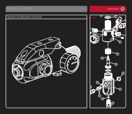
MINI-REGULATOR SERVICE (2nd Stage Regulator)<br />
2<br />
3<br />
5<br />
4<br />
ADHERE STRICTLY TO THESE<br />
AND ALL OTHER SAFETY<br />
INSTRUCTIONS AND GUIDELINES<br />
• Ensure a barrel blocking device is fitted to the <strong>ANGEL</strong>.<br />
• Ensure the hopper is removed from the <strong>ANGEL</strong>.<br />
• Ensure that there are no paintballs in the <strong>ANGEL</strong>.<br />
• Always remove the first stage regulator and relieve all residual gas pressure<br />
from the <strong>ANGEL</strong> before disassembly.<br />
• The <strong>ANGEL</strong> can hold a small residual charge of gas, typically 2 shots, with the<br />
first stage regulator removed. Always discharge the marker in a safe direction<br />
to relieve this residual gas pressure.<br />
WARNING<br />
1<br />
The mini-regulator is a second stage regulator that is used to control the velocity<br />
and regulate the gas pressure. It can be deleted, but only if a suitable first stage<br />
regulator is used that incorporates a high flow and good regulation properties<br />
across the tank pressure range.<br />
• Remove the macro line hose from the mini regulator by following the<br />
procedure and warnings given in PROPELLANT AIR/NITROGEN SUPPLY<br />
- Page 4.<br />
• Remove the mini-regulator adjuster screw 1.<br />
• Remove the mini regulator locking screw 2.<br />
• Remove the mini regulator end cap 3 by inserting a M4 allen key into the<br />
macro line fitting 4 and rotating counter clockwise.<br />
• Insert an M3 screw into the threaded hole in the bottom of the spool and<br />
gently extract the spool 5.<br />
• Remove the circlip 6 located in the spool using suitable circlip pliers.<br />
• Invert the mini-regulator spool and tap it down firmly onto a smooth surface to<br />
shock the internals out of the mini-regulator body.<br />
• Ensure the large piston 7, Spring stack 8, small piston 9 , and the ball<br />
bearing are removed.<br />
• Inspect the O rings for damage and replace if necessary.<br />
• Inspect the small piston 9 face seal for damage and replace the whole small<br />
piston if necessary.<br />
• Inspect the large piston 7 and small piston 9 sealing faces for damage and<br />
replace as necessary.<br />
SPRING STACK<br />
ORDER<br />
10<br />
9<br />
8 8<br />
IMPORTANT NOTES: For re-assembly of components<br />
• Due care and attention must be shown to ensure you do not score or<br />
damage the bores within the mini-regulator body whilst performing<br />
maintenance.<br />
• If the small piston or large piston seal faces are damaged they must be<br />
replaced.<br />
• We recommend that you lubricate the parts during re-assembly with Love<br />
Juice Extreme Grease.<br />
• Ensure the spring stack is in the correct order.<br />
• Ensure the circlip is re-located correctly in the groove.<br />
• Ensure you follow the procedure and warnings given in PROPELLANT AIR/<br />
ANTI - DOUBLE BALL DETENT SERVICE<br />
1 2 3<br />
1 2<br />
3<br />
WARNING<br />
7 6<br />
3<br />
2<br />
1<br />
ADHERE STRICTLY TO THESE<br />
AND ALL OTHER SAFETY<br />
INSTRUCTIONS AND GUIDELINES<br />
• Ensure a barrel blocking device is fitted to the <strong>ANGEL</strong>.<br />
• Ensure the hopper is removed from the <strong>ANGEL</strong>.<br />
• Ensure that there are no paintballs in the <strong>ANGEL</strong>.<br />
• Always remove the first stage regulator and relieve all residual gas pressure<br />
from the <strong>ANGEL</strong> before disassembly.<br />
• The <strong>ANGEL</strong> can hold a small residual charge of gas, typically 2 shots, with the<br />
first stage regulator removed. Always discharge the marker in a safe direction<br />
to relieve this residual gas pressure.<br />
There are two anti-double ball assemblies that can be removed and the internal<br />
parts serviced if necessary. These are located on either side of the body below<br />
the feed tube.<br />
• Using a 2.0mm Allen key, remove the covers 1.<br />
• Remove the spring 2.<br />
• Remove the anti-double ball 3.<br />
• Repeat for other side.<br />
• Inspect parts and replace if necessary.<br />
IMPORTANT NOTES: For re-assembly of components<br />
• Ensure the anti-double ball is re-located correctly.<br />
• Ensure the spring is located correctly onto the anti-double ball.<br />
• Ensure the anti-double ball covers are inserted correctly into the <strong>ANGEL</strong><br />
body.<br />
• Ensure that the Angel Eyes are not moved or trapped.<br />
© 2005 WDP LTD.
16 <strong>ANGEL</strong> <strong>G7</strong><br />
MAINTENANCE<br />
<strong>ANGEL</strong> Eyes Service & Removal<br />
<strong>ANGEL</strong> EYES<br />
7 6<br />
1 2 3 4<br />
5<br />
8 8<br />
ADHERE STRICTLY TO THESE<br />
AND ALL OTHER SAFETY<br />
INSTRUCTIONS AND GUIDELINES<br />
• Ensure a barrel blocking device is fitted to the <strong>ANGEL</strong>.<br />
• Ensure the hopper is removed from the <strong>ANGEL</strong>.<br />
• Ensure that there are no paintballs in the <strong>ANGEL</strong>.<br />
• Always remove the first stage regulator and relieve all residual gas pressure<br />
from the <strong>ANGEL</strong> before disassembly.<br />
• The <strong>ANGEL</strong> can hold a small residual charge of gas, typically 2 shots, with the<br />
first stage regulator removed. Always discharge the marker in a safe direction<br />
to relieve this residual gas pressure.<br />
WARNING<br />
The <strong>ANGEL</strong> uses a dual optical eye (break beam) system to detect when a ball is<br />
in position and ready to fire.<br />
SERVICE Prior to servicing the Angel Eyes you should carry out the Angel Eye<br />
test to ensure that they are not functioning prior to servicing. See Angel Eye<br />
Test - Right. The Angel Eyes are located under the same cover plates as the<br />
anti double balls and the internal parts can be serviced if necessary. These are<br />
located on either side of the body below the feed tube.<br />
• Using a 2.0mm Allen key, remove the covers 1.<br />
• Remove the anti double ball assembly 2 3.<br />
• Carefully remove the rubber protective strap from its location 4.<br />
• Carefully extract the Angel Eye 5 from its location hole and clean if necessary.<br />
• NOTE: The Angel Eyes sensor MUST NOT be PULLED out of the body by the<br />
ribbon cable, the sensor MUST be PUSHED out using a suitable blunt pick<br />
from within the body.<br />
• Inspect parts and clean if necessary.<br />
IMPORTANT NOTES: For re-assembly of components<br />
• Ensure the anti-double ball is re-located correctly.<br />
• Ensure the spring is located correctly onto the anti-double ball.<br />
• Ensure the cover plates are inserted correctly into the <strong>ANGEL</strong> body<br />
• Ensure that the Angel Eyes are not moved or trapped.<br />
9<br />
WARNING<br />
ADHERE STRICTLY TO THESE<br />
AND ALL OTHER SAFETY<br />
INSTRUCTIONS AND GUIDELINES<br />
• Ensure a barrel blocking device is fitted to the <strong>ANGEL</strong>.<br />
• Ensure the hopper is removed from the <strong>ANGEL</strong>.<br />
• Ensure that there are no paintballs in the <strong>ANGEL</strong>.<br />
• Always remove the first stage regulator and relieve all residual gas pressure<br />
from the <strong>ANGEL</strong> before disassembly.<br />
• The <strong>ANGEL</strong> can hold a small residual charge of gas, typically 2 shots, with the<br />
first stage regulator removed. Always discharge the marker in a safe direction<br />
to relieve this residual gas pressure.<br />
<strong>ANGEL</strong> EYES REMOVAL<br />
• Remove the grip cheek cover by removing the 6 retaining screws using a<br />
metric 2.5mm A/F Allen key.<br />
• Unplug the battery and solenoid plugs from the PCB 6.<br />
• Remove the Angel Eyes ribbon cable 7 from the ZIF socket on the<br />
circuit board.<br />
• Remove the Anti double ball covers 1,2,3 using a metric 2.0 mm<br />
A/F Allen key.<br />
• Remove the Angel Eyes Shields 4 and its sensors 5 from the body.<br />
• Remove the 2 grip frame screws 8 holding the frame to the body using a<br />
suitable 3mm A/F Allen key.<br />
• Remove the grip frame from the body 9.<br />
NOTE: The Angel Eyes sensor MUST NOT be PULLED out of the body by the<br />
ribbon cable, the sensor MUST be PUSHED out using a suitable blunt<br />
pick from within the body.<br />
IMPORTANT NOTES: For re-assembly of components<br />
• Ensure no wires become trapped between the body and grip frame during<br />
re-assembly.<br />
• Ensure the plugs are located in the correct sockets.<br />
© 2005 WDP LTD.
LPR Adjustment<br />
MAINTENANCE<br />
<strong>ANGEL</strong> <strong>G7</strong><br />
17<br />
LPR ADJUSTMENT<br />
3<br />
SPRING STACK<br />
ORDER<br />
4<br />
1 2 3<br />
ADHERE STRICTLY TO THESE<br />
AND ALL OTHER SAFETY<br />
INSTRUCTIONS AND GUIDELINES<br />
• Ensure a barrel blocking device is fitted to the <strong>ANGEL</strong>.<br />
• Ensure the hopper is removed from the <strong>ANGEL</strong>.<br />
• Ensure that there are no paintballs in the <strong>ANGEL</strong>.<br />
• Always remove the first stage regulator and relieve all residual gas pressure<br />
from the <strong>ANGEL</strong> before disassembly.<br />
• The <strong>ANGEL</strong> can hold a small residual charge of gas, typically 2 shots, with the<br />
first stage regulator removed. Always discharge the marker in a safe direction<br />
to relieve this residual gas pressure.<br />
WARNING<br />
The low-pressure regulator controls the pneumatic cycle of the <strong>ANGEL</strong> and is<br />
located in the left-hand chamber at the front of the <strong>ANGEL</strong> body. The pressure<br />
needs to be at 65 PSI (4.5bar) output at a pressure of 350 PSI at the second<br />
stage regulator.<br />
LPR adjustment is achieved by the removal of shims. Each shim<br />
equalsapproximately 2 PSI / 0.14 BAR. We recommend the use of the optional<br />
service tools and lubrication of parts with Love Juice Extreme Grease only. See<br />
General Assembly diagrams - pages 10-11.<br />
• Ensure the <strong>ANGEL</strong> is de-gassed and switched OFF.<br />
• Remove the left end cap 1 using suitable metric 4.0 A/F Allen key.<br />
• Insert the optional pressure gauge adaptor into the hole that the end cap 1<br />
was removed from.<br />
• Re-Gas the <strong>ANGEL</strong> and switch the isolator switch ON.<br />
WARNING<br />
ADHERE STRICTLY TO THESE<br />
AND ALL OTHER SAFETY<br />
INSTRUCTIONS AND GUIDELINES<br />
• Always remove the first stage regulator and relieve all residual gas pressure<br />
from the <strong>ANGEL</strong> before disassembly.<br />
• The <strong>ANGEL</strong> can hold a small residual charge of gas, typically 2 shots, with the<br />
first stage regulator removed. Always discharge the marker in a safe direction<br />
to relieve this residual gas pressure.<br />
• Ensure the <strong>ANGEL</strong> is de-gassed and switched OFF.<br />
• Remove the pressure gauge adaptor and insert an M 4.0 mm screw or the<br />
piston extracting tool (optional extra) into the brass piston 2 and withdraw<br />
slowly.<br />
• Remove the 3 tri-activ piston springs 3.<br />
• Add or subtract shims 4 as necessary, note the number of shims may vary<br />
from the diagram shown (maximum 20).<br />
• Replace the 3 tri-activ springs 3 in correct order onto the piston 2.<br />
• Re-insert the piston 2 ensuring that it is located correctly.<br />
• Insert the optional pressure gauge adaptor into the hole that the end cap 1<br />
was removed from.<br />
• Re-Gas the <strong>ANGEL</strong> and switch the isolator switch ON.<br />
ADHERE STRICTLY TO THESE<br />
AND ALL OTHER SAFETY<br />
INSTRUCTIONS AND GUIDELINES<br />
• THE <strong>ANGEL</strong> IS LIVE AND CAPABLE OF DISCHARGING.<br />
WARNING<br />
Verify the LPR pressure by following the procedure described above. Once the<br />
desired pressure has been achieved proceed to the next stage.<br />
ADHERE STRICTLY TO THESE<br />
AND ALL OTHER SAFETY<br />
INSTRUCTIONS AND GUIDELINES<br />
• Always remove the first stage regulator and relieve all residual gas pressure<br />
from the <strong>ANGEL</strong> before disassembly.<br />
• The <strong>ANGEL</strong> can hold a small residual charge of gas, typically 2 shots, with the<br />
first stage regulator removed. Always discharge the marker in a safe direction<br />
to relieve this residual gas pressure.<br />
WARNING<br />
• Ensure the <strong>ANGEL</strong> is de-gassed and switched OFF.<br />
•Remove the pressure gauge adaptor & replace the end cap 1.<br />
ADHERE STRICTLY TO THESE<br />
AND ALL OTHER SAFETY<br />
INSTRUCTIONS AND GUIDELINES<br />
• THE <strong>ANGEL</strong> IS LIVE AND CAPABLE OF DISCHARGING.<br />
WARNING<br />
• Fire 6 shots with NO paintballs present to stabilize the LPR pressure. Note<br />
the pressure reading. Should the reading be too high or low, proceed to the<br />
next stage.<br />
© 2005 WDP LTD.
18 <strong>ANGEL</strong> <strong>G7</strong><br />
MAINTENANCE<br />
LPR Assembly Removal - LPR Main Seal Replacement<br />
LPR ASSEMBLY REMOVAL<br />
LPR MAIN SEAL REPLACEMENT<br />
6<br />
5 7 8 9 43<br />
2<br />
7<br />
1<br />
IMPORTANT NOTES: For re-assembly of components<br />
• Care must be taken so that the bore is not scored or the seals damaged.<br />
• Ensure the LPR’s pin location hole is aligned with the pin retaining hole<br />
within<br />
the <strong>ANGEL</strong> body prior to insertion.<br />
• Ensure the spring stack is inserted in the correct order.<br />
• We recommend that you verify your LPR pressure if it has been removed.<br />
See LPR ADJUSTMENT - Page 14.<br />
• Ensure the end cap is located correctly.<br />
• Ensure the springs or shims are not lost (see LPR assembly).<br />
Insert or remove shims as necessary.<br />
• Each shim equals approximately 2 PSI/0.14BAR.<br />
RADIUS<br />
4<br />
6 5<br />
6 5 4<br />
3<br />
2<br />
2<br />
SPRING STACK<br />
ORDER<br />
1<br />
SPRING STACK<br />
ORDER<br />
ADHERE STRICTLY TO THESE<br />
AND ALL OTHER SAFETY<br />
INSTRUCTIONS AND GUIDELINES<br />
• Ensure a barrel blocking device is fitted to the <strong>ANGEL</strong>.<br />
• Ensure the hopper is removed from the <strong>ANGEL</strong>.<br />
• Ensure that there are no paintballs in the <strong>ANGEL</strong>.<br />
• Always remove the first stage regulator and relieve all residual gas pressure<br />
from the <strong>ANGEL</strong> before disassembly.<br />
• The <strong>ANGEL</strong> can hold a small residual charge of gas, typically 2 shots, with the<br />
first stage regulator removed. Always discharge the marker in a safe direction<br />
to relieve this residual gas pressure.<br />
WARNING<br />
• Remove the mini regulator spool as per mini regulator service - Page 12 .<br />
• Remove the fore grip body internal retaining screw 1 using a 4.0mm<br />
A/F Allen key.<br />
• Remove fore grip body external retaining screw 2 using a 3.0mm<br />
A/F Allen key.<br />
• Ensure the O ring 3 is not lost.<br />
• Remove LPR retaining pin using suitable grips 4.<br />
• Remove the right end cap 5 using suitable metric 4.0mm A/F Allen key.<br />
• Insert an M 2.5mm screw or the piston extracting tool (optional extra)<br />
into the brass piston 6 and withdraw slowly.<br />
• Remove the 3 tri-active piston spring stack 7.<br />
• Remove the shims 8 - Note: the number of shims may vary from shown<br />
diagram.<br />
• Using a suitable blunt pick, carefully withdraw the LPR body 9.<br />
The LPR may be serviced once it has been removed by following the LPR<br />
ASSEMBLY REMOVAL - Left. The serviceable parts are the external O rings and<br />
the internal main seal.<br />
• Remove the LPR piston 1.<br />
• Remove the LPR spring stack 2 noting the order.<br />
• Remove the LPR shims 3 Note: the number of shims may vary from shown<br />
diagram.<br />
• Remove the LPR main seal retainer nut 6 from the LPR body 4 using a<br />
suitable tool. To prevent the body from rotating in your hand you may insert<br />
the LPR lock pin into the LPR body to give some leverage.<br />
• Remove the main seal 5 noting the radius on the edge of the seal.<br />
• Discard the main seal 5 and replace with new item.<br />
IMPORTANT NOTES: For re-assembly of components<br />
• Ensure the new main seal is replaced with the radius edge going in first.<br />
• Ensure the seal retainer nut is tight and flush with the LPR body.<br />
• Ensure the spring stack is in the correct order.<br />
• Ensure that the LPR pressure is reset as per LPR ADJUSTMENT - Page 14.<br />
© 2005 WDP LTD.
Exhuast Guide Removal - Exhaust Valve Stem Removal<br />
MAINTENANCE<br />
<strong>ANGEL</strong> <strong>G7</strong><br />
19<br />
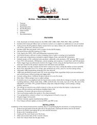
EXHAUST GUIDE REMOVAL<br />
EXHAUST VALVE STEM REMOVAL<br />
3<br />
4<br />
5 2<br />
1<br />
1<br />
4<br />
WARNING<br />
ADHERE STRICTLY TO THESE<br />
AND ALL OTHER SAFETY<br />
INSTRUCTIONS AND GUIDELINES<br />
• Ensure a barrel blocking device is fitted to the <strong>ANGEL</strong>.<br />
• Ensure the hopper is removed from the <strong>ANGEL</strong>.<br />
• Ensure that there are no paintballs in the <strong>ANGEL</strong>.<br />
• Always remove the first stage regulator and relieve all residual gas pressure<br />
from the <strong>ANGEL</strong> before disassembly.<br />
• The <strong>ANGEL</strong> can hold a small residual charge of gas, typically 2 shots, with the<br />
first stage regulator removed. Always discharge the marker in a safe direction<br />
to relieve this residual gas pressure.<br />
• Remove the grip cheek cover by removing the 6 retaining screws<br />
using a metric 2.5mm A/F Allen key.<br />
• Unplug the Angel Eyes, battery and solenoid plugs.<br />
• Remove the 2 grip frame screws holding the frame to the body using a<br />
suitable 3mm A/F Allen key.<br />
• Remove the grip frame 1 from the body.<br />
• Pull out the exhaust valve retaining pin 2 located in the body using suitable grips.<br />
• Remove the left end cap 3 using suitable metric 4.0mm A/F Allen key.<br />
• Remove the valve spring assembly 4 that includes the support bobbin, valve<br />
spring and exhaust valve stem.<br />
• Using a suitable blunt hooked pick carefully retract exhaust valve guide 5<br />
by inserting the pick into the exhaust valve hole that the exhaust valve stem<br />
located into.<br />
• Inspect and service parts as necessary.<br />
IMPORTANT NOTES: For re-assembly of components<br />
• Care must be taken so that the bore is not scored or the seals damaged.<br />
• Ensure the exhaust valve guide body is free from damage that may score<br />
the bore.<br />
• Ensure you do not damage the exhaust valve guide sealing face.<br />
• Ensure the location hole in the exhaust valve guide is in the correct<br />
orientation to the lock hole within the main body prior to refitting.<br />
• Slowly insert the valve guide pushing it down with a blunt soft faced rod.<br />
• When the holes line up insert the lock pin into the hole.<br />
• Ensure no wires become trapped between the body and grip frame during<br />
re-assembly.<br />
• Ensure the plugs are located in the correct sockets.<br />
ADHERE STRICTLY TO THESE<br />
AND ALL OTHER SAFETY<br />
INSTRUCTIONS AND GUIDELINES<br />
• Ensure a barrel blocking device is fitted to the <strong>ANGEL</strong>.<br />
• Ensure the hopper is removed from the <strong>ANGEL</strong>.<br />
• Ensure that there are no paintballs in the <strong>ANGEL</strong>.<br />
• Always remove the first stage regulator and relieve all residual gas pressure<br />
from the <strong>ANGEL</strong> before disassembly.<br />
• The <strong>ANGEL</strong> can hold a small residual charge of gas, typically 2 shots, with the<br />
first stage regulator removed. Always discharge the marker in a safe direction<br />
to relieve this residual gas pressure.<br />
WARNING<br />
The exhaust valve stem is a consumable item that will eventually wear out.<br />
Premature failure of the exhaust valve stem is caused by dirty air or failure to<br />
lubricate it at service intervals, to replace the exhaust valve stem follow the<br />
procedures listed below.<br />
• Remove the left end cap 1<br />
• Remove the valve spring assembly 4 that includes the support bobbin, valve<br />
spring and exhaust valve stem.<br />
IMPORTANT NOTES: For re-assembly of components<br />
• Ensure exhaust valve assembly is located in the exhaust body within the<br />
<strong>ANGEL</strong>.<br />
• Ensure the end cap is located correctly.<br />
© 2005 WDP LTD.
20 <strong>ANGEL</strong> <strong>G7</strong><br />
MAINTENANCE<br />
RAM Removal<br />
RAM REMOVAL<br />
2<br />
9<br />
8<br />
7<br />
8<br />
WARNING<br />
5<br />
4<br />
3<br />
ADHERE STRICTLY TO THESE<br />
AND ALL OTHER SAFETY<br />
INSTRUCTIONS AND GUIDELINES<br />
• Ensure a barrel blocking device is fitted to the <strong>ANGEL</strong>.<br />
• Ensure the hopper is removed from the <strong>ANGEL</strong>.<br />
• Ensure that there are no paintballs in the <strong>ANGEL</strong>.<br />
• Always remove the first stage regulator and relieve all residual gas pressure<br />
from the <strong>ANGEL</strong> before disassembly.<br />
• The <strong>ANGEL</strong> can hold a small residual charge of gas, typically 2 shots, with the<br />
first stage regulator removed. Always discharge the marker in a safe direction<br />
to relieve this residual gas pressure.<br />
1<br />
IMPORTANT NOTES: For re-assembly of components<br />
• There are wires and a spring located under the back plate. Care must be<br />
taken so that the wires are not pulled or trapped during maintenance.<br />
• Ensure the ram assembly is lubricated with Love Juice Extreme Grease prior<br />
to re-fitment.<br />
• Ensure the ram assembly external O rings are not damaged.<br />
• Ensure the ram assembly is inserted slowly to prevent damage to the<br />
O rings.<br />
• See RAM STROKE ADJUSTMENT - Left, for setting the ram position.<br />
• Ensure the <strong>ANGEL</strong> is de-gassed and switched OFF.<br />
• Ensure the <strong>ANGEL</strong> isolator switch is in the OFF position or the <strong>ANGEL</strong> is in<br />
SAFE mode.<br />
• Rotate the breech lock lever 1 clockwise until it stops.<br />
• Swing out the Rotor Breech block 2 so that the bolt is exposed.<br />
NOTE the breech will not open the Angel is degassed and the bolt is in the<br />
forward position.<br />
• If the bolt is in the forward position even if the breech lock lever has been<br />
rotated either ensure the angel is gassed up or push the bolt back with a<br />
squeegee.<br />
• Remove the breech lock lever by unscrewing the locking screw 3<br />
counter-clockwise.<br />
• Remove the screw located in the centre of the back plate 4, using a suitable<br />
2.0mm A/F metric Allen key.<br />
• Carefully lift the back plate off 5.<br />
• Remove the grip cheek cover 7 by removing the 6 retaining screws<br />
using a metric 2.5mm A/F Allen key.<br />
• Unplug the Angel Eyes, battery and solenoid plugs.<br />
• Remove the 2 grip frame screws 8 holding the frame to the body using<br />
a suitable 3mm A/F Allen key.<br />
• Remove the grip frame 9 from the body.<br />
• Withdraw the ram lock pin located under the frame. The ram can now<br />
be withdrawn as an assembly.<br />
© 2005 WDP LTD.
OPTO Board - Vernier Trigger Adjustment<br />
MAINTENANCE<br />
<strong>ANGEL</strong> <strong>G7</strong><br />
21<br />
OPTO BOARD<br />
VERNIER TRIGGER ADJUSTMENTS<br />
4 3<br />
1<br />
• Further fine tuning can be achieved by adjusting the toe adjuster screw 2.<br />
Clockwise will cause the trigger to activate with less trigger movement counter<br />
clockwise will result in a longer trigger stroke within the limits set by vernier<br />
thumb wheels.<br />
• Verify the trigger is functioning correctly.<br />
• Replace grip cheek cover screws using a suitable metric Allen key.<br />
• Very gently tighten the vernier thumb wheel locking screw.<br />
ADHERE STRICTLY TO THESE<br />
AND ALL OTHER SAFETY<br />
INSTRUCTIONS AND GUIDELINES<br />
• Do not attempt to modify the OPTO board assembly in any way as this will<br />
invalidate your warranty and could lead to safety concerns.<br />
WARNING<br />
The <strong>ANGEL</strong> incorporates the OPTO board. This is the latest development<br />
in trigger sensing function. It achieves unsurpassed advancements in trigger<br />
repeatability and sensitivity, its non-mechanical switching results in faster,<br />
shorter and lighter trigger strokes that give the user higher prolonged achievable<br />
rates of fire.<br />
IMPORTANT NOTES:<br />
• When accessing the Internal Tournament LED menus the OPTO board<br />
should not be exposed to direct sunlight or strong external sources of light<br />
without the grip cheek fitted as this light will induce a safety feature, that<br />
will prevent the <strong>ANGEL</strong> from firing whilst it remains exposed to the strong<br />
external light.<br />
• The OPTO board is a non-mechanical switch that is silent in its operation<br />
and no audible click is present.<br />
2<br />
WARNING<br />
ADHERE STRICTLY TO THESE<br />
AND ALL OTHER SAFETY<br />
INSTRUCTIONS AND GUIDELINES<br />
• Ensure a barrel blocking device is fitted to the <strong>ANGEL</strong>.<br />
• Ensure the hopper is removed from the <strong>ANGEL</strong>.<br />
• Ensure that there are no paintballs in the <strong>ANGEL</strong>.<br />
• Always remove the first stage regulator and relieve all residual gas pressure<br />
from the <strong>ANGEL</strong> before disassembly.<br />
• The <strong>ANGEL</strong> can hold a small residual charge of gas, typically 2 shots, with the<br />
first stage regulator removed. Always discharge the marker in a safe direction<br />
to relieve this residual gas pressure.<br />
• Never adjust your trigger so fine that accidental discharge can occur due to<br />
shock loads or vibration.<br />
The trigger return stroke, over-travel and toe adjustments should be carried<br />
out in the order shown and will enable the user to have total adjustment on the<br />
tactile feel and trigger movement.<br />
• Using a suitable Allen key undo the trigger adjustment locking screw 1<br />
located between the thumb wheels by rotating counter clockwise.<br />
• Remove the grip cheek retaining screws and expose the circuit board<br />
• Using a suitable Allen key back off the toe adjustment screw 2 by rotating<br />
counter clockwise, now the trigger return stroke and over travel may be set.<br />
• The vernier thumb wheel located at the top of the grip frame closest to therear<br />
of the <strong>ANGEL</strong> 3 controls the over-travel<br />
• By viewing the <strong>ANGEL</strong> on the left hand side of the body rotate the thumb<br />
wheel closest to the rear of the <strong>ANGEL</strong> slowly towards the rear of the <strong>ANGEL</strong><br />
each click at a time, this will reduces the over travel each click will be an<br />
incremental reduction in the stroke.<br />
• The vernier thumb wheel located at the top of the grip frame furthest to the<br />
rear of the <strong>ANGEL</strong> 4 controls the return stroke.<br />
• By viewing the <strong>ANGEL</strong> on the left hand side of the body rotate the thumb<br />
wheel furthest from the rear of the <strong>ANGEL</strong> slowly towards the rear of the<br />
<strong>ANGEL</strong> each click at a time, this will reduces the return stroke, each clickwill<br />
be an incremental reduction in the stroke.<br />
IMPORTANT NOTES: For re-assembly of components<br />
• There must be sufficient over travel to activate the OPTO board, otherwise<br />
the opto-trigger will not operate correctly<br />
• There must be sufficient return stroke to reset the OPTO board otherwise the<br />
opto-trigger will not operate correctly.<br />
• Should the trigger be incorrectly adjusted, re-adjust the return stroke<br />
by repeating the procedures listed above or re-adjust the over travel by<br />
repeating the procedures listed above.<br />
• When adjusting the trigger stroke we recommend you apply a small amount<br />
of Loctite low strength thread lock to the toe adjuster screw to prevent<br />
movement due to vibration prior to adjustment.<br />
• The toe adjuster screw must not be over-adjusted as damage may occur to<br />
the actuation.<br />
• The vernier locking screw must not be over tightened otherwise damage may<br />
occur to the vernier retention springs.<br />
• The OPTO board is a non-mechanical switch that is silent in its operation<br />
and no audible click is present.<br />
• The OPTO board should not be exposed to direct sunlight or external strong<br />
sources of light without the grip cheek fitted as this light will induce a safety<br />
feature, that will prevents the <strong>ANGEL</strong> from firing whilst it remains exposed to<br />
the external strong light.<br />
• Never adjust the trigger stroke so that the trigger has so fine a movement<br />
that accidental discharges may occur or that trigger bounce may occur<br />
leading to accidental discharges.<br />
© 2005 WDP LTD.
22 <strong>ANGEL</strong> <strong>G7</strong><br />
MAINTENANCE<br />
Vernier Trigger Removal<br />
VERNIER TRIGGER WHEEL REMOVAL<br />
1<br />
A<br />
A<br />
1<br />
7<br />
2<br />
1<br />
3<br />
5<br />
4<br />
6<br />
5<br />
1<br />
6<br />
WARNING<br />
3<br />
ADHERE STRICTLY TO THESE<br />
AND ALL OTHER SAFETY<br />
INSTRUCTIONS AND GUIDELINES<br />
• Ensure a barrel blocking device is fitted to the <strong>ANGEL</strong>.<br />
• Ensure the hopper is removed from the <strong>ANGEL</strong>.<br />
• Ensure that there are no paintballs in the <strong>ANGEL</strong>.<br />
• Always remove the first stage regulator and relieve all residual gas pressure<br />
from the <strong>ANGEL</strong> before disassembly.<br />
• The <strong>ANGEL</strong> can hold a small residual charge of gas, typically 2 shots, with the<br />
first stage regulator removed. Always discharge the marker in a safe direction<br />
to relieve this residual gas pressure.<br />
• Never adjust your trigger so fine that accidental discharge can occur due to<br />
shock loads or vibration.<br />
IMPORTANT NOTES: For re-assembly of components<br />
• Should you be unsure of the original position of the vernier wheels follow the<br />
procedure listed below for re-assembly.<br />
• Ensure the vernier wheel locking screws 1 are backed off by rotating<br />
counter clockwise.<br />
• Ensure the vernier trigger toe adjuster screw is backed off by rotating<br />
counter clockwise.<br />
• It is important that the vernier wheels are inserted in position A shown<br />
above, wheel 5 with the small magnet towards the back of the <strong>ANGEL</strong>.<br />
Wheel 6 with the large magnet towards the front of the <strong>ANGEL</strong>, this is to<br />
ensure that you start with maximum range of adjustment<br />
• Verify the correct vernier wheel position by the indicators on the wheels 5<br />
• Re-attach the frame.<br />
• Ensure no wires become trapped between the body and grip frame during<br />
re-assembly.<br />
• Ensure the plugs are located in the correct sockets.<br />
• Adjust the trigger as VERNIER TRIGGER ADJUSTMENT - Page 18.<br />
• Undo the vernier wheel lock screws 1 using a suitable allen key.<br />
• Important: Note the vernier wheels position prior to removal.<br />
• Remove the grip cheek cover by removing the 6 retaining screws and using a<br />
metric 2.5mm A/F Allen key.<br />
• Unplug the Angel Eyes, battery and solenoid plugs 2.<br />
• Remove the 2 grip frame screws 3 holding the frame to the body using a<br />
suitable 3mm A/F Allen key.<br />
• Remove the grip frame 4 from the body.<br />
• Gently remove the vernier wheels 5,6 from the body.<br />
• Remove the vernier wheel ratchet plates 7 and inspect for damage.<br />
© 2005 WDP LTD.
Battery Vernier Removal Trigger - Wiring Wheel Connections Removal<br />
MAINTENANCE<br />
<strong>ANGEL</strong> <strong>G7</strong><br />
23<br />
BATTERY REMOVAL<br />
6<br />
3<br />
• Carefully feed the battery plug 9 and the solenoid plug that was inserted into<br />
the PCB though the <strong>ANGEL</strong> body and withdraw the wires from the rear of the<br />
<strong>ANGEL</strong>.<br />
• Remove the battery spacer from the battery cavity.<br />
• Carefully withdraw the metal hydride battery 7 from the <strong>ANGEL</strong> body.<br />
• Re-assemble in reverse order.<br />
WIRING CONNECTIONS<br />
<strong>ANGEL</strong> EYES SOLENOID HOPPER BATTERY<br />
7<br />
5<br />
2 2 1<br />
4<br />
IMPORTANT NOTES: For re-assembly of components<br />
• Do not pull or apply excessive force to the wires.<br />
• Do not trap any wiring or damage will occur to the wiring resulting in a fault<br />
developing.<br />
• Do not attempt to disassemble the battery stick.<br />
• Ensure that when the switch is replaced that it is rotated so that the ON<br />
position is as per the diagram in the section SWITCHING ON YOUR <strong>ANGEL</strong><br />
- Page 3.<br />
ADHERE STRICTLY TO THESE<br />
AND ALL OTHER SAFETY<br />
INSTRUCTIONS AND GUIDELINES<br />
• Ensure a barrel blocking device is fitted to the <strong>ANGEL</strong>.<br />
• Ensure the hopper is removed from the <strong>ANGEL</strong>.<br />
• Ensure that there are no paintballs in the <strong>ANGEL</strong>.<br />
• Always remove the first stage regulator and relieve all residual gas pressure<br />
from the <strong>ANGEL</strong> before disassembly.<br />
• The <strong>ANGEL</strong> can hold a small residual charge of gas, typically 2 shots, with the<br />
first stage regulator removed. Always discharge the marker in a safe direction<br />
to relieve this residual gas pressure.<br />
WARNING<br />
The battery is a metal hydride 4.8 volt stick and is an item that will wear out<br />
with time dependant on the number of charges/discharges it has completed.<br />
An indication of a worn battery is that it will not charge fully or that it will<br />
not hold a charge for a prolonged period. To replace the battery, follow the<br />
procedure below.<br />
• Remove the grip cheek cover by removing the 6 retaining screws using a<br />
metric 2.5mm A/F Allen key.<br />
• Unplug the Angel Eyes, battery and solenoid plugs from the PCB 1.<br />
• Remove the grip frame screws 1 holding the frame to the body using a<br />
suitable 3mm A/F Allen key.<br />
• Remove the grip frame 2 from the body.<br />
• Remove the breech lock lever 3 by unscrewing the locking screw 4<br />
counter-clockwise.<br />
• Remove the screw 5 located in the centre of the back plate 6 using a<br />
suitable 2.0mm A/F metric Allen key.<br />
• Carefully lift the back plate 6 off .<br />
WARNING<br />
ADHERE STRICTLY TO THESE<br />
AND ALL OTHER SAFETY<br />
INSTRUCTIONS AND GUIDELINES<br />
• Ensure a barrel blocking device is fitted to the <strong>ANGEL</strong>.<br />
• Ensure the hopper is removed from the <strong>ANGEL</strong>.<br />
• Ensure that there are no paintballs in the <strong>ANGEL</strong>.<br />
• Always remove the first stage regulator and relieve all residual gas pressure<br />
from the <strong>ANGEL</strong> before disassembly.<br />
• The <strong>ANGEL</strong> can hold a small residual charge of gas, typically 2 shots, with the<br />
first stage regulator removed. Always discharge the marker in a safe direction<br />
to relieve this residual gas pressure.<br />
• Ensure the <strong>ANGEL</strong> is de-gassed and switched off.<br />
• Remove the left-hand side grip cheek cover by removing the 3 screws<br />
using a suitable metric Allen key.<br />
• Access to the PCB connections is now gained.<br />
IMPORTANT NOTES: For re-assembly of components<br />
• Do not trap any wiring or damage could occur to the wiring resulting in a<br />
fault developing.<br />
• Do not pull the plugs out from the PCB by the wiring use a suitable tool.<br />
© 2005 WDP LTD.
24 <strong>ANGEL</strong> <strong>G7</strong><br />
APPENDICES<br />
Fault Finding Table – Useful Conversions<br />
FAULT FINDING TABLE<br />
PROBLEM SOLUTION PAGE<br />
<strong>ANGEL</strong> WILL NOT FIRE<br />
No air or nitrogen present? Propellant Air/Nitrogen Supply . 4<br />
Is the battery pack charged? Charging the <strong>ANGEL</strong> 3<br />
The battery is not charging. Check vehicle voltage. –<br />
Is the <strong>ANGEL</strong> in ‘SAFE’ Making the <strong>ANGEL</strong> ‘LIVE’. 4<br />
Is the isolator switched off? Switching the <strong>ANGEL</strong> On. 4<br />
Is the trigger not closing the switch? Trigger Adjustment. 21<br />
Is the trigger not releasing the switch? Trigger Adjustment. 21<br />
Is the bolt jammed forward? Clear the blockage from breech. –<br />
Is the LPR set correctly? LPR Adjustment. 17<br />
Is the OPTO Trigger functioning? Trigger Adjustment. 21<br />
Are the connectors plugged in correctly? Wiring Connections 23<br />
Are the Angel Eyes switched on? Ensure paint is present –<br />
Are the Angel Eyes optics blocked Clean the Angel Eyes Optics –<br />
VELOCITY VARIATIONS<br />
Are good quality paintballs been used? Use good paintballs. –<br />
Is the barrel bore correct for the paint? Use suitable barrel. –<br />
Is the paint swollen, cold or hot? Review your storage of paint. –<br />
Is the barrel bore clean? Clean the barrel. –<br />
Are the Anti-Double balls sticking? Check Anti-Double Ball 15<br />
Is the tank reg choking on gas supply? Check tank regulator assembly. 4<br />
Is the tank reg operating correctly? Check tank regulator assembly. 4<br />
Is the mini-reg operating correctly? Mini-Regulator Service. 15<br />
Is the mini-reg choking on gas supply? Mini-Regulator Service. 15<br />
Are unsuitable after market parts fitted? Use genuine <strong>ANGEL</strong> parts. –<br />
Is the bolt worn? Replace Soft Bolt. 5<br />
Is the LPR set correctly? LPR Adjustment. 17<br />
Is the valve dwell set correctly? Dwell Adjustment. 10<br />
Is the ram set correctly? Ram Stroke Adjustment. 20<br />
Is first shot low? Increase Dwell Time 10<br />
VELOCITY TOO LOW / HIGH<br />
Is the high pressure reg set correctly? Check at Gas source. 4<br />
Is velocity adjuster screw set correctly? Velocity Adjustment. 6<br />
Is the bolt sticking? Check Anti-Double Ball. 15<br />
Is the LPR set correctly? LPR Adjustment. 17<br />
Is the valve dwell set correctly? Dwell Adjustment. 10<br />
Is the Ram set correctly? Ram Stroke Adjustment. 20<br />
GAS LEAKING<br />
From the back cover? Check solenoid valve. 13<br />
From the Ram assembly? Check ram body O rings. 20<br />
From the gas joints? Check all fittings. 12-14<br />
From exhaust valve? Exhaust valve stem/guide. 19<br />
PROBLEM SOLUTION PAGE<br />
BREAKING PAINTBALLS<br />
Is the paint too fragile? Use less fragile paint. 5<br />
Is the barrel bore correct for the paint? Use suitable barrel. –<br />
Is the paint swollen, cold, hot? Review your storage of paint. –<br />
Are the Angel Eyes switched on? Switching Angel Eyes On 4<br />
Are the Angel Eyes functioning? Angel Eyes Test. 16<br />
Is the loader battery weak/dead? Replace batteries. 5<br />
Is a suitable working loader fitted? See Loader section 5<br />
Is the correct loader setting selected? Change Loader Type settings 7<br />
Is the rate of fire set too high? MROF Adjustment. 9<br />
Is the anti-double balls functioning? Clean or replace. 15<br />
Is the loader suitable for the paint? Change paint colour 5<br />
Is the paint too fragile for the loader? Change paint to tougher grade 5<br />
CHOPPING PAINTBALLS<br />
Is the loader battery weak/dead Replace batteries. 5<br />
Is a suitable working loader fitted? Replace loader. 5<br />
Is the loader dirty? Clean loader. 5<br />
Are the paintballs swollen? Replace the paintballs. –<br />
Are the Angel Eyes switched on? Switching Angel Eyes On 4<br />
Are the Angel Eyes functioning? Angel Eyes Test. 16<br />
Is the correct loader setting selected? Change Loader Type settings 7<br />
Is the Rate Of Fire set too high? MROF Adjustment. 9<br />
Are the Anti-double balls functioning? Clean or replace. 15<br />
FIRING TOO SLOW<br />
Is the rate of fire set correctly? MROF Adjustment. 9<br />
Is the loader battery weak/dead? Replace batteries 5<br />
Is a suitable working loader fitted? Replace loader 5<br />
Is the loader dirty? Clean loader 5<br />
Are the Angel Eyes switched on? Switching Angel Eyes On 4<br />
Is the correct loader setting selected? Change Loader Type settings 7<br />
Is the Rate Of Fire set too low? MROF Adjustment. 9<br />
EXCESSIVE NOISE / GAS CONSUMPTION<br />
Is the valve Dwell set correctly? Dwell Adjustment. 10<br />
Is the LPR pressure set correctly? LPR Adjustment. 17<br />
Is the exhaust valve worn? Exhaust Valve replacement. 19<br />
Is the barrel bore correct for the paint? Use suitable barrel.<br />
USEFUL CONVERSIONS<br />
Listed are some useful conversions relating to pressure, velocity, mass<br />
and distance.<br />
PRESSURE<br />
1 atm = 1.01325 bar<br />
1 atm = 14.6959 psi<br />
1 bar = 14.5038 psi<br />
1 psi = 0.0689476 bar<br />
VELOCITY<br />
1 Ft/s = 0.3048 m/s<br />
1 Ft/s = 0.6818180 Mph<br />
1 m/s = 3.28084 Ft/s<br />
1 m/s = 2.23694 Mph<br />
1 m/s = 3.6 Kph<br />
MASS<br />
1 g = 0.05274 oz<br />
1 Kg = 2.20462 Ib<br />
1 oz = 0.0283495 Kg<br />
DISTANCE<br />
1 mm = 0.0393701 Inch<br />
1 Inch = 25.4mm<br />
1 thou = 25.4 micron<br />
1 micron = 0.0393701 thou<br />
FORMULA TO CONVERT FEET PER SECOND (FT/S)<br />
TO FOOT LBS (FORCE)<br />
1 foot Ibs (force) = 1.35582 Joules<br />
1 Joule = 0.737562 foot Ibs (force)<br />
1 Gram = 15.4324 Grains<br />
1 Grain = 0.000142857 lb<br />
1 lb = 7000 Grains<br />
Velocity squared x Projectile weight<br />
450240<br />
VELOCITY = Ft/s (feet per second)<br />
PROJECTILE WEIGHT = GRAINS<br />
Therefore a paintball @ 3.2grams @ 300Ft/s= 9.9 foot lbs (ftlbs)<br />
© 2005 WDP LTD.
Terms of Warranty: EEC/ROW Excluding USA/Canada<br />
APPENDICES<br />
<strong>ANGEL</strong> <strong>G7</strong><br />
25<br />
TERMS OF WARRANTY - EEC/R.O.W.<br />
EXCLUDING USA / CANADA<br />
Subject to the conditions set out below WDP Ltd. warrants that the <strong>ANGEL</strong><br />
will correspond to its specification at the time of delivery and will be free from<br />
defects in materials and workmanship for a period of six months from the date<br />
of purchase.<br />
WDP Ltd gives this warranty subject to the following conditions:<br />
• Proof of purchase is required in all warranty claims.<br />
• Warranty is not transferable.<br />
• The company shall be under no liability in respect of any defect arising from<br />
fair wear and tear.<br />
• Seals, batteries, wiring, circuit boards, displays and exhaust valves are not<br />
covered by this warranty. Wilful damage, negligence, abnormal working<br />
conditions, weather, accident, tampering, failure to follow manufacturers<br />
instructions (whether oral or in writing), misuse or alteration or repair of the<br />
<strong>ANGEL</strong> without the company’s written approval will invalidate this warranty<br />
and the company shall be under no obligation whatsoever to the purchaser in<br />
respect of any of the above breaches of this warranty.<br />
• The above warranty does not extend to parts, materials or equipment not<br />
manufactured by the company, in respect of which the purchaser shall only<br />
be entitled to the benefit of any such warranty or guarantee as given by the<br />
manufacturer to the company.<br />
This warranty does not cover the following:<br />
• Repairs, alterations or replacements not authorised by the manufacturer.<br />
• The gradual reduction in performance linked to the age of the <strong>ANGEL</strong> or<br />
usage.<br />
• Anything caused directly or indirectly by vandalism or theft.<br />
• Any damage to parts which are recalled by the Manufacturer.<br />
• Any loss, damage or failure, which a qualified engineer appointed by the<br />
Manufacturer, believes could have been avoided or was totally or partly caused<br />
by a lack of maintenance.<br />
Subject as expressly provided in these conditions and except where the goods<br />
are sold to a person dealing as a consumer (within the meaning of the Unfair<br />
Contract Terms Act 1977) all warranties, conditions or other terms implied by<br />
statute or common law are excluded to the fullest extent permitted by law.<br />
Where the goods are sold under a consumer transaction (as defined by the<br />
Unfair Terms in Consumer Contracts Regulations 1994 S13159) the statutory<br />
rights of the purchaser are not affected by these conditions. Carriage charges in<br />
relation to warranty claims shall be borne by the customer.<br />
Where any valid claim in respect of the <strong>ANGEL</strong> is based in the quality or<br />
condition of the <strong>ANGEL</strong> or its failure to meet specification, and such valid claim<br />
is notified to the company in writing and is in accordance with the company’s<br />
standard terms and conditions of sale, the company shall be entitled to<br />
repair or replace the goods or the part in question free of charge or, at the<br />
company’s sole discretion, refund to the purchaser the price of the goods (or a<br />
proportionate part of the price) but the company shall have no further liability to<br />
the purchaser.<br />
Except in respect of death or personal injury caused by the company’s<br />
negligence, the company shall not be liable to the purchaser by reason of<br />
any representation, or any implied warranty, condition or other term, or any<br />
duty at common law, or under the express terms of this guarantee, for any<br />
direct or indirect, special or consequential loss or damage, whether to persons<br />
or property, costs, expenses or other claims for compensation or damages<br />
whatsoever (whether caused by the negligence of the company, its employees<br />
or agents or otherwise) which arise out of or in connection with the supply of<br />
the <strong>ANGEL</strong> its use, or misuse, or resale by the purchaser, or any individual, and<br />
the entire liability of the company under or in connection with the purchase or<br />
use or misuse of the <strong>ANGEL</strong> shall not exceed the purchase price of the <strong>ANGEL</strong>.<br />
Purchaser agrees to adhere strictly to all warnings and safety procedures and<br />
the contents of the Operators <strong>Manual</strong>.<br />
The laws of England shall govern this warranty and the purchaser agrees to<br />
submit to the non-exclusive jurisdiction of the English courts.<br />
The supply and purchase of the <strong>ANGEL</strong> is subject to the company’s standard<br />
terms and conditions of sale, a copy of which is available on request. <strong>ANGEL</strong><br />
patents applied for, design rights and all rights reserved. The <strong>ANGEL</strong> is marketed<br />
and distributed by WDP Ltd. company, registered in England No. 2114341.<br />
No warranty is given to parts not manufactured by the manufacturer and all<br />
liability for loss damage or injury is excluded.<br />
This warranty must be construed and read in conjunction with the products<br />
terms and conditions of sale.<br />
To make a warranty claim, buyer must first contact the nearest authorised<br />
<strong>ANGEL</strong> Service Centre for instructions. A list of authorised <strong>ANGEL</strong> Service<br />
Centres may be obtained through WDP Ltd. website: www.wdp.tv, or by<br />
contacting WDP by mail at WDP Ltd., Metro Triangle,<br />
221 Mount Street, Nechells, Birmingham, England, B7 5QT, or by fax at +(44)<br />
(0)121 327 3967, or by calling +(44) (0)121 328 2228.<br />
© 2005 WDP LTD.
26 <strong>ANGEL</strong> <strong>G7</strong><br />
APPENDICES<br />
Terms of Warranty: WDP Ltd., Express Warranty USA/Canada Only<br />
WDP LTD. EXPRESS WARRANTY<br />
USA / CANADA ONLY<br />
1. General Express Warranties.<br />
WDP Ltd. warrants to the buyer who is purchasing to place into use (Buyer) only,<br />
that the <strong>ANGEL</strong> (Product) shall be free from material manufacturing defects in<br />
materials and workmanship for six months from the date of purchase, subject<br />
to the requirements, disclaimers and limitations of this Warranty. This is not<br />
a Warranty of performance, but a limited Warranty as to the condition of the<br />
Product at the beginning of the Warranty period, this Warranty is only against<br />
such defects and not against any other failures such as, but not limited to,<br />
those due to wear and tear, exposure to the elements, unusual operating<br />
environments, misuse, negligence, accident, alteration or repair in any respect<br />
which, in the judgement of WDP Ltd., adversely affects the condition or<br />
operation of the Product. Normal maintenance and perishable items such as<br />
seals, batteries, wiring, indicator lamps and exhaust valves are excluded from<br />
this limited Warranty against defects. This Warranty is not transferable and<br />
it may not be waived or expanded except in writing signed by WDP Ltd. The<br />
terms and limitations of this Warranty shall also apply to any additional goods or<br />
information, which may be distributed by WDP Ltd., relating to the <strong>ANGEL</strong>.<br />
2. Disclaimer and Limitation of Express and Implied Warranties.<br />
There are no express Warranties other than those contained in this Warranty.<br />
Whether or not the Product is to be used exclusively by Buyer, there shall be no<br />
third party beneficiaries to this Warranty herein. NO WARRANTY IS PROVIDED<br />
TO DISTRIBUTORS OR DEALERS EXCEPT AS MAY BE EXPRESSLY PROVIDED IN<br />
A SEPARATE AGREEMENT OF SALE. All descriptions, illustrations of the Product<br />
and other information in catalogues, brochures and price lists or otherwise<br />
provided by WDP or others are intended for general information only. WDP Ltd.,<br />
is not responsible for any errors or omissions therein or for any loss or damage<br />
resulting from reliance on them. WDP Ltd., does not warrant that the Product<br />
is in compliance with any law or industry standards, guidelines or procedures.<br />
WDP Ltd. standard terms and conditions of sale also apply if Buyer is a direct<br />
purchaser from WDP Ltd. WDP LTD. DISCLAIMS ALL IMPLIED WARRANTIES<br />
INCLUDING, BUT NOT LIMITED TO, THOSE OF FITNESS FOR A PARTICULAR<br />
PURPOSE AND MERCHANTABILITY.<br />
3. Remedy and Limitation of WDP Ltd. liability.<br />
Defective or non-conforming Product or parts thereof discovered and returned<br />
to WDP Ltd. freight prepaid, with proof of purchase, during the Warranty period<br />
shall be repaired or replaced by WDP Ltd. without any additional charge and<br />
shipped to Buyer, FOB WDP Ltd. In lieu of repair or replacement, if WDP Ltd.<br />
elects, WDP Ltd. may, upon return of such product and making a determination<br />
of non- conformity or defect, keep the product and refund the purchase price<br />
paid by Buyer. Buyer’s remedies shall be limited (even in the event of WDP<br />
Ltd. default of its Warranty obligations) exclusively to those provided in this<br />
Warranty. UNDER NO CIRCUMSTANCES SHALL WDP LTD. OR ANY SUPPLIER,<br />
DISTRIBUTOR, DEALER, OR OTHER PERSON BE LIABLE FOR EXEMPLARY,<br />
PUNITIVE, CONSEQUENTIAL OR INCIDENTAL DAMAGES, NOR FOR ANY AMOUNT<br />
IN EXCESS OF THE BUYER’S PURCHASE PRICE. Buyer waives any causes of<br />
action or theories of liability including, but not limited to, those arising under<br />
contract, tort, strict liability, Product liability, statutes, or otherwise, except as<br />
to those specifically provided by the Uniform Commercial Code (as adopted in<br />
Michigan) as excluded, modified and limited in this warranty.<br />
4. Additional Consumer Protection.<br />
The products are offered for sale for end use in supervised commercial<br />
establishments where professional safety codes are enforced, and not for<br />
personal, family or household use. Nevertheless, if the Product is determined<br />
in a transaction to be a customer Product under applicable law, the following<br />
provisions shall become applicable:<br />
(a) THE IMPLIED WARRANTIES OF MERCHANTABILITY OR FITNESS OF THE<br />
PRODUCT FOR A PARTICULAR PURPOSE THAT CANNOT BE DISCLAIMED ARE<br />
LIMITED IN DURATION TO THE INITIAL EXPRESS WARRANTY PERIOD.<br />
(b) Some states do not allow limitations on how long an implied Warranty lasts,<br />
so the above limitation in (a) may not apply.<br />
(c) Some states do not allow the exclusion or limitation of incidental or<br />
consequential damages, so such limitations may not apply.<br />
(d) And this Warranty gives buyer specific legal rights, and buyer may also have<br />
other rights provided for by law.<br />
5. Parts, Service and Training performed by WDP Ltd.<br />
All Warranty and non-Warranty parts, labour and service, if any, provided by<br />
WDP Ltd. related to the product are subject to all limitations and disclaimers of<br />
warranties and remedies provided in this Warranty. The replacement or repair<br />
of a product by WDP Ltd. does not give rise to any new Warranty except the<br />
Warranty period provided for herein shall be extended by the length of any<br />
period in which defective or non-conforming product is in possession of WDP<br />
Ltd. WDP Ltd. may have access to the Product after purchase of the Product.<br />
WDP Ltd. is not under any duty to inspect the product for any defects or any<br />
improper use or modification of the Product, nor to correct or advise anyone<br />
of any such condition, use or modification, which is observed. Any notification,<br />
which may be given, is voluntary and subject to all limitations and disclaimers in<br />
this Warranty.<br />
6. User’s Responsibility for Safety and Indemnification<br />
It is Buyer’s or other user’s responsibility to obtain all training and means that<br />
may be necessary to effectively protect all individuals and property from damage<br />
and bodily injury, which otherwise may result from the use or maintenance of<br />
the Product, and to use the Product in accordance with operating instructions<br />
and due care.<br />
If operating instructions are not provided with the Product or have been lost,<br />
a copy will be provided by WDP Ltd. without cost on request. Buyer shall use<br />
and shall require all others to use all safety devices and guards furnished with<br />
or intended to be used with the Product, and to follow proper safe operating<br />
procedures in accordance with general industry standards and as set forth in<br />
manuals and instruction information furnished by WDP Ltd. If Buyer fails to<br />
comply with the obligations set forth in this section, the buyer shall defend and<br />
indemnify WDP Ltd. harmless from any claim, liability or obligation incurred by<br />
WDP Ltd. or its suppliers, distributors, or dealers to persons injured directly or<br />
indirectly in connection with the use of the product contrary to this Warranty or<br />
any warning or instruction from WDP Ltd.<br />
7. Law and Jurisdiction.<br />
This Warranty shall be governed by the laws of Michigan, and Buyer irrevocably<br />
submits to the non-exclusive jurisdiction of courts sitting in Michigan to resolve<br />
all disputes arising from or related to this warranty or use of the Product.<br />
8. Claims and information procedure.<br />
To make a warranty claim, Buyer must first contact the nearest authorised<br />
<strong>ANGEL</strong> Service Centre for instructions. A list of authorised <strong>ANGEL</strong> Service<br />
Centres may be obtained through WDP Ltd. website: www.wdp.tv, or by<br />
contacting WDP Ltd. by mail at WDP Ltd., Metro Triangle,<br />
221 Mount Street, Nechells, Birmingham, England, B7 5QT, or by fax at 011 44<br />
121 327 3967, or by calling 011 44 121 328 2228.<br />
© 2005 WDP LTD.
Updates – Your Personal Details<br />
APPENDICES<br />
<strong>ANGEL</strong> <strong>G7</strong><br />
27<br />
UPDATES<br />
The specification and photographs in this material are for general guidance<br />
purposes only.<br />
Our products are continuously updated and changes may be made to<br />
specifications, design, or appearance from time to time.<br />
For the latest specification, virtual products and on line technical support we<br />
recommend that you visit our website: www.wdp.tv.<br />
YOUR PERSONAL DETAILS<br />
Completing these details upon purchase will enable us to help you with your<br />
enquiries.<br />
PURCHASE DETAILS<br />
MODEL/COLOUR<br />
BODY/BLOCK SERIAL NO<br />
UNIQUE ELECTRONIC ID NO.<br />
PURCHASED FROM<br />
DATE<br />
STREET<br />
CITY<br />
STATE<br />
COUNTRY<br />
ZIP/POSTCODE<br />
PHONE<br />
YOUR DETAILS<br />
NAME<br />
STREET<br />
CITY<br />
STATE<br />
COUNTRY<br />
ZIP/POSTCODE<br />
PHONE<br />
© 2005 WDP LTD.
28 <strong>ANGEL</strong> <strong>G7</strong><br />
APPENDICES<br />
Notes<br />
© 2005 WDP LTD.