SVOC â FST - ZápadoÄeská univerzita v Plzni
SVOC â FST - ZápadoÄeská univerzita v Plzni
SVOC â FST - ZápadoÄeská univerzita v Plzni

Create successful ePaper yourself
Turn your PDF publications into a flip-book with our unique Google optimized e-Paper software.
PRODUCT LIFE CYCLE IN DIGITAL FACTORY<br />
SVOČ – <strong>FST</strong> 2011<br />
Ondřej Kurkin,<br />
West Bohemia University,<br />
Univerzitni 8, 306 14 Pilsen<br />
Czech Republic<br />
ABSTRACT<br />
This paper is focused to the usage of digital factory concept in the design of the product and its production system. It is<br />
similar to PLM and includes product design, its engineering and technological design, the proposal of the production<br />
system for the product and its validation using ergonomic analysis, and the final section is the simulation of production.<br />
From a global perspective, one can conclude that the production system is considered a product.<br />
KEYWORDS<br />
Digital Factory, PLM, Simulation, Ergonomic<br />
INTRODUCTION<br />
New Product Development in the Digital Factory can be divided into several stages:<br />
<br />
<br />
<br />
<br />
<br />
<br />
<br />
<br />
Concept of product<br />
The design concept of designer engineer<br />
Production technology<br />
Designing of a workplaces<br />
Designing of a production system<br />
Ergonomic analysis of workplaces<br />
Simulation of the production<br />
Implementation of the project<br />
DESIGN OF THE CONCEPT<br />
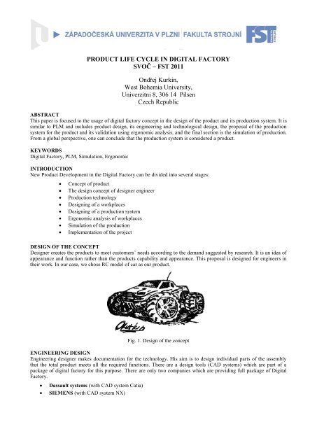
Designer creates the products to meet customers’ needs according to the demand suggested by research. It is an idea of<br />
appearance and function rather than the products capability and appearance. This proposal is designed for engineers in<br />
their work. In our case, we chose RC model of car as our product.<br />
Fig. 1. Design of the concept<br />
ENGINEERING DESIGN<br />
Engineering designer makes documentation for the technology. His aim is to design individual parts of the assembly<br />
that the total product meets all the required functions. There are a design tools (CAD systems) which are part of a<br />
package of digital factory for this purpose. There are only two companies which are providing full package of Digital<br />
Factory.<br />
<br />
<br />
Dassault systems (with CAD system Catia)<br />
SIEMENS (with CAD system NX)
These engineering tools allows designer to:<br />
Design of individual components of the product<br />
Static and dynamic analysis<br />
Virtual simulation and report completion of its functionality<br />
Creation of technical documentation for technology<br />
In our case, we chose a suspension arm for the stress analysis and analysis of the technology.<br />
Fig. 2. Examples of work in design tool NX<br />
TECHNOLOGICAL SOLUTIONS<br />
After that the designer creates drawings, process engineer begins with designing of the manufacturing process for<br />
individual components and their subsequent assembly into a complete assembly. The manufacturing process means:<br />
<br />
<br />
<br />
Choosing of working machines and tools for the production of individual components<br />
Determination of working conditions<br />
Generation of CNC programs (if there are used CNC machines in the production)<br />
We can use of technological modules which are parts of the CAD systems (CATIA and NX). These modules allow<br />
engineers to virtually simulate a manufacturing process. Technologist can choose:<br />
<br />
<br />
<br />
<br />
Method of machining<br />
Cutting machining conditions<br />
The control system of CNC machine<br />
Analyze a precision after machining<br />
On Fig.3 you can see a design of injection head for production suspension. There is example of machining of the main<br />
board of the injection head. When control system is defined (in our case SINUMERINK) technologist can simulate a<br />
progress of machining. It can simulate only a cutting tool or whole machine. The biggest advantage of this<br />
technological module (in case of NX) is that we can simulate that the machine runs directly according to the CNC<br />
program. In many other technological tools, the simulation is run only by the CL data, which are not gone through the<br />
post-processor.<br />
Injection Head<br />
Simulating of the<br />
cutting tool<br />
Simulating of the<br />
machine<br />
Analysis of a precision<br />
after machining<br />
Generated NC<br />
program<br />
Fig. 3. Examples of technological operations in NX
DEFINING OF THE PRODUCTION PROCESS<br />
When technology is ready for production, according type of a production industrial engineer has to design production<br />
process. Industrial engineer has to:<br />
<br />
<br />
<br />
<br />
<br />
<br />
Design a production processes<br />
Set the tact of the production line<br />
Design a individual workplaces<br />
Design a manufacturing system<br />
Design a supplies<br />
Ergonomic analysis of workers<br />
We will use package digital factory for this purposes again. In our case, the production system is modeled in product<br />
Tecnomatix.<br />
Design of the processes is divided to several steps:<br />
<br />
<br />
<br />
<br />
<br />
Rough planning<br />
Fine planning<br />
Simulation and verification of the fine planning<br />
Ergonomic analysis of the workplaces<br />
Discrete event simulations of the manufacturing system<br />
ROUGH PLANNING<br />
There are defined resources, products and processes of individual operations in rough planning. We use the Process<br />
Designer for these tasks.<br />
Resources<br />
Resources encompass everything needed to ensure the process eg workbench, tools and workers themselves. The Fig.4<br />
shows the layout of resources.<br />
Fig. 4. layout of resources for production of RC car<br />
Products<br />
Products are components of the input and output sub-assemblies of components or assemblies. In our case, Products are<br />
parts of a RC car. On Fig.5 You can see tree of parts and assemblies of our mode<br />
Part of RC car<br />
Fig. 5. Product tree<br />
Product tree
Process<br />
The process changes inputs to outputs using resources. We split an operation to sub-operations in rough planning eg:<br />
vice a part to mounting device or move the box with the material. The big advantage of the Process Designer, are time<br />
tables with the MTM codes. You can simply define an operation eg: fixing a part to mounting device and Process<br />
Designer automatically calculates according a MTM codes operation times.<br />
FINE PLANNING<br />
Process Simulate serves to verify of assigned times from Process Designer. Process Simulate is a simulation tool for<br />
real simulations such as human motion in the assembly operations. Operations are defined to the sub-tasks such as<br />
finger grips for gripping parts, etc. After running the simulation, we have a new (simulated) times of operations. This<br />
new times will be compared with times from Process Designer. We can decide which time we will use in project.<br />
The Fig.6 shows the difference in the times from Process Designer and Process Simulate. Process Simulate is also used<br />
for verifying collisions in automated robotic manufacturing. Simulations of robot motions can help with organizing of<br />
workplaces. On Fig.6 the lower picture shows more detailed planning of operations. There you can see a difference in<br />
time of first sub-operation. Difference in time is 0.3 seconds compared to rough planning<br />
Fig. 6. Rough and Fine Planning<br />
ERGONOMIC ANALYSIS<br />
We are testing an individual workplace after defining the operations, resources and products. There is a ergonomic tool<br />
JACK for this tasks. This tool contains a realistic model of a man with ties to the bones, muscles, joints, etc. You can<br />
set a male of human, weight, height. All these proportions affect a human at work.<br />
According to the results of each analysis, it is necessary to modify the workplace for the worker. After this we can again<br />
simulate a production process in Process Simulate. This cycle is repeated until we achieve the best results.<br />
Fig. 7. Ergonomic tool JACK
DISCRETE EVENT SIMULATION<br />
The last part of the package of Digital Factory is a simulation tool Plant Simulation for discrete simulations of<br />
manufacturing processes. After ergonomic analysis in JACK, we can export a data from Process Designer to Plant<br />
Simulation. We can simulate different situations which can occur in production process. We can define cost time,<br />
number of scrap, machine failures, etc. and in the report we can see eg costs per period, investment per period number<br />
scrap etc.<br />
Fig. 8. Discrete event simulation, in Plant simulation 9<br />
CONCLUSION<br />
In today's globalized era, Ahead of the competition means a distinct advantage in the market in today's globalized era.<br />
Every investment should be very well considered. The biggest advantage of the Digital Factory is that everything<br />
happens in the virtual world. It is possible to test numerous scenarios and problems that might arise in real business.<br />
When a problem occurs in the virtual model is not difficult to remove it, but in real company are these solutions of any<br />
problems very expensive. Another big advantage is the data consistency. We have a data format which can work with<br />
all of the tools of the package.<br />
The cost of the digital factory is only the cost of time spent preparing the virtual model and the cost of software. Each<br />
enterprise must consider whether it is advantageous to him the whole package or just some debris from the instruments.<br />
In our example is shown in virtually all life-cycle of the product to distribution of the product (not included here to<br />
return the product). Each tool can be used separately.<br />
ACKNOWLEDGMENT<br />
This paper was created with the subsidy of the project 402/08/H051 under the Grant Academy of the Czech Republic.<br />
The name of this project is “Optimization of multidisciplinary design and modelling of virtual firm’s production<br />
systems”.<br />
REFERENCES<br />
[1] TUPA, J.; KAŠPAR, P.; BASL, J. Process Performance Management Application for Technological Process Control. In<br />
Proceedings of the 17th International Conference on Flexible Automation and Intelligent Manufacturing. Beijing : Hongde<br />
Tongda, 2007. s. 460-467. ISBN 978-1-4276-2092-7<br />
[2] VOTAVA, V. – ULRYCH, Z. – EDL, M. - KORECKÝ, M. – TRKOVSKÝ, V. Analysis and Optimization of Complex Small -<br />
Lot Production in New Manufacturing Facilities Based on Discrete Simulation. In: 20th European Modeling & Simulation<br />
Symposium (EMSS 2008), Campora San Giovanni, Amantea (CS), Italy, September 17-19, 2008. ISBN 978-88-903724-0-7.<br />
[3] Saaty L. T. & Vargas G. L. (2006). Decision making with the analytic network process: economic, political, social<br />
and technological applications with benefits, opportunities costs and risks, Springer Science + Business Media,<br />
LLC, ISBN 978-0387-33859-0, New York, USA<br />
[4] Internal materials and manuals from SIEMNS PLM Software<br />
[5] BANKS, J., CARSON, S J., NELSON L B., NICOL, M D. (2005) Discrete-Event System Simulation, Pearson Prentice Hall,<br />
New Jersey ISBN 0-13-088702-1<br />
[6] Votava, Václav. Simulace ve strojírenství. 1. vyd. Plzeň : Západočeská <strong>univerzita</strong>, 2008. ISBN 978-80-7043-659-2.<br />
[7] ŠIMON, M. and ČERNÝ, Z.(2009): Strategic planning of joint logistics at the level of horizontal cooperation, In Annals of<br />
DAAAM for 2009 & Proceedings of the 20th international DAAAM symposium, 2009, str. 657-658, ISBN 978-3-901509-70-4<br />
[8] Internal materials and manuals from SIEMNS PLM Software