LPOD KuBand Block up Converter SSPA - Sematron UK Ltd.
LPOD KuBand Block up Converter SSPA - Sematron UK Ltd.
LPOD KuBand Block up Converter SSPA - Sematron UK Ltd.

Create successful ePaper yourself
Turn your PDF publications into a flip-book with our unique Google optimized e-Paper software.
Datasheet<br />
Rev A. Mar 09.<br />
<strong>LPOD</strong> C- or Ku-Band<br />
<strong>Block</strong> Up <strong>Converter</strong> (BUC)/<strong>SSPA</strong><br />
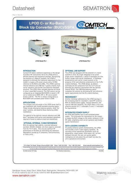
<strong>LPOD</strong> Model PS-1<br />
<strong>LPOD</strong> Model PS-2<br />
INTRODUCTION<br />
Comtech EF Data’s extensive experience in the design<br />
of outdoor RF transceivers led to the <strong>LPOD</strong> family’s<br />
efficient thermal and mechanical package. Recognizing<br />
the evolution of L-Band IF systems, the <strong>LPOD</strong> is<br />
designed to eliminate the traditional requirement for the<br />
modem to s<strong>up</strong>ply a DC power source and a 10 MHz<br />
reference to the BUCs and LNBs. The <strong>LPOD</strong>’s optional<br />
internal reference and LNB bias T greatly simplify multicarrier<br />
operation and provide cost-effective redundant<br />
solutions. The <strong>LPOD</strong> offers valuable features not found<br />
in other L-band BUC products. The PS2 version can be<br />
configured as an integrated BUC/<strong>SSPA</strong> (L-band in, RF<br />
out) or solely as an <strong>SSPA</strong> (RF in, RF out) at power<br />
levels to 250 W. The PS1 is always configured as a<br />
BUC/<strong>SSPA</strong> with available power levels to 50W.<br />
APPLICATIONS<br />
The compact size and weight of the <strong>LPOD</strong> lends itself to<br />
any installation with limited available mounting space.<br />
These include ship-borne antenna systems, small “flyaway”<br />
systems, and Satellite News Gathering (SNG)<br />
installations.<br />
The addition of the optional internal reference and LNB<br />
bias T facilitates multi-carrier and redundant operations<br />
required of small-to medium-sized hub installations.<br />
OPTIONAL INTERNAL 10 MHZ REFERENCE<br />
With the optional high stability, ovenized reference<br />
oscillator (OCXO) installed, one more signal is removed<br />
from the TX IF cable. This ensures optimum RF<br />
performance of the BUC by eliminating any reference<br />
degradation caused by IF combiners, interconnections,<br />
or rotary joints.<br />
OPTIONAL LNB SUPPORT<br />
The <strong>LPOD</strong> was designed with the evolution of L-band<br />
systems in mind. No longer relegated to low power<br />
single carrier installations, L-band IF topologies are now<br />
found in larger multi-carrier installations. A challenge<br />
presented by multi-carrier L-band systems is the<br />
presence of DC and reference components on the Tx/Rx<br />
L-band interfaces. The <strong>LPOD</strong> design, by default,<br />
eliminates the DC component from the Tx IF and can<br />
eliminate the reference requirement with the optional<br />
internal OCXO. The LNB bias/reference option<br />
completes the solution by eliminating DC and reference<br />
signal requirements from the Rx L-band interface.<br />
REDUNDANCY<br />
Another challenge addressed by the <strong>LPOD</strong> topology is<br />
the increasing need for redundant L-band RF solutions.<br />
With its internal power s<strong>up</strong>ply, internal reference, and<br />
internal LNB bias capability, the <strong>LPOD</strong> offers a very cost<br />
effective solution for 1:1 redundant Tx and 1:1 redundant<br />
Rx requirements.<br />
INTEGRATED POWER SUPPLY<br />
All <strong>LPOD</strong> BUC/<strong>SSPA</strong>s have a self-contained power<br />
s<strong>up</strong>ply. This eliminates the requirement for the modem<br />
to s<strong>up</strong>ply the BUC voltage on the center conductor of the<br />
RF cable, simplifying multi-carrier operation and modem<br />
spares maintenance.<br />
DATA LOGGING CAPABILITY<br />
To greatly enhance system maintainability, the <strong>LPOD</strong><br />
line includes a built in data logging capability. By<br />
recording critical operational parameters (such as<br />
temperature, output power, mute status, etc.) at time<br />
stamped intervals, the user can quickly gather<br />
intelligence not only about the unit itself, but also the<br />
unit’s operational environment.<br />
Amplifiers<br />
2114 West 7th Street, Tempe, Arizona 85281 USA Voice 1 480 333 2200 Fax 1 480 333 2540 Email sales@comtechefdata.com<br />
Comtech EF Data reserves the right to change specifications of products described in this document at any time without notice and without obligation to notify any person of such changes. Information in this<br />
document may differ from that published in other Comtech EF Data documents. Refer to the website or contact Customer Service for the latest released product information.<br />
© 2008 Comtech EF Data Part Number ds-lpod.docx 9/9/2008<br />
Sandpiper House, Aviary Court, Wade Road, Basingstoke, Hampshire, RG24 8GX, <strong>UK</strong><br />
T +44 (0) 1256 812 222 F +44 (0) 1256 812 666 E sales@sematron.com<br />
www.sematron.com<br />
Making waves...
Datasheet<br />
<strong>LPOD</strong> C- or Ku-Band <strong>Block</strong> Up <strong>Converter</strong> (BUC)/<strong>SSPA</strong><br />
CHARACTERISTICS<br />
IF Input Frequency Note 1<br />
RF Output Frequency<br />
950 – 1525 MHz 5.850 – 6.425 GHz<br />
950 – 1750 MHz 5.850 – 6.650 GHz (optional)<br />
950 – 1825 MHz 5.850 – 6.725 GHz (optional)<br />
950 – 1450 MHz 14.00 – 14.50 GHz<br />
950 – 1750 MHz 13.75 – 14.50 GHz (optional)<br />
Data Logging parameters<br />
Non-Volatile RAM : Capacity 30 days<br />
@ 90 minute intervals.<br />
Includes:<br />
RF Output Power<br />
Mute Status<br />
Heatsink Temperature<br />
LNB Bias Current<br />
Model Psat (Typical) P1dB<br />
(Guaranteed) Note 2<br />
Gain Min<br />
(Typical)<br />
PS1-20Ku 43 dBm (20W) 42 dBm (16W) 70 (75dB)<br />
PS1-32Ku 45 dBm (32W) 44 dBm (25W) 70 (75dB)<br />
PS1-32C 45 dBm (32W) 44 dBm (25W) 70 (75dB)<br />
PS1-50C 47 dBm (50W) 46 dBm (40W) 70 (75dB)<br />
PS2-125C 51 dBm (125W) 50 dBm (100W) 70 (75dB)<br />
PS2-150C 52 dBm (150W) 51 dBm (125W) 70 (75dB)<br />
PS2-200C 53 dBm (200W) 52.5 dBm (175W) 70 (75dB)<br />
PS2-250C 54 dBm (250W) 53 dBm (200W) 70 (75dB)<br />
Input Power S<strong>up</strong>ply Requirements: 90 – 264 VAC, 47-63 Hz, Power<br />
Factor Corrected, .96 (48 VDC optional)<br />
Model P typical, W P max, W<br />
PS1-20Ku 200 W 210 W<br />
PS1-32Ku 220 W 260 W<br />
PS1-25C 200 W 220 W<br />
PS1-50C 270 W 300 W<br />
PS2-125C 750 W 950 W<br />
PS2-150C 800 W 1000 W<br />
PS2-200C 950 W 1400 W<br />
PS2-250C 1000 W 1500 W<br />
Max IF Input level (no damage ) +10 dBm<br />
Gain Adjust<br />
20 dB in 0.25 dB steps<br />
Gain Flatness<br />
± 1.5 dB full band (± 1.0 dB PS2<br />
configured as <strong>SSPA</strong> only)<br />
± 0.30 dB per 40 MHz<br />
Gain variation over temp ±1.5 dB max, -40 to +55 °C<br />
Input Return Loss<br />
15 dB (19.1 dB PS2 configured as<br />
<strong>SSPA</strong> only)<br />
Output Return Loss<br />
19.1 dB (1.25:1 VSWR)<br />
Noise Figure<br />
10-15 dB typ, 20 dB max @ min.<br />
attenuation, (8 dB typ, 15 dB max<br />
PS2 configured as <strong>SSPA</strong> only)<br />
RF Mute Isolation<br />
-60 dBc min<br />
AM/PM Conversion<br />
2° typ., 3.5° max. @ Rated P1dB<br />
3rd Order Intermod. Level<br />
-30 dBc typ., -25 dBc Guaranteed<br />
(2 tones, @ -3 dB Total Back Off<br />
from P1 dB (-6 dBc SCL), 1<br />
MHz)<br />
Spurious Level<br />
Harmonics<br />
-50 dBc @ Prated - 3dB<br />
Carrier Related In Band<br />
-60 dBc min. @ P1dB<br />
Non-Carrier Related In Band -60 dBm max.( Input Terminated)<br />
LO Leakage<br />
-25 dBm max. ( Input Terminated)<br />
Linear ± 0.03ns/MHz<br />
Gro<strong>up</strong> delay variation<br />
Parabolic ± .003ns/MHz2<br />
Ripple ± 1.0 ns pk-pk<br />
Notes:<br />
1. PS2 Models available as <strong>SSPA</strong>s only, without internal L-<br />
band BUC (Freq RF in = Freq RF out)<br />
2. Allow 1 dB degradation from 13.75 to 14.0 GHz and 6425 to 6725 MHz<br />
Phase Noise (dBc/Hz) (with<br />
optional internal or<br />
equivalent performance<br />
external reference)<br />
Typical<br />
(C/Ku)<br />
dBc/Hz<br />
Spec<br />
(C/Ku)<br />
dBc/Hz<br />
Offset = 100 Hz -79/-76 -72/-69<br />
1 KHz -91/-89 -84/-82<br />
10 KHz -105/-98 -97/-90<br />
100 KHz -120/-115 -107/-102<br />
1 MHz -132/-132 -115/-115<br />
OPTIONAL INTERNAL REFERENCE<br />
Internal Reference Oscillator<br />
Frequency<br />
Frequency Stability<br />
OPTIONAL LNB BIAS/REFERENCE<br />
LNB Bias Voltage<br />
LNB 10 MHz Reference Output<br />
Level<br />
LNB Input/Output Return Loss<br />
LNB Input/Output Gain<br />
LNB Input/Output Gain Flatness<br />
LNB input/Output Isolation (Mute<br />
condition)<br />
ENVIRONMENTAL<br />
Temperature<br />
Operating<br />
Storage<br />
Humidity<br />
Altitude<br />
Shock<br />
10 MHz(Can lock to modem s<strong>up</strong>plied<br />
reference over a range of -5 dBm to<br />
+5 dBm at IF Input)<br />
5 x 10 –10 / day<br />
1 x 10 -8 ( -40º to +55ºC)<br />
22 ±1V @ 450mA max<br />
0 dBm ±5dB<br />
15 dB<br />
10 dB ± 2 dB (950-1750 MHz)<br />
-1 dB ± 2 dB (optional)<br />
± 1 dB (950-1750 MHz)<br />
55 dB min<br />
-40º to 122ºF (-40º to 55ºC) (optional to +60ºC)<br />
-67º to 167ºF (-55º to 75ºC)<br />
100% condensing rain 2” per hour<br />
10,000 AMSL<br />
Normal commercial shipping and handling<br />
PHYSICAL<br />
Weight / Dimensions(inches excluding connectors)<br />
PS1 17 lbs. Nominal / 12.65 X 6.26 X7.37<br />
PS2 47 lbs Nominal / 8.80 X 9.78 X 16.81<br />
Connectors<br />
IF/RF Input Type N, female<br />
RF Output PS1/PS2 Ku Band: WR75G<br />
PS1, C-band: Type N, female<br />
PS2, C-band: CPR137G<br />
LNB Bias<br />
Type N, female<br />
M&C/Ethernet/<br />
Redundancy<br />
Switches<br />
19 pin MS Style (Single Integrated cable assembly<br />
available, dependent <strong>up</strong>on configuration)<br />
Advanced Communication Solutions<br />
www.comtechefdata.com<br />
Sandpiper House, Aviary Court, Wade Road, Basingstoke, Hampshire, RG24 8GX, <strong>UK</strong><br />
T +44 (0) 1256 812 222 F +44 (0) 1256 812 666 E sales@sematron.com<br />
www.sematron.com<br />
Making waves...