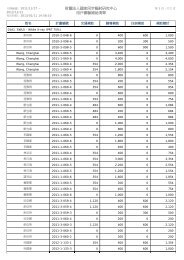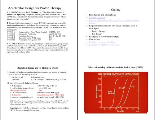
Accelerator Design for Proton Therapy
Accelerator Design for Proton Therapy
Accelerator Design for Proton Therapy

Create successful ePaper yourself
Turn your PDF publications into a flip-book with our unique Google optimized e-Paper software.
<strong>Accelerator</strong> <strong>Design</strong> <strong>for</strong> <strong>Proton</strong> <strong>Therapy</strong><br />
1. In 1998 OCPA school, Profs. Yuzheng Lin (Tsing-Hua Univ, China) and<br />
Frank K.H. Ngo (Yang-Ming Univ, Taiwan) gave three excellent LECTURES<br />
on “Medical applications”, “Radiation treatment programs in Taiwan.” These<br />
lecture notes are very useful!<br />
2. The particle therapy cooperative group (PTCOG) organizes yearly scientific<br />
meetings and educational workshops. Recent progresses on treatment protocol<br />
and technology are presented in the workshop. The Past and Scheduled PTCOG<br />
meetings are:<br />
PTCOG 46 Shandong, Zibo, China (Wanjie Hospital) 18-23 May 2007<br />
PTCOG 47 Jacksonville, Florida, USA May 19 - 24, 2008<br />
PTCOG 48 Heidelberg, Germany Sept. 29 - Oct. 03, 2009<br />
PTCOG 49 Gunma University - NIRS, Japan 2010<br />
PTCOG 50 Philadelphia, Pennsylvania, USA 2011<br />
3. The PIMMS (<strong>Proton</strong>-Ion Medical Machine Study), a collaborative study group between<br />
CERN, GSI (Germany), Med-AUSTRON (Austria), TERA (Italy) and Oncology 2000<br />
(Czech Republic), published CERN yellow reports that aimed <strong>for</strong> a “best” possible design<br />
<strong>for</strong> a synchrotron-based medical treatment facility delivering protons and carbon ions. The<br />
reports are freely available online.<br />
Outline<br />
• Introduction and Motivations:<br />
• Cancer statistics<br />
• Physics of Radiation therapy, X-ray, proton and ion<br />
therapy<br />
• Requirement and review of various concepts, tools &<br />
techniques<br />
– <strong>Proton</strong> therapy<br />
– Ion therapy<br />
• Examples of <strong>Accelerator</strong> designs<br />
• Conclusions<br />
• Cancer treatment facilities<br />
• Example of MPRI construction<br />
Radiation dosage and its Biological effects<br />
I. Activity: it defined d as the number of radioactive decay per second of a sample.<br />
Since dN/dt=−λN, the activity is A=λN.<br />
1 Bq (becquerel) 1 disintegration/s<br />
1Ci( (curie) 37 3.7×10 10 decays/s ~ the activity i of f1g of 226 Ra.<br />
II. Unit of (Absorbed) Radiation Dosage<br />
1 R (Roentgen) 2.58×10 −4 C/kg of dry air<br />
1 rad (radiation absorbed dose) 1 erg/g=0.01 J/kg<br />
1Gy (gray) =100 rad<br />
1 J/kg<br />
1 DE (dose effective) (absorbed dose)×RBE (QF)<br />
1 Sv (sievert) (absorbed dose in Gy) ×RBE (QF)<br />
1 rem (rad equivalent in man) (absorbed dose in rad) ×RBE (QF)<br />
CGE=Cobalt Gray Equivalent; organ at risk (OAR); gross tumor volume (GTV); CTV (clinical<br />
target volume) = GTV + 5-10 mm; planned treatment volume PTV = CTV + 5~10 mm; dose<br />
volume histograms (DVH)<br />
Effects of ionizing radiations and the Lethal Dose (LD50)<br />
10 mGy to bone marrow risk of leukemia = 2/100,000000<br />
0.1 Gy whole body no detectable effects<br />
elevated chromosome aberrations<br />
0.25-0.5 0.5 Gy detectable change in number of cells<br />
1 Gy mild radiation sickness, nausea, fatigue<br />
4 Gy death likely <strong>for</strong> 50%<br />
6-9 Gy eye cataract<br />
10 Gy skin erythema and blistering<br />
20-50 Gy intestinal track damage<br />
>100 Gy central nervous system damage; death in<br />
48 hours<br />
Stopping power (-dE/dx) is the energy lost by a charged particle in a medium.<br />
LET is the energy absorbed in the target.
RBE =<br />
D x<br />
D 0<br />
Biological Effect (RBE) vs LET<br />
Radiation<br />
i Typical LET values<br />
1.2 MeV 60 Co gamma 0.3 keV/µm<br />
250 kVp x rays 2 keV/µm<br />
10 MeV protons 47k 4.7 keV/µm<br />
150 MeV protons 0.5 keV/µm<br />
14 MeV neutrons 12 keV/µm<br />
Heavy charged particles<br />
100-2000 keV/µm<br />
2.5 MeV alpha particles 166 keV/µm<br />
2 GeV Fe ions 1,000 keV/µm<br />
•Oxygen Effect<br />
– The OER typically ranges<br />
between values of 2.5-3.0.<br />
– Half maximal sensitivity occurs<br />
at oxygen tensions of ~ 3 mm<br />
Hg.<br />
– Above pO 2 values of ~ 20 mm<br />
Hg near maximal oxygen<br />
effects are seen.<br />
OER and RBE vs LET
Main Specifications of a <strong>Proton</strong> <strong>Therapy</strong> System<br />
• Ability to reach the tumor<br />
Range in patient: up to 32 g/cm²<br />
Range modulation: up to full range, with steps of 0.5 g/cm²<br />
Field size: up to 30 x 40 cm<br />
• Ability to reach the tumor in a supine patient from any selected direction<br />
Isocentric Gantry<br />
Precise, robotic patient positioning<br />
Selection of Nozzles<br />
In fact, Monte Carlo simulations show<br />
that 3 intensity modulated fixed beams<br />
can effectively and properly simulate<br />
gantry target volume.<br />
• Ability to reach the tumor accurately<br />
Penumbra: maximum 2 mm at skin<br />
Distal dose falloff: maximum 1 mm above physical py limit<br />
Patient position accuracy and reproducibility: 0.5 mm <strong>for</strong> small displacements<br />
Gantry accuracy and reproducibility: 1 mm radius circle of confusion<br />
Alignment methods: orthogonal Digital Radiography System (DRS), lasers etc.<br />
• Ability to control and verify the dose deposition<br />
Energy: To reach 30 cm in tissue,<br />
p C 12<br />
protons ~250 MeV (Brho~2.5 Tm),<br />
E/u (MeV) 250 400<br />
carbon ~ 400 MeV/u (Brho~6.5 Tm). Brho (T‐m) 2.43 6.35<br />
LET (RBE and OER)<br />
L_dip (m) 11 29<br />
Intensity: To treat a 20 x 20 x 10 cm volume in under 1 minute to 2 Gy:<br />
proton >1 x10 10 per second,<br />
carbon > 3 x 10 8 per second delivered to the treatment field.<br />
As overall efficiencies in beam utilization can be as low as 10%, accelerator<br />
capability should be about 10 times higher. The inefficiencies arises either from<br />
absorption and collimation in passive scattering systems; from reductions in<br />
intensity to minimize effect of spikes in a noisy spill, or from various gating<br />
scenarios to compensate <strong>for</strong> patient motion.<br />
Safety: Redundancy of dosimetry and control systems, and an extremely welltrained<br />
and constantly alert staff are mandatory. The technical per<strong>for</strong>mance and<br />
psychological lintensity i levels l are greater than experienced at most accelerator<br />
facilities, and require particular attention in facility designs.<br />
Availability: An accelerator system operating in a clinical environment must have<br />
reliability > 95%. 15~30 minutes/fraction; 8/16-hour treatment days, 6 days per<br />
week; 50 weeks per year. In addition, time <strong>for</strong> beam calibrations and QA checks.<br />
2<br />
z<br />
KE [MeV/u] ≈150<br />
+ 85<br />
A<br />
<strong>for</strong> a range of 30 cm in water
Clinical considerations on facility design<br />
• The most important elements defining i the system per<strong>for</strong>mance<br />
are the Nozzle, the Patient Positioning system and the beam<br />
delivery system!<br />
• The <strong>Accelerator</strong> and the Beam Transport System have much<br />
less impact on the system per<strong>for</strong>mance!<br />
• ELISA (Energy, LET, Intensity, Safety, Availability)<br />
• The simplest accelerator meeting the clinical specifications in<br />
a cost-effective way should be selected! The <strong>Accelerator</strong> should<br />
be transparent at treatment level. Examples of accelerator<br />
design will be given below<br />
Beam requirements and accelerator choices<br />
Energy<br />
Energy<br />
Beam<br />
Beam<br />
Fast beam<br />
(MeV/u) stability Intensity current current<br />
<strong>Proton</strong> 250 ∆E/E <strong>for</strong> ≥5×10 10 pps Stability <strong>for</strong> control <strong>for</strong><br />
distal<br />
wobbling & con<strong>for</strong>mal<br />
Ions (C12) 400 control ≥5×10 8 pps scanning therapy<br />
Linac Cyclotron FFAG Synchrotron DWA<br />
B-field none constant constant varying none<br />
F_rf constant constant varying varying pulsed<br />
E_Change degrader degrader Acc. cycle Acc. cycle Pulse by pulse<br />
Current (nA) 1600 1~100 1~100 1~10 Very high<br />
Rep rate (Hz) 1~60 continuous 100~10001000 05 0.5~5050 100 pi-mm-mrad<br />
N B ~ 3×10 10 to 1×10 11<br />
B<br />
Multi-turn injection simulation
Septum separation<br />
Injection beam clears from main dipoles<br />
Enough space <strong>for</strong> stripping foil assemply<br />
Using the 7 MeV/u linac or the 6 MeV/u FFAG C 4+ sources, we<br />
can easily accumulate a beam of 10 11 C 6+ with an emittance of<br />
17 π-mm-mrad in the synchrotron.<br />
Space charge limit:<br />
p C 12<br />
A 1 12<br />
Z 1 6<br />
Circum(m) 30 65<br />
Einj/u (MeV) 7 7<br />
Eext/u (MeV) 250 400<br />
p (MeV/c)/u 729.13 951.42<br />
Brho (T‐m) 2.43 6.35<br />
dnu_sc 0.2 0.2<br />
N_sc 1.01E+11 3.38E+10<br />
epsN (μm) 2 2<br />
beta_inj 0.12 0.12<br />
gamma_inj 1.0075 1.0075<br />
Example: Characteristics of HIMAC<br />
1984: Governmental 10 years strategy <strong>for</strong> cancer control<br />
1993: Construction of heavy ion medical accelerator in Chiba(HIMAC)<br />
ions<br />
He to Ar<br />
E_max (MeV/u) 800<br />
Minimum Energy (MeV/u) 100<br />
Beam Intensity<br />
He: 12×10 1.2×10 10 pps<br />
C: 2×10 9 pps<br />
Ar: 2.7×10 8 pps<br />
Treatment Characteristics<br />
Field size 22 cm<br />
Beam homogeneity ±2%<br />
Maximum range 30 cm<br />
Dose rate 5 Gy/min.<br />
Treatment rooms 3 (A,B,C)<br />
Other instabilities?
Extraction:<br />
•Fast extraction<br />
•slow extraction<br />
CIS: Circumference = 1/5 C_cooler = 17.364 m<br />
Dipole length = 2 m, 90 degree bend, edge angle = 12 deg.<br />
Inj KE= 7 MeV, extraction: ti 250 MeV<br />
0.5 to 10 sec<br />
250 MeV <strong>Proton</strong> Synchrotron<br />
1996-1999<br />
Example: a Compact medical proton Synchrotron Ldip=3.0 m<br />
ρ=1.91 m<br />
Edge_angle=8.5°<br />
5m<br />
Circum=28.5 m<br />
Qx=1.68<br />
Qz=0.71<br />
KE_tr=356 MeV<br />
Ldip=3.0 m<br />
ρ=1.91 m<br />
Edge_angle=8.5°<br />
Circum=28.5 m<br />
Qx=1.68<br />
Qz=0.71<br />
KE_tr=356 MeV<br />
3.25m
Hitachi Medical Synchrotron<br />
Dynamical Aperture<br />
RCS, S. Peggs, et al
PIMMS<br />
C (m) 75.2<br />
E_inj (MeV)/u 7<br />
E_max(MeV)/u 400<br />
Dipole length (m) 1.553<br />
Dipole number 16<br />
Edge angle (deg)<br />
Quad (iron core) 24<br />
Quad (air core)<br />
sextupole 5<br />
Qx 1.8<br />
Qy 1.85<br />
A preliminary design of a heavy ion therapy synchrotron<br />
SY S.Y. LeeandW W. Tam<br />
A preliminary design of a carbon ion<br />
synchrotron that can accelerate C 6+ ions<br />
from around 6~7 MeV/u to 400 MeV/u.<br />
The lattice function, the betatron<br />
tunes and local closed orbit bump<br />
<strong>for</strong> two injection kickers are<br />
shown. Note that a trim quad will<br />
be used to move the betatron tune<br />
<strong>for</strong> the 3 rd resonance slow<br />
extraction.<br />
Conclusions<br />
• Clinical experiences show that the Hadron therapy has advantage over<br />
the photon therapy on cancer control. The number of hadron facilities is<br />
expanding rapidly worldwide.<br />
• Two most common accelerator designs are synchrotron and cyclotron.<br />
Both systems work! A “technical” community exist! A full set of high<br />
tech applications <strong>for</strong> physicists & engineers who can interact with medical<br />
doctors! Medical physicists are well paid and in high demand. Dose<br />
verifiability, Beam Stability, Reliability and Reproducibility are utmost<br />
important in a radiation therapy facility.<br />
• Applications of accelerator, Nuclear and HEP experiences<br />
– Better resolution and faster detectors<br />
– Fast and compact electronics<br />
– Better and reliable beam control systems<br />
– Online controls, monitoring and fast Data Acquisition<br />
– New “in situ” imaging and dose verification technologies (in beam PET..)<br />
– Simulation & modeling <strong>for</strong> treatment planning<br />
• Example of MPRI construction