rectangular microstrip patch antenna loaded with ... - ijater
rectangular microstrip patch antenna loaded with ... - ijater
rectangular microstrip patch antenna loaded with ... - ijater

Create successful ePaper yourself
Turn your PDF publications into a flip-book with our unique Google optimized e-Paper software.
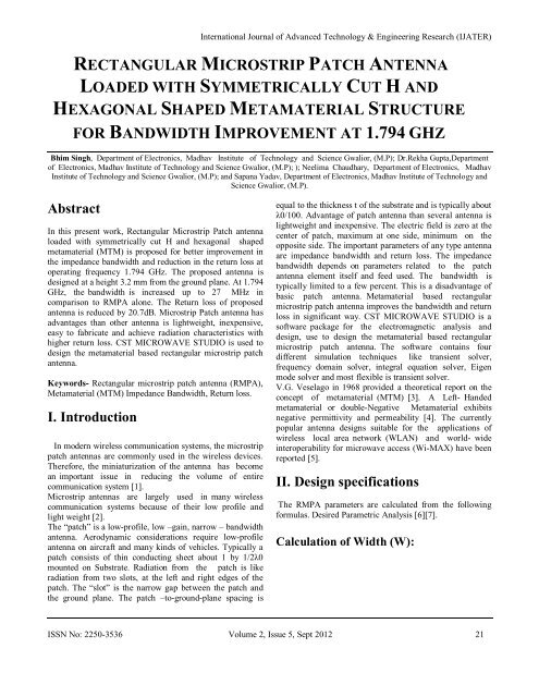
International Journal of Advanced Technology & Engineering Research (IJATER)<br />
RECTANGULAR MICROSTRIP PATCH ANTENNA<br />
LOADED WITH SYMMETRICALLY CUT H AND<br />
HEXAGONAL SHAPED METAMATERIAL STRUCTURE<br />
FOR BANDWIDTH IMPROVEMENT AT 1.794 GHZ<br />
Bhim Singh, Department of Electronics, Madhav Institute of Technology and Science Gwalior, (M.P); Dr.Rekha Gupta,Department<br />
of Electronics, Madhav Institute of Technology and Science Gwalior, (M.P); ); Neelima Chaudhary, Department of Electronics, Madhav<br />
Institute of Technology and Science Gwalior, (M.P); and Sapana Yadav, Department of Electronics, Madhav Institute of Technology and<br />
Science Gwalior, (M.P).<br />
Abstract<br />
In this present work, Rectangular Microstrip Patch <strong>antenna</strong><br />
<strong>loaded</strong> <strong>with</strong> symmetrically cut H and hexagonal shaped<br />
metamaterial (MTM) is proposed for better improvement in<br />
the impedance bandwidth and reduction in the return loss at<br />
operating frequency 1.794 GHz. The proposed <strong>antenna</strong> is<br />
designed at a height 3.2 mm from the ground plane. At 1.794<br />
GHz, the bandwidth is increased up to 27 MHz in<br />
comparison to RMPA alone. The Return loss of proposed<br />
<strong>antenna</strong> is reduced by 20.7dB. Microstrip Patch <strong>antenna</strong> has<br />
advantages than other <strong>antenna</strong> is lightweight, inexpensive,<br />
easy to fabricate and achieve radiation characteristics <strong>with</strong><br />
higher return loss. CST MICROWAVE STUDIO is used to<br />
design the metamaterial based <strong>rectangular</strong> <strong>microstrip</strong> <strong>patch</strong><br />
<strong>antenna</strong>.<br />
Keywords- Rectangular <strong>microstrip</strong> <strong>patch</strong> <strong>antenna</strong> (RMPA),<br />
Metamaterial (MTM) Impedance Bandwidth, Return loss.<br />
I. Introduction<br />
In modern wireless communication systems, the <strong>microstrip</strong><br />
<strong>patch</strong> <strong>antenna</strong>s are commonly used in the wireless devices.<br />
Therefore, the miniaturization of the <strong>antenna</strong> has become<br />
an important issue in reducing the volume of entire<br />
communication system [1].<br />
Microstrip <strong>antenna</strong>s are largely used in many wireless<br />
communication systems because of their low profile and<br />
light weight [2].<br />
The “<strong>patch</strong>” is a low-profile, low –gain, narrow – bandwidth<br />
<strong>antenna</strong>. Aerodynamic considerations require low-profile<br />
<strong>antenna</strong> on aircraft and many kinds of vehicles. Typically a<br />
<strong>patch</strong> consists of thin conducting sheet about 1 by 1/2λ0<br />
mounted on Substrate. Radiation from the <strong>patch</strong> is like<br />
radiation from two slots, at the left and right edges of the<br />
<strong>patch</strong>. The “slot” is the narrow gap between the <strong>patch</strong> and<br />
the ground plane. The <strong>patch</strong> –to-ground-plane spacing is<br />
equal to the thickness t of the substrate and is typically about<br />
λ0/100. Advantage of <strong>patch</strong> <strong>antenna</strong> than several <strong>antenna</strong> is<br />
lightweight and inexpensive. The electric field is zero at the<br />
center of <strong>patch</strong>, maximum at one side, minimum on the<br />
opposite side. The important parameters of any type <strong>antenna</strong><br />
are impedance bandwidth and return loss. The impedance<br />
bandwidth depends on parameters related to the <strong>patch</strong><br />
<strong>antenna</strong> element itself and feed used. The bandwidth is<br />
typically limited to a few percent. This is a disadvantage of<br />
basic <strong>patch</strong> <strong>antenna</strong>. Metamaterial based <strong>rectangular</strong><br />
<strong>microstrip</strong> <strong>patch</strong> <strong>antenna</strong> improves the bandwidth and return<br />
loss in significant way. CST MICROWAVE STUDIO is a<br />
software package for the electromagnetic analysis and<br />
design, use to design the metamaterial based <strong>rectangular</strong><br />
<strong>microstrip</strong> <strong>patch</strong> <strong>antenna</strong>. The software contains four<br />
different simulation techniques like transient solver,<br />
frequency domain solver, integral equation solver, Eigen<br />
mode solver and most flexible is transient solver.<br />
V.G. Veselago in 1968 provided a theoretical report on the<br />
concept of metamaterial (MTM) [3]. A Left- Handed<br />
metamaterial or double-Negative Metamaterial exhibits<br />
negative permittivity and permeability [4]. The currently<br />
popular <strong>antenna</strong> designs suitable for the applications of<br />
wireless local area network (WLAN) and world- wide<br />
interoperability for microwave access (Wi-MAX) have been<br />
reported [5].<br />
II. Design specifications<br />
The RMPA parameters are calculated from the following<br />
formulas. Desired Parametric Analysis [6][7].<br />
Calculation of Width (W):<br />
ISSN No: 2250-3536 Volume 2, Issue 5, Sept 2012 21
International Journal of Advanced Technology & Engineering Research (IJATER)<br />
Where<br />
C = free space velocity of light,<br />
Ɛr =Dielectric constant of substrate<br />
(1)<br />
The effective dielectric constant of the<br />
<strong>rectangular</strong> <strong>microstrip</strong> <strong>patch</strong> <strong>antenna</strong>:<br />
Actual length of the <strong>patch</strong> (L):<br />
(2)<br />
Width= 5mm, Cut Depth= 10mm, length of transmission<br />
line feed= 35.58mm, <strong>with</strong> width of the feed= 3mm shown<br />
in figure1.<br />
The simple RMPA is inspired by metamaterial structure at<br />
1.794 GHz.<br />
Table1.Rectangular Microstrip Patch Antenna Specifications<br />
parametrs Dimension Unit<br />
Dielectric constant 4.3 -<br />
Loss tangent .02 -<br />
(tan )<br />
Thickness (h) 1.6 Mm<br />
Operating<br />
1.794 GHz<br />
frequency<br />
Length L 35.85 Mm<br />
Width W 46.07 Mm<br />
Cut width 5 Mm<br />
Cut depth 10 Mm<br />
Path length 35.57 Mm<br />
Calculation of length extension:<br />
(3)<br />
(4)<br />
III. Analysis of Rectangular<br />
Microstrip Patch Antenna and<br />
Metamaterial Structure <strong>with</strong><br />
Simulated Results<br />
The Rectangular Microstrip Patch Antenna is designed<br />
on FR-4 (Lossy) substrate at 50Ω matching impedance<br />
dielectric constant εr = 4.3 and height from the ground plane<br />
d=1.6mm.The parameter of <strong>rectangular</strong> <strong>microstrip</strong> <strong>patch</strong><br />
<strong>antenna</strong> are L= 35.8462 mm, W= 46.0721 mm, Cut<br />
Figure1. Rectangular <strong>microstrip</strong> <strong>patch</strong> <strong>antenna</strong> at 1.794 GHz.<br />
CST-software is used to design the Rectangular <strong>microstrip</strong><br />
<strong>patch</strong> <strong>antenna</strong> (RMPA) at oprating frequency 1.794 GHz.<br />
However, their employment raises some problems, such as,<br />
difficulty impedance matching or increasing of surface<br />
waves in the Substrate that could decline the radiation<br />
ISSN No: 2250-3536 Volume 2, Issue 5, Sept 2012 22
efficiency and the radiation pattern. Bandwidth of the<br />
<strong>antenna</strong> may be considerably becomes worse [8].<br />
Simulated result of Return loss and bandwidth of<br />
Rectangular Microstrip Patch <strong>antenna</strong>(RMPA) is shown in<br />
fig 2.<br />
International Journal of Advanced Technology & Engineering Research (IJATER)<br />
Figure 4. Delivered power to RMPA. The maximum power<br />
deliver to <strong>patch</strong> <strong>antenna</strong> is above 0.90 watt.<br />
Figure 2. Simulation of return loss and bandwidth of RMPA.<br />
The bandwidth of simple RMPA is 10.1MHz and Return<br />
loss is -10.3 dB.<br />
The Rectangular <strong>microstrip</strong> <strong>patch</strong> <strong>antenna</strong> has 3D Radiation<br />
pattern at 1.794 GHz as shown in figure3. The radiation<br />
pattern shows the directivity of simple RMPA is 6.832 dB.<br />
Figure 3. Radiation pattern of RMPA at 1.794 GHz.<br />
Figure 5. Design of proposed metamaterial structure at the<br />
height of 3.2 mm from ground plane.<br />
In this metamaterial design, symmetrically cut H and five<br />
hexagonals are <strong>loaded</strong> on the <strong>patch</strong> <strong>antenna</strong>. Hexagonals is<br />
distributed equally <strong>with</strong> each other and cut horizontally <strong>with</strong><br />
6 mm width. This design gives the better improvement in<br />
impedance bandwidth and reduction in return loss.<br />
ISSN No: 2250-3536 Volume 2, Issue 5, Sept 2012 23
International Journal of Advanced Technology & Engineering Research (IJATER)<br />
It is clear that the Directivity of proposed <strong>antenna</strong> is almost<br />
unaffected in comparison to simple RMPA alone.<br />
Figure 6. Rectangular <strong>microstrip</strong> <strong>patch</strong> <strong>antenna</strong> <strong>with</strong> proposed<br />
metamaterial structure.<br />
Simulation result of Return loss and bandwidth of<br />
Rectangular <strong>microstrip</strong> <strong>patch</strong> <strong>antenna</strong> <strong>loaded</strong> <strong>with</strong><br />
metamaterial structure is shown in Fig 7.<br />
Figure 8. Radiation pattern of proposed <strong>antenna</strong> showing<br />
Directivity of 6.824 dBi.<br />
The proposed metamaterial structure reduces the return loss<br />
by 20.7dB and increases the bandwidth up to 16.9 MHz.<br />
Figure 9. Microstrip <strong>patch</strong> <strong>antenna</strong> on PCB plate.<br />
Figure 7. Simulation of Return loss and impedance bandwidth<br />
of RMPA <strong>with</strong> proposed metematerial structure at operating<br />
frequency 1.794 GHz.<br />
The Simulated result of RMPA <strong>loaded</strong> <strong>with</strong> hexagonal<br />
shaped metamaterial is showing return loss of -30.1dB and<br />
Bandwidth of 27 MHz.<br />
ISSN No: 2250-3536 Volume 2, Issue 5, Sept 2012 24
International Journal of Advanced Technology & Engineering Research (IJATER)<br />
Figure10. Symmetrically Cut H and hexagonal shaped<br />
metamaterial structure on PCB plat.<br />
Figure11. Experimental Testing of reduced size RMPA <strong>loaded</strong><br />
<strong>with</strong> symmetrically cut H and hexagonal shaped metamaterial<br />
structure on Spectrum Analyzer<br />
Figure13. E Field of the reduced size RMPA <strong>loaded</strong> <strong>with</strong><br />
Metamaterial<br />
Figure12. Delivered power to reduced size RMPA <strong>loaded</strong> <strong>with</strong><br />
metamaterial structure.<br />
The maximum power deliver to proposed <strong>rectangular</strong><br />
<strong>microstrip</strong> <strong>patch</strong> <strong>antenna</strong> is 1 watt in figure 12.<br />
Figure14. H Field of the reduced size RMPA <strong>loaded</strong> <strong>with</strong><br />
Metamaterial.<br />
ISSN No: 2250-3536 Volume 2, Issue 5, Sept 2012 25
International Journal of Advanced Technology & Engineering Research (IJATER)<br />
Smith chart of RMPA <strong>loaded</strong> <strong>with</strong> symmetrically cut H and<br />
hexagonal shaped metamaterial structure at 1.794 GHz.<br />
Above Fig. shows the impedance variation in the simulated<br />
frequency range and received impedance matching for<br />
proposed <strong>antenna</strong> at characteristic impedance.<br />
IV. Simulation Results<br />
In this paper, Rectangular <strong>microstrip</strong> <strong>patch</strong> <strong>antenna</strong><br />
<strong>loaded</strong> <strong>with</strong> symmetrically cut H and hexagonal shaped<br />
metamaterial structure is simulated using CST-MWS<br />
software. The proposed design in comparison to RMPA<br />
alone, found that the potential parameters of the proposed<br />
<strong>antenna</strong> is increased. This is clear from Fig.2 & Fig.7 that<br />
the return loss is reduced by 20.7 dB and bandwidth is<br />
increased by 16.7MHz. From the Fig.9, it is clear that the<br />
Directivity of proposed <strong>antenna</strong> design is almost unaffected.<br />
The maximum power deliver to proposed <strong>rectangular</strong><br />
<strong>microstrip</strong> <strong>patch</strong> <strong>antenna</strong> is 1 watt.<br />
Figure 15. Smith chart of simple Rectangular <strong>microstrip</strong> <strong>patch</strong><br />
<strong>antenna</strong>.<br />
V. Conclusion<br />
The main drawback of Patch Antenna was impedance<br />
bandwidth. For this purpose, Rectangular <strong>microstrip</strong> <strong>patch</strong><br />
<strong>antenna</strong> <strong>loaded</strong> <strong>with</strong> symmetrically cut H and Hexagonal<br />
shaped metamaterial structure has been proposed and<br />
analyzed in this paper. The simulated results provide that,<br />
improvement in the bandwidth is 16.9 MHz and the Return<br />
loss of proposed <strong>antenna</strong> is reduced by 20.7 dB. It is clear<br />
that we can easily overcome the drawbacks of RMPA by<br />
using the properties of Metamaterial (MTM). By using<br />
Metamaterial, the maximum power delivered to proposed<br />
<strong>antenna</strong> is 1 watt as compared to the RMPA delivered power<br />
of 0.9 watt.<br />
VI. Acknowledgement<br />
Figure 16. Smith chart of PMPA <strong>loaded</strong> <strong>with</strong> metamaterial.<br />
The smith chart is very useful when solving transmission<br />
problems. The real utility of the Smith chart, it can be used<br />
to convert from reflection coefficients to normalized<br />
impedances (or admittances), and vice versa.<br />
The authors wish to thank their parents for their constant<br />
motivation <strong>with</strong>out which this work would have never been<br />
completed. The authors are grateful to the Dr. Sanjeev Jain<br />
Director MITS Gwalior for providing us lab facilities to<br />
complete this project work. We also express our gratitude<br />
towards Dr. P K Singhal HOD Dept. of Elex MITS and Dr.<br />
Sarita S Bhadoria Professor Dept. of Elex, MITS for their<br />
continued support and guidance. Finally we thank our<br />
friends Mr. Harshal Mishra and Mr. Mohan Choudhary for<br />
their moral support and help during this project.<br />
VII. References<br />
ISSN No: 2250-3536 Volume 2, Issue 5, Sept 2012 26
International Journal of Advanced Technology & Engineering Research (IJATER)<br />
[1] H.A. Jang, D.O. Kim , and C. Y. Kim “ Size<br />
Reduction of Patch Antenna Array Using CSRRs<br />
Loaded Ground Plane”Progress In Electromagnetics<br />
Research Symposium Proceedings, KL MALAYSIA,<br />
March 27-30, 2012 1487.<br />
[2] Douglas, H. W., R. L. Haupt, and P. L. Werner,<br />
Fractal <strong>antenna</strong> engineering: The theory and design of<br />
fractal <strong>antenna</strong> arrays," IEEE Antennas and<br />
Propagation Magazine, Vol. 41, No. 5, 37-59, 1999.<br />
[3] Veselago, V. G., The electrodynamics of substances,<br />
<strong>with</strong> simultaneously negative values of ɛ and µ"<br />
Soviet Physics Uspekhi , Vol. 10, No. 4 , 509-514,<br />
1968.<br />
[4] R.W. Ziolkowski, “Design fabricating and fabrication<br />
and testing of double negative metamaterials ,” IEEE<br />
Transactions on <strong>antenna</strong>s and Propagation, vol.51,<br />
no.7, pp.1516-1529, July 2005.<br />
[5] Kuo, Y. L. and K. L. Wong, Printed double- T<br />
monopole <strong>antenna</strong> for 2.4/5.2 GHz dual-band WLAN<br />
operations," IEEE Trans. Antennas Propag., Vol. 51,<br />
No. 9, 2187-2192.<br />
[6] Constantine A. Balanis, Antenna Theory and Design,<br />
John Wiley & Sons, Inc., 1997.<br />
[7] .L. Stutzman, G.A. Thiele, Antenna Theory and<br />
design , John Wiley & Sons 2nd Ed., New York,1998.<br />
NEELIMA CHOUDHARY received the B.E degree in<br />
Information and Technology from R.G.P.V Bhopal M.P. in<br />
2009. Currently she is pursuing M.Tech in Communication<br />
Control and Networking from MITS Gwalior, Bhopal,<br />
(M.P). Her research interest includes Antenna and<br />
Microwave communication and their applications.<br />
Neelima chaudhary can be reached at<br />
nisha_mits29@rediff.com<br />
SAPANA YADAV received the B.E degree in Electronics<br />
and communication from RGPV, Bhopal M.P in 2009.<br />
Currently she is pursuing M.Tech in Communication,<br />
Control and Networking from MITS Gwalior, Bhopal,(M.P).<br />
Her research interest includes Antenna and Microwave<br />
communication and their applications. Sapana Yadav may<br />
be reached at sapanayadav12@gmail.com<br />
[8] J. S. Colburn and Y. Rahmat-Samii, “Patch <strong>antenna</strong>s<br />
on externally perforated high dielectric constant<br />
Substrates IEEE Trans. Antennas Propag.,, vol. 47,<br />
no. 12, pp 1785–1794, 1999.<br />
Biographies<br />
BHIM SINGH received the B.Tech degree in Electronics<br />
and Communication from Bundelkhand University Jhansi<br />
Utter Pradesh in 2009. At present he is pursuing M.Tech in<br />
Communication, Control and Networking from MITS<br />
Gwalior, Bhopal, (M.P). His research interest includes<br />
Antenna and Micro wave communication and their<br />
applications. Bhim Singh may be reached at<br />
singhbhim16@gmail.com<br />
DR. REKHA GUPTA is currently associated <strong>with</strong><br />
MITS, Gwalior as a Senior Faculty of Electronics and<br />
Communication Department. She has done Ph.D in wireless<br />
communication from R.G.P.V. Her research interests<br />
include Antenna and Microwave communication, wireless<br />
communication and their applications. Dr.Rekha Gupta<br />
may be reached at rekha652003@yahoo.com<br />
ISSN No: 2250-3536 Volume 2, Issue 5, Sept 2012 27