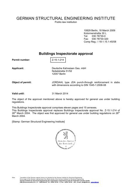
GERMAN STRUCTURAL ENGINEERING INSTITUTE - Jordahl
GERMAN STRUCTURAL ENGINEERING INSTITUTE - Jordahl
GERMAN STRUCTURAL ENGINEERING INSTITUTE - Jordahl

Create successful ePaper yourself
Turn your PDF publications into a flip-book with our unique Google optimized e-Paper software.
<strong>GERMAN</strong> <strong>STRUCTURAL</strong> <strong>ENGINEERING</strong> <strong>INSTITUTE</strong><br />
Public-law institution<br />
10829 Berlin, 18 March 2009<br />
Kolonnenstraße 30 L<br />
Tel: 030 78730-0<br />
Fax: 030 78730-320<br />
Comp Reg.: I 18-1.15.1-45/08<br />
Buildings Inspectorate approval<br />
Permit number:<br />
Z-15.1-214<br />
Applicant:<br />
Deutsche Kahneisen Ges. mbH<br />
Nobelstraße 51/52<br />
12057 Berlin<br />
Object of permit:<br />
JORDAHL type JDA punch-through reinforcement in slabs<br />
with dimensions according to DIN 1045-1:2008-08<br />
Valid until: 31 March 2014<br />
The object of the approval mentioned above is hereby approved for general use under building<br />
regulations.<br />
This Buildings Inspectorate approval comprises eleven pages and 15 annexes.<br />
This Buildings Inspectorate approval replaces Buildings Inspectorate approval No. Z-15.1-214 of<br />
26 th March 2004. The object was first approved for general use under building regulations on 26 th<br />
March 2004.<br />
[Stamp: German Structural Engineering Institute]<br />
Note:<br />
Translation of the German original version not checked by the German Institute for Structural Engineering.<br />
Every page of the German original bears the official stamp of the German Institute for Structural Engineering.<br />
German Institute for Structural Engineering [An organization supported by both the Federation and the Länder.<br />
DIBt [Kolonnenstrße 30 L, D – 10829 Berlin, Tel: +4930 78730 – 0, Fax: +4930 78730 – 320 , E-mail: dibt@dibt.de , www.dibt.de
Page 2 of Buildings Inspectorate approval no. Z-15.1-214 dated 18 March 2009<br />
I. GENERAL PROVISIONS<br />
1 The Buildings Inspectorate approval constitutes confirmation that the object of the permit<br />
may be used or deployed in accordance with Land building regulations.<br />
2 The Buildings Inspectorate approval does not replace the licences, permissions and<br />
certifications prescribed by law in order to carry out a building project.<br />
3 The Buildings Inspectorate approval is granted without prejudice to the rights of third parties,<br />
in particular private intellectual property rights.<br />
4 Those manufacturing and marketing the object of the permit must, without prejudice to more<br />
extensive regulations set out in the "Special Provisions", make copies of the Buildings<br />
Inspectorate approval available to those using or deploying the object of the permit, and<br />
must indicate that the Buildings Inspectorate approval must be present at the site where it is<br />
used. The authorities involved must, on request, be given copies of the Buildings<br />
Inspectorate approval.<br />
5 The Buildings Inspectorate approval may only be duplicated in its entirety. Publication of an<br />
excerpt requires permission from the German Structural Engineering Institute. Texts and<br />
drawings from publicity documents must not contradict the Buildings Inspectorate approval.<br />
Translations of the Buildings Inspectorate approval must contain the words "Translation of<br />
the original German version not checked by the German Structural Engineering Institute".<br />
6 The Buildings Inspectorate approval is granted on a revocable basis. The provisions of the<br />
Buildings Inspectorate approval may be subsequently extended and amended, in particular<br />
if new technical knowledge should necessitate this.<br />
Note:<br />
Translation of the German original version not checked by the German Institute for Structural Engineering.<br />
Every page of the German original bears the official stamp of the German Institute for Structural Engineering.
Page 3 of Buildings Inspectorate approval no. Z-15.1-214 dated 18 March 2009<br />
II. SPECIAL PROVISIONS<br />
1. Object of permit and scope of deployment<br />
The type JDA punch-through reinforcement consists of anchors made from reinforcing steel<br />
bars BSt 500 S, diameter = 10, 12, 14, 16, 20 or 25 mm, with heads apposed on both ends.<br />
The anchors are fixed to assembly bars to support them in position.<br />
The diameter of the apposed anchor heads is three times the diameter of the shaft. The<br />
reinforcement components must correspond to Annex 1.<br />
The type JDA punch-through reinforcement is used as punch-through reinforcement in slabs<br />
produced in accordance with DIN 1045-1 1 , section 10.5. The slabs must be made of normal<br />
concrete, hardness rating C 20/25 to C 50/60. The reinforcement components must be<br />
arranged in such a way that the anchors standing up perpendicularly are arranged in a star<br />
shape for support. The reinforcement components may be used for primarily static and for<br />
primarily non-static loads.<br />
2 Provisions concerning the construction product<br />
2.1 Requirements in relation to properties<br />
The anchors must have the properties of a BSt 500 S in accordance with DIN 488-1 2 . The<br />
breaking load must correspond to the technical terms and conditions of delivery, as filed by<br />
the German Structural Engineering Institute.<br />
If assembly rods connected to the anchors by tack welding are used to secure their position,<br />
these must be made of reinforcing steel BSt 500 S or BSt 500 NR in accordance with DIN<br />
488 2 or BST 500 NR according to Buildings Inspectorate approval or rod or sheet steel<br />
suitable for welding, with increased corrosion resistance, in accordance with Buildings<br />
Inspectorate approval no. Z-30.3-6 3 or from construction steel S 235 JR in accordance with<br />
DIN EN 10025-2 4 .<br />
2.2 Manufacture, packaging, transport, storage and marking<br />
2.2.1 Manufacture<br />
The anchor heads are apposed in the manufacturing plant. At the same time the mark is<br />
indented into both heads. At least two anchors are joined together to form a reinforcement<br />
component, and a reinforcement component may only contain anchors of the same<br />
diameter.<br />
2.2.1.1 Type JDA punch-through reinforcement, normal version<br />
The anchors are welded to reinforcing steel with a diameter of 6 to 10 mm, to reinforcing<br />
steel bars or to sheet steel (tack welding), to secure the position of the double-headed<br />
anchor during concreting (see Annex 2).<br />
2.2.1.2 JDA standard components<br />
Two or three double-headed anchors are welded to reinforcing steel components with a<br />
diameter of 6 to 10 mm, or to sheet steel components (tack welding), to secure the position<br />
of the double-headed anchor during concreting. The length of the assembly frames and<br />
positioning of the anchors are as set out in Annex 3.<br />
Note:<br />
Translation of the German original version not checked by the German Institute for Structural Engineering.<br />
Every page of the German original bears the official stamp of the German Institute for Structural Engineering.
Page 4 of Buildings Inspectorate approval no. Z-15.1-214 dated 18 March 2009<br />
2.2.1.3 Punch-through reinforcement type JDA, MS and GT versions, for use in system floors.<br />
The anchors are welded to BSt 500 S reinforcing steel components (tack welding), to secure<br />
their position during concreting. If the assembly bars are welded to the shaft of the anchors,<br />
then for anchors with a diameter of up to 16 mm, assembly bars with a diameter of 6 mm,<br />
and for larger anchor diameters, assembly bars with a diameter of 8 mm should be used.<br />
The shear resistance of the welding junctions between the anchor shaft and the assembly<br />
bar should not, for anchors with a shaft thickness of ≤ 12 mm, be less than 30% or more<br />
than 60%, and for larger diameters it should be no more than 50% of the fluid force of the<br />
relevant anchor. The distance between the lower side of the anchor heads on the side of the<br />
pressure area and the assembly bar should be a maximum of 80 mm (see Annexes 4 and<br />
5). The same correspondingly also applies to anchors which are welded to the upper flange<br />
of lattice girders (see Annexes 4 to 6).<br />
2.2.1.4 Punch-through reinforcement type JDA, FT version with temporary position securing, for use<br />
in system floors.<br />
Steel bars with a diameter of 4 mm to 6 mm are welded to at least two anchors in a<br />
reinforcement component as spacers, which serve to secure their position during concreting.<br />
For this purpose, for anchors with<br />
Diameter (mm) 10 12 14 16 20 25<br />
Spacer with diameter (mm) ≤ 5 ≤ 5 ≤ 5 ≤ 6 ≤ 6 ≤ 6<br />
The spacers should be applied at a maximum distance of 80 mm from the outer edge of the<br />
anchor head on the pressure area side.<br />
The upper anchor heads are protected in an assembly support until the concrete in the<br />
system slab has set. The temporary positioning support consists of a patented plastic lock<br />
as set out in Annex 7 or Annex 8, the properties of the materials for which are filed with the<br />
German Structural Engineering Institute, and which remains on the anchor heads until the<br />
concrete has set. When the assembly support is removed, section 4 of this Buildings<br />
Inspectorate approval should be complied with.<br />
2.2.2 Packaging, transportation and storage<br />
Packaging, transportation and storage must take place in such a way that the reinforcement<br />
components are not damaged. When the punch-through reinforcement is used in readymade<br />
floor components, Annex 15 should be complied with.<br />
2.2.3 Marking<br />
The delivery note for the reinforcement components must be marked by the manufacturer<br />
using the compliance mark (Ü mark) in accordance with the compliance mark regulations of<br />
the individual Länder and must at least state the anchor diameter and anchor length. Items<br />
may only be labelled if the conditions set out in section 2.3 (proof of compliance) are fulfilled.<br />
A mark in accordance with Annex 1 should be indented into each head of the anchors, and<br />
should indicate the manufacturing plant and the anchor diameter. The key for the<br />
correspondence of the manufacturing plant should be filed with the German Structural<br />
Engineering Institute and the outside supervisory body. On the positioning support<br />
(assembly bars or assembly frames) and in JDA components with a temporary positioning<br />
support, the approval number should be applied in a weatherproof format to the anchor<br />
closest to the supports in each reinforcement component.<br />
Note:<br />
Translation of the German original version not checked by the German Institute for Structural Engineering.<br />
Every page of the German original bears the official stamp of the German Institute for Structural Engineering.
Page 5 of Buildings Inspectorate approval no. Z-15.1-214 dated 18 March 2009<br />
2.3 Proof of compliance<br />
2.3.1 General<br />
Confirmation that the reinforcements are compliant with the stipulations of this Buildings<br />
Inspectorate approval must be provided for every manufacturing plant, by means of a<br />
certificate of compliance based on production control within the plant and regular third-party<br />
surveillance, including an initial test of the reinforcements in accordance with the following<br />
stipulations.<br />
For the purpose of granting the certificate of compliance and the third-party surveillance,<br />
including the product checks that must be carried out as part of this process, the<br />
manufacturer of the reinforcements must commission a certification body recognised for the<br />
purpose and a monitoring body recognised for the purpose.<br />
The German Structural Engineering Institute must be given, for its own information, a copy<br />
of the certificate of compliance issued by the certification body.<br />
The German Structural Engineering Institute must also be given a copy of the report on the<br />
initial check for its own information.<br />
2.3.2 Internal production control within the plant<br />
An internal production control system must be set up and implemented in every<br />
manufacturing plant. An internal production control system means continuous monitoring of<br />
production carried out by the manufacturer, whereby the manufacturer ensures that the<br />
building products manufactured by him are in accordance with the provisions of this<br />
Buildings Inspectorate approval. The internal production control system should at least<br />
include the measures set out in the audit plan. The audit plan is filed with the German<br />
Structural Engineering Institute and the body responsible for monitoring.<br />
The results of the internal production control system must be recorded and evaluated. The<br />
records must, in addition to the details set out in the audit plan, contain at least the following<br />
information:<br />
- Description of the building product<br />
- Type of check or audit<br />
- Date of manufacture and audit of the building product<br />
- Result of the checks and audits and comparison with requirements<br />
- Signature of the person responsible for the internal production control system.<br />
The records must be kept for at least five years and presented to the monitoring body<br />
commissioned to carry out third-party monitoring. They must be submitted to the German<br />
Structural Engineering Institute and to the competent highest building regulations authority<br />
on request. In the event of an unsatisfactory audit result, the manufacturer must take the<br />
required action without delay to remedy the defect. Building products that do not meet<br />
requirements must be handled in such a way that confusion with compliant products is<br />
impossible. After the defect is remedied - insofar as it is technically possible and necessary<br />
in order to prove that the defect has been remedied - the relevant audit must be repeated<br />
without delay.<br />
2.3.3 Third-party monitoring<br />
In every manufacturing plant the internal production control system must be checked by a<br />
third-party monitoring system, on a regular basis but at least twice a year. In the context of<br />
third-party monitoring, an initial check of the reinforcements must be carried out and<br />
samples may also be taken for sample testing. The sampling and testing processes are the<br />
responsibility of the corresponding monitoring body. In relation to the audit of the internal<br />
production control system, at least the audits indicated in the audit plan that has been filed<br />
must be carried out. The results of certification and third-party monitoring must be kept for at<br />
Note:<br />
Translation of the German original version not checked by the German Institute for Structural Engineering.<br />
Every page of the German original bears the official stamp of the German Institute for Structural Engineering.
Page 6 of Buildings Inspectorate approval no. Z-15.1-214 dated 18 March 2009<br />
least five years. They must be presented to the German Structural Engineering Institute by<br />
the certification body or the monitoring body on request.<br />
3 Design and dimensioning provisions<br />
3.1 General<br />
Calculation of the section sizes and dimensions of the slabs and the shear force that acts on<br />
them and proof of their load-bearing capacity across predefined verification sections is<br />
carried out in accordance with DIN 1045-1 1 , unless stipulated to the contrary below.<br />
3.2 Design<br />
Contrary to DIN 1045-1 1 , section 13.3.1, the minimum slab thickness is 18 cm. The<br />
reinforcement required across the bending support must correspond to DIN 1045-1 1 , section<br />
13.3.2. The anchors that are set perpendicularly must always be arranged in the direction of<br />
the shear forces that are applied (component rows) and arranged in a star-shape to provide<br />
support. The lower anchor heads must reach at least to the bottom of the lowest<br />
reinforcement layer, and the upper anchor heads must reach to the top of the top<br />
reinforcement layer.<br />
Only anchors of identical diameter may be used for support in the punch-through area.<br />
The implementation planning must lead to the punch-through reinforcement being installed<br />
correctly into the concrete steel reinforcement network and, where applicable, into available<br />
lattice girders in accordance with the said Buildings Inspectorate approval. As a rule, this<br />
planning includes a suitable scale component drawing of the region with the punch-through<br />
reinforcement showing all reinforcements, steel reinforcing bars and the reinforcing steel mesh<br />
or lattice girders.<br />
Free edges must be enclosed in accordance with DIN 1045-1 1 , figure 71. If reinforcements in<br />
accordance with section 2.2.1.3 are used with assembly bars in reinforcing steel welded to the<br />
anchor shaft (or if the reinforcements are fixed to the upper flange of lattice girders), then the<br />
perpendicular bars (upper flanges of lattice girders) should, if possible, be in the concrete<br />
pressure area and certainly no higher than 8cm above the anchor heads on the pressure area<br />
side.<br />
3.3 Dimensions<br />
3.3.1 General<br />
Proof that the slab is secured against punching through is provided in accordance with DIN<br />
1045-1 1 , section 10.5.3, insofar as no stipulation to the contrary is set out below.<br />
DIN 1045-1 1 , section 10.5.2 (14) is not applicable.<br />
The increase in the resistance to shear force achieved by using angled tension components<br />
may be taken into account in accordance with DIN 1045 1 , section 10.5.3 (5).<br />
In order to determine the maximum load-bearing capacity, the normal tension with a<br />
favourable effect, σ cd , must not be taken into account.<br />
Outside the punch-through reinforcement, the normal tension in the floor should be defined in<br />
the mean of the outer verification section of the slab in accordance with DIN 1045-1 1 , section<br />
10.5.4.<br />
A distinction is made below between areas C and D close to the supports.<br />
Area C is the slab section at a distance of no more than 1 d from the support section. In JDA<br />
standard components in accordance with section 2.2.1.2 this is no more than 1.125 d from the<br />
support section). Area D is the slab section at a distance of no more than 4 d from the support<br />
section but excluding area C.<br />
Note:<br />
Translation of the German original version not checked by the German Institute for Structural Engineering.<br />
Every page of the German original bears the official stamp of the German Institute for Structural Engineering.
Page 7 of Buildings Inspectorate approval no. Z-15.1-214 dated 18 March 2009<br />
Measurement of the entire effective shear force including correction value β is carried out in<br />
the following steps:<br />
(i) Calculating of the load-bearing capacity of the slab without punch-through reinforcements<br />
to check the maximum load-bearing capacity, taking into account the special regulations<br />
for edge and corner supports and supports close to openings in the slab.<br />
(ii) Checking whether the shear force that can be absorbed - including correction value β -<br />
(iii)<br />
does not exceed that maximum load bearing capacity (cf. section 3.3.2.1)<br />
Dimensioning of the punch-through reinforcement in area C for all the shear force to be<br />
absorbed (including correction value β) taking into account<br />
- the special regulations for thick slabs<br />
- the determination of the required component rows and the diameter,<br />
- the spacing rules set out in section 3.3.5.<br />
Shear force components with a favourable effect due to angled tension components may<br />
only be taken into account when dimensioning the anchoring system if the effect exists<br />
both in area C and in area D. Shear force components with an unfavourable effect must<br />
always be taken into account in their entirety.<br />
(iv) Determining the reinforcement in area D by continuation of the component rows from<br />
area C and, where applicable, by arranging additional component rows to fulfil the<br />
spacing rules in accordance with section 3.3.5.<br />
3.3.2 Proof of security against punching through<br />
3.3.2.1 Maximum load-bearing capacity in the punch-through area.<br />
The maximum shear force bearing capacity for slabs with punch-through reinforcements in<br />
the critical circular section is as follows, contrary to equation (107) in DIN 1045-1 1 :<br />
where<br />
deviating from DIN 1045-1 1 in accordance with section 3.3.2.2 must<br />
be calculated for inner, edge and corner supports.<br />
The following must be demonstrated:<br />
u krit the size of the critical circular section in accordance with section<br />
10.5.2 of DIN 1045-1 1 , DIN 1045-1 1 , section 10.5.2 (14) not being<br />
applicable in this case (see also 3.3.1).<br />
β Load enhancement factor for horizontally non-displaceable positioned<br />
floor systems according to Table 1 or<br />
alternatively ß according to DIN 1045-1 1 , fig. 44 or according to<br />
Volume 525 5 of the DAfStb, section 10.5.3<br />
Table 1: Correction values for more precise determination of load enhancing factors β<br />
Correction value Inner supports Corner supports Edge supports<br />
I s<br />
e<br />
1.05<br />
1.05<br />
5<br />
1<br />
⎛ e ⎞<br />
⎜<br />
1.09 · c<br />
⎟<br />
⎝ ⎠<br />
5<br />
⎛<br />
⎜<br />
c<br />
⎝ c<br />
y<br />
⎞<br />
⎟<br />
⎠<br />
e<br />
0.15c<br />
x<br />
+ 5<br />
1.17 · β<br />
1 + 0.2 ·<br />
I s<br />
d<br />
≥ 1<br />
Distance from the outermost anchoring row to the support section<br />
M<br />
Ed,Knoten<br />
resulting mean of the floor support force e =<br />
V<br />
Ed<br />
⎛<br />
1+<br />
⎜<br />
⎝<br />
e<br />
1.25 ·<br />
1.17 · β<br />
1 + 0.15 ·<br />
I s<br />
d<br />
⎞<br />
c<br />
⎟<br />
⎠<br />
≥ 1<br />
5<br />
⎛<br />
⎜<br />
c<br />
⎝ c<br />
x<br />
y<br />
⎞<br />
⎟<br />
⎠<br />
e<br />
0.15c<br />
Note:<br />
Translation of the German original version not checked by the German Institute for Structural Engineering.<br />
Every page of the German original bears the official stamp of the German Institute for Structural Engineering.
Page 8 of Buildings Inspectorate approval no. Z-15.1-214 dated 18 March 2009<br />
on bending in two axes, e is defined as:<br />
e =<br />
2<br />
2<br />
M<br />
Ed,Knoten,x<br />
+ M<br />
Ed,Knoten,y<br />
VEd<br />
M ed,Knoten Resulting support compression moment of the floor-support connection<br />
c x Edge supports: Edge length of the supports perpendicular to the free edge of the floor<br />
Corner supports: Longer edge length of the supports<br />
c y Edge supports: Edge length of the supports parallel to the free floor edge<br />
Corner supports: Shorter edge length of the supports<br />
c Square corner and edge supports: c x<br />
Rectangular corner and edge supports;<br />
2 2<br />
0.5 · ( c<br />
x<br />
+ c y<br />
)<br />
Rounded corner and edge supports: 0.9.I c<br />
I c :<br />
Support diameter<br />
3.3.2.2 Calculated values for shear force capacity<br />
The critical circular section must be placed, in accordance with DIN 1045-1 1 , section 10.5.2,<br />
for inner supports, and supports close to openings in the slab. Supports that are less than<br />
6 d from at least one edge of the slab count as edge or corner supports.<br />
Note:<br />
Translation of the German original version not checked by the German Institute for Structural Engineering.<br />
Every page of the German original bears the official stamp of the German Institute for Structural Engineering.
Page 9 of Buildings Inspectorate approval no. Z-15.1-214 dated 18 March 2009<br />
For this purpose the circular section should be defined on the basis of DIN 1045-1 1 , figure 41,<br />
whereby 6 d should be taken as the distance from the edge (instead of 3 d in accordance with<br />
figure 41).<br />
If the definition of a circular section in accordance with DIN 1045-1 1 , figure 39 gives rise to a smaller<br />
circular section length as a result, then this is definitive (see Annexes 11 to 14).<br />
In the critical circular section, the shear force capacity v Rd.ct of the slab to calculate the maximum<br />
load bearing force is calculated from:<br />
1<br />
⎡<br />
⎤<br />
3<br />
v Rd , ct<br />
= ⎢0.14 · κ (100 · ρl<br />
· f ck<br />
) ⎥ · d[<br />
MN / m]<br />
⎣<br />
⎦<br />
where:<br />
κ the scaling factor according to equation (106) in DIN 1045-1,<br />
ρt =<br />
f yk<br />
f ck<br />
⎪⎧<br />
f ⎪⎫<br />
ck<br />
ρlx · ρlx<br />
≤ min⎨0.306<br />
: 0. 02⎬<br />
and f yk ≤ 500 N/mm 2 ,<br />
⎪⎩ f<br />
yk ⎪⎭<br />
characteristic value for the extension boundary of the reinforcing steel,<br />
characteristic value for the cylindrical pressure resistance of the concrete.<br />
In the outer circular section at a distance of 1.5 d from the outermost anchor, the shear force<br />
capacity v Rd.ct.a is given by:<br />
βred<br />
· VEd<br />
auβen<br />
< vRd<br />
, ct<br />
= vRd<br />
, ct·<br />
κ<br />
a<br />
u<br />
a<br />
Where<br />
1<br />
κ a 0. 714<br />
I<br />
1 0.1· s<br />
≥ and I s is the distance from the outermost anchor of a component<br />
+<br />
d<br />
row in the support section<br />
β red<br />
According to Table 1 or alternatively β in accordance with DIN 1045-1 1 , figure 44 or<br />
according to Volume 525 of the DAfStb, section 10.5.3.<br />
v Rd.ct in accordance with DIN 1045-1:2001-07, equation (105)<br />
3.3.3 Proof against fatigue<br />
The proof against fatigue should be calculated on the basis of DIN 1045-1:2001-07, section<br />
10.8.3, but for load fluctuation figures of N ≤ 2*10 6 . The corresponding tension value is then<br />
Δσ Rsk (2*10 6 ) = 70 N/mm 2.<br />
For higher load fluctuation figures the proof has not been evaluated in the context of this<br />
Buildings Inspectorate approval.<br />
Taking into account this steel tension verification limit, proof against fatigue for concrete,<br />
under pressure challenges in accordance with DIN 1045-1 1 , section 10.8.4(4) does not need<br />
to be carried out in normal multi-storey buildings.<br />
3.3.4 Dimensioning of the punch-through reinforcement<br />
In area C in accordance with section 3.3.1 the number of anchors should be defined in such<br />
a way that the inequality set out below is satisfied for the measurement value including<br />
factor β:<br />
β ·V Ed ≤V Rd,sy where<br />
β<br />
Factor to take into account the non-rotational symmetrical distribution of shear force<br />
within the circular section close to edge and corner supports and for inner supports<br />
in irregular systems in accordance with Table 1 or, alternatively, in accordance with<br />
DIN 1045-1, fig. 44, or according to Volume 525 of the DAfStb, section 10.5.3.<br />
Note:<br />
Translation of the German original version not checked by the German Institute for Structural Engineering.<br />
Every page of the German original bears the official stamp of the German Institute for Structural Engineering.
Page 10 of Buildings Inspectorate approval no. Z-15.1-214 dated 18 March 2009<br />
mc<br />
· nc<br />
V<br />
Rd , sy<br />
= · As<br />
_ i<br />
· f<br />
yd<br />
η<br />
Where A s_i the area of the verification section of one double-headed anchor<br />
n c The number of anchors on a component row in area C (cf. Annex 9)<br />
m c The number of component rows in area C (cf. Annex 9)<br />
f yd<br />
η<br />
Calculated value for the limit of the extent of the reinforcing steel (≤ 435 MPa)<br />
Factor to take into account the thickness of the slab depending on the static height:<br />
η =<br />
= 1.0 where d ≤ 200 mm<br />
= 1.6 where d ≥ 800 mm<br />
Intermediate values should be interpolated linearly.<br />
The anchors in area D are the anchors that must be arranged in sufficient numbers to satisfy<br />
the distance rules set out in Section 3.3.5:<br />
3.3.5 Arrangement of anchors and distances between them.<br />
For every component row situated on a radius extending from the support, at least two<br />
anchors must be placed in area C.<br />
For thick slabs (d>50 cm) and simultaneous support diameters Ic < 50 cm, for increased<br />
loads (V Ed > 0.85 V Rd . max ) at least three anchors must be put in place.<br />
The component rows required in area C must be continued, taking into account the spacing<br />
rules for this section, up to the edge of the area with punch-through reinforcements. If<br />
applicable, additional component rows that are needed in area D to comply with the spacing<br />
rules for this area should be distributed equally between the rows calculated from area C.<br />
If, within a single slab, shear force reinforcements are required outside area D, then, for<br />
horizontally non-displaceable flat floors with identical loads and approximately identical<br />
support distances, the anchors should be arranged as shear force protection at a distance of<br />
up to 1.5 d from the outer edge of area D, if the permissible anchor distances in this section<br />
are complied with and the component rows from area D are continued.<br />
The anchor closest to the loaded area (support) must, for this purpose, have a distance of<br />
between 0.35 d and 0.5 d.<br />
If JDA standard components are used as set out in Annex 10, area C may be extended to a<br />
distance of 1.125 d from the support section.<br />
The distances between the anchors must not exceed the following values:<br />
- In the direction of the radii extending from the loaded area (support),<br />
in areas C and D: 0.75 d.<br />
Additionally, for distances s D , the following applies in the radial direction in area D:<br />
s<br />
D<br />
=<br />
3 · d<br />
2 n<br />
c<br />
m<br />
m<br />
D<br />
C<br />
≤ 0.75 d<br />
where<br />
m c is the number of component rows in area C<br />
m D is the number of component rows in area D,<br />
n c is the number of anchors in a component row in area C (see Annex 9)<br />
Note:<br />
Translation of the German original version not checked by the German Institute for Structural Engineering.<br />
Every page of the German original bears the official stamp of the German Institute for Structural Engineering.
Page 11 of Buildings Inspectorate approval no. Z-15.1-214 dated 18 March 2009<br />
- In a tangential direction in area C: 1.7 d<br />
- In a tangential direction in area D: 3.5 d<br />
3.3.6 Verification of fire resistance class<br />
For verification of fire resistance class, DIN 4102-4 6 is applicable, in conjunction with DIN<br />
4102-22 7 or DIN V ENV 1992-1-2 8 in conjunction with DIN Technical Report 92 9 .<br />
The necessary concrete covering for the anchor heads and assembly frames must be<br />
maintained in the region of the reinforcements.<br />
4 Implementation provisions<br />
Deviations of more than one tenth of the slab thickness, compared to the planning<br />
documents, in the position of and the distances between the anchors installed one relative<br />
to another in the punch-through reinforcement in the layout of the slab are inadmissible.<br />
The lower anchor heads of the double-headed bolts must extend at least as far as the lower<br />
edge of the lowermost reinforcement position and the upper anchor heads must extend at<br />
least as far as the upper edge of the uppermost reinforcement position. However, the<br />
minimum and maximum values specified in the corresponding documents apply<br />
unreservedly to the dimensions of and distances between the individual anchor bolts of the<br />
punch-through reinforcement components<br />
When using FT version Type JDA components with temporary position supports for system<br />
floors, in accordance with Annexes 7 or 8 (cf. section 2.2.1.4), the assembly support for the<br />
upper anchor head must be removed at the earliest when the concrete of the finished slab<br />
has a characteristic hardness of f c,cyl = 12 N/mm 2 .<br />
When using JDA reinforcements in system floors, in the punch-through area - if component<br />
impacts cannot be avoided - to ensure safe transfer of pressure forces, the impact joints<br />
should be made at least 4 cm wide and filled with concrete locally.<br />
Häusler<br />
Note:<br />
Translation of the German original version not checked by the German Institute for Structural Engineering.<br />
Every page of the German original bears the official stamp of the German Institute for Structural Engineering.
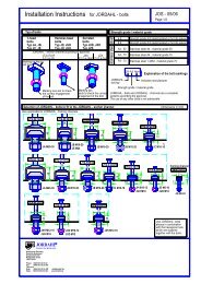
Anchor shape<br />
On both sides<br />
Marking<br />
e.g. <strong>Jordahl</strong><br />
Double-headed anchor<br />
M 12<br />
Anchor height<br />
Alternative marking<br />
On both sides<br />
e.g. <strong>Jordahl</strong><br />
Double-headed anchor<br />
M 12<br />
Marking<br />
Anchor<br />
Diameter<br />
Head diameter<br />
Head<br />
height<br />
Anchor crosssection<br />
Load bearing<br />
capacity<br />
JORDAHL®<br />
REINFORCEMENT<br />
JORDAHL<br />
TECHNOLOGY<br />
punch-through reinforcement<br />
Type JDA<br />
Deutsche Kahneisen Annex 1<br />
Gesellschaft mbH<br />
Double-headed anchor<br />
Nobelstraße 51-55<br />
Dimensions<br />
D-12057 Berlin Load bearing capacities to Buildings<br />
Tel. 030/6 82 83-02<br />
Inspectorate Approval<br />
Fax 030/6 82 83-498 No. Z-15. 1-214<br />
Dated 18 March 2009<br />
Note:<br />
Translation of the German original version not checked by the German Institute for Structural Engineering.<br />
Every page of the German original bears the official stamp of the German Institute for Structural Engineering.
Punch-through reinforcement with double-headed anchors<br />
Material, fixing frame<br />
Frame<br />
Marking on<br />
both sides<br />
Frame reinforcement<br />
Detail "Y"<br />
Materials:<br />
Anchor:<br />
Frames:<br />
BSt 500S<br />
S 235 JR<br />
(1.0037 or ST 37-2)<br />
1.4571/1.4401 (A4)<br />
DIBt Approval No. Z-30.3-6<br />
Frame in<br />
Perforated strip<br />
w/d = 30/4<br />
Welded from the side Welded from the side Welded in the<br />
Below the frame above the head middle in the<br />
hole in the frame<br />
JORDAHL®<br />
REINFORCEMENT<br />
JORDAHL<br />
TECHNOLOGY<br />
punch-through reinforcement<br />
Type JDA<br />
Deutsche Kahneisen Annex 2<br />
Gesellschaft mbH JDA punch-through reinforcement<br />
Nobelstraße 51-55<br />
Materials<br />
D-12057 Berlin Fixing frame to Buildings<br />
Tel. 030/6 82 83-02<br />
Inspectorate Approval<br />
Fax 030/6 82 83-498 No. Z-15. 1-214<br />
Dated 18 March 2009<br />
Note:<br />
Translation of the German original version not checked by the German Institute for Structural Engineering.<br />
Every page of the German original bears the official stamp of the German Institute for Structural Engineering.
JDA standard components<br />
Support<br />
Description: 2-part component<br />
[bis = to]<br />
Support<br />
Description: 3-part component<br />
JDA standard components are manufactured with a symmetrical overlap so that<br />
components can be correctly matched to each other. If multiple components are used they<br />
must be pushed up against each other.<br />
JORDAHL®<br />
REINFORCEMENT<br />
JORDAHL<br />
TECHNOLOGY<br />
punch-through reinforcement<br />
Type JDA<br />
Deutsche Kahneisen Annex 3<br />
Gesellschaft mbH JDA punch-through reinforcement<br />
Nobelstraße 51-55 Representation of JDA to Buildings<br />
D-12057 Berlin standard components Inspectorate Approval<br />
Tel. 030/6 82 83-02<br />
Fax 030/6 82 83-498 No. Z-15. 1-214<br />
Dated 18 March 2009<br />
Note:<br />
Translation of the German original version not checked by the German Institute for Structural Engineering.<br />
Every page of the German original bears the official stamp of the German Institute for Structural Engineering.
Assembly of JDA reinforcements in prefabricated floor units<br />
Positioning of JDA reinforcements. MS version on the lattice girder of a prefabricated floor unit with supporting<br />
layer of local concrete<br />
Assembly bars diameter = 5-8 mm<br />
Depending on shaft diameter<br />
Marking<br />
On both sides<br />
Linked by tack/spot<br />
welds<br />
Anchor height hA<br />
Attached to lattice<br />
girders as per instructions<br />
Section A-A<br />
Material<br />
Anchor: BSt 500S<br />
Assembly bars: BSt 500S<br />
JORDAHL ®<br />
JORDAHL<br />
REINFORCEMENT<br />
punch-through reinforcement<br />
TECHNOLOGY Type JDA Annex 4<br />
Deutsche Kahneisen Anchor securing system to Buildings<br />
Gesellschaft mbH MS version Inspectorate Approval<br />
Nobelstraße 51-55 for use in prefabricated No. Z-15. 1-214<br />
D-12057 Berlin floor units<br />
Tel. 030/6 82 83-02 Dated 18 March 2009<br />
Fax 030/6 82 83-498<br />
Note:<br />
Translation of the German original version not checked by the German Institute for Structural Engineering.<br />
Every page of the German original bears the official stamp of the German Institute for Structural Engineering.
Assembly of JDA reinforcements<br />
MS version in prefabricated floor units<br />
Positioning of JDA reinforcements, MS version on the lattice girders of a prefabricated floor<br />
unit with supporting local concrete layer.<br />
JORDAHL®<br />
REINFORCEMENT<br />
JORDAHL<br />
TECHNOLOGY<br />
punch-through reinforcement<br />
Type JDA<br />
Deutsche Kahneisen Annex 5<br />
Gesellschaft mbH Assembly of reinforcements<br />
Nobelstraße 51-55<br />
MS version<br />
D-12057 Berlin for use in system to Buildings<br />
Tel. 030/6 82 83-02 floor units Inspectorate Approval<br />
Fax 030/6 82 83-498 No. Z-15. 1-214<br />
Dated 18 March 2009<br />
Note:<br />
Translation of the German original version not checked by the German Institute for Structural Engineering.<br />
Every page of the German original bears the official stamp of the German Institute for Structural Engineering.
Reinforcements with double-headed anchors<br />
GT version<br />
Secured in position by fixing to lattice girders<br />
Lattice girders in accordance with<br />
Buildings Inspectorate approval<br />
Fixed by<br />
Tack/spot welding<br />
Marking on both sides<br />
Anchor height hA<br />
Materials<br />
Anchor: BSt 500S<br />
Lattice girders: BSt according to current Buildings Inspectorate approval for lattice girders<br />
Section:<br />
JORDAHL®<br />
REINFORCEMENT<br />
JORDAHL<br />
TECHNOLOGY<br />
punch-through reinforcement<br />
Type JDA<br />
Deutsche Kahneisen Annex 6<br />
Gesellschaft mbH<br />
JDA punch-through reinforcement<br />
Nobelstraße 51-55<br />
GT version<br />
D-12057 Berlin Materials and deployment to Buildings<br />
Tel. 030/6 82 83-02 for use in system Inspectorate Approval<br />
Fax 030/6 82 83-498 floor units No. Z-15. 1-214<br />
Dated 18 March 2009<br />
Note:<br />
Translation of the German original version not checked by the German Institute for Structural Engineering.<br />
Every page of the German original bears the official stamp of the German Institute for Structural Engineering.
Punch-through reinforcement with double-headed anchors<br />
FT version with plastic patented lock<br />
For use in system floor units<br />
Anchor height hA<br />
Spacer<br />
D = 6 mm<br />
Anchor - frame connected<br />
by plastic patented lock<br />
JORDAHL®<br />
REINFORCEMENT<br />
JORDAHL<br />
TECHNOLOGY<br />
punch-through reinforcement<br />
Type JDA<br />
Deutsche Kahneisen Annex 7<br />
Gesellschaft mbH<br />
Punch-through reinforcement<br />
Nobelstraße 51-55<br />
FT version<br />
D-12057 Berlin Materials/connections to Buildings<br />
Tel. 030/6 82 83-02<br />
Inspectorate Approval<br />
Fax 030/6 82 83-498 No. Z-15. 1-214<br />
Dated 18 March 2009<br />
Note:<br />
Translation of the German original version not checked by the German Institute for Structural Engineering.<br />
Every page of the German original bears the official stamp of the German Institute for Structural Engineering.
Punch-through reinforcement with double-headed anchors<br />
FT version with patented plastic lock<br />
For use in system floor units<br />
Anchor - frame connected<br />
by patented plastic cap<br />
Spacer<br />
D = 6 mm<br />
Anchor height hA<br />
Connected by patented plastic<br />
lock<br />
JORDAHL®<br />
REINFORCEMENT<br />
JORDAHL<br />
TECHNOLOGY<br />
punch-through reinforcement<br />
Type JDA<br />
Deutsche Kahneisen Annex 8<br />
Gesellschaft mbH<br />
JDA punch-through reinforcement<br />
Nobelstraße 51-55<br />
FT version<br />
D-12057 Berlin Materials/connections to Buildings<br />
Tel. 030/6 82 83-02<br />
Inspectorate Approval<br />
Fax 030/6 82 83-498 No. Z-15. 1-214<br />
Dated 18 March 2009<br />
Note:<br />
Translation of the German original version not checked by the German Institute for Structural Engineering.<br />
Every page of the German original bears the official stamp of the German Institute for Structural Engineering.
Arrangement in principle of punch-through reinforcement<br />
with continuous components<br />
Edge of the area of slab<br />
reinforced with anchors<br />
n c<br />
Anchors per<br />
component row<br />
in area C<br />
m C or m D<br />
Number of component rows<br />
in areas C and D<br />
Additional component<br />
to fulfil distance rules in<br />
Area D<br />
Outer<br />
Verification<br />
section<br />
Area D Area C Support Area C Area D<br />
Section A-A<br />
"Built from above"<br />
Frame above the top reinforcement<br />
"Built from below"<br />
Frame below the lower reinforcement<br />
JORDAHL®<br />
REINFORCEMENT<br />
JORDAHL<br />
TECHNOLOGY<br />
punch-through reinforcement<br />
Type JDA<br />
Deutsche Kahneisen Annex 9<br />
Gesellschaft mbH<br />
JDA punch-through reinforcement<br />
Nobelstraße 51-55<br />
Component arrangement with<br />
D-12057 Berlin continuous components to Buildings<br />
Tel. 030/6 82 83-02<br />
Inspectorate Approval<br />
Fax 030/6 82 83-498 No. Z-15. 1-214<br />
Dated 18 March 2009<br />
Note:<br />
Translation of the German original version not checked by the German Institute for Structural Engineering.<br />
Every page of the German original bears the official stamp of the German Institute for Structural Engineering.
Principles for structuring punch-through reinforcement<br />
with shared standard components<br />
Edge of the area of slab<br />
reinforced with anchors<br />
n c<br />
Anchors per<br />
component row<br />
in area C<br />
m C or m D<br />
Number of component rows<br />
in areas C and D<br />
Additional component<br />
to fulfil distance rules in<br />
Area D<br />
Outer<br />
Key section<br />
Area D Area C Support Area C Area D<br />
Section A-A<br />
"Built from above"<br />
Frame above the top reinforcement<br />
"Built from below"<br />
Frame below the lower reinforcement<br />
JORDAHL®<br />
REINFORCEMENT<br />
JORDAHL<br />
TECHNOLOGY<br />
punch-through reinforcement<br />
Type JDA<br />
Deutsche Kahneisen Annex 10<br />
Gesellschaft mbH<br />
JDA punch-through reinforcement<br />
Nobelstraße 51-55 Component arrangement with to Buildings<br />
D-12057 Berlin standard components Inspectorate Approval<br />
Tel. 030/6 82 83-02 No. Z-15. 1-214<br />
Fax 030/6 82 83-498 Dated 18 March 2009<br />
Note:<br />
Translation of the German original version not checked by the German Institute for Structural Engineering.<br />
Every page of the German original bears the official stamp of the German Institute for Structural Engineering.
Diagram of critical circular sections u krit<br />
a) Load-bearing area (support) is further than 6 d from openings or free edges.<br />
b) Load-bearing area (support) is less than 6 d from openings in the slab.<br />
JORDAHL®<br />
REINFORCEMENT<br />
JORDAHL<br />
TECHNOLOGY<br />
punch-through reinforcement<br />
Type JDA<br />
Deutsche Kahneisen Annex 11<br />
Gesellschaft mbH Punch-through reinforcement<br />
Nobelstraße 51-55 Circular section plan u krit<br />
D-12057 Berlin to Buildings<br />
Tel. 030/6 82 83-02<br />
Inspectorate Approval<br />
Fax 030/6 82 83-498 No. Z-15. 1-214<br />
Dated 18 March 2009<br />
Note:<br />
Translation of the German original version not checked by the German Institute for Structural Engineering.<br />
Every page of the German original bears the official stamp of the German Institute for Structural Engineering.
c) Load-bearing area (support) is less than 3 d from free edges.<br />
free edge<br />
d) Load-bearing area (support) is more than 3 d and less than 6 d from free edges.<br />
The circular section plan with smaller circular section length (u krit 1 or u krit 2) is used to<br />
calculate u krit .<br />
JORDAHL®<br />
REINFORCEMENT<br />
JORDAHL<br />
TECHNOLOGY<br />
punch-through reinforcement<br />
Type JDA<br />
Deutsche Kahneisen Annex 12<br />
Gesellschaft mbH Punch-through reinforcement<br />
Nobelstraße 51-55 Circular section plan u krit<br />
D-12057 Berlin to Buildings<br />
Tel. 030/6 82 83-02<br />
Inspectorate Approval<br />
Fax 030/6 82 83-498 No. Z-15. 1-214<br />
Dated 18 March 2009<br />
Note:<br />
Translation of the German original version not checked by the German Institute for Structural Engineering.<br />
Every page of the German original bears the official stamp of the German Institute for Structural Engineering.
Diagram of circular sections u a<br />
a) Load-bearing area (support) is further than 6 d from openings or free edges.<br />
Support<br />
Support<br />
Area of slab<br />
reinforced with<br />
anchors<br />
Area of slab<br />
reinforced with<br />
anchors<br />
b) Load-bearing area (support) is less than 6 d from openings in the slab.<br />
Area of slab<br />
reinforced with<br />
anchors<br />
JORDAHL®<br />
REINFORCEMENT<br />
JORDAHL<br />
TECHNOLOGY<br />
punch-through reinforcement<br />
Type JDA<br />
Deutsche Kahneisen Annex 13<br />
Gesellschaft mbH<br />
Punch-through reinforcement<br />
Nobelstraße 51-55<br />
Circular section plan u a<br />
D-12057 Berlin to Buildings<br />
Tel. 030/6 82 83-02<br />
Inspectorate Approval<br />
Fax 030/6 82 83-498 No. Z-15. 1-214<br />
Note:<br />
Translation of the German original version not checked by the German Institute for Structural Engineering.<br />
Every page of the German original bears the official stamp of the German Institute for Structural Engineering.
c) Load-bearing area (support) is less than 6 d from free edges.<br />
Dated 18 March 2009<br />
Area of slab<br />
reinforced with<br />
anchors<br />
JORDAHL®<br />
REINFORCEMENT<br />
JORDAHL<br />
TECHNOLOGY<br />
punch-through reinforcement<br />
Type JDA<br />
Deutsche Kahneisen Annex 14<br />
Gesellschaft mbH Punch-through reinforcement<br />
Nobelstraße 51-55<br />
Circular section plan u a<br />
D-12057 Berlin to Buildings<br />
Tel. 030/6 82 83-02<br />
Inspectorate Approval<br />
Fax 030/6 82 83-498 No. Z-15. 1-214<br />
Dated 18 March 2009<br />
Note:<br />
Translation of the German original version not checked by the German Institute for Structural Engineering.<br />
Every page of the German original bears the official stamp of the German Institute for Structural Engineering.
Positioning and transportation when used in system floors<br />
Taller spacers required<br />
When storing and transporting system<br />
floors the JDA reinforcements must be<br />
taken into account, which protrude beyond<br />
the lattice girders because of their height.<br />
The spacers required for storage of system floors<br />
must be correspondingly increased.<br />
JORDAHL®<br />
REINFORCEMENT<br />
JORDAHL<br />
TECHNOLOGY<br />
punch-through reinforcement<br />
Type JDA<br />
Deutsche Kahneisen Annex 15<br />
Gesellschaft mbH Storage and transportation<br />
Nobelstraße 51-55 when used in system floors<br />
D-12057 Berlin to Buildings<br />
Tel. 030/6 82 83-02<br />
Inspectorate Approval<br />
Fax 030/6 82 83-498 No. Z-15. 1-214<br />
Dated 18 March 2009.<br />
Note:<br />
Translation of the German original version not checked by the German Institute for Structural Engineering.<br />
Every page of the German original bears the official stamp of the German Institute for Structural Engineering.