amphenol_MIL-C-38999series3... - Challenger Components Ltd
amphenol_MIL-C-38999series3... - Challenger Components Ltd
amphenol_MIL-C-38999series3... - Challenger Components Ltd

You also want an ePaper? Increase the reach of your titles
YUMPU automatically turns print PDFs into web optimized ePapers that Google loves.
® TM<br />
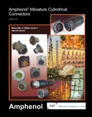
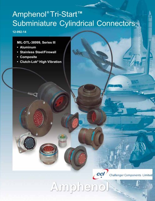
Amphenol Tri-Start<br />
Subminiature Cylindrical Connectors<br />
12-092-14<br />
<strong>MIL</strong>-DTL-38999, Series III<br />
• Aluminum<br />
• Stainless Steel/Firewall<br />
• Composite<br />
• Clutch-Lok ® High Vibration
Table of Contents<br />
Page No.<br />
Series III - The Highest Performance <strong>MIL</strong>-DTL-38999 Connector ...................... 1<br />
Tri-Start Series III Versatility and Options ........................................................... 2<br />
Shell Styles and Key Design Features ............................................................... 3<br />
Test Data .......................................................................................................... 4<br />
Specifications .................................................................................................... 5<br />
Insert Availability and Identification ................................................................ 6, 7<br />
Alternate Positioning .......................................................................................... 8<br />
Insert Arrangements ................................................................................... 9-15<br />
Crimp<br />
TVP00R/CTVP00R Wall Mounting Receptacle .......................................... 16<br />
TVP02R/CTVP02R Box Mounting Receptacle .......................................... 17<br />
TV06R/CTV06R Straight Plug ................................................................... 18<br />
TV26/MTV26 CLUTCH-LOK® Straight Plug .............................................. 19<br />
TV07R/CTV07R Jam Nut Receptacle ....................................................... 20<br />
TV01R/CTV01R Line Receptacle .............................................................. 21<br />
TV09R Flange Mounting Plug .................................................................... 22<br />
Hermetic<br />
TVPS02Y Box Mounting Receptacle ......................................................... 23<br />
TVS07Y Jam Nut Receptacle ................................................................... 24<br />
TVSIY Solder Mounting Receptacle .......................................................... 25<br />
TVSHIY Weld Mounting Recepacle ........................................................... 26<br />
Fail Safe, Lanyard Release<br />
Design Features, Types ............................................................................ 27<br />
D38999/29, D38999/30 Lanyard Release Plug ..................................... 28-30<br />
D38999/31 TV Fail Safe Lanyard Release Plug for <strong>MIL</strong>-STD-1760 ....... 31, 32<br />
Accessories for Lanyard Release Connectors .......................................... 33<br />
Accessories<br />
Receptacle Protection Caps ..................................................................... 34<br />
Plug Protection Caps ................................................................................ 35<br />
Dummy Receptacles ................................................................................ 36<br />
Cable Clamps ........................................................................................... 37<br />
Universal Header Assembly for Flex Print or PC Board Connectors .... 38, 39<br />
Contacts, Sealing Plugs, Plastic/Metal Protection Caps ................................... 40<br />
Contacts (Printed Circuit Board, Wire wrap) .................................................... 41<br />
Application Tools .............................................................................................. 42<br />
How to Order<br />
Amphenol® TV, Metal and Amphenol® TV26 CLUTCH-LOK® ................... 43<br />
D38999, TV Military, Metal and MTV26 CLUTCH-LOK® ............................ 44<br />
Amphenol® CTV, Composite ..................................................................... 45<br />
D38999, CTV Military, Composite .............................................................. 46<br />
Composite Weight Comparisons ..................................................................... 47<br />
Specials (Fiber Optics, Filter Protection, Flex Assemblies,<br />
PCB Applications) ..................................................................................... 48<br />
Specials (Coax, Twinax, Triax Contacts, Ground Plane Connectors,<br />
Press Fit Connectors) ............................................................................. 49<br />
Specials (Quadrax Contacts) ......................................................................... 50<br />
Specials (Deep Reach Shells, Stand-off Flange Shells, Connectors with<br />
Integral Strain Reliefs, ESD Protection, RJ Field Connectors .................. 51<br />
Sales Office and Distributor Listing ................................................................ 52<br />
For additional information concerning Amphenol Tri-Start Connectors, or if there<br />
are special application requirements, contact your local sales office:<br />
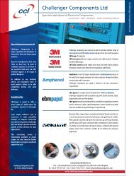
<strong>Challenger</strong> <strong>Components</strong> <strong>Ltd</strong> on +44 (0) 1795 477 255<br />
or Email: office@challengercomponents.com<br />
Web: www.challengercomponents.com<br />
Amphenol Aerospace is a Certified ISO9001 Manufacturer.<br />
Full product range available from: <strong>Challenger</strong> <strong>Components</strong> <strong>Ltd</strong>, Unit 1, Church Road Business Centre, Sittingbourne, Kent ME10 3RS<br />
Tel: +44 (0) 1795 477 255 • Email: office@challengercomponents.com • Web: www.challengercomponents.com
Amphenol ® Tri-Start<br />
Series III - the highest performance<br />
<strong>MIL</strong>-DTL-38999 connector<br />
Composite Tri-Start,<br />
Qualified to <strong>MIL</strong>-DTL-38999, Rev. J<br />
Tri-Start TM <strong>MIL</strong>-DTL-38999 Series III<br />
with Metal Shells - Aluminum, Stainless Steel, Class K Firewall<br />
Amphenol ® Tri-Start <strong>MIL</strong>-DTL-38999* Series III Connectors<br />
offer the highest performance capabilities for both general<br />
duty and severe environment applications. Meeting or exceeding<br />
<strong>MIL</strong>-DTL-38999 Series III requirements, the Tri-Start<br />
connector with standard metal shells (aluminum or stainless<br />
steel with several finish options) offers these features:<br />
• EMI Shielding - solid metal to metal coupling, grounding<br />
fingers, electroless nickel plating, and thicker wall sections<br />
provide superior EMI shielding capability of 65dB minimum<br />
at 10 GHz<br />
• Contact Protection - recessed pins in this 100% scoopproof<br />
connector minimize potential contact damage<br />
• Moisture Resistance - improved interfacial seal design<br />
helps prevent electrolytic erosion of contacts<br />
• Corrosion Resistance - shells of stainless steel or<br />
cadmium over nickel plating withstand a 500 hour salt spray<br />
exposure<br />
• Vibration/Shock - operates under severe high temperature<br />
vibration, through 200°C<br />
• Firewall Capability - available in a stainless steel shell,<br />
class RK, RS<br />
• Lockwiring Eliminated - unique, self-locking, quick<br />
coupling connector eliminates lockwiring<br />
• Quick Coupling - completely mates and self-locks in a<br />
360° turn of the coupling nut<br />
• Inventory Support Commonality - uses standard <strong>MIL</strong>-<br />
DTL-38999 contacts, application tools, insert arrangements<br />
• Electrostatic Discharge Protection (ESD) - protection for<br />
sensitive circuitry without diodes, varistors, etc., with the<br />
use of the Faraday Cage principal which shunts high<br />
voltage, high current discharge events (see page 51)<br />
• Ground Plane Connectors - with metallic insert for<br />
common grounding of coax, triax or twinax contact outer<br />
shield (see page 49)<br />
• Hermetic- air leakage limited to 1 X 10 -7 cm 3 per second<br />
optional<br />
* <strong>MIL</strong>-DTL-38999 Series III supersedes <strong>MIL</strong>-C-38999 Series III.<br />
1<br />
<strong>MIL</strong>-Qualified to <strong>MIL</strong>-DTL-38999, Rev. K, the Amphenol<br />
® Composite Tri-Start Connector offers a lightweight,<br />
corrosion resistant connector with the same high<br />
performance features as its metal counterpart. The<br />
Composite Tri-Start Connector also includes the following<br />
features:<br />
• Lightweight - 17% – 70% weight savings<br />
(17–40% weight savings vs. aluminum)<br />
(60–70% weight savings vs. stainless steel)<br />
See Composite weight comparison chart, pg. 47.<br />
• Corrosion Resistance - available in standard <strong>MIL</strong>-<br />
DTL-38999 olive drab cadmium (175°C) and electroless<br />
nickel plating (200°C), both withstanding 2000<br />
hours of salt spray exposure. The base material is<br />
able to withstand an indefinite exposure to salt spray.<br />
• Durability - 1500 couplings minimum (in reference to<br />
connector couplings, not contacts)<br />
• Extended Life Contact - Mil-approved plating<br />
process which provides 1500 couplings minimum<br />
CLUTCH-LOK TM <strong>MIL</strong>-DTL-38999 Series III<br />
High Vibration Connector<br />
The latest offering from Amphenol in <strong>MIL</strong>-DTL-38999,<br />
the CLUTCH-LOK connector offers:<br />
All advantages of stainless steel/Class K firewall Tri-<br />
Start connectors plus a unique clutch design that<br />
actually tightens itself under vibration.<br />
Features include:<br />
• High degree of differential torque<br />
• No settling back to the next ratchet tooth<br />
• Completely intermateable with all existing<br />
<strong>MIL</strong>-DTL-38999 Series III connectors<br />
• Offers advantage in inaccessible, hard to reach<br />
areas where mating torque is difficult to apply and<br />
complete coupling is not verifiable by inspection<br />
See page 19 for description, 43 and 44 for ordering.<br />
Full product range available from: <strong>Challenger</strong> <strong>Components</strong> <strong>Ltd</strong>, Unit 1, Church Road Business Centre, Sittingbourne, Kent ME10 3RS<br />
Tel: +44 (0) 1795 477 255 • Email: office@challengercomponents.com • Web: www.challengercomponents.com
Amphenol ® Tri-Start<br />
offers more versatility & options<br />
than any other interconnection family<br />
The Tri-Start Connector is the high performance choice<br />
in the D38999 Family.<br />
Originally designed in order to increase the performance levels<br />
of <strong>MIL</strong>-DTL-38999 Series I and II, the Series III was created<br />
to meet high performance connector criteria.<br />
Dynamic features for performance and reliability that were<br />
needed for military, aerospace and ground vehicle applications<br />
were designed into the Series III that include:<br />
• Rapid coupling via a triple-start thread<br />
• Shell-to-shell or metal-to-metal bottoming<br />
• Improved EMI shielding<br />
The Tri-Start Family of connectors has grown and expanded<br />
since its original addition to the 38999 series in order to meet<br />
ever-evolving interconnection product needs. Today, the Tri-<br />
Start family has styles and options that cover a very wide<br />
range to meet not only the highest performance needs of<br />
space applications, but also general duty connector needs.<br />
The Tri-Start Connector Series is second to none in<br />
terms of versatility and customer options.<br />
The broad porfolio includes Tri-Starts with:<br />
• Aluminum and nickel plated stainless steel shells<br />
• Class K Firewalls<br />
• Composite shells<br />
• Clutch-Lok® high vibration design<br />
• Fiber Optics<br />
• Fail-Safe Lanyard Release connectors<br />
• Variety of contact options: shielded, coax, matched impedance<br />
coax, triax, twinax, quadrax, thermocouple, PCB tail and<br />
wire wrap<br />
• Ground plane versions and Press-fit® with compliant pins<br />
• ESD (Electrostatic Discharge) protection<br />
• Filter/Transient protection<br />
• Hermetic versions<br />
• Long reach receptacle styles<br />
• Numerous shell geometries,<br />
finishes and accessories<br />
See more on Tri-Start specials<br />
on pages 48-51.<br />
Fiber Optic Multi-Channel D38999<br />
<strong>MIL</strong>-DTL-38999 with<br />
Shielded Coax Contacts<br />
Filter/Transient<br />
Protection<br />
<strong>MIL</strong>-DTL-38999 Series III<br />
D38999 Ground Plane with<br />
Metallic Insert, Power<br />
Contacts and<br />
Shielded Twinax<br />
Contacts<br />
D38999 with Flex<br />
Termination for<br />
Attachment to PCB<br />
Boards<br />
Hermetic Tri-Start<br />
<strong>MIL</strong>-DTL-38999 Series III<br />
<strong>MIL</strong>-DTL-38999 Lanyard<br />
“Breakaway” Connector<br />
Qualified for <strong>MIL</strong>-STD-1760<br />
D38999 with PC Tail<br />
Coax Contacts and<br />
Alignment Disc<br />
2<br />
Full product range available from: <strong>Challenger</strong> <strong>Components</strong> <strong>Ltd</strong>, Unit 1, Church Road Business Centre, Sittingbourne, Kent ME10 3RS<br />
Tel: +44 (0) 1795 477 255 • Email: office@challengercomponents.com • Web: www.challengercomponents.com
Amphenol ® Tri-Start<br />
shell styles and key<br />
design features<br />
Coupling Nut<br />
Quick Coupling<br />
Thread<br />
Ratchet<br />
Wall Mount Receptacle<br />
Straight Plug<br />
Plug<br />
Shell<br />
Spring Fingers (EMI)<br />
Anti-Decoupling<br />
Device<br />
Box Mount Receptacle<br />
Jam Nut Receptacle<br />
Line Receptacle<br />
Longer Shell Receptacle<br />
Flange Mounting Plug<br />
Lanyard Release Plug<br />
Solder Mount Hermetic<br />
Receptacle<br />
Designed for Performance<br />
Numerous advantages in performance capability are designed<br />
into the Amphenol Tri-Start Connector. A positive metal to metal<br />
coupling design, grounding fingers, and electroless nickel plating<br />
provide superior EMI shielding capability of 65 dB minimum<br />
at 10 GHz.<br />
Acme threads provide coupling durability. Thicker wall sections<br />
and a greater coupling surface area improve strength and shock<br />
resistance. Blunting of the thread on both the coupling nut and<br />
receptacle eliminates cross coupling. The connector quickly<br />
mates and self locks in a 360° turn of the coupling nut.<br />
Elongated mounting holes permit the Tri-Start Connector to<br />
intermount with various existing <strong>MIL</strong>-spec box or wall mount receptacles,<br />
giving it a design replacement advantage.<br />
Shells of stainless steel, or cadmium over nickel plating prevent<br />
severe corrosion. Resistance is tested through exposure to a<br />
500 hour salt spray. Composite versions provide protection from<br />
salt spray exposure for 2000 hours. Other finish options are available;<br />
see how to order Tri-Start metal and Tri-Start Composite.<br />
Recessed pins minimize potential contact damage in this 100%<br />
scoop-proof connector. In a blind mating application, mating shells<br />
cannot “scoop” the pins and cause a shorting or bending of contacts.<br />
The design of the Amphenol Tri-Start interfacial seal meets the<br />
<strong>MIL</strong>-DTL-38999 Series III requirements for electrolytic erosion<br />
resistance.<br />
A rigid dielectric insert with excellent electrical characteristics<br />
provides durable protection to the contacts. The socket contacts<br />
are probe proof, and all contacts are rear removable. They are<br />
plated in the standard 50 micro inches minimum gold, with 100<br />
micro inches as an option and are available in standard Tri-Start<br />
insert arrangements and special Pyle® insert arrangements in<br />
sizes 10 power, 12, 16, 20 and 22D contacts. Special insert patterns<br />
are also available with larger contacts in sizes 4 and 0.<br />
Applicable Patents:<br />
Tri-Start TM Connector Patent 4,109,990.<br />
Composite Connector Patents:<br />
4,268,103; 4,648,670; 4,682,832; 4,703,987.<br />
Clutch-Lok ® Patent 6,152,753.<br />
3<br />
Full product range available from: <strong>Challenger</strong> <strong>Components</strong> <strong>Ltd</strong>, Unit 1, Church Road Business Centre, Sittingbourne, Kent ME10 3RS<br />
Tel: +44 (0) 1795 477 255 • Email: office@challengercomponents.com • Web: www.challengercomponents.com
Tri-Start<br />
test data<br />
LEAKAGE dB<br />
140<br />
120<br />
100<br />
80<br />
60<br />
40<br />
20<br />
TRI-START, SERIES III<br />
TYPICAL SHIELDING EFFECTIVENESS TEST DATA<br />
EMI/EMP SHIELDING EFFFECTIVENESS dB<br />
TESTING BY TRIAXIAL METHOD<br />
NICKEL CLASS F, CLASS M<br />
TYPICAL SHIELD EFFECTIVENESS DATA<br />
NICKEL CLASS F, CLASS M<br />
<strong>MIL</strong>-DTL-38999 REQUIREMENTS<br />
0<br />
100 200 300 400 500 600 700 800<br />
FREQUENCY MEGAHERTZ<br />
Amphenol ® Tri-Start connectors provide<br />
EMI/EMP shielding capability which exceeds<br />
<strong>MIL</strong>-DTL-38999 Series III requirements.<br />
The TV and CTV Series III connector with standard<br />
solid metal to metal coupling, EMI grounding fingers<br />
and conductive finishes has proven to be the ultimate<br />
in EMI/EMP shielding effectiveness. The charts illustrate<br />
shielding effectiveness data which is typical<br />
of Tri-Start connectors tested with the nickel finish<br />
(Class F-metal, Class M-composite) over a wide frequency<br />
range.<br />
The vibration capability of the Tri-Start Series is<br />
shown in the chart below. This illustrates the most<br />
severe vibration envelope of any qualified connector<br />
available today.<br />
These capabilities along with a 200°C temperature<br />
rating and superior moisture sealing protection provide<br />
the user with a connector that can withstand<br />
the most rigorous application.<br />
10.<br />
TRI-START<br />
VIBRATION CRITERIA<br />
LEAKAGE dB<br />
140<br />
120<br />
100<br />
80<br />
60<br />
40<br />
TRI-START, SERIES III<br />
TYPICAL SHIELDING EFFECTIVENESS TEST DATA<br />
EMI/EMP SHIELDING EFFFECTIVENESS dB<br />
TESTING BY MODE STIRRING METHOD<br />
NICKEL CLASS F, CLASS M<br />
20<br />
NICKEL CLASS F, CLASS M<br />
0<br />
1 2 3 4 5<br />
TYPICAL SHIELD EFFECTIVENESS DATA<br />
<strong>MIL</strong>-DTL-38999 REQUIREMENTS<br />
FREQUENCY GIGAHERTZ<br />
6 7 8 9 10<br />
POWER SPECTRAL DENSITY G 2 /HZ<br />
<br />
1.<br />
.1<br />
.01<br />
.001<br />
6dB/octave<br />
10in/sec<br />
.06 in DA.<br />
2 axes @ ambient<br />
2 axes @<br />
200 C *<br />
(Fail Safe:<br />
2 axes @<br />
ambient)<br />
3 axes @ – 55 C<br />
ambient + 200 C*<br />
60 G's<br />
(Fail Safe: 3 axes<br />
@ ambient <br />
30 G's)<br />
.0001<br />
5 50 HERTZ 500 5000<br />
DOUBLE AMPLITUDE<br />
(IN) SINE VIBRATION<br />
˚ ˚˚<br />
POWER SPECTRAL<br />
DENSITY (G 2 /HZ)<br />
RANDOM VIBRATION<br />
Test data beyond 2GHz is subject to equipment variation.<br />
* Dependant on shell finish<br />
Full product range available from: <strong>Challenger</strong> <strong>Components</strong> <strong>Ltd</strong>, Unit 1, Church Road Business Centre, Sittingbourne, Kent ME10 3RS<br />
Tel: +44 (0) 1795 477 255 • Email: office@challengercomponents.com • Web: www.challengercomponents.com<br />
4<br />
NOTE: for test data information on the new<br />
Clutch-Lok Tri-Start, high vibration connectors,<br />
consult Amphenol Aerospace.
Tri-Start<br />
specifications<br />
CONTACT RATING<br />
Test Current (Amps) Maximum Maximum<br />
Contact Millivolt Drop MIllivolt Drop<br />
Size Crimp Hermetic Crimp* Hermetic*<br />
22D 5 3 73 85<br />
20 7.5 5 55 60<br />
16 13 10 49 85<br />
12 23 17 42 85<br />
10 (Power) 33 NA 33 NA<br />
8 (Power) 46 NA 26 NA<br />
4 80 NA 23 NA<br />
0 150 NA 21 NA<br />
* When using silver plated wire.<br />
Crimp Well Data<br />
Hermetic Data<br />
Contact Nominal Min. Well<br />
Size Well Diameter Well Depth Well Diameter Depth<br />
22D .0345 ± .0010 .141 .036<br />
+ .004<br />
– .000<br />
.094<br />
20 .047 ± .001 .209 .044<br />
+ .004<br />
– .000<br />
.125<br />
16 .067 ± .001 .209 .078<br />
+ .004<br />
– .002<br />
.141<br />
12 .100 ± .002 .209 .116<br />
+ .004<br />
– .002<br />
.141<br />
10 (Power) .137 ± .002 .355 NA NA<br />
8 .181 ± .002 .490 NA NA<br />
4 .281 ± .002 .490 NA NA<br />
0 .453 ± .002 .585 NA NA<br />
SERVICE RATING<br />
Suggested Oper. Voltage<br />
Service (Sea Level) Test Voltage Test Voltage Test Voltage Test Voltage<br />
Rating AC (RMS) DC (Sea Level) 50,000 Ft. 70,000 Ft. 110,000 Ft.<br />
M 400 550 1300 VRMS 550 VRMS 350 VRMS 200 VRMS<br />
N 300 450 1000 VRMS 400 VRMS 260 VRMS 200 VRMS<br />
I 600 850 1800 VRMS 600 VRMS 400 VRMS 200 VRMS<br />
II 900 1250 2300 VRMS 800 VRMS 500 VRMS 200 VRMS<br />
Please note that the establishment of electrical safety factors is left entirely in the designer’s hands, since he is in the best position to know what peak voltage,<br />
switching surges, transients,etc. can be expected in a particular circuit.<br />
FINISH DATA<br />
Non-Hermetic Shell <strong>Components</strong><br />
Service Class<br />
Finish Military Proprietary<br />
Anodic Coating (Non-Conductive) C RX**<br />
Electroless Nickel<br />
F (Metal)<br />
M (Composite)<br />
RF<br />
Olive Drab Cadmium Plate Nickel Base<br />
W (Metal)<br />
J (Composite)<br />
RW<br />
Stainless Steel with Nickel Plate S RS<br />
Stainless Steel K RK<br />
** Add Suffix (005) to part number.<br />
Hermetic Shell <strong>Components</strong><br />
Service Class<br />
Material / Finish Military Proprietary<br />
Stainless Steel Y Y<br />
Stainless Steel with Nickel Plate N YN<br />
5<br />
Full product range available from: <strong>Challenger</strong> <strong>Components</strong> <strong>Ltd</strong>, Unit 1, Church Road Business Centre, Sittingbourne, Kent ME10 3RS<br />
Tel: +44 (0) 1795 477 255 • Email: office@challengercomponents.com • Web: www.challengercomponents.com
Tri-Start<br />
insert availability and identification<br />
AMPHENOL TRI-START INSERT ARRANGEMENTS<br />
Contact Size<br />
Shell Military Service Total 22D 20 16 12 12 10 8 8††<br />
Size/Arrg. Shell Crimp Hermetics* Rating Contacts (Coax) (Power) (Coax) (Twinax)<br />
9-5★■ A Grounded 1 1<br />
9-35 A X P M 6 6<br />
9-94 ■ A ✦ M 2 2<br />
9-98 A X P I 3 3<br />
11-2★ B ✦ I 2 2<br />
11-5 B ✦ P I 5 5<br />
11-35 B X P M 13 13<br />
11-54 ■ B X II 4 4<br />
11-98 B X P I 6 6<br />
11-99 B X I 7 7<br />
13-4★ C X P I 4 4<br />
13-8 C X P I 8 8<br />
13-13 ■ C I, Fiber Optic 4 2** 2<br />
13-35 C X P M 22 22<br />
13-98 C X P I 10 10<br />
15-4 ■ D ✦ I 4 4<br />
15-5★ D X P II 5 5<br />
15-15 D X P I 15 14 1<br />
15-18 D X P I 18 18<br />
15-19 D ✦ P I 19 19<br />
15-35 D X P M 37 37<br />
15-97 D X P I 12 8 4<br />
17-2 E X M 39 38 1<br />
17-6 E X P I 6 6<br />
17-8★ E X P II 8 8<br />
17-22★■ E ✦ Coax 4 2 2<br />
17-26 E X P I 26 26<br />
17-35 E X P M 55 55<br />
17-99 E X I 23 21 2<br />
19-11★ F X P II 11 11<br />
19-18 F X M 18 14 4<br />
19-28 F X I 28 26 2<br />
19-31 ■ F ✦ M 15 12 1 2<br />
19-32 F X P I 32 32<br />
19-35 F X P M 66 66<br />
21-11★ G X I 11 11<br />
21-16★ G X P II 16 16<br />
21-29 ■ G X I 27 19 4 4<br />
21-35 G X P M 79 79<br />
21-39 G X P I 39 37 2<br />
21-41 G X P I 41 41<br />
21-75★ ✧ G X M 4 4 (See note)<br />
21-79 ■ G X II 19 17 2<br />
23-6 ★■ H P M 6 6<br />
23-14 ■ H ✦ I 14 14<br />
23-21★ H X P II 21 21<br />
X Completely tooled.<br />
• Majority of tooling is completed (contact Amphenol Aerospace for availabilty).<br />
✦ Not tooled for 02-R.<br />
P Pin inserts only (contact Amphenol Aerospace for socket availability).<br />
★ Ground plane proprietary option available. Arrg. 9-5 is exclusively<br />
ground plane type. See pg. 49 for further information on ground plane connectors.<br />
■ Not Mil-Qualified.<br />
✧ 21-75 is Mil-Qualified with twinax contacts only.<br />
Note: MS connector 21-75 is supplied with size 8 twinax.<br />
Proprietary connector 21-75 is supplied with size 8 coax.<br />
6<br />
* Hermetic inserts - solder termination standard. (Contact Amphenol<br />
Aerospace for optional PCB or eyelet termination).<br />
** Two size 16 contacts dedicated to fiber optics. Consult Amphenol<br />
Aerospace catalog 12-352 for fiber optic information.<br />
*** For use in <strong>MIL</strong>-STD-1760 applications (see pages 31 & 32).<br />
† For RG 180/U and RG 195/U cables only.<br />
†† Size 8 Coax and Twinax are interchangeable.<br />
Full product range available from: <strong>Challenger</strong> <strong>Components</strong> <strong>Ltd</strong>, Unit 1, Church Road Business Centre, Sittingbourne, Kent ME10 3RS<br />
Tel: +44 (0) 1795 477 255 • Email: office@challengercomponents.com • Web: www.challengercomponents.com
Tri-Start and Specials<br />
insert availability and identification<br />
TRI-START ARRANGEMENTS, CONT.<br />
Contact Size<br />
Shell Military Service Total 22D 20 16 12 12 10 8 8††<br />
Size/Arrg. Shell Crimp Hermetics* Rating Contacts (Coax) (Power) (Coax) (Twinax)<br />
23-35 H X P M 100 100<br />
23-53 H X P I 53 53<br />
23-54 ■ H ✦ M 53 40 9 4<br />
23-55 H ✦ P I 55 55<br />
25-4 J X P I 56 48 8<br />
25-7 J ✦ Twinax 99 97 2<br />
25-8★ J ✦ Twinax 8 8<br />
25-11*** J ✦ N 11 2 9<br />
25-17 ■ J ✦ M 42 36 6<br />
25-19★ J X P I 19 19<br />
25-20*** J ✦ N 30 10 13 4 3<br />
25-24★ J X P I 24 12 12<br />
25-26 ■ J ✦ I 25 16 5 4<br />
25-29★ J X I 29 29<br />
25-35 J X P M 128 128<br />
25-37★■ J ✦ I 37 37<br />
25-41 ■ J X N/Inst. 41 22 3 11 2 3<br />
25-43 J ✦ I 43 23 20<br />
25-46 J ✦ I 46 40 4 2†<br />
25-61 J X P I 61 61<br />
25-90 J X I 46 40 4 2<br />
25-F4 ■ J ✦ M/I 66 49 13 4<br />
SPECIAL ARRANGEMENTS (Not Mil-Spec Qualified)<br />
Contact Size<br />
Shell Military Service Total Comments 22D 20 16 12 8††<br />
Size/Arrg. Shell Crimp Hermetics* Rating Contacts (Twinax)<br />
9-2 A X I 2 formerly Pyle 2<br />
15-4 D X II 4 formerly Pyle 4<br />
15-25 D X M 25 formerly Pyle 22 3<br />
17-20 E X M 20 formerly Pyle 16 4<br />
21-12 G X I 12 formerly Pyle 3 9<br />
21-21 G X M/Inst. 41 improved sealing 32 9<br />
21-99 G X M 16 formerly Pyle 5 11<br />
25-92 J X M 101 formerly Pyle 92 9<br />
25-97 J X M 42 formerly Pyle 26 3 13<br />
SPECIAL ARRANGEMENTS (Not Mil-Spec Qualified)<br />
(insert arrangements requiring non-standard shells or larger contacts)<br />
Contact Size<br />
Shell Service Total 22D 20 8 4 0<br />
Size/Arrg. Crimp Hermetics* Rating Contacts<br />
25-16 X M 8 6 2<br />
25L-3 X II 3 1 2<br />
25L-7 X II 7 7<br />
33-3 X II 3 1 2<br />
33-5 X II 5 5<br />
33-6 X II 6 2 4<br />
37-5 X II 4 4<br />
7<br />
X Completely tooled.<br />
• Majority of tooling is completed (contact Amphenol<br />
Aerospace for availabilty).<br />
✦ Not tooled for 02-R.<br />
P Pin inserts only (contact Amphenol Aerospace for<br />
socket availability).<br />
★ Ground plane proprietary option available.<br />
Arrangement 9-5 is exclusively ground plane type.<br />
■ Not Mil-Qualified.<br />
* Hermetic inserts - solder termination standard.<br />
(Contact Amphenol Aerospace for optional PCB or<br />
eyelet termination).<br />
** Two size 16 contacts dedicated to fiber optics.<br />
Consult Amphenol Aerospace catalog 12-352<br />
for fiber optic information.<br />
*** For use in <strong>MIL</strong>-STD-1760 applications (pgs. 31 & 32).<br />
† For RG 180/U and RG 195/U cables only.<br />
†† Size 8 Coax and Twinax are interchangeable.<br />
Note: 25L-3 and 25L-7 require longer shells.<br />
Full product range available from: <strong>Challenger</strong> <strong>Components</strong> <strong>Ltd</strong>, Unit 1, Church Road Business Centre, Sittingbourne, Kent ME10 3RS<br />
Tel: +44 (0) 1795 477 255 • Email: office@challengercomponents.com • Web: www.challengercomponents.com
Tri-Start<br />
alternate positioning<br />
Master Key/Keyway Position<br />
AR° BR° CR° DR°<br />
Key & keyway or or or or<br />
Shell arrangement AP° BP° CP° DP°<br />
Size identification letter BSC BSC BSC BSC<br />
N 105 140 215 265<br />
A 102 132 248 320<br />
9 B 80 118 230 312<br />
C 35 140 205 275<br />
D 64 155 234 304<br />
E 91 131 197 240<br />
N 95 141 208 236<br />
11, A 113 156 182 292<br />
13, B 90 145 195 252<br />
and C 53 156 220 255<br />
15 D 119 146 176 298<br />
E 51 141 184 242<br />
N 80 142 196 293<br />
A 135 170 200 310<br />
17 B 49 169 200 244<br />
and C 66 140 200 257<br />
19 D 62 145 180 280<br />
E 79 153 197 272<br />
N 80 142 196 293<br />
21, A 135 170 200 310<br />
23, B 49 169 200 244<br />
and C 66 140 200 257<br />
25 D 62 145 180 280<br />
E 79 153 197 272<br />
N 80 142 188 293<br />
25L, A 135 170 188 310<br />
33, B 49 169 188 244<br />
and C 66 140 188 257<br />
37 D 62 145 188 280<br />
E 79 153 188 272<br />
A plug with a given rotation letter will mate with a receptacle with<br />
the same rotation letter. The angles for a given connector are the<br />
same whether it contains pins or sockets. Inserts are not rotated<br />
in conjunction with the master key/keyway.<br />
AR<br />
BSC˚<br />
BR<br />
BSC˚<br />
DR<br />
BSC˚<br />
CR<br />
BSC˚<br />
MAIN<br />
KEYWAY<br />
PLUG<br />
(front face shown)<br />
RECEPTACLE<br />
(front face shown)<br />
MAIN<br />
KEYWAY<br />
˚<br />
CP<br />
BSC<br />
˚<br />
AP<br />
BSC<br />
BP<br />
BSC<br />
˚<br />
˚<br />
DP<br />
BSC<br />
8<br />
Full product range available from: <strong>Challenger</strong> <strong>Components</strong> <strong>Ltd</strong>, Unit 1, Church Road Business Centre, Sittingbourne, Kent ME10 3RS<br />
Tel: +44 (0) 1795 477 255 • Email: office@challengercomponents.com • Web: www.challengercomponents.com
Tri-Start<br />
insert arrangements<br />
front face of pin inserts illustrated<br />
5 1<br />
4 6 2<br />
3<br />
B A<br />
CA<br />
B<br />
B<br />
A<br />
E<br />
D<br />
C<br />
A<br />
B<br />
10 1<br />
9 11 2<br />
3<br />
8<br />
13 12<br />
7 4<br />
6 5<br />
D<br />
C<br />
A<br />
B<br />
Insert Arrangement 9-5 9-35 9-94 9-98 11-2 11-5 11-35 11-54<br />
Service Rating Grounded M M I I I M II<br />
Number of Contacts 1 6 2 3 2 5 13 4<br />
Contact Size 8 Twinax 22D 20 20 16 20 22D 22D<br />
A<br />
E<br />
D<br />
F B<br />
C<br />
E<br />
D<br />
F<br />
G<br />
C<br />
A<br />
B<br />
D<br />
A<br />
B<br />
C<br />
G<br />
F<br />
E<br />
A<br />
B<br />
H<br />
C<br />
D<br />
B<br />
C<br />
D<br />
A<br />
1<br />
21<br />
22<br />
A<br />
H B<br />
G C<br />
K J<br />
F D<br />
E<br />
D<br />
C<br />
A<br />
B<br />
Insert Arrangement 11-98 11-99 13-4 13-8 13-13 13-35 13-98 15-4<br />
Service Rating I I I I I, Fiber Optic M I I<br />
Number of Contacts 6 7 4 8 2 2 22 10 4<br />
Contact Size 20 20 16 20 16 12 22D 20 12<br />
Dedicated to<br />
Fiber Optics<br />
E<br />
D<br />
A<br />
C<br />
B<br />
K<br />
L A<br />
M<br />
B<br />
J<br />
H<br />
R N<br />
P<br />
C<br />
D<br />
G E<br />
F<br />
L A<br />
K M N B<br />
T U P<br />
J<br />
C<br />
S R<br />
H<br />
D<br />
G<br />
F E<br />
M A<br />
B<br />
L N P<br />
C<br />
K U V R<br />
J T S<br />
D<br />
H<br />
E<br />
G F<br />
31<br />
1<br />
21<br />
K<br />
J<br />
A<br />
L B<br />
H<br />
C<br />
M D<br />
G<br />
F E<br />
Insert Arrangement 15-5 15-15 15-18 15-19 15-35 15-97<br />
Service Rating II I I I M I<br />
Number of Contacts 5 14 1 18 19 37 8 4<br />
Contact Size 16 20 16 20 20 22D 20 16<br />
17<br />
1<br />
30<br />
11<br />
6<br />
D<br />
E<br />
A<br />
F<br />
C<br />
B<br />
F<br />
G<br />
E<br />
A<br />
B<br />
H<br />
D<br />
C<br />
D<br />
A<br />
C<br />
B<br />
A<br />
R B<br />
P S T C<br />
a<br />
U<br />
b<br />
N<br />
D<br />
Z<br />
c V<br />
M<br />
E<br />
Y W<br />
L X<br />
G<br />
F<br />
K<br />
J H<br />
Insert Arrangement 17-2 17-6 17-8 17-22 17-26<br />
Service Rating M I II Coax I<br />
Number of Contacts 38 1 6 8 2 2 26<br />
Contact Size 22D 8 Twinax 12 16 12 Coax 8 Coax 20<br />
9<br />
CONTACT LEGEND<br />
8 10 12 16 20 22D<br />
Full product range available from: <strong>Challenger</strong> <strong>Components</strong> <strong>Ltd</strong>, Unit 1, Church Road Business Centre, Sittingbourne, Kent ME10 3RS<br />
Tel: +44 (0) 1795 477 255 • Email: office@challengercomponents.com • Web: www.challengercomponents.com
Tri-Start<br />
insert arrangements<br />
front face of pin inserts illustrated<br />
17 32<br />
10<br />
40<br />
4 25<br />
47<br />
1<br />
53<br />
3<br />
55<br />
52<br />
9<br />
16 31 46<br />
24 39<br />
R A<br />
P S T<br />
Y<br />
N Z<br />
X<br />
M W<br />
L<br />
K<br />
J<br />
H<br />
G<br />
B<br />
U C<br />
V<br />
F<br />
D<br />
E<br />
J<br />
H<br />
K<br />
G<br />
L<br />
F<br />
E<br />
A<br />
B<br />
C<br />
D<br />
P<br />
N<br />
M<br />
L<br />
K<br />
R<br />
J<br />
A<br />
S<br />
H<br />
T<br />
U<br />
G<br />
B<br />
C<br />
D<br />
E<br />
F<br />
Insert Arrangement 17-35 17-99 19-11 19-18<br />
Service Rating M I II M<br />
Number of Contacts 55 21 2 11 14 4<br />
Contact Size 22D 20 16 16 22D 8 Twinax<br />
T A<br />
S U B<br />
R<br />
d<br />
V<br />
C<br />
P<br />
N<br />
c<br />
b<br />
e<br />
Z<br />
W<br />
X<br />
D<br />
E<br />
M<br />
a Y F<br />
L J G<br />
K H<br />
V f<br />
W<br />
U<br />
h<br />
N<br />
S<br />
R<br />
A<br />
K<br />
M<br />
C<br />
B<br />
g<br />
E<br />
T<br />
S<br />
R e<br />
P d j<br />
N<br />
c<br />
b<br />
M a<br />
L<br />
K<br />
B<br />
C<br />
U<br />
V<br />
A<br />
f<br />
g<br />
h<br />
W<br />
X<br />
D<br />
E<br />
Y F<br />
Z<br />
J G<br />
H<br />
25 34<br />
17 43<br />
10<br />
51<br />
4<br />
58<br />
1<br />
64<br />
2<br />
3<br />
66<br />
63<br />
9<br />
16<br />
57<br />
24 50<br />
33 42<br />
Insert Arrangement 19-28 19-31 19-32 19-35<br />
Service Rating I M I M<br />
Number of Contacts 26 2 2 1 12 32 66<br />
Contact Size 20 16 8 Coax 12 22D 20 22D<br />
J<br />
H<br />
K<br />
G<br />
F<br />
L<br />
E<br />
A<br />
B<br />
C<br />
D<br />
L<br />
K<br />
S<br />
J<br />
R<br />
H<br />
G<br />
A<br />
M<br />
N<br />
P<br />
E<br />
F<br />
B<br />
D<br />
C<br />
19 1<br />
18<br />
17 25<br />
16<br />
15<br />
24 27<br />
14<br />
23<br />
13<br />
12<br />
11 10<br />
2<br />
3<br />
20<br />
4<br />
5<br />
6<br />
26 21<br />
22<br />
7<br />
8<br />
9<br />
21<br />
1<br />
51<br />
79<br />
71<br />
61<br />
41<br />
31<br />
11<br />
Insert Arrangement 21-11 21-16 21-29 21-35<br />
Service Rating I II I M<br />
Number of Contacts 11 16 19 4 4 79<br />
Contact Size 12 16 20 16 12 22D<br />
10<br />
CONTACT LEGEND<br />
8 10 12 16 20 22D<br />
Full product range available from: <strong>Challenger</strong> <strong>Components</strong> <strong>Ltd</strong>, Unit 1, Church Road Business Centre, Sittingbourne, Kent ME10 3RS<br />
Tel: +44 (0) 1795 477 255 • Email: office@challengercomponents.com • Web: www.challengercomponents.com
Tri-Start<br />
insert arrangements<br />
front face of pin inserts illustrated<br />
A<br />
U V W<br />
B<br />
T<br />
C<br />
j<br />
X<br />
Y<br />
S i<br />
D<br />
k Z<br />
h r<br />
m a E<br />
R g q n b<br />
P<br />
f<br />
c F<br />
N<br />
d<br />
e<br />
p<br />
G<br />
M<br />
H<br />
L J<br />
K<br />
A<br />
V W B<br />
U<br />
C<br />
j<br />
X<br />
Y D<br />
T i k<br />
s<br />
Z<br />
m E<br />
S<br />
h<br />
t<br />
r<br />
a<br />
n F<br />
R<br />
g q p b<br />
c G<br />
P<br />
f<br />
e d<br />
N<br />
H<br />
M<br />
J<br />
L K<br />
D<br />
C<br />
A<br />
B<br />
S<br />
R<br />
P<br />
N U<br />
M<br />
L<br />
T<br />
K<br />
J<br />
A<br />
H<br />
B<br />
V<br />
G<br />
C<br />
D<br />
E<br />
F<br />
Insert Arrangment 21-39 21-41 21-75 21-79<br />
Service Rating I I M II<br />
Number of Contacts 37 2 41 4 17 2<br />
Contact Size 20 16 20 8 Twinax 22D 8 Coax<br />
E<br />
D<br />
F<br />
A<br />
C<br />
B<br />
J<br />
H<br />
K<br />
G<br />
P<br />
N<br />
A<br />
F<br />
L<br />
M<br />
B<br />
C<br />
D<br />
E<br />
N<br />
M<br />
W<br />
L<br />
K V<br />
U<br />
J<br />
H<br />
G<br />
P<br />
X<br />
A<br />
B<br />
R<br />
C<br />
S<br />
D<br />
T<br />
E<br />
F<br />
1<br />
2<br />
3<br />
4<br />
5<br />
6<br />
7<br />
25 46 67<br />
16 35 56 77<br />
8<br />
86<br />
15<br />
93<br />
24 45 66 85<br />
34 55 76<br />
94<br />
95 96<br />
97<br />
98<br />
99<br />
100<br />
Insert Arrangement 23-6 23-14 23-21 23-35<br />
Service Rating M I II M<br />
Number of Contacts 6 14 21 100<br />
Contact Size 8 Twinax 12 16 22D<br />
A<br />
R S T B<br />
U<br />
P m n p V<br />
C<br />
k<br />
W<br />
N AA<br />
BB<br />
q<br />
D<br />
z<br />
r<br />
M h GG CC X E<br />
y HH s<br />
L g FF DD Y<br />
x<br />
F<br />
EE t<br />
f w u<br />
a<br />
Z<br />
K e v<br />
d b<br />
J c G<br />
H<br />
24 1 2 3<br />
21 2223 25<br />
4<br />
20<br />
43 44 26 27<br />
42 52<br />
5<br />
19<br />
45 46<br />
28<br />
41<br />
6<br />
29<br />
51 53 47<br />
40<br />
30<br />
39 50 49 48 31<br />
7<br />
18 38<br />
32<br />
17 37 33 8<br />
36 34<br />
16<br />
9<br />
10<br />
15<br />
14<br />
13<br />
35<br />
11<br />
12<br />
A<br />
T U V B<br />
W C<br />
S<br />
X<br />
m n p Y<br />
AA q D<br />
k<br />
R z GG BB r Z<br />
j y HH CC<br />
E<br />
FF<br />
a<br />
P<br />
s<br />
i EE DD<br />
x<br />
F<br />
t b<br />
N h w u<br />
c<br />
g v<br />
d G<br />
f<br />
M<br />
e<br />
H<br />
L<br />
K J<br />
Insert Arrangement 23-53 23-54 23-55<br />
Service Rating I M I<br />
Number of Contacts 53 40 9 4 55<br />
Contact Size 20 22D 16 12 20<br />
11<br />
CONTACT LEGEND<br />
8 10 12 16 20 22D<br />
Full product range available from: <strong>Challenger</strong> <strong>Components</strong> <strong>Ltd</strong>, Unit 1, Church Road Business Centre, Sittingbourne, Kent ME10 3RS<br />
Tel: +44 (0) 1795 477 255 • Email: office@challengercomponents.com • Web: www.challengercomponents.com
Tri-Start<br />
insert arrangements<br />
front face of pin inserts illustrated<br />
A<br />
Z<br />
B<br />
a C<br />
Y w<br />
v<br />
b<br />
c D<br />
X u GG<br />
x<br />
E<br />
FF<br />
d<br />
W t<br />
HH y<br />
e F<br />
V<br />
s EE LL JJ z f<br />
r DD KK AA<br />
U<br />
g G<br />
q CC BB<br />
h<br />
T<br />
H<br />
p<br />
k<br />
S<br />
n<br />
m J<br />
R N K<br />
P L<br />
M<br />
29 64<br />
22<br />
72<br />
16<br />
79<br />
46<br />
7<br />
85<br />
24<br />
74<br />
1<br />
94<br />
18 32<br />
67 81<br />
41 59<br />
25 75<br />
42 60<br />
19 33<br />
68 82<br />
6 26<br />
53 76 99<br />
15<br />
93<br />
21<br />
84<br />
28<br />
78<br />
F<br />
G<br />
E<br />
A<br />
H<br />
B<br />
D<br />
C<br />
Insert Arrangement 25-4 25-7 25-8<br />
Service Rating I Twinax Twinax<br />
Number of Contacts 48 8 97 2 8<br />
Contact Size 20 16 22D 8 Twinax 8 Twinax<br />
G<br />
H<br />
L<br />
A<br />
J<br />
K<br />
B<br />
D<br />
C<br />
R<br />
P<br />
S<br />
N<br />
Z<br />
T<br />
a<br />
U<br />
b<br />
A<br />
c<br />
B<br />
V<br />
d<br />
q r s e<br />
w t<br />
p<br />
f<br />
n v u<br />
g<br />
k<br />
m h<br />
C<br />
D<br />
E<br />
W<br />
F<br />
G<br />
K<br />
J<br />
L<br />
U<br />
M<br />
N<br />
T<br />
V<br />
A<br />
P<br />
R<br />
S<br />
B<br />
C<br />
D<br />
E<br />
F<br />
E<br />
M<br />
Y<br />
L<br />
K<br />
J<br />
X<br />
H<br />
H<br />
G<br />
F<br />
Insert Arrangement 25-11*** 25-17 25-19<br />
Service Rating N M I<br />
Number of Contacts 2 9 36 6 19<br />
Contact Size 20 10 Power 22D 8 Twinax 12<br />
S<br />
R<br />
P Z<br />
N Y 4<br />
7<br />
M<br />
3<br />
X<br />
L<br />
K<br />
A B<br />
C<br />
T D<br />
5<br />
1<br />
6<br />
W<br />
H<br />
J<br />
U E<br />
2<br />
F<br />
V<br />
G<br />
P<br />
N<br />
Y<br />
M<br />
X<br />
L<br />
K<br />
R<br />
Z<br />
W<br />
J<br />
A<br />
S<br />
a<br />
V<br />
H<br />
B<br />
T<br />
U<br />
G<br />
C<br />
D<br />
E<br />
F<br />
10<br />
11<br />
9<br />
12<br />
8<br />
13<br />
18 19 20 14<br />
25 21<br />
24<br />
17 23<br />
16<br />
1<br />
7<br />
22<br />
2<br />
6<br />
3<br />
4<br />
15<br />
5<br />
Insert Arrangement 25-20*** 25-24 25-26<br />
Service Rating N I I<br />
Number of Contacts 10 13 3 4 12 12 16 5 4<br />
Contact Size 20 16 8 Twinax 12 Coax 16 12 20 12 8 Coax<br />
(With Matched Impedance)<br />
*** For use in <strong>MIL</strong>-STD-1760 applications (see pages 31 and 32).<br />
12<br />
CONTACT LEGEND<br />
8 10 12 16 20 22D<br />
Full product range available from: <strong>Challenger</strong> <strong>Components</strong> <strong>Ltd</strong>, Unit 1, Church Road Business Centre, Sittingbourne, Kent ME10 3RS<br />
Tel: +44 (0) 1795 477 255 • Email: office@challengercomponents.com • Web: www.challengercomponents.com
Tri-Start<br />
insert arrangements<br />
front face of pin inserts illustrated<br />
R<br />
P<br />
b<br />
N<br />
a<br />
M<br />
Z<br />
L<br />
K<br />
S<br />
f<br />
Y<br />
J<br />
A<br />
T<br />
c<br />
d<br />
e<br />
X<br />
H<br />
B<br />
C<br />
U<br />
D<br />
V<br />
W E<br />
F<br />
G<br />
59<br />
48 71<br />
36<br />
25<br />
82<br />
94<br />
8 15<br />
105 115<br />
1<br />
4<br />
125<br />
7<br />
128<br />
14<br />
121<br />
24<br />
114<br />
35 58 70 81 104<br />
47<br />
93<br />
U<br />
T<br />
S<br />
f<br />
g<br />
e q<br />
R<br />
d<br />
P<br />
p<br />
c<br />
N<br />
b<br />
M<br />
L<br />
A B<br />
V<br />
C<br />
W<br />
h<br />
D<br />
k<br />
X<br />
r<br />
E<br />
m Y<br />
F<br />
n Z<br />
a G<br />
K H<br />
J<br />
Insert Arrangement 25-29 25-35 25-37<br />
Service Rating I M I<br />
Number of Contacts 29 128 37<br />
Contact Size 16 22D 16<br />
P<br />
Y<br />
N<br />
X<br />
M<br />
W<br />
L<br />
K<br />
m<br />
c<br />
k<br />
d<br />
n<br />
s<br />
j<br />
b<br />
V<br />
J<br />
A<br />
B<br />
R<br />
C<br />
e<br />
Z<br />
S<br />
p D<br />
q g T<br />
t<br />
a<br />
r h<br />
E<br />
i<br />
U<br />
F<br />
G<br />
H<br />
A<br />
B<br />
X Y Z C<br />
W<br />
p<br />
n<br />
a D<br />
V<br />
E<br />
m<br />
b<br />
U<br />
w q<br />
F<br />
k<br />
c<br />
v x r<br />
T h<br />
d G<br />
u t s<br />
S<br />
H<br />
g<br />
e<br />
R f<br />
J<br />
P<br />
K<br />
N<br />
M<br />
L<br />
V<br />
U<br />
s<br />
r<br />
T<br />
q<br />
S p<br />
W<br />
t<br />
AA<br />
R<br />
z<br />
n<br />
m<br />
P y<br />
k<br />
N<br />
h<br />
M<br />
L<br />
A<br />
X<br />
B<br />
u Y C<br />
v<br />
Z<br />
D<br />
a<br />
b<br />
E<br />
w<br />
c<br />
F<br />
d<br />
x G<br />
e<br />
g<br />
H<br />
f<br />
J<br />
K<br />
Insert Arrangement 25-41 25-43 25-46<br />
Service Rating N/Inst. I I<br />
Number of Contacts 22 3 11 2 3 23 20 40 4 2<br />
Contact Size 22D 20 16 12 Coax 8 Twinax 20 16 20 16 8 Coax†<br />
Z A<br />
B<br />
Y a<br />
v<br />
b<br />
X u<br />
c<br />
C<br />
t GG<br />
W<br />
HH w d D<br />
s<br />
FF<br />
x<br />
NN JJ<br />
E<br />
V<br />
e<br />
EE PP<br />
U r MM KK y<br />
f F<br />
LL<br />
q<br />
z g G<br />
T<br />
DD<br />
p BB AA h H<br />
CC<br />
S n<br />
i J<br />
R m k j<br />
P<br />
M<br />
K<br />
N L<br />
W<br />
V t<br />
s<br />
U<br />
r AA<br />
T<br />
q<br />
S<br />
z<br />
p<br />
R n<br />
P m<br />
y<br />
k<br />
N<br />
h<br />
M<br />
L<br />
A<br />
X B<br />
u<br />
Y C<br />
v Z<br />
D<br />
a<br />
E<br />
b<br />
w<br />
c F<br />
x<br />
d G<br />
e H<br />
g f<br />
K<br />
J<br />
26 27 1 2<br />
3<br />
25 38 39 40 28 29 4<br />
24<br />
30<br />
37 50 51 41 42 43<br />
23 36<br />
31<br />
61 62 63 52 53 54<br />
22<br />
21<br />
60 66 64 55<br />
20<br />
49 59 65 56<br />
35<br />
19<br />
58 57<br />
48<br />
18<br />
47 46<br />
17<br />
16<br />
34 13<br />
15 14<br />
45<br />
5<br />
6<br />
32<br />
7<br />
44 8<br />
9<br />
33<br />
10<br />
11<br />
12<br />
Insert Arrangement 25-61 25-90 25-F4<br />
Service Rating I I Size 22D = M, Balance = I<br />
Number of Contacts 61 40 4 2 49 13 4<br />
Contact Size 20 20 16 8 Twinax 22D 16 12<br />
† Coax contacts for RG180/U or RG195/U cable.<br />
13<br />
CONTACT LEGEND<br />
8 10 12 16 20 22D<br />
Full product range available from: <strong>Challenger</strong> <strong>Components</strong> <strong>Ltd</strong>, Unit 1, Church Road Business Centre, Sittingbourne, Kent ME10 3RS<br />
Tel: +44 (0) 1795 477 255 • Email: office@challengercomponents.com • Web: www.challengercomponents.com
Special<br />
insert arrangements<br />
front face of pin inserts illustrated<br />
B<br />
A<br />
A<br />
B<br />
D<br />
C<br />
1<br />
2<br />
13<br />
14 3<br />
15<br />
23 4<br />
12<br />
22 16<br />
24<br />
5<br />
17<br />
6<br />
11 21 25<br />
18<br />
7<br />
20 19 8<br />
10 9<br />
A 16<br />
1<br />
3 2 15 14<br />
4<br />
13<br />
B<br />
D<br />
5<br />
12<br />
6 7 C 10 11<br />
8 9<br />
Insert Arrangement 9-2 15-4* 15-25 17-20<br />
Service Rating I II M M<br />
Number of Contacts 2 4 22 3 16 4<br />
Contact Size 20 16 22D 16 22D 12<br />
C<br />
B<br />
D<br />
A<br />
L<br />
K<br />
J<br />
M<br />
F<br />
H<br />
G<br />
1<br />
J<br />
A<br />
9<br />
2<br />
10<br />
H<br />
23 24 11 12<br />
B<br />
22 25 26<br />
32 13<br />
8<br />
3<br />
21 31 27 14<br />
15<br />
G<br />
20 30 28<br />
C<br />
19 29 16<br />
7<br />
18 17<br />
4<br />
C<br />
D<br />
A<br />
B<br />
L<br />
M<br />
N<br />
P<br />
J<br />
K<br />
S<br />
R<br />
H<br />
G<br />
E<br />
F<br />
6<br />
E<br />
5<br />
D<br />
E<br />
F<br />
Insert Arrangement 21-12 21-21 21-99<br />
Service Rating I M/Inst. M<br />
Number of Contacts 3 9 32 9 5 11<br />
Contact Size 20 12 22D 12 22D 12<br />
67<br />
46 24<br />
79<br />
13<br />
A M<br />
90 57 36 5<br />
B<br />
L<br />
N<br />
98<br />
1<br />
R P e d<br />
C<br />
h<br />
S<br />
g<br />
f<br />
c<br />
j w u t<br />
T<br />
v<br />
k<br />
n p<br />
s b<br />
D m<br />
r<br />
U V X Z a<br />
3<br />
E<br />
H<br />
W Y<br />
101<br />
4<br />
97<br />
89 66 23 12 F<br />
G<br />
78 56 45 35<br />
K<br />
J<br />
Insert Arrangement 25-92 25-97<br />
Service Rating M M<br />
Number of Contacts 92 9 26 3 13<br />
Contact Size 22D 16 22D 16 12<br />
NOTE: Some specials shown here were formerly known as Pyle<br />
arrangements.Consult Amphenol for how to order information for<br />
connectors with these inserts.<br />
For further information on special arrangements consult<br />
Amphenol Aerospace, Sidney NY.<br />
* Pyle 15-4 does not mate with Amphenol Tri-Start 15-4 insert.<br />
14<br />
CONTACT LEGEND<br />
8 10 12 16 20 22D<br />
Full product range available from: <strong>Challenger</strong> <strong>Components</strong> <strong>Ltd</strong>, Unit 1, Church Road Business Centre, Sittingbourne, Kent ME10 3RS<br />
Tel: +44 (0) 1795 477 255 • Email: office@challengercomponents.com • Web: www.challengercomponents.com
Special<br />
insert arrangements requiring non-standard<br />
shells or larger contacts<br />
front face of pin inserts illustrated<br />
G<br />
F<br />
F<br />
A<br />
H<br />
D<br />
B<br />
C<br />
A<br />
E<br />
G<br />
B<br />
E<br />
C<br />
A<br />
B<br />
D<br />
C<br />
Insert Arrangement 25-16 25L-3 25L-7<br />
Service Rating M II II<br />
Number of Contacts 6 2 1 2 7<br />
Contact Size 20 4 8 4 8<br />
A<br />
A<br />
C<br />
A<br />
E<br />
B<br />
E<br />
F<br />
B<br />
B<br />
D<br />
C<br />
D<br />
C<br />
Insert Arrangement 33-3 33-5 33-6<br />
Service Rating II II II<br />
Number of Contacts 1 2 5 2 4<br />
Contact Size 4 0 4 8 4<br />
A<br />
D<br />
C<br />
Insert Arrangement 37-5<br />
Service Rating<br />
II<br />
Number of Contacts 4<br />
Contact Size 0<br />
B<br />
NOTE: Some specials shown here were formerly<br />
known as Pyle arrangements. Consult Amphenol<br />
for how to order information for connectors with<br />
these inserts.<br />
Consult Amphenol Aerospace for longer shell<br />
drawings.<br />
15<br />
CONTACT LEGEND<br />
0<br />
4<br />
8<br />
22D<br />
Full product range available from: <strong>Challenger</strong> <strong>Components</strong> <strong>Ltd</strong>, Unit 1, Church Road Business Centre, Sittingbourne, Kent ME10 3RS<br />
Tel: +44 (0) 1795 477 255 • Email: office@challengercomponents.com • Web: www.challengercomponents.com
TVP00R (D38999/20) – crimp, metal<br />
CTVP00R (D38999/20) – crimp, composite<br />
wall mounting receptacle<br />
S<br />
2 PLACES<br />
R 1<br />
2 PLACES<br />
R 2<br />
2 PLACES<br />
B<br />
THREAD<br />
LL (TV)<br />
<br />
LL 1 (CTV)<br />
M (TV)<br />
M 1(CTV)<br />
AA<br />
L (TV)<br />
L 1 (CTV)<br />
V THREAD<br />
VIEW D<br />
FOR SIZE 8 COAXIAL ONLY,<br />
RELATIVE TO –A–<br />
.861 MAX<br />
21.87 MAX<br />
(TV)<br />
Part number reference.<br />
See how to order, pages 43-46<br />
to complete.<br />
TVP00RW-XX-XXX<br />
TVPS00RK-XX-XXX<br />
TVPS00RF-XX-XXX<br />
TVPS00RS-XX-XXX<br />
CTVP00RW-XX-XXX<br />
CTVPS00RF-XX-XXX<br />
D38999/20<br />
PANEL HOLE<br />
DIMENSIONS<br />
D<br />
.909 MAX<br />
23.09 MAX<br />
(CTV)<br />
TT<br />
4 PLACES<br />
.005 M<br />
.13 M<br />
T<br />
4 PLACES<br />
RED<br />
BAND †<br />
BLUE<br />
BAND ††<br />
Z (TV)<br />
Z 1(CTV)<br />
–A–<br />
VIEW D<br />
FOR SIZE 8 TWINAX ONLY,<br />
RELATIVE TO –A–<br />
1.037 MAX<br />
26.34 MAX<br />
(TV)<br />
A 1<br />
BACK PANEL<br />
MOUNTING<br />
1.240 MAX<br />
31.50 MAX<br />
† Red band indicates fully mated<br />
†† Blue band indicates rear release contact retention system<br />
1.084 MAX<br />
27.53 MAX<br />
(CTV)<br />
A 2<br />
FRONT PANEL<br />
MOUNTING<br />
MS B Thread M M 1 A 1 Dia. A 2 Dia. AA LL<br />
Shell Class 2A L L 1 +.000 +.000 Z Z 1 Back Front Max. +.006 LL 1<br />
Shell Size 0.1P-0.3L-TS Max. Max. –.005 –.005 R 1 R 2 S T Max. Max Panel Panel Panel –.000 ±.005 TT<br />
Size Code (Plated) (TV) (CTV) (TV) (CTV) Max. ±.008 (TV) (CTV) Mount Mount Thickness (TV) (CTV) ±.008<br />
9 A .6250 .469 .514 .820 .773 .719 .594 .948 .128 .153 .198 .650 .510 .234 .905 .908 .216<br />
11 B .7500 .469 .514 .820 .773 .812 .719 1.043 .128 .153 .198 .800 .620 .234 .905 .908 .194<br />
13 C .8750 .469 .514 .820 .773 .906 .812 1.137 .128 .153 .198 .910 .740 .234 .905 .908 .194<br />
15 D 1.0000 .469 .514 .820 .773 .969 .906 1.232 .128 .153 .198 1.040 .900 .234 .905 .908 .173<br />
17 E 1.1875 .469 .514 .820 .773 1.062 .969 1.323 .128 .153 .198 1.210 1.010 .234 .905 .908 .194<br />
19 F 1.2500 .469 .514 .820 .773 1.156 1.062 1.449 .128 .153 .198 1.280 1.130 .234 .905 .908 .194<br />
21 G 1.3750 .500 .545 .790 .741 1.250 1.156 1.575 .128 .183 .228 1.410 1.250 .204 .905 .904 .194<br />
23 H 1.5000 .500 .545 .790 .741 1.375 1.250 1.701 .154 .183 .228 1.530 1.360 .204 .905 .904 .242<br />
25 J 1.6250 .500 .545 .790 .741 1.500 1.375 1.823 .154 .183 .228 1.660 1.470 .204 .905 .904 .242<br />
Millimeters<br />
MS M M 1 A 1 Dia. A 2 Dia. LL<br />
Shell L L 1 +.00 +.00 V Z Z 1 Back Front +.15 LL 1<br />
Shell Size Max. Max. –.13 –.13 R 1 R 2 S T Thread Max. Max. Panel Panel AA –.00 ±.13 TT<br />
Size Code (TV) (CTV) (TV) (CTV) Max ±.20 Metric (TV) (CTV) Mount Mount Max. (TV) (CTV) ±.20<br />
9 A 11.91 13.06 20.83 19.63 18.26 15.09 24.1 3.25 M12X1-6g 3.89 5.03 16.66 13.11 5.94 22.99 23.06 5.49<br />
11 B 11.91 13.06 20.83 19.63 20.62 18.26 26.5 3.25 M15X1-6g 3.89 5.03 20.22 15.88 5.94 22.99 23.06 4.93<br />
13 C 11.91 13.06 20.83 19.63 23.01 20.62 28.9 3.25 M18X1-6g 3.89 5.03 23.42 19.05 5.94 22.99 23.06 4.93<br />
15 D 11.91 13.06 20.83 19.63 24.61 23.01 31.3 3.25 M22X1-6g 3.89 5.03 26.59 23.01 5.94 22.99 23.06 4.39<br />
17 E 11.91 13.06 20.83 19.63 26.97 24.61 33.7 3.25 M25X1-6g 3.89 5.03 30.96 25.81 5.94 22.99 23.06 4.93<br />
19 F 11.91 13.06 20.83 19.63 29.36 26.97 36.9 3.25 M28X1-6g 3.89 5.03 32.94 28.98 5.94 22.99 23.06 4.93<br />
21 G 12.70 13.84 20.07 18.82 31.75 29.36 40.1 3.25 M31X1-6g 4.65 5.79 36.12 32.16 5.18 22.99 22.96 4.93<br />
23 H 12.70 13.84 20.07 18.82 34.93 31.75 43.3 3.91 M34X1-6g 4.65 5.79 39.29 34.93 5.18 22.99 22.96 6.15<br />
25 J 12.70 13.84 20.07 18.82 38.10 34.93 46.4 3.91 M37X1-6g 4.65 5.79 42.47 37.69 5.18 22.99 22.96 6.15<br />
Inches<br />
All dimensions for reference only<br />
Designates true position dimensioning<br />
16<br />
Full product range available from: <strong>Challenger</strong> <strong>Components</strong> <strong>Ltd</strong>, Unit 1, Church Road Business Centre, Sittingbourne, Kent ME10 3RS<br />
Tel: +44 (0) 1795 477 255 • Email: office@challengercomponents.com • Web: www.challengercomponents.com
TVP02R – crimp, metal<br />
CTVP02R – crimp, composite<br />
box mounting receptacle<br />
S<br />
2 PLACES<br />
R 1<br />
2 PLACES<br />
R 2<br />
2 PLACES<br />
BLUE<br />
BAND††<br />
RED<br />
BAND †<br />
Z (TV)<br />
Z 1(CTV)<br />
L (TV)<br />
L 1(CTV)<br />
Part number reference.<br />
See how to order, pages 43-46<br />
to complete.<br />
TVP02RW-XX-XXX<br />
TVPS02RK-XX-XXX<br />
TVPS02RF-XX-XXX<br />
TVPS02RS-XX-XXX<br />
CTVP02RW-XX-XXX<br />
CTVPS02RF-XX-XXX<br />
PANEL HOLE<br />
DIMENSIONS<br />
TT<br />
4 PLACES<br />
.005 M<br />
.13 M<br />
T<br />
4 PLACES<br />
B<br />
THREAD<br />
AA<br />
M (TV)<br />
M 1(CTV)<br />
LL (TV)<br />
LL 1 (CTV)<br />
A 1<br />
BACK PANEL<br />
MOUNTING<br />
† Red band indicates fully mated<br />
†† Blue band indicates rear release contact retention system<br />
Consult Amphenol Aerospace for availability of composite box mount receptacles.<br />
FRONT PANEL<br />
MOUNTING<br />
MS B Thread M M 1 A 1 A 2 AA LL<br />
Shell Class 2A L L 1 +.000 +.000 Z Z 1 Back Front Max. +.006 LL 1<br />
Shell Size 0.1P-0.3L-TS Max. Max. –.005 –.005 R 1 R 2 S T Max. Max. Panel Panel Panel –.000 ±.005 TT<br />
Size Code (Plated) (TV) (CTV) (TV) (CTV) Max. ±.008 (TV) (CTV) Mount Mount Thickness (TV) (CTV) ±.008<br />
9 A .6250 .205 .250 .820 .773 .719 .594 .948 .128 .153 .198 .650 .510 .234 .905 .908 .216<br />
11 B .7500 .205 .250 .820 .773 .812 .719 1.043 .128 .153 .198 .800 .620 .234 .905 .908 .194<br />
13 C .8750 .205 .250 .820 .773 .906 .812 1.137 .128 .153 .198 .910 .740 .234 .905 .908 .194<br />
15 D 1.0000 .205 .250 .820 .773 .969 .906 1.232 .128 .153 .198 1.040 .900 .234 .905 .908 .173<br />
17 E 1.1875 .205 .250 .820 .773 1.062 .969 1.323 .128 .153 .198 1.210 1.010 .234 .905 .908 .194<br />
19 F 1.2500 .205 .250 .820 .773 1.156 1.062 1.449 .128 .153 .198 1.280 1.130 .234 .905 .908 .194<br />
21 G 1.3750 .235 .280 .790 .741 1.250 1.156 1.575 .128 .183 .228 1.410 1.250 .204 .905 .904 .194<br />
23 H 1.5000 .235 .280 .790 .741 1.375 1.250 1.701 .154 .183 .228 1.530 1.360 .204 .905 .904 .242<br />
25 J 1.6250 .235 .280 .790 .741 1.500 1.375 1.823 .154 .183 .228 1.660 1.470 .204 .905 .904 .242<br />
Millimeters<br />
MS M M 1 A 1 A 2 LL<br />
Shell L L 1 +.00 +.00 Z Z 1 Back Front +.15 LL 1<br />
Shell Size Max. Max. –.13 –.13 R 1 R 2 S T Max. Max. Panel Panel AA –.00 ±.13 TT<br />
Size Code (TV) (CTV) (TV) (CTV) Max ±.20 (TV) (CTV) Mount Mount Max. (TV) (CTV) ±.20<br />
9 A 5.21 6.35 20.83 19.63 18.26 15.09 24.1 3.25 3.89 5.03 16.66 13.11 5.94 22.99 23.06 5.49<br />
11 B 5.21 6.35 20.83 19.63 20.62 18.26 26.5 3.25 3.89 5.03 20.22 15.88 5.94 22.99 23.06 4.93<br />
13 C 5.21 6.35 20.83 19.63 23.01 20.62 28.9 3.25 3.89 5.03 23.42 19.05 5.94 22.99 23.06 4.93<br />
15 D 5.21 6.35 20.83 19.63 24.61 23.01 31.3 3.25 3.89 5.03 26.59 23.01 5.94 22.99 23.06 4.39<br />
17 E 5.21 6.35 20.83 19.63 26.97 24.61 33.7 3.25 3.89 5.03 30.96 25.81 5.94 22.99 23.06 4.93<br />
19 F 5.21 6.35 20.83 19.63 29.36 26.97 36.9 3.25 3.89 5.03 32.94 28.98 5.94 22.99 23.06 4.93<br />
21 G 5.97 7.11 20.07 18.82 31.75 29.36 40.1 3.25 4.65 5.79 36.12 32.16 5.18 22.99 22.96 4.93<br />
23 H 5.97 7.11 20.07 18.82 34.92 31.75 43.3 3.91 4.65 5.79 39.29 34.93 5.18 22.99 22.96 6.15<br />
25 J 5.97 7.11 20.07 18.82 38.10 34.92 46.4 3.91 4.65 5.79 42.47 37.69 5.18 22.99 22.96 6.15<br />
A 2<br />
Inches<br />
All dimensions for reference only<br />
Designates true position dimensioning<br />
17<br />
Full product range available from: <strong>Challenger</strong> <strong>Components</strong> <strong>Ltd</strong>, Unit 1, Church Road Business Centre, Sittingbourne, Kent ME10 3RS<br />
Tel: +44 (0) 1795 477 255 • Email: office@challengercomponents.com • Web: www.challengercomponents.com
TV06R (D38999/26) – crimp, metal<br />
CTV06R (D38999/26) – crimp, composite<br />
straight plug<br />
METAL<br />
D<br />
1.234 MAX<br />
31.34 MAX<br />
<br />
1.220 MAX<br />
31.00 MAX B THREAD<br />
Q<br />
Part number reference.<br />
See how to order, pages 43-46<br />
to complete.<br />
TV06RW-XX-XXX<br />
TVS06RK-XX-XXX<br />
TVS06RF-XX-XXX<br />
TVS06RS-XX-XXX<br />
CTV06RW-XX-XXX<br />
CTVS06RF-XX-XXX<br />
D38999/26<br />
VIEW D<br />
FOR SIZE 8 COAXIAL ONLY,<br />
RELATIVE TO –A–<br />
1.656 MAX<br />
42.06 MAX<br />
V THREAD<br />
.359 MAX<br />
9.12 MAX<br />
COMPOSITE<br />
.591 +.003<br />
–.000<br />
15.01 +.08<br />
–.00<br />
–A–<br />
BLUE BAND †<br />
VIEW D<br />
FOR SIZE 8 TWINAX ONLY,<br />
RELATIVE TO –A–<br />
1.797 MAX<br />
45.64 MAX<br />
1.234 MAX<br />
31.34 MAX<br />
B THREAD<br />
Q<br />
D<br />
V THREAD<br />
BLUE BAND †<br />
.359 MAX<br />
9.12 MAX<br />
.591 +.003<br />
–.000<br />
15.01 +.08<br />
–.00<br />
–A–<br />
† Blue band indicates rear release contact retention system<br />
MS B Thread Q<br />
Shell Shell Size 0.1P-0.3L-TS-2B Dia.<br />
Size Code (Plated) Max.<br />
9 A .6250 .858<br />
11 B .7500 .984<br />
13 C .8750 1.157<br />
15 D 1.0000 1.280<br />
17 E 1.1875 1.406<br />
19 F 1.2500 1.516<br />
21 G 1.3750 1.642<br />
23 H 1.5000 1.768<br />
25 J 1.6250 1.890<br />
All dimensions for reference only.<br />
Inches<br />
Millimeters<br />
MS<br />
V<br />
Shell Shell Size Q Thread<br />
Size Code Max. Metric<br />
9 A 21.8 M12X1-6g<br />
11 B 25.0 M15X1-6g<br />
13 C 29.4 M18X1-6g<br />
15 D 32.5 M22X1-6g<br />
17 E 35.7 M25X1-6g<br />
19 F 38.5 M28X1-6g<br />
21 G 41.7 M31X1-6g<br />
23 H 44.9 M34X1-6g<br />
25 J 48.0 M37X1-6g<br />
18<br />
Full product range available from: <strong>Challenger</strong> <strong>Components</strong> <strong>Ltd</strong>, Unit 1, Church Road Business Centre, Sittingbourne, Kent ME10 3RS<br />
Tel: +44 (0) 1795 477 255 • Email: office@challengercomponents.com • Web: www.challengercomponents.com
TV26/MTV26 – crimp, metal<br />
CLUTCH-LOK ® straight plug for high vibration<br />
and harsh environment applications<br />
The latest in <strong>MIL</strong>-DTL-38999, Series III Connector Technology is the CLUTCH-LOK. Designed<br />
for high vibration and harsh environments such as aircraft gas turbine engines, it is also an<br />
ideal choice for demanding applications such as aircraft, space and military ground vehicles.<br />
The unique clutch design of the Amphenol CLUTCH-LOK means that you don’t have to<br />
compromise the need for quick, smooth mating of plugs and receptacles in order to get<br />
increased uncoupling torque.<br />
The CLUTCH-LOK has proven to not only remain mated and pass all the Series III specification<br />
requirements - it also has proven to actually tighten itself under vibration. This is a<br />
powerful advantage over the traditionally high vibration application connectors. The CLUTCH-<br />
LOK is also a tremendous advantage in inaccessible, hard to reach areas where mating<br />
torque is difficult to apply and complete coupling is not verifiable by inspection.<br />
CLUTCH-LOK features and benefits:<br />
• High degree of differential torque<br />
• Infinite free coupling and positive metal-to-metal bottoming with each mating<br />
• No settling back to the next ratchet tooth<br />
• Available with stainless steel shells and Class K firewall inserts<br />
• All the advantages of <strong>MIL</strong>-DTL-38999 Series III including EMI/RFI shielding, electrolytic erosion<br />
resistance and contact protection with recessed pins<br />
• Enhanced connector performance at affordable prices<br />
• Completely intermateable with all existing <strong>MIL</strong>-DTL-38999 Series III connectors<br />
• Fully QPL’d<br />
D<br />
1.234 MAX<br />
31.34 MAX<br />
<br />
1.220 MAX<br />
31.00 MAX B THREAD<br />
Q<br />
Part number reference.<br />
See how to order, pages 43, 44<br />
to complete.<br />
TV26RKXXXXX<br />
TV26RSXXXXX<br />
For parts with MS Stamping<br />
use MTV26( ) part number as<br />
follow:<br />
MTV26RKXXXXX<br />
MTV26RSXXXXX<br />
VIEW D<br />
FOR SIZE 8 COAXIAL ONLY,<br />
RELATIVE TO –A–<br />
1.656 MAX<br />
42.06 MAX<br />
V THREAD<br />
.359 MAX<br />
9.12 MAX .591 +.003<br />
–.000<br />
15.01 +.08<br />
–.00<br />
–A–<br />
BLUE BAND †<br />
† Blue band indicates rear release contact retention system<br />
MS B Thread Q<br />
Shell Shell Size 0.1P-0.3L-TS-2B Dia.<br />
Size Code (Plated) Max.<br />
9 A .6250 .858<br />
11 B .7500 .984<br />
13 C .8750 1.157<br />
15 D 1.0000 1.280<br />
17 E 1.1875 1.406<br />
19 F 1.2500 1.516<br />
21 G 1.3750 1.642<br />
23 H 1.5000 1.768<br />
25 J 1.6250 1.890<br />
All dimensions for reference only.<br />
Inches<br />
Millimeters<br />
MS<br />
V<br />
Shell Shell Size Q Thread<br />
Size Code Max. Metric<br />
9 A 21.8 M12X1-6g<br />
11 B 25.0 M15X1-6g<br />
13 C 29.4 M18X1-6g<br />
15 D 32.5 M22X1-6g<br />
17 E 35.7 M25X1-6g<br />
19 F 38.5 M28X1-6g<br />
21 G 41.7 M31X1-6g<br />
23 H 44.9 M34X1-6g<br />
25 J 48.0 M37X1-6g<br />
19<br />
Full product range available from: <strong>Challenger</strong> <strong>Components</strong> <strong>Ltd</strong>, Unit 1, Church Road Business Centre, Sittingbourne, Kent ME10 3RS<br />
Tel: +44 (0) 1795 477 255 • Email: office@challengercomponents.com • Web: www.challengercomponents.com
TV07R (D38999/24) – crimp, metal<br />
CTV07R (D38999/24) – crimp, composite<br />
jam nut receptacle<br />
C<br />
T•<br />
A•<br />
PANEL THICKNESS<br />
.062 MIN .125 MAX<br />
1.57 MIN 3.18 MAX<br />
BLUE BAND ††<br />
.378 MAX<br />
9.60 MAX<br />
D<br />
VIEW D<br />
FOR SIZE 8 COAXIAL ONLY,<br />
RELATIVE TO –A–<br />
.794 MAX<br />
20.17 MAX<br />
Part number reference.<br />
See how to order, pages 43-46<br />
to complete.<br />
TV07RW-XX-XXX<br />
TVS07RK-XX-XXX<br />
TVS07RF-XX-XXX<br />
TVS07RS-XX-XXX<br />
CTV07RW-XX-XXX<br />
CTVS07RF-XX-XXX<br />
D38999/24<br />
PANEL HOLE<br />
DIMENSIONS<br />
D 1 D 2<br />
H<br />
S<br />
2 PLACES<br />
B THREAD<br />
RED<br />
BAND †<br />
.091 MAX<br />
2.31 MAX<br />
K REF –A–<br />
SHELL SIZES 9/11 –<br />
.871 22.12<br />
SHELL SIZES 13/25 –<br />
.878 22.30<br />
1.280 MAX<br />
32.51 MAX<br />
V THREAD<br />
† Red band indicates fully mated<br />
†† Blue band indicates rear release contact retention system<br />
★ .059 dia min.<br />
1.5 dia min.<br />
3 lockwire holes<br />
Formed lockwire hole design (6 holes) is optional<br />
VIEW D<br />
FOR SIZE 8 TWINAX ONLY,<br />
RELATIVE TO –A–<br />
.940 MAX<br />
23.88 MAX<br />
Inches<br />
MS B Thread H<br />
Shell A• Class 2A D 1 D 2 Hex T•<br />
Shell Size +.000 0.1P-0.3L-TS C +.010 +.000 +.017 S +.010<br />
Size Code –.010 (Plated) Max. –.000 –.010 –.016 ±.010 –.000<br />
9 A .669 .6250 1.199 .700 .670 .875 1.062 .697<br />
11 B .769 .7500 1.386 .825 .770 1.000 1.250 .822<br />
13 C .955 .8750 1.511 1.010 .955 1.188 1.375 1.007<br />
15 D 1.084 1.0000 1.636 1.135 1.085 1.312 1.500 1.134<br />
17 E 1.208 1.1875 1.761 1.260 1.210 1.438 1.625 1.259<br />
19 F 1.333 1.2500 1.949 1.385 1.335 1.562 1.812 1.384<br />
21 G 1.459 1.3750 2.073 1.510 1.460 1.688 1.938 1.507<br />
23 H 1.575 1.5000 2.199 1.635 1.585 1.812 2.062 1.634<br />
25 J 1.709 1.6250 2.323 1.760 1.710 2.000 2.188 1.759<br />
JAM NUT<br />
D-HOLE<br />
MOUNTING<br />
Millimeters<br />
MS<br />
Shell A• D 1 D 2 H Hex T• V<br />
Shell Size +.00 C +.25 +.00 +.43 S +.25 Thread<br />
Size Code –.25 Max. –.00 –.25 –.41 ±.25 –.00 Metric<br />
9 A 16.99 30.45 17.78 17.02 22.23 26.97 17.70 M12X1-6g<br />
11 B 19.53 35.20 20.96 19.59 25.40 31.75 20.88 M15X1-6g<br />
13 C 24.26 38.38 25.65 24.26 30.18 34.93 25.58 M18X1-6g<br />
15 D 27.53 41.55 28.83 27.56 33.32 38.10 28.80 M22X1-6g<br />
17 E 30.68 44.73 32.01 30.73 36.53 41.28 31.98 M25X1-6g<br />
19 F 33.86 49.50 35.18 33.91 39.67 46.02 35.15 M28X1-6g<br />
21 G 37.06 52.65 38.35 37.08 42.80 49.23 38.28 M31X1-6g<br />
23 H 40.01 55.85 41.53 40.26 46.02 52.37 41.50 M34X1-6g<br />
25 J 43.41 59.00 44.70 43.43 50.80 55.58 44.68 M37X1-6g<br />
All dimensions for reference only<br />
• D shaped panel cut-out dimensions<br />
NOTE: Deep reach receptacles are available for panel thicknesses up to .750 max.<br />
20<br />
Full product range available from: <strong>Challenger</strong> <strong>Components</strong> <strong>Ltd</strong>, Unit 1, Church Road Business Centre, Sittingbourne, Kent ME10 3RS<br />
Tel: +44 (0) 1795 477 255 • Email: office@challengercomponents.com • Web: www.challengercomponents.com
TV01R – crimp, metal<br />
CTV01R – crimp, composite<br />
line receptacle<br />
GG (TV)<br />
GG 1(CTV)<br />
B<br />
THREAD<br />
LL (TV)<br />
LL 1 (CTV)<br />
M (TV)<br />
M 1(CTV)<br />
.280 MIN FULL THD<br />
7.11 MIN FULL THD<br />
V THREAD<br />
VIEW D<br />
FOR SIZE 8 COAXIAL ONLY,<br />
RELATIVE TO –A–<br />
.861 MAX<br />
21.87 MAX<br />
(TV)<br />
Part number reference.<br />
See how to order, 43-45 to<br />
complete.<br />
TV01RW-XX-XXX<br />
TVS01RF-XX-XXX<br />
CTV01RW-XX-XXX<br />
CTVS01RF-XX-XXX<br />
D<br />
.909 MAX<br />
23.09 MAX<br />
(CTV)<br />
S (TV)<br />
S 1(CTV)<br />
2 PLACES<br />
RED<br />
BAND †<br />
BLUE<br />
<br />
BAND ††<br />
Z (TV)<br />
Z 1(CTV)<br />
–A–<br />
L (TV)<br />
L 1 (CTV)<br />
VIEW D<br />
FOR SIZE 8 TWINAX ONLY,<br />
RELATIVE TO –A–<br />
1.037 MAX<br />
26.34 MAX<br />
(TV)<br />
1.240MAX<br />
31.50 MAX<br />
† Red band indicates fully mated<br />
†† Blue band indicates rear release contact retention system<br />
1.084 MAX<br />
27.53 MAX<br />
(CTV)<br />
MS M M 1 LL<br />
Shell B Thread +.000 +.000 L L 1 S S 1 Z Z 1 GG GG 1 +.006 LL 1<br />
Shell Size 0.1P-0.3L-TS-2A –.005 –.005 Max. Max. ±.010 ±.010 Max. Max. ±.010 ±.010 –.000 ±.005<br />
Size Code (Plated) (TV) (CTV) (TV) (CTV) (TV) (CTV) (TV) (CTV) (TV) (CTV) (TV) (CTV)<br />
9 A .6250 .820 .773 .469 .514 .675 .635 .153 .198 .812 .699 .905 .908<br />
11 B .7500 .820 .773 .469 .514 .800 .765 .153 .198 .905 .875 .905 .908<br />
13 C .8750 .820 .773 .469 .514 .925 .885 .153 .198 1.093 1.007 .905 .908<br />
15 D 1.0000 .820 .773 .469 .514 1.050 1.100 .153 .198 1.219 1.140 .905 .908<br />
17 E 1.1875 .820 .773 .469 .514 1.238 1.197 .153 .198 1.375 1.229 .905 .908<br />
19 F 1.2500 .820 .773 .469 .514 1.300 1.260 .153 .198 1.469 1.380 .905 .908<br />
21 G 1.3750 .790 .741 .500 .545 1.425 1.385 .183 .228 1.625 1.493 .905 .904<br />
23 H 1.5000 .790 .741 .500 .545 1.550 1.510 .183 .228 1.750 1.626 .905 .904<br />
25 J 1.6250 .790 .741 .500 .545 1.675 1.635 .183 .228 1.875 1.777 .905 .904<br />
Millimeters<br />
MS M M 1 LL<br />
Shell +.00 +.00 L L 1 S S 1 V Z Z 1 GG GG 1 +.15 LL 1<br />
Shell Size –.13 –.13 Max Max ±.25 ±.25 Thread Max Max ±.25 ±.25 –.00 ±.13<br />
Size Coded (TV) (CTV) (TV) (CTV) (TV) (CTV) Metric (TV) (CTV) (TV) (CTV) (TV) (CTV)<br />
9 A 20.83 19.63 11.91 13.06 17.15 16.13 M12X1-6g 3.89 5.03 20.62 17.75 22.99 23.06<br />
11 B 20.83 19.63 11.91 13.06 20.32 19.43 M15X1-6g 3.89 5.03 22.99 22.22 22.99 23.06<br />
13 C 20.83 19.63 11.91 13.06 23.50 22.47 M18X1-6g 3.89 5.03 27.76 25.57 22.99 23.06<br />
15 D 20.83 19.63 11.91 13.06 26.67 27.94 M22X1-6g 3.89 5.03 30.96 28.95 22.99 23.06<br />
17 E 20.83 19.63 11.91 13.06 31.45 30.40 M25X1-6g 3.89 5.03 34.93 31.21 22.99 23.06<br />
19 F 20.83 19.63 11.91 13.06 33.02 32.00 M28X1-6g 3.89 5.03 37.31 35.05 22.99 23.06<br />
21 G 20.07 18.82 12.70 13.84 36.20 35.18 M31X1-6g 4.65 5.79 41.28 37.92 22.99 22.96<br />
23 H 20.07 18.82 12.70 13.84 39.37 38.35 M34X1-6g 4.65 5.79 44.45 41.30 22.99 22.96<br />
25 J 20.07 18.82 12.70 13.84 42.55 41.53 M37X1-6g 4.65 5.79 47.63 45.13 22.99 22.96<br />
All dimensions for reference only<br />
Inches<br />
21<br />
Full product range available from: <strong>Challenger</strong> <strong>Components</strong> <strong>Ltd</strong>, Unit 1, Church Road Business Centre, Sittingbourne, Kent ME10 3RS<br />
Tel: +44 (0) 1795 477 255 • Email: office@challengercomponents.com • Web: www.challengercomponents.com
TV09R – crimp, metal<br />
flange mounting plug<br />
Part number reference.<br />
See how to order, page 43 to<br />
complete.<br />
TV09RW-XX-XXX<br />
TVS09RF-XX-XXX<br />
.190 +.010<br />
–.000<br />
4.82 +.26<br />
–.00<br />
<br />
G<br />
BLUE<br />
BAND †<br />
R<br />
VIEW D<br />
FOR SIZE 8 COAXIAL ONLY,<br />
RELATIVE TO –A–<br />
1.656 MAX<br />
42.06 MAX<br />
D<br />
Q<br />
<br />
R<br />
GG<br />
3.59 MAX<br />
9.12 MAX<br />
.591 +.003<br />
–.000<br />
15.01+.08<br />
–.00<br />
B<br />
THREAD<br />
–A–<br />
.138-32UNC-2B<br />
HELICAL COIL<br />
.005 M<br />
.13 M<br />
VIEW D<br />
FOR SIZE 8 TWINAX ONLY,<br />
RELATIVE TO –A–<br />
1.797 MAX<br />
45.64 MAX<br />
† Blue band indicates rear release contact retention system<br />
Inches<br />
MS B Thread Q GG<br />
Shell Shell Size 0.1P-0.3L-TS-2A G Dia. R Dia.<br />
Size Coded (Plated) ±.060 Max ±.005<br />
9** A .6250 1.106 .859 1.038 1.838<br />
11 B .7500 1.106 .969 1.115 1.948<br />
13** C .8750 1.106 1.141 1.240 2.124<br />
15 D 1.0000 1.106 1.266 1.327 2.248<br />
17 E 1.1875 1.106 1.391 1.417 2.375<br />
19 F 1.2500 1.356 1.500 1.557 2.495<br />
21 G 1.3750 1.356 1.625 1.624 2.568<br />
23 H 1.5000 1.356 1.750 1.713 2.723<br />
25 J 1.6250 1.356 1.875 1.801 2.848<br />
Millimeters<br />
MS Q GG<br />
Shell Shell Size G Dia. R Dia.<br />
Size Code ±1.52 Max ±.13<br />
9** A 28.09 21.82 26.37 46.69<br />
11 B 28.09 24.62 28.32 49.48<br />
13** C 28.09 28.98 31.50 53.95<br />
15 D 28.09 32.16 33.71 57.10<br />
17 E 28.09 35.33 35.99 60.33<br />
19 F 34.44 38.10 39.55 63.37<br />
21 G 34.44 41.28 41.25 65.23<br />
23 H 34.44 44.45 43.51 69.16<br />
25 J 34.44 47.63 45.75 72.34<br />
All dimensions for reference only<br />
** Partially tooled. Consult Amphenol Aerospace for availability<br />
Designates true position dimensioning<br />
22<br />
Full product range available from: <strong>Challenger</strong> <strong>Components</strong> <strong>Ltd</strong>, Unit 1, Church Road Business Centre, Sittingbourne, Kent ME10 3RS<br />
Tel: +44 (0) 1795 477 255 • Email: office@challengercomponents.com • Web: www.challengercomponents.com
TVPS02Y (D38999/21) – hermetic, metal<br />
box mounting receptacle<br />
Part number reference.<br />
See how to order, pages 43, 44<br />
to complete.<br />
TVPS02Y-XX-XXX<br />
TVPS02YN-XX-XXX<br />
D38999/21<br />
S<br />
2 PLACES<br />
R1<br />
2 PLACES<br />
R2<br />
2 PLACES<br />
.913 +.011<br />
–.000<br />
23.19 +.28<br />
–.00<br />
.093 +.006<br />
–.000<br />
2.36 +.15<br />
–.00<br />
1<br />
TT<br />
4 PLACES<br />
.005 M<br />
.13 M<br />
T<br />
4 PLACES<br />
B THREAD<br />
RED<br />
BAND†<br />
.250 MAX<br />
6.35 MAX<br />
† Red band indicates fully mated<br />
NOTE: Consult Amphenol Aerospace for availability of non-glass-sealed versions<br />
with printed circuit tail contacts.<br />
Inches<br />
MS B Thread<br />
Shell Class 2A<br />
Shell Size 0.1P-0.3L-TS R1 R2 S T TT<br />
Size Code (Plated) ±.010 ±.008 ±.008<br />
9 A .6250 .719 .594 .938 .128 .216<br />
11 B .7500 .812 .719 1.031 .128 .194<br />
13 C .8750 .906 .812 1.125 .128 .194<br />
15 D 1.0000 .969 .906 1.219 .128 .173<br />
17 E 1.1875 1.062 .969 1.312 .128 .194<br />
19 F 1.2500 1.156 1.062 1.438 .128 .194<br />
21 G 1.3750 1.250 1.156 1.562 .128 .194<br />
23 H 1.5000 1.375 1.250 1.688 .154 .242<br />
25 J 1.6250 1.500 1.375 1.812 .154 .242<br />
Millimeters<br />
MS<br />
Shell Shell Size R 1 R 2 S T TT<br />
Size Code ±.25 ±.20 ±.20<br />
9 A 18.26 15.09 23.83 3.25 5.49<br />
11 B 20.62 18.26 26.19 3.25 4.93<br />
13 C 23.01 20.62 28.58 3.25 4.93<br />
15 D 24.61 23.01 30.96 3.25 4.39<br />
17 E 26.97 24.61 33.32 3.25 4.93<br />
19 F 29.36 26.97 36.53 3.25 4.93<br />
21 G 31.75 29.36 39.67 3.25 4.93<br />
23 H 34.93 31.75 42.88 3.91 6.15<br />
25 J 38.10 34.93 46.02 3.91 6.15<br />
All dimensions for reference only Designates true position dimensioning<br />
23<br />
Full product range available from: <strong>Challenger</strong> <strong>Components</strong> <strong>Ltd</strong>, Unit 1, Church Road Business Centre, Sittingbourne, Kent ME10 3RS<br />
Tel: +44 (0) 1795 477 255 • Email: office@challengercomponents.com • Web: www.challengercomponents.com
TVS07Y (D38999/23) – hermetic, metal<br />
jam nut receptacle<br />
Part number reference.<br />
See how to order, pages 43, 44<br />
to complete.<br />
TVS07Y-XX-XXX<br />
TVS07YN-XX-XXX<br />
D38999/23<br />
C<br />
T •<br />
PANEL THICKNESS<br />
.062 MIN .125 MAX<br />
1.57 MIN 3.18 MAX<br />
L<br />
PANEL HOLE<br />
DIMENSIONS<br />
D 1 D 2<br />
A•<br />
KK<br />
H<br />
S<br />
2 PLACES<br />
B THREAD<br />
RED<br />
BAND †<br />
K REF<br />
SHELL SIZES 9/11 – .871 22.12<br />
SHELL SIZES 13/25 – .878 22.30<br />
.200 MAX<br />
5.08 MAX<br />
JAM NUT<br />
D-HOLE<br />
MOUNTING<br />
† Red band indicates fully mated<br />
★ . 059 dia min.<br />
3 lockwire holes<br />
1.5 dia min.<br />
Formed lockwire hole design (6 holes) is optional.<br />
MS B Thread H<br />
Shell A• Class 2A D 1 D 2 Hex T• KK<br />
Shell Size +.000 0.1P-0.3L-TS C +.010 +.000 +.017 L S +.010 +.011<br />
Size Code –.010 (Plated) Max –.000 –.010 –.016 Max ±.010 –.000 –.000<br />
9 A .669 .6250 1.199 .700 .670 .875 .357 1.062 .697 .642<br />
11 B .769 .7500 1.386 .825 .770 1.000 .357 1.250 .822 .766<br />
13 C .955 .8750 1.511 1.010 .955 1.188 .357 1.375 1.007 .892<br />
15 D 1.084 1.0000 1.636 1.135 1.085 1.312 .357 1.500 1.134 1.018<br />
17 E 1.208 1.1875 1.761 1.260 1.210 1.438 .357 1.625 1.259 1.142<br />
19 F 1.333 1.2500 1.949 1.385 1.335 1.562 .381 1.182 1.384 1.268<br />
21 G 1.459 1.3750 2.073 1.510 1.460 1.688 .381 1.938 1.507 1.392<br />
23 H 1.575 1.5000 2.199 1.635 1.585 1.812 .381 2.062 1.634 1.518<br />
25 J 1.709 1.6250 2.323 1.760 1.710 2.000 .381 2.188 1.759 1.642<br />
Inches<br />
Millimeters<br />
MS A• D 1 D 2 H Hex T• KK<br />
Shell Shell Size +.00 C +.25 +.00 +.43 L S +.25 +.28<br />
Size Code –.25 Max –.00 –.25 –.41 Max ±.25 –.00 –.00<br />
9 A 16.99 30.45 17.78 17.02 22.23 9.07 26.97 17.70 16.31<br />
11 B 19.53 35.20 20.96 19.59 25.40 9.07 31.75 20.88 19.46<br />
13 C 24.26 38.38 25.65 24.26 30.18 9.07 34.93 25.58 22.66<br />
15 D 27.53 41.55 28.83 27.56 33.32 9.07 38.10 28.80 25.86<br />
17 E 30.68 44.73 32.01 30.73 36.53 9.07 41.28 31.98 29.01<br />
19 F 33.86 49.50 35.18 33.91 39.67 9.68 46.02 35.15 32.21<br />
21 G 37.06 52.65 38.35 37.08 42.80 9.68 49.23 38.28 35.36<br />
23 H 40.01 55.85 41.53 40.26 46.02 9.68 52.37 41.50 38.56<br />
25 J 43.41 59.00 44.70 43.43 50.80 9.68 55.58 44.68 41.71<br />
All dimensions for reference only<br />
• D shaped panel cut-out dimensions<br />
24<br />
Full product range available from: <strong>Challenger</strong> <strong>Components</strong> <strong>Ltd</strong>, Unit 1, Church Road Business Centre, Sittingbourne, Kent ME10 3RS<br />
Tel: +44 (0) 1795 477 255 • Email: office@challengercomponents.com • Web: www.challengercomponents.com
TVSIY (D38999/25) – hermetic, metal<br />
solder mounting receptacle<br />
Part number reference.<br />
See how to order, pages 43, 44<br />
to complete.<br />
TVSIY-XX-XXX<br />
TVSIYN-XX-XXX<br />
D38999/25<br />
L<br />
.031+.006<br />
–.005<br />
.79 +.15<br />
–.13<br />
M<br />
KK<br />
GG<br />
B THREAD<br />
RED BAND †<br />
.375 MAX<br />
9.53 MAX<br />
† Red band indicates fully mated<br />
MS B Thread GG KK<br />
Shell Class 2A L M Dia. Dia.<br />
Shell Size 0.1P-0.3L-TS +.011 +.006 +.011 +.001<br />
Size Code (Plated) –.005 –.005 –.010 –.005<br />
9 A .6250 .806 .125 .750 .672<br />
11 B .7500 .806 .125 .844 .781<br />
13 C .8750 .806 .125 .969 .906<br />
15 D 1.0000 .806 .125 1.094 1.031<br />
17 E 1.1875 .806 .125 1.218 1.156<br />
19 F 1.2500 .806 .125 1.312 1.250<br />
21 G 1.3750 .806 .125 1.438 1.375<br />
23 H 1.5000 .838 .156 1.563 1.500<br />
25 J 1.6250 .838 .156 1.688 1.625<br />
Millimeters<br />
GG<br />
KK<br />
MS L M Dia. Dia.<br />
Shell Shell Size +.28 +.15 +.28 +.03<br />
Size Code –.00 –.13 –.25 –.13<br />
9 A 20.47 3.18 19.05 17.07<br />
11 B 20.47 3.18 21.44 19.84<br />
13 C 20.47 3.18 24.61 23.01<br />
15 D 20.47 3.18 27.79 26.19<br />
17 E 20.47 3.18 30.94 29.36<br />
19 F 20.47 3.18 33.32 31.75<br />
21 G 20.47 3.18 36.53 34.93<br />
23 H 21.29 3.96 39.70 38.10<br />
25 J 21.29 3.96 42.88 41.28<br />
All dimensions for reference only<br />
Inches<br />
25<br />
Full product range available from: <strong>Challenger</strong> <strong>Components</strong> <strong>Ltd</strong>, Unit 1, Church Road Business Centre, Sittingbourne, Kent ME10 3RS<br />
Tel: +44 (0) 1795 477 255 • Email: office@challengercomponents.com • Web: www.challengercomponents.com
TVSHIY (D38999/27) – hermetic, metal<br />
weld mounting receptacle<br />
Part number reference.<br />
See how to order, pages 43, 44<br />
to complete.<br />
TVSHIY-XX-XXX<br />
TVSHIYN-XX-XXX<br />
D38999/27<br />
GG<br />
L<br />
M<br />
.375 MAX<br />
9.53 MAX<br />
B THREAD<br />
RED BAND †<br />
† Red band indicates fully mated<br />
MS B Thread GG<br />
Shell Class 2A L M Dia.<br />
Shell Size 0.1P-0.3L-TS +.011 +.006 +.010<br />
Size Code (Plated) –.000 –.005 –.000<br />
9 A .6250 .806 .125 .973<br />
11 B .7500 .806 .125 1.095<br />
13 C .8750 .806 .125 1.221<br />
15 D 1.0000 .806 .125 1.347<br />
17 E 1.1875 .806 .125 1.434<br />
19 F 1.2500 .806 .125 1.579<br />
21 G 1.3750 .806 .125 1.721<br />
23 H 1.5000 .838 .156 1.886<br />
25 J 1.6250 .838 .156 1.973<br />
GG<br />
MS L M Dia.<br />
Shell Shell Size +.28 +.15 +.25<br />
Size Code –.00 –.13 –.00<br />
9 A 20.47 3.18 24.71<br />
11 B 20.47 3.18 27.81<br />
13 C 20.47 3.18 31.01<br />
15 D 20.47 3.18 34.21<br />
17 E 20.47 3.18 36.42<br />
19 F 20.47 3.18 40.11<br />
21 G 20.47 3.18 43.71<br />
23 H 21.29 3.96 47.90<br />
25 J 21.29 3.96 50.11<br />
All dimensions for reference only<br />
Inches<br />
Millimeters<br />
26<br />
Full product range available from: <strong>Challenger</strong> <strong>Components</strong> <strong>Ltd</strong>, Unit 1, Church Road Business Centre, Sittingbourne, Kent ME10 3RS<br />
Tel: +44 (0) 1795 477 255 • Email: office@challengercomponents.com • Web: www.challengercomponents.com
TV Breakaway Fail Safe Connectors<br />
quick-disconnect with an axial pull of lanyard<br />
Amphenol Tri-Start Breakaway Fail Safe Connectors<br />
provide unequalled performance in<br />
environments requiring instant disengagement.<br />
Designed to provide quick disconnect of a<br />
connector plug and receptacle with an axial<br />
pull on the lanyard, the “Breakaway” Fail Safe<br />
connector family offers a wide range of<br />
electrical and mechanical features:<br />
• Instant decoupling and damage free<br />
separation<br />
• Completely intermateable with standard<br />
receptacles (D38999/20 and /24)<br />
• Inventory support commonality through the<br />
use of standard insert arrangements and<br />
contacts<br />
TYPE 2 TYPE 6 TYPE 1<br />
Breakaway un-mating is initiated by applying a<br />
pull force to the lanyard which causes the operating<br />
sleeve on the plug to move away from the<br />
types 1, 2 and 6 for Stores Management applications.<br />
Amphenol offers a variety of lanyard plug styles including <strong>MIL</strong>-STD-1760<br />
receptacle. Coupling segments on the plug then move<br />
away from the mating receptacle while expanding, thus releasing the receptacle.<br />
After completion of the un-mating sequence, spring compression returns the<br />
sleeve and segments to their original positions. Un-mating of the plug may also<br />
be accomplished by normal rotation of the coupling ring without affecting the<br />
breakaway capability.<br />
The Tri-Start Breakaway Fail Safe connector features which provide EMI/EMP<br />
shielding in excess of <strong>MIL</strong>-DTL-38999 Series III requirements:<br />
• Solid metal-to-metal coupling<br />
• EMI grounding fingers<br />
• Conductive finishes<br />
Amphenol Breakaway Fail Safe connectors are qualified to <strong>MIL</strong>-DTL-38999/<br />
29, /30 and /31 (for <strong>MIL</strong>-STD-1760 Stores Management applications). In fact,<br />
Amphenol offers more qualified Breakaway shell size and insert combinations<br />
than any other QPL supplier.<br />
In addition to standard Breakaway connectors, Amphenol also manufactures<br />
custom breakaway connectors including those with:<br />
• Highly durable non-metallic operating sleeves in a variety of lengths and<br />
diameters<br />
• Increased pull-force capability<br />
• Low-profile designs<br />
• Custom lanyard lengths and backshells<br />
• Low force separation capabilities<br />
• Low insertion/separation force contacts<br />
• Non-cadmium finishes<br />
Whether you need a standard Breakaway, one of our custom Breakaways or, a<br />
unique Breakaway design, please contact your local Amphenol representative.<br />
Contact Amphenol Aerospace for more information on breakaway, quickdisconnect<br />
connectors. Other Amphenol cylindrical families (<strong>MIL</strong>-DTL-38999<br />
Series I & II, <strong>MIL</strong>-C-26482, <strong>MIL</strong>-C-83723) also offer breakaway quick-disconnect<br />
connectors.<br />
27<br />
Breakaway with Coax Contacts<br />
Special configuration Fail Safe used on<br />
space telescope application. Lanyard is<br />
replaced by a swivel ring for remote disconnect<br />
and “wing arms” have been added for manual<br />
actuation accessibility by gloved astronauts.<br />
Full product range available from: <strong>Challenger</strong> <strong>Components</strong> <strong>Ltd</strong>, Unit 1, Church Road Business Centre, Sittingbourne, Kent ME10 3RS<br />
Tel: +44 (0) 1795 477 255 • Email: office@challengercomponents.com • Web: www.challengercomponents.com
D38999/29 & D38999/30<br />
TV Breakaway Fail Safe – crimp, metal<br />
lanyard release plug<br />
.374 MAX<br />
9.50 MAX<br />
OUTER SLEEVE MOVEMENT<br />
DURING UNMATING THREAD RELEASE<br />
.359 MAX<br />
9.12 MAX<br />
Part number reference.<br />
See how to order, pages 29, 30<br />
to complete.<br />
D38999/29 (Pins Only)<br />
D38999/30 (Sockets Only)<br />
88-5565XX-XX<br />
91-5565XX-XX<br />
D<br />
LANYARD<br />
PULLED TAUT<br />
AGAINST A <br />
.500 ±.031<br />
12.70 ±.79<br />
DIA MANDREL<br />
V THREAD<br />
METRIC<br />
1.781 MAX<br />
45.24 MAX<br />
LANYARD LENGTH<br />
(See Lanyard Length Table)<br />
BLUE BAND †<br />
2.375 MAX<br />
60.33 MAX<br />
B<br />
† Blue band indicates rear release contact retention system<br />
Inches<br />
MS<br />
D<br />
Shell Shell Size B Max<br />
Size Code Max Accessory Dia.<br />
11 B 1.846 1.109<br />
13 C 1.972 1.250<br />
15 D 2.079 1.375<br />
17 E 2.205 1.500<br />
19 F 2.301 1.625<br />
21 G 2.472 1.750<br />
23 H 2.594 1.875<br />
25 J 2.705 2.000<br />
Millimeters<br />
MS D Max V<br />
Shell Shell Size B Accessory Thread<br />
Size Code Max Dia. Metric<br />
11 B 46.89 28.17 M15X1.0-6g<br />
13 C 50.09 31.75 M18X1.0-6g<br />
15 D 52.81 34.93 M22X1.0-6g<br />
17 E 56.01 38.10 M25X1.0-6g<br />
19 F 58.45 41.28 M28X1.0-6g<br />
21 G 62.79 44.45 M31X1.0-6g<br />
23 H 65.89 47.63 M34X1.0-6g<br />
25 J 68.71 50.08 M37X1.0-6g<br />
All dimensions for reference only<br />
28<br />
Full product range available from: <strong>Challenger</strong> <strong>Components</strong> <strong>Ltd</strong>, Unit 1, Church Road Business Centre, Sittingbourne, Kent ME10 3RS<br />
Tel: +44 (0) 1795 477 255 • Email: office@challengercomponents.com • Web: www.challengercomponents.com
D38999/29 & D38999/30<br />
TV Breakaway Fail Safe<br />
lanyard release plug<br />
insert availability, how to order<br />
INSERT AVAILABILITY<br />
Contact Size<br />
Insert Service Total 22D 20 16 12 12 8 8<br />
Arrangement Rating Contacts Coax Coax* Twinax<br />
11-2 I 2 2<br />
11-35 M 13 13<br />
11-98 I 6 6<br />
13-4 I 4 4<br />
13-8 I 8 8<br />
13-35 M 22 22<br />
13-98 I 10 10<br />
15-5 II 5 5<br />
15-15 I 15 14 1<br />
15-18 I 18 18<br />
15-19 I 19 19<br />
15-35 M 37 37<br />
15-97 I 12 8 4<br />
17-6 I 6 6<br />
17-8 II 8 8<br />
17-26 I 26 26<br />
17-35 M 55 55<br />
17-99 I 23 21 2<br />
19-11 II 11 11<br />
19-32 I 32 32<br />
19-35 M 66 66<br />
21-11 I 11 11<br />
21-16 II 16 16<br />
21-35 M 79 79<br />
21-39 I 39 37 2<br />
21-41 I 41 41<br />
23-21 II 21 21<br />
23-35 M 100 100<br />
23-53 I 53 53<br />
23-54 M 53 40 9 4<br />
23-55 I 55 55<br />
25-4 I 56 48 8<br />
25-19 I 19 19<br />
25-20 N 30 10 13 4 3<br />
25-24 I 24 12 12<br />
25-29 I 29 29<br />
25-35 M 128 128<br />
25-43 I 43 23 20<br />
25-46 I 46 40 4 2*<br />
25-61 I 61 61<br />
Tri-Start Lanyard Separation Forces<br />
Shell Straight Pull 15 Degree Pull<br />
Size (lbs. max.) (lbs. max.)<br />
11<br />
13 45 55<br />
15<br />
17<br />
19<br />
21 90 100<br />
23<br />
25<br />
* For RG 180/U and RG 195/U cables only.<br />
(Check Amphenol, Sidney, NY for other<br />
cable applications.<br />
For availability of other insert arrangements<br />
consult Amphenol, Sidney, NY.<br />
For accessories for lanyard release plugs<br />
see page 33.<br />
Full product range available from: <strong>Challenger</strong> <strong>Components</strong> <strong>Ltd</strong>, Unit 1, Church Road Business Centre, Sittingbourne, Kent ME10 3RS<br />
Tel: +44 (0) 1795 477 255 • Email: office@challengercomponents.com • Web: www.challengercomponents.com<br />
29<br />
TABLE I<br />
INSERT ARRANGEMENT CODE<br />
Basic<br />
<strong>MIL</strong>-DTL-38999<br />
Part<br />
Insert<br />
Number<br />
Arrangement<br />
88/91-556508 11-2<br />
06 11-35<br />
07 11-98<br />
10 13-4<br />
11 13-8<br />
13 13-98<br />
14 13-35<br />
18 15-5<br />
23 15-15<br />
22 15-18<br />
19 15-19<br />
20 15-35<br />
27 17-6<br />
28 17-8<br />
29 17-26<br />
30 17-35<br />
31 17-99<br />
37 19-11<br />
39 19-32<br />
40 19-35<br />
47 21-11<br />
48 21-16<br />
49 21-35<br />
50 21-41<br />
51 21-39<br />
57 23-21<br />
58 23-35<br />
59 23-53<br />
61 23-54<br />
60 23-55<br />
66 25-19<br />
74 25-20<br />
67 25-29<br />
68 25-35<br />
69 25-43<br />
70 25-61<br />
71 25-4<br />
72 25-24<br />
TABLE II<br />
LANYARD LENGTH CODES<br />
Lanyard Lanyard Lanyard Length<br />
Length (in.) Length (mm) Code For<br />
± .236 ± 6.0 Part Number<br />
4.016 102 A<br />
4.528 115 B<br />
5.000 127 C<br />
5.512 140 D<br />
6.024 153 E<br />
6.535 166 F<br />
7.008 178 G<br />
7.520 191 H<br />
7.992 203 I<br />
8.503 216 J<br />
9.016 229 K<br />
9.528 242 L<br />
10.000 254 M<br />
10.512 267 N<br />
11.024 280 P<br />
11.535 293 R<br />
12.008 305 S<br />
12.520 318 T<br />
13.031 331 U<br />
14.016 356 V<br />
15.000 381 W<br />
16.024 407 X<br />
17.008 432 Y<br />
18.031 458 Z
D38999/29 & D38999/30<br />
TV Breakaway Fail Safe<br />
lanyard release plug – how to order, cont.<br />
HOW TO ORDER - BY <strong>MIL</strong>ITARY PART NUMBER<br />
FAIL SAFE D38999/29 & D38999/30<br />
Ordering procedure for example part number<br />
D38999/29FB35EN is shown below:<br />
D38999/DOD Number<br />
Prefix<br />
Specification<br />
Sheet Number<br />
Service Class<br />
Shell Size Code<br />
Insert Arrangement<br />
Lanyard Length Code<br />
Polarizing Position<br />
D38999/ 29 F B 35 E N<br />
DOD Number Prefix<br />
D38999/ designates <strong>MIL</strong>-DTL-38999,<br />
Series III Tri-Start Connectors<br />
Specification Sheet Number<br />
29 designates Lanyard Release Plug with pin contacts<br />
30 designates Lanyard Release Plug with socket contacts<br />
Service Class<br />
F designates electroless nickel plated aluminum,<br />
optimum EMI shielding effectiveness –65dB @ 10 GHz<br />
specification min., 48 hour salt spray, 200°C<br />
W designates corrosion resistant olive drab cadmium<br />
plate aluminum, 500 hour extended salt spray,<br />
EMI –50dB @ 10 GHz specification min., 175°C<br />
Shell Size Code<br />
<strong>MIL</strong>-DTL-38999, Sizes 11 thru 25<br />
A* B C D E F G H J <strong>MIL</strong> Shell Size<br />
9* 11 13 15 17 19 21 23 25 Amphenol<br />
Shell Size<br />
* Shell size 9 not available<br />
Insert Arrangement<br />
<strong>MIL</strong>-DTL-38999, see insert availability chart on page 29.<br />
Lanyard Length Code<br />
See Table II (page 29) for lanyard length code number.<br />
Polarizing Position<br />
For alternate positions of connector (to prevent crossmating)<br />
see alternate positioning on page 8. (N indicates<br />
normal)<br />
30<br />
HOW TO ORDER - BY PROPRIETARY PART NUMBER<br />
FAIL SAFE 88-5565( ) & 91-5565( )<br />
Ordering procedure for example part number 88-556529-EP is<br />
shown below:<br />
Finish<br />
Connector Type Identification<br />
Shell Size and Insert<br />
Arrangement Code<br />
Lanyard Length Code<br />
Contact Type/Alternate Insert Rotation<br />
88 – 5565 29 – E P<br />
Finish<br />
88 designates corrosion resistant olive drab cadmium<br />
plate over nickel, 500 hour extended salt spray,<br />
EMI –50dB @ 10 GHz specification min., 175°C<br />
91 designates electroless nickel plated aluminum,<br />
optimum EMI shielding effectiveness –65dB @ 10 GHz<br />
specification min., 48 hour salt spray, 200°C<br />
These are standard finishes. Consult Amphenol Aerospace,<br />
Sidney, NY for variations.<br />
Connector Type Identification<br />
88/91-5565 designates <strong>MIL</strong>-DTL-38999, Series III Tri-Start<br />
Lanyard Release Plug<br />
Shell Size and Insert Arrangement Code<br />
Shell sizes are <strong>MIL</strong>-DTL-38999, Series III from 11 thru 25. The<br />
basic part number selected specifies the insert arrangement.<br />
See Table I (page 29) for coded part number that correlates to<br />
insert arrangement.<br />
Lanyard Length Code<br />
See Table II (page 29) for lanyard length code number.<br />
Contact Type/Alternate Rotations<br />
P designates pin, S designates socket for normal positioning<br />
of contacts. When an alternate position of the connector is<br />
required to prevent cross-mating, a different letter (other than<br />
P or S) is used. See alternate positioning on page 8, then<br />
convert to Amphenol proprietary coding by the following chart.<br />
Pin Contacts<br />
Socket Contacts<br />
MS Letter Amphenol Letter MS Letter Amphenol Letter<br />
PN P (normal) SN S (normal)<br />
PA G SA H<br />
PB I SB J<br />
PC K SC L<br />
PD M SD N<br />
PE R SE T<br />
Full product range available from: <strong>Challenger</strong> <strong>Components</strong> <strong>Ltd</strong>, Unit 1, Church Road Business Centre, Sittingbourne, Kent ME10 3RS<br />
Tel: +44 (0) 1795 477 255 • Email: office@challengercomponents.com • Web: www.challengercomponents.com
D38999/31 for <strong>MIL</strong>-STD-1760<br />
TV Breakaway Fail Safe – crimp, metal<br />
lanyard release plug<br />
.100 MAX<br />
2.54 MAX<br />
OUTER SLEEVE MOVEMENT<br />
DURING UNMATING <br />
THREAD RELEASE<br />
.359 MAX<br />
9.12 MAX<br />
PIN CONTACTS ONLY,<br />
SHELL SIZE 25 ONLY<br />
.374 MAX<br />
9.50 MAX<br />
OUTER SLEEVE MOVEMENT<br />
DURING UNMATING <br />
THREAD RELEASE<br />
.359 MAX<br />
9.12 MAX<br />
Part number reference.<br />
See how to order, page 32 to<br />
complete.<br />
D38999/31<br />
88-555875/76<br />
91-555875/76<br />
88-558518/19<br />
91-558518/19<br />
Type 6<br />
Type 2<br />
T3W-16B25-XXXX Type 1<br />
2.000 MAX<br />
50.80 MAX<br />
ACCESS.<br />
DIA<br />
**<br />
2.008 MAX<br />
51.00 MAX<br />
2.000 MAX<br />
50.80 MAX<br />
ACCESS.<br />
DIA<br />
**<br />
2.705 MAX<br />
68.71 MAX<br />
METRIC <br />
THREAD<br />
M37X<br />
1.0-6g0.100R<br />
1.687 MAX<br />
42.85 MAX<br />
2.030 MAX<br />
51.56 MAX<br />
LANYARD LENGTH<br />
(See Lanyard Length Table)<br />
2.000 MAX<br />
50.80 MAX<br />
ACCESS.<br />
DIA<br />
BLUE<br />
BAND †<br />
METRIC<br />
THREAD<br />
M37X<br />
1.0-6g<br />
1.781 MAX<br />
45.24 MAX<br />
2.375 MAX<br />
60.33 MAX<br />
0.100R<br />
LANYARD LENGTH<br />
(See Lanyard Length Table)<br />
TYPE 6 TYPE 2<br />
METRIC <br />
THREAD<br />
M37X<br />
1.0-6g0.100R<br />
.280 MIN<br />
7.11 MIN<br />
FULL<br />
THREAD<br />
<br />
<br />
2.499 MAX<br />
63.47 MAX<br />
LANYARD LENGTH<br />
(See Lanyard Length Table)<br />
.359 MAX<br />
9.12 MAX<br />
2.008 MAX<br />
51.00 MAX<br />
BLUE <br />
BAND †<br />
Pin Contact Data for <strong>MIL</strong>-STD-1760<br />
Insert Service Total Contact<br />
Arrangement Rating Contacts 20 16 12 (coax) 8 (twinax)<br />
25-20 N 30 10 13 4 3<br />
TYPE 1 (LONGER SHELL)<br />
† Blue band indicates rear release<br />
contact retention system<br />
** Lanyard pulled taut against a<br />
.500 ± .13 dia. mandrel<br />
All dimensions for reference only<br />
Contacts for 25-20 Pattern<br />
Standard Contact<br />
Shell Arrangement Number Size Service Contact<br />
Size Number of Contacts Contacts Rating Location Pin Socket<br />
3 8 Twinax A, H, K M39029/90-529 M39029/91-530<br />
4 12 Coax 2, 3 M39029/28-211 M39029/75-416<br />
W, 5 M39029/102-558 M39029/103-559<br />
25 -20 13 16 N C, D, E, F, M39029/58-364 M39029/56-352<br />
J, M, N, P<br />
R, T, U, Y, Z<br />
10 20 N B, G, L, S M39029/58-363 M39029/56-351<br />
V, X, 1, 4<br />
6, 7<br />
Insert Service Total Contact Size<br />
Arrangement Rating Contacts 20 10 (power)<br />
25-11 N 11 2 9<br />
BLUE <br />
BAND †<br />
Tri-Start Lanyard Separation Forces<br />
Shell Straight Pull 15 Degree Pull<br />
Size (lbs. max.) (lbs. max.)<br />
25 90 100<br />
INSERT AVAILABILITY<br />
FAIL SAFE D38999/31<br />
FOR <strong>MIL</strong>-STD-1760<br />
N<br />
P<br />
M<br />
X<br />
G<br />
R<br />
Y<br />
L<br />
H<br />
S<br />
Z<br />
3<br />
4<br />
L<br />
F<br />
7<br />
K<br />
5<br />
W<br />
A<br />
J<br />
A<br />
J<br />
E<br />
6<br />
K<br />
1<br />
H<br />
B<br />
T<br />
2<br />
B<br />
D<br />
C<br />
U<br />
G<br />
D<br />
E<br />
F<br />
V<br />
25-20<br />
Primary Interface Signal Set<br />
25-11<br />
Auxillary Power Signal Set<br />
Contact<br />
Legend<br />
8 (twinax) 10 (power) 12 (coax) 16 20<br />
C<br />
31<br />
Full product range available from: <strong>Challenger</strong> <strong>Components</strong> <strong>Ltd</strong>, Unit 1, Church Road Business Centre, Sittingbourne, Kent ME10 3RS<br />
Tel: +44 (0) 1795 477 255 • Email: office@challengercomponents.com • Web: www.challengercomponents.com
D38999/31 for <strong>MIL</strong>-STD-1760<br />
TV Breakaway Fail Safe<br />
for Stores Management applications<br />
lanyard release plug – how to order<br />
HOW TO ORDER - BY <strong>MIL</strong>ITARY PART NUMBER<br />
FAIL SAFE D38999/31<br />
Ordering procedure for example part number D38999/31WE20PN1 is<br />
shown below:<br />
D38999/DOD Number<br />
Prefix<br />
Specification<br />
Sheet Number<br />
Service Class<br />
Lanyard Length Code<br />
Insert Arrangement<br />
Contact Style<br />
Polarizing Position<br />
Type Number<br />
D38999/ 31 W E 20 P N 1<br />
DOD Number Prefix<br />
D38999/ designates <strong>MIL</strong>-DTL-38999, Series III Tri-Start Connectors<br />
Specification Sheet Number<br />
31 designates Lanyard Release Plug for <strong>MIL</strong>-STD-1760<br />
with pin contacts<br />
Service Class<br />
F designates electroless nickel plated aluminum,<br />
optimum EMI shielding effectiveness –65dB @ 10 GHz<br />
specification min., 48 hour salt spray, 200°C<br />
W designates corrosion resistant olive drab cadmium<br />
plate aluminum, 500 hour extended salt spray,<br />
EMI –50dB @ 10 GHz specification min., 175°C<br />
Lanyard Length Code<br />
See Table III for lanyard length code number.<br />
Insert Arrangement<br />
Only 11 or 20 are available contact arrangement numbers.<br />
See page 31.<br />
Contact Style<br />
Only P and A are valid contact style options. P replaces the “no designation”<br />
option in the PIN on revision C and eariler revisions of the Mil-Spec.<br />
A designates supplied less contacts.<br />
Polarizing Positions<br />
N is required for normal position.<br />
Type Number<br />
Type 1, 2 or 6. See drawings on page 31.<br />
For accessories for lanyard release plugs see page 33.<br />
32<br />
TABLE III<br />
LANYARD LENGTH CODES<br />
Lanyard Lanyard Lanyard Length<br />
Length (in.) Length (mm.) Code For<br />
± .236 ± 6.0 Part Number<br />
6.024 153.0 E<br />
6.535 166.0 F<br />
7.008 178.0 G<br />
7.520 191.0 H<br />
7.992 203.0 I<br />
8.504 216.0 J<br />
9.016 229.0 K<br />
9.528 242.0 L<br />
Full product range available from: <strong>Challenger</strong> <strong>Components</strong> <strong>Ltd</strong>, Unit 1, Church Road Business Centre, Sittingbourne, Kent ME10 3RS<br />
Tel: +44 (0) 1795 477 255 • Email: office@challengercomponents.com • Web: www.challengercomponents.com
TV Breakaway Fail Safe – accessories<br />
backshells, dummy contacts, wire combs<br />
Amphenol offers a full range of accessories<br />
that are designed to enhance the performance<br />
of Amphenol Breakaway connectors.<br />
Low Profile Backshells in shell size 25 with<br />
the following features:<br />
• Olive drab cadmium finish<br />
• 90 degree termination<br />
• Low profile design with three<br />
heights ranging from 1.010 to 1.660<br />
• Rear access covers to help ease<br />
harness assembly and repairability<br />
• Amphenol part numbers:<br />
10-640000-XXX and 10-559672-XXX<br />
Backshells are offered for use with Breakaway Fail Safe Connectors<br />
in three heights.<br />
Dummy Contacts<br />
• Available in size 12 and size 8<br />
• Provide a cost effective alternative for sealing<br />
unused contact cavities<br />
• Size 8 part number: T3-4008-59P<br />
• Size 12 part number: T3-4012-59P<br />
Wire Combs<br />
• Available for the 25-20 insert pattern to help to<br />
stabilize and prevent contact side loading<br />
• Amphenol part number: 21-33626-XXX<br />
For information on how to order these accessory<br />
products for Breakaway Fail Safe connectors<br />
consult Amphenol Aerospace.<br />
Accessory products for Breakaway Connectors:<br />
Dummy Contacts and Wire Combs<br />
33<br />
Full product range available from: <strong>Challenger</strong> <strong>Components</strong> <strong>Ltd</strong>, Unit 1, Church Road Business Centre, Sittingbourne, Kent ME10 3RS<br />
Tel: +44 (0) 1795 477 255 • Email: office@challengercomponents.com • Web: www.challengercomponents.com
Tri-Start – accessories<br />
receptacle protection cap<br />
A<br />
.797 MAX<br />
20.24 MAX<br />
A<br />
.578 MAX<br />
14.68 MAX<br />
B<br />
.167 +.010<br />
–.005<br />
4.24 +.25<br />
–.13<br />
6.000 APPROX<br />
152.40 APPROX<br />
*10-552943-XXX<br />
B<br />
*10-553310-XXX<br />
A<br />
.797 MAX<br />
20.24 MAX<br />
D<br />
B<br />
*10-553970-XXX<br />
6.000 APPROX<br />
152.40 APPROX<br />
*10-553120-XXX<br />
3.500 APPROX<br />
88.90 APPROX<br />
* To complete order number, add shell size and suffix number.<br />
For example, shell size 11 with olive drab cadmium nickel<br />
base, 10-552943-119<br />
A Thread B D Dia.<br />
Shell Class 2B Dia. +.010<br />
Size 0.1P-0.3L-TS Max –.000<br />
9 .6250 .875 .703<br />
11 .7500 1.000 .844<br />
13 .8750 1.125 1.016<br />
15 1.0000 1.250 1.141<br />
17 1.1875 1.438 1.266<br />
19 1.2500 1.500 1.391<br />
21 1.3750 1.625 1.516<br />
23 1.5000 1.750 1.641<br />
25 1.6250 1.875 1.766<br />
Inches<br />
Finish<br />
Olive drab, cadmium,<br />
nickel base<br />
Electroless nickel<br />
10-No<br />
Suffix<br />
-XX9<br />
-XXG<br />
Consult Amphenol Aerospace for availability<br />
of stainless steel protection caps.<br />
All dimensions for reference only.<br />
For MS protection caps, see page 40.<br />
Millimeters<br />
MS B D Dia.<br />
Shell Shell Size Dia. +.25<br />
Size Code Max –.00<br />
9 A 22.23 17.86<br />
11 B 25.40 21.44<br />
13 C 28.58 25.81<br />
15 D 31.75 28.98<br />
17 E 36.53 32.16<br />
19 F 38.10 35.33<br />
21 G 41.28 38.51<br />
23 H 44.45 41.68<br />
25 J 47.63 44.86<br />
34<br />
Full product range available from: <strong>Challenger</strong> <strong>Components</strong> <strong>Ltd</strong>, Unit 1, Church Road Business Centre, Sittingbourne, Kent ME10 3RS<br />
Tel: +44 (0) 1795 477 255 • Email: office@challengercomponents.com • Web: www.challengercomponents.com
Tri-Start - accessories<br />
plug protection cap<br />
B<br />
1.166 MAX<br />
29.62 MAX<br />
*10-552944-XXX<br />
N<br />
5.000 APPROX<br />
127.00 APPROX<br />
.167 +.010<br />
–.005<br />
4.24 +.25<br />
–.13<br />
D<br />
B<br />
1.166 MAX<br />
29.62 MAX<br />
*10-553998-XXX<br />
N<br />
5.000 APPROX<br />
127.00 APPROX<br />
* To complete order number, add shell size and suffix number.<br />
For example, shell size 11 with olive drab cadmium nickel<br />
base, 10-552944-119<br />
A Thread D Dia. N<br />
Shell Class 2B +.010 Dia.<br />
Size 0.1P-0.3L-TS –.000 Max<br />
9 .6250 .516 .895<br />
11 .7500 .641 1.000<br />
13 .8750 .766 1.171<br />
15 1.0000 .891 1.299<br />
17 1.1875 1.016 1.436<br />
19 1.2500 1.141 1.543<br />
21 1.3750 1.266 1.670<br />
23 1.5000 1.343 1.787<br />
25 1.6250 1.516 1.914<br />
Inches<br />
Finish<br />
Olive drab, cadmium,<br />
nickel base<br />
Electroless nickel<br />
10-No<br />
Suffix<br />
-XX9<br />
-XXG<br />
Consult Amphenol Aerospace for availability<br />
of stainless steel protection caps.<br />
All dimensions for reference only.<br />
For MS protection caps, see page 40.<br />
Millimeters<br />
MS D Dia. N<br />
Shell Shell Size +.25 Dia.<br />
Size Code –.00 Max<br />
9 A 13.11 22.73<br />
11 B 16.28 25.40<br />
13 C 19.46 29.74<br />
15 D 22.63 32.99<br />
17 E 25.81 36.47<br />
19 F 28.98 39.19<br />
21 G 32.16 42.42<br />
23 H 34.11 45.39<br />
25 J 38.51 48.62<br />
35<br />
Full product range available from: <strong>Challenger</strong> <strong>Components</strong> <strong>Ltd</strong>, Unit 1, Church Road Business Centre, Sittingbourne, Kent ME10 3RS<br />
Tel: +44 (0) 1795 477 255 • Email: office@challengercomponents.com • Web: www.challengercomponents.com
Tri-Start – accessories<br />
dummy receptacle<br />
Part number reference.<br />
See note below to complete.<br />
* 10-553974-XXX<br />
S<br />
2 PLACES<br />
R 1<br />
2 PLACES<br />
R 2<br />
2 PLACES<br />
M<br />
W<br />
TT<br />
4 PLACES<br />
.005 M<br />
.13 M<br />
T<br />
4 PLACES<br />
B THREAD<br />
* To complete order number, add shell size and suffix number.<br />
For example, shell size 11 with olive drab cadmium nickel<br />
base, 10-553974-119<br />
Inches<br />
Finish<br />
Olive drab, cadmium,<br />
nickel base<br />
Electroless nickel<br />
10-No<br />
Suffix<br />
-XX9<br />
-XXG<br />
B Thread<br />
MS Class 2A M T TT<br />
Shell Shell Size 0.1P-0.3L-TS +.020 R 1 R 2 S +.008 W +.008<br />
Size Coded (Plated) –.000 ±.010 –.006 ±.010 –.006<br />
9 A .6250 .822 .719 .594 .938 .128 .098 .216<br />
11 B .7500 .822 .812 .719 1.031 .128 .098 .194<br />
13 C .8750 .822 .906 .812 1.125 .128 .098 .194<br />
15 D 1.0000 .822 .969 .906 1.219 .128 .098 .173<br />
17 E 1.1875 .822 1.062 .969 1.312 .128 .098 .194<br />
19 F 1.2500 .822 1.156 1.062 1.438 .128 .098 .194<br />
21 G 1.3750 .791 1.250 1.156 1.562 .128 .125 .194<br />
23 H 1.5000 .791 1.375 1.250 1.688 .154 .125 .242<br />
25 J 1.6250 .791 1.500 1.375 1.812 .154 .125 .242<br />
Millimeters<br />
MS M T TT<br />
Shell Shell Size +.51 R 1 R 2 S +.20 W +.20<br />
Size Code –.00 ±.25 –.15 ±.25 –.15<br />
9 A 20.88 18.26 15.09 23.83 3.25 2.49 5.49<br />
11 B 20.88 20.62 18.26 26.19 3.25 2.49 4.93<br />
13 C 20.88 23.01 20.62 28.58 3.25 2.49 4.93<br />
15 D 20.88 24.61 23.01 30.96 3.25 2.49 4.93<br />
17 E 20.88 26.97 24.61 33.32 3.25 2.49 4.93<br />
19 F 20.88 29.36 26.97 36.53 3.25 2.49 4.93<br />
21 G 20.09 31.75 29.36 39.67 3.25 3.18 4.93<br />
23 H 20.09 34.93 31.75 42.88 3.91 3.18 6.15<br />
25 J 20.09 38.10 34.93 46.02 3.91 3.18 6.15<br />
All dimensions for reference only<br />
Designates true position dimensioning<br />
36<br />
Full product range available from: <strong>Challenger</strong> <strong>Components</strong> <strong>Ltd</strong>, Unit 1, Church Road Business Centre, Sittingbourne, Kent ME10 3RS<br />
Tel: +44 (0) 1795 477 255 • Email: office@challengercomponents.com • Web: www.challengercomponents.com
Tri-Start – accessories<br />
cable clamps<br />
L<br />
Straight Style<br />
*10-552681-XXX metal coupling<br />
FF<br />
KK<br />
F 1<br />
U<br />
.270 +.010<br />
–.020<br />
6.86 +.25<br />
–.51<br />
V THREAD<br />
KK<br />
90 Degree Elbow Style<br />
*10-552682-XXX metal coupling<br />
LL<br />
F 2 F 1<br />
.270 +.010<br />
–.020<br />
6.86 +.25<br />
–.51<br />
V THREAD<br />
F 2<br />
FF<br />
A<br />
VIEW AT A<br />
* To complete order number, see suffix chart below. Examples:<br />
Clamp with metal couplng nut for shell size 11 with olive drab cadmium nickel base, 10-552681-119.<br />
Inches<br />
Finish<br />
Olive drab, cadmium,<br />
nickel base<br />
Electroless nickel<br />
10-No<br />
Suffix<br />
-XX9<br />
-XXG<br />
F 1 F 2<br />
MS Min. Max. FF KK<br />
Shell Shell Size Dia. Dia. L U Dia. Dia. LL<br />
Size Code Cable Cable Max. Max. Max. Max. Max.<br />
9 A .094 .203 1.431 .656 .347 .629 1.015<br />
11 B .141 .250 1.431 .688 .394 .756 1.062<br />
13 C .172 .323 1.431 .750 .467 .883 1.125<br />
15 D .203 .422 1.431 .859 .566 1.011 1.328<br />
17 E .234 .500 1.431 .937 .644 1.138 1.392<br />
19 F .265 .562 1.431 1.000 .706 1.265 1.453<br />
21 G .297 .625 1.492 1.062 .769 1.393 1.609<br />
23 H .328 .703 1.492 1.141 .847 1.488 1.656<br />
25 J .359 .765 1.492 1.203 .909 1.616 1.719<br />
Millimeters<br />
MS F 1 F 2 V FF KK<br />
Shell Shell Size Min. Dia. Max. Dia. L U Thread Dia. Dia. LL<br />
Size Code Cable Cable Max. Max. Metric Max. Max. Max.<br />
9 A 2.39 5.16 36.35 16.66 M12X1-6H 8.81 15.98 25.78<br />
11 B 3.58 6.35 36.35 17.48 M15X1-6H 10.01 19.20 26.97<br />
13 C 4.37 8.20 36.35 19.05 M18X1-6H 11.86 22.43 28.58<br />
15 D 5.16 10.72 36.35 21.82 M22X1-6H 14.38 25.68 33.73<br />
17 E 5.94 12.70 36.35 23.80 M25X1-6H 16.36 28.91 35.36<br />
19 F 6.73 14.27 36.35 25.40 M28X1-6H 17.93 32.13 36.91<br />
21 G 7.54 15.88 37.90 26.97 M31X1-6H 19.53 35.38 40.87<br />
23 H 8.83 17.86 37.90 28.98 M34X1-6H 21.51 37.80 42.06<br />
25 J 9.12 19.43 37.90 30.56 M37X1-6H 23.09 41.05 43.66<br />
All dimensions for reference only.<br />
37<br />
Full product range available from: <strong>Challenger</strong> <strong>Components</strong> <strong>Ltd</strong>, Unit 1, Church Road Business Centre, Sittingbourne, Kent ME10 3RS<br />
Tel: +44 (0) 1795 477 255 • Email: office@challengercomponents.com • Web: www.challengercomponents.com
Tri-Start – accessories<br />
universal “header assembly” for flex print or<br />
PC board mounting<br />
Mounts to all <strong>MIL</strong>-DTL-38999 and<br />
<strong>MIL</strong>-C-26482 Connectors<br />
The use of connectors with printed circuit termination<br />
is rapidly gaining popularity due to<br />
the rise of high volume, vapor phase or wave<br />
solder manufacturing processes. Termination<br />
of this style of connector to flex print or a<br />
printed circuit board represents a major cost<br />
in the manufacturing process for users. When<br />
adding flex or printed circuit board assemblies<br />
to an expensive filter or filter/transient<br />
protection connector, the total cost of a failed<br />
solder joint, a bent pin, or an unanticipated electrical failure becomes prohibitive.<br />
The universal header assembly from Amphenol will provide for easy separation<br />
of the connector from the board on these occasions.<br />
Header Assemblies Provide Cost Savings<br />
Incorporation of the header assembly provides the user with time and cost saving<br />
potentials. These header assemblies can be vapor phase or wave soldered to<br />
flex or printed circuit boards prior to the receipt of the EMI/EMP connector.<br />
Headers can be installed to standard connectors, allowing for electrical testing<br />
that would adversely affect the sensitive diodes, MOV’s or capacitors in the<br />
EMI/EMP connectors. Expensive connector assemblies can be easily removed<br />
from and reattached to the header assembly as the manufacturing process<br />
dictates.<br />
Mounting Applications<br />
Shell modifications are recommended, but are not necessary. The header assembly<br />
can be attached to connectors with standard flange placement or directly<br />
to the circuit board. The ideal application would involve either a single<br />
flange moved all the way to the rear of the connector or a double flange. Cinch<br />
nuts can be installed in either flange to allow easier mounting to the panel or the<br />
header assembly. The forward flange would mount the connector to the panel;<br />
the rear flange would be used to mount the header assembly. Various types of<br />
captivated or loose attaching screws can be utilized for unique applications.<br />
Amphenol universal headers are slotted to allow mounting to all series of <strong>MIL</strong>-<br />
DTL-38999 or <strong>MIL</strong>-C-26482 connectors without special alterations. They are of<br />
similar dimension as the flange of the mounting connector and would be approximately<br />
.185 inches (4.70 mm) thick.<br />
Incorporates a Shorter Pin/Socket Contact<br />
The heart of the header assembly is a short pin/socket contact. The tail of the<br />
contact would accommodate standard through-hole diameters and thickness of<br />
the flex or printed circuit board materials. The socket is imbedded in the molded<br />
material, making electrical engagement with the printed circuit tail of the connector.<br />
Headers provide easy<br />
separation of the<br />
connector from the PC<br />
board.<br />
Cylindrical Configuration<br />
• 3 PCB stickout dimensions are available.<br />
• Size 22 contacts use .175 thick headers<br />
• Size 16 to 20 contacts use .195 thick<br />
headers<br />
• Consult Amphenol, Sidney NY for additional<br />
configurations.<br />
• Headers for cylindrical connectors accommodate<br />
up to 128 pins. Consult Amphenol<br />
catalogs for mating connector contact<br />
layouts (12-092 and 12-090 for <strong>MIL</strong>-DTL-<br />
38999 and 12-070 for <strong>MIL</strong>-C-26482)<br />
Mounting to Rectangular ARINC Connectors<br />
• Headers for ARINC connector arrangements<br />
accommodate up to 150 pins<br />
• Consult Amphenol, Sidney, NY for ARINC<br />
configurations and detailed dimensions.<br />
Materials<br />
• Body is molded from Torlon or PPS<br />
(Polyphenylene Sulfide)<br />
• Electrical engagement areas of the header<br />
contact are plated with .00003 inches<br />
minimum of gold over .00005 inches<br />
minimum of nickel.<br />
See drawing of standard header on next page.<br />
38<br />
Full product range available from: <strong>Challenger</strong> <strong>Components</strong> <strong>Ltd</strong>, Unit 1, Church Road Business Centre, Sittingbourne, Kent ME10 3RS<br />
Tel: +44 (0) 1795 477 255 • Email: office@challengercomponents.com • Web: www.challengercomponents.com
Tri-Start – accessories<br />
universal “header assembly” for flex print or<br />
PC board mounting, cont.<br />
The drawing below shows the standard universal adapter for use with <strong>MIL</strong>-DTL-38999 and <strong>MIL</strong>-C-26482 connectors.<br />
Consult Amphenol Aerospace, Sidney NY for drawings of headers for ARINC configurations.<br />
Assembly Shell F G S T R1 R2 TT<br />
Part Number Size Radius ± .005 ± .005 + .008 TP† TP† + .008<br />
– .006 – .006<br />
21-904008-XX( ) 8/9 .094 .938 .128 .719 .594 .216<br />
21-904010-XX( ) 10/11 .094 1.031 .128 .812 .719 .194<br />
21-904012-XX( ) 12/13 .094 1.125 .128 .906 .812 .194<br />
21-904014-XX( ) 14/15 .125 1.219 .128 .969 .906 .173<br />
21-904016-XX( ) 16/17 .125 1.312 .128 1.062 .969 .194<br />
21-904018-XX( ) 18/19 .125 1.438 .128 1.156 1.062 .194<br />
21-904020-XX( ) 20/21 .125 1.562 .128 1.250 1.156 .194<br />
21-904022-XX( ) 22/23 .125 1.688 .154 1.375 1.250 .242<br />
21-904024-XX( ) 24/25 .125 1.812 .154 1.500 1.375 .242<br />
See Suffix Chart<br />
† TP designates true position dimensioning.<br />
Assemblies containing Size 22 contacts only: .175<br />
Assemblies containing Size16 or 20 contacts: .195<br />
HOW TO ORDER INFORMATION<br />
For Universal Adapter Used with <strong>MIL</strong>-DTL-38999 Connectors<br />
Use coded number as follows:<br />
21-9040 XX - XX X<br />
Designates Amphenol<br />
Interface Adapter<br />
Shell size designation for<br />
<strong>MIL</strong>-DTL-38999 Series III.<br />
See Suffix chart.<br />
Arrangement number - See <strong>MIL</strong>-STD-1560<br />
or <strong>MIL</strong>-STD-1669. See insert availability charts on<br />
pages 6 and 7.<br />
Contact PCB Stickout designation<br />
See Suffix chart.<br />
Universal adapters are also used with <strong>MIL</strong>-DTL-38999 Series I and II and with <strong>MIL</strong>-C-26482,<br />
Series 1 and 2. For how to order information on adapters to be used with ARINC connectors,<br />
consult Amphenol, Sidney NY.<br />
39<br />
ASSEMBLY NUMBER SUFFIX CHART<br />
Shell Size Arrangement Contact<br />
Designation* Number PCB Stickout**<br />
Suffix*** Suffix B ± .015<br />
Stickout<br />
08 1 .120<br />
10 Insert<br />
2 .185<br />
12 Arrangement 3 .270<br />
14<br />
16<br />
18<br />
20<br />
22<br />
24<br />
Suffix<br />
from<br />
<strong>MIL</strong>-STD-1560<br />
or <strong>MIL</strong>-STD-1669<br />
*Shell size designation for <strong>MIL</strong>-DTL-38999 Series I, II, III and IV and<br />
<strong>MIL</strong>-C-26482 Series 1 and 2.<br />
Examples: Shell size 9 use 08. Shell size 25 use 24.<br />
** Size 22 contacts available in all 3 stickout lengths.<br />
Size 16 and 20 contacts available only in .185 and .270 lengths.<br />
*** Insert arrangement 14-97 and 15-97 are not available at this time.<br />
Consult Amphenol, Sidney NY for information.<br />
Full product range available from: <strong>Challenger</strong> <strong>Components</strong> <strong>Ltd</strong>, Unit 1, Church Road Business Centre, Sittingbourne, Kent ME10 3RS<br />
Tel: +44 (0) 1795 477 255 • Email: office@challengercomponents.com • Web: www.challengercomponents.com
Tri-Start – accessories<br />
contacts, sealing plugs, protection caps<br />
STANDARD 500 CYCLE CONTACTS FOR TV AND CTV, P & S<br />
Contact TV/CTV Pins TV/CTV Sockets<br />
Size Military No. Supersedes Military No. Supersedes<br />
8 (Coax)* M39029/60-367 MS27536 M39029/59-366 MS27535<br />
8 (Power) N/A N/A N/A N/A<br />
8 (Twinax) M39029/90-529** N/A M39029/91-530 N/A<br />
10 (Power) M39029/58-528 N/A M39029/56-527 N/A<br />
12 M39029/58-365 MS27493-12 M39029/56-353 MS27490-12<br />
16 M39029/58-364 MS27493-16 M39029/56-352 MS27490-16<br />
20 M39029/58-363 MS27493-20 M39029/56-351 MS27490-20<br />
22D M39029/58-360 MS27493-22D M39029/56-348 MS27490-22D<br />
4 N/A N/A N/A N/A<br />
0 N/A N/A N/A N/A<br />
Above part numbers include standard 500 cycle finish designation - gold plating over suitable<br />
underplate in accordance with <strong>MIL</strong>-C-39029. For other finish variations, consult Sidney, NY.<br />
*For use with RG180B/U and RG195A/U cable. For other size 8 coax or optional sizes 12<br />
and 16 coax contacts available for use in Tri-Start connectors, see catalog 12-130 or consult<br />
Amphenol, Sidney, NY<br />
** For use with M17/M176-00002 cable.<br />
† Optional design - see slash sheet MS39029.<br />
For other contact options available for use in Tri-Start connectors,<br />
(wire wrap, thermocouple, fiber optic) consult Amphenol. Wire wrap<br />
data given on next page.<br />
1500 CYCLE CONTACTS FOR CTV, CLASSES H & J<br />
Contact CTV Pins CTV Sockets<br />
Size Proprietary No Military No Supersedes Proprietary No Military No Supersedes<br />
12 10-597072-2X M39029/107-623 – 10-597073-2X M39029/106-617 –<br />
16 10-597068-2X M39029/107-622 – 10-597069-2X M39029/106-616 –<br />
20 10-597064-2X M39029/107-621 – 10-597065-2X M39029/106-615 –<br />
22D 10-597058-3X M39029/107-620 – 10-597061-2X M39029/106-614 –<br />
PLASTIC PROTECTION CAPS<br />
Shell Plug Rececptacle<br />
Size<br />
9 10-70506-14 10-70500-10<br />
11 10-70506-16 10-70500-12<br />
13 10-70500-18 10-70500-14<br />
15 10-70500-20 10-70500-16<br />
17 10-70500-22 10-70500-19<br />
19 10-70500-24 10-70500-20<br />
21 10-70524-1 10-70500-22<br />
23 10-70506-28 10-70500-24<br />
25 10-70500-28 10-70524-1<br />
SEALING PLUGS<br />
Contact Proprietary Military<br />
Size No. No.<br />
8 (Coax) 10-482099-8 N/A<br />
8 (Twinax) T3-4008-59P N/A<br />
8 (Power) 10-405996-81 MS27488-8-1<br />
10 (Power) 10-576225 N/A<br />
12 10-405996-121 MS27488-12-1<br />
16 10-405996-161 MS27488-16-1<br />
20 10-405996-201 MS27488-20-1<br />
22D 10-405996-221 MS27488-22-1<br />
4 10-405996-41 MS27488-4-1<br />
0 10-405996-01 MS27488-0-1<br />
40<br />
MS METAL PROTECTION CAPS<br />
Shell MS Shell MS Plug MS Receptacle<br />
Size Size Code Protection Cap Protection Cap<br />
9 A D38999/32W9X* D38999/33W9X*<br />
11 B D38999/32W11X* D38999/33W11X*<br />
13 C D38999/32W13X* D38999/33W13X*<br />
15 D D38999/32W15X* D38999/33W15X*<br />
17 E D38999/32W17X* D38999/33W17X*<br />
19 F D38999/32W19X* D38999/33W19X*<br />
21 G D38999/32W21X* D38999/33W21X*<br />
23 H D38999/32W23X* D38999/33W23X*<br />
25 J D38999/32W25X* D38999/33W25X*<br />
* To complete order number, replace X with applicable letter as follows:<br />
R - designates eyelet type<br />
N - designates washer type<br />
MS metal protection caps are supplied with service class W which designates<br />
corrosion resistant olive drab cadmium plate aluminum.<br />
Consult Amphenol, Sidney, NY for more detailed information on ordering MS<br />
Metal protection caps.<br />
Full product range available from: <strong>Challenger</strong> <strong>Components</strong> <strong>Ltd</strong>, Unit 1, Church Road Business Centre, Sittingbourne, Kent ME10 3RS<br />
Tel: +44 (0) 1795 477 255 • Email: office@challengercomponents.com • Web: www.challengercomponents.com
Tri-Start<br />
contacts – printed circuit board, wire wrap<br />
SOCKETS<br />
Contact Stickout Max/Min<br />
(See Illustration below)<br />
PCB D38999/24<br />
Socket Tail D38999/20 D38999/26 TV07<br />
Contacts Size Dia TVP00 TV06 Metal Composite<br />
10-497623-15 22D .019 .291 .316 .285 .242<br />
.226 .251 .222 .182<br />
10-497623-25 22D .019 .868 .893 .862 .819<br />
.803 .828 .802 .759<br />
10-497623-35 22D .019 .348 .373 .342 .299<br />
.283 .308 .282 .239<br />
10-497623-45 22D .019 .208 .233 .202 .159<br />
.143 .168 .142 .099<br />
10-497623-75 22D .019 .146 .171 .140 .097<br />
.081 .106 .080 .037<br />
10-497623-105 22D .019 .028 .053 .022 .021<br />
NS .000 NS NS<br />
10-497623-145 22D .019 .609 .634 .603 .560<br />
.539 .564 .538 .495<br />
10-497623-155 22D .019 .423 .448 .417 .374<br />
.358 .383 .357 .314<br />
10-497643-15 20 .019 .348 .373 .342 .299<br />
.294 .319 .293 .250<br />
10-497643-25 20 .019 .213 .238 .207 .164<br />
.159 .184 .158 .115<br />
10-497643-35 20 .019 .555 .580 .549 .506<br />
.501 .526 .500 .457<br />
10-497643-45 20 .019 .138 .163 .132 .089<br />
.084 .109 .083 .040<br />
10-497650-15 16 .040 .255 .280 .249 .206<br />
.201 .226 .200 .157<br />
Wire Wrap Tail<br />
Contacts Square<br />
10-497577-15 22D .025 .155 .180 .149 .106<br />
.090 .115 .089 .046<br />
10-497577-25 22D .025 .002 .027 NS NS<br />
NS NS NS NS<br />
10-897577-35 22D .025 .201 .226 .195 .152<br />
.136 .161 .135 .092<br />
10-497577-55 22D .025 .566 .591 .560 .517<br />
.501 .526 .500 .457<br />
10-497621-15 20 .025 .151 .176 .145 .102<br />
.101 .126 .100 .057<br />
10-497621-25 20 .025 .605 .630 .599 .556<br />
.555 .580 .554 .511<br />
10-497621-35 20 .025 .308 .333 .302 .259<br />
.258 .283 .257 .214<br />
CONTACT<br />
STICK OUT MAX/MIN<br />
All dimensions for reference only.<br />
Consult Sidney, NY for specific contact<br />
contour stickout data.<br />
NS designates No Stickout.<br />
See also catalog 12-170, Amphenol<br />
Cylindrical Connectors for PCB<br />
Applications. This catalog provides the<br />
most commonly used insert pattern<br />
pin-out drawings which have been<br />
tooled for the purpose of attaching<br />
cylindrical connectors to printed circuit<br />
boards.<br />
41<br />
PINS<br />
Contact Stickout Max/Min<br />
(See Illustration below)<br />
PCB D38999/24<br />
Pin Tail D38999/20 D38999/26 TV07<br />
Contacts Size Dia TVP00 TV06 Metal Composite<br />
10-407552-15 22M .019 .335 .360 .329 .286<br />
.280 .305 .279 .236<br />
10-407552-55 22M .019 .224 .249 .218 .175<br />
.169 .194 .168 .125<br />
10-407552-85 22M .019 .060 .085 .054 .011<br />
.010 .035 .009 NS<br />
10-407552-95 22M .019 NS NS NS NS<br />
10-407552-115 22M .019 .002 .023 NS NS<br />
NS NS<br />
10-497640-15 20 .019 .348 .373 .342 .299<br />
.298 .323 .297 .254<br />
10-497640-25 20 .019 .213 .238 .207 .164<br />
.163 .188 .162 .119<br />
10-497640-45 20 .019 NS NS NS NS<br />
10-497640-65 20 .019 .138 .163 .132 .089<br />
.088 .113 .087 .044<br />
10-497596-15 20 .025 .058 .083 .052 .009<br />
.012 .037 .011 NS<br />
10-497596-25 20 .025 .148 .173 .142 .099<br />
.102 .127 .101 .058<br />
10-497596-35 20 .025 .229 .254 .223 .180<br />
.183 .208 .182 .139<br />
10-497596-55 20 .025 .346 .371 .340 .297<br />
.300 .325 .299 .256<br />
10-497695-15 16 .040 .255 .280 .249 .206<br />
.205 .230 .204 .161<br />
10-497630-25 16 .062 .348 .373 .342 .299<br />
.298 .323 .297 .254<br />
10-497630-35 16 .062 .060 .085 .054 .011<br />
.010 .035 .009 NS<br />
10-497630-45 16 .062 .108 .133 .102 .059<br />
.062 .087 .061 .018<br />
10-597502-15 12 .081 .228 .252 .222 .179<br />
.178 .203 .177 .134<br />
Wire Wrap Tail<br />
Contacts Square<br />
10-407572-15 22D .025 .014 .498 .008 NS<br />
NS .007 NS NS<br />
10-407572-35 22D .025 .155 .180 .149 .106<br />
.105 .130 .104 .061<br />
10-407572-45 22D .025 .255 .280 .249 .206<br />
.205 .230 .204 .161<br />
10-407572-75 22D .025 .521 .546 .515 .472<br />
.475 .500 .474 .431<br />
10-407584-25 20 .025 .605 .630 .599 .556<br />
.559 .584 .558 .515<br />
10-407584-35 20 .025 .308 .333 .302 .259<br />
.262 .287 .261 .218<br />
PCB Socket and pin part numbers include finish designation - gold plating over<br />
suitable underplate in accordance with <strong>MIL</strong>-C-39029. For other finish variations,<br />
consult Amphenol, Sidney, NY.<br />
Note: 22M and 22D contacts are interchangeable.<br />
For other contact options available for use in Tri-Start connectors (thermocouple,<br />
fiber optic), consult Amphenol, Sidney, NY.<br />
Full product range available from: <strong>Challenger</strong> <strong>Components</strong> <strong>Ltd</strong>, Unit 1, Church Road Business Centre, Sittingbourne, Kent ME10 3RS<br />
Tel: +44 (0) 1795 477 255 • Email: office@challengercomponents.com • Web: www.challengercomponents.com
Tri-Start<br />
application tools<br />
The following data includes information pertaining to the application<br />
tools which have been established for crimping, inserting,<br />
and removing contacts incorporated in the TV, CTV and <strong>MIL</strong>-<br />
DTL-38999 Series III connectors. For additional information on<br />
coax, twinax and triax contact tools see catalog 12-130.<br />
All crimping tools included are the “full cycling” type and when<br />
Contact Crimping Turret Die<br />
Size/Type Tool or Positioner<br />
12 Pin and Socket M22520/1-01 M22520/1-04<br />
16 Pin and Socket M22520/1-01 M22520/1-04<br />
M22520/7-01 M22520/7-04<br />
20 Pin and Socket M22520/1-01 M22520/1-04<br />
M22520/2-01 M22520/2-10<br />
M22520/7-01 M22520/7-08<br />
22D Pin M22520/2-01 M22520/2-09<br />
M22520/7-01 M22520/7-07<br />
22D Socket M22520/2-01 M22520/2-07<br />
M22520/7-01 M22520/7-05<br />
8 Twinax Center M22520/2-01 M22520/2-37<br />
Pin and Socket<br />
8 Twinax Intermediate M22520/5-01 M22520/5-200<br />
Outer Pin & Socket<br />
Where 2 or 3 tools are listed for a contact size, only one tool and its die or<br />
positioner are required to crimp the contact.<br />
The above crimping tools and positioners are available from the approved tool<br />
manufacturer.<br />
CRIMPING TOOLS<br />
42<br />
used as specified in the installation instructions (L-624 and L-<br />
844) covering the TV, CTV and MS series connectors, will provide<br />
reliable crimped wire to contact terminations. There is a<br />
possibility of additional crimping tools other than those included<br />
being available at present or in the future for this specific application.<br />
Contact Crimping Turret Die<br />
Size/Type Tool or Positioner<br />
8 Coaxial Inner M22520/2-01 M22520/2-31<br />
Pin and Socket<br />
M22520/5-01 M22520/5-05<br />
Die Closure B<br />
8 Coaxial Outer Pin M22520/5-01 M22520/5-41<br />
and Socket<br />
M22520/10-01<br />
REMOVAL TOOLS<br />
Plastic Tools<br />
Metal Tools<br />
For Unwired<br />
Angle Type<br />
Use with Contacts Straight Type<br />
Contact MS Proprietary MS Proprietary Proprietary<br />
Size Part Number Color Part Number Part Number Part Number Part Number Color<br />
10 (Power) M81969/14-05* (Gray) / White † M81969/8-12 † † Green / White<br />
12 M81969/14-04* (Yellow) / White 11-10050-11 M81969/8-10 11-8675-12 11-8795-12 Yellow / White<br />
16 M81969/14-03* (Blue) / White 11-10050-10 M81969/8-08 11-8675-16 11-8795-16 Blue / White<br />
20 M81969/14-10* (Orange) / Red 11-10050-9 M81969/8-06 11-8675-20 11-8795-20 Red / Orange<br />
22D M81969/14-01* (Green) / White 11-10050-7 M81969/8-02 11-8675-24 11-8795-24 Green / White<br />
8 Coaxial M81969/14-12 Green None None 11-9170 DRK264-8†† N/A<br />
8 Twinax M81969/14-12 Green None M81969/46-12** 11-9170 N/A N/A<br />
Die Closure B<br />
M22520/10-07<br />
Die Closure B<br />
16 Coaxial Inner M22520/2-01 M22520/2-35<br />
Pin and Socket<br />
16 Coaxial Outer M22520/4-01 M22520/4-02<br />
Pin and Socket<br />
12 Coaxial Inner M22520/2-01 M22520/2-34<br />
Pin and Socket<br />
12 Coaxial Outer M22520/31-01 M22520/31-02<br />
Pin and Socket<br />
10 (Power) TP201423 1716P-1<br />
INSERTION TOOLS<br />
Plastic Tools<br />
Metal Tools<br />
Use with Angle Type Straight Type<br />
Contact MS MS Proprietary Proprietary<br />
Size Part Number Color Part Number Part Number Part Number Color<br />
10 (Power M81969/14-05* Gray / (White) M81969/8-11 † † Green<br />
12 M81969/14-04* Yellow / (White) M81969/8-09 11-8674-12 11-8794-12 Yellow<br />
16 M81969/14-03* Blue / (White) M81969/8-07 11-8674-16 11-8794-16 Blue<br />
20 M81969/14-10* Red / (Orange) M81969/8-05 11-8674-20 11-8794-20 Red<br />
22D M81969/14-01* Green / (White) M81969/8-01 11-8674-24 11-8794-24 Black<br />
8 Coaxial None Required<br />
8 Twinax None M81969/46-06** None Red<br />
The M81969/8, 11-8674, 11-8675, and 11-8794 metal contact insertion and removal tools will accommodate wires having the maximum outside<br />
diameter as follows: Contact size 12: dia. is .155, size 16: dia. is .109, size 20: dia. is .077, size 22D: dia. is .050. When wire diameters exceed those<br />
specified, the plastic tools must be used.<br />
* Double end insertion/removal tool.<br />
** Twinax insertion tools are available only in a straight type, metal version.<br />
† To be determined.<br />
†† Contact Daniels Manufacturing Co.<br />
for availability.<br />
Full product range available from: <strong>Challenger</strong> <strong>Components</strong> <strong>Ltd</strong>, Unit 1, Church Road Business Centre, Sittingbourne, Kent ME10 3RS<br />
Tel: +44 (0) 1795 477 255 • Email: office@challengercomponents.com • Web: www.challengercomponents.com
Tri-Start<br />
how to order – (Amphenol ® TV, metal)<br />
how to order – (Amphenol ® TV26 CLUTCH-LOK ® )<br />
Proprietary Part Number<br />
Amphenol® Tri-Start Connectors (metal) can be ordered by coded part number.<br />
Ordering procedure is illustrated by part number TVPS00RF-9-35PB( ) as shown below:<br />
Connector Type<br />
Shell Style<br />
Service Class<br />
Shell Size<br />
Insert Arrangement<br />
Contact Type<br />
Alternate Positions<br />
Special Variations<br />
TVPS 00 RF - 9 -35 P B (XXX)<br />
Connector Type<br />
TV designates Tri-Start Series Connector<br />
TVP designates back panel mounted receptacle<br />
TVS designates 200°C rated<br />
TVPS designates back panel mounted, 200°C rated receptacle<br />
MTV designates CLUTCH-LOK connector with “MS” stamping<br />
(Note: remove dashes in how to order part number when<br />
ordering CLUTCH-LOK)<br />
Shell Style<br />
00 designates wall mount receptacle<br />
01 designates line receptacle<br />
02 designates box mount receptacle<br />
06 designates straight plug<br />
26 designates proprietary CLUTCH-LOK high vibration straight<br />
plug (available in service classes RK and RS only)<br />
07 designates jam nut receptacle<br />
09 designates flange mounted plug<br />
IY designates solder mounted receptacle, hermetic only<br />
HIY designates weld mounted receptacle, hermetic only<br />
Service Class<br />
RX alternate finish, requires special variation suffix. Example:<br />
non-conductive, anodic coated aluminum is defined by<br />
variation suffix 005. Consult Amphenol, Sidney NY for<br />
details, options and availability of non-cadmium or nickel<br />
finishes.<br />
RF electroless nickel plated aluminum, optimum EMI<br />
shielding effectiveness –65dB @ 10GHz specification<br />
min., 48 hour salt spray, 200°C<br />
RGF** electroless nickel plated ground plane aluminum, 200°C<br />
RGW** olive drab cadmium plated ground plane aluminum, 175°C<br />
RK* corrosion resistant stainless steel, firewall capability, plus<br />
500 hour salt spray resistance, EMI –45 dB @ GHz<br />
specification min., 200°C<br />
RW corrosion resistant olive drab cadmium plate aluminum,<br />
500 hour extended salt spray, EMI –50 dB @ 10 GHz<br />
specification min., 175°C<br />
43<br />
RQF same as RF except with Quadrax contacts<br />
RGQF same as RGF except with Quadrax contacts<br />
RGQW same as RGW except with Quadrax contacts<br />
RQK same as RK except with Quadrax contacts and not<br />
firewall capable<br />
RQW same as RW except with Quadrax contacts<br />
Y hermetic seal, passivated stainless steel, 200°C<br />
RS* (non-hermetic connectors), nickel plated stainless<br />
steel, optimum EMI shielding effectiveness –65dB<br />
@ 10 GHz specification min., 500 hour salt spray,<br />
200°C, firewall barrier<br />
YN (hermetic connectors), nickel plated stainless steel,<br />
200°C<br />
DN Durmalon plated, Nickel-PTFE alternative to Cadmium.<br />
Corrosion resistant, 1,000 hour salt spray, EMI- 50dB at<br />
10GHz specification min., 175 degrees<br />
Shell Size<br />
<strong>MIL</strong>-DTL-38999, Sizes 9-25.<br />
A B C D E F G H J <strong>MIL</strong> Shell Size<br />
9 11 13 15 17 19 21 23 25 Amphenol<br />
Shell Size<br />
Insert Arrangement<br />
<strong>MIL</strong>-DTL-38999, see insert arrangement charts, pgs. 6 & 7.<br />
Contact Type<br />
P designates pin contacts<br />
S designates socket contacts<br />
Alternate Positions<br />
Locksmith keying - rotation of minor keys. See page 8.<br />
“N” not required for normal position.<br />
Special Variations<br />
Consult Amphenol Aerospace, Sidney, NY for variations.<br />
* Coaxial arrangements are not available in these classes.<br />
** For more information on Coax/Triax/Twinax Ground Plane<br />
Connectors see page 49.<br />
Full product range available from: <strong>Challenger</strong> <strong>Components</strong> <strong>Ltd</strong>, Unit 1, Church Road Business Centre, Sittingbourne, Kent ME10 3RS<br />
Tel: +44 (0) 1795 477 255 • Email: office@challengercomponents.com • Web: www.challengercomponents.com
Tri-Start<br />
how to order – (D38999, TV military, metal)<br />
how to order – (MTV26 CLUTCH-LOK ® )<br />
Military Part Number<br />
To more easily illustrate ordering procedure of Tri-Start Connectors (metal) by military<br />
designation, part number D38999/20F A35PB is shown as follows:<br />
Connector Type<br />
Shell Style<br />
Service Class<br />
Shell Size<br />
Insert Arrangement<br />
Contact Type<br />
Alternate Positions<br />
D38999/ 20 F A 35 P B<br />
Connector Type<br />
D38999/ designates <strong>MIL</strong>-DTL-38999 Series III Connector<br />
MTV designates military D38999/26 CLUTCH-LOK high vibration<br />
straight plug (available in service class RK only)<br />
Shell Style<br />
20 designates wall mount receptacle<br />
21 designates box mount receptacle, hermetic<br />
23 designates jam nut receptacle, hermetic<br />
24 designates jam nut receptacle<br />
25 designates solder mount receptacle, hermetic<br />
26 designates straight plug<br />
27 designates weld mount receptacle, hermetic<br />
Lanyard Release Connectors (See pages 28-32 for ordering)<br />
29 designates lanyard release plug with pin contacts<br />
30 designates lanyard release plug with socket contacts<br />
31 designates lanyard release plug for <strong>MIL</strong>-STD-1760 with<br />
pin contacts<br />
Protection Caps (See page 40 for ordering MS protection caps)<br />
32 designates plug protection cap<br />
33 designates receptacle protection cap<br />
Service Class<br />
C non-conductive, anodic coated aluminum, 500 hour salt<br />
spray, 200°C<br />
F electroless nickel plated aluminum, optimum EMI<br />
shielding effectiveness –65dB @ 10GHz specification<br />
min., 48 hour salt spray, 200°C<br />
G space grade, electroless nickel, 48 hour salt spray, 200°C<br />
K corrosion resistant stainless steel, firewall capability, plus<br />
500 hour salt spray resistance, EMI –45 dB @ GHz<br />
specification min., 200°C<br />
L corrosion resistant steel, electrodeposited nickel, 48 hour<br />
salt spray, 200°C<br />
44<br />
W corrosion resistant olive drab cadmium plate aluminum,<br />
500 hour extended salt spray, EMI –50 dB @ 10 GHz<br />
specification min., 175°C<br />
Y hermetic seal, passivated stainless steel, 200°C<br />
S (non-hermetic connectors), nickel plated stainless<br />
steel, optimum EMI shielding effectiveness –65dB<br />
@ 10 GHz specification min., 500 hour salt spray,<br />
200°C<br />
N (hermetic connectors), nickel plated stainless steel,<br />
200°C<br />
Shell Size<br />
<strong>MIL</strong>-DTL-38999, Sizes 9-25.<br />
A B C D E F G H J <strong>MIL</strong> Shell Size<br />
9 11 13 15 17 19 21 23 25 Amphenol<br />
Shell Size<br />
Insert Arrangement<br />
<strong>MIL</strong>-DTL-38999, see insert arrangement charts, pgs. 6 & 7.<br />
Contact Type<br />
P designates pin contacts<br />
S designates socket contacts<br />
A designates same as “P” except supplied less pin<br />
contacts<br />
B designates same as “S” except supplied less socket<br />
contacts (A & B designates non-standard contact<br />
applications)<br />
X designates eyelet contacts, hermetics only<br />
Alternate Positions<br />
Locksmith keying - rotation of minor keys. See page 8.<br />
Use N for normal.<br />
Special Variations<br />
Consult Amphenol Aerospace, Sidney, NY for variations.<br />
Full product range available from: <strong>Challenger</strong> <strong>Components</strong> <strong>Ltd</strong>, Unit 1, Church Road Business Centre, Sittingbourne, Kent ME10 3RS<br />
Tel: +44 (0) 1795 477 255 • Email: office@challengercomponents.com • Web: www.challengercomponents.com
Tri-Start<br />
how to order – (Amphenol ® CTV, composite)<br />
Proprietary Part Number<br />
Amphenol® Tri-Start Composite Connectors can be ordered by coded part number.<br />
Ordering procedure is illustrated by part number CTVPS00RF-9-35PB as shown below:<br />
Connector Type<br />
Shell Style<br />
Service Class<br />
Shell Size<br />
Insert Arrangement<br />
Contact Type<br />
Alternate Positions<br />
CTVPS 00 RF – 9 – 35 P B<br />
Connector Type<br />
CTV designates Tri-Start Series Connector<br />
CTVP designates panel mounted receptacle<br />
CTVS designates 200°C rated<br />
CTVPS designates panel mounted, 200°C rated receptacle<br />
Shell Style<br />
00 designates wall mount receptacle<br />
01 designates line receptacle<br />
02 designates box mount receptacle*<br />
06 designates straight plug<br />
07 designates jam nut receptacle<br />
Service Class<br />
RF electroless nickel plated composite, 200°C, 2000 hour<br />
salt spray<br />
RW olive drab cadmium plated composite, 175°C<br />
RGF** electroless nickel plated ground plane composite,<br />
200°C<br />
RGW** olive drab cadmium plated ground plane composite,<br />
175°C<br />
RQF same as RF composite except with Quadrax contacts<br />
RQW same as RW composite except with Quadrax contacts<br />
RGQF same as RGF composite except with Quadrax contacts<br />
RGQW same as RGW composite except with Quadrax contacts<br />
DN Durmalon plated, Nickel-PTFE alternative to Cadmium.<br />
Corrosion resistant, 1,000 hour salt spray, EMI- 50dB at<br />
10GHz specification min., 175 degrees<br />
Shell Size<br />
9 thru 25 available<br />
Insert Arrangement<br />
<strong>MIL</strong>-DTL-38999, see insert arrangement charts, pgs. 6 &7.<br />
Contact Type<br />
H designates 1500 cycle pin contacts<br />
J designates 1500 cycle socket contacts<br />
P designates 500 cycle pin contacts<br />
S designates 500 cycle socket contacts<br />
Alternate Positions<br />
Locksmith keying - rotation of minor keys. “N” not required<br />
for normal position, see page 8.<br />
* Consult Amphenol Aerospace, Sidney, NY for availability.<br />
** For more information on Coax/Triax/Twinax Ground Plane Connectors<br />
see page 49.<br />
Amphenol® Federal Vendor Identification/FSCM 77820<br />
45<br />
Full product range available from: <strong>Challenger</strong> <strong>Components</strong> <strong>Ltd</strong>, Unit 1, Church Road Business Centre, Sittingbourne, Kent ME10 3RS<br />
Tel: +44 (0) 1795 477 255 • Email: office@challengercomponents.com • Web: www.challengercomponents.com
Tri-Start<br />
how to order – (D38999, CTV military, composite)<br />
Military Part Number<br />
To more easily illustrate ordering procedure of Tri-Start Composite Connectors by military<br />
designation, part number D38999/20JG35PN is shown as follows:<br />
Connector Type<br />
Shell Style<br />
Service Class<br />
Shell Size<br />
Insert Arrangement<br />
Contact Type<br />
Alternate Positions<br />
D38999/ 20 J G 35 P N<br />
Connector Type<br />
D38999/ designates <strong>MIL</strong>-DTL-38999 Series III Connector<br />
Shell Style<br />
20 designates wall mount receptacle<br />
24 designates jam nut receptacle<br />
26 designates straight plug<br />
(Consult Amphenol Aerospace for availability of composite box<br />
mount receptacles)<br />
Service Class<br />
J olive drab cadmium plate (175°C),<br />
2000 hrs. dynamic salt spray<br />
M electroless nickel plate (200°C),<br />
2000 hrs. dynamic salt spray<br />
Shell Size<br />
<strong>MIL</strong>-DTL-38999, Sizes 9-25<br />
A B C D E F G H J <strong>MIL</strong> Shell Size<br />
9 11 13 15 17 19 21 23 25 Amphenol<br />
Shell Size<br />
Insert Arrangement<br />
<strong>MIL</strong>-DTL-38999, see insert arrangement charts, pg. 6 & 7.<br />
Contact Type<br />
H designates 1500 cycle pin contacts<br />
J designates 1500 cycle socket contacts<br />
P designates 500 cycle pin contacts<br />
S designates 500 cycle socket contacts<br />
A designates same as “P” except supplied less pin<br />
contacts<br />
B designates same as “S” except supplied less socket<br />
contacts<br />
(A & B designate non-standard contact applications)<br />
Alternate Positions<br />
Locksmith keying - rotation of minor keys. See page 8.<br />
(Use N for normal)<br />
46<br />
Full product range available from: <strong>Challenger</strong> <strong>Components</strong> <strong>Ltd</strong>, Unit 1, Church Road Business Centre, Sittingbourne, Kent ME10 3RS<br />
Tel: +44 (0) 1795 477 255 • Email: office@challengercomponents.com • Web: www.challengercomponents.com
Tri-Start<br />
weight comparisons (composite vs. metal)<br />
Depending on the shell style, shell size and contact count, weight savings can range<br />
from 17% to 40% compared to standard aluminum product.<br />
Tri-Start Weight in ounces (includes contacts)<br />
Wall Mount Receptacle (00) Jam Nut Receptacle (07) Plug (06)<br />
Size/ Stainless Stainless Stainless<br />
Arrange- Steel Aluminum Composite Steel Aluminum Composite Steel Aluminum Composite<br />
ment<br />
Pin Socket Pin Socket Pin Socket Pin Socket Pin Socket Pin Socket Pin Socket Pin Socket Pin Socket<br />
9-35 .7216 .7840 .3248 .3777 .2588 .3121 1.1472 1.2096 .4416 .5040 .3489 .4413 1.0736 1.1360 .4236 .4625 .2606 .2994<br />
9-98 .7216 .7776 .2496 .3056 .1664 .2224 1.1472 1.2032 .4416 .4976 .3744 .4640 1.0736 1.1296 .3968 .4624 .2991 .2337<br />
11-35 .9488 1.0800 .3632 .4960 .2753 .4081 1.4304 1.5632 .5936 .7264 .4679 .6007 1.2480 1.3808 .5312 .6389 .3450 .4582<br />
11-98 .9488 1.0620 .3632 .4768 .2753 .3889 1.4304 1.5440 .5936 .7072 .4679 .5815 1.2480 1.3616 .5330 .6283 .3468 .4457<br />
13-8 1.2096 1.3888 .4800 .6592 .3696 .5488 1.9104 2.0896 .7664 .9456 .6560 .8352 1.8048 1.9840 .7936 .9728 .5237 .5952<br />
13-35 1.2160 1.4320 .4864 .7024 .3762 .5922 1.9168 2.1328 .7728 .9888 .6136 .8296 1.8112 2.0272 .8000 .8472 .5301 .6531<br />
13-98 1.2160 1.4016 .4864 .6720 .3762 .5618 1.9168 2.1024 .7728 .9584 .6136 .7992 1.8112 1.9968 .7978 .9856 .5244 .7157<br />
15-5 1.5312 1.7904 .6352 .8944 .5027 .7619 2.3792 2.6384 .9728 1.2320 .7749 1.0341 2.2704 2.5456 .9632 1.1719 .6450 .8467<br />
15-18 1.5456 1.8416 .7760 .9456 .6432 .8128 2.3936 2.6896 .9872 1.2832 .8544 1.1504 2.2848 2.5808 .9776 1.2736 .6594 .8208<br />
15-35 1.5424 1.8768 .6464 .9808 .5139 .8483 2.3904 2.7344 .9840 1.3280 .7861 1.1301 2.2816 2.6256 1.2179 1.3184 .8961 1.0002<br />
17-6 2.1488 2.5904 .9360 1.3776 .7812 1.2228 2.9152 3.3568 1.2336 1.6752 .9940 1.4356 2.5008 3.1024 1.1408 1.7424 .8160 1.4176<br />
17-26 2.1344 2.5600 .9216 1.3472 .7668 1.1924 2.9008 3.3264 1.2192 1.6448 .9796 1.4052 2.4864 2.9120 1.1264 1.3343 .8017 .8062<br />
17-35 2.1360 2.6640 .9232 1.4512 .7684 1.2964 2.9024 3.4304 1.2208 1.7488 .9812 1.5092 2.4880 3.0160 1.1280 1.5497 .8033 1.2144<br />
19-11 2.2592 2.6656 .9696 1.4528 .7925 1.2757 3.4352 3.9184 1.4720 1.9552 1.2033 1.6865 2.9808 3.4640 1.3472 1.8304 .9632 1.4464<br />
19-32 2.1888 2.7264 .9760 1.5136 .7989 1.3365 3.4416 3.9792 1.4784 2.0160 1.2097 1.7473 2.9872 3.5248 1.3536 1.8912 .9696 1.5072<br />
19-35 2.1920 2.8432 .9792 1.6304 .8021 1.4533 3.4448 4.0960 1.4816 2.1328 1.2129 1.8641 2.9904 3.6416 1.3568 2.0080 .9728 1.6240<br />
21-11 2.7456 3.4640 1.3088 2.0272 1.1088 1.8272 3.9712 4.6896 1.8128 2.5312 1.6128 2.3312 3.4448 4.1632 1.7344 2.5312 1.3039 1.8710<br />
21-16 2.6784 3.3168 1.2416 1.8800 1.0422 1.6806 3.9040 4.5424 1.7456 2.3840 1.4505 2.0889 3.3776 4.0160 1.6672 2.3168 1.2352 1.8736<br />
21-35 2.6672 3.4992 1.2304 2.0624 1.0310 1.8630 3.8928 4.7248 1.7344 2.5664 1.4393 2.2713 3.3664 4.1984 1.6560 2.2309 1.2255 1.8003<br />
21-41 2.6768 3.3600 1.2400 1.9232 1.0406 1.7238 3.9024 4.5856 1.7440 2.4272 1.4489 2.1321 3.3760 3.5792 1.6656 1.8688 1.2336 1.4368<br />
23-21 3.0352 3.8624 1.4496 2.2768 1.2279 2.0551 4.2368 5.0640 1.9440 2.7712 1.6368 2.4640 3.7920 4.6192 1.9216 2.7488 1.4637 2.2896<br />
23-35 3.0240 4.0448 1.4384 2.4592 1.2167 2.2375 4.2256 5.2464 1.9328 2.9536 1.6256 2.6464 3.7808 4.8016 1.9104 2.6087 1.4525 2.1507<br />
23-53 2.8992 3.9072 1.4560 2.4816 1.2343 2.2599 4.2432 5.1088 1.9504 2.8160 1.6432 2.5088 3.7984 4.6640 1.9280 2.7936 1.4672 2.2384<br />
25-4 3.4512 4.4800 1.7312 2.8816 1.4864 2.1904 4.8048 5.8272 2.2016 3.2480 1.9568 2.8720 4.2224 5.2496 2.2128 3.2560 1.7133 2.4163<br />
25-19 3.5312 4.7264 1.8112 3.0064 1.5664 2.7616 4.8848 6.0816 2.2816 3.4784 2.0368 3.2336 4.3024 5.4992 2.2928 3.4896 1.7933 2.7058<br />
25-20 3.8190 4.7150 2.0173 3.1125 1.7733 2.8512 5.1430 6.0380 2.4877 3.5421 2.1872 3.2416 4.4350 5.3300 2.2580 3.0182 1.8288 2.8928<br />
25-35 3.4416 4.6656 1.7216 2.9456 1.4776 2.7016 4.7952 6.0192 2.1920 3.4160 1.8915 3.1155 4.2128 5.4368 2.2032 3.4272 1.7037 2.9277<br />
25-61 3.4304 4.4848 1.7282 2.7648 1.4841 2.5208 4.7840 5.8384 2.1808 3.2352 1.8803 2.9347 4.2016 5.2560 2.1920 3.2464 1.6912 2.7456<br />
All weight measurements are for reference only.<br />
47<br />
Full product range available from: <strong>Challenger</strong> <strong>Components</strong> <strong>Ltd</strong>, Unit 1, Church Road Business Centre, Sittingbourne, Kent ME10 3RS<br />
Tel: +44 (0) 1795 477 255 • Email: office@challengercomponents.com • Web: www.challengercomponents.com
Tri-Start – specials<br />
fiber optics, filter protection, PCB applications<br />
FIBER OPTIC<br />
Amphenol multi-channel fiber optic connectors offer a precision optic<br />
interconnect system within the high performance <strong>MIL</strong>-DTL-38999<br />
Series III connector. The metal-to-metal feature of the Tri-Start<br />
connector provides protection from damage in severe environmental<br />
and physical conditions. Optical performance is optimized utilizing the<br />
ceramic alignment features<br />
employed by the termini. Insertion<br />
losses are typically .8dB and can<br />
range from .5 to 1.5 dB, depending<br />
on test conditions.<br />
Ask for publication 12-352 for<br />
complete information on Fiber<br />
Optic Connectors.<br />
Multi-Channel<br />
Fiber Optic Connectors<br />
TRANSIENT PROTECTION<br />
Tri-Start Connectors<br />
with MT Ferrule Fiber Optics<br />
EMI/EMP protection devices can<br />
be integrated into the <strong>MIL</strong>-DTL-<br />
38999 Series III connector to<br />
provide a cost effective alternative to discrete devices mounted inside<br />
the box. These unique, high performance designs provide weight and<br />
space savings necessary for modern electronic systems.<br />
Ask for publication 12-120 for complete information on Amphenol<br />
Filter/Transient Protection Connectors.<br />
FLEX TERMINATION ASSEMBLIES FOR<br />
PRINTED CIRCUIT BOARD APPLICATIONS<br />
Amphenol provides flex termination assemblies for printed circuit<br />
board attachment through Amphenol ACT, Advanced Circuit Technology.<br />
Flex circuits are available for <strong>MIL</strong>-DLT-38999 connectors in flat or<br />
sculptured styles. Sculptured ® Flexible Circuits with built-in terminations<br />
eliminate the failures associated with crimped or solder-on<br />
contacts, and they are designed to geometrically fit the tight space<br />
requirements within a unit. They<br />
plug into a printed circuit board and<br />
create a self-locking terminal pad<br />
which eliminates the need for an<br />
additional interconnect to the PCB.<br />
Filter/Transient Protection Connectors<br />
TRI-START CONNECTORS<br />
WITH PC TAIL CONTACTS<br />
Printed circuit tail twinax contacts<br />
are currently supplied in 8, 12 and<br />
16 coax type, 8, 10 and 12 twinax<br />
type, and 8 triax socket type. These<br />
provide a cost effective packaging<br />
solution for limited space applications<br />
where connectors are<br />
attached to printed circuit boards.<br />
Ask for catalog 12-170, Amphenol<br />
Cylindrical Connectors for PCB<br />
Applications and catalog 12-130,<br />
Amphenol High Frequency Contacts<br />
for Multi-pin Connectors.<br />
Flex Termination Assemblies<br />
48<br />
PC Tail Contacts<br />
Full product range available from: <strong>Challenger</strong> <strong>Components</strong> <strong>Ltd</strong>, Unit 1, Church Road Business Centre, Sittingbourne, Kent ME10 3RS<br />
Tel: +44 (0) 1795 477 255 • Email: office@challengercomponents.com • Web: www.challengercomponents.com
Tri-Start – specials<br />
coax, twinax and triax contacts,<br />
ground plane connectors, press fit connectors<br />
Amphenol <strong>MIL</strong>-DTL-38999 Series III connectors are the most<br />
commonly used connectors for incorporation of shielded contacts<br />
along with traditional crimp contacts and also with contacts for data<br />
bus, LAN and coax/triax/twinax transmission lines with conductive<br />
inserts that ground the outer conductor of the coax, triax, twinax<br />
contact to the shell. These connectors are sold “less contacts”. They<br />
will accommodate size 8 coax, triax or twinax contacts or size 12 and<br />
16 coax contacts.<br />
The insert availability chart on pages 6 and 7 indicates the patterns<br />
that are available in a ground plane version, (see those designated<br />
with a star symbol), and consult how to order pages for ordering<br />
procedures.<br />
Concentric Twinax Contacts<br />
Qualified to M39029/90 and /91<br />
CONNECTORS WITH SHIELDED COAX CONTACTS<br />
For shielded wire applications, coaxial contacts can be incorporated<br />
into <strong>MIL</strong>-DTL-38999 connectors. Designed-in crimp or solder types<br />
are available to fit various RG and special cables. High performance<br />
coaxial contacts eliminate discontinuities or<br />
impedance variations due to movement of<br />
parts under axial load.<br />
CONNECTORS WITH CONCENTRIC<br />
TWINAX CONTACTS<br />
The size 8 concentric twinax contact was<br />
developed for use in <strong>MIL</strong>-STD-1553 Airborne<br />
multiplex data bus applications which require<br />
high performance interconnect characteristics<br />
in multi-pin connectors. Ideal for this application<br />
need is the high performance Tri-Start<br />
connector with its fully scoop-proof feature of<br />
recessed pins. The concentric twinax contact is<br />
crimp terminable to twisted-shielded cable.<br />
SHIELDED TRIAX CONTACTS<br />
Triax contacts have three conductors and are<br />
offered in sizes 8, 10 and 12. They provide<br />
additional shielding when terminated to triax<br />
cable having solid or stranded center conductors.<br />
Each of the three conductors of the triax<br />
contact is separated by dielectric insulation to<br />
isolate ground planes and to improve shielding<br />
effectiveness.<br />
High speed data transmission quadrax<br />
contacts are now available for use in <strong>MIL</strong>-DTL-<br />
38999 connectors.<br />
38999 Series III Connector<br />
with Twinax Contacts and<br />
Standard Contacts<br />
Shielded Coax Contacts<br />
Ground Plane Connector with Twinax<br />
Contacts and Insulated Power/Signal<br />
Contacts<br />
PRESS FIT CONNECTORS<br />
Tri-Start connectors are also designed for the<br />
application of solderless mounting to printed<br />
circuit boards. The Press Fit connector performances<br />
are compatible with Series III<br />
<strong>MIL</strong>-DTL-38999 Series III<br />
Connectors with Compliant Pin<br />
Contacts for Solderless Mounting<br />
on Printed Circuit Boards<br />
49<br />
Consult the following Amphenol literature for further<br />
information:<br />
Product Data Sheet 139 for Ground Plane Connectors.<br />
Product Data Sheet 188 for Press Fit Connectors.<br />
Catalog 12-130 for High Frequency Contacts for Multipin<br />
Connectors.<br />
Full product range available from: <strong>Challenger</strong> <strong>Components</strong> <strong>Ltd</strong>, Unit 1, Church Road Business Centre, Sittingbourne, Kent ME10 3RS<br />
Tel: +44 (0) 1795 477 255 • Email: office@challengercomponents.com • Web: www.challengercomponents.com
Tri-Start – specials<br />
quadrax and differential twinax contacts<br />
SIZE 8 HIGH SPEED QUADRAX AND DIFFERENTIAL TWINAX<br />
CONTACTS FOR USE IN <strong>MIL</strong>-DTL-38999 CONNECTORS<br />
Quadrax Contacts consist of an outer contact with four strategically<br />
spaced inner contacts forming two 100 or 150 Ohm matched impedance<br />
differential pairs.<br />
Differential Twinax Contacts consist of an outer contact with two inner<br />
contacts spaced to form one 100 or 150 Ohm matched impedance<br />
differential pair.<br />
Both contacts can be used in connectors for Ethernet 100 Base-T-100<br />
Ohm, Fibre-Channel-150 Ohm and IEEE 1394B FireWire-110 Ohm<br />
applications.<br />
TYPICAL ELECTRICAL PERFORMANCE<br />
• Bandwidth: Up to 3 Gigahertz<br />
• Data rate: Exceeding 2 Gbits/sec.<br />
• Voltage rating: 500 Vrms max. @ sea level<br />
• Dielectric withstanding voltage:<br />
1000 VACrms between all inner contacts @ sea level<br />
500 VACrms between inner and outer contacts @ sea level<br />
D38999 Series III Groundplane Connector with<br />
Quadrax PCB Sockets Installed<br />
Contacts front are Differential Twinax (left) and<br />
Quadrax (right)<br />
Quadrax contacts are also available in ARINC 600 Rectangular connectors. See photo<br />
on right; consult Amphenol Aerospace for further information.<br />
Also available are Quadrax and Twinax Transition Adapters which provide a method of<br />
launching from the high speed connectors to PCB boards.<br />
Consult Amphenol Aerospace, Sidney NY for ordering information for <strong>MIL</strong>-DTL-38999<br />
Series III connectors with quadrax and differential twinax contacts. Below is a chart<br />
that provides contact part numbers available, but not limited to, the cables listed. All<br />
contacts are available kitted with or installed into specially modified <strong>MIL</strong>-DTL-38999<br />
connectors. Consult Amphenol for cables not listed.<br />
CONTACT PART NUMBERS AND APPLICABLE CABLES<br />
FOR USE IN D38999 CONNECTORS<br />
Description Part Number Cable Part Number Impedance<br />
Quadrax Socket 21-33385-21 Draka Fileca F-4703-3 100 Ohm<br />
21-33385-31 Tensolite 26473/02006X-4(LD) 150 Ohm<br />
21-33385-51 Tensolite NF24Q100 100 Ohm<br />
21-33385-61 Tensolite NF22Q100 or Thermax 956-5 100 Ohm<br />
21-33385-61 Tensolite 24450/03089X-4(LD) 110 Ohm<br />
21-33385-71 Tensolite NF26Q100 100 Ohm<br />
21-33385-91 JSFY02 110 Ohm<br />
21-33397-21 PCB (1.035 length) 100 Ohm<br />
21-33397-31 PCB (.866 length 100 Ohm<br />
Quadrax Pin 21-33384-21 Draka Fileca F-4703-3 100 Ohm<br />
21-33384-31 Tensolite 26473/02006X-4(LD) 150 Ohm<br />
21-33384-51 Tensolite NF24Q100 100 Ohm<br />
21-33384-61 Tensolite NF22Q100 or Thermax 956-5 100 Ohm<br />
21-33384-61 Tensolite 24450/03089X-4(LD) 110 Ohm<br />
21-33384-71 Tensolite NF26Q100 100 Ohm<br />
21-33384-91 JSFY02 110 Ohm<br />
21-33398-21 PCB (1.035 length) 100 Ohm<br />
21-33398-31 PCB (.866 length) 100 Ohm<br />
21-33425-1 Right Angle Special 100 Ohm<br />
Differential Twinax Socket 21-33388-21 Tensolite 24463/9P025X-2(LD) 100 Ohm<br />
21-33388-31 Tensolite 26483/03071X-2(LD) 100 Ohm<br />
21-33835-1 PCB (1.035 length)<br />
Differential Twinax Pin 21-33387-21 Tensolite 24463/9P025X-2(LD) 100 Ohm<br />
21-33387-31 Tensolite 26483/03071X-2(LD) 100 Ohm<br />
21-33834-1 PCB (1.035 length)<br />
50<br />
Quadrax Contact for use in<br />
ARINC 600 Connectors<br />
Full product range available from: <strong>Challenger</strong> <strong>Components</strong> <strong>Ltd</strong>, Unit 1, Church Road Business Centre, Sittingbourne, Kent ME10 3RS<br />
Tel: +44 (0) 1795 477 255 • Email: office@challengercomponents.com • Web: www.challengercomponents.com
Tri-Start – specials<br />
deep reach and stand-off shells, connectors with<br />
integral strain reliefs, ESD protection, RJ Field<br />
OTHER SPECIALS WITHIN THE<br />
TRI-START FA<strong>MIL</strong>Y OF CONNECTORS:<br />
• Deep Reach Shells – for increased panel<br />
thicknesses.<br />
• Stand-off Flange Shells – for attachment to<br />
printed circuit boards<br />
• Connectors with Integral Strain Reliefs –<br />
cost savings through integration of strain relef<br />
to the shell.<br />
• Electrostatic Discharge (ESD) Protection –<br />
Amphenol has developed a design feature for<br />
the Tri-Start connector which will protect<br />
sensitive components from Electrostatic<br />
Discharge without diodes, varistors, gas<br />
tubes, or “experimental” semiconductive<br />
materials. These connectors utilize the<br />
Faraday Cage principal to shunt electrostatic<br />
discharge events to the conductive enclosure<br />
on which the connector is mounted, thus<br />
never allowing the high voltage, high current<br />
discharge event to reside on any contacts.<br />
The ESD protected connectors have the same<br />
physical envelope as their standard counterparts,<br />
and do not require special mounting or<br />
terminating techniques. All of the contacts<br />
remain fully functional, and electrical characteristics<br />
such as capacitance are not effected.<br />
For more information on ESD protected<br />
connectors, ask for Product Data Sheet 171.<br />
Also publication L-2075, “ESD Attenuation<br />
Test Procedure for Connectors with Faraday<br />
Cage Protective Structures” is available as a<br />
reference document.<br />
Tri-Start with Integral Strain Relief<br />
Electrostatic Discharge (ESD) Testing<br />
on Tri-Start Filter Connector<br />
Tri-Start Jam Nut Receptacle<br />
with Deep Reach Shell<br />
Tri-Start with Stand-off Flange<br />
RJ FIELD CONNECTORS<br />
Amphenol Socapex offers the RJF TV within the<br />
<strong>MIL</strong>-DTL-38999 connector shell for Ethernet<br />
connection. The RJ Field is designed for use<br />
where it is necessary to go beyond the protected<br />
office environment of most Ethernet<br />
applications, to the harsher environments of<br />
industrial and even mil-aero applications. Allows<br />
use of Ethernet Class D/Cat. 5e connection for<br />
10 BaseT, 100 BaseTX, or 1000 Base T<br />
networks.<br />
Consult Amphenol Socapex for further information.<br />
RJF TV Connectors for Ethernet Connection<br />
51<br />
Full product range available from: <strong>Challenger</strong> <strong>Components</strong> <strong>Ltd</strong>, Unit 1, Church Road Business Centre, Sittingbourne, Kent ME10 3RS<br />
Tel: +44 (0) 1795 477 255 • Email: office@challengercomponents.com • Web: www.challengercomponents.com