Split Type and Monobloc Type - Daikin AC
Split Type and Monobloc Type - Daikin AC
Split Type and Monobloc Type - Daikin AC

Create successful ePaper yourself
Turn your PDF publications into a flip-book with our unique Google optimized e-Paper software.
D<strong>AC</strong>A-EEDEN11-720<br />
technical data<br />
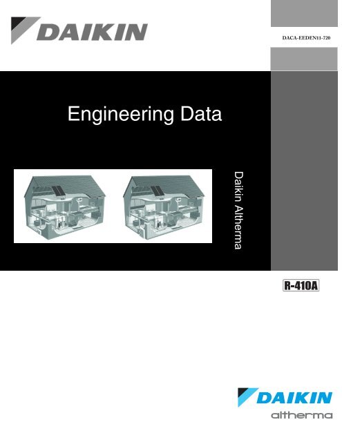
Engineering Data<br />
<strong>Daikin</strong> Altherma
D<strong>AC</strong>A-EEDEN11-720<br />
<strong>Daikin</strong> Altherma Engineering Data<br />
Part 1: Overview<br />
1. <strong>Daikin</strong> Altherma Overview .......................................................................... 1<br />
1.1 <strong>Daikin</strong> Altherma <strong>Split</strong> System ..........................................................................1<br />
1.2 <strong>Daikin</strong> Altherma <strong>Monobloc</strong> System .................................................................2<br />
1.3 System Configurations ...................................................................................3<br />
2. The Basics of <strong>Daikin</strong> Altherma ................................................................... 4<br />
2.1 Air-to-Water Heat Pump ..................................................................................4<br />
2.2 <strong>Split</strong> <strong>Type</strong> ........................................................................................................6<br />
2.3 <strong>Monobloc</strong> .........................................................................................................7<br />
3. Model Indentification................................................................................... 8<br />
3.1 Outdoor Units ..................................................................................................8<br />
3.2 Indoor Units .....................................................................................................8<br />
3.3 Options ............................................................................................................9<br />
4. System <strong>and</strong> Design Operation Recommendations.................................. 10<br />
5. Combination Overview ............................................................................ 12<br />
6. <strong>Split</strong> System Component Selection .......................................................... 13<br />
7. <strong>Monobloc</strong> Component Selection............................................................... 14<br />
Part 2: ERLQ018_024_030BAVJU <strong>Split</strong> <strong>Type</strong><br />
1. ERLQ - <strong>Split</strong> System Outdoor Unit ........................................................... 15<br />
1.1 Features ........................................................................................................15<br />
2. Specifications - <strong>Split</strong> System .................................................................... 16<br />
3. Capacity Tables - <strong>Split</strong> System................................................................. 19<br />
3.1 Heating ..........................................................................................................19<br />
3.2 Cooling .........................................................................................................20<br />
3.3 Altitude Correction .........................................................................................21<br />
4. Dimensional Drawing - <strong>Split</strong> System ........................................................ 22<br />
5. Center of Gravity - <strong>Split</strong> System ............................................................... 23<br />
6. Piping Diagram - <strong>Split</strong> System.................................................................. 24<br />
7. Wiring Diagram - <strong>Split</strong> Sytem ................................................................... 25<br />
8. Sound Data - <strong>Split</strong> System ....................................................................... 26<br />
9. Installation - <strong>Split</strong> System ......................................................................... 27<br />
9.1 Installation Location ......................................................................................27<br />
9.2 Installation Space .......................................................................................28<br />
10. Operation Range - <strong>Split</strong> System ............................................................. 29<br />
i
D<strong>AC</strong>A-EEDEN11-720<br />
Part 3: EKHB_030BA Hydrobox<br />
1. EKHB_030BA - Hydrobox ........................................................................ 30<br />
1.1 Features ........................................................................................................30<br />
2. Specifications - Hydrobox......................................................................... 31<br />
3. Dimensional Dwg. & Center of Gravity- Hydrobox ................................... 34<br />
4. Piping Diagram - Hydrobox ...................................................................... 35<br />
5. Wiring Diagram - Hydrobox ...................................................................... 36<br />
5.1 EKHB(H/X)030BA3VJU ................................................................................36<br />
5.2 EKHB(H/X)030BA6VJU ................................................................................37<br />
6. External Connection Diagram - Hydrobox ................................................ 38<br />
7. Condensate Instructions - Hydrobox ........................................................ 39<br />
8. Hydrobox Installation Precautions ............................................................ 40<br />
9. Application Examples - Hydrobox............................................................ 41<br />
10. Hydronic Performance - Hydrobox ........................................................ 45<br />
11. Operation Range - Hydrobox ................................................................. 46<br />
Part 2: ERLQ036_048_054BAVJU <strong>Split</strong> <strong>Type</strong><br />
1. ERLQ - <strong>Split</strong> System Outdoor Unit ........................................................... 47<br />
1.1 Features ........................................................................................................47<br />
2. Specifications - <strong>Split</strong> System .................................................................... 48<br />
3. Capacity Tables - <strong>Split</strong> System................................................................. 51<br />
3.1 Heating ..........................................................................................................51<br />
3.2 Cooling .........................................................................................................52<br />
3.3 Altitude Correction..........................................................................................53<br />
4. Dimensional Drawing - <strong>Split</strong> System ........................................................ 54<br />
5. Center of Gravity − <strong>Split</strong> System .............................................................. 55<br />
6. Piping Diagram - <strong>Split</strong> System.................................................................. 56<br />
7. Wiring Diagram - <strong>Split</strong> Sytem ................................................................... 57<br />
8. Sound Data - <strong>Split</strong> System ....................................................................... 58<br />
9. Installation - <strong>Split</strong> System ......................................................................... 59<br />
9.1 Installation Location ......................................................................................59<br />
9.2 Installation Space .......................................................................................60<br />
10. Operation Range - <strong>Split</strong> System ............................................................. 61<br />
Part 5: EKHB_054BA Hydrobox<br />
1. EKHB_054BA - Hydrobox ........................................................................ 62<br />
1.1 Features ........................................................................................................62<br />
2. Specifications - Hydrobox......................................................................... 63<br />
3. Dimensional Dwg. & Center of Gravity- Hydrobox ................................... 65<br />
4. Piping Diagram - Hydrobox ...................................................................... 66<br />
5. Wiring Diagram - Hydrobox ...................................................................... 67<br />
5.1 EKHB(H/X)054BA3VJU ................................................................................67<br />
5.2 EKHB(H/X)054BA6VJU ................................................................................68<br />
6. External Connection Diagram - Hydrobox ................................................ 69<br />
7. Condensate Instructions - Hydrobox ........................................................ 70<br />
8. Hydrobox Installation Precautions........................................................... 71<br />
9. Application Examples - Hydrobox............................................................. 72<br />
ii
D<strong>AC</strong>A-EEDEN11-720<br />
10. Hydronic Performance - Hydrobox ........................................................ 76<br />
11. Operation Range - Hydrobox ................................................................. 77<br />
Part 6: EDLQ / EBLQ_036_048_054 <strong>Monobloc</strong><br />
1. <strong>Monobloc</strong> - EDLQ / EBLQ ........................................................................ 78<br />
1.1 Features ........................................................................................................78<br />
2. Specifications − EDLQ − Heat Only ......................................................... 79<br />
3. Capacity Tables − EDLQ − Heat Only ...................................................... 83<br />
4. Specifications − EBLQ Heat Pump........................................................... 84<br />
5. Capacity Tables − EBLQ − Heating.......................................................... 88<br />
6. Capacity Tables − EBLQ − Cooling .......................................................... 89<br />
6.1 Altitude Correction 90<br />
7. Dimensional Drwg. & Center of Gravity - <strong>Monobloc</strong> ................................. 91<br />
8. Piping Diagram - <strong>Monobloc</strong> ..................................................................... 92<br />
9. Wiring Diagram - <strong>Monobloc</strong> ...................................................................... 93<br />
9.1 Wiring Diagram .............................................................................................94<br />
9.2 External Connection Diagram - <strong>Monobloc</strong> ....................................................95<br />
10. Sound Data - <strong>Monobloc</strong>.......................................................................... 96<br />
10.1 Sound Pressure Spectrum - Normal Operation ..........................................96<br />
10.2 Sound Pressure Night Quiet Mode .............................................................96<br />
11. Application Examples - <strong>Monobloc</strong> .......................................................... 97<br />
12. Installation - <strong>Monobloc</strong>.......................................................................... 102<br />
12.1 Installation Location ..................................................................................102<br />
12.2 Installation Space .....................................................................................103<br />
13. Hydronic Performance - <strong>Monobloc</strong> ....................................................... 104<br />
14. Glycol Correction Factors-Power Input & Capacity .............................. 105<br />
15. Glycol Correction Factors - Flow Rate & Pressure Drop ..................... 106<br />
16. Operation Range - <strong>Monobloc</strong> ............................................................... 107<br />
Part 7: EKHWS050_080BA3VJU Domestic Hot Water<br />
1. Domestic Hot Water Tank ...................................................................... 108<br />
1.1 Features ......................................................................................................108<br />
2. Specifications - DHW.............................................................................. 109<br />
3. Domestic Hot Water Basic Performance Overview ................................ 110<br />
4. Dimensional Drawing & Center of Gravity - DHW ................................. 111<br />
4.1 Domestic Hot Water Tank Summary ...........................................................112<br />
5. Three-Way Valve Summary .................................................................. 113<br />
Part 8: Options<br />
1. Solar Kit (EKSOLHWBAVJU) ................................................................. 115<br />
1.1 Features .....................................................................................................115<br />
1.2 Specifications − Solar Kit ............................................................................116<br />
1.3 Dimensional Drwg. & Center of Gravity - Solar Kit ......................................117<br />
1.4 Piping Diagram - Solar Kit ...........................................................................118<br />
1.5 Wiring Diagram - Solar Kit ...........................................................................119<br />
2. Room Thermostat − EKRTWA .............................................................. 120<br />
2.1 Specifications - Room Thermostat ............................................................121<br />
2.2 Dimensions - Room Thermostat ................................................................122<br />
iii
D<strong>AC</strong>A-EEDEN11-720<br />
2.3 Application Example - Room Thermostat ....................................................123<br />
2.4 Wiring Connection - Room Thermostat .......................................................124<br />
2.5 User Display - Room Thermostat ................................................................125<br />
2.6 Functional Summary - Room Thermostat ...................................................126<br />
3. Condensate Kit − EKHBDP .................................................................... 127<br />
4. Digital I/O PCB Kit − EKRP1HBAAU ...................................................... 128<br />
5. DHW Kit Option - D<strong>AC</strong>A - DHW Kit -1.................................................... 129<br />
6. BSP to NPT Adaptor Kits........................................................................ 131<br />
Part 9: Field Setting Overview / Appendix<br />
1. Field Setting Overview............................................................................ 135<br />
iv
D<strong>AC</strong>A-EEDEN11-720<br />
<strong>Daikin</strong> Altherma Overview<br />
1. <strong>Daikin</strong> Altherma Overview<br />
1.1 <strong>Daikin</strong> Altherma <strong>Split</strong> System<br />
<strong>Daikin</strong> Altherma is a Total Comfort air-to-water heat pump system that utilizes an outdoor R-410A heat<br />
pump system, with Inverter controlled compressor, to extract heat from the outdoor air <strong>and</strong> transfers this<br />
heat through refrigerant piping to a refrigerant-to-water cupro-nickel brazed plate heat exchanger in the<br />
hydrobox (indoor unit on split system <strong>and</strong> incorporated in the outdoor unit on the monobloc). The hydrobox<br />
circulates the heated water through low temperature heat emitters (low temperature radiators, floor heating<br />
systems <strong>and</strong> fan coil units) <strong>and</strong> also provides domestic hot water (DHW) with the optional DHW tank (316L<br />
stainless steel heat exchanger <strong>and</strong> tank). The heat pump version of the hydrobox can reverse the cycle<br />
<strong>and</strong> provide chilled water for cooling through fan coil units (fan coil units for cooling are field supplied <strong>and</strong><br />
must have a condensate drain pan). <strong>Daikin</strong> Altherma can heat spaces, produces domestic hot water <strong>and</strong><br />
with the heat pump version hydrobox or monobloc can cool spaces.<br />
The high coefficient of performance (COP) of the <strong>Daikin</strong> Altherma heat pump is largely attributed to the<br />
<strong>Daikin</strong> inverter principle. An integrated frequency converter adjusts the rotational speed of the compressor<br />
to suit the heating (cooling) dem<strong>and</strong>. The system seldom operates at full capacity <strong>and</strong> maximizes<br />
efficiency by controlling the compressor rpm.<br />
<strong>Daikin</strong> Altherma Overview 1
D<strong>AC</strong>A-EEDEN11-720<br />
<strong>Daikin</strong> Altherma Overview<br />
1.2 <strong>Daikin</strong> Altherma <strong>Monobloc</strong> System<br />
Design Considerations:<br />
Minimum water volume : 5.3 gallons<br />
Heat Exchanger never exceeds 121°F (55°C)<br />
Maximum water temperature: 149°F (65°C)<br />
Maximum water pressure: 43.5 psi (3 bar)<br />
NOTE: Never set the target leaving-water temperature setpoint on boiler controller: 131°F (55°C)<br />
2 <strong>Daikin</strong> Altherma Overview
D<strong>AC</strong>A-EEDEN11-720<br />
<strong>Daikin</strong> Altherma Overview<br />
1.3 System Configurations<br />
Selection Conditions<br />
Typical conditions for the heating LWT are:<br />
86 to 95° F (at design conditions) for floor heating<br />
86 to 113° F (at design conditions) for fan coil units<br />
104 to 122° F (at design conditions) for low temperature radiators<br />
<strong>Daikin</strong> Altherma Overview 3
D<strong>AC</strong>A-EEDEN11-720<br />
The Basics of <strong>Daikin</strong> Altherma<br />
2. The Basics of <strong>Daikin</strong> Altherma<br />
2.1 Air-to-Water Heat Pump<br />
4 The Basics of <strong>Daikin</strong> Altherma
D<strong>AC</strong>A-EEDEN11-720<br />
The Basics of <strong>Daikin</strong> Altherma<br />
<br />
The Basics of <strong>Daikin</strong> Altherma 5
D<strong>AC</strong>A-EEDEN11-720<br />
The Basics of <strong>Daikin</strong> Altherma<br />
2.2 <strong>Split</strong> <strong>Type</strong><br />
<br />
6 The Basics of <strong>Daikin</strong> Altherma
D<strong>AC</strong>A-EEDEN11-720<br />
The Basics of <strong>Daikin</strong> Altherma<br />
2.3 <strong>Monobloc</strong><br />
The Basics of <strong>Daikin</strong> Altherma 7
D<strong>AC</strong>A-EEDEN11-720<br />
Model Indentification<br />
3. Model Indentification<br />
3.1 Outdoor Units<br />
3.2 Indoor Units<br />
8 Model Indentification
D<strong>AC</strong>A-EEDEN11-720<br />
Model Indentification<br />
3.3 Options<br />
Model Indentification 9
D<strong>AC</strong>A-EEDEN11-720<br />
System <strong>and</strong> Design Operation Recommendations<br />
4. System <strong>and</strong> Design Operation Recommendations<br />
Three (3) steps for a good design:<br />
1. Accurate calculations of heat losses (transmission <strong>and</strong> ventilation losses).<br />
2. Selection of <strong>Daikin</strong> Altherma based on heat loss calculation <strong>and</strong> preferably for low water temperature<br />
application (95°F/35°C to 104°F/40°C). Use the available <strong>Daikin</strong> Altherma selection <strong>and</strong> software tools.<br />
3. Selection of heat emitters should be based on design ΔT of 9°F/5°C for optimum efficiency <strong>and</strong> capacity.<br />
The actual heat emitter ΔT can be designed between 5°F/3°C to 14°F/8°C. The circulator in the<br />
hydrobox section has a three speed motor <strong>and</strong> is factory set on high speed; remember to match the<br />
circulator speed with the required system flow (lower circulator speed can be selected at lower flow<br />
<strong>and</strong> head). If the system flow exceeds 12 gpm @ approximately 10 feet of head, a primary/secondary<br />
hydronic piping system is recommended.<br />
Design hint: If the heat losses exceed the single total Altherma capacity at design ambient conditions,<br />
multiple Altherma systems may be used in unison to aid greater DHW consumption or larger heating loads<br />
in single zones. For multiple zones it is highly recommended to utilize multiple (separate) systems. <strong>Daikin</strong><br />
Altherma can also be applied using an auxiliary boiler connected in parallel (Bi-Valent application)<br />
Recommended Altherma leaving water temperature (LWT) selections conditions:<br />
86°F/30°C to 95°F/35°C (at design conditions) for floor heating<br />
86°F/30°C to 113°F/45°C (at design conditions) for fan coil units<br />
104°F/40°C to 122°F/50°C (at design conditions) for low temperature radiators<br />
Operating the System:<br />
To get the most comfort with the lowest energy consumption with <strong>Daikin</strong> Altherma, it is very important to<br />
observe the following items:<br />
• Define possible schedule timer actions for each day by filling out the form at the end of the operation<br />
manual can help minimize energy consumption.<br />
• Make sure the heat pump system works at the lowest possible hot water temperature to heat the home.<br />
To optimize this, make sure the weather dependent set point (outdoor reset) is used <strong>and</strong> configured to<br />
match the installation environment (use the available selection <strong>and</strong> software tool).<br />
Next recommendations apply to installations with an optional domestic hot water (DHW) tank:<br />
• Make sure the DHW is only heated up to the hot water temperature required.<br />
• Optimize the scheduling of DHW operation of the Altherma system so that DHW is heated via the system<br />
1-2hrs prior to the DHW being required (refer to the schedule timer function <strong>and</strong> programming<br />
explained in the users operation manual<br />
10 System <strong>and</strong> Design Operation Recommendations
D<strong>AC</strong>A-EEDEN11-720<br />
System <strong>and</strong> Design Operation Recommendations<br />
Quote #:<br />
Job Name:<br />
Customer:<br />
Contact:<br />
<strong>Daikin</strong> Altherma Checklist<br />
Low Temperature Model<br />
Date:<br />
Required by:<br />
PO:<br />
A) Sizing Information: Outdoor Temperature Where Heat Loss = Zero: ________ Night Setback Temperature: __________<br />
Outdoor Temperature Where Cooling load = Zero: ________<br />
Heat Loss: _______________ Btu/h Heating Months: _________________ Cooling Months: _________________<br />
Heat Gain (if cooling): __________________Btu/h<br />
Total Area: __________________ Square Feet<br />
Energy Cost: Electricity_____kW; Gas_____Therm; Oil____gal Peak / St<strong>and</strong>ard Dem<strong>and</strong> Charge Period: ______________<br />
Details:<br />
B) System Selection:<br />
System Layout:<br />
<strong>Split</strong> System-Small Capacity (018,024,030) <strong>Split</strong> System-Large Capacity (036,048,054) <strong>Monobloc</strong> (packaged unit)<br />
(R410A piping to indoor hydrobox) (R410A piping to indoor hydrobox) (H 2 O piping to inside) (6kW 2-stg backup heater)<br />
System <strong>Type</strong>:<br />
Backup heater selection is not applicable to <strong>Monobloc</strong><br />
Heating Only Heat Pump (Heating & Cooling) 3 kW 6kW<br />
EKHBH-<strong>Split</strong> System / EDLQ-<strong>Monobloc</strong> EKHBX-<strong>Split</strong> System / EBLQ-<strong>Monobloc</strong> Backup heat cap. Backup heat cap. 2-stage<br />
System Criteria:<br />
Heating (LWT _______°F/°C) Cooling (LWT _______°F/°C) DHW (Water Temp _______°F/°C)<br />
(Maximum temperature 131°F / 55°C)<br />
(EKBDHP Condensate Kit Required)<br />
System Source:<br />
100% Heat Pump Heat Pump w/Electric Heater Heat Pump with Auxiliary Boiler<br />
(Mono-Valent) (Mono-Energetic) (Bi-Valent)<br />
Heat Emitters:<br />
Dual Setpoint Temperature:______high______low<br />
<strong>Type</strong> Heat or Cool Capacity Btu/h CFM-Fan Coil<br />
Radiant Floor<br />
86 to 95°F / 30 to 35°C<br />
Fan Coil<br />
86 to 113°F / 30 to 45°C<br />
Low Temp Radiators<br />
104 to 122°F / 40 to 50°C<br />
Domestic Hot Water:<br />
50 Gallon 80 Gallon<br />
D<strong>AC</strong>A-DHWKIT-1 Optional Solar Kit<br />
(Integrated 3kW booster heater) (Optional DHW Connection Kit) (Connection kit to storage tank only)<br />
Option:<br />
I/O Control Board Interface (PCB)<br />
BSP to NPT Adaptor:<br />
Hydrobox Inlet/Outlet 3-Way Valve DHW Tank Inlet / Outlet<br />
D<strong>AC</strong>A-HBA-1: 1-1/4"(F)BSPT X 1-1/4"(M)NPT D<strong>AC</strong>A-3WVTH-1: 1"(M)BSPT X 1"(F)NPT D<strong>AC</strong>A-THXA-1: 3/4"(M)BSPP X 3/4"(F)NPT<br />
D<strong>AC</strong>A-HBA-2: 1"(F)BSPT X 1"(M)NPT D<strong>AC</strong>A-3WVTA-1: 1"(M)BSPT X 1-1/4"(F)NPT Water Inlet / Outlet<br />
D<strong>AC</strong>A-HBA-3: 1-1/4"(M)BSPP X 1-1/4"(M)NPT<br />
D<strong>AC</strong>A-DHWTA-1: 3/4"(M)BSPT X 3/4"(F)NPT<br />
Thermostats:<br />
<strong>Daikin</strong> Thermostat (EKRTWA) Zone Thermostats (by others)<br />
(Wired to hydro box)<br />
Notes:<br />
Additional Heat EmitterSpecifications<br />
Room Thermostat (by others)<br />
(Wired to hydro box) Must have 6min. run time<br />
Version 2 (2011)<br />
System <strong>and</strong> Design Operation Recommendations 11
D<strong>AC</strong>A-EEDEN11-720<br />
Combination Overview<br />
5. Combination Overview<br />
<strong>Daikin</strong> Altherma <strong>Split</strong> System<br />
Hydrobox Heating Only Hydrobox Heat Pump (Reversible)<br />
Hydrobox Heating Only Hydrobox Heat Pump (Reversible)<br />
Combination Overview<br />
EKHBH030BA3VJU EKHBH030BA6VJU EKHBX030BA3VJU EKHBX030BA6VJU EKHBH054BA3VJU EKHBH054BA6VJU EKHBX054BA3VJU EKHBX054BA6VJU<br />
ERLQ0BAVJU X X X X<br />
ERLQ0BAVJU X X X X<br />
ERLQ0BAVJU X X X X<br />
Outdoor Unit<br />
ERLQ036BAVJU X X X X<br />
ERLQ048BAVJU X X X X<br />
ERLQ054BAVJU X X X X<br />
DHW Tank (50 gal) EKHWS050BA3VJU X X X X X X X X<br />
DHW Tank (80 gal) EKHWS080BA3VJU X X X X X X X X<br />
Digital I/O PCB EKRP1HBAAU 1 1 1 1 1 1 1 1<br />
Solar Pump Kit EKSOLHWBAVJU 2 2 2 2 2 2 2 2<br />
Wired Thermostat EKRTWA X X X X X X X X<br />
Condensate Kit EKHBDP N/A N/A 3 3 N/A N/A 3 3<br />
<strong>Daikin</strong> Altherma <strong>Monobloc</strong><br />
Combination Overview<br />
<strong>Monobloc</strong> Heating Only <strong>Monobloc</strong> Heat Pump (Reversible)<br />
EDLQ036BA6VJU EDLQ048BA6VJU EDLQ054BA6VJU EBLQ036BA6VJU EBLQ048BA6VJU EBLQ054BA6VJU<br />
DHW Tank (50 gal) EKHWS050BA3VJU X X X X X X<br />
DHW Tank (80 gal) EKHWS080BA3VJU X X X X X X<br />
Digital I/O PCB EKRP1HBAAU 1 1 1 1 1 1<br />
Solar Pump Kit EKSOLHWBAVJU 2 2 2 2 2 2<br />
Wired Thermostat EKRTWA X X X X X X<br />
Condensate Kit EKHBDP N/A N/A N/A N/A N/A N/A<br />
Notes:<br />
X - Can be applied<br />
1 - Applied with Solar Pump Kit (DHW solar priority); alarm output; Bi-Valent operation (auxiliary boiler)<br />
2 - Can be applied with DHW Tank (thermal solar panels <strong>and</strong> pump station to be field supplied)<br />
3 - Must be applied with Heat Pump Hydrobox<br />
12 Combination Overview
D<strong>AC</strong>A-EEDEN11-720<br />
<strong>Split</strong> System Component Selection<br />
6. <strong>Split</strong> System Component Selection<br />
<strong>Daikin</strong> Altherma <strong>Split</strong> System Component Selection (All Outdoor units have base pan heater)<br />
<strong>Daikin</strong> Altherma<br />
System Selection<br />
from Checklist<br />
Size Selection of<br />
<strong>Daikin</strong> Altherma<br />
Based on Heat Loss<br />
<strong>Daikin</strong> Altherma<br />
Options from<br />
Checklist<br />
Heating<br />
Only<br />
<strong>and</strong>/or<br />
DHW<br />
Yes<br />
ERLQ018<br />
ERLQ024<br />
ERLQ030<br />
ERLQ036<br />
ERLQ048<br />
ERLQ054<br />
EKHBH030BA3<br />
EKHBH030BA6<br />
EKHBH054BA3<br />
EKHBH054BA6<br />
(3=3 kW; 6=6 kW Backup<br />
Indoor Unit<br />
No<br />
Outdoor<br />
Unit<br />
Size Selection of<br />
<strong>Daikin</strong> Altherma<br />
Based on Heat Loss<br />
<strong>Daikin</strong> Altherma<br />
Options from<br />
Checklist<br />
Heating,<br />
Cooling<br />
<strong>and</strong>/or<br />
DHW<br />
Yes<br />
ERLQ018<br />
ERLQ024<br />
ERLQ030<br />
ERLQ036<br />
ERLQ048<br />
ERLQ054<br />
Outdoor<br />
Unit Indoor Unit<br />
EKHBX030BA3<br />
EKHBX030BA6<br />
EKHBX054BA3<br />
EKHBX054BA6<br />
(3=3 kW; 6=6 kW Backup<br />
Heater)<br />
EKHWS050BA3 (50 gal)<br />
EKHWS080BA3 (80 gal)<br />
Both DHW Tanks Have<br />
3 kW Booster Heater<br />
DHW Solar Option<br />
EKSOLHWBA<br />
EKRTWA<br />
Wired Room<br />
Thermostat<br />
EKRP1HBAAU<br />
Digital I/O PCB<br />
EKHBDP<br />
Condensate Kit<br />
EKHWS050BA3 (50 gal)<br />
EKHWS080BA3 (80 gal)<br />
Both DHW Tanks have 3<br />
kW Booster Heater<br />
DHW Solar Option<br />
EKSOLHWBA<br />
EKRTWA<br />
Wired Room<br />
Thermostat<br />
EKRP1HBAAU<br />
Digital I/O PCB<br />
<strong>Split</strong> System Component Selection 13
D<strong>AC</strong>A-EEDEN11-720<br />
<strong>Monobloc</strong> Component Selection<br />
7. <strong>Monobloc</strong> Component Selection<br />
<strong>Daikin</strong> Altherma <strong>Monobloc</strong> System Component Selection (All monobloc units have base pan heater)<br />
<strong>Daikin</strong> Altherma<br />
System Selection<br />
from Checklist<br />
Size Selection of<br />
<strong>Daikin</strong> Altherma<br />
Based on Heat Loss<br />
<strong>Daikin</strong> Altherma<br />
Options from<br />
Checklist<br />
EKHWS050BA3 (50 gal)<br />
EKHWS080BA3 (80 gal)<br />
Both DHW Tanks Have<br />
3 kW Booster Heater<br />
Heating<br />
Only<br />
<strong>and</strong>/or<br />
DHW<br />
Yes<br />
EDLQ036BA6VJU (all monobloc units have<br />
EDLQ048BA6VJU 6 kW backup heater)<br />
EDLQ054BA6VJU<br />
DHW Solar Option<br />
EKSOLHWBA<br />
No<br />
<strong>Monobloc</strong> Units<br />
EKRTWA<br />
Wired Room<br />
Thermostat<br />
EKRP1HBAAU<br />
Digital I/O PCB<br />
Size Selection of<br />
<strong>Daikin</strong> Altherma<br />
Based on Heat Loss<br />
<strong>Daikin</strong> Altherma<br />
Options from<br />
Checklist<br />
EKHWS050BA3 (50 gal)<br />
EKHWS080BA3 (80 gal)<br />
Both DHW Tanks Have<br />
3 kW Booster Heater<br />
Heating,<br />
Cooling<br />
<strong>and</strong>/or<br />
DHW<br />
Yes<br />
EBLQ036BA6VJU (all monobloc units have<br />
EBLQ048BA6VJU 6 kW backup heater)<br />
EBLQ054BA6VJU<br />
<strong>Monobloc</strong> Units<br />
DHW Solar Option<br />
EKSOLHWBA<br />
EKRTWA<br />
Wired Room<br />
Thermostat<br />
EKRP1HBAAU<br />
Digital I/O PCB<br />
14 <strong>Monobloc</strong> Component Selection
D<strong>AC</strong>A-EEDEN11-720<br />
ERLQ - <strong>Split</strong> System Outdoor Unit<br />
1. ERLQ - <strong>Split</strong> System Outdoor Unit<br />
1.1 Features<br />
• Inverter operated compressor<br />
• Single phase large capacity outdoor unit (018, 024, 030)<br />
• Cost effective alternative to a fossil fuel boiler<br />
• Low energy bills <strong>and</strong> low CO2 emissions<br />
• Easy to install<br />
• Total solution for year round comfort<br />
• Anti-corrosion treatment on outdoor coil<br />
• Bottom base pan heater to improve water drainage during defrost<br />
• Excellent solution for multi-family applications requiring heating, cooling, <strong>and</strong> DHW.<br />
ERLQ outdoor units are combined with an indoor hydrobox; a heating-only hydrobox version (EKHBH), <strong>and</strong> a heat<br />
pump (heating & cooling) hydrobox version (EKHBX). Both hydrobox versions can be applied with an optional<br />
domestic hot water tank (EKHWS) <strong>and</strong> optional solar pump kit (EKSOLHW)<br />
ERLQ - <strong>Split</strong> System Outdoor Unit 15
D<strong>AC</strong>A-EEDEN11-720<br />
Specifications - <strong>Split</strong> System<br />
2. Specifications - <strong>Split</strong> System<br />
2-1 NOMINAL CAP<strong>AC</strong>ITY AND NOMINAL<br />
INPUT ERLQ018BAVJU ERLQ024BAVJU ERLQ030BAVJU<br />
For<br />
combination<br />
indoor units +<br />
outdoor units<br />
Indoor Units<br />
EKHBH030BA<br />
(Heating Only)<br />
Condition<br />
(Floor Heating)<br />
Condition 2<br />
(Fan Coil)<br />
For<br />
combination<br />
indoor units +<br />
outdoor units<br />
Condition 1<br />
(Floor Heating)<br />
Condition 2<br />
(Fan Coil)<br />
Heating Nominal kBTU/hr (kW) 19.62 (5.75) 23.34 (6.84) 28.76 (8.43)<br />
capacity<br />
Heating PI Nominal kBTU/hr (kW) 4.61 (1.35) 5.66 (1.66) 7.54 (2.21)<br />
COP Nominal 4.24 4.12 3.81<br />
Heating Nominal kBTU/hr (kW) 17.16 (5.03) 20.81 (6.1) 26.07 (7.64)<br />
capacity<br />
Heating PI Nominal kBTU/hr (kW) 5.66 (1.66) 6.96 (2.04) 9.11 (2.67)<br />
COP Nominal 3.03 2.99 2.86<br />
Indoor Units EKHBX030BA<br />
(Reversible)<br />
Heating Nominal kBTU/hr (kW) 19.62 (5.75) 23.34 (6.84) 28.76 (8.43)<br />
capacity<br />
Cooling Nominal kBTU/hr (kW) 24.57(7.2) 27.84 (8.16) 28.56 (8.37)<br />
capacity<br />
Heating PI Nominal (kW) 1.35 1.66) 2.21<br />
Cooling PI Nominal kW 2.36 2.87 3.06<br />
COP Nominal 4.25 4.12 3.81<br />
EER Nominal -- 10.41 9.70 9.33<br />
Heating Nominal kBTU/hr (kW) 17.16 (5.03) 20.81 (6.1) 26.07 (7.64)<br />
capacity<br />
Cooling Nominal kBTU/hr (kW) 17.47 (5.12) 20.0 (5.86) 20.75 (6.08)<br />
capacity<br />
Heating PI Nominal (kW) 1.66 2.04 2.67<br />
Cooling PI Nominal (kW) 2.25 2.68 2.84<br />
COP Nominal 3.03 2.99 2.86<br />
EER Nominal 7.76 7.46 7.30<br />
Notes Condition 1: cooling Ta 95°F (35°C) - LWE 64.4°F (18°C) - heating Ta DB/WB 44.6/42.8°F (7/6°C - LWC 95°F<br />
(35°C) ( ΔT = 9°F (5°C )<br />
Condition 2: cooling Ta 95°F (35°C) - LWE 45°F (7°C) (ΔT = 9°F (5°C ) - heating Ta DB/WB 44.6/42.8°F (7/6°C)<br />
- LWC 113°F (45°C) ( ΔT = 9°F (5°C )<br />
2-2 TECHNICAL SPECIFICATIONS ERLQ018BAVJU ERLQ024BAVJU ERLQ030BAVJU<br />
Casing Colour Ivory white<br />
Material <br />
Dimensions Unit Height in (mm) 28.9 (735)<br />
Width in (mm) 32.5 (825)<br />
Depth in (mm) 11.8 (300)<br />
Packing Height in (mm) 31.4 (797)<br />
Width in (mm) 37.8 390)<br />
Depth in (mm) 15.4 (390)<br />
Weight Unit lb (kg) 126 (57)<br />
Packed Unit lb (kg) 137 (62)<br />
Packing Material EPS, CARTON<br />
Carton<br />
Wood<br />
PP (Straps)<br />
Weight lb (kg) 11 (5)<br />
16 Specifications - <strong>Split</strong> System
D<strong>AC</strong>A-EEDEN11-720<br />
Specifications - <strong>Split</strong> System<br />
2-2 TECHNICAL SPECIFICATIONS ERLQ018BAVJU ERLQ024BAVJU ERLQ030BAVJU<br />
Heat<br />
Dimensions Length in (mm) 33-1/3” (845 mm) 33-1/3” (845 mm) 33-1/3” (845 mm)<br />
Exchanger<br />
Nr of Rows 2 2 2<br />
Fin Pitch in (mm) 0.07” (1.8 mm) 0.07” (1.8 mm) 0.07” (1.8 mm)<br />
Nr of Passes - - -<br />
Face Area ft² (m²) 3.22 ft² (0.98 m²) 3.22 ft² (0.98 m²) 3.22 ft² (0.98 m²)<br />
# of Stages 32 32 32<br />
Tube type<br />
Hi-XSS(8)<br />
Fin <strong>Type</strong> WF fin<br />
Treatment<br />
Anti-corrosion treatment (PE)<br />
Fan <strong>Type</strong> Propeller<br />
Quantity 1 1 1<br />
Air Flow Rate Heating High cfm (m³/min) - - -<br />
(nominal at Cooling High cfm (m³/min) - - -<br />
230V)<br />
Fan Discharge direction Horizontal<br />
Motor Quantity 1<br />
Model<br />
Brushless DC motor<br />
Motor Speed (nominal) Steps - - -<br />
Heating rpm - - -<br />
Cooling rpm - - -<br />
Fan Motor Output W 53 53 53<br />
Drive<br />
Direct drive<br />
Compressor Quantity 1<br />
Motor Model 2YC63BXD#C<br />
<strong>Type</strong><br />
<br />
Motor Output W 1920<br />
Starting Method<br />
Inverter driven<br />
Ambient Heating Min °F (°C) 5 (-15)<br />
Operation<br />
Max °F (°C) 77 (25)<br />
Range<br />
Cooling Min °F (°C) 50 (10)<br />
Max °F (°C) 109 (43)<br />
Domestic Hot Water Min °F (°C) 5 (-15) 5 (-15) 5 (-15)<br />
Max °F (°C) 109.4 (43)<br />
109.4 (43)<br />
109.4 (43)<br />
95 (35) HP / 109.4 (43) BH 95 (35) HP / 109.4 (43) BH) 95 (35) HP / 109.4 (43) BH<br />
Sound Level Heating Sound Power dBA 61 61 62<br />
(nominal) *1<br />
Sound Pressure dBA 48 48 49<br />
Cooling Sound Power dBA 63 63 63<br />
Sound Pressure dBA 48 48 50<br />
Sound Level Heating Sound Pressure dBA - - -<br />
(Night quiet) Cooling Sound Pressure dBA - - -<br />
Refrigerant <strong>Type</strong> <br />
Charge lbs (kg) 3.7 (1.7)<br />
Control<br />
Expansion valve(electronic type)<br />
Nr of Circuits 1<br />
Refrigerant Oil <strong>Type</strong> <br />
Charged Volume GAL (l) 0.20 (0.75)<br />
Specifications - <strong>Split</strong> System 17
D<strong>AC</strong>A-EEDEN11-720<br />
Specifications - <strong>Split</strong> System<br />
2-2 TECHNICAL SPECIFICATIONS ERLQ018BAVJU ERLQ024BAVJU ERLQ030BAVJU<br />
Piping<br />
Liquid (OD) Quantity 1<br />
connections<br />
<strong>Type</strong><br />
Flare connection<br />
Diameter (OD) in (mm) 1/4 (6.35)<br />
Gas Quantity 1<br />
<strong>Type</strong><br />
Flare connection<br />
Diameter (OD) in (mm) 5/8” (15.9 mm)<br />
Drain Quantity 1<br />
<strong>Type</strong><br />
Hole<br />
Diameter (OD) in (mm) 0.79 (20)<br />
Piping Length Minimum ft (m) 9.8 (3)<br />
Maximum ft (m) 98 (30)<br />
Equivalent ft (m) --<br />
Chargeless ft (m) 32.8 (10)<br />
Additional Refrigerant Charge kg See installation manual outdoor unit<br />
Installation height Maximum ft (m) 66 (20)<br />
difference<br />
Heat Insulation<br />
<br />
Defrost Method<br />
Pressure equalizing<br />
Defrost Control<br />
Sensor for outdoor heat exchanger temperature<br />
Capacity Control Method<br />
Inverter controlled<br />
Safety Devices<br />
Fan motor thermal protector<br />
Fuse<br />
High pressure switch<br />
St<strong>and</strong>ard Item<br />
Installation Manual<br />
Accessories<br />
Quantity 1<br />
(*1) The sound pressure level is measured via a microphone at a certain distance from the unit. It is a<br />
relative value depending on the distance <strong>and</strong> acoustic environment. Refer to sound spectrum<br />
Notes<br />
drawing for more information.<br />
(*2) Down to 10 ft. (3 m) with recharging of the outdoor unit. Refer to the installation manual of<br />
the outdoor unit.<br />
2-3 ELECTRICAL SPECIFICATIONS ERLQ018BAVJU ERLQ024BAVJU ERLQ030BAVJU<br />
Power Supply Name VJU<br />
Phase 1~<br />
Frequency Hz 60<br />
Voltage V 208-230<br />
Voltage range Minimum V 187<br />
Maximum V 253<br />
Current Compressor Rated Load Amps (RLA) A 17.5<br />
Total Full Load Amps (FLA) A 18<br />
Minimum Circuit Amps (MCA) A 18<br />
Maximum Overcurrent<br />
A 20<br />
Protection (MOP)<br />
Wiring For Power<br />
Remark<br />
See installation manual outdoor unit<br />
Connections Supply<br />
For Connection<br />
Remark<br />
See installation manual outdoor unit<br />
with Indoor<br />
Power Supply Intake<br />
Outdoor Unit Only<br />
Notes St<strong>and</strong>ard for Safety Heating <strong>and</strong> Cooling Equipment; UL1995/CSA (U&C) C22.2 #236.<br />
18 Specifications - <strong>Split</strong> System
D<strong>AC</strong>A-EEDEN11-720<br />
Capacity Tables - <strong>Split</strong> System<br />
3. Capacity Tables - <strong>Split</strong> System<br />
3.1 Heating<br />
Peak value does not include capacity drop during frosting <strong>and</strong> defrosting periods.<br />
Integrated value takes into consideration the capacity drop during frosting <strong>and</strong> defrosting periods.<br />
Capacity Tables - <strong>Split</strong> System 19
D<strong>AC</strong>A-EEDEN11-720<br />
Capacity Tables - <strong>Split</strong> System<br />
3.2 Cooling<br />
Symbols:<br />
CC Cooling Capacity @ maximum operating frequency, BTU/h<br />
HC Heating Capacity @ maximum operating frequency, BTU/h<br />
PI Cooling Power Input (kW), Heating Power Input (kBTU/h measured according to Eurovent 6/C003-2006 (kW)/EN14511<br />
LWE Leaving Water evaporator temperature (Cooling)<br />
LWC Leaving Water condenser temperature (Heating)<br />
Tamb Outdoor Ambient temperature, RH = 85%<br />
Conditions:<br />
Cooling Capacity BTU/h <strong>and</strong> valid for chilled water range ΔT = 5-15 0 F (3-8 0 C)<br />
Heating Capacity is according to Eurovent 6/C/003-2006 (kW) <strong>and</strong> valid for heating water range ΔT = 5-15 0 F (3-8 0 C)<br />
Power Input is total of indoor <strong>and</strong> outdoor unit, except the circulation pump; (90W per EN14511)<br />
20 Capacity Tables - <strong>Split</strong> System
D<strong>AC</strong>A-EEDEN11-720<br />
Capacity Tables - <strong>Split</strong> System<br />
3.3 Altitude Correction<br />
Capacity Correction Factor- due to lower air density<br />
ALTITUDE DENSITY<br />
CAP<strong>AC</strong>ITY<br />
RATIO<br />
(ft) (m) (lb/ft 3 ) (kg/m 3 ) (%)<br />
0 0 0.0807 1.293 100<br />
1,000 305 0.7785 1.247 98<br />
2,000 610 0.075 1.202 96<br />
5,000 1,524 0.0672 1.076 90<br />
7,500 2,286 0.0611 0.979 85<br />
10,000 3,048 0.0555 0.889 81<br />
Altitude Influence on <strong>Daikin</strong> Altherma Operation Range<br />
Altitude<br />
Ambient<br />
Temperature<br />
Absolute<br />
Atmospheric<br />
(ft) (m) (°F) (°C) (bar) (psi)<br />
Taking this influence into consideration, it is recommended to design your <strong>Daikin</strong> Altherma system, with a<br />
target leaving water temperature 2°F (1°C) below the maximum permitted set-point of 122°F (50°C).<br />
Considerations for project designs in high altitude conditions<br />
Absolute Pressure<br />
40 bar<br />
(G)<br />
580.15<br />
psi<br />
1. Determine the altitude at the location the <strong>Daikin</strong> Altherma system is being considered for.<br />
2. Verify the altitude correction factor from the table enclosed in this bulletin.<br />
3. If an altitude falls within specified values, use the correction graph to determine the applicable capacity<br />
correction factor.<br />
4. Since the <strong>Daikin</strong> Altherma selection <strong>and</strong> simulator software does not correct for altitude, add the altitude<br />
correction factor to the load requirements before the initial selection is made.<br />
5. Conduct the equipment selection based on these conditions as per normal procedures.<br />
Example: -<br />
A <strong>Daikin</strong> Altherma system is being considered for an application in Denver, CO.<br />
Denver is located at an altitude of 5,000ft, thus the capacity correction factor would be 10%.<br />
R410A Condition<br />
If the load calculations determined a 40,000 Btu/hr requirement, adding the correction factor for altitude<br />
would result in 40,000 Btu/hr + 10% (4,000 Btu/hr), thus the load required for the selection of <strong>Daikin</strong><br />
Altherma would be 44,000 Btu/hr.<br />
Temp<br />
(°F)<br />
0 0 59 15 1.013 14.7 38.99 565.45 143.87 62.15<br />
1,000 305 59 15 0.977 14.17 39.02 565.98 143.94 62.19<br />
2,000 610 59 15 0.942 13.66 39.06 566.49 144.01 62.23<br />
5,000 1,524 59 15 0.843 12.23 39.16 567.92 144.21 62.34<br />
7,500 2,286 59 15 0.767 11.13 39.23 568.99 144.37 62.43<br />
10,000 3,048 59 15 0.697 10.11 39.3 570.04 144.52 62.51<br />
(psi)<br />
Capacity Tables - <strong>Split</strong> System 21
D<strong>AC</strong>A-EEDEN11-720<br />
Dimensional Drawing - <strong>Split</strong> System<br />
4. Dimensional Drawing - <strong>Split</strong> System<br />
22 Dimensional Drawing - <strong>Split</strong> System
D<strong>AC</strong>A-EEDEN11-720<br />
Center of Gravity - <strong>Split</strong> System<br />
5. Center of Gravity - <strong>Split</strong> System<br />
Center of Gravity - <strong>Split</strong> System 23
D<strong>AC</strong>A-EEDEN11-720<br />
Piping Diagram - <strong>Split</strong> System<br />
6. Piping Diagram - <strong>Split</strong> System<br />
3/8”<br />
5/8”<br />
24 Piping Diagram - <strong>Split</strong> System
D<strong>AC</strong>A-EEDEN11-720<br />
Wiring Diagram - <strong>Split</strong> Sytem<br />
7. Wiring Diagram - <strong>Split</strong> Sytem<br />
Wiring Diagram - <strong>Split</strong> Sytem 25
D<strong>AC</strong>A-EEDEN11-720<br />
Sound Data - <strong>Split</strong> System<br />
8. Sound Data - <strong>Split</strong> System<br />
HEATING MODE<br />
COOLING MODE<br />
26 Sound Data - <strong>Split</strong> System
D<strong>AC</strong>A-EEDEN11-720<br />
Installation - <strong>Split</strong> System<br />
9. Installation - <strong>Split</strong> System<br />
9.1 Installation Location<br />
• The equipment is not is not intended for use in a potentially explosive atmosphere.<br />
• Choose a place solid enough to bear the weight <strong>and</strong> vibration of the unit, where operation sounds will<br />
not be amplified.<br />
• Locate the unit so that operation sounds <strong>and</strong> discharged hot/cold air will not bother neighbors.<br />
• Avoid places such as bedrooms so that operation sounds are not a problem.<br />
• Allow sufficient space for carrying the unit into <strong>and</strong> out of the site.<br />
• Ensure there is sufficient space for air passage <strong>and</strong> a lack of obstructions around the air inlet <strong>and</strong> the<br />
air outlet.<br />
• The site must be free from the possibility of flammable gas leakage in any nearby area.<br />
• Install units, power cable, <strong>and</strong> inter-unit cables at least 10 feet (3 m) away from televisions <strong>and</strong> radios<br />
to prevent interference.<br />
• Depending on radio wave conditions, electromagnetic interference may still occur even if installed<br />
more than 10 ft. (3 m) away.<br />
• In coastal areas or other places with salty atmosphere of sulfate gas, corrosion my shorten the life of<br />
the outdoor unit.<br />
• Since condensate flows out of the outdoor unit, do not place anything under the unit that must be kept<br />
from moisture.<br />
IN COLD CLIMATES:<br />
• To prevent exposure to wind, install the outdoor unit with its suction side facing the wall.<br />
• Never install the outdoor unit at a site where the suction side may be exposed directly to wind.<br />
• To prevent exposure to wind, install a baffle plate on the air discharge side of the outdoor unit.<br />
• Unit should be installed with a minimum of 4” (10 cm) free space below the unit’s bottom plate at all<br />
condition, e.g., heavy snowfall (construct a pedestal if necessary).<br />
• In heavy snowfall areas, it is very important to select an installation site where the snow will not affect<br />
the unit. If lateral snowfall is possible, make sure the heat exchanger coil is not affected by the snow<br />
(construct a lateral canopy if necessary). See Figure 1:<br />
Installation - <strong>Split</strong> System 27
D<strong>AC</strong>A-EEDEN11-720<br />
Installation - <strong>Split</strong> System<br />
9.2 Installation Space<br />
Wall on one side<br />
Wall on two sides<br />
Wall on three sides<br />
Additional Precautions:<br />
It is recommended to install the equipment <strong>and</strong> electric wires keeping proper distances away from stereo<br />
equipment, personal computers, <strong>and</strong> other electronics. In extreme circumstances, you should keep<br />
distances of 9.84 ft (3 m) or more <strong>and</strong> use conduit tubes for power <strong>and</strong> transmission lines.<br />
• Do not install the unit in places often used as a work place.<br />
• In case of construction works (e.g. grinding works) where a lot of dust is created, the unit must be<br />
covered.<br />
• Do not place any objects or equipment on top of the unit (top plate).<br />
• Do not climb, sit, or st<strong>and</strong> on top of the unit.<br />
• Be sure that sufficient precautions are taken, in accordance with the applicable legislation, in case of<br />
refrigerant leaks.<br />
28 Installation - <strong>Split</strong> System
D<strong>AC</strong>A-EEDEN11-720<br />
Operation Range - <strong>Split</strong> System<br />
10. Operation Range - <strong>Split</strong> System<br />
Mode<br />
ERLQ018, 024, 030<br />
°FDB<br />
°CDB<br />
110 43<br />
Pull Down Area<br />
COOLING MODE<br />
Outdoor Temp.<br />
50 10<br />
41 72 °F 122 °F<br />
5 22°C 50°C<br />
Leaving evaporator water temp.<br />
°FDB<br />
°CDB<br />
77 25<br />
HEATING MODE<br />
Outdoor temp.<br />
50 10 Units with optional backup<br />
heater only<br />
32 0<br />
5 -15<br />
-4 -20<br />
15 25 30<br />
50<br />
59 77 86<br />
122<br />
Leaving condenser water temp<br />
°C<br />
°F<br />
DOMESTIC WATER HEATING<br />
MODE<br />
Outdoor temp.<br />
°FDB °CDB<br />
110 43<br />
95 35<br />
77 25 Booster heater operation<br />
41 5<br />
Units with optional backup<br />
5 -15 heater only<br />
-4 -20<br />
25<br />
45 50 55 80 °C<br />
77<br />
113 122 131 176 °F<br />
Domestic hot water tank temp.<br />
Operation Range - <strong>Split</strong> System 29
D<strong>AC</strong>A-EEDEN11-720<br />
EKHB_030BA - Hydrobox<br />
1. EKHB_030BA - Hydrobox<br />
1.1 Features<br />
• Heating only - EKHBH030BA<br />
• Heat Pump (heating & cooling) - EKHBX030BA<br />
• Small capacity indoor unit<br />
• Cost effective alternative to a fossil fuel boiler<br />
• Low energy bills <strong>and</strong> low CO 2 emissions<br />
• Interface control with field selectable options that include dual set point (heating & cooling), Quiet Mode, DHW<br />
priority settings, schedule timer.<br />
• Easy to install<br />
• Total solution for year round comfort<br />
• Apply with split system outdoor unit (ERLQ018,024,030)<br />
• Select from 2 sizes of integrated backup heat 3kW (single stage) or 6 kW (2-stage)<br />
The hydrobox is the indoor part of the air-to-water ERLQ outdoor heat pump. These units are designed for<br />
wall-mounted indoor installation. The units can be combined with fan coil units, floor heating applications,<br />
low temperature radiators, optional <strong>Daikin</strong> Domestic Hot Water Tanks, <strong>and</strong> optional <strong>Daikin</strong> Solar Kits for<br />
domestic hot water applications.<br />
The unit range consists of two main versions: a heating/cooling version (EKHBX) <strong>and</strong> a heating-only<br />
version (EKHBH). Both versions are delivered with an integrated backup heater for additional heating<br />
during cold outdoor temperatures. The backup heater also serves as a backup if malfunctioning of the<br />
outdoor unit should occur. The backup heater models are available for a heating capacity of 3kW <strong>and</strong><br />
6kW.<br />
30 EKHB_030BA - Hydrobox
D<strong>AC</strong>A-EEDEN11-720<br />
Specifications - Hydrobox<br />
2. Specifications - Hydrobox<br />
2-1 TECHNICAL SPECIFICATIONS<br />
EKHBH * EKHBX *<br />
EKHBH030BA * EKHBX030BA *<br />
Outdoor units ERLQ018BAVJU ERLQ024BAVJU ERLQ030BAVJU ERLQ018BAVJU ERLQ024BAVJU ERLQ030BAVJU<br />
Nominal input (Indoor only without electric heater)<br />
208-230V / 1 ph / 60Hz<br />
Casing Color Neutral White RAL9010<br />
Material<br />
Epoxy polyester painted galvanized steel<br />
Dimensions Packing Height in (mm) 48.23 (1225)<br />
Width in (mm) 25.98 (660)<br />
Depth in (mm) 24.02 (610)<br />
Unit Height in (mm) 36.30 (922)<br />
Width in (mm) 19.76 (502)<br />
Depth in (mm) 14.21 (361)<br />
Weight of unit Machine net weight lbs (kg) 101 (46)<br />
Packed machine weight lbs (kg) 130 (59)<br />
Weight of<br />
Material<br />
EPS, Wood, Carton, PP (straps)<br />
packing<br />
materials<br />
Weight<br />
lbs (kg)<br />
29 (13 )<br />
Main<br />
Components<br />
Pump<br />
Water Side Heat<br />
Exchanger<br />
Expansion vessel<br />
Water Filter<br />
<strong>Type</strong><br />
no. of<br />
speeds<br />
Nominal<br />
ESP unit<br />
Power<br />
Input<br />
Cooling<br />
Heating<br />
psi<br />
(kPa)<br />
psi<br />
(kPa)<br />
W<br />
water cooled<br />
3<br />
− − − 7.40 (51.1) 6.85 (47.2) 6.67 (46.0)<br />
6.93 (47.8) 5.99 (41.3) 4.42 (30.5) 6.93 (47.8) 5.99 (41.3) 4.42 (30.5)<br />
<strong>Type</strong> Brazed Plate<br />
Quantity 1<br />
Water flow<br />
rate Max.<br />
Insulation<br />
material<br />
Volume<br />
Max. water<br />
pressure<br />
Pre pressure<br />
Diameter<br />
perforations<br />
Material<br />
Water volume<br />
Water flow<br />
rate Min.<br />
Water flow<br />
rate Nom.<br />
Cooling<br />
(2)<br />
Heating<br />
(3)<br />
Cooling<br />
Heating<br />
gal/m<br />
(l/min)<br />
gal/m<br />
(l/min)<br />
gal/m<br />
(l/min)<br />
gal/m<br />
(l/min)<br />
gal/min<br />
(l/min)<br />
gal/min<br />
(l/min)<br />
gal/min<br />
(l/min<br />
psi (bar<br />
130<br />
0.18 (0.67)<br />
3.17 (12)<br />
− − − 3.88 (28.7) 4.44 (16.8) 4.60 (17.4)<br />
4.36 (16.5) 5.18 (19.6) 6.37 (24.1) 4.36 (16.5) 5.18 (19.6) 6.37 (24.1)<br />
−<br />
−<br />
Polyurethane foam<br />
2.64 (10)<br />
43.5 (3)<br />
psi<br />
14.3 (1)<br />
(bar)<br />
inch<br />
(mm) 0.039 (1)<br />
brass<br />
Specifications - Hydrobox 31
D<strong>AC</strong>A-EEDEN11-720<br />
Specifications - Hydrobox<br />
2-1 TECHNICAL SPECIFICATIONS<br />
Piping Connections (7) G (MALE)<br />
Piping in (mm) 1 (25.4) BSP<br />
Safety valve<br />
psi<br />
43.5 (3)<br />
(bar)<br />
Water Circuit<br />
Manometer Yes<br />
Drain valve / Fill valve<br />
Yes<br />
Shut-off valve<br />
Yes<br />
Air Purge valve<br />
Yes<br />
Total water volume (6) gal (l) 1.45 (5.5)<br />
Refrig. Circuit Gas side in (mm) 5/8 (15.9)<br />
Liquid side in (mm) 1/4 (6.35)<br />
Sound Pressure (4) Heating/medium<br />
speed- 0 ESP<br />
dBA 29<br />
Sound Level<br />
Sound power (8) Heating/medium<br />
dBA 43<br />
speed- 0 ESP<br />
Sound pressure (4) Medium speed - nominal<br />
flow<br />
dBA<br />
31 30 30 31 30 30<br />
Sound pressure (4) High speed - nominal dBA<br />
flow<br />
33 33 32 33 33 32<br />
Operation Ambient Cooling °F (°C) − 50 ~ 109.4 (10 ~ 43)<br />
range<br />
Heating °F (°C) 5 ~ 77 (-15 ~ 25) 5 ~ 77 (-15 ~ 25)<br />
Waterside Heating °F (°C) − 41 ~ 76.6 (5 ~22)<br />
Heating (5) °F (°C) 59 ~ 122 (15 ~ 50) (9) 59 ~ 122 (15 ~ 55) (9)<br />
* (1) With option kit EKHBDP installed: Height = 36.85” (936 mm)<br />
* (2) Tamb 95°F (35°C) − LWE 44.6°F (7 C) (DT = 9°F (5°C)<br />
* (3) DB/WB 44.6°F/42.8 F (7°C/6°C) − LWC 95°F (35°C) (DT = 9°F (5°C)<br />
* (4) The sound pressure level is measured via a microphone at 3.23 ft (1 m) from the unit. It is a relative value, depending on the distance <strong>and</strong> acoustic environment. The sound pressuer level is valid for pump medium speed.<br />
* (5) 59°F~77°F (15°C~25°C): BUH only, no heat pump operation = during commissioning<br />
* (6) Including piping + PHE + backup heater / excluding expansion vessel<br />
* (7) Value mentioned is connection after ball values. Connection at unit is G1 1/2 female.<br />
* (8) DB/WB 45°F/43°F (7° C/6°C) -LWC 95°F (35°C) (DT = 9°F (5°C), medium pump speed<br />
* (9) Ssee operation range drawing<br />
Electrical Specifiations<br />
<strong>Type</strong> 3VJU 6VJU<br />
Phase 1~<br />
Power supply (1),(2)<br />
Frequency Hz 60<br />
Electric heater<br />
(optional)<br />
Voltage V 208/230<br />
Minimum Circuit Amps (MCA) A 14.3 28.6<br />
Maximum Overcurrent Protection (MOP) A 20 30<br />
Current<br />
Running Current (backup heater+booster heater +EK*VJU<br />
A 28.6(14.3+14.3) 42.9(28.6+14.3)<br />
(EKHWS* models)<br />
Minimum V 187<br />
Voltage range<br />
Maximum V 253<br />
32 Specifications - Hydrobox
D<strong>AC</strong>A-EEDEN11-720<br />
Specifications - Hydrobox<br />
Wiring connections for power supply backup heater quantity of wires 3G<br />
for power supply connection to optional<br />
domestic hot water tank<br />
For connection with Q2L<br />
for connection with R5T<br />
for connection with A3P<br />
for connection with M2S<br />
for connection with M3S<br />
for communication + bottom plate<br />
heater<br />
type of wires Note (3)<br />
quantity of wires 3G<br />
type of wires Note (3) & (4)<br />
quantity of wires 2<br />
type of wires Note (3) & (4)<br />
quantity of wires Note (7)<br />
type of wires Note (7)<br />
quantity of wires Note (6)<br />
type of wires Note (3) & (5)<br />
quantity of wires 2<br />
type of wires Note (3) & (5)<br />
quantity of wires 3<br />
type of wires Note (3) & (5)<br />
quantity of wires<br />
6G<br />
type of wires Note (3)<br />
* (1) Above mentioned power supply of hydrobox is fro backup heater only. The Switch box & pump of the hydrobox are supplied via the outdoor unit. The optional domestic hot water tank has a separate power supply.<br />
* (2) Optional electric heater has 2 capacity steps except for the 3VJU model which has only 1 capacity step.<br />
* (3) Select diameter <strong>and</strong> type according to local laws <strong>and</strong> regulations.<br />
* (4) For more details of the voltage range <strong>and</strong> current, refer to installation manual EKHBH/X030BA*<br />
* (5) Voltage: 24V / Maximum current: 100mA / Minimum AWG 18 (0.75MM 2 )<br />
* (6) Depends on thermostat type; refer to Installation Manual for EKHBH/X054BA*<br />
* (7) Wire included in Option EKHWS*<br />
Specifications - Hydrobox 33
D<strong>AC</strong>A-EEDEN11-720<br />
Dimensional Dwg. & Center of Gravity- Hydrobox<br />
3. Dimensional Dwg. & Center of Gravity- Hydrobox<br />
34 Dimensional Dwg. & Center of Gravity- Hydrobox
D<strong>AC</strong>A-EEDEN11-720<br />
Piping Diagram - Hydrobox<br />
4. Piping Diagram - Hydrobox<br />
Piping Diagram - Hydrobox 35
D<strong>AC</strong>A-EEDEN11-720<br />
Wiring Diagram - Hydrobox<br />
5. Wiring Diagram - Hydrobox<br />
5.1 EKHB(H/X)030BA3VJU<br />
36 Wiring Diagram - Hydrobox
D<strong>AC</strong>A-EEDEN11-720<br />
Wiring Diagram - Hydrobox<br />
5.2 EKHB(H/X)030BA6VJU<br />
Wiring Diagram - Hydrobox 37
D<strong>AC</strong>A-EEDEN11-720<br />
External Connection Diagram - Hydrobox<br />
6. External Connection Diagram - Hydrobox<br />
38 External Connection Diagram - Hydrobox
D<strong>AC</strong>A-EEDEN11-720<br />
Condensate Instructions - Hydrobox<br />
7. Condensate Instructions - Hydrobox<br />
Condensate Instructions - Hydrobox 39
D<strong>AC</strong>A-EEDEN11-720<br />
Hydrobox Installation Precautions<br />
8. Hydrobox Installation Precautions<br />
40 Hydrobox Installation Precautions
D<strong>AC</strong>A-EEDEN11-720<br />
Application Examples - Hydrobox<br />
9. Application Examples - Hydrobox<br />
TYPICAL APPLICATION EXAMPLES<br />
The application examples given below are for illustration purposes<br />
only.<br />
Application 1<br />
Application 2<br />
Space heating only application without room thermostat connected to<br />
the indoor unit. The temperature in each room is controlled by a valve<br />
on each water circuit. Domestic hot water is provided through the<br />
domestic hot water tank which is connected to the indoor unit.<br />
Space heating only application with the room thermostat connected<br />
to the indoor unit.<br />
1<br />
2<br />
3<br />
4<br />
5<br />
8 6 9<br />
T1<br />
T2<br />
T3<br />
M<br />
T<br />
M1<br />
M2<br />
M3<br />
1<br />
2<br />
3<br />
4<br />
5 6<br />
7<br />
11 12<br />
FHL1<br />
FHL2<br />
FHL3<br />
10<br />
7<br />
FHL1<br />
FHL2<br />
FHL3<br />
1 Outdoor unit 6 Collector (field supply)<br />
2 Indoor unit 7 Shut-off valve<br />
3 Heat exchanger FHL1..3 Floor heating loop<br />
4 Pump T Room thermostat<br />
5 Shut-off valve<br />
(optional)<br />
Pump operation <strong>and</strong> space heating<br />
When the room thermostat (T) is connected to the indoor unit, the<br />
pump (4) will operate when there is a heating request from the room<br />
thermostat, <strong>and</strong> the outdoor unit will start operating to achieve the<br />
target leaving water temperature as set on the user interface.<br />
When the room temperature is above the thermostat set point, the<br />
outdoor unit <strong>and</strong> pump will stop operating.<br />
Make sure to connect the thermostat wires to the correct<br />
terminals (see "Connection of the thermostat cable" on<br />
page 18) <strong>and</strong> to configure the DIP switch toggle switches<br />
correctly (see "Room thermostat installation configuration"<br />
on page 22).<br />
1 Outdoor unit 9 By-pass valve<br />
2 Indoor unit<br />
(field supply)<br />
3 Heat exchanger 10 Domestic hot water tank<br />
4 Pump<br />
(optional)<br />
5 Shut-off valve 11 Booster heater<br />
6 Collector (field supply) 12 Heat exchanger coil<br />
7 Shut-off valve FHL1..3 Floor heating loop<br />
8 Motorised 3-way valve<br />
(delivered with<br />
domestic hot water<br />
tank)<br />
T1..3<br />
M1..3<br />
Individual room<br />
thermostat (optional)<br />
Individual motorised<br />
valve to control loop<br />
FHL1 (field supply)<br />
Pump operation<br />
With no thermostat connected to the indoor unit (2), the pump (4) can<br />
be configured to operate either as long as the indoor unit is on, or<br />
until the required water temperature is reached.<br />
NOTE<br />
Details on pump configuration can be found under<br />
"Pump operation configuration" on page 23.<br />
Space heating<br />
The outdoor unit (1) will operate to achieve the target leaving water<br />
temperature as set on the user interface.<br />
NOTE<br />
When circulation in each space heating loop (FHL1..3)<br />
is controlled by remotely controlled valves (M1..3), it is<br />
important to provide a by-pass valve (9) to avoid the<br />
flow switch safety device from being activated.<br />
The by-pass valve should be selected as such that at<br />
all time the minimum water flow as mentioned under<br />
"Water pipework" on page 14 is guaranteed.<br />
It is recommended to select a pressure difference<br />
controlled by-pass valve.<br />
Application Examples - Hydrobox 41
D<strong>AC</strong>A-EEDEN11-720<br />
Application Examples - Hydrobox<br />
1 Outdoor unit 14 Motorised 2-way valve for<br />
2 Indoor unit<br />
activation of the room<br />
thermostat (field supply)<br />
3 Heat exchanger<br />
4 Pump FCU1..3 Fan coil unit with<br />
5 Shut-off valve<br />
thermostat (optional)<br />
6 Collector (field supply) FHL1..3 Floor heating loop<br />
7 Shut-off valve T Heating only room<br />
9 By-pass valve (field<br />
supply)<br />
thermostat (optional)<br />
13 Motorised 2-way valve<br />
to shut off the floor<br />
heating loops during<br />
cooling operation (field<br />
supply)<br />
T4..6 Individual room<br />
thermostat for fan coil<br />
heated/cooled room<br />
(optional)<br />
Pump operation<br />
With no thermostat connected to the indoor unit (2), the pump (4) can<br />
be configured to operate either as long as the indoor unit is on, or<br />
until the required water temperature is reached.<br />
NOTE<br />
Details on pump configuration can be found under<br />
"Pump operation configuration" on page 23.<br />
Space heating <strong>and</strong> cooling<br />
According to the season, the customer will select heating or cooling<br />
through the user interface on the indoor unit.<br />
The outdoor unit (1) will operate in heating mode or cooling mode to<br />
achieve the target leaving water temperature.<br />
With the unit in heating mode, the 2-way valve (13) is open. Hot water<br />
is provided to both the fan coil units <strong>and</strong> the floor heating loops.<br />
With the unit in cooling mode, the 2-way valve (13) is closed to<br />
prevent cold water running through the floor heating loops (FHL).<br />
When closing several loops in the system by remotely<br />
controlled valves, it might be required to install a by-pass<br />
valve (9) to avoid the flow switch safety device from being<br />
activated. See also "Application 2" on page 4.<br />
Application 5<br />
Space heating with an auxiliary boiler (alternating operation)<br />
Space heating application by either the <strong>Daikin</strong> indoor unit or by an<br />
auxiliary boiler connected in the system. The decision whether either<br />
the EKHB* indoor unit or the boiler will operate can be achieved by<br />
an auxiliary contact or an EKHB* indoor controlled contact.<br />
The auxiliary contact can e.g. be an outdoor temperature thermostat,<br />
an electricity tariff contact, a manually operated contact, etc. See<br />
"Field wiring configuration A" on page 7.<br />
The EKHB* indoor unit controlled contact (also called 'permission<br />
signal for the auxiliary boiler") is determined by the outdoor<br />
temperature (thermistor located at the outdoor unit). See "Field wiring<br />
configuration B" on page 7.<br />
Bivalent operation is only possible for space heating operation, not<br />
for the domestic water heating operation. Domestic hot water in such<br />
an application is always provided by the domestic hot water tank<br />
which is connected to the <strong>Daikin</strong> indoor unit.<br />
The auxiliary boiler must be integrated in the piping work <strong>and</strong> in the<br />
field wiring according to the illustrations below.<br />
CAUTION<br />
■ Be sure that the boiler <strong>and</strong> the integration of the boiler<br />
in the system is in accordance with relevant local laws<br />
<strong>and</strong> regulations.<br />
■ <strong>Daikin</strong> can not be put responsible for incorrect or<br />
unsafe situations in the boiler system.<br />
1 2 3 4 5 8 18<br />
M<br />
17<br />
6<br />
Wiring of the 2-way valve (13) is different for a NC (normal<br />
closed) valve <strong>and</strong> a NO (normal open) valve! Make sure to<br />
connect to the correct terminal numbers as detailed on the<br />
wiring diagram.<br />
The ON/OFF setting of the heating/cooling operation is done by the<br />
user interface on the indoor unit.<br />
7<br />
16 15 17<br />
10 11<br />
12<br />
FHL1<br />
FHL2<br />
FHL3<br />
1 Outdoor unit 11 Heat exchanger coil<br />
2 Indoor unit 12 Domestic hot water tank<br />
3 Heat exchanger<br />
(optional)<br />
4 Pump 15 Boiler (field supply)<br />
5 Shut-off valve 16 Aquastat valve<br />
6 Collector (field supply)<br />
(field supply)<br />
7 Shut-off valve 17 Shut-off valve<br />
(field supply)<br />
8 Motorised 3-way valve<br />
(delivered with the<br />
domestic hot water<br />
tank)<br />
10 Booster heater<br />
18 Non-return valve<br />
(field supply)<br />
FHL1...3 Floor heating loop<br />
(field supply)<br />
42 Application Examples - Hydrobox
D<strong>AC</strong>A-EEDEN11-720<br />
Application Examples - Hydrobox<br />
Field wiring configuration A<br />
K1A<br />
N<br />
Boiler<br />
thermostat input<br />
A<br />
H<br />
K1A<br />
K2A<br />
Field wiring configuration B<br />
Boiler<br />
thermostat input<br />
C<br />
H<br />
Com<br />
K1A<br />
KCR<br />
L<br />
EKHB*/auto /Boiler<br />
EKHB*<br />
X2M<br />
1 2 3 4<br />
K1A<br />
C Com H<br />
EKRTW*<br />
H<br />
A<br />
Com<br />
K2A<br />
K1A<br />
Boiler thermostat input<br />
Auxiliary contact (normal closed)<br />
Heating dem<strong>and</strong> room thermostat (optional)<br />
Auxiliary relay for activation of EKHB* unit (field<br />
supply)<br />
Auxiliary relay for activation of boiler (field supply)<br />
EKRP1HB<br />
KCR<br />
X1 X2<br />
K1A<br />
X Y<br />
Boiler<br />
thermostat input<br />
Boiler thermostat input<br />
EKHB*<br />
X2M<br />
1 2 3 4<br />
Boiler<br />
thermostat input<br />
X Y<br />
Cooling dem<strong>and</strong> room thermostat (optional)<br />
Heating dem<strong>and</strong> room thermostat (optional)<br />
Common room thermostat (optional)<br />
Auxiliary relay for activation of bolier unit<br />
(field supply)<br />
Permission signal for the auxiliary boiler<br />
Operation<br />
■ Configuration A<br />
When the room thermostat requests heating, either the EKHB*<br />
unit or the boiler starts operating, depending on the position of<br />
the auxiliary contact (A).<br />
■ Configuration B<br />
When the room thermostat requests heating, either the EKHB*<br />
unit or the boiler starts operating, depending on the outdoor<br />
temperature (status of "permission signal for the auxiliary<br />
boiler").<br />
When the permission is given towards the boiler, the space<br />
heating operation by the EKHB* unit will be automatically<br />
switched off.<br />
For more details see field setting [C-02~C-04].<br />
K2A<br />
NOTE ■ Configuration A<br />
Make sure that auxiliary contact (A) has sufficient<br />
differential or time delay so as to avoid frequent<br />
changeover between the EKHB* unit <strong>and</strong> the<br />
boiler. If the auxiliary contact (A) is an outdoor<br />
temperature thermostat, make sure to install the<br />
thermostat in the shade, so that it is not<br />
influenced or turned ON/OFF by the sun.<br />
Configuration B<br />
Make sure that the bivalent hysteresis [C-04] has<br />
sufficient differential to avoid frequent changeover<br />
between the EKHB* unit <strong>and</strong> the boiler. As the<br />
outdoor temperature is measured via the outdoor<br />
unit, air thermistor make sure to install the<br />
outdoor unit in the shade, so that it is not<br />
influenced by the sun.<br />
Frequent switching may cause corrosion of the<br />
boiler in an early stage. Contact the manufacturer<br />
of the boiler.<br />
■ During heating operation of the EKHB* unit, the<br />
unit will operate so as to achieve the target<br />
leaving water temperature as set on the user<br />
interface. When weather dependent operation is<br />
active, the water temperature is determined<br />
automatically depending on the outdoor<br />
temperature.<br />
During heating operation of the boiler, the boiler<br />
will operate so as to achieve the target leaving<br />
water temperature as set on the boiler controller.<br />
Never set the target leaving water temperature set<br />
point on the boiler controller above 131°F (55°C).<br />
■ Make sure to only have 1 expansion vessel in the<br />
water circuit. An expansion vessel is already<br />
premounted in the <strong>Daikin</strong> indoor unit.<br />
NOTE<br />
Make sure to configure the DIP switch SS2-3 on the<br />
PCB of the EKHB* switchbox correctly. Refer to "Room<br />
thermostat installation configuration" on page 22.<br />
For configuration B: Make sure to configure the field<br />
settings [C-02, C-03 <strong>and</strong> C-04] correctly. Refer to<br />
"Bivalent operation" on page 32.<br />
CAUTION<br />
Make sure that return water to the EKHB* heat exchanger<br />
never exceeds 131°F (55°C).<br />
For this reason, never put the target leaving water<br />
temperature set point on the boiler controller above 131°F<br />
(55°C) <strong>and</strong> install an aquastat (a) valve in the return water<br />
flow of the EKHB* unit.<br />
Make sure that the non-return valves (field supply) are<br />
correctly installed in the system.<br />
Make sure that the room thermostat (th) is not frequently<br />
turned ON/OFF.<br />
<strong>Daikin</strong> shall not be held liable for any damage resulting<br />
from failure to observe this rule.<br />
(a)<br />
The aquastat valve must be set for 131°F (55°C) <strong>and</strong> must operate to close the<br />
return water flow to the unit when the measured temperature exceeds 131°F<br />
(55°C). When the temperature drops to a lower level, the aquastat valve must<br />
operate to open the return water flow to the EKHB* unit again.<br />
Manual permission towards the EKHB* unit on the boiler.<br />
In case only the EKHB* unit should operate in space<br />
heating mode, disable the bivalent operation via setting<br />
[C-02].<br />
In case only the boiler should operate in space heating<br />
mode, increase the bivalent ON temperature [C-03] to<br />
77°F (25°C).<br />
Application Examples - Hydrobox 43
D<strong>AC</strong>A-EEDEN11-720<br />
Application Examples - Hydrobox<br />
Application 6<br />
Space heating with room thermostat application through floor heating<br />
loops <strong>and</strong> fan coil units. The floor heating loops <strong>and</strong> fan coil units<br />
require different operating water temperatures.<br />
The floor heating loops require a lower water temperature in heating<br />
mode compared to fan coil units. To achive these two set points, a<br />
mixing station is used to adapt the water temperature according to<br />
requirements of the floor heating loops. The fan coil units are directly<br />
connected to the indoor unit water circuit <strong>and</strong> the floor heating loops<br />
after the mixing station. The control of this mixing station is not done<br />
by the indoor unit.<br />
The operation <strong>and</strong> configuration of the field water circuit is the<br />
responsibility of the installer.<br />
<strong>Daikin</strong> only offers a dual set point control function. By this function<br />
two set points can be generated. Depending on the required water<br />
temperature (floor heating loops <strong>and</strong>/or fan coil units are required)<br />
first set point or second set point can be activated.<br />
1<br />
2<br />
3<br />
4<br />
T1<br />
T2<br />
5<br />
8 9<br />
FCU1<br />
FCU2<br />
FCU3<br />
FHL1<br />
FHL2<br />
FHL3<br />
1 Outdoor unit 8 Shut-off valve<br />
2 Indoor unit 9 Mixing station (field supply)<br />
3 Heat exchanger T1 Room thermostat for zone<br />
4 Pump<br />
A (optional)<br />
5 Shut-off valve T2 Room thermostat for zone<br />
6 Collector zone A<br />
B (optional)<br />
(field supply) FCU1..3 Fan coil unit (optional)<br />
7 Collector zone B<br />
(field supply)<br />
FHL1...3 Floor heating loop<br />
(field supply)<br />
The advantage of the dual set point control is that the heat<br />
pump will/can operate at the lowest required leaving water<br />
temperature when only floor heating is required. Higher<br />
leaving water temperatures are only required in case fan<br />
coil units are operating.<br />
This results in a better performance of the heat pump.<br />
B<br />
A<br />
7<br />
6<br />
Pump operation <strong>and</strong> space heating<br />
When the room thermostat for the floor heating loop (T1) <strong>and</strong> the fan<br />
coil units (T2) are connected to the indoor unit, the pump (4) will<br />
operate when there is a request for heating from T1 <strong>and</strong>/or T2. The<br />
outdoor unit will start operating to achieve the target leaving water<br />
temperature. The target leaving water temperature depends on which<br />
room thermostat is requesting heating.<br />
Set point Field setting Thermo status<br />
Zone A First UI ON OFF ON OFF<br />
Zone B Second [7-03] OFF ON ON OFF<br />
Resulting water temperature UI [7-03] [7-03] —<br />
Result pump operation ON ON ON OFF<br />
When the room temperature of both zones is above the thermostat<br />
set point, the outdoor unit <strong>and</strong> pump will stop operating.<br />
NOTE ■ Make sure to connect the thermostat wires to the<br />
correct terminals (see "Overview of the indoor<br />
unit" on page 9).<br />
■ Make sure to configure the field settings [7-02],<br />
[7-03] <strong>and</strong> [7-04] correctly. Refer to "Dual set point<br />
control" on page 29.<br />
■ Make sure to configure the DIP switch SS2-3 on<br />
the PCB of the EKHBH switch box correctly. Refer<br />
to "Room thermostat installation configuration" on<br />
page 22.<br />
NOTE ■ The request signals for space heating can be<br />
implemented in two different ways (installer<br />
choice).<br />
- Thermo ON/OFF signal from room thermostat<br />
- Status signal (active/not active) from the<br />
mixing station<br />
■ It is the installers responsibility to make sure no<br />
unwanted situations can occur (e.g. too high<br />
water temperatures towards floor heating loops,<br />
etc.)<br />
■ <strong>Daikin</strong> does not offer any type of mixing station.<br />
Dual set point control only provides the possibility<br />
to use two set points.<br />
■ When only zone A request heating, zone B will be<br />
fed with water at a temperature equal to the first<br />
set point.<br />
This can lead to unwanted heating of zone B.<br />
■ When only zone B request heating, the mixing<br />
station will be fed with water at a temperature<br />
equal to the second set point.<br />
Depending on the control of the mixing station,<br />
the floor heating loop can still receive water at a<br />
temperature equal to set point of the mixing<br />
station.<br />
Be aware that the actual water temperature through the<br />
floor heating loops depends on the control <strong>and</strong> setting of<br />
the mixing station.<br />
44 Application Examples - Hydrobox
D<strong>AC</strong>A-EEDEN11-720<br />
Hydronic Performance - Hydrobox<br />
10. Hydronic Performance - Hydrobox<br />
Hydronic Performance - Hydrobox 45
D<strong>AC</strong>A-EEDEN11-720<br />
Operation Range - Hydrobox<br />
11. Operation Range - Hydrobox<br />
46 Operation Range - Hydrobox
D<strong>AC</strong>A-EEDEN11-720<br />
ERLQ - <strong>Split</strong> System Outdoor Unit<br />
1. ERLQ - <strong>Split</strong> System Outdoor Unit<br />
1.1 Features<br />
• Inverter operated compressor<br />
• Single phase large capacity outdoor unit (036, 048, 054)<br />
• Cost effective alternative to a fossil fuel boiler<br />
• Low energy bills <strong>and</strong> low CO2 emissions<br />
• Easy to install<br />
• Total solution for year round comfort<br />
• Anti-corrosion treatment on outdoor coil<br />
• Bottom base pan heater to improve water drainage during defrost<br />
ERLQ outdoor units are combined with an indoor hydrobox; a heating-only hydrobox version (EKHBH), <strong>and</strong> a heat<br />
pump (heating & cooling) hydrobox version (EKHBX). Both hydrobox versions can be applied with an optional<br />
domestic hot water tank (EKHWS) <strong>and</strong> optional solar pump kit (EKSOLHW)<br />
ERLQ - <strong>Split</strong> System Outdoor Unit 47
D<strong>AC</strong>A-EEDEN11-720<br />
Specifications - <strong>Split</strong> System<br />
2. Specifications - <strong>Split</strong> System<br />
2-1 NOMINAL CAP<strong>AC</strong>ITY AND NOMINAL<br />
INPUT ERLQ036BAVJU ERLQ048BAVJU ERLQ054BAVJU<br />
For<br />
combination<br />
indoor units +<br />
outdoor units<br />
Indoor Units<br />
EKHBH054BA<br />
(Heating Only)<br />
Condition<br />
(Floor Heating)<br />
Condition 2<br />
(Fan Coil)<br />
For<br />
combination<br />
indoor units +<br />
outdoor units<br />
Condition 1<br />
(Floor Heating)<br />
Condition 2<br />
(Fan Coil)<br />
Heating Nominal kBTU/hr (kW) 38.2 (11.2) 47.8 (14.0) 54.6 (16.0)<br />
capacity<br />
Heating PI Nominal kW 2.58 3.30 3.97<br />
COP Nominal 4.34 4.24 4.03<br />
Heating Nominal kBTU/hr (kW) 35.3 (10.3) 44.8 (13.1) 51.8 (15.2)<br />
capacity<br />
Heating PI Nominal kW 3.18 4.00 4.79<br />
COP Nominal 3.24 3.28 3.17<br />
Indoor Units EKHBX054BA<br />
(Reversible)<br />
Heating Nominal kBTU/hr (kW) 38.2 (11.2) 47.8 (14.0) 54.6 (16.0)<br />
capacity<br />
Cooling Nominal kBTU/hr (kW) 47.6 (13.9) 59.1 (17.3) 60.6 (17.8)<br />
capacity<br />
Heating PI Nominal kW 2.58 3.30 3.97<br />
Cooling PI Nominal kW 3.91 5.94 6.94<br />
COP Nominal 4.34 4.24 4.03<br />
EER Nominal 12.17 9.95 8.73<br />
Heating Nominal kBTU/hr (kW) 35.3 (10.3) 44.8 (13.1) 51.8 (15.2)<br />
capacity<br />
Cooling Nominal kBTU/hr (kW) 34.1 (10.0) 42.7 (12.5) 44.7 (13.1)<br />
capacity<br />
Heating PI Nominal kW 3.18 4.00 4.79<br />
Cooling PI Nominal kW 3.72 5.41 6.08<br />
COP Nominal 3.24 3.28 3.17<br />
EER Nominal 9.17 7.89 7.35<br />
Notes Condition 1: cooling Ta 95°F (35°C) - LWE 64.4°F (18°C) - heating Ta DB/WB 44.6/42.8°F (7/6°C - LWC 95°F<br />
(35°C) ( ΔT = 9°F (5°C )<br />
Condition 2: cooling Ta 95°F (35°C) - LWE 45°F (7°C) (ΔT = 9°F (5°C ) - heating Ta DB/WB 44.6/42.8°F (7/6°C)<br />
- LWC 113°F (45°C) ( ΔT = 9°F (5°C )<br />
2-2 TECHNICAL SPECIFICATIONS ERLQ036BAVJU ERLQ048BAVJU ERLQ054BAVJU<br />
Casing Colour Ivory white<br />
Material<br />
Painted galvanised steel plate<br />
Dimensions Unit Height in (mm) 46” (1,170 mm)<br />
Width in (mm) 35.4” (900 mm) 35.4” (900 mm) 35.4” (900 mm)<br />
Depth in (mm) 12-1/2” (320 mm) 12-1/2” (320 mm) 12-1/2” (320 mm)<br />
Packing Height in (mm) 53” (1,349 mm)<br />
Width in (mm) 38-1/2” (980 mm) 38-1/2” (980 mm) 38-1/2” (980 mm)<br />
Depth in (mm) 16-1/2” (420 mm) 16-1/2” (420 mm) 16-1/2” (420 mm)<br />
Weight Unit lb (kg) 227 lb (103 kg) 227 lb (103 kg) 227 lb (103 kg)<br />
Packed Unit lb (kg) 251.3 lb (114 kg) 251.3 lb (114 kg) 251.3 lb (114 kg)<br />
Packing Material EPS<br />
Carton<br />
Wood<br />
PP (Straps)<br />
Weight lb (kg) 24.3 lb (11 kg) 24.3 lb (11 kg) 24.3 lb (11 kg)<br />
48 Specifications - <strong>Split</strong> System
D<strong>AC</strong>A-EEDEN11-720<br />
Specifications - <strong>Split</strong> System<br />
2-2 TECHNICAL SPECIFICATIONS ERLQ036BAVJU ERLQ048BAVJU ERLQ054BAVJU<br />
Heat<br />
Dimensions Length in (mm) 33-3/4” (857 mm) 33-3/4” (857 mm) 33-3/4” (857 mm)<br />
Exchanger<br />
Nr of Rows 2 2 2<br />
Fin Pitch in (mm) 1/16” (1.4 mm) 1/16” (1.4 mm) 1/16” (1.4 mm)<br />
Nr of Passes 6 6 6<br />
Face ft² (m²) 3.22 ft² (0.98 m²) 3.22 ft² (0.98 m²) 3.22 ft² (0.98 m²)<br />
Area<br />
# of Stages 52 52 52<br />
Tube type<br />
Hi-XSS(8)<br />
Fin <strong>Type</strong> WF fin<br />
Treatment<br />
Anti-corrosion treatment (PE)<br />
Fan <strong>Type</strong> Propeller<br />
Quantity 2 2 2<br />
Air Flow Rate Heating High cfm (m³/min) 3178 cfm (90 m³/min) 3178 cfm (90 m³/min) 3178 cfm (90 m³/min)<br />
(nominal at Cooling High cfm (m³/min) 3355 cfm (96 m³/min) 3531 cfm (100 m³/min) 3426 cfm (97 m³/min)<br />
230V)<br />
Fan Discharge direction Horizontal<br />
Motor Quantity 2 2 2<br />
Model<br />
Brushless DC motor<br />
Motor<br />
Speed<br />
Steps 8 8 8<br />
(nominal) Heating rpm 760 760 760<br />
Cooling rpm 800 850 830<br />
Fan Motor Output W 70 each 70 each 70 each<br />
Drive<br />
Direct drive<br />
Compressor Quantity 1 1 1<br />
Motor Model JT100G-VD<br />
<strong>Type</strong><br />
Hermetically sealed scroll compressor<br />
Motor W 2,200<br />
Output<br />
Starting Method<br />
Inverter driven<br />
Motor<br />
Crankcase Output W 33 33 33<br />
Heater<br />
Ambient Heating Min °F (°C) -4 (-20) -4 (-20) -4 (-20)<br />
Operation<br />
Max °F (°C) 95 (35) 95 (35) 95 (35)<br />
Range<br />
Cooling Min °F (°C) 50 (10) 50 (10) 50 (10)<br />
Max °F (°C) 114.8 (46) 114.8 (46) 114.8 (46)<br />
Sanitary water Min °F (°C) -4 (-20) -4 (-20) -4 (-20)<br />
Max °F (°C) 109.4 (43)<br />
95 (35) HP / 109.4 (43) BH<br />
109.4 (43)<br />
95 (35) HP / 109.4 (43) BH)<br />
109.4 (43)<br />
95 (35) HP / 109.4 (43) BH<br />
Sound Level Heating Sound dBA 64 64 66<br />
(nominal) *1<br />
Power<br />
Sound dBA 49 51 53<br />
Pressure<br />
Cooling Sound dBA 64 66 69<br />
Power<br />
Sound<br />
Pressure<br />
dBA 50 52 54<br />
Sound Level<br />
(Night quiet)<br />
Heating<br />
Cooling<br />
Sound<br />
Pressure<br />
Sound<br />
Pressure<br />
dBA 42 42 43<br />
dBA 45 45 46<br />
Refrigerant <strong>Type</strong> R-410A<br />
Charge oz (kg) 8.2 lb (3.7 kg) 8.2 lb (3.7 kg) 8.2 lb (3.7 kg)<br />
Control<br />
Expansion valve(electronic type)<br />
Nr of Circuits 1 1 1<br />
Refrigerant Oil <strong>Type</strong> Daphne FVC68D<br />
Charged Volume g (l) 1.06 g (1.0 l) 1.06 g (1.0 l) 1.06 g (1.0 l)<br />
Specifications - <strong>Split</strong> System 49
D<strong>AC</strong>A-EEDEN11-720<br />
Specifications - <strong>Split</strong> System<br />
2-2 TECHNICAL SPECIFICATIONS ERLQ036BAVJU ERLQ048BAVJU ERLQ054BAVJU<br />
Piping<br />
Liquid (OD) Quantity 1 1 1<br />
connections<br />
<strong>Type</strong><br />
Flare connection<br />
Diameter in (mm)<br />
3/8” (9.52 mm)<br />
(OD)<br />
Gas Quantity 1 1 1<br />
<strong>Type</strong><br />
Flare connection<br />
Diameter in (mm)<br />
5/8” (15.9 mm)<br />
(OD)<br />
Drain Quantity 3 3 3<br />
<strong>Type</strong><br />
Hole<br />
Diameter in (mm) 1-1/32” (26 mm) 1-1/32” (26 mm) 1-1/32” (26 mm)<br />
(OD)<br />
Piping Length Minimum ft (m)*2 16.4 ft (5 m) 16.4 ft (5 m) 16.4 ft (5 m)<br />
Maximum ft (m) 246 ft (75 m) 246 ft (75 m) 246 ft (75 m)<br />
Equivalent ft (m) 312 ft (95 m) 312 ft (95 m) 312 ft (95 m)<br />
Chargeless ft (m) 98.4 ft (30 m) 98.4 ft (30 m) 98.4 ft (30 m)<br />
Additional Refrigerant kg<br />
See installation manual outdoor unit<br />
Charge<br />
Installation Maximum ft (m) 98.4 ft (30 m) 98.4 ft (30 m) 98.4 ft (30 m)<br />
height<br />
difference<br />
Heat Insulation<br />
Both liquid <strong>and</strong> gas pipes<br />
Defrost Method<br />
Pressure equalizing<br />
Defrost Control<br />
Sensor for outdoor heat exchanger temperature<br />
Capacity Control Method<br />
Inverter controlled<br />
Safety Devices<br />
Fan motor thermal protector<br />
Fuse<br />
High pressure switch<br />
St<strong>and</strong>ard Item<br />
Tie-wraps<br />
Accessories Quantity 2 2 2<br />
Item<br />
Installation manual<br />
Quantity 1 1 1<br />
(*1) The sound pressure level is measured via a microphone at a certain distance from the unit. It is a relative value<br />
Notes<br />
depending on the distance <strong>and</strong> acoustic environment. Refer to sound spectrum drawing for more information.<br />
(*2) Down to 10 ft. (3 m) with recharging of the outdoor unit. Refer to the installation manual of the outdoor unit.<br />
2-3 ELECTRICAL SPECIFICATIONS ERLQ036BAVJU ERLQ048BAVJU ERLQ054BAVJU<br />
Power Supply Name VJU VJU VJU<br />
Phase 1~ 1~ 1~<br />
Frequency Hz 60 60 60<br />
Voltage V 208-230 208-230 208-230<br />
Voltage range Minimum V -10% -10% -10%<br />
Maximum V +10% +10% +10%<br />
Compressor Rated Load Amps (RLA) A 23.4 23.4 23.4<br />
Full Load Amps (FLA) A 26.5 26.5 26.5<br />
Current Total Minimum Current Protection<br />
(MCA)<br />
A 26.5 26.5 26.5<br />
Maximum Current Protection A 30 30 30<br />
(MOP)<br />
Wiring For Power<br />
Remark<br />
See installation manual outdoor unit<br />
Connections Supply<br />
For Connection<br />
Remark<br />
See installation manual outdoor unit<br />
with Indoor<br />
Power Supply Intake<br />
Outdoor Unit Only<br />
Notes St<strong>and</strong>ard for Safety Heating <strong>and</strong> Cooling Equipment; UL1995/CSA (U&C) C22.2 #236.<br />
50 Specifications - <strong>Split</strong> System
D<strong>AC</strong>A-EEDEN11-720<br />
Capacity Tables - <strong>Split</strong> System<br />
3. Capacity Tables - <strong>Split</strong> System<br />
3.1 Heating<br />
Peak value does not include capacity drop during frosting <strong>and</strong> defrosting periods.<br />
Integrated value takes into consideration the capacity drop during frosting <strong>and</strong> defrosting periods.<br />
Capacity Tables - <strong>Split</strong> System 51
D<strong>AC</strong>A-EEDEN11-720<br />
Capacity Tables - <strong>Split</strong> System<br />
3.2 Cooling<br />
Symbols:<br />
CC Cooling Capacity @ maximum operating frequency, BTU/h<br />
HC Heating Capacity @ maximum operating frequency, BTU/h<br />
PI Cooling Power Input (kW), Heating Power Input (kBTU/h measured according to Eurovent 6/C003-2006 (kW)/EN14511<br />
LWE Leaving Water evaporator temperature (Cooling)<br />
LWC Leaving Water condenser temperature (Heating)<br />
Tamb Outdoor Ambient temperature, RH = 85%<br />
Conditions:<br />
Cooling Capacity BTU/h <strong>and</strong> valid for chilled water range ΔT = 5-15 0 F (3-8 0 C)<br />
Heating Capacity is according to Eurovent 6/C/003-2006 (kW) <strong>and</strong> valid for heating water range ΔT = 5-15 0 F (3-8 0 C)<br />
Power Input is total of indoor <strong>and</strong> outdoor unit, except the circulation pump; (90W per EN14511)<br />
52 Capacity Tables - <strong>Split</strong> System
D<strong>AC</strong>A-EEDEN11-720<br />
Capacity Tables - <strong>Split</strong> System<br />
3.3 Altitude Correction<br />
Capacity Correction Factor- due to lower air density<br />
ALTITUDE DENSITY<br />
CAP<strong>AC</strong>ITY<br />
RATIO<br />
(ft) (m) (lb/ft 3 ) (kg/m 3 ) (%)<br />
0 0 0.0807 1.293 100<br />
1,000 305 0.7785 1.247 98<br />
2,000 610 0.075 1.202 96<br />
5,000 1,524 0.0672 1.076 90<br />
7,500 2,286 0.0611 0.979 85<br />
10,000 3,048 0.0555 0.889 81<br />
Altitude Influence on <strong>Daikin</strong> Altherma Operation Range<br />
Altitude<br />
Ambient<br />
Temperature<br />
Absolute<br />
Atmospheric<br />
(ft) (m) (°F) (°C) (bar) (psi)<br />
Absolute Pressure<br />
40 bar<br />
(G)<br />
Taking this influence into consideration, it is recommended to design your <strong>Daikin</strong> Altherma system, with a<br />
target leaving water temperature 2°F (1°C) below the maximum permitted set-point of 122°F (50°C).<br />
Considerations for project designs in high altitude conditions<br />
580.15<br />
psi<br />
1. Determine the altitude at the location the <strong>Daikin</strong> Altherma system is being considered for.<br />
2. Verify the altitude correction factor from the table enclosed in this bulletin.<br />
3. If an altitude falls within specified values, use the correction graph to determine the applicable<br />
capacity correction factor.<br />
4. Since the <strong>Daikin</strong> Altherma selection <strong>and</strong> simulator software does not correct for altitude, add<br />
the altitude correction factor to the load requirements before the initial selection is made.<br />
5. Conduct the equipment selection based on these conditions as per normal procedures.<br />
Example: -<br />
A <strong>Daikin</strong> Altherma system is being considered for an application in Denver, CO.<br />
R410A Condition<br />
Denver is located at an altitude of 5,000ft, thus the capacity correction factor would be 10%.<br />
If the load calculations determined a 40,000 Btu/hr requirement, adding the correction factor for altitude<br />
would result in 40,000 Btu/hr + 10% (4,000 Btu/hr), thus the load required for the selection of <strong>Daikin</strong><br />
Altherma would be 44,000 Btu/hr.<br />
Temp<br />
(°F)<br />
0 0 59 15 1.013 14.7 38.99 565.45 143.87 62.15<br />
1,000 305 59 15 0.977 14.17 39.02 565.98 143.94 62.19<br />
2,000 610 59 15 0.942 13.66 39.06 566.49 144.01 62.23<br />
5,000 1,524 59 15 0.843 12.23 39.16 567.92 144.21 62.34<br />
7,500 2,286 59 15 0.767 11.13 39.23 568.99 144.37 62.43<br />
10,000 3,048 59 15 0.697 10.11 39.3 570.04 144.52 62.51<br />
(psi)<br />
Capacity Tables - <strong>Split</strong> System 53
D<strong>AC</strong>A-EEDEN11-720<br />
Dimensional Drawing - <strong>Split</strong> System<br />
4. Dimensional Drawing - <strong>Split</strong> System<br />
54 Dimensional Drawing - <strong>Split</strong> System
D<strong>AC</strong>A-EEDEN11-720<br />
Center of Gravity − <strong>Split</strong> System<br />
5. Center of Gravity − <strong>Split</strong> System<br />
Center of Gravity − <strong>Split</strong> System 55
D<strong>AC</strong>A-EEDEN11-720<br />
Piping Diagram - <strong>Split</strong> System<br />
6. Piping Diagram - <strong>Split</strong> System<br />
3/8”<br />
5/8”<br />
56 Piping Diagram - <strong>Split</strong> System
D<strong>AC</strong>A-EEDEN11-720<br />
Wiring Diagram - <strong>Split</strong> Sytem<br />
7. Wiring Diagram - <strong>Split</strong> Sytem<br />
Wiring Diagram - <strong>Split</strong> Sytem 57
D<strong>AC</strong>A-EEDEN11-720<br />
Sound Data - <strong>Split</strong> System<br />
8. Sound Data - <strong>Split</strong> System<br />
Normal Operation:<br />
Night Quiet Operation:<br />
58 Sound Data - <strong>Split</strong> System
D<strong>AC</strong>A-EEDEN11-720<br />
Installation - <strong>Split</strong> System<br />
9. Installation - <strong>Split</strong> System<br />
9.1 Installation Location<br />
• The equipment is not is not intended for use in a potentially explosive atmosphere.<br />
• Choose a place solid enough to bear the weight <strong>and</strong> vibration of the unit, where operation<br />
sounds will not be amplified.<br />
• Locate the unit so that operation sounds <strong>and</strong> discharged hot/cold air will not bother neighbors.<br />
• Avoid places such as bedrooms so that operation sounds are not a problem.<br />
• Allow sufficient space for carrying the unit into <strong>and</strong> out of the site.<br />
• Ensure there is sufficient space for air passage <strong>and</strong> a lack of obstructions around the air inlet<br />
<strong>and</strong> the air outlet.<br />
• The site must be free from the possibility of flammable gas leakage in any nearby area.<br />
• Install units, power cable, <strong>and</strong> inter-unit cables at least 10 feet (3 m) away from televisions <strong>and</strong><br />
radios to prevent interference.<br />
• Depending on radio wave conditions, electromagnetic interference may still occur even if<br />
installed more than 10 ft. (3 m) away.<br />
• In coastal areas or other places with salty atmosphere of sulfate gas, corrosion my shorten the<br />
life of the outdoor unit.<br />
• Since condensate flows out of the outdoor unit, do not place anything under the unit that must<br />
be kept from moisture.<br />
IN COLD CLIMATES:<br />
• To prevent exposure to wind, install the outdoor unit with its suction side facing the wall.<br />
• Never install the outdoor unit at a site where the suction side may be exposed directly to wind.<br />
• To prevent exposure to wind, install a baffle plate on the air discharge side of the outdoor unit.<br />
• Unit should be installed with a minimum of 4” (10 cm) free space below the unit’s bottom plate<br />
at all condition, e.g., heavy snowfall (construct a pedestal if necessary).<br />
• In heavy snowfall areas, it is very important to select an installation site where the snow will<br />
not affect the unit. If lateral snowfall is possible, make sure the heat exchanger coil is not<br />
affected by the snow (construct a lateral canopy if necessary). See Figure 1:<br />
Installation - <strong>Split</strong> System 59
D<strong>AC</strong>A-EEDEN11-720<br />
Installation - <strong>Split</strong> System<br />
9.2 Installation Space<br />
60 Installation - <strong>Split</strong> System
D<strong>AC</strong>A-EEDEN11-720<br />
Operation Range - <strong>Split</strong> System<br />
10. Operation Range - <strong>Split</strong> System<br />
Operation Range - <strong>Split</strong> System 61
D<strong>AC</strong>A-EEDEN11-720<br />
EKHB_054BA - Hydrobox<br />
1. EKHB_054BA - Hydrobox<br />
1.1 Features<br />
• Heating only - EKHBH054BA<br />
• Heat Pump (heating & cooling) - EKHBX054BA<br />
• Large capacity indoor unit<br />
• Cost effective alternative to a fossil fuel boiler<br />
• Low energy bills <strong>and</strong> low CO 2 emissions<br />
• Interface control with field selectable options that include dual set point (heating & cooling), Quiet Mode, DHW<br />
priority settings, schedule timer.<br />
• Easy to install<br />
• Total solution for year round comfort<br />
• Apply with split system outdoor unit (ERLQ)<br />
• Select from 2 sizes of integrated backup heat 3kW (single stage) or 6 kW (2-stage)<br />
The hydrobox is the indoor part of the air-to-water ERLQ outdoor heat pump. These units are designed for<br />
wall-mounted indoor installation. The units can be combined with fan coil units, floor heating applications,<br />
low temperature radiators, optional <strong>Daikin</strong> Domestic Hot Water Tanks, <strong>and</strong> optional <strong>Daikin</strong> Solar Kits for<br />
domestic hot water applications.<br />
The unit range consists of two main versions: a heating/cooling version (EKHBX) <strong>and</strong> a heating-only<br />
version (EKHBH). Both versions are delivered with an integrated backup heater for additional heating<br />
during cold outdoor temperatures. The backup heater also serves as a backup if malfunctioning of the<br />
outdoor unit should occur. The backup heater models are available for a heating capacity of 3kW <strong>and</strong><br />
6kW.<br />
62 EKHB_054BA - Hydrobox
D<strong>AC</strong>A-EEDEN11-720<br />
Specifications - Hydrobox<br />
2. Specifications - Hydrobox<br />
2-1 TECHNICAL SPECIFICATIONS<br />
EKHBH * EKHBX *<br />
EKHBH054BA * EKHBX054BA *<br />
Outdoor units ERLQ036BAVJU ERLQ048BAVJU ERLQ054BAVJU ERLQ036BAVJU ERLQ048BAVJU ERLQ054BAVJU<br />
Nominal input (Indoor only without electric<br />
heater)<br />
208-230V / 1 ph / 60Hz<br />
Casing Color Neutral White RAL9010<br />
Material<br />
Epoxy polyester painted galvanized steel<br />
Dimensions Packing Height in (mm) 49.23 (1225)<br />
Width in (mm) 25.98 (660)<br />
Depth in (mm) 24.02 (610)<br />
Unit Height in (mm) 36.30 (922)<br />
Width in (mm) 19.76 (502)<br />
Depth in (mm) 14.21 (361)<br />
Weight of unit Machine net weight lbs (kg) 123 (55)<br />
Packed machine weight lbs (kg) 152 (69)<br />
Weight of Material<br />
EPS, Wood, Carton, PP (straps)<br />
packing<br />
materials<br />
Weight<br />
lbs (kg)<br />
29 (14 )<br />
Main<br />
Components<br />
Pump<br />
Water Side<br />
Heat<br />
Exchanger<br />
Expansion<br />
vessel<br />
Water Filter<br />
<strong>Type</strong><br />
water cooled<br />
no. of speeds 3<br />
Nominal<br />
ESP unit<br />
Cooling<br />
Heating<br />
psi<br />
(kPa)<br />
psi<br />
(kPa)<br />
− − − 8.04 (55.4) 6.53 (45.0) 6.13 (42.3)<br />
7.34 (50.7) 5.48 (37.8) 3.92 (27.1) 7.34 (50.7) 5.48 (37.8) 3.92 (27.1)<br />
Power Input W 210<br />
<strong>Type</strong> Brazed Plate<br />
Quantity 1<br />
Water volume<br />
Water flow<br />
rate Min.<br />
Water flow<br />
rate Nom.<br />
Water flow<br />
rate Max.<br />
Insulation<br />
material<br />
Volume<br />
Max. water<br />
pressure<br />
Cooling<br />
(2)<br />
Heating<br />
(3)<br />
Cooling<br />
Heating<br />
gal/m (l/<br />
min)<br />
gal/m<br />
(l/min)<br />
gal/m<br />
(l/min)<br />
gal/m<br />
(l/min)<br />
gal/min<br />
(l/min)<br />
gal/min<br />
(l/min)<br />
gal/min<br />
(l/min<br />
psi (bar<br />
0.27 (1.01)<br />
4.23 (16)<br />
− − − 7.58 (28.7) 9.45 (35.8) 9.90 (37.5)<br />
8.47 (32.1) 10.59 (40.1) 12.12 (45.9) 8.47 (32.1) 10.59 (40.1) 12.12 (45.9)<br />
15.3 (58)<br />
15.3 (58)<br />
Polyurethane foam<br />
2.64 (10)<br />
43.5 (3)<br />
Pre pressure psi (bar) 14.3 (1)<br />
Diameter<br />
perforations<br />
Material<br />
inch<br />
(mm)<br />
0.039 (1)<br />
brass<br />
Specifications - Hydrobox 63
D<strong>AC</strong>A-EEDEN11-720<br />
Specifications - Hydrobox<br />
2-1 TECHNICAL SPECIFICATIONS<br />
Piping Connections G 1-1/4 (MALE) BSP<br />
Piping in (mm) 1-1/4 (31.8) BSP<br />
Safety valve psi (bar) 43.5 (3)<br />
Water Circuit Manometer Yes<br />
Drain valve / Fill valve<br />
Yes<br />
Shut-off valve<br />
Yes<br />
Air Purge valve<br />
Yes<br />
Total water volume (6) gal (l) 1.45 (5.5)<br />
Refrig. Circuit Gas side in (mm) 5/8 (15.9)<br />
Liquid side in (mm) 3/8 (9.52)<br />
Sound Level<br />
Sound Pressure<br />
(4)<br />
Heating dBA 28<br />
Sound<br />
power<br />
dBA<br />
−<br />
Operation Ambient Cooling °F (°C) − 50 ~ 114.8 (10 ~ 46)<br />
range<br />
Heating °F (°C) -4 ~ 95 (-20 ~ 35) -4 ~ 95 (-20 ~ 35)<br />
Waterside Heating °F (°C) − 41 ~ 76.6 (5 ~22)<br />
Heating (5) °F (°C) 59 ~ 131 (15 ~ 55) 59 ~ 131 (15 ~ 55)<br />
* (1) With option kit EKHBDP installed: Height = 36.85” (936 mm)<br />
* (2) Tamb 95°F (35°C) − LWE 44.6°F (7 C) (DT = 9°F (5°C)<br />
* (3) DB/WB 44.6°F/42.8 F (7°C/6°C) − LWC 95°F (35°C) (DT = 9°F (5°C)<br />
NOTES:<br />
* (4) The sound pressure level is measured via a microphone at 3.23 ft (1 m) from the unit. It is a relative value, depending on the distance <strong>and</strong><br />
acoustic environment. The sound pressure level mentioned is valid for pump medium speed.<br />
* (5) 59°F~77°F (15°C~25°C): BUH only, no heat pump operation = during commissioning<br />
* (6) Including piping + PHE + backup heater / excluding expansion vessel<br />
Electrical Specifiations<br />
<strong>Type</strong> 3VJU 6VJU<br />
Phase 1~ 1~<br />
Electric heater<br />
Power supply (1),(2)<br />
Frequency Hz 60 60<br />
(optional)<br />
Voltage V 208/230 208/230<br />
Current<br />
Minimum Circuit Amps (MCA) A 14.3 28.6<br />
Maximum Overcurrent Protection (MOP) A 20 30<br />
Voltage range<br />
Minimum V 187<br />
Maximum V 253<br />
Wiring connections for power supply backup heater quantity of wires 3G<br />
type of wires Note (3)<br />
for power supply connection to quantity of wires 3G<br />
optional domestic hot water tank + Q2L type of wires Note (3) & (4)<br />
for connection with RST<br />
quantity of wires Note (7)<br />
type of wires Note (7)<br />
for connection with A3P<br />
quantity of wires Note (6)<br />
type of wires Note (3) & (5)<br />
for connection with M2S<br />
quantity of wires<br />
3G<br />
type of wires Note (3) & (5)<br />
for connection with M3S<br />
quantity of wires<br />
3G or 4G<br />
type of wires Note (3) & (5)<br />
for connection of bottom plate heater<br />
quantity of wires 2<br />
type of wires Note (3)<br />
* (1) Above mentioned power supply of hydrobox is fro backup heater only. The Switch box & pump of the hydrobox are supplied via the outdoor<br />
unit. The optional domestic hot water tank has a separate power supply.<br />
* (2) Optional electric heater has 2 capacity steps except for the 3VJU model which has only 1 capacity step.<br />
NOTES<br />
* (3) Select diameter <strong>and</strong> type according to local laws <strong>and</strong> regulations.<br />
* (4) For more details of the voltage range <strong>and</strong> current, refer to installation manual EKHBH/X054BA*<br />
* (5) Voltage: 24V / Maximum current: 100mA / Minimum AWG 18 (0.77MM 2 )<br />
* (6) Depends on thermostat type; refer to Installation Manual for EKHBH/X054BA*<br />
* (7) Wire included in Option EKHWS*<br />
64 Specifications - Hydrobox
D<strong>AC</strong>A-EEDEN11-720<br />
Dimensional Dwg. & Center of Gravity- Hydrobox<br />
3. Dimensional Dwg. & Center of Gravity- Hydrobox<br />
Dimensional Dwg. & Center of Gravity- Hydrobox 65
D<strong>AC</strong>A-EEDEN11-720<br />
Piping Diagram - Hydrobox<br />
4. Piping Diagram - Hydrobox<br />
66 Piping Diagram - Hydrobox
D<strong>AC</strong>A-EEDEN11-720<br />
Wiring Diagram - Hydrobox<br />
5. Wiring Diagram - Hydrobox<br />
5.1 EKHB(H/X)054BA3VJU<br />
Wiring Diagram - Hydrobox 67
D<strong>AC</strong>A-EEDEN11-720<br />
Wiring Diagram - Hydrobox<br />
5.2 EKHB(H/X)054BA6VJU<br />
68 Wiring Diagram - Hydrobox
D<strong>AC</strong>A-EEDEN11-720<br />
External Connection Diagram - Hydrobox<br />
6. External Connection Diagram - Hydrobox<br />
External Connection Diagram - Hydrobox 69
D<strong>AC</strong>A-EEDEN11-720<br />
Condensate Instructions - Hydrobox<br />
7. Condensate Instructions - Hydrobox<br />
70 Condensate Instructions - Hydrobox
D<strong>AC</strong>A-EEDEN11-720<br />
Hydrobox Installation Precautions<br />
8. Hydrobox Installation Precautions<br />
Hydrobox Installation Precautions 71
D<strong>AC</strong>A-EEDEN11-720<br />
Application Examples - Hydrobox<br />
9. Application Examples - Hydrobox<br />
TYPICAL APPLICATION EXAMPLES<br />
The application examples given below are for illustration purposes<br />
only.<br />
Application 1<br />
Application 2<br />
Space heating only application without room thermostat connected to<br />
the indoor unit. The temperature in each room is controlled by a valve<br />
on each water circuit. Domestic hot water is provided through the<br />
domestic hot water tank which is connected to the indoor unit.<br />
Space heating only application with the room thermostat connected<br />
to the indoor unit.<br />
1<br />
2<br />
3<br />
4<br />
5<br />
8 6 9<br />
T1<br />
T2<br />
T3<br />
M<br />
T<br />
M1<br />
M2<br />
M3<br />
1<br />
2<br />
3<br />
4<br />
5 6<br />
7<br />
11 12<br />
FHL1<br />
FHL2<br />
FHL3<br />
10<br />
7<br />
FHL1<br />
FHL2<br />
FHL3<br />
1 Outdoor unit 6 Collector (field supply)<br />
2 Indoor unit 7 Shut-off valve<br />
3 Heat exchanger FHL1..3 Floor heating loop<br />
4 Pump T Room thermostat<br />
5 Shut-off valve<br />
(optional)<br />
Pump operation <strong>and</strong> space heating<br />
When the room thermostat (T) is connected to the indoor unit, the<br />
pump (4) will operate when there is a heating request from the room<br />
thermostat, <strong>and</strong> the outdoor unit will start operating to achieve the<br />
target leaving water temperature as set on the user interface.<br />
When the room temperature is above the thermostat set point, the<br />
outdoor unit <strong>and</strong> pump will stop operating.<br />
Make sure to connect the thermostat wires to the correct<br />
terminals (see "Connection of the thermostat cable" on<br />
page 18) <strong>and</strong> to configure the DIP switch toggle switches<br />
correctly (see "Room thermostat installation configuration"<br />
on page 22).<br />
1 Outdoor unit 9 By-pass valve<br />
2 Indoor unit<br />
(field supply)<br />
3 Heat exchanger 10 Domestic hot water tank<br />
4 Pump<br />
(optional)<br />
5 Shut-off valve 11 Booster heater<br />
6 Collector (field supply) 12 Heat exchanger coil<br />
7 Shut-off valve FHL1..3 Floor heating loop<br />
8 Motorised 3-way valve<br />
(delivered with<br />
domestic hot water<br />
tank)<br />
T1..3<br />
M1..3<br />
Individual room<br />
thermostat (optional)<br />
Individual motorised<br />
valve to control loop<br />
FHL1 (field supply)<br />
Pump operation<br />
With no thermostat connected to the indoor unit (2), the pump (4) can<br />
be configured to operate either as long as the indoor unit is on, or<br />
until the required water temperature is reached.<br />
NOTE<br />
Details on pump configuration can be found under<br />
"Pump operation configuration" on page 23.<br />
Space heating<br />
The outdoor unit (1) will operate to achieve the target leaving water<br />
temperature as set on the user interface.<br />
NOTE<br />
When circulation in each space heating loop (FHL1..3)<br />
is controlled by remotely controlled valves (M1..3), it is<br />
important to provide a by-pass valve (9) to avoid the<br />
flow switch safety device from being activated.<br />
The by-pass valve should be selected as such that at<br />
all time the minimum water flow as mentioned under<br />
"Water pipework" on page 14 is guaranteed.<br />
It is recommended to select a pressure difference<br />
controlled by-pass valve.<br />
Installation manual<br />
4<br />
EKHBH/X054BA<br />
Indoor unit for air to water heat pump system<br />
4PW54216-1<br />
72 Application Examples - Hydrobox
D<strong>AC</strong>A-EEDEN11-720<br />
Application Examples - Hydrobox<br />
Field wiring configuration A<br />
K1A<br />
N<br />
Boiler<br />
thermostat input<br />
A<br />
H<br />
K1A<br />
K2A<br />
Field wiring configuration B<br />
Boiler<br />
thermostat input<br />
C<br />
H<br />
Com<br />
K1A<br />
KCR<br />
L<br />
EKHB*/auto /Boiler<br />
EKHB*<br />
X2M<br />
1 2 3 4<br />
K1A<br />
C Com H<br />
EKRTW*<br />
H<br />
A<br />
Com<br />
K2A<br />
K1A<br />
Boiler thermostat input<br />
Auxiliary contact (normal closed)<br />
Heating dem<strong>and</strong> room thermostat (optional)<br />
Auxiliary relay for activation of EKHB* unit (field<br />
supply)<br />
Auxiliary relay for activation of boiler (field supply)<br />
EKRP1HB<br />
KCR<br />
X1 X2<br />
K1A<br />
X Y<br />
Boiler<br />
thermostat input<br />
Boiler thermostat input<br />
EKHB*<br />
X2M<br />
1 2 3 4<br />
Boiler<br />
thermostat input<br />
X Y<br />
Cooling dem<strong>and</strong> room thermostat (optional)<br />
Heating dem<strong>and</strong> room thermostat (optional)<br />
Common room thermostat (optional)<br />
Auxiliary relay for activation of bolier unit<br />
(field supply)<br />
Permission signal for the auxiliary boiler<br />
Operation<br />
■ Configuration A<br />
When the room thermostat requests heating, either the EKHB*<br />
unit or the boiler starts operating, depending on the position of<br />
the auxiliary contact (A).<br />
■ Configuration B<br />
When the room thermostat requests heating, either the EKHB*<br />
unit or the boiler starts operating, depending on the outdoor<br />
temperature (status of "permission signal for the auxiliary<br />
boiler").<br />
When the permission is given towards the boiler, the space<br />
heating operation by the EKHB* unit will be automatically<br />
switched off.<br />
For more details see field setting [C-02~C-04].<br />
K2A<br />
NOTE ■ Configuration A<br />
Make sure that auxiliary contact (A) has sufficient<br />
differential or time delay so as to avoid frequent<br />
changeover between the EKHB* unit <strong>and</strong> the<br />
boiler. If the auxiliary contact (A) is an outdoor<br />
temperature thermostat, make sure to install the<br />
thermostat in the shade, so that it is not<br />
influenced or turned ON/OFF by the sun.<br />
Configuration B<br />
Make sure that the bivalent hysteresis [C-04] has<br />
sufficient differential to avoid frequent changeover<br />
between the EKHB* unit <strong>and</strong> the boiler. As the<br />
outdoor temperature is measured via the outdoor<br />
unit, air thermistor make sure to install the<br />
outdoor unit in the shade, so that it is not<br />
influenced by the sun.<br />
Frequent switching may cause corrosion of the<br />
boiler in an early stage. Contact the manufacturer<br />
of the boiler.<br />
■ During heating operation of the EKHB* unit, the<br />
unit will operate so as to achieve the target<br />
leaving water temperature as set on the user<br />
interface. When weather dependent operation is<br />
active, the water temperature is determined<br />
automatically depending on the outdoor<br />
temperature.<br />
During heating operation of the boiler, the boiler<br />
will operate so as to achieve the target leaving<br />
water temperature as set on the boiler controller.<br />
Never set the target leaving water temperature set<br />
point on the boiler controller above 131°F (55°C).<br />
■ Make sure to only have 1 expansion vessel in the<br />
water circuit. An expansion vessel is already<br />
premounted in the <strong>Daikin</strong> indoor unit.<br />
NOTE<br />
Make sure to configure the DIP switch SS2-3 on the<br />
PCB of the EKHB* switchbox correctly. Refer to "Room<br />
thermostat installation configuration" on page 22.<br />
For configuration B: Make sure to configure the field<br />
settings [C-02, C-03 <strong>and</strong> C-04] correctly. Refer to<br />
"Bivalent operation" on page 32.<br />
CAUTION<br />
Make sure that return water to the EKHB* heat exchanger<br />
never exceeds 131°F (55°C).<br />
For this reason, never put the target leaving water<br />
temperature set point on the boiler controller above 131°F<br />
(55°C) <strong>and</strong> install an aquastat (a) valve in the return water<br />
flow of the EKHB* unit.<br />
Make sure that the non-return valves (field supply) are<br />
correctly installed in the system.<br />
Make sure that the room thermostat (th) is not frequently<br />
turned ON/OFF.<br />
<strong>Daikin</strong> shall not be held liable for any damage resulting<br />
from failure to observe this rule.<br />
(a)<br />
The aquastat valve must be set for 131°F (55°C) <strong>and</strong> must operate to close the<br />
return water flow to the unit when the measured temperature exceeds 131°F<br />
(55°C). When the temperature drops to a lower level, the aquastat valve must<br />
operate to open the return water flow to the EKHB* unit again.<br />
Manual permission towards the EKHB* unit on the boiler.<br />
In case only the EKHB* unit should operate in space<br />
heating mode, disable the bivalent operation via setting<br />
[C-02].<br />
In case only the boiler should operate in space heating<br />
mode, increase the bivalent ON temperature [C-03] to<br />
77°F (25°C).<br />
EKHBH/X054BA<br />
Indoor unit for air to water heat pump system<br />
4PW54216-1<br />
Installation manual<br />
7<br />
Application Examples - Hydrobox 73
D<strong>AC</strong>A-EEDEN11-720<br />
Application Examples - Hydrobox<br />
1 Outdoor unit 14 Motorised 2-way valve for<br />
2 Indoor unit<br />
activation of the room<br />
thermostat (field supply)<br />
3 Heat exchanger<br />
4 Pump FCU1..3 Fan coil unit with<br />
5 Shut-off valve<br />
thermostat (optional)<br />
6 Collector (field supply) FHL1..3 Floor heating loop<br />
7 Shut-off valve T Heating only room<br />
9 By-pass valve (field<br />
supply)<br />
thermostat (optional)<br />
13 Motorised 2-way valve<br />
to shut off the floor<br />
heating loops during<br />
cooling operation (field<br />
supply)<br />
T4..6 Individual room<br />
thermostat for fan coil<br />
heated/cooled room<br />
(optional)<br />
Pump operation<br />
With no thermostat connected to the indoor unit (2), the pump (4) can<br />
be configured to operate either as long as the indoor unit is on, or<br />
until the required water temperature is reached.<br />
NOTE<br />
Details on pump configuration can be found under<br />
"Pump operation configuration" on page 23.<br />
Space heating <strong>and</strong> cooling<br />
According to the season, the customer will select heating or cooling<br />
through the user interface on the indoor unit.<br />
The outdoor unit (1) will operate in heating mode or cooling mode to<br />
achieve the target leaving water temperature.<br />
With the unit in heating mode, the 2-way valve (13) is open. Hot water<br />
is provided to both the fan coil units <strong>and</strong> the floor heating loops.<br />
With the unit in cooling mode, the 2-way valve (13) is closed to<br />
prevent cold water running through the floor heating loops (FHL).<br />
When closing several loops in the system by remotely<br />
controlled valves, it might be required to install a by-pass<br />
valve (9) to avoid the flow switch safety device from being<br />
activated. See also "Application 2" on page 4.<br />
Application 5<br />
Space heating with an auxiliary boiler (alternating operation)<br />
Space heating application by either the <strong>Daikin</strong> indoor unit or by an<br />
auxiliary boiler connected in the system. The decision whether either<br />
the EKHB* indoor unit or the boiler will operate can be achieved by<br />
an auxiliary contact or an EKHB* indoor controlled contact.<br />
The auxiliary contact can e.g. be an outdoor temperature thermostat,<br />
an electricity tariff contact, a manually operated contact, etc. See<br />
"Field wiring configuration A" on page 7.<br />
The EKHB* indoor unit controlled contact (also called 'permission<br />
signal for the auxiliary boiler") is determined by the outdoor<br />
temperature (thermistor located at the outdoor unit). See "Field wiring<br />
configuration B" on page 7.<br />
Bivalent operation is only possible for space heating operation, not<br />
for the domestic water heating operation. Domestic hot water in such<br />
an application is always provided by the domestic hot water tank<br />
which is connected to the <strong>Daikin</strong> indoor unit.<br />
The auxiliary boiler must be integrated in the piping work <strong>and</strong> in the<br />
field wiring according to the illustrations below.<br />
CAUTION<br />
■ Be sure that the boiler <strong>and</strong> the integration of the boiler<br />
in the system is in accordance with relevant local laws<br />
<strong>and</strong> regulations.<br />
■ <strong>Daikin</strong> can not be put responsible for incorrect or<br />
unsafe situations in the boiler system.<br />
1 2 3 4 5 8 18<br />
M<br />
17<br />
6<br />
Wiring of the 2-way valve (13) is different for a NC (normal<br />
closed) valve <strong>and</strong> a NO (normal open) valve! Make sure to<br />
connect to the correct terminal numbers as detailed on the<br />
wiring diagram.<br />
The ON/OFF setting of the heating/cooling operation is done by the<br />
user interface on the indoor unit.<br />
7<br />
16 15 17<br />
10 11<br />
12<br />
FHL1<br />
FHL2<br />
FHL3<br />
1 Outdoor unit 11 Heat exchanger coil<br />
2 Indoor unit 12 Domestic hot water tank<br />
3 Heat exchanger<br />
(optional)<br />
4 Pump 15 Boiler (field supply)<br />
5 Shut-off valve 16 Aquastat valve<br />
6 Collector (field supply)<br />
(field supply)<br />
7 Shut-off valve 17 Shut-off valve<br />
(field supply)<br />
8 Motorised 3-way valve<br />
(delivered with the<br />
domestic hot water<br />
tank)<br />
10 Booster heater<br />
18 Non-return valve<br />
(field supply)<br />
FHL1...3 Floor heating loop<br />
(field supply)<br />
74 Application Examples - Hydrobox
D<strong>AC</strong>A-EEDEN11-720<br />
Application Examples - Hydrobox<br />
Application 6<br />
Space heating with room thermostat application through floor heating<br />
loops <strong>and</strong> fan coil units. The floor heating loops <strong>and</strong> fan coil units<br />
require different operating water temperatures.<br />
The floor heating loops require a lower water temperature in heating<br />
mode compared to fan coil units. To achive these two set points, a<br />
mixing station is used to adapt the water temperature according to<br />
requirements of the floor heating loops. The fan coil units are directly<br />
connected to the indoor unit water circuit <strong>and</strong> the floor heating loops<br />
after the mixing station. The control of this mixing station is not done<br />
by the indoor unit.<br />
The operation <strong>and</strong> configuration of the field water circuit is the<br />
responsibility of the installer.<br />
<strong>Daikin</strong> only offers a dual set point control function. By this function<br />
two set points can be generated. Depending on the required water<br />
temperature (floor heating loops <strong>and</strong>/or fan coil units are required)<br />
first set point or second set point can be activated.<br />
1<br />
2<br />
3<br />
4<br />
T1<br />
T2<br />
5<br />
8 9<br />
FCU1<br />
FCU2<br />
FCU3<br />
FHL1<br />
FHL2<br />
FHL3<br />
1 Outdoor unit 8 Shut-off valve<br />
2 Indoor unit 9 Mixing station (field supply)<br />
3 Heat exchanger T1 Room thermostat for zone<br />
4 Pump<br />
A (optional)<br />
5 Shut-off valve T2 Room thermostat for zone<br />
6 Collector zone A<br />
B (optional)<br />
(field supply) FCU1..3 Fan coil unit (optional)<br />
7 Collector zone B<br />
(field supply)<br />
FHL1...3 Floor heating loop<br />
(field supply)<br />
The advantage of the dual set point control is that the heat<br />
pump will/can operate at the lowest required leaving water<br />
temperature when only floor heating is required. Higher<br />
leaving water temperatures are only required in case fan<br />
coil units are operating.<br />
This results in a better performance of the heat pump.<br />
B<br />
A<br />
7<br />
6<br />
Pump operation <strong>and</strong> space heating<br />
When the room thermostat for the floor heating loop (T1) <strong>and</strong> the fan<br />
coil units (T2) are connected to the indoor unit, the pump (4) will<br />
operate when there is a request for heating from T1 <strong>and</strong>/or T2. The<br />
outdoor unit will start operating to achieve the target leaving water<br />
temperature. The target leaving water temperature depends on which<br />
room thermostat is requesting heating.<br />
Set point Field setting Thermo status<br />
Zone A First UI ON OFF ON OFF<br />
Zone B Second [7-03] OFF ON ON OFF<br />
Resulting water temperature UI [7-03] [7-03] —<br />
Result pump operation ON ON ON OFF<br />
When the room temperature of both zones is above the thermostat<br />
set point, the outdoor unit <strong>and</strong> pump will stop operating.<br />
NOTE ■ Make sure to connect the thermostat wires to the<br />
correct terminals (see "Overview of the indoor<br />
unit" on page 9).<br />
■ Make sure to configure the field settings [7-02],<br />
[7-03] <strong>and</strong> [7-04] correctly. Refer to "Dual set point<br />
control" on page 29.<br />
■ Make sure to configure the DIP switch SS2-3 on<br />
the PCB of the EKHBH switch box correctly. Refer<br />
to "Room thermostat installation configuration" on<br />
page 22.<br />
NOTE ■ The request signals for space heating can be<br />
implemented in two different ways (installer<br />
choice).<br />
- Thermo ON/OFF signal from room thermostat<br />
- Status signal (active/not active) from the<br />
mixing station<br />
■ It is the installers responsibility to make sure no<br />
unwanted situations can occur (e.g. too high<br />
water temperatures towards floor heating loops,<br />
etc.)<br />
■ <strong>Daikin</strong> does not offer any type of mixing station.<br />
Dual set point control only provides the possibility<br />
to use two set points.<br />
■ When only zone A request heating, zone B will be<br />
fed with water at a temperature equal to the first<br />
set point.<br />
This can lead to unwanted heating of zone B.<br />
■ When only zone B request heating, the mixing<br />
station will be fed with water at a temperature<br />
equal to the second set point.<br />
Depending on the control of the mixing station,<br />
the floor heating loop can still receive water at a<br />
temperature equal to set point of the mixing<br />
station.<br />
Be aware that the actual water temperature through the<br />
floor heating loops depends on the control <strong>and</strong> setting of<br />
the mixing station.<br />
Application Examples - Hydrobox 75
D<strong>AC</strong>A-EEDEN11-720<br />
Hydronic Performance - Hydrobox<br />
10. Hydronic Performance - Hydrobox<br />
76 Hydronic Performance - Hydrobox
D<strong>AC</strong>A-EEDEN11-720<br />
Operation Range - Hydrobox<br />
11. Operation Range - Hydrobox<br />
Operation Range - Hydrobox 77
D<strong>AC</strong>A-EEDEN11-720<br />
<strong>Monobloc</strong> - EDLQ / EBLQ<br />
1. <strong>Monobloc</strong> - EDLQ / EBLQ<br />
1.1 Features<br />
• Heating only (EDLQ) <strong>and</strong> reversible (EBLQ) monobloc with base pan heater<br />
• Inverter operated compressor<br />
• H2O piping between outdoor unit <strong>and</strong> indoor heating appliances<br />
• Freeze protection of hydronic parts<br />
• Cost effective alternative to a fossil fuel boiler<br />
• Interface control with field selectable options that include dual setpoint (heating & cooling), quiet mode, DHW<br />
priority settings, <strong>and</strong> schedule timer.<br />
• Low energy bills <strong>and</strong> low CO2 emissions<br />
• Easy to install<br />
• Total solution for year round comfort<br />
• Anti-corrosion treatment on outdoor coil<br />
<strong>Monobloc</strong><br />
The monobloc unit is designed for outdoor installations. These units are used for both heating <strong>and</strong> cooling applications<br />
<strong>and</strong> can be combined with fan coil units, floor heating applications, low temperature radiators, optional <strong>Daikin</strong> domestic<br />
hot water tank, <strong>and</strong> optional <strong>Daikin</strong> solar kit.<br />
The unit range consists of two main versions: a heating only version (EDLQ) <strong>and</strong> a heating/cooling version (EBLQ).<br />
Both versions are delivered with an integrated backup heater for additional heating capacity during cold outdoor<br />
temperatures. The backup heater also sesrves as a backup in the event malfunctioning of the unit occurs, along with<br />
freeze protection of the outside water piping during winter climates.<br />
78 <strong>Monobloc</strong> - EDLQ / EBLQ
D<strong>AC</strong>A-EEDEN11-720<br />
Specifications − EDLQ − Heat Only<br />
2. Specifications − EDLQ − Heat Only<br />
2-1 NOMINAL CAP<strong>AC</strong>ITY AND NOMINAL INPUT EDLQ036BA6VJU EDLQ048BA6VJU EDLQ054BA6VJU<br />
Condition 1<br />
Heating capacity Nominal kBTU/hr 38.21 47.77 54.59<br />
(Floor heating) Heating PI Nominal kW 2.53 3.33 3.93<br />
COP Nominal 4.42 4.2 4.07<br />
Condition 2<br />
Heating capacity Nominal kBTU/hr 37.07 44.17 51.39<br />
(Fan Coil)<br />
Heating PI Nominal kW 3.43 3.98 4.75<br />
COP Nominal 3.25 3.25 3.17<br />
Notes Condition 1: heating Ta DB/WB 44.6 / 42.8°F (7°C/6°C) - LWC 95°F (35°C) ΔT=9°F (5°C)<br />
Condition 2: heating Ta DB/WB 44.6 / 42.8°F (7°C/6°C) - LWC 113°F (45°C) (ΔT=9°F (5°C))<br />
2-2 TECHNICAL SPECIFICATIONS EDLQ036BA6VJU EDLQ048BA6VJU EDLQ054BA6VJU<br />
Casing Colour Ivory white<br />
Material<br />
Painted galvanised steel<br />
Dimensions Unit Height in (mm) 55-7/8 (1,418)<br />
Width in (mm) 56-1/2 (1,435)<br />
Depth in (mm) 15-1/32 (382) 15-1/32 (382) 15-1/32 (382)<br />
Packing Height in (mm) 61-1/4 (1,557)<br />
Width in (mm) 59-1/16 (1,500)<br />
Depth in (mm) 16-7/8 (430) 16-7/8 (430) 16-7/8 (430)<br />
Weight Unit lb (kg) 397 (180) 397 (180) 397b (180)<br />
Packed unit lb (kg) 441 (200) 441 (200) 441 (200)<br />
Packing Material Wood<br />
Carton<br />
Plastic foil<br />
Weight lb (kg) 44 lb (20) 44 lb (20) 44 lb (20)<br />
Operation Range Heating - Ambient Min °F (°C) -4 (-20) -4 (-20) -4 (-20)<br />
(2, 4)<br />
Max °F (°C) 95 (35) 95 (35) 95 (35)<br />
Heating - Waterside Min °F (°C) 59 (15) 59 (15) 59 (15)<br />
Max °F (°C) 131 (55) 131 (55) 131 (55)<br />
Domestic hot water Min °F (°C) -4 (-20) -4 (-20) -4 (-20)<br />
-Ambient<br />
Max °F (°C) 109.4 (43) 109.4 (43) 109.4 (43)<br />
Domestic hot water Min °F (°C) 77 (25) 77 (25) 77 (25)<br />
- Waterside<br />
Max °F (°C) 176 (80) 176 (80) 176 (80)<br />
Sound Level (1) Heating<br />
Sound dBA 64 64 66<br />
(nominal)<br />
Power<br />
Sound<br />
Pressure<br />
dBA 51 51 52<br />
Sound Level (Night<br />
quiet)<br />
Heating<br />
Sound<br />
Pressure<br />
dBA 42 42 43<br />
Refrigerant <strong>Type</strong> R-410A<br />
Charge lb (kg) 6.5 (2.95) 6.5 (2.95) 6.5 (2.95)<br />
Control<br />
Electronic expansion valve<br />
Nr of Circuits 1 1 1<br />
Refrigerant Oil <strong>Type</strong> Daphne FVC68D<br />
Charged Volume oz (l) 34 (1.0 l) 34 (1.0 l) 34 (1.0 l)<br />
Defrost Method<br />
Pressure equalising<br />
Defrost Control<br />
Sensor for outdoor heat exchanger temperature<br />
Capacity Control Method<br />
Inverter controlled<br />
Safety Devices<br />
High pressure switch<br />
Fan motor thermal protector<br />
Fuse<br />
Specifications − EDLQ − Heat Only 79
D<strong>AC</strong>A-EEDEN11-720<br />
Specifications − EDLQ − Heat Only<br />
2-2 TECHNICAL SPECIFICATIONS EDLQ036BA6VJU EDLQ048BA6VJU EDLQ054BA6VJU<br />
Notes<br />
(1) The sound pressure level is measured via a microphone at a certain distance from the unit. It is a relative value depending on the distance <strong>and</strong> acoustic environment. Refer to<br />
sound spectrum drawing for more information.<br />
(2) 59°−77°F (15°−25°C): BUH only, no heat pump operation = during commisioning<br />
(5) including piping + PHE + back-up heater / excluding expansion vessel<br />
(4) E(D)(B)L* model can reach -4°F (-20°C)<br />
2-3 MAIN COMPONENTS EDLQ036BA6VJU EDLQ048BA6VJU EDLQ054BA6VJU<br />
Air heat exchanger Specifications Length in (mm) 33-3/4 (857) 33-3/4 (857) 33-3/4 (857)<br />
Nr of Rows 2 2 2<br />
Fin pitch in (mm) 1/16 (1.4) 1/16 (1.4) 1/16 (1.4)<br />
Nr of Passes 5 5 5<br />
Face area ft² (m²) 12.17 (1.131) 12.17 (1.131) 12.17 (1.131)<br />
Nr of Stages 60 60 60<br />
Tube type<br />
Hi-XSS<br />
Fin <strong>Type</strong> WF fin<br />
Treatment<br />
Anti-corrosion treatment (PE)<br />
Fan <strong>Type</strong> Propeller<br />
Quantity 2 2 2<br />
Air Flow Rate Heating High cfm (m³/min) 3178 (90) 3178 (90) 3178 (90)<br />
(nominal at 230V)<br />
Fan Discharge direction Horizontal<br />
Motor Quantity 2 2 2<br />
Model<br />
Brushless DC<br />
Motor Speed (nominal) Steps 8 8 8<br />
Heating rpm 760 760 760<br />
Fan Motor Output W 70 70 70<br />
Drive<br />
Direct drive<br />
Compressor Quantity 1 1 1<br />
Motor Model JT100G-VD<br />
<strong>Type</strong><br />
Hermetically sealed scroll compressor<br />
Motor Output W 2,200<br />
Starting Method<br />
Inverter driven<br />
Motor Crankcase Heater Output W 33 33 33<br />
Pump <strong>Type</strong> Water cooled<br />
Nr. of speed 2 2 2<br />
Nominal ESP unit Heating PSI (kPa) 7.61 (52.5) 6.31 (43.5) 5 (35)<br />
Power input W 210 210 210<br />
Water side Heat <strong>Type</strong><br />
Brazed plate<br />
exchanger<br />
Quantity 1 1 1<br />
Water volume gal (l) 0.27 (1.01) 0.27 (1.01) 0.27 (1.01)<br />
Water flow rate Min. gpm (l/min) 4.23 (16) 4.23 (16) 4.23 (16)<br />
Water flow rate Nom. Heating gpm (l/min) 8.48 (32.1) 10.59 (40.1) 12.13 (45.9)<br />
Water flow rate Max. gpm (l/min) 15.3 (58) 15.3 (58) 15.3 (58)<br />
Insulation material<br />
Foamed synthetic elastomer<br />
Expansion vessel Volume gal (l) 2.64 (10) 2.64 (10) 2.64 (10)<br />
Maximum water pressure PSI (bar) 43.5 (3) 43.5 (3) 43.5 (3)<br />
Pre pressure PSI (bar) 14.5 (1.0) 14.5 (1.0) 14.5 (1.0)<br />
Water filter Diameter perforations in (mm) 1/32 (1) 1/32 (1) 1/32 (1)<br />
Material<br />
Brass<br />
80 Specifications − EDLQ − Heat Only
D<strong>AC</strong>A-EEDEN11-720<br />
Specifications − EDLQ − Heat Only<br />
2-3 MAIN COMPONENTS EDLQ036BA6VJU EDLQ048BA6VJU EDLQ054BA6VJU<br />
Water circuit Piping connections inch 1-1/4 BSPP female<br />
Piping inch 1-1/4<br />
Safety valve PSI (bar) 43.5 (3) 43.5 (3) 43.5 (3)<br />
Manometer (Pressure Gauge)<br />
Yes<br />
Drain valve / Fill valve<br />
yes<br />
Shut off valve<br />
yes<br />
Air purge valve<br />
yes<br />
Total water volume (3) gal (l) 1.45 (5.5) 1.45 (5.5) 1.45 (5.5)<br />
2-4 ELECTRICAL SPECIFICATIONS EDLQ036BA6VJU EDLQ048BA6VJU EDLQ054BA6VJU<br />
Power supply<br />
Main Power Name VJ<br />
compressor component<br />
Phase 1 1 1<br />
Frequency Hz 60 60 60<br />
Voltage V 208/230 208/230 208/230<br />
Voltage Range Minimum V -10%<br />
Maximum<br />
V<br />
+10%<br />
Current Compressor Rated Load Amps (RLA) A 23.4 23.4 23.4<br />
Total Full Load Amps (FLA) A 26.5 26.5 26.5<br />
MCA A 26.5 26.5 26.5<br />
MOP A 30 30 30<br />
Power supply hydronic<br />
component<br />
Wiring<br />
connections<br />
Current back-up<br />
heater<br />
For power supply<br />
compressor<br />
component<br />
<strong>Type</strong><br />
Installation Instruction<br />
Electric 6kW<br />
Current back-up heater Power Supply Phase 1~<br />
Frequency Hz 60 60 60<br />
Voltage V 208/230 208/230 208/230<br />
Current<br />
Minimum Circuit<br />
A 28.6 28.6 28.6<br />
Amps (MCA)<br />
Maximum<br />
Overcurrent<br />
Protection (MOP)<br />
A 30 30 30<br />
Specifications − EDLQ − Heat Only 81
D<strong>AC</strong>A-EEDEN11-720<br />
Specifications − EDLQ − Heat Only<br />
2-4 ELECTRICAL SPECIFICATIONS EDLQ036BA6VJU EDLQ048BA6VJU EDLQ054BA6VJU<br />
Power supply<br />
Voltage range Minimum V -10%<br />
hydronic component<br />
Maximum V +10%<br />
Wiring<br />
Connection type<br />
for power supply hydraulic compartment<br />
connections Quantity of wires<br />
2G<br />
<strong>Type</strong> of wires<br />
Select diameter <strong>and</strong> type according to national <strong>and</strong> local regulations<br />
Connection type<br />
for power supply connection to optional sanitary tank + Q2L<br />
Quantity of wires<br />
3G<br />
<strong>Type</strong> of wires<br />
Select diameter <strong>and</strong> type according to national <strong>and</strong> local regulations<br />
<strong>Type</strong> of wires<br />
For more details on voltage range <strong>and</strong> current refer to installation manual.<br />
Connection type<br />
for connection with R5T<br />
Quantity of wires<br />
Wire included in option EKHWS*<br />
<strong>Type</strong> of wires<br />
Wire included in option EKHWS*<br />
Connection type<br />
for connection with A3P<br />
Quantity of wires<br />
Depends on thermostat type, refer to installation manual<br />
<strong>Type</strong> of wires<br />
Select diameter <strong>and</strong> type according to national <strong>and</strong> local regulations<br />
<strong>Type</strong> of wires<br />
For more details on voltage range <strong>and</strong> current refer to installation manual.<br />
Connection type<br />
for connection with M2S<br />
Quantity of wires<br />
3G<br />
<strong>Type</strong> of wires<br />
Select diameter <strong>and</strong> type according to national <strong>and</strong> local regulations<br />
<strong>Type</strong> of wires<br />
For more details on voltage range <strong>and</strong> current refer to installation manual.<br />
Connection type<br />
for connection with M3S<br />
Quantity of wires<br />
3G or 4G<br />
<strong>Type</strong> of wires<br />
Select diameter <strong>and</strong> type according to national <strong>and</strong> local regulations<br />
<strong>Type</strong> of wires<br />
For more details on voltage range <strong>and</strong> current refer to installation manual.<br />
Notes<br />
Power supply compressor compartment is for compressor, fan, pump <strong>and</strong><br />
controller<br />
Power supply hydraulic compartment is for the electric heater. The optional<br />
domestic warm water tank has a separate power supply.<br />
Installer can reduce capacity of the heater from 20,491 to 10,245 BTU/hr<br />
(6 to 3kW). The current is then reduced from 26 to 13A. Instructions see<br />
installation manual.<br />
Installer can reduce capacity of the heater from 20,491 to 11,953 BTU/hr<br />
(6 to 3kW). The current is then reduced from 8.7 to 5A. Instructions see<br />
installation manual.<br />
St<strong>and</strong>ard for safety heating <strong>and</strong> cooling equipment: UL1995/CSA (U&C)<br />
C22.2 #236<br />
82 Specifications − EDLQ − Heat Only
D<strong>AC</strong>A-EEDEN11-720<br />
Capacity Tables − EDLQ − Heat Only<br />
3. Capacity Tables − EDLQ − Heat Only<br />
Peak value does not include capacity drop during frosting <strong>and</strong> defrosting periods.<br />
Integrated value takes into consideration the capacity drop during frosting <strong>and</strong> defrosting periods.<br />
Capacity Tables − EDLQ − Heat Only 83
D<strong>AC</strong>A-EEDEN11-720<br />
Specifications − EBLQ Heat Pump<br />
4. Specifications − EBLQ Heat Pump<br />
4-1 NOMINAL CAP<strong>AC</strong>ITY AND NOMINAL INPUT EBLQ036BA6VJU EBLQ048BA6VJU EBLQ054BA6VJU<br />
Condition 1<br />
Heating capacity Nominal kBTU/hr 38.21 47.77 54.59<br />
(Floor Heating) Cooling capacity Nominal kBTU/hr 43.83 54.57 57.07<br />
Heating PI Nominal kW 2.53 3.33 3.93<br />
Cooling PI Nominal kW 3.91 5.79 6.43<br />
COP Nominal 4.54 4.37 4.22<br />
EER Nominal 11.21 9.42 8.88<br />
Condition 2<br />
Heating capacity Nominal kBTU/hr 37.07 44.17 51.39<br />
(Fan Coil)<br />
Cooling capacity Nominal kBTU/hr 34.17 42.69 44.74<br />
Heating PI Nominal kW 3.43 3.98 4.75<br />
Cooling PI Nominal kW 3.72 5.42 5.97<br />
COP Nominal 3.37 3.35 3.26<br />
EER Nominal 9.17 7.87 7.49<br />
Notes Condition 1: cooling Ta 95°F (35°C) - LWE 64.4°F (18°C) (ΔT=41°F (5°C); heating Ta DB/WB 44.6 /<br />
42.8°F (7°C/6°C) - LWC 95°F (35°C) ΔT=41°F (5°C)<br />
Condition 2: cooling Ta 95°F (35°C) - LWE 7°C (ΔT=5°C); heating Ta DB/WB 44.6 / 42.8°F (7°C/<br />
6°C) - LWC 113°F (45°C) (ΔT=41°F (5°C))<br />
4-2 TECHNICAL SPECIFICATIONS EBLQ036BA6VJU EBLQ048BA6VJU EBLQ054BA6VJU<br />
Casing Colour Ivory white<br />
Material<br />
Painted galvanised steel<br />
Dimensions Unit Height in (mm) 55-7/8 (1,418)<br />
Width in (mm) 56-1/2 ( mm)<br />
Depth in (mm) 15-1/32 (382) 15-1/32 (382) 15-1/32 (382)<br />
Packing Height in (mm) 61-1/4 (1,557)<br />
Width in (mm) 59-1/16 (1,500)<br />
Depth in (mm) 16-7/8 (430) 16-7/8 (430) 16-7/8 (430)<br />
Weight Unit lb (kg) 397 (180) 397 (180) 397 (180)<br />
Packed unit lb (kg) 441 (200) 441 (200) 441 (200)<br />
Packing Material Wood<br />
Carton<br />
Plastic foil<br />
Weight lb (kg) 44 (20) 44 (20) 44 (20)<br />
Operation Range Heating - Ambient Min °F (°C) -4 (-20) -4 (-20) -4 (-20)<br />
(2 ,4)<br />
Max °F (°C) 95 (35) 95 (35) 95 (35)<br />
Heating - Waterside Min °F (°C) 59 (15) 59 (15) 59 (15)<br />
Max °F (°C) 131 (55) 131 (55) 131 (55)<br />
Cooling - Ambient Min °F (°C) 50 (10) 50 (10) 50 (10)<br />
Max °F (°C) 114.8 (46) 114.8 (46) 114.8 (46)<br />
Cooling - Waterside Min °F (°C) -4 (-20) -4 (-20) -4 (-20)<br />
Max °F (°C) 71.6 (22) 71.6 (22) 71.6 (22)<br />
Domestic hot water Min °F (°C) -4 (-20) -4 (-20) -4 (-20)<br />
-Ambient<br />
Max °F (°C) 109.4 (43) 109.4 (43) 109.4 (43)<br />
Domestic hot water Min °F (°C) 77 (25) 77 (25) 77 (25)<br />
- Waterside<br />
Max °F (°C) 176 (80) 176 (80) 176 (80)<br />
Sound Level Heating<br />
Sound dBA 64 64 66<br />
(nominal) (1)<br />
Power<br />
Sound dBA 51 51 52<br />
Pressure<br />
Cooling<br />
Sound dBA 65 66 69<br />
Power<br />
Sound<br />
Pressure<br />
dBA 50 52 54<br />
84 Specifications − EBLQ Heat Pump
D<strong>AC</strong>A-EEDEN11-720<br />
Specifications − EBLQ Heat Pump<br />
4-2 TECHNICAL SPECIFICATIONS EBLQ036BA6VJU EBLQ048BA6VJU EBLQ054BA6VJU<br />
Sound Level (Night Heating<br />
Sound dBA 42 42 43<br />
quiet)<br />
Pressure<br />
Cooling<br />
Sound dBA 45 45 46<br />
Pressure<br />
Refrigerant <strong>Type</strong> R-410A<br />
Charge lb (kg) 6.5 (2.95) 6.5 (2.95) 6.5 (2.95)<br />
Control<br />
Electronic expansion valve<br />
Nr of Circuits 1 1 1<br />
Refrigerant Oil <strong>Type</strong> Daphne FVC68D<br />
Charged Volume oz (l) 34 oz (1.0 l) 34 oz (1.0 l) 34 oz (1.0 l)<br />
Defrost Method<br />
Pressure equalising<br />
Defrost Control<br />
Sensor for outdoor heat exchanger temperature<br />
Capacity Control Method<br />
Inverter controlled<br />
Safety Devices<br />
High pressure switch<br />
Fan motor thermal protector<br />
Fuse<br />
Notes<br />
(1) The sound pressure level is measured via a microphone at a certain distance from the unit. It is a relative value depending on the distance <strong>and</strong> acoustic environment.<br />
Refer to sound spectrum drawing for more information.<br />
(2) 15°-25°C: BUH only, no heat pump operation = during commisioning<br />
(3) Including piping + PHE + back-up heater / excluding expansion vessel<br />
(4) E(D)(B)L* model can reach -4°F (-20°C)<br />
4-3 MAIN COMPONENTS EBLQ036BA6VJU EBLQ048BA6VJU EBLQ054BA6VJU<br />
Air heat exchanger Specifications Length in (mm) 33-3/4 (857) 33-3/4 (857) 33-3/4 (857)<br />
Nr of Rows 2 2 2<br />
Fin pitch in (mm) 1/16 (1.4) 1/16 (1.4) 1/16 (1.4)<br />
Nr of Passes 5 5 5<br />
Face area ft² (m²) 12.17 (1.131) 12.17 (1.131) 12.17 (1.131)<br />
Nr of Stages 60 60 60<br />
Tube type<br />
Hi-XSS<br />
Fin <strong>Type</strong> WF fin<br />
Treatment<br />
Anti-corrosion treatment (PE)<br />
Fan <strong>Type</strong> Propeller<br />
Quantity 2 2 2<br />
Air Flow Rate Heating High cfm (m³/min) 3178 (90) 3178 (90) 3178 (90)<br />
(nominal at 230V) Cooling High cfm (m³/min) 3390 (96) 3531 (100) 3426 (97)<br />
Fan Discharge direction Horizontal<br />
Motor Quantity 2 2 2<br />
Model<br />
Brushless DC<br />
Motor Speed (nominal) Steps 8 8 8<br />
Heating rpm 760 760 760<br />
Cooling rpm 780 780 780<br />
Fan Motor Output W 70 70 70<br />
Drive<br />
Direct drive<br />
Compressor Quantity 1 1 1<br />
Motor Model JT100G-VD<br />
<strong>Type</strong><br />
Hermetically sealed scroll compressor<br />
Motor Output W 2,200<br />
Starting Method<br />
Inverter driven<br />
Motor Crankcase Heater Output W 33 33 33<br />
Specifications − EBLQ Heat Pump 85
D<strong>AC</strong>A-EEDEN11-720<br />
Specifications − EBLQ Heat Pump<br />
4-3 MAIN COMPONENTS EBLQ036BA6VJU EBLQ048BA6VJU EBLQ054BA6VJU<br />
Pump <strong>Type</strong> Water cooled<br />
Nr. of speed 2 2 2<br />
Nominal ESP unit Heating PSI (kPa) 7.61 (52.5) 6.31 (43.5) 5 (35)<br />
Cooling PSI (kPa) 8.11 (55.9) 7.12 (49.1) 6.79 (46.8)<br />
Power input W 210 210 210<br />
Water side Heat <strong>Type</strong><br />
Brazed plate<br />
exchanger<br />
Quantity 1 1 1<br />
Water volume (3) gal (l) 0.27 (1.01) 0.27 (1.01) 0.27 (1.01)<br />
Water flow rate Min. gpm/min (l/min) 4.23 (16) 4.23 (16) 4.23 (16)<br />
Water flow rate Nom. Heating gpm/min (l/min) 8.48 (32.1) 10.59 (40.1) 12.13 (45.9)<br />
Cooling gpm/min (l/min) 9.72 (36.8) 12.13 (45.9) 12.68 (48)<br />
Water flow rate Max. gpm/min (l/min) 15.32 (58) 15.32 (58) 15.32 (58)<br />
Insulation material<br />
Foamed synthetic elastomer<br />
Expansion vessel Volume gal (l) 2.64 (10) 2.64 (10) 2.64 (10)<br />
Maximum water pressure PSI (bar) 43.5 (3) 43.5 (3) 43.5 (3)<br />
Pre pressure PSI (bar) 14.5 (1.0) 14.5 (1.0) 14.5 (1.0)<br />
Water filter Diameter perforations in (mm) 1/32 (1) 1/32 (1) 1/32 (1)<br />
Material<br />
Brass<br />
Water circuit Piping connections inch 1-1/4 (FEMALE) BSP<br />
Piping inch 1-1/4<br />
Safety valve PSI (bar) 43.5 (3) 43.5 (3) 43.5 (3)<br />
Manometer<br />
Yes<br />
Drain valve / Fill valve<br />
yes<br />
Shut off valve<br />
yes<br />
Air purge valve<br />
yes<br />
Total water volume (3) gal (l) 1.45 (5.5) 1.45 (5.5) 1.45 (5.5)<br />
4-4 ELECTRICAL SPECIFICATIONS EBLQ036BA6VJU EBLQ048BA6VJU EBLQ054BA6VJU<br />
Power supply<br />
Main Power Name VJ<br />
compressor<br />
Phase 1 1 1<br />
component<br />
Frequency Hz 60 60 60<br />
Voltage V 208/230 208/230 208/230<br />
Voltage range Minimum V -10%<br />
Maximum V +10%<br />
Current Rated Load Amps (RLA) A 23.4 23.4 23.4<br />
Full Load Amps (FLA) A 26.5 26.5 26.5<br />
MCA A 26.5 26.5 26.5<br />
MOP A 30 30 30<br />
Wiring connections For power supply compressor<br />
Installation Instruction<br />
component<br />
Power supply<br />
Current back-up <strong>Type</strong><br />
Electric 6kW<br />
hydraulic component heater<br />
Current back-up Power Supply Phase 1~<br />
heater<br />
Frequency Hz 60 60 60<br />
Voltage V 208/230 208/230 208/230<br />
Current Minimum Circuit Amps (MCA) A 28.6 28.6 28.6<br />
Maximum Overcurrent<br />
Protection (MOP)<br />
A 30 30 30<br />
86 Specifications − EBLQ Heat Pump
D<strong>AC</strong>A-EEDEN11-720<br />
Specifications − EBLQ Heat Pump<br />
4-4 ELECTRICAL SPECIFICATIONS EBLQ036BA6VJU EBLQ048BA6VJU EBLQ054BA6VJU<br />
Power supply<br />
Voltage range Minimum V -10%<br />
hydronic component<br />
Maximum V +10%<br />
Wiring connections Connection type for power supply hydraulic compartment<br />
Quantity of wires<br />
3G<br />
<strong>Type</strong> of wires<br />
Select diameter <strong>and</strong> type according to national <strong>and</strong> local regulations<br />
Connection type<br />
for power supply connection to optional sanitary tank + Q2L<br />
Quantity of wires<br />
3G<br />
<strong>Type</strong> of wires<br />
Select diameter <strong>and</strong> type according to national <strong>and</strong> local regulations<br />
<strong>Type</strong> of wires<br />
For more details on voltage range <strong>and</strong> current refer to installation manual<br />
Connection type<br />
for connection with R5T<br />
Quantity of wires<br />
Wire included in option EKHWS*<br />
<strong>Type</strong> of wires<br />
Wire included in option EKHWS*<br />
Connection type<br />
for connection with A3P<br />
Quantity of wires<br />
Depends on thermostat type, refer to installation manual<br />
<strong>Type</strong> of wires<br />
Select diameter <strong>and</strong> type according to national <strong>and</strong> local regulations<br />
<strong>Type</strong> of wires<br />
For more details on voltage range <strong>and</strong> current refer to installation manual.<br />
Connection type<br />
for connection with M2S<br />
Quantity of wires<br />
3G<br />
<strong>Type</strong> of wires<br />
Select diameter <strong>and</strong> type according to national <strong>and</strong> local regulations<br />
<strong>Type</strong> of wires<br />
For more details on voltage range <strong>and</strong> current refer to installation manual.<br />
Connection type<br />
for connection with M3S<br />
Quantity of wires<br />
3G or 4G<br />
<strong>Type</strong> of wires<br />
Select diameter <strong>and</strong> type according to national <strong>and</strong> local regulations<br />
<strong>Type</strong> of wires<br />
For more details on voltage range <strong>and</strong> current refer to installation manual.<br />
Notes<br />
Power supply compressor compartment is for compressor, fan, pump <strong>and</strong> controller<br />
Installer can reduce capacity of the heater from 20,491 to 10,245 BTU/hr (6 to 3kW). The<br />
current is then reduced from 26 to 13A. Instructions see installation manual.<br />
Installer can reduce capacity of the heater from 6 to 3.5kW. The current is then reduced<br />
from 8.7 to 5A. Instructions see installation manual.<br />
Power supply hydraulic compartment is for the electric heater. The optional domestic warm<br />
water tank has a separate power supply.<br />
St<strong>and</strong>ard for safety heating & cooling equipment; UL1995 / CSA (U&C) C22.2 #236<br />
Specifications − EBLQ Heat Pump 87
D<strong>AC</strong>A-EEDEN11-720<br />
Capacity Tables − EBLQ − Heating<br />
5. Capacity Tables − EBLQ − Heating<br />
Peak value does not include capacity drop during frosting <strong>and</strong> defrosting periods.<br />
Integrated value takes into consideration the capacity drop during frosting <strong>and</strong> defrosting periods.<br />
88 Capacity Tables − EBLQ − Heating
D<strong>AC</strong>A-EEDEN11-720<br />
Capacity Tables − EBLQ − Cooling<br />
6. Capacity Tables − EBLQ − Cooling<br />
Symbols:<br />
CC Cooling Capacity @ maximum operating frequency, BTU/h<br />
HC Heating Capacity @ maximum operating frequency, BTU/h<br />
PI Cooling Power Input (kW), Heating Power Input (kBTU/h measured according to Eurovent 6/C003-2006 (kW)/EN14511<br />
LWE Leaving Water evaporator temperature (Cooling)<br />
LWC Leaving Water condenser temperature (Heating)<br />
Tamb Outdoor Ambient temperature, RH = 85%<br />
Conditions:<br />
Cooling Capacity BTU/h <strong>and</strong> valid for chilled water range ΔT = 5-15 0 F (3-8 0 C)<br />
Heating Capacity is according to Eurovent 6/C/003-2006 (kW) <strong>and</strong> valid for heating water range ΔT = 5-15 0 F (3-8 0 C)<br />
Power Input is total of indoor <strong>and</strong> outdoor unit, except the circulation pump; (90W per EN14511)<br />
Capacity Tables − EBLQ − Cooling 89
D<strong>AC</strong>A-EEDEN11-720<br />
Capacity Tables − EBLQ − Cooling<br />
6.1 Altitude Correction<br />
Capacity Correction Factor- due to lower air density<br />
ALTITUDE DENSITY<br />
CAP<strong>AC</strong>ITY<br />
RATIO<br />
(ft) (m) (lb/ft 3 ) (kg/m 3 ) (%)<br />
0 0 0.0807 1.293 100<br />
1,000 305 0.7785 1.247 98<br />
2,000 610 0.075 1.202 96<br />
5,000 1,524 0.0672 1.076 90<br />
7,500 2,286 0.0611 0.979 85<br />
10,000 3,048 0.0555 0.889 81<br />
Altitude Influence on <strong>Daikin</strong> Altherma Operation Range<br />
Altitude<br />
Ambient<br />
Temperature<br />
Absolute<br />
Atmospheric<br />
(ft) (m) (°F) (°C) (bar) (psi)<br />
Absolute Pressure<br />
40 bar<br />
(G)<br />
Taking this influence into consideration, it is recommended to design your <strong>Daikin</strong> Altherma system, with a<br />
target leaving water temperature 2°F (1°C) below the maximum permitted set-point of 122°F (50°C).<br />
Considerations for project designs in high altitude conditions<br />
580.15<br />
psi<br />
1. Determine the altitude at the location the <strong>Daikin</strong> Altherma system is being considered for.<br />
2. Verify the altitude correction factor from the table enclosed in this bulletin.<br />
3. If an altitude falls within specified values, use the correction graph to determine the applicable capacity<br />
correction factor.<br />
4. Since the <strong>Daikin</strong> Altherma selection <strong>and</strong> simulator software does not correct for altitude, add the altitude<br />
correction factor to the load requirements before the initial selection is made.<br />
5. Conduct the equipment selection based on these conditions as per normal procedures.<br />
Example: -<br />
A <strong>Daikin</strong> Altherma system is being considered for an application in Denver, CO.<br />
R410A Condition<br />
Denver is located at an altitude of 5,000ft, thus the capacity correction factor would be 10%.<br />
If the load calculations determined a 40,000 Btu/hr requirement, adding the correction factor for altitude<br />
would result in 40,000 Btu/hr + 10% (4,000 Btu/hr), thus the load required for the selection of <strong>Daikin</strong><br />
Altherma would be 44,000 Btu/hr.<br />
Temp<br />
(°F)<br />
0 0 59 15 1.013 14.7 38.99 565.45 143.87 62.15<br />
1,000 305 59 15 0.977 14.17 39.02 565.98 143.94 62.19<br />
2,000 610 59 15 0.942 13.66 39.06 566.49 144.01 62.23<br />
5,000 1,524 59 15 0.843 12.23 39.16 567.92 144.21 62.34<br />
7,500 2,286 59 15 0.767 11.13 39.23 568.99 144.37 62.43<br />
10,000 3,048 59 15 0.697 10.11 39.3 570.04 144.52 62.51<br />
(psi)<br />
90 Capacity Tables − EBLQ − Cooling
D<strong>AC</strong>A-EEDEN11-720<br />
Dimensional Drwg. & Center of Gravity - <strong>Monobloc</strong><br />
7. Dimensional Drwg. & Center of Gravity - <strong>Monobloc</strong><br />
Dimensional Drwg. & Center of Gravity - <strong>Monobloc</strong> 91
D<strong>AC</strong>A-EEDEN11-720<br />
Piping Diagram - <strong>Monobloc</strong><br />
8. Piping Diagram - <strong>Monobloc</strong><br />
92 Piping Diagram - <strong>Monobloc</strong>
D<strong>AC</strong>A-EEDEN11-720<br />
Wiring Diagram - <strong>Monobloc</strong><br />
9. Wiring Diagram - <strong>Monobloc</strong><br />
Wiring Diagram - <strong>Monobloc</strong> 93
D<strong>AC</strong>A-EEDEN11-720<br />
Wiring Diagram - <strong>Monobloc</strong><br />
9.1 Wiring Diagram<br />
94 Wiring Diagram - <strong>Monobloc</strong>
D<strong>AC</strong>A-EEDEN11-720<br />
Wiring Diagram - <strong>Monobloc</strong><br />
9.2 External Connection Diagram - <strong>Monobloc</strong><br />
Wiring Diagram - <strong>Monobloc</strong> 95
D<strong>AC</strong>A-EEDEN11-720<br />
Sound Data - <strong>Monobloc</strong><br />
10. Sound Data - <strong>Monobloc</strong><br />
10.1 Sound Pressure Spectrum - Normal Operation<br />
10.2 Sound Pressure Night Quiet Mode<br />
96 Sound Data - <strong>Monobloc</strong>
D<strong>AC</strong>A-EEDEN11-720<br />
Application Examples - <strong>Monobloc</strong><br />
11. Application Examples - <strong>Monobloc</strong><br />
TYPICAL APPLICATION EXAMPLES<br />
The application examples given below are for illustration purposes<br />
only.<br />
Application 1<br />
Space heating only application with a room thermostat connected to<br />
the unit.<br />
Application 2<br />
Space heating only application without room thermostat connected to<br />
the unit. The temperature in each room is controlled by a valve on<br />
each water circuit. Domestic hot water is provided through the<br />
domestic hot water tank which is connected to the unit.<br />
I<br />
1<br />
2<br />
3 4 6<br />
5<br />
7<br />
1<br />
2<br />
3<br />
4<br />
I<br />
T<br />
5<br />
M<br />
T1<br />
T2<br />
T3<br />
M1<br />
M2<br />
M3<br />
8<br />
9<br />
FHL1<br />
FHL2<br />
FHL3<br />
FHL1<br />
FHL2<br />
FHL3<br />
10<br />
1 Unit FHL1..3 Floor heating loop<br />
2 Heat exchanger<br />
(field supply)<br />
3 Pump T Room thermostat<br />
4 Shut-off valve<br />
(optional)<br />
5 Collector (field supply) I User interface<br />
Unit operation <strong>and</strong> space heating<br />
When a room thermostat (T) is connected to the unit <strong>and</strong> when there<br />
is a heating request from the room thermostat, the unit will start<br />
operating to achieve the target leaving water temperature as set on<br />
the user interface.<br />
When the room temperature is above the thermostat set point, the<br />
unit will stop operating.<br />
Make sure to connect the thermostat wires to the correct<br />
terminals (see "Connection of the thermostat cable" on<br />
page 20) <strong>and</strong> to configure the DIP switch toggle switches<br />
correctly (see "Room thermostat installation configuration"<br />
on page 23).<br />
1 Unit 9 Heat exchanger coil<br />
2 Heat exchanger 10 Domestic hot water tank<br />
3 Pump<br />
(optional)<br />
4 Shut-off valve FHL1..3 Floor heating loop<br />
5 Collector (field supply)<br />
(field supply)<br />
6 Motorised 3-way valve<br />
(optional)<br />
7 By-pass valve<br />
(field supply)<br />
8 Booster heater<br />
T1..3<br />
M1..3<br />
Individual room<br />
thermostat (field supply)<br />
Individual motorised<br />
valve to control loop<br />
FHL1 (field supply)<br />
User interface<br />
Pump operation<br />
With no thermostat connected to the unit (1), the pump (3) can be<br />
configured to operate either as long as the unit is on, or until the<br />
required water temperature is reached.<br />
NOTE<br />
I<br />
Details on pump configuration can be found under<br />
"Pump operation configuration" on page 23.<br />
Space heating<br />
The unit (1) will operate to achieve the target leaving water<br />
temperature as set on the user interface.<br />
When circulation in each space heating loop (FHL1..3) is<br />
controlled by remotely controlled valves (M1..3), it is<br />
important to provide a by-pass valve (7) to avoid the flow<br />
switch safety device from being activated.<br />
The by-pass valve should be selected as such that at all<br />
time the minimum water flow as mentioned under "Water<br />
pipework" on page 13 is guaranteed.<br />
Application Examples - <strong>Monobloc</strong> 97
D<strong>AC</strong>A-EEDEN11-720<br />
Application Examples - <strong>Monobloc</strong><br />
Domestic water heating<br />
When domestic water heating mode is enabled (either manually by<br />
the user, or automatically through a schedule timer) the target<br />
domestic hot water temperature will be achieved by a combination of<br />
the heat exchanger coil <strong>and</strong> the electrical booster heater.<br />
When the domestic hot water temperature is below the user<br />
configured set point, the 3-way valve will be activated to heat the<br />
domestic water by means of the heat pump. In case of large domestic<br />
hot water dem<strong>and</strong> or a high domestic hot water temperature setting,<br />
the booster heater (8) can provide auxiliary heating.<br />
NOTE<br />
Application 3<br />
It is possible to connect either a 2-wire or a 3-wire 3-way<br />
valve (6). Make sure to fit the 3-way valve correctly. For<br />
more details, refer to "Wiring the 3-way valve" on page 20.<br />
The unit can be configured so that at low outdoor<br />
temperatures the domestic water is exclusively heated<br />
by the booster heater. This assures that the full<br />
capacity of the heat pump is available for space<br />
heating.<br />
Details on domestic hot water tank configuration for<br />
low outdoor temperatures can be found under "Field<br />
settings" on page 25, field settings [5-02] to [5-04].<br />
Space cooling <strong>and</strong> heating application with a room thermostat<br />
suitable for heating/cooling changeover connected to the unit.<br />
Heating is provided through floor heating loops <strong>and</strong> fan coil units.<br />
Cooling is provided through the fan coil units only.<br />
Domestic hot water is provided through the domestic hot water tank<br />
which is connected to the unit.<br />
1<br />
2<br />
3<br />
4<br />
I<br />
5<br />
T<br />
6 11<br />
FCU1<br />
FCU2<br />
FCU3<br />
M M<br />
Pump operation <strong>and</strong> space heating <strong>and</strong> cooling<br />
According to the season, the customer will select cooling or heating<br />
on the room thermostat (T). This selection is not possible by<br />
operating the user interface.<br />
When space heating/cooling is requested by the room thermostat<br />
(T), the pump will start operating <strong>and</strong> the unit (1) will switch to<br />
"heating mode"/"cooling mode". The unit (1) will start operating to<br />
achieve the target leaving cold/hot water temperature.<br />
In case of cooling mode, the motorised 2-way valve (11) will close as<br />
to prevent cold water running through the floor heating loops (FHL).<br />
The ON/OFF setting of the heating/cooling operation is done by the<br />
room thermostat <strong>and</strong> cannot be done by the user interface.<br />
Domestic water heating<br />
Domestic water heating is as described under "Application 2" on<br />
page 7.<br />
Application 4<br />
Make sure to connect the thermostat wires to the correct<br />
terminals (see "Connection of the thermostat cable" on<br />
page 20) <strong>and</strong> to configure the DIP switch toggle switches<br />
correctly (see "Room thermostat installation configuration"<br />
on page 23).<br />
Wiring of the 2-way valve (11) is different for a NC (normal<br />
closed) valve <strong>and</strong> a NO (normal open) valve! Make sure to<br />
connect to the correct terminal numbers as detailed on the<br />
wiring diagram.<br />
Space cooling <strong>and</strong> heating application without a room thermostat<br />
connected to the unit, but with a heating only room thermostat<br />
controlling the floor heating <strong>and</strong> a heating/cooling thermostat<br />
controlling the fan coil units. Heating is provided through floor heating<br />
loops <strong>and</strong> fan coil units. Cooling is provided through the fan coil units<br />
only.<br />
I<br />
5<br />
T4 T5 T6<br />
7<br />
8<br />
9<br />
FHL1<br />
FHL2<br />
FHL3<br />
1 2 3 4<br />
11 12<br />
FCU1<br />
T<br />
5<br />
M M<br />
FCU2<br />
FCU3<br />
10<br />
FHL1<br />
FHL2<br />
FHL3<br />
1 Unit 10 Domestic hot water tank<br />
2 Heat exchanger 11 Motorised 2-way valve<br />
3 Pump<br />
(field supply)<br />
4 Shut-off valve FCU1..3 Fan coil unit (field supply)<br />
5 Collector (field supply) FHL1..3 Floor heating loop<br />
6 Motorised 3-way valve<br />
(field supply)<br />
(optional) T Room thermostat with<br />
8 Booster heater<br />
heating/cooling switch<br />
(optional)<br />
9 Heat exchanger coil<br />
I User interface<br />
1 Unit 12 Motorised 2-way valve for<br />
2 Heat exchanger<br />
activation of the room<br />
thermostat (field supply)<br />
3 Pump FCU1..3 Fan coil unit with<br />
4 Shut-off valve<br />
thermostat (field supply)<br />
5 Collector (field supply) FHL1..3 Floor heating loop (field<br />
7 By-pass valve (field<br />
supply)<br />
supply) T Heating only room<br />
thermostat (optional)<br />
11 Motorised 2-way valve<br />
to shut off the floor<br />
heating loops during<br />
cooling operation (field<br />
supply)<br />
T4..6<br />
Individual room<br />
thermostat for fan coil<br />
heated/cooled room<br />
(optional)<br />
98 Application Examples - <strong>Monobloc</strong>
D<strong>AC</strong>A-EEDEN11-720<br />
Application Examples - <strong>Monobloc</strong><br />
p<br />
p<br />
With no thermostat connected to the unit (1), the pump (3) can be<br />
configured to operate either as long as the unit is on, or until the<br />
required water temperature is reached.<br />
NOTE<br />
Details on pump configuration can be found under<br />
"Pump operation configuration" on page 23.<br />
Space heating <strong>and</strong> cooling<br />
According to the season, the customer will select cooling or heating<br />
through the user interface.<br />
The unit (1) will operate in cooling mode or heating mode to achieve<br />
the target leaving water temperature.<br />
With the unit in heating mode, the 2-way valve (11) is open. Hot water<br />
is provided to both the fan coil units <strong>and</strong> the floor heating loops.<br />
With the unit in cooling mode, the motorised 2-way valve (11) is<br />
closed to prevent cold water running through the floor heating loops<br />
(FHL).<br />
When closing several loops in the system by remotely<br />
controlled valves, it might be required to install a by-pass<br />
valve (7) to avoid the flow switch safety device from being<br />
activated. See also "Application 2" on page 7.<br />
CAUTION<br />
■ Be sure that the boiler <strong>and</strong> the integration of the boiler<br />
in the system is in accordance with relevant local laws<br />
<strong>and</strong> regulations.<br />
■ Always install a 3-way valve, even if no domestic hot<br />
water tank is installed. This to ensure that the freeze<br />
protection function (see "[4-04] Freeze protection<br />
function" on page 28) can operate when the boiler is<br />
active.<br />
M<br />
1<br />
2<br />
I<br />
FHL1 FHL2 FHL3<br />
Wiring of the 2-way valve (11) is different for a NC (normal<br />
closed) valve <strong>and</strong> a NO (normal open) valve! Make sure to<br />
connect to the correct terminal numbers as detailed on the<br />
wiring diagram.<br />
The ON/OFF setting of the heating/cooling operation is done by the<br />
user interface.<br />
■<br />
1 Motorised 3-way valve<br />
2 Boiler<br />
<strong>Daikin</strong> can not be put responsible for incorrect or<br />
unsafe situations in the boiler system.<br />
Application 5<br />
Space heating with an auxiliary boiler (alternating operation)<br />
1<br />
2<br />
3<br />
4<br />
I<br />
6 18<br />
17<br />
5<br />
Space heating application by either the <strong>Daikin</strong> unit or by an auxiliary<br />
boiler connected in the system. The decision whether either the<br />
E(D/B)* unit or the boiler will operate can be achieved by an auxiliary<br />
contact or an E(D/B)* indoor controlled contact.<br />
M<br />
The auxiliary contact can e.g. be an outdoor temperature thermostat,<br />
an electricity tariff contact, a manually operated contact, etc. See<br />
"Field wiring configuration A" on page 10.<br />
The E(D/B)* unit controlled contact (also called 'permission signal for<br />
the auxiliary boiler") is determined by the outdoor temperature<br />
(thermistor located at the outdoor unit). See "Field wiring<br />
configuration B" on page 10.<br />
15 17<br />
16<br />
Bivalent operation is only possible for space heating operation, not<br />
for the domestic water heating operation. Domestic hot water in such<br />
an application is always provided by the domestic hot water tank<br />
which is connected to the <strong>Daikin</strong> unit.<br />
The auxiliary boiler must be integrated in the piping work <strong>and</strong> in the<br />
field wiring according to the illustrations below.<br />
10 11<br />
FHL1<br />
12<br />
FHL2<br />
FHL3<br />
1 Outdoor unit 12 Domestic hot water<br />
2 Heat exchanger<br />
tank (optional)<br />
3 Pump 15 Boiler (field supply)<br />
4 Shut-off valve 15 Aquastat valve<br />
5 Collector (field supply)<br />
(field supply)<br />
6 Motorised 3-way valve<br />
(delivered with the<br />
domestic hot water tank)<br />
10 Booster heater<br />
16 Shut-off valve<br />
(field supply)<br />
17 Non-return valve<br />
(field supply)<br />
11 Heat exchanger coil FHL1...3 Floor heating loop<br />
(field supply)<br />
Application Examples - <strong>Monobloc</strong> 99
D<strong>AC</strong>A-EEDEN11-720<br />
Application Examples - <strong>Monobloc</strong><br />
Field wiring configuration A<br />
K1A<br />
N<br />
Boiler<br />
thermostat input<br />
A<br />
H<br />
K1A<br />
K2A<br />
Field wiring configuration B<br />
Boiler<br />
thermostat input<br />
C<br />
H<br />
Com<br />
K1A<br />
KCR<br />
L<br />
E(D/B)*/auto /Boiler<br />
E(D/B)*<br />
X2M<br />
1 2 3 4<br />
K1A<br />
C Com H<br />
EKRTW*<br />
H<br />
A<br />
Com<br />
K2A<br />
K1A<br />
Boiler thermostat input<br />
Auxiliary contact (normal closed)<br />
Heating dem<strong>and</strong> room thermostat (optional)<br />
Auxiliary relay for activation of E(D/B)* unit (field<br />
supply)<br />
Auxiliary relay for activation of boiler (field supply)<br />
EKRP1HB<br />
KCR<br />
X1 X2<br />
K1A<br />
X Y<br />
Boiler<br />
thermostat input<br />
Boiler thermostat input<br />
E(D/B)*<br />
X2M<br />
1 2 3 4<br />
Boiler<br />
thermostat input<br />
X Y<br />
Cooling dem<strong>and</strong> room thermostat (optional)<br />
Heating dem<strong>and</strong> room thermostat (optional)<br />
Common room thermostat (optional)<br />
Auxiliary relay for activation of bolier unit<br />
(field supply)<br />
Permission signal for the auxiliary boiler<br />
Operation<br />
■ Configuration A<br />
When the room thermostat requests heating, either the E(D/B)*<br />
unit or the boiler starts operating, depending on the position of<br />
the auxiliary contact (A).<br />
■ Configuration B<br />
When the room thermostat requests heating, either the E(D/B)*<br />
unit or the boiler starts operating, depending on the outdoor<br />
temperature (status of "permission signal for the auxiliary<br />
boiler").<br />
When the permission is given towards the boiler, the space<br />
heating operation by the E(D/B)* unit will be automatically<br />
switched off.<br />
For more details see field setting [C-02~C-04].<br />
K2A<br />
NOTE ■ Configuration A<br />
Make sure that auxiliary contact (A) has sufficient<br />
differential or time delay so as to avoid frequent<br />
changeover between the E(D/B)* unit <strong>and</strong> the<br />
boiler. If the auxiliary contact (A) is an outdoor<br />
temperature thermostat, make sure to install the<br />
thermostat in the shade, so that it is not<br />
influenced or turned ON/OFF by the sun.<br />
Configuration B<br />
Make sure that the bivalent hysteresis [C-04] has<br />
sufficient differential to avoid frequent changeover<br />
between the E(D/B)* unit <strong>and</strong> the boiler. As the<br />
outdoor temperature is measured via the outdoor<br />
unit, air thermistor make sure to install the<br />
outdoor unit in the shade, so that it is not<br />
influenced by the sun.<br />
Frequent switching may cause corrosion of the<br />
boiler in an early stage. Contact the manufacturer<br />
of the boiler.<br />
■ During heating operation of the E(D/B)* unit, the<br />
unit will operate so as to achieve the target<br />
leaving water temperature as set on the user<br />
interface. When weather dependent operation is<br />
active, the water temperature is determined<br />
automatically depending on the outdoor<br />
temperature.<br />
During heating operation of the boiler, the boiler<br />
will operate so as to achieve the target leaving<br />
water temperature as set on the boiler controller.<br />
Never set the target leaving water temperature set<br />
point on the boiler controller above 131°F (55°C).<br />
■ Make sure to only have 1 expansion vessel in the<br />
water circuit. An expansion vessel is already<br />
premounted in the <strong>Daikin</strong> unit.<br />
NOTE<br />
Make sure to configure the DIP switch SS2-3 on the<br />
PCB of the E(D/B)* switchbox correctly. Refer to<br />
"Room thermostat installation configuration" on<br />
page 23.<br />
For configuration B: Make sure to configure the field<br />
settings [C-02, C-03 <strong>and</strong> C-04] correctly. Refer to<br />
"Bivalent operation" on page 33.<br />
CAUTION<br />
Make sure that return water to the E(D/B)* heat exchanger<br />
never exceeds 131°F (55°C).<br />
For this reason, never put the target leaving water<br />
temperature set point on the boiler controller above 131°F<br />
(55°C) <strong>and</strong> install an aquastat (a) valve in the return water<br />
flow of the E(D/B)* unit.<br />
Make sure that the non-return valves (field supply) are<br />
correctly installed in the system.<br />
(a)<br />
Make sure that the room thermostat (th) is not frequently<br />
turned ON/OFF.<br />
<strong>Daikin</strong> shall not be held liable for any damage resulting<br />
from failure to observe this rule.<br />
The aquastat valve must be set for 131°F (55°C) <strong>and</strong> must operate to close the<br />
return water flow to the unit when the measured temperature exceeds 131°F<br />
(55°C). When the temperature drops to a lower level, the aquastat valve must<br />
operate to open the return water flow to the E(D/B)* unit again.<br />
Manual permission towards the E(D/B)* unit on the boiler.<br />
In case only the E(D/B)* unit should operate in space<br />
heating mode, disable the bivalent operation via setting<br />
[C-02].<br />
In case only the boiler should operate in space heating<br />
mode, increase the bivalent ON temperature [C-03] to<br />
77°F (25°C).<br />
100 Application Examples - <strong>Monobloc</strong>
D<strong>AC</strong>A-EEDEN11-720<br />
Application Examples - <strong>Monobloc</strong><br />
Application 6<br />
Space heating with room thermostat application through floor heating<br />
loops <strong>and</strong> fan coil units. The floor heating loops <strong>and</strong> fan coil units<br />
require different operating water temperatures.<br />
The floor heating loops require a lower water temperature in heating<br />
mode compared to fan coil units. To achive these two set points, a<br />
mixing station is used to adapt the water temperature according to<br />
requirements of the floor heating loops. The fan coil units are directly<br />
connected to the unit water circuit <strong>and</strong> the floor heating loops after<br />
the mixing station. The control of this mixing station is not done by the<br />
unit.<br />
The operation <strong>and</strong> configuration of the field water circuit is the<br />
responsibility of the installer.<br />
<strong>Daikin</strong> only offers a dual set point control function. By this function<br />
two set points can be generated. Depending on the required water<br />
temperature (floor heating loops <strong>and</strong>/or fan coil units are required)<br />
first set point or second set point can be activated.<br />
1<br />
2<br />
3<br />
1 Outdoor unit 7 Mixing station (field supply)<br />
2 Heat exchanger T1 Room thermostat for zone<br />
3 Pump<br />
A (optional)<br />
4 Shut-off valve T2 Room thermostat for zone<br />
5 Collector zone A<br />
B (optional)<br />
(field supply) FCU1..3 Fan coil unit (optional)<br />
6 Collector zone B<br />
(field supply)<br />
4<br />
T1<br />
T2<br />
7<br />
FHL1...3<br />
B<br />
A<br />
6<br />
FCU1<br />
FCU2<br />
FCU3<br />
5<br />
FHL1<br />
FHL2<br />
Floor heating loop<br />
(field supply)<br />
FHL3<br />
When the room temperature of both zones is above the thermostat<br />
set point, the outdoor unit <strong>and</strong> pump will stop operating.<br />
NOTE ■ Make sure to connect the thermostat wires to the<br />
correct terminals (see "Overview of the unit" on<br />
page 11).<br />
■ Make sure to configure the field settings [7-02],<br />
[7-03] <strong>and</strong> [7-04] correctly. Refer to "Dual set point<br />
control" on page 30.<br />
■ Make sure to configure the DIP switch SS2-3 on<br />
the PCB of the E(D/B) switch box correctly. Refer<br />
to "Room thermostat installation configuration" on<br />
page 23.<br />
NOTE ■ The request signals for space heating can be<br />
implemented in two different ways (installer<br />
choice).<br />
- Thermo ON/OFF signal from room thermostat<br />
- Status signal (active/not active) from the<br />
mixing station<br />
■ It is the installers responsibility to make sure no<br />
unwanted situations can occur (e.g. too high<br />
water temperatures towards floor heating loops,<br />
etc.)<br />
■ <strong>Daikin</strong> does not offer any type of mixing station.<br />
Dual set point control only provides the possibility<br />
to use two set points.<br />
■ When only zone A request heating, zone B will be<br />
fed with water at a temperature equal to the first<br />
set point.<br />
This can lead to unwanted heating of zone B.<br />
■ When only zone B request heating, the mixing<br />
station will be fed with water at a temperature<br />
equal to the second set point.<br />
Depending on the control of the mixing station,<br />
the floor heating loop can still receive water at a<br />
temperature equal to set point of the mixing<br />
station.<br />
Be aware that the actual water temperature through the<br />
floor heating loops depends on the control <strong>and</strong> setting of<br />
the mixing station.<br />
OVERVIEW OF THE UNIT<br />
Opening the unit<br />
The advantage of the dual set point control is that the heat<br />
pump will/can operate at the lowest required leaving water<br />
temperature when only floor heating is required. Higher<br />
leaving water temperatures are only required in case fan<br />
coil units are operating.<br />
This results in a better performance of the heat pump.<br />
1<br />
2<br />
3<br />
Pump operation <strong>and</strong> space heating<br />
When the room thermostat for the floor heating loop (T1) <strong>and</strong> the fan<br />
coil units (T2) are connected to the indoor unit, the pump (4) will<br />
operate when there is a request for heating from T1 <strong>and</strong>/or T2. The<br />
outdoor unit will start operating to achieve the target leaving water<br />
temperature. The target leaving water temperature depends on which<br />
room thermostat is requesting heating.<br />
Set point Field setting Thermo status<br />
Zone A First UI ON OFF ON OFF<br />
Zone B Second [7-03] OFF ON ON OFF<br />
Resulting water temperature UI [7-03] [7-03] —<br />
Result pump operation ON ON ON OFF<br />
Door 1 gives access to the compressor compartment <strong>and</strong> electrical parts<br />
Door 2 gives access to the electrical parts of the hydraulic compartment<br />
Door 3 gives access to the hydraulic compartment<br />
Switch off all power supply — i.e. unit power supply <strong>and</strong><br />
backup heater <strong>and</strong> domestic hot water tank power supply<br />
(if applicable) — before removing doors 1 <strong>and</strong> 2.<br />
Parts inside the unit can be hot.<br />
Application Examples - <strong>Monobloc</strong> 101
D<strong>AC</strong>A-EEDEN11-720<br />
Installation - <strong>Monobloc</strong><br />
12. Installation - <strong>Monobloc</strong><br />
12.1 Installation Location<br />
• The equipment is not is not intended for use in a potentially explosive atmosphere.<br />
• Choose a place solid enough to bear the weight <strong>and</strong> vibration of the unit, where operation<br />
sounds will not be amplified.<br />
• Choose a location where the hot/cold air discharged from the unit <strong>and</strong> the operation sounds<br />
will not be bothersome to neighbors or users.<br />
• Avoid places such as bedrooms so that operation sounds are not a problem.<br />
• Allow sufficient space for carrying the unit into <strong>and</strong> out of the site.<br />
• Ensure there is sufficient space for air passage <strong>and</strong> a lack of obstructions around the air inlet<br />
<strong>and</strong> the air outlet.<br />
• The site must be free from the possibility of flammable gas leakage in any nearby area.<br />
• Install units, power cable, <strong>and</strong> inter-unit cables at least 10 feet (3 m) away from televisions <strong>and</strong><br />
radios to prevent interference.<br />
• Depending on radio wave conditions, electromagnetic interference may still occur even if<br />
installed more than 10 ft. (3 m) away.<br />
• In coastal areas or other places with salty atmosphere of sulfate gas, corrosion my shorten the<br />
life of the outdoor unit.<br />
• Since condensate flows out of the outdoor unit, do not place anything under the unit that must<br />
be kept from moisture.<br />
IN COLD CLIMATES:<br />
• To prevent exposure to wind, install the outdoor unit with its suction side facing the wall.<br />
• Never install the outdoor unit at a site where the suction side may be exposed directly to wind.<br />
• To prevent exposure to wind, install a baffle plate on the air discharge side of the outdoor unit.<br />
• Unit should be installed with a minimum of 4” (10 cm) free space below the unit’s bottom plate<br />
at all condition, e.g., heavy snowfall (construct a pedestal if necessary).<br />
• In heavy snowfall areas, it is very important to select an installation site where the snow will<br />
not affect the unit. If lateral snowfall is possible, make sure the heat exchanger coil is not<br />
affected by the snow (construct a lateral canopy if necessary). See Figure 1:<br />
102 Installation - <strong>Monobloc</strong>
D<strong>AC</strong>A-EEDEN11-720<br />
Installation - <strong>Monobloc</strong><br />
12.2 Installation Space<br />
Installation - <strong>Monobloc</strong> 103
D<strong>AC</strong>A-EEDEN11-720<br />
Hydronic Performance - <strong>Monobloc</strong><br />
13. Hydronic Performance - <strong>Monobloc</strong><br />
104 Hydronic Performance - <strong>Monobloc</strong>
D<strong>AC</strong>A-EEDEN11-720<br />
Glycol Correction Factors-Power Input & Capacity<br />
14. Glycol Correction Factors-Power Input & Capacity<br />
Glycol Correction Factors-Power Input & Capacity 105
D<strong>AC</strong>A-EEDEN11-720<br />
Glycol Correction Factors - Flow Rate & Pressure Drop<br />
15. Glycol Correction Factors - Flow Rate &<br />
Pressure Drop<br />
I Water<br />
II Water / propylene glycol (25%) at 50°F<br />
III Water / propylene glycol (25%) at 35°F<br />
ESP: External Static Pressure<br />
Flow: Waterflow through the unit<br />
106 Glycol Correction Factors - Flow Rate & Pressure Drop
D<strong>AC</strong>A-EEDEN11-720<br />
Operation Range - <strong>Monobloc</strong><br />
16. Operation Range - <strong>Monobloc</strong><br />
Operation Range - <strong>Monobloc</strong> 107
D<strong>AC</strong>A-EEDEN11-720<br />
Domestic Hot Water Tank<br />
1. Domestic Hot Water Tank<br />
1.1 Features<br />
• Stainless steel domestic hot water tank & heat exchanger<br />
• Integrated 3kW electric booster heater<br />
• Two sizes (50 gal & 80 gal)<br />
• 3-way valve included<br />
Domestic Hot Water (DHW) Tank<br />
The EKHWS domestic hot water tank with integrated 3 kW electric booster heater can be connected to both the split<br />
system hydrobox or monobloc. The domestic hot water tank is available in two sizes: 50 gallon (200 liter) or 80 gallon<br />
(300 liter). These domestic hot water tanks are for floor-st<strong>and</strong>ing indoor installations.<br />
108 Domestic Hot Water Tank
D<strong>AC</strong>A-EEDEN11-720<br />
Specifications - DHW<br />
2. Specifications - DHW<br />
2-1 TECHNICAL SPECIFICATIONS EKHWS050BA3VJU EKHWS080BA3VJU<br />
Casing Color Neutral white<br />
Material<br />
Epoxy-coated mild steel<br />
Dimensions Packing Height in (mm) 47-1/4 (1,200) 65 (1,650)<br />
Width in (mm) 23-5/8 (600) 23-5/8 (600)<br />
Depth in (mm) 23-5/8 (600) 23-5/8 (600)<br />
Unit Height in (mm) 45-3/8 (1,150) 63 (1,600)<br />
Width in (mm) 22-7/8 (580) 22-7/8 (580)<br />
Depth in (mm) 22-7/8 (580) 22-7/8 (580)<br />
Weight Unit lb (kg) 99.2 (45) 130 (59)<br />
Packed Unit lb (kg) 112.4 (51) 145.5 (66)<br />
Packing Material EPS<br />
Carton<br />
Weight lb (kg) 8.81 (4 ) 11 (5)<br />
Main<br />
Tank Water volume gal (l) 50 (200) 80 (300)<br />
components<br />
Material Stainless steel 316LSS<br />
Max.<br />
temperature<br />
°F (°C) 185 (85) 185 (85)<br />
Max. water<br />
pressure<br />
PSI (bar) 145 (10 ) 145 (10)<br />
Tank Insulation Material Polyurethane foam<br />
Min. thickness in (mm) 1-5/8 (40) 1-5/8 (40)<br />
Main<br />
Heat<br />
Quantity 1 1<br />
components exchanger Material<br />
Stainless steel 316LSS<br />
Booster heater Quantity 1 1<br />
Capacity BTU/hr (kW) 10,255 (3) 10,255 (3)<br />
3-Way Valve Coefficient of<br />
flow at 14.5 PSI gpm (m 3 /h) 44 (10) 44 (10)<br />
(1 bar)<br />
Inlet inch Rp1<br />
Outlet inch 2xRp1<br />
Temperature Cable length<br />
sensor<br />
ft (m) 39.4 (12) 39.4 (12)<br />
Piping<br />
Water inlet H/E Diameter inch (BSPP) G 3/4 (female)<br />
connections Water outlet H/E Diameter inch (BSPP) G 3/4 (female)<br />
Cold water in Diameter inch (BSPP) G 3/4 (female)<br />
Hot water out Diameter inch (BSPP) G 3/4 (female)<br />
Recirculation connection inch (BSPP) G 3/4 (female)<br />
2-2 ELECTRICAL SPECIFICATIONS EKHWS050BA3VJU EKHWS080BA3VJU<br />
Unit Power Supply Phase 1~ 1~<br />
Frequency Hz 60 60<br />
Voltage V 208/230 208/230<br />
Current Minimum Circuit Amps (MCA) A 14.3 14.3<br />
Maximum Overcurrent Protection (MOP) A 20 20<br />
Specifications - DHW 109
D<strong>AC</strong>A-EEDEN11-720<br />
Domestic Hot Water Basic Performance Overview<br />
3. Domestic Hot Water Basic Performance Overview<br />
The <strong>Daikin</strong> Altherma heat pump in combination with the optional domestic hot water tank provides hot water for<br />
household usage (Altherma TW DHW).<br />
The following data provides information to select the proper sized domestic hot water tank to ensure maximum comfort<br />
<strong>and</strong> efficiency.<br />
(1) Domestic hot water volume:<br />
The volume of hot water available for domestic usage depends on the physical volume of the tank, the domestic hot<br />
water setpoint temperature, <strong>and</strong> the temperature spreading in the tank. Therefore the equivalent hot water volume is<br />
termed EHWV.<br />
Definition EHWV = The volume of hot water available for domestic usage at a temperature of 104° (40°C), which is<br />
considered a comfortable domestic hot water temperature.<br />
Tank Setpoint temp °F (°C) EHWV gal (l) Usage Pattern<br />
131 (55) 42 (160) Modest Medium High<br />
50 gal<br />
(200 l)<br />
149 (65) 53 (200) + − −<br />
167 (75) 63 (240) ++ + −<br />
131 (55) 78 (205) ++ ++ −<br />
80 gal<br />
(300 l)<br />
149 (65) 102 (385) ++ ++ −<br />
167 (75) 102 (435) ++ ++ +<br />
Grade:<br />
++ excessive availability of domestic hot water<br />
+ sufficient availability of domestic hot water<br />
− temporary shortage of domestic hot water can occur<br />
Usage Pattern: Modest: Daily dem<strong>and</strong> up to 58 gal (220 l) = typical 2-person usage pattern<br />
Medium: Daily dem<strong>and</strong> up to 85 gal (325 l) = typcial 3 - 4 person usage pattern<br />
High: Daily dem<strong>and</strong> up to 145 gal (550 l) = typical 4 - 6 person usage pattern<br />
(2) Heat up time:<br />
Definition of Heat-Up Time: The time required to reheat the domestic hot water tank to 131 F (55 C) after tapping a<br />
certain volume of hot water. NOTE: Changing the field settings (see installation manual) can influence the heat-up<br />
time.<br />
Tank Setpoint °F (°C) Heat up time for 39 gal (150 l) bath (min) Heat up time for 13 gal (50 l) bath (min)<br />
50 gal (200 l) 131 (55) 60 40<br />
80 gal (300 l) 131 (55) 50 30<br />
Conditions for testing: Ta =44.6°CDB / 42.8°FWB, Troom =68°F, Tstart = 50°F, outdoor unit type: ERLQ054*VJU<br />
Conditions for testing: Ta = 7°CDB / 6 °CWB, Troom = 20°C, Tstart = 10°C, outdoor unit type: ERLQ054*VJU<br />
(3) Efficiency of domestic hot water production:<br />
In the <strong>Daikin</strong> Altherma system, both the heat pump <strong>and</strong> the electric booster heater supply the energy to produce<br />
domestic hot water. The higher the portion of energy supplied by the heat pump, the more energy efficient the system<br />
is. Lowering the setpoint temperature increases the portion of energy supplied by the heat pump <strong>and</strong> thus the<br />
efficiency of the system. The percentage of energy supplied by the heat pump in relation to total energy need for<br />
domestic hot water is displayed in the following graph:<br />
Conditions:<br />
Simulation of daily real-life conditions based upon medium<br />
usage.<br />
Outdoor temp: 44.6°FDB /42.8° FWB (7°CDB/ 6°CWB)<br />
Room temp: 68 F (20 C)<br />
Tank <strong>Type</strong>: 50 gal (200 l)<br />
Field Settings: Default field settings (see Installation Manual)<br />
110 Domestic Hot Water Basic Performance Overview
D<strong>AC</strong>A-EEDEN11-720<br />
Dimensional Drawing & Center of Gravity - DHW<br />
4. Dimensional Drawing & Center of Gravity - DHW<br />
Dimensional Drawing & Center of Gravity - DHW 111
D<strong>AC</strong>A-EEDEN11-720<br />
Dimensional Drawing & Center of Gravity - DHW<br />
4.1 Domestic Hot Water Tank Summary<br />
112 Dimensional Drawing & Center of Gravity - DHW
D<strong>AC</strong>A-EEDEN11-720<br />
Three-Way Valve Summary<br />
5. Three-Way Valve Summary<br />
Three-Way Valve Summary 113
D<strong>AC</strong>A-EEDEN11-720<br />
Three-Way Valve Summary<br />
114 Three-Way Valve Summary
t<br />
i a<br />
r<br />
r e L<br />
a h<br />
l t<br />
ol<br />
D<strong>AC</strong>A-EEDEN11-720<br />
Solar Kit (EKSOLHWBAVJU)<br />
Options<br />
1. Solar Kit (EKSOLHWBAVJU)<br />
1.1 Features<br />
t 1 V<br />
K A m W H<br />
O S K<br />
• EA<br />
S Connectable to solar collectors<br />
• Easy connection to EKHWS* DHW tanks<br />
• Enables DHW heating by means of the sun<br />
The solar kit is to be connected to the <strong>Daikin</strong> domestic hot water tank. The solar kit will enables domestic hot water to<br />
be heated by the sun when it is available. The solar kit intergrates the field-supplied solar thermal panels with the pump<br />
station <strong>and</strong> the <strong>Daikin</strong> domestic hot water tank.<br />
Solar Kit (EKSOLHWBAVJU) 115
D<strong>AC</strong>A-EEDEN11-720<br />
Solar Kit (EKSOLHWBAVJU)<br />
1.2 Specifications − Solar Kit<br />
2-1 TECHNICAL SPECIFICATIONS EKSOLHWBAVJU<br />
Dimensions Packing Height in (mm) 31-3/8 (795)<br />
Width in (mm) 13-1/2 (340)<br />
Depth in (mm) 11-5/8 (295)<br />
Unit Height in (mm) 30-3/8 (770)<br />
Width in (mm) 12-1/8 (305)<br />
Depth in (mm) 10-3/4 (270)<br />
Weight Unit lb (kg) 17.6 (8)<br />
Packed Unit lb (kg) 19.8 (9)<br />
Packing Material Carton<br />
Weight lb (kg) 1<br />
Heat<br />
<strong>Type</strong><br />
Brazed plate<br />
Exchanger Pressure drop Solar side PSI<br />
(kPa)<br />
3.12 (21.5)<br />
Maximum inlet Solar side °F (°C)<br />
temperature<br />
230°F (110°C)<br />
Capacity W/K 1,400<br />
Logarithmic mean<br />
temperature difference<br />
K<br />
5<br />
(LMTD)<br />
Pump <strong>Type</strong> water cooled<br />
Number of speeds 3<br />
Power input W 46<br />
Sound Sound Pressure dBA 27<br />
Water circuit Piping connections<br />
inch<br />
diameter<br />
FBSP<br />
3/4<br />
Insulation material<br />
EPP<br />
Ambient Maximum °F (°C) 95 (35)<br />
temperature Minimum °F (°C) 1<br />
2-2 ELECTRICAL SPECIFICATIONS EKSOLHWBAVJU<br />
Unit Power Supply Phase 1~<br />
Frequency Hz 60<br />
Voltage V 208/230<br />
Voltage range Minimum -10%<br />
Maximum +10%<br />
Power Supply Intake<br />
indoor unit<br />
116 Solar Kit (EKSOLHWBAVJU)
D<strong>AC</strong>A-EEDEN11-720<br />
Solar Kit (EKSOLHWBAVJU)<br />
1.3 Dimensional Drwg. & Center of Gravity - Solar Kit<br />
Solar Kit (EKSOLHWBAVJU) 117
D<strong>AC</strong>A-EEDEN11-720<br />
Solar Kit (EKSOLHWBAVJU)<br />
1.4 Piping Diagram - Solar Kit<br />
118 Solar Kit (EKSOLHWBAVJU)
D<strong>AC</strong>A-EEDEN11-720<br />
Solar Kit (EKSOLHWBAVJU)<br />
1.5 Wiring Diagram - Solar Kit<br />
Solar Kit (EKSOLHWBAVJU) 119
t<br />
i a<br />
r<br />
r e L<br />
a h<br />
l t<br />
ol<br />
D<strong>AC</strong>A-EEDEN11-720<br />
Room Thermostat − EKRTWA<br />
2. Room Thermostat − EKRTWA<br />
t 1 V<br />
K A m W H<br />
O S K<br />
EA<br />
S<br />
120 Room Thermostat − EKRTWA
D<strong>AC</strong>A-EEDEN11-720<br />
Room Thermostat − EKRTWA<br />
2.1 Specifications - Room Thermostat<br />
4-1 TECHNICAL SPECIFICATIONS EKRTW<br />
Dimensions Unit Height in (mm) 3-1/2 (87)<br />
Width in (mm) 5 (125)<br />
Depth in (mm) 1-3/8 (34)<br />
Packing Height in (mm) 2-5/8 (65)<br />
Width in (mm) 7 (175)<br />
Depth in (mm) 4 (100)<br />
Weight Unit Net oz (g) 7.6 (215)<br />
Gross oz (g) 15.5 oz (440 g)<br />
Packing Material Carton<br />
Weight oz (g) 2 (55)<br />
Ambient Storage °F (°C) -4~140 (-20~60)<br />
temperature Operation °F (°C) 32~122 (0~50)<br />
Temperature Heating °F (°C) 39.2−98.6 (4−37)<br />
setting range Cooling °F (°C) 39.2−98.6 (4−37)<br />
Temperature setting resolution °F (°C) 32.9 (0.5)<br />
Clock<br />
Yes<br />
Regulation function<br />
Proportional b<strong>and</strong><br />
Features Item Heating only<br />
Heating <strong>and</strong> cooling<br />
Comfort function mode (= comfort setpoint)<br />
Reduced function mode (=night setback setpoint)<br />
Scheduled function mode(= schedule timer)<br />
Number of setpoint changes<br />
Note<br />
12/day<br />
Item<br />
Holiday function mode<br />
Off function (with integrated frost protection)<br />
Setpoint limitation<br />
Keylock function<br />
4-2 ELECTRICAL SPECIFICATIONS EKRTW<br />
Power Supply Voltage battery powered 3* AA-LR6 (alkaline)<br />
Connection<br />
Wired<br />
Output relays Maximum load 1A - 24 V<strong>AC</strong><br />
Room Thermostat − EKRTWA 121
D<strong>AC</strong>A-EEDEN11-720<br />
Room Thermostat − EKRTWA<br />
2.2 Dimensions - Room Thermostat<br />
2-1/3” (60 mm)<br />
3-1/2” (87 mm)<br />
1-1/3” (34 mm)<br />
5” (125 mm)<br />
122 Room Thermostat − EKRTWA
D<strong>AC</strong>A-EEDEN11-720<br />
Room Thermostat − EKRTWA<br />
2.3 Application Example - Room Thermostat<br />
5 ft. / 1.5 m<br />
8” / 0.2 m<br />
Room Thermostat − EKRTWA 123
D<strong>AC</strong>A-EEDEN11-720<br />
Room Thermostat − EKRTWA<br />
2.4 Wiring Connection - Room Thermostat<br />
Hydro Box Section<br />
H C N com/24 V<br />
1 2 3 4<br />
124 Room Thermostat − EKRTWA
D<strong>AC</strong>A-EEDEN11-720<br />
Room Thermostat − EKRTWA<br />
2.5 User Display - Room Thermostat<br />
Room Thermostat − EKRTWA 125
D<strong>AC</strong>A-EEDEN11-720<br />
Room Thermostat − EKRTWA<br />
2.6 Functional Summary - Room Thermostat<br />
• Room temperature control, base on the measurements of the internal sensor.<br />
• Cooling <strong>and</strong> heating mode, with possibility to disable cooling function if not required.<br />
• Automatic daylight-saving time change.<br />
• Battery driven so no external power required.<br />
The thermostats are preprogrammed with a set of 5 modes:<br />
In the Comfort mode, the temperature is kept fixed at an adjustable set value. Default values are 70 ο F (21 ο C) in<br />
heating mode <strong>and</strong> 75 ο F (24 ο C) in cooling mode.<br />
In the Reduced mode, the temperature is kept fixed at an adjustable set value. Default values are 62.5 ο F (17 ο C) in<br />
heating mode <strong>and</strong> 82.5 ο F (28 ο C) in cooling mode.<br />
In the Off mode, the thermostat is still active as a frost protection which keeps the temperature above 39 ο F (4 ο C).<br />
In the Holiday mode, the temperature is kept fixed at an adjustable set value. Default values are 57 ο F (14 ο C) in heating<br />
mode <strong>and</strong> 86 ο F (30 ο C) in cooling mode for a programmed duration.<br />
In the Schedule mode, the temperature is adjusted in accordance with a pre-planned schedule of either of the<br />
preprogrammed st<strong>and</strong>ard schedules, or one of the 2 schedules the user can program on his own. ONe can also<br />
choose whether the programmed times are when the heat pump starts adjusting temperatures or at what time the<br />
temperatures are to be reached.<br />
126 Room Thermostat − EKRTWA
D<strong>AC</strong>A-EEDEN11-720<br />
Condensate Kit − EKHBDP<br />
3. Condensate Kit − EKHBDP<br />
NOTE: Condensate Kit must be used with EKHBX054* Heat Pump Hydrobox<br />
Condensate Kit − EKHBDP 127
t<br />
i a<br />
r<br />
r e L<br />
a h<br />
l t<br />
ol<br />
D<strong>AC</strong>A-EEDEN11-720<br />
Digital I/O PCB Kit − EKRP1HBAAU<br />
4. Digital I/O PCB Kit − EKRP1HBAAU<br />
t 1 V<br />
K A m W H<br />
O S K<br />
• EA<br />
S An optional EKRP1HB digital I/O PCB can be connected to the indoor hydrobox or the outdoor monobloc unit<br />
<strong>and</strong> allows:<br />
• Remote Alarm Output<br />
• Bivalent operation (permission signal for the auxiliary boiler)<br />
• Solar DHW priority mode<br />
• Refer to the operation manual of the indoor unit <strong>and</strong> to the installation manual of the digital I/O PCB for more<br />
information.<br />
• Refer to the wiring diagram or connection diagram for connecting this PCB to the unit<br />
128 Digital I/O PCB Kit − EKRP1HBAAU
D<strong>AC</strong>A-EEDEN11-720 DHW Kit Option - D<strong>AC</strong>A - DHW Kit -1<br />
5. DHW Kit Option - D<strong>AC</strong>A - DHW Kit -1<br />
<strong>Daikin</strong> Kit<br />
Model<br />
Number:<br />
D<strong>AC</strong>A-DHW-<br />
KIT-1<br />
(3PW42338-7F)<br />
Contents:<br />
1. Thermistor Assy – Connects to X9A<br />
(Main PCB)<br />
2. Booster Heater Contactor Assy K3M –<br />
Mounted to hydro section<br />
3. Booster Heater Fuse/Breaker Assy F2B<br />
– Mounted to hydro section<br />
4. Tapping Screw (qty): M4 x 8(4)<br />
5. Tapping Screw (qty): DIN7516(2)<br />
6. Accessory Bag (Power Supply Sticker)<br />
List Price:<br />
$227 (USD)<br />
DHW Kit Package Install Instruction Wire Harness<br />
Selection considerations for the 3 rd party indirect tank:<br />
To maintain the integrity, design intent <strong>and</strong> performance of the <strong>Daikin</strong> Altherma system in<br />
the Domestic Hot Water (DHW) mode of operation the following guidance <strong>and</strong><br />
recommendations are offered in selecting a 3 rd party tank: -<br />
1. Only utilize rd 3party tanks that are “Electrical Indirect”.<br />
2. A single <strong>Daikin</strong> Altherma system will support <strong>and</strong> control the connection of a<br />
single DHW tank.<br />
3. Where possible, use a 3 rd party tank where the indirect heat exchanger is<br />
located at the bottom of the tank.<br />
4. If it is intended for the <strong>Daikin</strong> Altherma to operate in DHW mode based on the<br />
tank conditions, ensure a tank is selected that has the ability to integrate the<br />
thermistor that measures the tank temperature <strong>and</strong> communicates this to the<br />
<strong>Daikin</strong> Altherma hydrobox. The thermistor (sensor) location is optimal in the<br />
middle section of the tank above the top of the integral heat exchanger.<br />
5. If a 3 rd party tank is being utilized <strong>and</strong> Booster Heat capability is desired, the<br />
contactor/fuse assembly provided can h<strong>and</strong>le up to 3kW of Booster Heat<br />
capacity.<br />
6. Basic recommended 3 rd tank layout scope: -<br />
DHW Kit Option - D<strong>AC</strong>A - DHW Kit -1 129
D<strong>AC</strong>A-EEDEN11-720 DHW Kit Option - D<strong>AC</strong>A - DHW Kit -1<br />
Key specification guidelines: -<br />
Spec<br />
Tank Volume<br />
Water Temperature<br />
Water Pressure<br />
Tank Material<br />
Heat Exchange Material<br />
Heat Exchanger Length<br />
Heat Exchanger Surface<br />
Tank Power Supply<br />
Range Supported<br />
40, 50, 80, 119 (Gallon)<br />
Maximum of 185 o F<br />
Maximum of 145 PSI<br />
Stainless Steel<br />
Stainless Steel<br />
Min 35ft – Max 75ft<br />
Min 15.6sqft – Max 33sqft<br />
208-230V / 1ph / 60Hz<br />
If a quicker DHW recovery time is required, it is advised to select a tank with a larger<br />
Heat Exchanger Length / Surface within the range supported. Typically, you will see<br />
recovery times reduced up to about 1/3 versus the minimum range supported (based on<br />
a 70°F temperature rise).<br />
Wiring diagram:<br />
Installer Friendly<br />
All wiring <strong>and</strong> components on the wire harness<br />
provided are clearly labeled indicating what they are<br />
<strong>and</strong> where they should be connected on the Altherma<br />
System for simplified installation<br />
(Installation should be in compliance with ALL local electrical codes)<br />
Connections to (Hydrobox) indoor unit switch box: -<br />
1. Mount the prewired contactor (K3M), circuit breaker (F2B) <strong>and</strong> terminal blocks<br />
(X3M, X4M). The contactor must be fixed with the 2 supplied contactor screws<br />
<strong>and</strong> the terminal blocks must be fixed with the 2x 2 supplied tapping screws.<br />
2. Plug the connector connected to the contactor K3M in the socket X13A on the<br />
PCB.<br />
3. Plug the thermistor cable connector in the socket X9A on the main PCB.<br />
4. Connect the prewired ground wires of the terminal block X3M <strong>and</strong> X4M to the<br />
grounding screw.<br />
1. 5. Connect the booster heater power supply <strong>and</strong> thermal protection cable (field<br />
supply) to terminal X4M ground, 1, 2, <strong>and</strong> X2M 13, 14.<br />
2. 6. Connect the booster heater power supply cable to the terminal block X3M.<br />
3. 7. Fix the cables to the cable tie mountings with cable ties to ensure strain relief.<br />
4. 8. Set DIP switch SS2-2 on the PCB to ON.<br />
5. 9. When routing out cables, make sure that these do not obstruct mounting of the<br />
indoor unit cover.<br />
130 DHW Kit Option - D<strong>AC</strong>A - DHW Kit -1
D<strong>AC</strong>A-EEDEN11-720<br />
BSP to NPT Adaptor Kits<br />
6. BSP to NPT Adaptor Kits<br />
<strong>Split</strong> System: ERLQ with EKHB<br />
Item Connections Connections <strong>Type</strong> QTY Part No. Indoor Section OD<br />
Section<br />
A 1”BSPT (Female) x 1” NPT (Male) Hydrobox Inlet / Outlet 2 D<strong>AC</strong>A-HBA-2 EKHB(H/X)030 ERLQ<br />
B 1”BSPT (Male) x 1” NPT (Female) 3-Way Valve 3 D<strong>AC</strong>A-3WVTH-1 EKHWS050,080<br />
018<br />
C 3/4”BSPT (Male) x 1” NPT (Female) DHW Tank Inlet/Outlet 2 D<strong>AC</strong>A-THXA-1 EKHWS050,080<br />
D 3/4”BSPT (Male) x 3/4” NPT (Female) Hot Water Outlet 1 D<strong>AC</strong>A-DHWTA-1 EKHWS050,080<br />
024<br />
E 3/4”BSPT (Male) x 3/4” NPT (Female) Cold Water Inlet 1 D<strong>AC</strong>A-DHWTA-1 EKHWS050,080 030<br />
A 1-1/4”BSPT (Female) x 1-1/4” NPT (Male) Hydrobox Inlet/Outlet 2 D<strong>AC</strong>A-HBA-1 EKHB(H/X)054 ERLQ<br />
B<br />
1” BSPT (Male) x 1-1/4” NPT (Female)<br />
2 D<strong>AC</strong>A-3WVTA-1<br />
1” BSPT (Male) x 1” NPT (Female)<br />
3-Way Valve<br />
1 D<strong>AC</strong>A-3WVTH-1 EKHWS050,080<br />
036<br />
C 3/4” BSPP (Male) x 1” NPT (Female) DHW Tank Inlet/Outlet 2 D<strong>AC</strong>A-THXA-1 EKHWS050,080<br />
048<br />
D 3/4” BSPP (Male) x 3/4” NPT (Female) Hot Water Outlet 1 D<strong>AC</strong>A-DHWTA-1 EKHWS050,080 054<br />
E 3/4” BSPP (Male) x 3/4” NPT (Female) Cold Water Inlet 1 D<strong>AC</strong>A-DHWTA-1 EKHWS050,080<br />
F 1” BSPP (Male) x 1” NPT (Female) Solar Loop Inlet/Outlet 2 D<strong>AC</strong>A-THXA-1 EKHSOLHW ERLQ<br />
1” BSPP (Male) Plug for Re-Circ or Anode DHW Tank Plug 2 D<strong>AC</strong>A-MP-1 EKHWS050,080 ERLQ<br />
Tank Holes<br />
Replace<br />
-ment<br />
BSPT - British St<strong>and</strong>ard Pipe Thread Tapered<br />
BSPP - British St<strong>and</strong>ard Pipe Thread Parallel<br />
NPT - American St<strong>and</strong>ard Tapered Pipe Thread<br />
BSP to NPT Adaptor Kits 131
D<strong>AC</strong>A-EEDEN11-720<br />
BSP to NPT Adaptor Kits<br />
(*) 3-Way Valve is factory included with the Domestic Hot Water Tank for field installation<br />
<strong>Monobloc</strong>: EB_EDLQ036, 048, 054<br />
Item Connections <strong>Type</strong> Connections QTY D<strong>AC</strong>A Part No. Model OD Section<br />
<strong>Monobloc</strong><br />
A 1-1/4”BSPP (Male)x 1-1/4” NPT (Male) Outdoor Water<br />
Inlet/Outlet<br />
2 D<strong>AC</strong>A-HBA-3 EDLQ/EBLQ<br />
EDLQ/EBLQ<br />
B<br />
1” BSPT (Male) x 1-1/4” NPT (Female)<br />
2 D<strong>AC</strong>A-3WVTA-1<br />
1” BSPT (Male) x 1” NPT (Female)<br />
3-Way Valve<br />
1 D<strong>AC</strong>A-3WVTH-1 EKHWS050,080<br />
036<br />
C 3/4” BSPP (Male) x 1” NPT (Female) DHW Tank 2 D<strong>AC</strong>A-THXA-1 EKSOLHW<br />
048<br />
Inlet/Outlet<br />
054<br />
D 3/4” BSPP (Male) x 3/4” NPT (Female) Hot Water 1 D<strong>AC</strong>A-DHWTA-1 EKHWS050,080<br />
Outlet<br />
E 3/4” BSPP (Male) x 3/4” NPT (Female) Cold Water Inlet 1 D<strong>AC</strong>A-DHWTA-1 EKHWS050,080<br />
F 3/4” BSPP (Male) x 1” NPT (Female) Solar Loop<br />
Inlet/Outlet<br />
Replacement<br />
3/4” BSPP (Male) Plug for Re-Circ or<br />
Anode Tank Holes<br />
BSPT - British St<strong>and</strong>ard Pipe Thread Tapered<br />
BSPP - British St<strong>and</strong>ard Pipe Thread Parallel<br />
NPT - American St<strong>and</strong>ard Tapered Pipe Thread<br />
2 D<strong>AC</strong>A-THXA-1 EKHSOLHW EDLQ/EBLQ<br />
DHW Tank Plug 2 D<strong>AC</strong>A-MP-1 EKHWS050,080 EDLQ/EBLQ<br />
132 BSP to NPT Adaptor Kits
D<strong>AC</strong>A-EEDEN11-720<br />
1. Appendix - Field Settings Overview<br />
133
D<strong>AC</strong>A-EEDEN11-720<br />
NOTE ■ Before shipping, the set values have been set as<br />
shown under "Field settings table" on page 35.<br />
■ When exiting FIELD SET MODE, "88" may be<br />
displayed on the user interface LCD while the unit<br />
initialises itself.<br />
Detailed description<br />
[0] User permission level<br />
If required, certain user interface buttons can be made unavailable for<br />
the user.<br />
Three permission levels are defined (see the table below). Switching<br />
between level 1 <strong>and</strong> level 2/3 is done by simultaneously pressing<br />
buttons pfi <strong>and</strong> pfj immediately followed by<br />
simultaneously pressing buttons s <strong>and</strong> ba, <strong>and</strong> keeping all 4<br />
buttons pressed for at least 5 seconds (in normal mode). Note that no<br />
indication on the user interface is given. When level 2/3 is selected,<br />
the actual permission level — either level 2 or level 3 — is<br />
determined by the field setting [0-00].<br />
Permission level<br />
Button<br />
1 2 3<br />
Quiet mode button s operable — —<br />
Weather dependent<br />
set point button<br />
ba operable — —<br />
Schedule timer<br />
enable/disable button<br />
pr operable operable —<br />
Programming button < operable — —<br />
Time adjust buttons pf<br />
i<br />
pf<br />
operable — —<br />
j<br />
Inspection/test<br />
operation button<br />
z operable — —<br />
[1] Weather dependent set point (heating operation only)<br />
The weather dependent set point field settings define the parameters<br />
for the weather dependent operation of the unit. When weather<br />
dependent operation is active the water temperature is determined<br />
automatically depending on the outdoor temperature: colder outdoor<br />
temperatures will result in warmer water <strong>and</strong> vice versa. During<br />
weather dependent operation, the user has the possibility to shift up<br />
or down the target water temperature by a maximum of 41°F (5°C).<br />
See the operation manual for more details on weather dependent<br />
operation.<br />
■ [1-00] Low ambient temperature (Lo_A): low outdoor<br />
temperature.<br />
■ [1-01] High ambient temperature (Hi_A): high outdoor<br />
temperature.<br />
■ [1-02] Set point at low ambient temperature (Lo_Ti): the<br />
target outgoing water temperature when the outdoor<br />
temperature equals or drops below the low ambient<br />
temperature (Lo_A).<br />
Note that the Lo_Ti value should be higher than Hi_Ti, as for<br />
colder outdoor temperatures (i.e. Lo_A) warmer water is<br />
required.<br />
■ [1-03] Set point at high ambient temperature (Hi_Ti): the<br />
target outgoing water temperature when the outdoor<br />
temperature equals or rises above the high ambient<br />
temperature (Hi_A).<br />
Note that the Hi_Ti value should be lower than Lo_Ti, as for<br />
warmer outdoor temperatures (i.e. Hi_A) less warm water<br />
suffices.<br />
T t<br />
Lo_Ti<br />
+ 05<br />
Hi_Ti<br />
00<br />
– 05<br />
Shift value<br />
T t<br />
T A<br />
Lo_A Hi_A T A<br />
Target water temperature<br />
Ambient (outdoor) temperature<br />
= Shift value<br />
134
D<strong>AC</strong>A-EEDEN11-720<br />
[2] Disinfection function<br />
Applies only to installations with a domestic hot water tank.<br />
The disinfection function disinfects the domestic hot water tank by<br />
periodically heating the domestic water to a specific temperature.<br />
CAUTION<br />
The disinfection function field settings must be configured<br />
by the installer according to local laws <strong>and</strong> regulations.<br />
■ [2-00] Operation interval: day(s) of the week at which the<br />
domestic water should be heated.<br />
■ [2-01] Status: defines whether the disinfection function is<br />
turned on (1) or off (0).<br />
■ [2-02] Start time: time of the day at which the domestic water<br />
should be heated.<br />
■ [2-03] Set point: high water temperature to be reached.<br />
■ [2-04] Interval: time period defining how long the set point<br />
temperature should be maintained.<br />
T DHW Domestic hot water temperature<br />
T U User set point temperature (as set on the user interface)<br />
T H High set point temperature [2-03]<br />
t<br />
T DHW<br />
T H<br />
Time<br />
[2-03] [2-04]<br />
T U<br />
[2-02]<br />
00.00 01.00 22.00 23.00 24.00 t<br />
WARNING<br />
Be aware that the domestic hot water temperature at the<br />
hot water tap will be equal to the value selected in field<br />
setting [2-03] after a disinfection operation.<br />
If this high domestic hot water temperature can be a<br />
potential risk for human injuries, a mixing valve (field<br />
supply) shall be installed at the hot water outlet connection<br />
of the domestic hot water tank. This mixing valve shall<br />
secure that the hot water temperature at the hot water tap<br />
never rise above a set maximum value. This maximum<br />
allowable hot water temperature shall be selected<br />
according to local laws <strong>and</strong> regulations.<br />
[4] Backup heater operation <strong>and</strong> space heating off temperature<br />
Backup heater operation<br />
The operation of the backup heater can be enabled or disabled, or it<br />
can be disabled depending on operation of the booster heater.<br />
■ [4-00] Status: defines whether backup heater operation is<br />
enabled (1) or disabled (0).<br />
NOTE<br />
Even in case the backup heater operation<br />
status field setting [4-00] is set to disabled (0),<br />
the backup heater can operate during start-up<br />
<strong>and</strong> defrost operation.<br />
■ [4-01] Priority: defines whether backup heater <strong>and</strong> booster<br />
heater can operate simultaneously (0), or if the booster<br />
heater operation has priority over the backup heater<br />
operation (1), or if the backup heater operation has priority<br />
over the booster heater operation (2).<br />
NOTE When the priority field setting is set to ON (1),<br />
space heating performance of the system<br />
might be decreased at low outdoor<br />
temperatures, since in case of domestic water<br />
heating dem<strong>and</strong> the backup heater will not be<br />
available for space heating (space heating will<br />
still be provided by the heat pump).<br />
When the priority field setting is set to ON (2),<br />
domestic water heating performance of the<br />
system might be decreased at low outdoor<br />
temperatures, since in case of space heating<br />
dem<strong>and</strong> the booster heater will not be<br />
available for domestic water heating. However<br />
domestic water heating by heat pump will still<br />
be available.<br />
When the priority field setting is set to OFF (0),<br />
make sure that electrical power consumption<br />
does not exceed supply limits.<br />
Space heating off temperature<br />
■ [4-02] Space heating off temperature: outdoor temperature<br />
above which space heating is turned off, to avoid<br />
overheating.<br />
[3] Auto restart<br />
When power returns after a power supply failure, the auto restart<br />
function reapplies the user interface settings at the time of the power<br />
supply failure.<br />
NOTE<br />
It is therefore recommended to leave the auto restart<br />
function enabled.<br />
Note that with the function disabled the schedule timer will not be<br />
activated when power returns to the unit after a power supply failure.<br />
Press the pr button to enable the schedule timer again.<br />
■ [3-00] Status: defines whether the auto restart function is<br />
turned ON (0) or OFF (1).<br />
NOTE<br />
If the benefit kWh rate power supply is of the type that<br />
power supply is interrupted, then always allow the auto<br />
restart function.<br />
135
D<strong>AC</strong>A-EEDEN11-720<br />
Booster heater operation<br />
Applies only to installations with a domestic hot water tank.<br />
The operation of the booster heater can be enabled or limited<br />
depending on outdoor temperature (T A ), domestic hot water<br />
temperature (T DHW ) or operation mode of the heat pump.<br />
■ [4-03] Booster heater operation: defines whether the optional<br />
booster heater operation is enabled (1) or has certain<br />
limitations (0/2/3).<br />
Explanation of settings of [4-03]<br />
Booster heater will/can only operate if domestic hot water mode<br />
is activated (w).<br />
■ [4-03]=0, then booster heater operation is only allowed<br />
during "[2] Disinfection function" <strong>and</strong> "Powerful domestic<br />
water heating" (see operation manual).<br />
This setting is only recommended in case the capacity of the<br />
heat pump can cover the heating requirements of the house<br />
<strong>and</strong> domestic hot water over the complete heating season.<br />
The result of this setting is that the domestic hot water will<br />
never be heated by the booster heater except for<br />
"[2] Disinfection function" <strong>and</strong> "Powerful domestic water<br />
heating" (see operation manual).<br />
If the booster heater operation is limited ([4-03]=0)<br />
<strong>and</strong> the ambient outdoor temperature T A is lower than<br />
the field setting to which parameter [5-03] is set <strong>and</strong><br />
[5-02]=1, then the domestic hot water will not be<br />
heated.<br />
The consequence of this setting is that the domestic<br />
hot water temperature (T DHW ) can be maximum the<br />
heat pump OFF temperature (T HP OFF ). Refer to<br />
setting of [6-00] <strong>and</strong> [6-01] in "[6]" on page 29.<br />
■ [4-03]=1, then booster heater heater operation is only<br />
determined by booster heater OFF temperature (T BH OFF ),<br />
booster heater ON temperature (T BH ON ) <strong>and</strong>/or schedule<br />
timer. Refer to setting "[7-00]" on page 30 <strong>and</strong> "[7-01]" on<br />
page 30.<br />
■ [4-03]=2, then booster heater operation is only allowed if heat<br />
pump is out of "operation range" of heat pump domestic<br />
water heating mode (T A 95°F(35°C)) or<br />
domestic hot water temperature is 3.6°F (2°C) lower then the<br />
heat pump OFF temperature (T HP OFF ) for domestic hot<br />
water mode (T DHW >T HP OFF –3.6°F(2°C)). (Refer to setting<br />
[5-03] on page 28, [6-00] on page 29 <strong>and</strong> [6-01] on page 29).<br />
Results in the most optimum coverage of domestic hot water<br />
heated by the pump.<br />
■ [4-03]=3, then booster heater operation is the same as<br />
setting 1, except that booster heater is OFF when the heat<br />
pump is active in domestic hot water mode. The<br />
consequence of this functionality is that setting [8-03] is not<br />
relevant.<br />
Results in optimum coverage of domestic hot water heated<br />
by heat pump in relation with [8-04].<br />
■ [4-04] Freeze protection function: avoids freezing of the<br />
water piping between home <strong>and</strong> unit. In case of low ambient<br />
temperatures it will activate the pump <strong>and</strong> in case of low<br />
water temperatures it will additionally activate the backup<br />
heater. <strong>Monobloc</strong> only.<br />
Default freeze protection function takes into account freezing<br />
of water piping which is insufficiently insulated.<br />
Basically it means that the pump is activated whenever<br />
ambient temperatures become close to freezing,<br />
independently of the working temperature.<br />
MONOBLOC ONLY<br />
[5] Equilibrium temperature <strong>and</strong> space heating priority<br />
temperature<br />
Equilibrium temperature — The 'equilibrium temperature' field<br />
settings apply to operation of the backup heater.<br />
When the equilibrium temperature function is enabled, operation of<br />
the backup heater is restricted to low outdoor temperatures, i.e. when<br />
the outdoor temperature equals or drops below the specified<br />
equilibrium temperature. When the function is disabled, operation of<br />
the backup heater is possible at all outdoor temperatures. Enabling<br />
this function reduces the working time of the backup heater.<br />
■ [5-00] Equilibrium temperature status: specifies whether the<br />
equilibrium temperature function is enabled (1) or<br />
disabled (0).<br />
■ [5-01] Equilibrium temperature: outdoor temperature below<br />
which operation of the backup heater is allowed.<br />
Space heating priority temperature — Applies only to installations<br />
with a domestic hot water tank. — The 'space heating priority<br />
temperature' field settings apply to operation of the 3-way valve <strong>and</strong><br />
the booster heater in the domestic hot water tank.<br />
When the space heating priority function is enabled, it is assured that<br />
the full capacity of the heat pump is used for space heating only<br />
when the outdoor temperature equals or drops below the specified<br />
space heating priority temperature, i.e. low outdoor temperature. In<br />
this case the domestic hot water will only be heated by the booster<br />
heater.<br />
■ [5-02] Space heating priority status: specifies whether space<br />
heating priority is enabled (1) or disabled (0).<br />
■ [5-03] Space heating priority temperature: outdoor<br />
temperature below which the domestic hot water will be<br />
heated by the booster heater only, i.e. low outdoor<br />
temperature.<br />
If the booster heater operation is limited ([4-03]=0)<br />
<strong>and</strong> the ambient outdoor temperature T A is lower than<br />
the field setting to which parameter [5-03] is set <strong>and</strong><br />
[5-02]=1, then the domestic hot water will not be<br />
heated.<br />
■<br />
■<br />
■<br />
When setting [4-03]=1/2/3, the booster heater<br />
operation can still be restricted by the schedule<br />
timer as well. I.e., when booster heater operation<br />
is preferred during certain period of the day. (See<br />
operation manual)<br />
When setting [4-03]=2, the booster heater will be<br />
allowed to operate when T A
D<strong>AC</strong>A-EEDEN11-720<br />
■ [5-04] Set point correction for domestic hot water<br />
temperature: set point correction for the desired domestic hot<br />
water temperature, to be applied at low outdoor temperature<br />
when space heating priority is enabled. The corrected<br />
(higher) set point will make sure that the total heat capacity of<br />
the water in the tank remains approximately unchanged, by<br />
compensating for the colder bottom water layer of the tank<br />
(because the heat exchanger coil is not operational) with a<br />
warmer top layer.<br />
T set<br />
T U<br />
T A<br />
T set<br />
[5-04]<br />
T U<br />
[5-03]<br />
Domestic hot water set point temperature<br />
User set point (as set on the user interface)<br />
Ambient (outdoor) temperature<br />
Space heating priority<br />
WARNING<br />
Be aware that the domestic hot water temperature will be<br />
automatically increased with the value selected in field<br />
setting [5-04] (if the outdoor temperature drops below field<br />
setting [5-03]) compare to the user set point for domestic<br />
hot water (T U ). Refer to field setting [5-03], [7-00] <strong>and</strong> the<br />
operation manual to select preferable set point.<br />
If this high domestic hot water temperature can be a<br />
potential risk for human injuries, a mixing valve (field<br />
supply) shall be installed at the hot water outlet connection<br />
of the domestic hot water tank. This mixing valve shall<br />
secure that the hot water temperature at the hot water tap<br />
never rise above a set maximum value. This maximum<br />
allowable hot water temperature shall be selected<br />
according to local laws <strong>and</strong> regulations.<br />
T A<br />
[6] DT for heat pump domestic water heating mode<br />
Applies only to installations with a domestic hot water tank.<br />
The 'DT (temperature difference) for heat pump domestic water<br />
heating mode' field settings determine the temperatures at which<br />
heating of the domestic hot water by the heat pump will be started<br />
(i.e., the heat pump ON temperature) <strong>and</strong> stopped (i.e., the heat<br />
pump OFF temperature).<br />
When the domestic hot water temperature drops below the heat<br />
pump ON temperature (T HP ON ), heating of the domestic hot water by<br />
the heat pump will be started. As soon as the domestic hot water<br />
temperature reaches the heat pump OFF temperature (T HP OFF ) or<br />
the user set point temperature (T U ), heating of the domestic hot water<br />
by the heat pump will be stopped (by switching the 3-way valve).<br />
The heat pump OFF temperature, <strong>and</strong> the heat pump ON<br />
temperature, <strong>and</strong> its relation with field settings [6-00] <strong>and</strong> [6-01] are<br />
explained in the illustration below.<br />
■ [6-00] Start: temperature difference determining the heat<br />
pump ON temperature (T HP ON ). See illustration.<br />
■ [6-01] Stop: temperature difference determining the heat<br />
pump OFF temperature (T HP OFF ). See illustration.<br />
T(°C)<br />
70<br />
T U > T HP MAX<br />
T(°F)<br />
158 T U<br />
50 122<br />
48 118.4<br />
T HP MAX<br />
T HP OFF<br />
[6-01]<br />
41 105.8 T HP ON<br />
[6-00]<br />
T(°C)<br />
T U < T HP MAX<br />
T(°F)<br />
T U = 158°F (70°C)<br />
[6-01] = 3.6°F (2°C)<br />
[6-00] = 12.6°F (7°C)<br />
T U = 113°F (45°C)<br />
[6-01] = 3.6°F (2°C)<br />
[6-00] = 12.6°F (7°C)<br />
50 122 T HP MAX<br />
45 113 T U = T HP OFF<br />
38 100.4 T HP ON<br />
[6-00]<br />
T U User set point temperature (as set on the user interface)<br />
T HP MAX Maximum heat pump temperature at sensor in domestic hot<br />
water tank (122°F)(50°C)(depending on T A ) (a)<br />
T HP OFF Heat pump OFF temperature<br />
T HP ON Heat pump ON temperature<br />
(a) 122°F (50°C) = T HP MAX at T A ≤77°F (25°C).<br />
118.4°F (48°C) = T HP MAX at T A >77°F (25°C).<br />
The maximum domestic hot water temperature that can be<br />
reached with the heat pump is 122°F (50°C). It is advised<br />
to select T HP OFF not higher than 118.4°F (48°C) in order<br />
to improve performance of the heat pump during domestic<br />
water heating mode.<br />
When setting [4-03]=0 or 2 special attention to setting<br />
[6-00] is recommended. A good balance between the<br />
required domestic hot water temperature <strong>and</strong> heat pump<br />
ON temperature (T HP ON ) is a must.<br />
137
D<strong>AC</strong>A-EEDEN11-720<br />
[7] DT for booster heater <strong>and</strong> dual set point control<br />
DT for booster heater<br />
Applies only to installations with a domestic hot water tank.<br />
When the domestic hot water is heated <strong>and</strong> the domestic hot water<br />
set point temperature (as set by the user) has been reached, the<br />
booster heater will continue to heat the domestic hot water to a<br />
temperature a few degrees above the set point temperature, i.e. the<br />
booster heater OFF temperature. These extra degrees are specified<br />
by the domestic hot water step length field setting. Correct setting<br />
prevents the booster heater from repeatedly turning on <strong>and</strong> off (i.e.<br />
chattering) to maintain the domestic hot water set point temperature.<br />
Note: the booster heater will turn back on when the domestic hot<br />
water temperature drops [7-01] (field setting) below the booster<br />
heater OFF temperature.<br />
If the schedule timer for booster heater (see the operation<br />
manual) is active, the booster heater will only operate if<br />
allowed by this schedule timer.<br />
■ [7-00] Domestic hot water step length: temperature<br />
difference above the domestic hot water set point temperature before<br />
the booster heater is turned off.<br />
T DHW (°F)<br />
T [7-00] [7-01]<br />
BH OFF 163.4<br />
T BH ON 159.8<br />
T U 158<br />
140<br />
T HP MAX 122<br />
[6-01]<br />
T HP OFF 118.4<br />
[6-00]<br />
T HP ON 105.8<br />
104<br />
86<br />
68<br />
T U = 158°F<br />
[7-00] = 5.4°F<br />
HP BH HP<br />
50<br />
[6-01] = 3.6°F<br />
[6-00] = 12.6°F<br />
41<br />
T DHW<br />
(°C)<br />
T BH OFF 73<br />
T BH ON 71<br />
[7-00] [7-01]<br />
T U 70<br />
60<br />
THP MAX 50<br />
[6-01]<br />
T HP OFF 48<br />
[6-00]<br />
T HP ON 41<br />
40<br />
t<br />
■ [7-01] Hysteresis value booster heater: temperature<br />
difference determining the booster heater ON temperature<br />
(T BH ON ). T BH ON = T BH OFF – [7-01]<br />
Dual set point control<br />
Applies only to installations with different heat emitter which require<br />
different set points.<br />
Dual set point control makes it possible to generate 2 different set<br />
points.<br />
NOTE<br />
WARNING<br />
Be aware that the domestic hot water temperature will be<br />
automatically increased (always) with the value selected in<br />
field setting [7-00] compare to the user set point for<br />
domestic hot water (T U ). Refer to field setting [7-00] <strong>and</strong><br />
the operation manual to select preferable set point.<br />
If this high water temperature can be a potential risk for<br />
human injuries, a mixing valve (field supply) shall be<br />
installed at the hot water outlet connection of the domestic<br />
hot water tank. This mixing valve shall secure that the hot<br />
water temperature at the hot water tap never rise above a<br />
set maximum value. This maximum allowable hot water<br />
temperature shall be selected according to local laws <strong>and</strong><br />
regulations.<br />
If the booster heater operation is limited ([4-03]=0), then<br />
set point of field setting parameter [7-00] has only meaning<br />
for powerful domestic water heating.<br />
The minimum value for booster heater ON<br />
temperature (T BH ON ) is 3.6°F (2°C) (fixed) below heat<br />
pump OFF temperature (T HP OFF ).<br />
There is no indication available which set point is<br />
active!<br />
■ [7-02] Dual set point control status: defines whether the dual<br />
set point control is enabled (1) or disabled (0).<br />
■ [7-03] Second set point heating: specifies the second set<br />
point temperature in heating operation.<br />
■ [7-04] Second set point cooling: specifies the second set<br />
point temperature in cooling operation.<br />
30<br />
20<br />
10<br />
5<br />
T U = 70°C<br />
[7-00] = 3°C<br />
HP BH HP<br />
[6-01] = 2°C<br />
[6-00] = 7°C<br />
BH Booster heater<br />
HP Heat pump. If heating up time by the heat pump takes too<br />
long, auxiliary heating by the booster heater can take place<br />
T BH OFF Booster heater OFF temperature (T U + [7-00])<br />
T BH ON Booster heater ON temperature<br />
((T BH OFF – 4°F) (T BH OFF – 2°C))<br />
T HP MAX Maximum heat pump temperature at sensor in domestic hot<br />
water tank<br />
T HP OFF Heat pump OFF temperature (T HP MAX – [6-01])<br />
T HP ON Heat pump ON temperature (T HP OFF – [6-00])<br />
T DHW Domestic hot water temperature<br />
T U User set point temperature (as set on the user interface)<br />
t Time<br />
t<br />
138
D<strong>AC</strong>A-EEDEN11-720<br />
NOTE ■ The first set point heating/cooling is the set point<br />
selected on the user interface.<br />
- In heating mode the first set point can be a<br />
fixed value or weather dependent.<br />
- In cooling mode the first set point is always a<br />
fixed value.<br />
■ The second set point heating [7-03] should be<br />
linked to the heat emitters which requires the<br />
highest set point in heating mode. Example: fan<br />
coil unit.<br />
■ The second set point cooling [7-04] should be<br />
linked to the heat emitters which requires the<br />
lowest set point in cooling mode. Example: fain<br />
coil unit.<br />
■ The actual second set point heating value<br />
depends on the selected value of setting [7-03].<br />
- In case [7-03]=1.8~43.2°F (1~24°C), the<br />
actual second set point will be first set point<br />
heating increased with [7-03] (the maximum is<br />
131°F (55°C)).<br />
In this way the second set point heating is<br />
linked to the first set point heating.<br />
- In case [7-03]=77~131°F (25~55°C), the<br />
actual second set point heating is equal to<br />
[7-03].<br />
■ The selection of second set point or first set point<br />
is determined by the terminals (X2M: 1, 2, 4).<br />
The second set point has always priority on the<br />
first set point.<br />
SP2<br />
X2M<br />
1 2 3 4<br />
SP1<br />
SP1<br />
SP2<br />
First set point contact<br />
Second set point<br />
contact<br />
When dual set point control is enabled, heating/cooling<br />
selection always has to be done on the user interface.<br />
[8] Domestic water heating mode timer<br />
Applies only to installations with a domestic hot water tank.<br />
The 'domestic water heating mode timer' field settings defines the<br />
minimum <strong>and</strong> maximum domestic water heating times, minimum time<br />
between two domestic water heating cycles by heat pump, <strong>and</strong><br />
booster heater delay time.<br />
■ [8-00] Minimum running time: specifies the minimum time<br />
period during which heat pump domestic water heating mode<br />
should be activated, even when the target domestic hot water<br />
temperature for heat pump (T HP OFF ) has already been<br />
reached.<br />
■ [8-01] Maximum running time: specifies the maximum time<br />
period during which heat pump domestic water heating mode<br />
can be activated, even when the target domestic hot water<br />
temperature for heat pump (T HP OFF ) has not yet been<br />
reached.<br />
The actual maximum running time will automatically variate<br />
between [8-01] <strong>and</strong> [8-01]+[8-04] depending on the outdoor<br />
temperature. See figure in chapter "[8-04]" on page 32.<br />
Note that when the unit is configured to work with a<br />
room thermostat (refer to "Room thermostat<br />
installation configuration" on page 23), the<br />
maximum running timer will only be taken into<br />
account when there is a request for space cooling<br />
or space heating. When there is no request for<br />
room cooling or room heating, domestic water<br />
heating by the heat pump will continue until the<br />
'heat pump OFF temperature' (see field settings [6]<br />
on page 29) is reached. When no room thermostat<br />
is installed, the timer is always taken into account.<br />
■ [8-02] Anti-recycling time: specifies the minimum required<br />
interval between two heat pump domestic water heating<br />
mode cycles.<br />
The actual anti-recycling time will automatically variate<br />
between [8-02] <strong>and</strong> 0 depending on the outdoor temperature.<br />
See figure in chapter "[8-04]" on page 32.<br />
NOTE<br />
It is the responsibility of the installer to make sure no<br />
unwanted situations can occur.<br />
It is very important that the water temperature to the<br />
floor heating loops never becomes too high in heating<br />
mode or never too cold in cooling mode. Failure to<br />
observe this rule can result in construction damage or<br />
discomfort. For example in cooling mode condensation<br />
on the floor can occur when water towards the floor<br />
heating loops is too cold (dew point).<br />
1<br />
0<br />
1<br />
0<br />
[8-00]<br />
[8-01] [8-02]<br />
t<br />
1 Domestic water heating (1 = active, 0 = not active)<br />
2 Hot water request (1 = request, 0 = no request)<br />
t Time<br />
If the outdoor temperature is higher than the field setting to<br />
which parameter [4-02] is set, then field settings of<br />
parameters [8-01], [8-02], <strong>and</strong> [8-04] are not considered.<br />
139
D<strong>AC</strong>A-EEDEN11-720<br />
■ [8-03] Booster heater delay time: specifies the start-up time<br />
delay of the booster heater operation when heat pump<br />
domestic water heating mode is active.<br />
■ [8-04] Additional running time at [4-02]/[F-01]: specifies the<br />
additional running time on the maximum running time at<br />
outdoor temperature [4-02] or [F-01]. See figure below.<br />
■<br />
■<br />
■<br />
When heat pump is active in domestic water<br />
heating mode, the delay time of booster<br />
heater is [8-03].<br />
When heat pump is not active in domestic<br />
water heating mode, the delay time is 20 min.<br />
The delay timer starts from booster heater ON<br />
temperature (T BH ON )<br />
t<br />
[8-01]+<br />
[8-04]<br />
[8-02]<br />
[8-01]<br />
Heating<br />
t<br />
[8-01]+<br />
[8-04]<br />
[8-02]<br />
[8-01]<br />
Cooling<br />
4<br />
3<br />
1<br />
0<br />
1<br />
0<br />
1<br />
0<br />
1<br />
0<br />
0<br />
0<br />
[5-03] [4-02]<br />
T A<br />
[F-01] 35°C<br />
t Time<br />
T A Ambient (outdoor) temperature<br />
maximum running time<br />
anti-recycle time<br />
The full advantage of [8-04] will be applicable if setting<br />
[4-03] is not 1.<br />
[9] The purpose of this field setting is to prevent the user from<br />
selecting a wrong (i.e., too hot or too cold) leaving water temperature.<br />
Thereto the heating temperature set point range <strong>and</strong> the cooling<br />
temperature set point range available to the user can be configured.<br />
T A<br />
1 Booster heater operation (1 = active, 0 = not active)<br />
2 Heat pump domestic water heating mode<br />
(1 = active, 0 = not active)<br />
3 Hot water request for booster heater<br />
(1 = request, 0 = no request)<br />
4 Hot water request for heat pump (1 = request, 0 = no request)<br />
t Time<br />
■<br />
■<br />
■<br />
■<br />
■<br />
By adapting the booster heater delay time versus the<br />
maximum running time, an optional balance can be<br />
found between the energy efficiency <strong>and</strong> the heat up<br />
time.<br />
However, if the booster heater delay time is set too<br />
high, it might take a long time before the domestic hot<br />
water reaches its set temperature upon domestic hot<br />
water mode request.<br />
The purpose of [8-03] is to delay the booster heater in<br />
relation with the heat pump operation time in domestic<br />
water heating mode.<br />
The setting [8-03] has only meaning if setting<br />
[4-03]=1. Setting [4-03]=0/2/3 limits the booster<br />
heater automatically in relation to heat pump<br />
operation time in domestic water heating mode.<br />
Take care that [8-03] is always in relation with the<br />
maximum running time [8-01].<br />
Example: [4-03]=1<br />
[8-03]<br />
t<br />
CAUTION<br />
■ In case of a floor heating application, it is important to<br />
limit the maximum leaving water temperature at<br />
heating operation according to the specifications of<br />
the floor heating installation.<br />
■ In case of a floor cooling application, it is important to<br />
limit the minimum leaving water temperature at<br />
cooling operation (field setting of parameter [9-03]) to<br />
60.8~64.4°F (16~18°C) to prevent condensation on<br />
the floor.<br />
■ [9-00] Heating set point upper limit: maximum leaving water<br />
temperature for heating operation.<br />
■ [9-01] Heating set point lower limit: minimum leaving water<br />
temperature for heating operation.<br />
■ [9-02] Cooling set point upper limit: maximum leaving water<br />
temperature for cooling operation.<br />
■ [9-03] Cooling set point lower limit: minimum leaving water<br />
temperature for cooling operation.<br />
■ [9-04] Overshoot setting: defines how much the water<br />
temperature may rise above the set point before the<br />
compressor stops. This function is only applicable in heating<br />
mode.<br />
Quick heating settings<br />
Energy saving settings (default)<br />
[8-01] 20~95 min 30 min<br />
[8-03] [8-01] + 20 min 20 min<br />
140
D<strong>AC</strong>A-EEDEN11-720<br />
[A] Quiet mode<br />
This field setting allows to select the desired quiet mode. Two quiet<br />
modes are available: quiet mode A <strong>and</strong> quiet mode B.<br />
In quiet mode A, priority is given to the unit operating quietly under all<br />
circumstances. Fan <strong>and</strong> compressor speed (<strong>and</strong> thus performance)<br />
will be limited to a certain percentage of the speed at normal<br />
operation. In certain cases, this might result in reduced performance.<br />
In quiet mode B, quiet operation might be overridden when higher<br />
performance is required. In certain cases, this might result in less<br />
quiet operation of the unit to meet the requested performance.<br />
■ [A-00] Quiet mode type: defines whether quiet mode A (0) or<br />
quiet mode B (2) is selected.<br />
■ [A-01] Parameter 01: do not change this setting. Leave it set<br />
to its default value.<br />
NOTE<br />
Do not set other values than the ones mentioned.<br />
■ [C-04] Bivalent hysteresis: defines the temperature difference<br />
between bivalent ON temperature <strong>and</strong> bivalent OFF<br />
temperature.<br />
Permission signal X1–X2 (EKRP1HB)<br />
closed<br />
T A<br />
open<br />
[C-03]<br />
[C-04]<br />
Outdoor temperature<br />
CAUTION<br />
Make sure to observe all rules mentioned in<br />
application 5 when bivalent operation function is<br />
enabled.<br />
<strong>Daikin</strong> shall not be held liable for any damage<br />
resulting from failure to observe this rule.<br />
T A<br />
[C] Setup on EKRP1HB digital I/O PCB<br />
Solar priority mode<br />
■ [C-00] Solar priority mode setting: for information concerning<br />
the EKSOLHW solar kit, refer to the installation manual of<br />
that kit.<br />
Alarm output logic<br />
■ [C-01] Alarm output logic: defines the logic of the alarm<br />
output on the EKRP1HB digital I/O PCB.<br />
[C-01]=0, the alarm output will be powered when an alarm<br />
occurs (default).<br />
[C-01]=1, the alarm output will not be powered when an<br />
alarm occurs. This field setting allows for distinction between<br />
detection of an alarm <strong>and</strong> detection of a power failure to the<br />
unit.<br />
[C-01] Alarm No alarm<br />
No power supply<br />
to unit<br />
0 Closed output Open output Open output<br />
(default)<br />
1 Open output Closed output Open output<br />
■<br />
■<br />
■<br />
In case the unit is single phase, the combination<br />
of setting [4-03]=0/2 with bivalent operation at<br />
low outdoor temperature can result in domestic<br />
hot water shortage.<br />
The bivalent operation function has no impact on<br />
the domestic water heating mode. The domestic<br />
hot water is still <strong>and</strong> only heated by the unit.<br />
The permission signal for the auxiliary boiler is<br />
located on the EKRP1HB (digital I/O PCB).<br />
When it is activated, the contact X1, X2 is closed<br />
<strong>and</strong> open when it is disactivated. See figure for<br />
the schematic location of this contact.<br />
X1 X2 X3 X4<br />
X2M<br />
OFF ON<br />
SS1<br />
Bivalent operation<br />
Applies only to installations with an auxiliary boiler (alternating<br />
operation, parallel connected). The purpose of this function is to<br />
determine —based on the outdoor temperature— which heating<br />
source can/will provide the space heating, either the <strong>Daikin</strong> unit or an<br />
auxiliary boiler.<br />
The field setting "bivalent operation" apply only the unit space<br />
heating operation <strong>and</strong> the permission signal for the auxiliary boiler.<br />
When the "bivalent operation" function is enabled, the unit will stop<br />
automatically in space heating operation when the outdoor<br />
temperature drops below "bivalent ON temperature" <strong>and</strong> the<br />
permission signal for the auxiliary boiler becomes active.<br />
When the bivalent operation function is disabled, the space heating<br />
by unit is possible at all outdoor temperatures (see operation ranges)<br />
<strong>and</strong> permission signal for auxiliary boiler is always disactivated.<br />
■ [C-02] Bivalent operation status: defines whether bivalent<br />
operation is enabled (1) or disabled (0).<br />
■ [C-03] Bivalent ON temperature: defines the outdoor<br />
temperature below which the permission signal for the<br />
auxiliary boiler will be active (closed, KCR on EKRP1HB) <strong>and</strong><br />
space heating by indoor unit will be stopped.<br />
X1M<br />
YC Y1 Y2 Y3 Y4<br />
[D] Benefit kWh rate power supply/Local shift value weather<br />
dependent<br />
Benefit kWh rate power supply<br />
■ [D-00] Switching off heaters: Defines which heaters are<br />
switched off when the benefit kWh rate signal of the<br />
electricity company is received.<br />
If [D-01]=1 or 2 <strong>and</strong> the benefit kWh rate signal of the<br />
electricity company is received, following devices will be<br />
switched off:<br />
[D-00] Compressor Back up heater Booster heater<br />
0 Forced off Forced off Forced off<br />
(default)<br />
1 Forced off Forced off Permitted<br />
2 Forced off Permitted Forced off<br />
3 Forced off Permitted Permitted<br />
[D-00] settings 1, 2 <strong>and</strong> 3 are only meaningful if the<br />
benefit kWh rate power supply is of the type that<br />
power supply is not interrupted,<br />
141
D<strong>AC</strong>A-EEDEN11-720<br />
Field settings table<br />
First<br />
code<br />
<br />
<br />
<br />
<br />
<br />
<br />
<br />
<br />
<br />
Second<br />
code<br />
<br />
<br />
Installer setting at variance with default value<br />
Default<br />
Setting name<br />
Date Value Date Value value Range Step Unit<br />
User permission level<br />
<br />
Weather dependent set point<br />
<br />
<br />
<br />
<br />
<br />
<br />
<br />
<br />
Disinfection function<br />
<br />
<br />
<br />
<br />
<br />
<br />
<br />
<br />
<br />
<br />
<br />
<br />
<br />
<br />
<br />
<br />
<br />
<br />
<br />
Auto restart<br />
<br />
Backup/booster heater operation <strong>and</strong> space heating off temperature<br />
<br />
<br />
<br />
<br />
<br />
<br />
<br />
<br />
<br />
<br />
<br />
Equilibrium temperature <strong>and</strong> space heating priority temperature<br />
<br />
<br />
<br />
<br />
<br />
<br />
<br />
<br />
<br />
<br />
DT for heat pump domestic water heating mode<br />
<br />
<br />
<br />
<br />
<br />
<br />
<br />
<br />
<br />
<br />
<br />
<br />
<br />
<br />
<br />
DT for booster heater <strong>and</strong> dual set point control<br />
<br />
<br />
<br />
<br />
<br />
<br />
<br />
<br />
<br />
<br />
<br />
<br />
<br />
<br />
<br />
<br />
<br />
<br />
<br />
<br />
<br />
<br />
Domestic water heating mode timer<br />
<br />
<br />
<br />
<br />
<br />
<br />
<br />
<br />
<br />
<br />
<br />
<br />
<br />
<br />
<br />
<br />
<br />
<br />
<br />
<br />
<br />
<br />
<br />
<br />
<br />
<br />
<br />
<br />
<br />
<br />
<br />
<br />
<br />
<br />
<br />
<br />
<br />
<br />
<br />
<br />
<br />
<br />
<br />
<br />
<br />
<br />
<br />
<br />
<br />
<br />
<br />
<br />
<br />
<br />
<br />
<br />
<br />
<br />
<br />
<br />
<br />
142
D<strong>AC</strong>A-EEDEN11-720<br />
First<br />
code<br />
<br />
<br />
Second<br />
code<br />
Setting name<br />
Installer setting at variance with default value<br />
Date Value Date Value<br />
Default<br />
value Range Step Unit<br />
Cooling <strong>and</strong> heating set point ranges<br />
<br />
<br />
<br />
<br />
<br />
<br />
<br />
<br />
<br />
<br />
<br />
<br />
<br />
<br />
<br />
<br />
<br />
<br />
<br />
<br />
<br />
<br />
<br />
<br />
<br />
<br />
<br />
<br />
<br />
<br />
<br />
<br />
<br />
<br />
<br />
<br />
<br />
<br />
<br />
<br />
Quiet mode<br />
<br />
<br />
<br />
<br />
<br />
<br />
<br />
<br />
<br />
<br />
<br />
<br />
<br />
Setup on EKRP1HB digital I/O PCB<br />
<br />
<br />
<br />
<br />
<br />
<br />
<br />
<br />
Benefit kWh rate power supply/local shift value weather dependent<br />
<br />
<br />
<br />
<br />
<br />
<br />
<br />
<br />
<br />
<br />
<br />
<br />
<br />
<br />
<br />
<br />
<br />
<br />
Unit information readout<br />
<br />
<br />
<br />
<br />
<br />
<br />
<br />
<br />
<br />
<br />
<br />
<br />
<br />
<br />
<br />
<br />
<br />
<br />
<br />
Option setup<br />
<br />
<br />
<br />
<br />
<br />
<br />
<br />
<br />
<br />
<br />
<br />
<br />
<br />
<br />
<br />
<br />
<br />
<br />
<br />
<br />
<br />
<br />
<br />
<br />
<br />
<br />
<br />
143
D<strong>AC</strong>A-EEDEN11-720<br />
144
Specifications, designs <strong>and</strong> other content appearing in this brochure are current as of April 2011 but subject to change without notice.<br />
The present publication is drawn up by way of information only <strong>and</strong> does not constitute an offer binding upon <strong>Daikin</strong> Europe N.V. <strong>Daikin</strong> Europe N.V. has compiled the<br />
content of this publication to the best of its knowledge. No express or implied warranty is given for the completeness, accuracy, reliability or fitness for particular purpose<br />
of its content <strong>and</strong> the products <strong>and</strong> services presented therein. Specifications are subject to change without prior notice. <strong>Daikin</strong> Europe N.V. explicitly rejects any liability<br />
for any direct or indirect damage, in the broadest sense, arising from or related to the use <strong>and</strong>/or interpretation of this publication. All content is copyrighted by <strong>Daikin</strong><br />
Europe N.V.<br />
technical data<br />
<strong>Daikin</strong>’s unique position as a manufacturer of<br />
air conditioning equipment, compressors <strong>and</strong><br />
refrigerants has led to its close involvement in<br />
environmental issues. For several years,<br />
<strong>Daikin</strong> has had the intention of becoming a<br />
leader in the the provision of products that<br />
have limited impact on the environment. This<br />
challenge dem<strong>and</strong>s the eco design <strong>and</strong><br />
development of a wide range of products <strong>and</strong><br />
an energy management system, resulting in<br />
energy conservation <strong>and</strong> reduction of waste.<br />
ISO14001 assures an effective<br />
environmental management system in<br />
order to help protect human health <strong>and</strong> the<br />
environment from the potential impact of our<br />
activities, products, <strong>and</strong> services <strong>and</strong> to<br />
assist in maintaining <strong>and</strong> improving the<br />
quality of the environment.<br />
<strong>Daikin</strong> Europe N.V. is approved by LRQA for<br />
its Quality Management System in<br />
accordance with the ISO9001 st<strong>and</strong>ard.<br />
ISO9001 pertains to quality assurance<br />
regarding design, development, <strong>and</strong><br />
manufacturing, as well as to services related<br />
to the product.<br />
<strong>Daikin</strong> units comply with the European<br />
regulations that guarantee the safety of<br />
the product.<br />
DAIKIN EUROPE N.V.<br />
Naamloze Vennootschap<br />
Z<strong>and</strong>voordestraat 300<br />
B-8400 Oostende, Belgium<br />
www.daikin.eu<br />
BTW: BE 0412 120 336<br />
RPR Oostende<br />
DAIKIN <strong>AC</strong> (AMERICAS), INC.<br />
1645 Wallace Drive, Suite 110<br />
Carrollton, TX 75006<br />
info@daikinac.com<br />
www.daikinac.com<br />
D<strong>AC</strong>A-EEDEN11-720<br />
Printed in U.S.A. 04/2011 B AK