View Brochure - Val-Matic Valve and Manufacturing Corp.
View Brochure - Val-Matic Valve and Manufacturing Corp.
View Brochure - Val-Matic Valve and Manufacturing Corp.

You also want an ePaper? Increase the reach of your titles
YUMPU automatically turns print PDFs into web optimized ePapers that Google loves.
BULLETIN 9000<br />
High Performance<br />
...Non-Slam Closure<br />
...Energy Efficient<br />
...Wear Resistance<br />
...Leak Tight Seating<br />
...Versatility of Operation
A<br />
H<br />
B<br />
G<br />
F<br />
E<br />
D<br />
C<br />
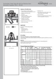
A. Pivot Pins <strong>and</strong> Bushings<br />
Maximum strength is achieved by utilizing<br />
large diameter pins constructed of high<br />
tensile materials. These materials provide<br />
superior wear <strong>and</strong> gall resistance as a result<br />
of their high Brinnell Hardness (BHN)<br />
together with a selected difference in<br />
hardness between mating parts.<br />
B. Grease Fittings<br />
Although lubrication is not essential to the<br />
operation of the Tilted Disc Check <strong>Val</strong>ve,<br />
grease fittings are used to assure even<br />
longer life <strong>and</strong> greater dependability.<br />
C. Disc Position Indicator<br />
A unique connection provides an accurate<br />
indication of the disc position at all times.<br />
St<strong>and</strong>ard on sizes 6” <strong>and</strong> larger.<br />
D. Disc <strong>and</strong> Seat Rings<br />
Superior wear <strong>and</strong> gall resistance are<br />
achieved through the use of materials<br />
having a high Brinnell Hardness (BHN)<br />
together with a selected difference in<br />
hardness between the disc <strong>and</strong> seat rings.<br />
Leak tight seating is attained at all working<br />
pressures by utilizing a 20º seating<br />
angle which provides excellent sealing<br />
characteristics. This angle, by its nature, is<br />
self releasing <strong>and</strong> therefore prevents any<br />
binding of the disc <strong>and</strong> seat.<br />
E. Disc<br />
A hydrodynamically balanced design<br />
provides minimum resistance to flow, lift<br />
<strong>and</strong> stabilization, <strong>and</strong> excellent flow<br />
characteristics.<br />
F. Body<br />
Ultra low head loss is the result of<br />
streamlined body contouring <strong>and</strong> a<br />
flow area through the seat which is a<br />
minimum of 40% greater than nominal<br />
pipe size.<br />
G. Stop Lugs<br />
Positive stops are accurately positioned<br />
to prevent disc flutter at both high <strong>and</strong><br />
low flow velocities, while maintaining ultra<br />
low head loss characteristics.<br />
H. Inspection Ports<br />
Ports allow access to the upstream <strong>and</strong><br />
downstream sides of the seat, <strong>and</strong> also<br />
serve as mounting ports for optional<br />
dashpots.<br />
2<br />
Copyright © 2005 <strong>Val</strong>-<strong>Matic</strong> <strong>Val</strong>ve & Mfg. <strong>Corp</strong>.
T<br />
he Tilted Disc Check <strong>Val</strong>ve is the premier check<br />
valve in the <strong>Val</strong>-<strong>Matic</strong> family. It offers unrivaled<br />
versatility <strong>and</strong> reliability while providing<br />
a significant cost savings over the life of<br />
the valve. While some valves are ideally suited to a specific<br />
application or orientation, the Tilted Disc is appropriate in<br />
any number of installation configurations.<br />
In a single pump system, or a system where only one pump<br />
is operating at a time, Tilted Disc Check <strong>Val</strong>ves are commonly<br />
used with both centrifugal <strong>and</strong> turbine pumps where<br />
flow rates are in the range of 4-20 ft/sec <strong>and</strong> pressures<br />
are up to 400 PSI.<br />
Multiple pump systems, systems set up to reduce slamming,<br />
<strong>and</strong> systems set up to provide high capacity are ideal applications<br />
for the Tilted Disc. Depending on the system pressure,<br />
multiple pumps or parallel pumps can cause a rapid<br />
flow reversal upon system shut-down <strong>and</strong> the flow rate can<br />
vary constantly. The Tilted Disc is offered with optional top<br />
or bottom mounted oil dashpots to aid in disc closure in multiple<br />
pump systems even after a power failure.<br />
In closed tank surge applications, such as a hydropneumatic<br />
tank, it is critical to have a check valve close rapidly to prevent<br />
reverse flow through the pump after pump stoppage.<br />
The Tilted Disc Check <strong>Val</strong>ve with bottom mounted dashpot<br />
is the preferred solution in this application, as it allows for<br />
space constraints, <strong>and</strong> because of the dashpot, allows the<br />
valve to close rapidly <strong>and</strong> still prevent slamming.<br />
<strong>Val</strong>-<strong>Matic</strong> Tilted Disc Check <strong>Val</strong>ves are used worldwide to<br />
offer superior service <strong>and</strong> features in any number of applications<br />
<strong>and</strong> environments. Further information on specific<br />
application parameters <strong>and</strong> the benefits of the Tilted Disc<br />
Check <strong>Val</strong>ve are available online at www.valmatic.com<br />
including the White Paper AEG-301.<br />
Applications<br />
3
Energy Efficient<br />
PLUS...<br />
The <strong>Val</strong>-<strong>Matic</strong> Tilted Disc Check <strong>Val</strong>ve<br />
...Non-Slam Closure<br />
...Wear Resistance<br />
...Leak Tight Seating<br />
...Versatility of Operation<br />
provides energy efficient operation while easily h<strong>and</strong>ling the most<br />
severe <strong>and</strong> dem<strong>and</strong>ing applications with features such as non-slam<br />
closure, wear resistance, leak tight seating, <strong>and</strong> versatility of operation.<br />
This high performance check valve performs well in any number of<br />
operating conditions <strong>and</strong> has the added benefit of extremely low<br />
headloss characteristics.<br />
ENERGY EFFICIENT:<br />
The Tilted Disc conserves energy <strong>and</strong> provides the lowest operating<br />
cost because it provides some of the lowest pressure loss characteristics<br />
of any check valve available today. This ultra low head loss is<br />
the result of a streamlined body contouring <strong>and</strong> a hydrodynamically<br />
designed disc, in combination with a flow area through the seat that<br />
is 40% greater than nominal pipe size. (Figure 1)<br />
The energy savings realized by using a 30” Tilted Disc Check <strong>Val</strong>ve<br />
instead of a traditional swing check valve would pay for the valve<br />
in approximately six years. From that point forward the owner will<br />
continue to realize a savings in energy costs of over $3,600 a year.<br />
(see page 10 for details)<br />
Figure 1<br />
Streamline flow combined with full flow<br />
area provides low head loss<br />
Tilted Disc Check <strong>Val</strong>ve<br />
Short disc<br />
stroke reduces<br />
water hammer<br />
NON-SLAM CLOSING:<br />
The non-slam closing characteristics of the Tilted Disc are achieved by<br />
utilizing a short disc stroke, unique disc counteraction, <strong>and</strong> fixed pivot<br />
pins without stem packing. The short disc stroke, resulting from the angled<br />
seat design, is only 40º as compared to the approximate 80º to<br />
90º stroke found in a conventional swing check valve. This short stroke<br />
reduces the closing time of the valve disc. The reduced closing time<br />
minimizes flow reversal <strong>and</strong> the water hammer effect normally associated<br />
with the sudden stopping of a reverse flow. (Figure 2)<br />
The disc counteraction is the result of an offset pivot which divides the<br />
disc into approximately a one third/two thirds proportion. This allows<br />
the two thirds of flow that passes below the pivot to be counteracted<br />
by the one third that passes above the pivot. This counteraction reduces<br />
slamming by providing a self-cushioning effect not found in conventional<br />
swing-check valves. (Figure 3)<br />
Finally, while conventional swing check valves have rotating stems with<br />
packing, the Tilted Disc Check <strong>Val</strong>ve’s disc rotates freely on fixed pins<br />
providing low inertia <strong>and</strong> friction to accelerate disc closure.<br />
Figure 2<br />
Figure 3<br />
Conventional Swing Check <strong>Val</strong>ve<br />
Long disc stroke increases potential for water hammer<br />
Disc counteraction has<br />
self-cushioning effect<br />
4
High Performance<br />
Positive disc stop<br />
WEAR RESISTANCE:<br />
Extended valve life is the result of excellent wear resistance brought about by such<br />
design features as disc stabilization <strong>and</strong> lift <strong>and</strong> tilt disc action along with a meticulous<br />
selection of materials of construction for those components in working contact.<br />
Our hydrodynamic design provides lift <strong>and</strong> disc stabilization during flow. Tests conducted<br />
by an independent laboratory showed the disc to be extremely stable during both low<br />
<strong>and</strong> high flow conditions thereby minimizing wear associated with disc flutter. (Figure 4)<br />
The disc pivot is eccentrically located in a manner that allows the disc to lift <strong>and</strong> tilt into<br />
<strong>and</strong> out of the body seat without sliding or binding. This unique tilting action reduces the<br />
disc to seat contact <strong>and</strong> its resulting wear. (Figure 5)<br />
High wear resistant materials are provided as st<strong>and</strong>ard for all contact parts such as<br />
pivot <strong>and</strong> seating surfaces.<br />
LEAK TIGHT SEATING:<br />
Leak tight is achieved by utilizing a 20º seating angle <strong>and</strong> maintaining a slight pivot clearance.<br />
The 20º seating angle offers optimum taper-sealing qualities while also having nonbinding,<br />
self-releasing characteristics. The small amount of pivot clearance allows the disc<br />
to close <strong>and</strong> seal on the body seat without pivot interference. (Figure 6)<br />
To demonstrate the excellent seating <strong>and</strong> wear resistant qualities of the Tilted Disc Check<br />
<strong>Val</strong>ve, an extensive cycle test was conducted <strong>and</strong> witnessed by an independent engineering<br />
consulting firm. Results of that test show that even after more than 100,000 cycles, the<br />
<strong>Val</strong>-<strong>Matic</strong> Tilted Disc Check <strong>Val</strong>ve had less than 10% of the allowable leakage for NEW<br />
valves as called for in the testing sections of AWWA <strong>and</strong> MSS specifications for valves.<br />
Copies of the test results are available upon request.<br />
Figure 4<br />
Lift <strong>and</strong> tilt<br />
action prevents<br />
wear<br />
Figure 5<br />
Hydrofoil design<br />
provides disc<br />
stabilization<br />
Disc moves away from<br />
seal as it rotates<br />
Optional Equipment<br />
In addition to the many improved features <strong>and</strong> operating characteristics found in the basic Tilted<br />
Disc that separate it from conventional swing-check valves, the <strong>Val</strong>-<strong>Matic</strong> Tilted Disc Check <strong>Val</strong>ve<br />
offers unrivaled versatility of operation with the following optional equipment.<br />
Small amount<br />
of clearance<br />
around pin<br />
when disc is<br />
seated<br />
Pivot clearance<br />
assures drop<br />
tight seating<br />
Limit Switch<br />
SCADA compatible limit switches can be utilized with the disc position indicator for remote panel<br />
read outs <strong>and</strong>/or secondary system operations. Switches can be provided to indicate the fully<br />
open, fully closed, or combination of both valve positions. (Figure 7)<br />
Figure 6<br />
Combination indicator <strong>and</strong> contact striker<br />
Disc By-Pass<br />
By-Pass bosses are provided upstream <strong>and</strong> downstream of the valve disc. When specified,<br />
these bosses are drilled <strong>and</strong> fitted with the necessary piping <strong>and</strong> shut-off valves to create a<br />
manual or automatic disc by-pass.<br />
<strong>Val</strong>ve Size 2-4” 6” 8” 10” 12” 14” 16” 18”<br />
By-Pass Size N/A 1.5” 1.5” 2” 2” 2” 3” 3”<br />
<strong>Val</strong>ve Size 20” 24” 30” 36” 42” 48” 54” 60”<br />
By-Pass Size 3” 3” 4” 6” 6” 6” 8” 8”<br />
Metric dimensions are available on www.valmatic.com.<br />
Limit<br />
switch<br />
Figure 7<br />
5
Optional Dashpots<br />
BOTTOM MOUNTED OIL DASHPOT<br />
Bottom Mounted Oil Dashpots (BMOD) further reduce the water<br />
hammer potential associated with systems having rapid flow<br />
reversal characteristics. These critical conditions are normally<br />
found in piping systems which have high shut-off heads, <strong>and</strong>/or<br />
use pressure tanks or surge tanks. BMOD’s are not directly connected<br />
to the disc, <strong>and</strong> therefore allow the valve disc to open<br />
freely without restriction <strong>and</strong> close freely for 90% of its travel,<br />
for the remainder of it’s travel, the disc will contact the dashpot<br />
snubber rod. Once contact is made, the speed of closure for<br />
the final 10% of disc movement can be adjusted to a rate best<br />
suited for the application.<br />
The BMOD is a self-contained oil operated system which has an<br />
air gap between the system media <strong>and</strong> the dashpot cylinder.<br />
This air gap positively prevents any pressurized hydraulic fluid<br />
from entering the valve housing <strong>and</strong> contaminating the system<br />
media. The BMOD is installed in the bottom inspection port of<br />
the Tilted Disc <strong>and</strong> is available on valve sizes 6” <strong>and</strong> larger.<br />
When necessary, the unit can also be field installed.<br />
Tilted Disc Check <strong>Val</strong>ve with Bottom Mounted Oil Dashpot<br />
Disc contacts dashpot snubber<br />
rod for final 10% of stroke<br />
Rod wiper with scrapers<br />
Snubber rod<br />
Air gap<br />
Adjustable speed control<br />
Oil accumulator<br />
Figure 1<br />
Sequence of Operation<br />
The last 10% of closing of the check valve can be controlled by an optional hydraulic dashpot cylinder to prevent slamming where<br />
rapid flow reversals are expected. (Figure 1) The cylinder rod pushes against a snubber rod which in turn makes contact with the<br />
valve disc. Both sides of the hydraulic cylinder are connected to a pressurized oil accumulator which is held at the maximum line<br />
pressure plus 50 psi. Because the cylinder piston has a greater pressure area opposite the rod end, the air pressure in the accumulator<br />
will tend to extend the rod. The opening spring is also designed to extend the rod in case air pressure is lost.<br />
OPENING STROKE:<br />
When the water system pump is started, the water pressure will force the check valve disc open. The air pressure in the accumulator<br />
<strong>and</strong> the spring will extend the cylinder <strong>and</strong> snubber rods into the valve port.<br />
6<br />
CLOSING STROKE:<br />
When the water system pump is stopped, the weight of the disc <strong>and</strong> reverse flow of water will force the check valve disc<br />
closed thereby striking the snubber rod. The snubber rod will push on the cylinder rod in the direction shown <strong>and</strong> force oil<br />
through the adjustable flow control valve. The flow control valve will control the speed of closure for the last 10% of valve<br />
travel in typically 1 to 5 seconds.
Optional Dashpots, CONT.<br />
TOP MOUNTED OIL DASHPOT<br />
The Top Mounted Oil Dashpot (TMOD) is directly connected to the<br />
disc <strong>and</strong> provides full control of the valve disc to further reduce the<br />
potential for surges <strong>and</strong> water hammer.<br />
The unit provides single stage adjustable speed control of the disc’s<br />
travel to the open position thereby reducing system pressure surges<br />
upon pump start-up. Two stage control is provided during valve closure,<br />
reducing the water hammer <strong>and</strong> surges associated with rapid<br />
flow reversal systems. The first stage controls 90% of the disc closure,<br />
while the second stage controls the final, critical 10% of closure.<br />
All controls are independent of each other <strong>and</strong> can be field adjusted<br />
to best suit the application. For example, the first stage of closing<br />
can be at a slower rate than the opening rate, with the final 10%<br />
of closure at even a slower rate. Tilted Disc Check <strong>Val</strong>ves with dashpots<br />
are not intended to replace system surge control equipment, but<br />
to further minimize the slamming <strong>and</strong> water hammer associated with<br />
conventional swing check valves. The TMOD is also a self-contained<br />
oil operated system which has an air gap spacer between the system<br />
media <strong>and</strong> the dashpot. The air gap prevents any possibility of the<br />
hydraulic fluid from entering the system <strong>and</strong> contaminating the line<br />
media. TMOD are available for all valve sizes 6” <strong>and</strong> larger. A Quick<br />
Change Coupling is provided to facilitate removal of the cylinder<br />
should it be necessary without removal of the valve from the line.<br />
Adjustable<br />
second stage<br />
speed control<br />
Air gap<br />
Direct disc<br />
connection<br />
provides full<br />
disc control<br />
Tilted Disc Check <strong>Val</strong>ve with Top<br />
Mounted Oil Dashpot<br />
Oil Accumulator<br />
See pages 8-9 for application.<br />
Rod wiper with<br />
scrapers<br />
Adjustable first<br />
stage speed<br />
controls<br />
Hydraulic<br />
Cylinder<br />
Dashpot<br />
Spacer<br />
Coupling<br />
Retainer<br />
Retainer<br />
Screw<br />
Coupling<br />
Half<br />
Quick Change Coupling<br />
Coupling<br />
Half<br />
Sequence of Operation<br />
Connecting<br />
Rod<br />
OPENING STROKE:<br />
When the water system pump is started, the water column will<br />
force the check valve disc open thereby pushing the cylinder rod<br />
upward. (Figure 2) The oil over the cylinder piston will become<br />
pressurized <strong>and</strong> flow through the open flow control valve <strong>and</strong><br />
into the pressurized oil accumulator typically in 5-30 sec. Oil<br />
will also be drawn into the lower portion of the cylinder through<br />
the check valve portion of the close flow control valve <strong>and</strong> the<br />
vented oil accumulator.<br />
CLOSING STROKE:<br />
When the water system pump is stopped, the weight of the<br />
disc <strong>and</strong> reverse flow of the water will force the check valve<br />
disc closed thereby pulling the cylinder rod down. The oil<br />
under the cylinder piston will become pressurized <strong>and</strong> flow<br />
through the close flow control valve <strong>and</strong> into the vented oil accumulator<br />
typically in 5-30 sec. Oil will also flow into the top<br />
of the cylinder from the pressurized oil accumulator through<br />
the check portion of the open flow control valve. The pressurized<br />
oil accumulator is maintained at 20% of the water line<br />
pressure to assist in valve closure.<br />
FINAL 10% OF CLOSURE:<br />
During the last 10% of closure, the larger diameter portion of<br />
the cylinder rod enters a cushion chamber in the lower head of<br />
the dashpot cylinder. The speed of closure during the last 10% of<br />
closure can be controlled further using the cushion control adjustment<br />
screw located on the cylinder head, typically 1 to 5 seconds.<br />
Figure 2<br />
7
<strong>Val</strong>ve Selection<br />
The Tilted Disc Check <strong>Val</strong>ve is<br />
available in three configurations:<br />
- Basic<br />
- Bottom Mounted Oil Dashpot<br />
- Top Mounted Oil Dashpot<br />
It is important to note that the dashpot configurations include<br />
high pressure oil cylinders <strong>and</strong> full rated disc connections.<br />
With oil dashpots, the disc is rigidly controlled as<br />
opposed to an air cushion which only produces a minimal<br />
dampening effect.<br />
To select the proper valve configuration, several criteria<br />
must be considered. The number of pumps <strong>and</strong> the static<br />
head will effect how rapidly the water column will reverse<br />
when a pump is stopped. The type of pump control will<br />
effect the required closing characteristics of the valve.<br />
Typical types of control include on-off, soft-start, variable<br />
speed, <strong>and</strong> electrically operated control valves. The<br />
length of the piping system is used to estimate surges<br />
from changes in flow velocity. The type of surge relief<br />
system dictates the required closing time for the valve.<br />
Surge tanks require a quick-closing valve to prevent the<br />
loss of stored water back through the pump. The criteria<br />
listed above are used to select the best valve configuration<br />
as follows.<br />
1. Basic <strong>Val</strong>ve<br />
The basic valve features a short stroke angle of 40°<br />
which provides rapid disc closure in less than ½ second.<br />
This feature will provide non-slam closure in low service<br />
pumping applications. Basic valves are typically used<br />
when the static head is less than 100 feet in single or multiple<br />
pump application. A common application is the filter<br />
backwash pumps in a water treatment plant.<br />
3. Top Mounted Oil Dashpot<br />
The top mounted oil dashpot controls both the full opening<br />
<strong>and</strong> full closing stroke of the valve. Also, the last 10%<br />
of travel of valve closure is independently controlled by<br />
an adjustable hydraulic cylinder cushion. With the top<br />
mounted oil dashpot, the disc is mechanically linked to a<br />
hydraulic cylinder <strong>and</strong> linkage is designed to withst<strong>and</strong><br />
the full thrust of the disc when subjected to line pressure.<br />
<strong>Val</strong>ves equipped with top mounted oil dashpots have<br />
been used in extreme service applications up to the full<br />
flow <strong>and</strong> pressure rating of the valve. When there is insufficient<br />
space to provide a straight run of pipe between<br />
the pump <strong>and</strong> the valve, the top mounted dashpot will<br />
control the disc movement <strong>and</strong> prolong the life of the<br />
valve.<br />
The opening <strong>and</strong> closing strokes are field adjustable in<br />
the 5-30 second range. A greater closure time may produce<br />
excessive reverse flow through the pump. The final<br />
10% of closure is adjustable in the 1-5 second range to<br />
prevent slam.<br />
By setting the valve opening time to 20 seconds, the system<br />
flow rate will rise to 50% in about 2 seconds which<br />
equates to the critical time period of a system 3,000 ft.<br />
in length. On longer systems, the dashpot will not have an<br />
appreciable effect on pressure surges; therefore, a surge<br />
analysis <strong>and</strong> surge equipment are recommended.<br />
On very long systems, a power operated control valve<br />
is sometimes used. The control valve is electrically wired<br />
to the pump control <strong>and</strong> is programmed to slowly open<br />
<strong>and</strong> close to gradually change the flow rate in the system<br />
over a 30-300 second period. However, after a power<br />
outage, the control valve may not be capable of closing<br />
rapidly enough to prevent back spinning of the pump or<br />
loss of water from a surge tank. In these cases, a Tilted<br />
Disc ® is often installed upstream of the control valve.<br />
2. Bottom Mounted Oil Dashpot<br />
Dashpots are used on high service pumping applications<br />
where there is a propensity for rapid flow reversal. The<br />
dashpot consists of a hydraulic cylinder <strong>and</strong> snubber rod<br />
which contacts the disc during closing. The dashpot controls<br />
the last 10% of valve closure to reduce water hammer<br />
<strong>and</strong> prevent slamming of the disc.<br />
The valve is effective on shorter length systems with static<br />
heads up to the valve rating. The dashpot is also used on<br />
longer systems where rapid flow reversal occurs due to<br />
the use of surge tanks or in multiple pump systems. The<br />
dashpot is field adjustable <strong>and</strong> typically set to control the<br />
last 10% of closure in 1-5 seconds. A greater closure time<br />
may produce excessive reverse flow through the pump.<br />
8
Application Graph<br />
The application graph illustrates the range of use for three valve configurations: 1) basic valve, 2) bottom mounted oil<br />
dashpot, <strong>and</strong> 3) top mounted oil dashpot. For example, on a 2,500 ft. long water transmission main operating at 150 ft. of<br />
head, a Tilted Disc Check <strong>Val</strong>ve with a top mounted oil dashpot would be selected. Or, if a surge relief system is provided,<br />
then the bottom mounted oil dashpot configuration may be used.<br />
RECOMMENDATION FOR APPLICATION OF VAL-MATIC TILTED DISC ® CHECK VALVES<br />
Type of Installation Length Static Head Surge Relief System Recommended Check <strong>Val</strong>ve<br />
Single Pump 0-1000 ft. 0-100 ft. NONE Basic <strong>Val</strong>ve<br />
Multiple Pump 0-1000 ft. 0-100 ft. NONE Basic <strong>Val</strong>ve<br />
Single/Multiple Pump 0-1000 ft. > 100 ft. NONE <strong>Val</strong>ve w/BMOD<br />
Single/Multiple Pump 1000-3000 ft. 0-200 ft. NONE <strong>Val</strong>ve w/ TMOD<br />
Single/Multiple Pump 1000-3000 ft. 0-200 ft. Relief <strong>Val</strong>ve/Surge Tank <strong>Val</strong>ve w/ BMOD<br />
Single/Multiple Pump 1000-3000 ft. > 200 ft. Relief <strong>Val</strong>ve <strong>Val</strong>ve w/ TMOD<br />
Single Pump > 3000 ft. > 50 ft. Relief <strong>Val</strong>ve <strong>Val</strong>ve w/ TMOD<br />
Single Pump > 3000 ft. > 50 ft. Surge Tank/Control <strong>Val</strong>ve <strong>Val</strong>ve w/ BMOD<br />
Metric dimensions are available on www.valmatic.com.<br />
9
Head Loss Chart<br />
(CUBIC METERS PER HOUR)<br />
HEADLOSS IN FEET OF WATER<br />
Energy Cost Savings<br />
The Tilted Disc possesses the lowest head loss of any check valve available today, allowing the least amount<br />
of energy during system operation to be consumed. The continuous electrical energy savings that result from<br />
using the <strong>Val</strong>-<strong>Matic</strong> Tilted Disc rather than a conventional swing check valve can be calculated by using the<br />
following formula:<br />
ELECTRICAL COST SAVINGS<br />
PER YEAR (ECS/Y)<br />
FLOW OF WATER IN GALLONS PER MINUTE<br />
=<br />
GPM x HLD x Sg x C/Kwh x 1.65<br />
PE x ME<br />
(METERS OF WATER)<br />
FLOW<br />
COEFFICIENTS<br />
SIZE Cv K<br />
2” 102 1.37<br />
3” 248 1.17<br />
4” 475 1.01<br />
6” 1,160 0.86<br />
8” 2,200 0.75<br />
10” 3,600 0.69<br />
12” 5,400 0.63<br />
14” 7,600 0.59<br />
16” 10,030 0.58<br />
18” 13,200 0.54<br />
20” 16,800 0.50<br />
24” 25,500 0.45<br />
30” 42,000 0.41<br />
36” 63,000 0.38<br />
42” 90,000 0.34<br />
48” 119,000 0.33<br />
54” 155,000 0.31<br />
60” 195,000 0.30<br />
Cv = The number of<br />
U.S. gallons/minute of<br />
60°F water that will flow<br />
through the valve with a<br />
1 PSI pressure drop across<br />
the valve.<br />
K = resistance coefficient<br />
(dimensionless.)<br />
WHERE:<br />
GPM<br />
- Pump capacity in gallons per minute<br />
Sg - Specific gravity (Water = 1)<br />
PE<br />
ME<br />
C/Kwh<br />
- Pump efficiency<br />
- Motor efficiency<br />
- Cost per kilowatt hour<br />
HLD - Head loss difference between<br />
<strong>Val</strong>-<strong>Matic</strong> Tilted Disc <strong>and</strong> conventional<br />
swing check valve in feet of water.<br />
EXAMPLE:<br />
Size 30”<br />
Electrical Cost Savings Per Year:<br />
SAVINGS OVER 40YR. VALVE LIFE:<br />
10<br />
GPM = 20,000 † <strong>Val</strong>ues used are<br />
Sg = 1<br />
considered average<br />
<strong>and</strong> for demonstration<br />
C/Kwh = .1† only. Contact your local<br />
power utility, pump <strong>and</strong><br />
PE = .85† motor manufacturer to<br />
ME = .85† establish your actual<br />
values.<br />
HLD = .8<br />
ESC/Y = 20,000 x .8 x 1 x .1 x 1.65<br />
.85 x .85<br />
$3,654.00<br />
$146,160.00<br />
Note:<br />
The savings are based on a system operating 24 hours per day for 365 days. For systems operating less, multiply the savings by the<br />
percentage of usage. EXAMPLE: 18 hours = 75% Multiply 75 x ECS/Y = $2,740
Sample Specification<br />
Scope<br />
1.1 This specification covers the design, manufacture, <strong>and</strong> testing of 3 in (80 mm) through 60 in (1500 mm) Tilted Disc Check <strong>Val</strong>ves suitable for<br />
pressures up to 400 psig (2750 kPa) water service.<br />
1.2 The Check <strong>Val</strong>ves shall be of the Tilted Disc, metal seated, full body type capable of accepting optional bottom or top mounted oil dashpots.<br />
St<strong>and</strong>ards, Approvals <strong>and</strong> Verification<br />
2.1 The valves shall be certified to NSF/ANSI 61 Drinking Water System Components - Health Effects <strong>and</strong> certified to be Lead-Free in<br />
accordance with NSF/ANSI 61, Annex G.<br />
2.2 A 20 in. valve or larger shall be proof of design cycle tested through 250,000 cycles in the horizontal position <strong>and</strong> leak tested at the rated<br />
pressure. The leakage rate shall be less then 1 fluid ounce per hour per inch of valve size after the test.<br />
2.3 Manufacturer shall have a quality management system that is certified to ISO 9001 by an accredited, certifiying body.<br />
Connections<br />
3.1 The valves shall be provided with drilled flanges in accordance with ANSI B16.1 for Class 125 or Class 250 iron flanges <strong>and</strong> ANSI B16.42<br />
for Class 150 ductile iron flanges. Iron flanges shall be flat faced.<br />
3.2 Flanged inspection ports shall be provided upstream <strong>and</strong> downstream of the valve disc for inspection or use with optional dashpots on 6 in<br />
(150 mm) <strong>and</strong> larger valves.<br />
Design<br />
4.1 The valve body shall consist of two sections bolted together as a central diagonal flange inclined at an angle of 55 degrees. The inlet body<br />
section shall contain a seat ring positioned <strong>and</strong> captured by the diagonal flange. The outlet body section shall accept eccentrically located pivot<br />
pin trunnions with sealed covers <strong>and</strong> lubrication grease fittings.<br />
4.2 The eccentric pivot trunnions shall be located to divide the disc into approximately 1/3 <strong>and</strong> 2/3 proportions <strong>and</strong> also allow the seating<br />
surface of the disc to rotate away from the seating surface of the seat ring without contact. Clearance shall be provided between the pivot pin<br />
<strong>and</strong> bushing when the disc is seated to prevent binding <strong>and</strong> to ensure a tight seal.<br />
4.3 The flow area through the valve body inlet <strong>and</strong> outlet shall be equal to the nominal pipe size <strong>and</strong> gradually increase to an area 40 percent<br />
greater at the valve seat.<br />
4.4 A position indicator shall be supplied on 6 in. <strong>and</strong> larger valves <strong>and</strong> visually show disc position at all times.<br />
4.5 The valve disc <strong>and</strong> seat shall have a seating surface finish of 32 micro-inch or better to ensure positive seating at all pressures. The leakage<br />
rate shall not exceed one-half of the allowable rate allowed by AWWA St<strong>and</strong>ard C508 or 0.5 oz (15 ml) per hour per inch (mm) of valve size.<br />
4.6 6 in. <strong>and</strong> larger valves shall be capable of accepting a field installed Bottom Mounted Oil Dashpot.<br />
4.7 The valve flow way shall be contoured <strong>and</strong> unrestricted to provide full flow areas at all locations within the valve. Full flow shall be based<br />
on an open stroke of 40 degrees to assure stabilization of the disc when open. Cv flow coefficients shall ve verified by an independent testing<br />
laboratory.<br />
Materials<br />
5.1 The valve body shall be constructed of ASTM A126 Class B cast iron for Class 125 <strong>and</strong> Class 250 valves up to 10 in (250 mm). 12 in<br />
(300mm) <strong>and</strong> larger Class 250 <strong>and</strong> Class 150 valves shall be constructed of ductile iron ASTM A536 Grade 65-45-12.<br />
5.2 The disc in sizes up to 10 in (250mm) shall be one-piece construction with integral seat <strong>and</strong> constructed of ASTM B271 Alloy C95400<br />
aluminum bronze. 12 in (300mm) <strong>and</strong> larger discs shall be ASTM A126 Class B cast iron. Discs furnished for 12 in (300mm) <strong>and</strong> larger valves<br />
with top oil dashpots shall be constructed of ASTM A536 Grade 65-45-12 ductile iron. The disc seating ring shall be ASTM B271 Alloy C95500<br />
centrifugally cast aluminum bronze. The mating seat ring located in the body shall be ASTM B271 Alloy C95400 centrifugally cast aluminum<br />
bronze.<br />
5.3 The pivot pins shall be ASTM B505 Alloy C95500 aluminum bronze <strong>and</strong> shall be guided by a bushing constructed of ASTM B505 Alloy<br />
C95400 aluminum bronze (12 in. <strong>and</strong> larger valves).<br />
Options<br />
6.1 Single or double By-Pass piping shall be provided when specified.<br />
6.2 A Nema-4 machine tool type limit switch with DPDT contacts shall be provided when specified. The switch shall be mounted to the inspection<br />
cover <strong>and</strong> have an adjustable trip arm for sensing the closed position.<br />
6.3 A (bottom mounted) (top mounted) oil dashpot shall be provided when specified.<br />
6.4 The valve interiors <strong>and</strong> exteriors shall be coated with an NSF/ANSI 61 certified fushion bonded epoxy in accordance with AWWA C550<br />
when specified.<br />
Manufacture<br />
7.1 The valves shall be hydrostatically tested at 1.5 times their rated cold working pressure. Additional tests shall be conducted per AWWA,<br />
ANSI, MSS or API st<strong>and</strong>ards when specified. When requested, the manufacturer shall provide test certificates, dimensional drawings, parts list<br />
drawings, <strong>and</strong> operation <strong>and</strong> maintenance manuals.<br />
7.2 The exterior of the valve shall be coated with a universal alkyd primer. The valve interior shall be coated with an epoxy coating approved<br />
for potable water.<br />
7.3 The Tilted Disc ® Check <strong>Val</strong>ves shall be Series #9000, 9000B (with bottom oil dashpot), or 9000T (with top oil dashpot) as manufactured by<br />
<strong>Val</strong>-<strong>Matic</strong> ® <strong>Val</strong>ve & Mfg. <strong>Corp</strong>oration, Elmhurst, IL. USA or approved equal.<br />
* See www.valmatic.com for full spec.<br />
11
Pressure / Temperature Ratings<br />
The <strong>Val</strong>-<strong>Matic</strong> Tilted Disc is offered in three different flange classes: 125, 250, <strong>and</strong> 150. This chart indicates the<br />
maximum non-shock pressures for each flange class.<br />
NOTE: The Ductile Iron 9600 series, Class 150 is rated for 285 PSI <strong>and</strong> can be bolted directly to flanges with 150<br />
or 125 ANSI class drilling.<br />
TEMP.<br />
ºF<br />
MAXIMUM NON-SHOCK PRESSURE - PSI<br />
SERIES 9800 SERIES 9700 SERIES 9600<br />
CLASS 125 CLASS 250 CLASS 150<br />
CAST IRON DUCTILE IRON DUCTILE IRON<br />
2” - 12” 14” - 24” 30” - 60” 2” - 12” 14” - 24” 30” - 60” 2” - 60”<br />
50 - 300mm 350 - 600mm 800 - 1500mm 50 - 300mm 350 - 600mm 800 - 1500mm 50 - 1500mm<br />
100º<br />
285<br />
200 150 150 400 300 300<br />
150º 270<br />
200º 190 135 115 370 280 250 260<br />
250º * * * 355 270 225 250<br />
HYDROSTATIC<br />
TEST PRESSURE<br />
300 230 230 600 450 450 450<br />
* For service above 200º F use series 9700 or 9600.<br />
Quality Assurance<br />
<strong>Val</strong>-<strong>Matic</strong>’s quality assurance is the<br />
sum of imaginative design, solid<br />
engineering, precise manufacturing<br />
<strong>and</strong> dedicated people.<br />
These all combine to ensure total<br />
customer satisfaction. We recognize<br />
the need for, <strong>and</strong> encourage, individual<br />
pride <strong>and</strong> the self-satisfaction<br />
which is gained in producing<br />
reliable, quality valves.<br />
This quality attitude permeates<br />
through the corporation from the<br />
president to our newest employee.<br />
Testing is the backbone of our<br />
quality assurance. Every Tilted<br />
Disc Check <strong>Val</strong>ve is 100% tested<br />
including hydrostatic testing to<br />
assure the integrity of the casting<br />
<strong>and</strong> seating compositing.<br />
12
Installation Dimensions <strong>and</strong> Construction<br />
Tilted Disc Check <strong>Val</strong>ve<br />
F<br />
All dimensions presented in inches. Metric dimensions are available on www.valmatic.com.<br />
C<br />
G<br />
B<br />
J<br />
Inspection ports are st<strong>and</strong>ard on sizes 6” <strong>and</strong> larger.<br />
D<br />
A<br />
Size<br />
2<br />
3<br />
4<br />
6<br />
8<br />
10<br />
12<br />
14<br />
16<br />
ANSI<br />
Class<br />
Model<br />
No.<br />
125 9802<br />
A B C D F G J<br />
4.75 6 .75<br />
Wt.<br />
Lbs.<br />
50<br />
Size<br />
ANSI<br />
Class<br />
Model<br />
No.<br />
125 9818<br />
A B C D F G J<br />
22.75 25 1.56<br />
250 9702 9.5 5 6.5 .88 11 4.25 3.75 60 18 250 9718 33 24.75 28 2.38 36 15 15 1,770<br />
150 9602 4.75 6 .75 55 150 9618 22.75 25 1.56 1,509<br />
125 9803<br />
6 7.5 .94<br />
65<br />
125 9820<br />
25 27.5 1.69<br />
250 9703 9.5 6.63 8.25 1.13 12 4.75 4.25 75 20 250 9720 32 27 30.5 2.5 39 16 16 1,970<br />
150 9603 6 7.5 .94 70 150 9620 25 27.5 1.69 1,860<br />
125 9804<br />
7.5 9 .94<br />
80<br />
125 9824<br />
29.5 32 1.88<br />
250 9704 11.5 7.88 10 1.25 13 5.25 4.75 97 24 250 9724 38 32 36 2.75 46 19 18 3,402<br />
150 9604 7.5 9 .94 87 150 9624 29.5 32 1.88 2,925<br />
125 9806<br />
9.5 11 1<br />
156<br />
125 9830<br />
36 38.75 2.13<br />
250 9706 15 10.63 12.5 1.44 16 6.5 6.5 206 30 250 9730 52 39.25 43 3 55 23 22 5,962<br />
150 9606 9.5 11 1 169 150 9630 36 38.75 2.13 5,310<br />
125 9808<br />
11.75 13.5 1.13<br />
295<br />
125 9836<br />
42.75 46 2.38<br />
250 9708 19.5 13 15 1.63 19 8 8 331 36 250 9736 59.5 46 50 3.38 65 27 24 9,003<br />
150 9608 11.75 13.5 1.13 312 150 9636 42.75 46 2.38 8,138<br />
125 9810<br />
14.25 16 1.19<br />
432<br />
125 9842<br />
49.5 53 2.63<br />
250 9710 24.5 15.25 17.5 1.88 23 9.5 8.5 557 42 250 9742 62.5 52.75 57 3.69 73 32 27 12,510<br />
150 9610 14.25 16 1.19 472 150 9642 49.5 53 2.63 11,400<br />
125 9812<br />
17 19 1.25<br />
622<br />
125 9848<br />
56 59.5 2.75<br />
250 9712 24 17.75 20.5 2 26 11 10 790 48 250 9748 65 60.75 65 4 82 37 32 16,770<br />
150 9612 17 19 1.25 673 150 9648 56 59.5 2.75 15,000<br />
125 9814<br />
18.75 21 1.38<br />
890<br />
125 9854<br />
62.75 66.25 3<br />
250 9714 30 20.25 23 2.13 29 12 11.5 1,110 54 250 9754 78 * * * 90.88 39 36 21,600<br />
150 9614 18.75 21 1.38 955 150 9654 62.75 66.25 3 19,000<br />
125 9816<br />
21.25 23.5 1.44<br />
1,160<br />
125 9860<br />
69.25 73 3.13<br />
250 9716 30 22.5 25.5 2.25 32 14 14 1,447 60 250 9760 87 * * * 92 44.25 42 28,258<br />
150 9616 21.25 23.5 1.44 1,256 150 9660 69.25 73 3.13 25,000<br />
Wt.<br />
Lbs.<br />
1,408<br />
1,718<br />
2,698<br />
4,900<br />
7,500<br />
10,500<br />
13,800<br />
17,500<br />
23,000<br />
Flanged ends conform to ANSI specifications B16.1 <strong>and</strong> B16.42. Flanged ends conforming to BS, DIN, <strong>and</strong> ISO specifications are also available.<br />
13
Installation Dimensions <strong>and</strong> Construction<br />
Tilted Disc Check <strong>Val</strong>ve with Bottom Mounted Oil Dashpot<br />
F<br />
A<br />
Integral disc ring <strong>and</strong> bushings<br />
on sizes 10” <strong>and</strong> smaller<br />
G<br />
Disc position indicator<br />
st<strong>and</strong>ard<br />
K<br />
H<br />
J<br />
Dimensions “K” <strong>and</strong> “L” represent the clearance required to remove dashpot unit.<br />
However, dimension “L” can be reduced to 1” for low clearance applications.<br />
Consult factory for dashpot removal instructions.<br />
Metric dimensions are available on www.valmatic.com.<br />
L<br />
Size<br />
6<br />
8<br />
10<br />
12<br />
14<br />
16<br />
18<br />
20<br />
14<br />
ANSI<br />
Class<br />
Model<br />
No.<br />
125 9806B<br />
A F G H J K L<br />
Wt.<br />
Lbs.<br />
174<br />
250 9706B 15 16 6.5 9 16 12 3 224<br />
150 9606B 187<br />
125 9808B<br />
317<br />
250 9708B 19.5 19 8 8 17 11 4 353<br />
150 9608B 334<br />
125 9810B<br />
454<br />
250 9710B 24.5 23 9.5 5 18 9 5 579<br />
150 9610B 494<br />
125 9812B<br />
656<br />
250 9712B 24 26 11 7 20 11 5 824<br />
150 9612B 707<br />
125 9814B<br />
924<br />
250 9714B 30 29 12 4 21 8 5 1,144<br />
150 9614B 989<br />
125 9816B<br />
1,214<br />
250 9716B 30 32 14 5 23 9 5 1,501<br />
150 9616B 1,310<br />
125 9818B<br />
1,462<br />
250 9718B 33 36 15 3 24 7 5 1,824<br />
150 9618B 1,563<br />
125 9820B<br />
1,772<br />
250 9720B 32 39 16 3 25 8 6 2,024<br />
150 9620B 1,914<br />
Size<br />
24<br />
30<br />
36<br />
42<br />
48<br />
54<br />
60<br />
ANSI<br />
Class<br />
Model<br />
No.<br />
125 9824B<br />
A F G H J K L<br />
Wt.<br />
Lbs.<br />
2,752<br />
250 9724B 38 46 19 1* 27 4 6 3,456<br />
150 9624B 2,979<br />
125 9830B<br />
5,024<br />
250 9730B 52 55 23 1* 35 6 8 6,086<br />
150 9630B 5,434<br />
125 9836B<br />
7,624<br />
250 9736B 59.5 65 27 5* 39 2 8 9,127<br />
150 9636B 8,262<br />
125 9842B<br />
10,670<br />
250 9742B 62.5 73 32 5* 43 5 8 12,680<br />
150 9642B 11,570<br />
125 9848B<br />
13,970<br />
250 9748B 65 82 37 2* 52 8 8 16,940<br />
150 9648B 15,170<br />
125 9854B<br />
17,720<br />
250 9754B 78 89 39 7* 55 5 8 21,820<br />
150 9654B 19,220<br />
125 9860B<br />
23,220<br />
250 9760B 87 99 42 7* 64 5 8 28,478<br />
150 9660B 25,220<br />
Flanged ends conform to ANSI specifications B16.1 <strong>and</strong> B16.42. Dimensions are shown<br />
on previous page. Flanged ends conforming to BS, DIN, <strong>and</strong> ISO specifications are<br />
also available.<br />
*Dimension “H” does not extend beyond flange face for valve sizes 24” <strong>and</strong> larger.<br />
Dimension shown is within the flange face. All dimensions presented in inches.
Installation Dimensions <strong>and</strong> Construction<br />
Tilted Disc Check <strong>Val</strong>ve with Top Mounted Oil Dashpot<br />
N<br />
Metric dimensions are available on www.valmatic.com.<br />
H<br />
J<br />
Disc position indicator<br />
st<strong>and</strong>ard<br />
F<br />
A<br />
Integral disc ring <strong>and</strong> bushings<br />
on sizes 10” <strong>and</strong> smaller<br />
<strong>Val</strong>ve<br />
Size<br />
6<br />
8<br />
10<br />
12<br />
14<br />
16<br />
18<br />
20<br />
ANSI<br />
Class<br />
Model<br />
No.<br />
125 9806T<br />
A F H J N<br />
Wt.<br />
Lbs.<br />
196<br />
250 9706T 15 16 23 6.5 12 246<br />
150 9606T 209<br />
125 9808T<br />
381<br />
250 9708T 19.5 19 29 8 17 417<br />
150 9608T 398<br />
125 9810T<br />
518<br />
250 9710T 24.5 23 31 8.5 17 643<br />
150 9610T 558<br />
125 9812T<br />
764<br />
250 9712T 24 26 34 10 21 927<br />
150 9612T 810<br />
125 9814T<br />
1,035<br />
250 9714T 30 29 36 13 21 1,249<br />
150 9614T 1,094<br />
125 9816T<br />
1,420<br />
250 9716T 30 32 43 14 24 1,697<br />
150 9616T 1,506<br />
125 9818T<br />
1,677<br />
250 9718T 33 36 45 15 24 2,206<br />
150 9618T 1,765<br />
125 9820T<br />
2,135<br />
250 9720T 32 39 53 16 28 2,369<br />
150 9620T 2,259<br />
<strong>Val</strong>ve<br />
Size<br />
24<br />
30<br />
36<br />
42<br />
48<br />
54<br />
60<br />
ANSI<br />
Class<br />
Model<br />
No.<br />
125 9824T<br />
A F H J N<br />
Wt.<br />
Lbs.<br />
3,136<br />
250 9724T 38 46 56 18 28 3,814<br />
150 9624T 3,337<br />
125 9830T<br />
5,656<br />
250 9730T 52 55 66 24 36 6,670<br />
150 9630T 6,018<br />
125 9836T<br />
8,338<br />
250 9736T 59.5 65 78 24 36 9,753<br />
150 9636T 8,888<br />
125 9842T<br />
11,670<br />
250 9742T 62.5 73 89 27 43 13,555<br />
150 9642T 12,445<br />
125 9848T<br />
15,040<br />
250 9748T 65 82 99 32 43 17,860<br />
150 9648T 16,090<br />
125 9854T<br />
19,218<br />
250 9754T 78 90.88 122.5 36 48 23,318<br />
150 9654T 20,718<br />
125 9860T<br />
25,514<br />
250 9760T 87 99 120 41.75 60 30,572<br />
150 9660T 27,314<br />
Flanged ends conform to ANSI specifications B16.1 <strong>and</strong> B16.42. Flanged<br />
ends conforming to BS, DIN, <strong>and</strong> ISO specifications are also available.<br />
All dimensions presented in inches.<br />
15
Make the change to QUALITY!<br />
Specify V<br />
Plug <strong>Val</strong>ve with more requested features than any other eccentric<br />
<strong>Val</strong>-<strong>Matic</strong>’s quality of design <strong>and</strong> meticulous workmanship has set<br />
steel screened inlet on Sure Seal ® Foot <strong>Val</strong>ves...a Cam-Centric ® tomer satisfaction is our goal.<br />
the st<strong>and</strong>ards by which all others are measured. Quality design<br />
features such as Type 316 stainless steel trim as st<strong>and</strong>ard on Air<br />
Release, Air/Vacuum <strong>and</strong> Combination Air <strong>Val</strong>ves...combined<br />
resilient/metal to metal seating for Silent Check ® <strong>Val</strong>ves...stabilized<br />
plug valve, <strong>and</strong> the American-BFV ® Butterfly <strong>Val</strong>ve that provides<br />
a field replaceable seat without the need for special tools. These<br />
features coupled with our attention to detail put <strong>Val</strong>-<strong>Matic</strong> valves<br />
in a class by themselves.<br />
components that provide extended life of the Dual Disc ®<br />
Check <strong>Val</strong>ves...high strength <strong>and</strong> wear resistant aluminum bronze<br />
trim as st<strong>and</strong>ard for Tilted Disc ® Check valves...unrestricted full <strong>Val</strong>-<strong>Matic</strong> is totally committed to providing the highest quality<br />
flow area through Swing-Flex ® Check <strong>Val</strong>ves...heavy duty stainless valves <strong>and</strong> outst<strong>and</strong>ing service to our customers. Complete cus-<br />
V<br />
VAL-MATIC VALVE AND MANUFACTURING CORP.<br />
905 RIVERSIDE DRIVE • ELMHURST, IL 60126<br />
630/941-7600 • FAX: 630/941-8042<br />
www.valmatic.com valves@valmatic.com