REVERSE CYCLE HEAT PUMP-CHILLER
REVERSE CYCLE HEAT PUMP-CHILLER
REVERSE CYCLE HEAT PUMP-CHILLER

You also want an ePaper? Increase the reach of your titles
YUMPU automatically turns print PDFs into web optimized ePapers that Google loves.
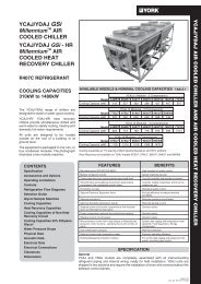
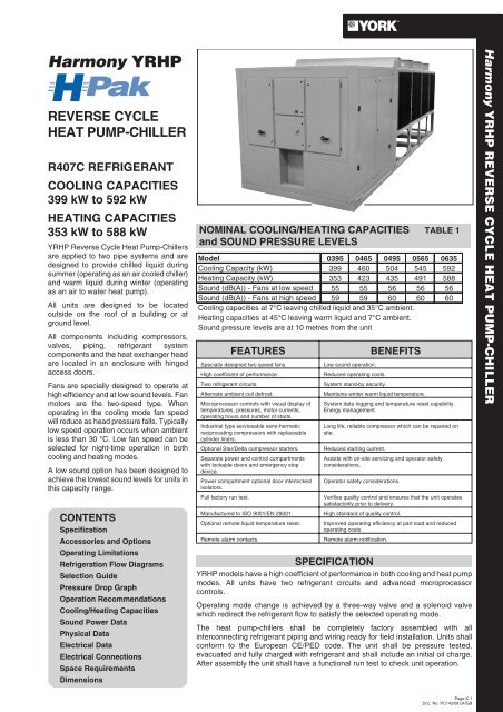
<strong>REVERSE</strong> <strong>CYCLE</strong><br />
<strong>HEAT</strong> <strong>PUMP</strong>-<strong>CHILLER</strong><br />
R407C REFRIGERANT<br />
COOLING CAPACITIES<br />
399 kW to 592 kW<br />
<strong>HEAT</strong>ING CAPACITIES<br />
353 kW to 588 kW<br />
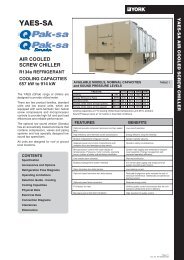
YRHP Reverse Cycle Heat Pump-Chillers<br />
are applied to two pipe systems and are<br />
designed to provide chilled liquid during<br />
summer (operating as an air cooled chiller)<br />
and warm liquid during winter (operating<br />
as an air to water heat pump).<br />
All units are designed to be located<br />
outside on the roof of a building or at<br />
ground level.<br />
All components including compressors,<br />
valves, piping, refrigerant system<br />
components and the heat exchanger head<br />
are located in an enclosure with hinged<br />
access doors.<br />
Fans are specially designed to operate at<br />
high efficiency and at low sound levels. Fan<br />
motors are the two-speed type. When<br />
operating in the cooling mode fan speed<br />
will reduce as head pressure falls. Typically<br />
low speed operation occurs when ambient<br />
is less than 30 °C. Low fan speed can be<br />
selected for night-time operation in both<br />
cooling and heating modes.<br />
A low sound option has been designed to<br />
achieve the lowest sound levels for units in<br />
this capacity range.<br />
CONTENTS<br />
Specification<br />
Accessories and Options<br />
Operating Limitations<br />
Refrigeration Flow Diagrams<br />
Selection Guide<br />
Pressure Drop Graph<br />
Operation Recommendations<br />
Cooling/Heating Capacities<br />
Sound Power Data<br />
Physical Data<br />
Electrical Data<br />
Electrical Connections<br />
Space Requirements<br />
Dimensions<br />
NOMINAL COOLING/<strong>HEAT</strong>ING CAPACITIES TABLE 1<br />
and SOUND PRESSURE LEVELS<br />
Model 0395 0465 0495 0565 0635<br />
Cooling Capacity (kW) 399 460 504 545 592<br />
Heating Capacity (kW) 353 423 435 491 588<br />
Sound (dB(A)) - Fans at low speed 55 55 56 56 56<br />
Sound (dB(A)) - Fans at high speed 59 59 60 60 60<br />
Cooling capacities at 7°C leaving chilled liquid and 35°C ambient.<br />
Heating capacities at 45°C leaving warm liquid and 7°C ambient.<br />
Sound pressure levels are at 10 metres from the unit<br />
FEATURES<br />
Specially designed two speed fans.<br />
High coefficient of performance.<br />
Two refrigerant circuits.<br />
Alternate ambient coil defrost.<br />
Microprocessor controls with visual display of<br />
temperatures, pressures, motor currents,<br />
operating hours and number of starts.<br />
Industrial type serviceable semi-hermetic<br />
reciprocating compressors with replaceable<br />
cylinder liners.<br />
Optional Star/Delta compressor starters.<br />
Separate power and control compartments<br />
with lockable doors and emergency stop<br />
device.<br />
Power compartment optional door interlocked<br />
isolators.<br />
Full factory run test.<br />
Manufactured to ISO 9001/EN 29001.<br />
Optional remote liquid temperature reset.<br />
Remote alarm contacts.<br />
BENEFITS<br />
Low sound operation.<br />
Reduced operating costs.<br />
System stand-by security.<br />
Maintains winter warm liquid temperature.<br />
System data logging and temperature reset capability.<br />
Energy management.<br />
Long life, reliable compressor which can be repaired on<br />
site.<br />
Reduced starting current.<br />
Assists with on-site servicing and operator safety<br />
considerations.<br />
Operator safety considerations.<br />
Verifies quality control and ensures that the unit operates<br />
satisfactorily prior to delivery.<br />
High standard of quality control.<br />
Improved operating efficiency at part load and reduced<br />
operating costs.<br />
Remote alarm notification.<br />
SPECIFICATION<br />
YRHP models have a high coefficient of performance in both cooling and heat pump<br />
modes. All units have two refrigerant circuits and advanced microprocessor<br />
controls.<br />
Operating mode change is achieved by a three-way valve and a solenoid valve<br />
which redirect the refrigerant flow to satisfy the selected operating mode.<br />
The heat pump-chillers shall be completely factory assembled with all<br />
interconnecting refrigerant piping and wiring ready for field installation. Units shall<br />
conform to the European CE/PED code. The unit shall be pressure tested,<br />
evacuated and fully charged with refrigerant and shall include an initial oil charge.<br />
After assembly the unit shall have a functional run test to check unit operation.<br />
Page K.1<br />
Doc. No. PC142/08.04/GB
The unit structure and acoustic enclosure<br />
are galvanised steel coated with<br />
baked-on powder paint (Desert Sand<br />
(RAL 1019)).<br />
Compressors<br />
The unit shall have accessible,<br />
semi-hermetic, reciprocating compressors.<br />
All rotating parts are statically and<br />
dynamically balanced. Isolating valves shall<br />
be provided.<br />
Motor - The compressor motors are<br />
refrigerant gas cooled, with integral<br />
temperature-sensing solid state overload<br />
protection in each phase. The terminal<br />
boxes are to IP55 weather protection.<br />
Starting is by Part Winding or optional<br />
Star/ Delta.<br />
Housing - The compressor housing is<br />
cast iron, and contains: removable<br />
cylinder heads with internal muffling,<br />
suction and discharge service valves,<br />
crankcase sight glass and heater, oil and<br />
suction strainers, and internal relief<br />
valves.<br />
Crankshaft - The crankshaft is ductile<br />
(nodular) iron, drilled for positive oil<br />
distribution, with integral counterweights<br />
for balancing. The main bearings are<br />
insert type, steel-backed babbitt. The<br />
thrust bearing is bronze.<br />
Cylinder Assemblies - Suction and<br />
discharge valves are high-quality,<br />
non-flexing, stainless steel. The pistons<br />
are aluminium alloy with two piston rings.<br />
The connecting rods are aluminium alloy<br />
with integral bearing surfaces on both<br />
ends. Cylinder liners are removable.<br />
Lubrication - The lubrication is force-fed<br />
by a reversible oil pump to all crankshaft<br />
and bearing surfaces through a fine mesh<br />
stainless steel oil strainer.<br />
Capacity Control - Capacity control is<br />
provided by solenoid-actuated, capacity<br />
control valves, which are controlled by the<br />
microprocessor centre. This method<br />
efficiently and effectively matches low<br />
load conditions as required. Gas flow is<br />
sufficient at all times to cool the motor.<br />
Isolation - Each compressor is mounted<br />
on isolator pads to reduce vibration<br />
transmission to the structure.<br />
Refrigerant circuits<br />
An independent refrigerant circuit shall be<br />
provided for each compressor. Each<br />
circuit will use copper refrigerant pipe<br />
formed on bending machines to reduce<br />
the number of brazed joints to provide a<br />
reliable and leak resistant system.<br />
Each circuit shall incorporate all<br />
components necessary for the designed<br />
operation including: liquid refrigerant<br />
accumulator, solenoid, three way,<br />
charging and thermostatic expansion<br />
valves, sight glasses and filter drier.<br />
Refrigerant/Water Heat Exchanger<br />
The heat exchanger is the direct<br />
expansion type, with the refrigerant in the<br />
tubes and water flowing through the<br />
baffled shell. The refrigerant side is<br />
constructed and tested in accordance<br />
with the European CE code.<br />
The water baffles are constructed of<br />
galvanised steel to resist corrosion. The<br />
removable head allows access to the<br />
internally enhanced, seamless, copper<br />
tubes. Flanged liquid connections and<br />
vent and drain connections are included.<br />
The heat exchanger is equipped with a<br />
heater mat controlled by a separate<br />
thermostat. The heater provides freeze<br />
protection down to -29°C ambient. The<br />
heat exchanger is covered with 19 mm<br />
flexible, closed-cell, foam insulation.<br />
Ambient Coils<br />
Coils: Separate ambient coil for each<br />
refrigerant circuit. Each coil shall be<br />
manufactured from seamless, internally<br />
enhanced, copper tubes arranged in<br />
staggered rows and mechanically<br />
expanded into aluminium alloy fins with<br />
full height fin collars. The design working<br />
pressure shall be 31 bar g and tested to<br />
34 bar g.<br />
Fans: Shall be dynamically and statically<br />
balanced, direct drive with corrosion<br />
resistant glass reinforced composite<br />
blades moulded having a full airfoil cross<br />
section, providing vertical air discharge<br />
from extended orifices for efficiency and<br />
low sound. Each fan shall be located in a<br />
separate compartment to prevent cross<br />
flow during fan cycling. Fan guards shall<br />
be of heavy gauge, PVC (polyvinyl<br />
chloride) coated galvanised steel.<br />
Motors: Shall be the high efficiency direct<br />
drive two speed, current overload<br />
protected, totally enclosed (TEAC) type<br />
with double sealed, permanently<br />
lubricated, ball bearings.<br />
Defrost: During winter operation the<br />
ambient coils may be affected by frosting.<br />
Defrost is performed by reversing the<br />
action of the refrigerant circuit into the<br />
cooling mode to allow the ice to be melted<br />
by high pressure refrigerant vapour in a<br />
very short time period. Ambient coils<br />
defrosted alternatively so that one<br />
refrigerant circuit provides heat while the<br />
ambient coil on the other circuit is<br />
defrosted.<br />
Power and Control Panel<br />
All controls and motor starting equipment<br />
necessary for unit operation shall be<br />
factory wired and function tested. The<br />
panel enclosure shall be designed to IP55<br />
(rain/dust tight) and be manufactured<br />
from powder painted galvanised steel.<br />
The panel shall be divided into a common<br />
input section, a power section for each<br />
electrical system and a control section.<br />
Models with Standard Single Point<br />
Power Supply Connection<br />
The common input section shall contain:<br />
A master door interlocked non-fused<br />
disconnect switch for connection of the<br />
customer provided single power supply.<br />
Internal factory wiring to two fuse<br />
protected power sections. The control<br />
supply is derived internally from the door<br />
interlocked non-fused disconnect switch.<br />
(Refer to "Electrical Connection Options"<br />
for details).<br />
The common input section also contains<br />
the control circuit switch disconnect/<br />
emergency stop device, 24 V transformer<br />
for the power supply board, control fuses,<br />
residual current circuit breaker, and<br />
terminals for a remote emergency stop<br />
device.<br />
Each power section contains:<br />
Compressor and fan fuses, compressor<br />
and fan contactors, fan overloads and a<br />
control circuit fuse.<br />
The control section contains:<br />
An On/Off switch, control system keypad<br />
and display, microprocessor board,<br />
power supply board, and relay boards<br />
(which contain the customer connection<br />
terminals).<br />
Microprocessor Controls<br />
The control system uses actual leaving<br />
liquid temperature and the programmed<br />
liquid temperature setpoint and range to<br />
provide chilled and warm liquid<br />
temperature control. The system is<br />
designed to limit compressor/loader<br />
cycling thus saving energy and reducing<br />
wear on mechanical components. The<br />
microprocessor shall have the following<br />
functions and displays:<br />
• A liquid crystal 40 character display with<br />
text provided on two lines and light emitting<br />
diode backlighting for outdoor viewing.<br />
• A colour coded sealed keypad with sections<br />
for Display, Entry, Setpoints, Clock, Print,<br />
Program and Unit On/Off switch.<br />
• The standard controls shall include: mode<br />
change contacts, run signal contacts,<br />
demand load limit from external building<br />
automation system input, remote reset<br />
liquid temperature reset input, unit alarm<br />
contacts, liquid pump control, automatic<br />
and manual reset after power failure,<br />
automatic system optimisation to match<br />
operating conditions, software stored in<br />
non-volatile memory (EPROM) to eliminate<br />
chiller failure due to AC power failure.<br />
• Programmed setpoints shall be retained in<br />
a lithium battery backed RTC memory for a<br />
minimum of 5 years.<br />
The standard unit can be directly<br />
connected to a YORK ISN Building<br />
Automation System via the standard<br />
on-board RS485 communication port.<br />
This option also provides open system<br />
compatibility with other communications<br />
networks (BACNET & LONMARK)<br />
via interface through standard onboard<br />
485 or 232 port and an external YorkTalk<br />
Translator.<br />
Page K.2<br />
Doc. No. PC142/08.04/GB
Electrical Connection Options:<br />
Single Point Power Supply Connection<br />
A terminal block in the common input<br />
section of the panel for connection of the<br />
customer provided single power supply.<br />
Internal factory wiring to two door<br />
interlocked fused disconnect switches or<br />
two door interlocked circuit breakers,<br />
mounted in the power sections. The<br />
control supply is derived internally from<br />
the terminal block.<br />
or<br />
A master door interlocked non-fused<br />
disconnect switch in the common input<br />
section of the panel for connection of the<br />
customer provided single power supply.<br />
Internal factory wiring to two door<br />
interlocked fused disconnect switches or<br />
two door interlocked circuit breakers,<br />
mounted in the power sections. The<br />
control supply is derived internally from<br />
the master non-fused disconnect switch.<br />
Multi Point Power Supply Connection<br />
Two door interlocked fused disconnect<br />
switches, mounted in the power sections,<br />
for connection of the customer provided<br />
power supplies. A non-fused disconnect<br />
switch / emergency stop device<br />
(QCSD/ESD) with termination for the<br />
customer (400 V, 2 Ø, 50 Hz ) control<br />
supply.<br />
or<br />
Two door interlocked circuit breakers,<br />
mounted in the power sections, for<br />
connection of the customer provided<br />
power supplies. A non-fused disconnect<br />
switch / emergency stop device<br />
(QCSD/ESD) with termination for the<br />
customer (400 V, 2 Ø, 50 Hz ) control<br />
supply.<br />
Star/Delta Compressor Starting<br />
Compressors fitted with star/delta wound<br />
motors and contactors for reduced<br />
current starting.<br />
ACCESSORIES AND OPTIONS<br />
Power Factor Correction<br />
Factory mounted passive (static) power<br />
factor correction capacitors to correct<br />
compressor power factors to a target of<br />
0.9 - 0.95 (depending on operating<br />
conditions).<br />
Note: Operating voltage range is reduced<br />
from standard 342 - 440 V to 360 - 440 V<br />
when power factor correction is fitted.<br />
Control Options:<br />
Building Automation System (BAS)<br />
Interface - The addition of a factory<br />
mounted PCB to accept a 4-20 mA,<br />
0-10 Vdc or contact closure input to reset<br />
the leaving liquid temperature from a<br />
building automation system.<br />
The standard unit capabilities include<br />
remote start-stop, remote mode selection,<br />
remote leaving liquid temperature reset<br />
via a PWM input signal or up to two steps<br />
of demand (load) limiting depending on<br />
model.<br />
Note: The standard unit control panel can<br />
be directly connected to a YORK Building<br />
Automated System via the standard on<br />
board RS485 communication port.<br />
Language LCD and Keypad - French,<br />
Italian, Portugese and Spanish unit LCD<br />
read-out and keypad available. Standard<br />
language is English.<br />
Printer - Hand held plug in printer for<br />
obtaining record data of operating and<br />
history data.<br />
Refrigerant/Liquid Circuit Options:<br />
Mechanical Gauge Kit - Factory fitted<br />
mechanical pressure gauges for display<br />
of suction and discharge pressures, one<br />
complete set per system.<br />
10.5 bar (150 PSI) DWP Flow Switch -<br />
Vapour-proof SPDT switch, -29°C to<br />
121°C, with 1" NPT connection for upright<br />
mounting in horizontal pipe (field<br />
mounted).<br />
Refrigerant to Water Heat Exchanger<br />
Mating Flanges - Field installed mating<br />
flanges for heat exchanger water<br />
connections.<br />
Ambient Coil Options:<br />
Copper Fin Ambient Coils - Ambient<br />
coils are constructed with copper fins<br />
(ASTM 287 Test, after 1500 hours 17%<br />
weight loss).<br />
Black Epoxy Coated Aluminium Fin<br />
Ambient Coils - Ambient coils are<br />
constructed with corrosion resistant<br />
epoxy coated aluminium fins (ASTM 287<br />
Test, after 1500 hours 7% weight loss).<br />
Blygold Protective Coating - is<br />
recommended for corrosive applications,<br />
such as coastal locations where salt spray<br />
may hit the ambient coil fins (ASTM 287<br />
Test, after 1500 hours 0% weight loss).<br />
Defrost Drip Trays - Field fitted drip trays<br />
each with a drain connection, drainage<br />
piping to be installed and supplied by<br />
others. Three trays on each side of the<br />
unit on YRHP0395 and 0465, four trays<br />
on each side of the unit on YRHP0495,<br />
0565 and 0635.<br />
Low Sound Option<br />
Component enclosure lined with acoustic<br />
material.<br />
Unit Enclosures:<br />
Wire Enclosure - Welded wire mesh<br />
guards mounted on the ambient coils<br />
(factory mounted).<br />
Vibration Isolation:<br />
25 mm Spring Isolators - Level<br />
adjustable, spring and cage type isolators<br />
for mounting under the unit base rails<br />
(field mounted).<br />
Service Licence - Allows access to<br />
detailed fault diagnosis data.<br />
OPERATING LIMITATIONS TABLE 2<br />
Chilled<br />
Liquid<br />
Warm<br />
Liquid<br />
Refrigerant/<br />
Liquid Heat<br />
Exchanger<br />
Ambient<br />
Coil<br />
Liquid outlet<br />
temperature<br />
Liquid outlet<br />
MODEL YRHP<br />
Water outlet<br />
Temperature spread<br />
Water outlet<br />
Temperature range<br />
temperature<br />
Flow rate<br />
Liquid pressure drop<br />
Maximum refrigerant working pressure<br />
Maximum liquid working pressure<br />
Air entering Cooling Mode<br />
temperature Heat Pump Mode<br />
Fan available static pressure<br />
Power supply voltage 400V, 3 ,50Hz (nominal) (1)<br />
Recommended minimum system water volume<br />
0395 0465 0495 0565 0635<br />
min. max. min. max. min. max. min. max. min. max.<br />
°C<br />
5to15<br />
3.3to8.0<br />
°C<br />
35 to 50<br />
3.3to8.0<br />
l/s<br />
8.6 to 42.6<br />
kPa 5.9 118 5.9 118 5.9 122 5.9 122 5.9 122<br />
barg<br />
31<br />
10<br />
°C<br />
-4 to 42<br />
-12 to 20 (fans full speed), -8 to 24 (fans slow speed)<br />
Pa<br />
0<br />
V<br />
342 to 440<br />
l 2139 2511 2696 2310 2570<br />
Note: (1) Power supply limit is 360 to 440 V when Power Factor Correction Option is fitted.<br />
Page K.3<br />
Doc. No. PC142/08.04/GB
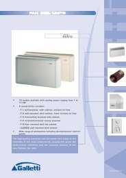
FIGURE 1<br />
Ambient Coil<br />
Refrigerant Circuit No 2<br />
REFRIGERANT FLOW DIAGRAM - COOLING MODE<br />
TEV<br />
NRV<br />
OPEN<br />
CLOSED<br />
High pressure<br />
sub-cooled liquid<br />
High Pressure<br />
superheated vapour<br />
Compressor<br />
Accumulator<br />
OPEN CLOSED<br />
3-Way Valve<br />
OPEN<br />
Cooling Mode<br />
Low pressure liquid refrigerant enters the<br />
refrigerant to water heat exchanger and is<br />
evaporated and superheated by the heat<br />
energy absorbed from the chilled water<br />
passing through the heat exchanger shell.<br />
Low pressure vapour passes through the<br />
three way valve and accumulator before<br />
entering the compressor where pressure<br />
and superheat are increased. Heat is<br />
rejected via the ambient coil and fans.<br />
The fully condensed and subcooled liquid<br />
refrigerant then enters the expansion<br />
valve where pressure reduction and<br />
further cooling takes place before<br />
returning to the heat exchanger.<br />
Low pressure superheated vapour<br />
TEV<br />
Low pressure<br />
sub-cooled<br />
liquid<br />
Refrigerant Circuit No 2<br />
Refrigerant to Water<br />
Heat Exchanger<br />
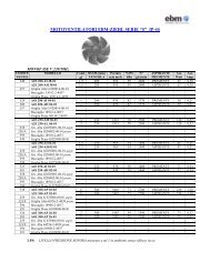
Heating Mode<br />
Liquid refrigerant enters the ambient coil<br />
and is fully evaporated and superheated<br />
by the energy absorbed from the ambient<br />
air. Low pressure superheated refrigerant<br />
vapour passes through the three way<br />
valve and accumulator and enters the<br />
compressor, where pressure and<br />
superheat are increased. High pressure<br />
superheated refrigerant vapour enters the<br />
refrigerant to water heat exchanger tubes<br />
where heat is rejected to the water<br />
circulating through the shell. The high<br />
pressure liquid refrigerant, leaving the<br />
heat exchanger, enters the thermostatic<br />
expansion valves where the refrigerant<br />
pressure is reduced and subsequently<br />
cooled before returning to the ambient<br />
coil.<br />
Defrost Mode<br />
When ice builds up on the ambient coils<br />
defrost is initiated by operating the<br />
machine in a cooling mode. Each of the<br />
two refrigerant circuits will be defrosted<br />
one at a time. When defrost is operative<br />
the circuit operating in heat pump mode is<br />
in balance with the circuit operating in<br />
defrost (cooling). Therefore, heat energy<br />
is not removed from the hot water system.<br />
FIGURE 2<br />
Ambient Coil<br />
Refrigerant Circuit No 2<br />
Low pressure TEV<br />
sub-cooled<br />
liquid<br />
REFRIGERANT FLOW DIAGRAM - <strong>HEAT</strong>ING MODE<br />
High pressure<br />
sub-cooled liquid<br />
NRV<br />
TEV<br />
CLOSED<br />
OPEN<br />
Low pressure superheated vapour<br />
Compressor<br />
High Pressure<br />
superheated vapour<br />
Refrigerant Circuit No 2<br />
Refrigerant to Water<br />
Heat Exchanger<br />
Accumulator<br />
OPEN<br />
OPEN<br />
3-Way Valve<br />
CLOSED<br />
Page K.4<br />
Doc. No. PC142/08.04/GB
DATA REQUIRED<br />
To select a YORK YRHP Reverse Cycle Heat Pump-Chiller, the<br />
following information is required:<br />
1. Required cooling/heating capacity.<br />
2. Design chilled liquid entering and leaving temperatures.<br />
3. Design hot liquid leaving temperature.<br />
4. Design liquid flow rate if one of the temperatures in item 2 are<br />
unknown.*<br />
5. Summer and winter design entering air temperatures.<br />
6. Altitude above sea level.<br />
7. Design refrigerant/water heat exchanger water side fouling<br />
factor.<br />
*Item 4:The same refrigerant to water heat exchanger is used for<br />
chilled liquid in the summer and hot liquid in the winter. The<br />
YRHP cooling capacity normally exceeds the heating capacity at<br />
design ambient conditions. Therefore the water flow should be<br />
calculated using items 1 and 2 and the following formulae:<br />
Cooling capacity kW = l/s chilled liquid x °C range<br />
0.2392<br />
Where:<br />
Range = Entering liquid temperature - Leaving liquid<br />
temperature.<br />
The hot liquid range is calculated as follows:<br />
Hot liquid range °C = Heating capacity x 0.2392<br />
l/s hot liquid<br />
<strong>REVERSE</strong> <strong>CYCLE</strong> <strong>HEAT</strong> <strong>PUMP</strong>-<strong>CHILLER</strong> SELECTION<br />
1. Determine the correct size of unit by selecting the model<br />
which most closely matches the required capacity at the<br />
design conditions of leaving liquid temperatures and entering<br />
air temperatures (Tables 5 and 6).<br />
2. Apply the relevant correction factors for fouling factors and<br />
altitude (Tables 3 and 4) to the cooling and heating capacities<br />
and power values (Tables 5 and 6). Ensure the corrected<br />
capacity is still sufficient for requirements.<br />
3. Using the corrected capacity of the selected unit adjust the<br />
design temperature range, or flow rate, to balance the<br />
formulae shown in "Data Required".<br />
4. Physical and electrical data can now be determined from<br />
Tables 8 and 9.<br />
5. Always re-check that selections fall within the design<br />
limitations specified (Table 2).<br />
FOULING FACTORS TABLE 3<br />
Refrigerant to Water Heat Exchanger<br />
Fouling Factor m² °C/kW Capacity Factor Power Factor<br />
0.044 1.000 1.000<br />
0.088 0.987 0.995<br />
0.176 0.964 0.985<br />
0.352 0.995 0.962<br />
ALTITUDE FACTORS TABLE 4<br />
Altitude (m) Capacity Factor Power Factor<br />
0 1.000 1.000<br />
600 0.987 1.010<br />
1200 0.973 1.020<br />
1800 0.958 1.029<br />
2400 0.943 1.038<br />
SELECTION GUIDE<br />
YRHP SAMPLE SELECTION<br />
A YRHP Reverse Cycle Heat Pump-Chiller operating at 35°C<br />
ambient, is required to cool liquid from 12°C to 7°C having a<br />
cooling capacity of 440 kW. A heating capacity of 300 kW is<br />
required at design conditions of 0°C ambient and a leaving hot<br />
liquid temperature of 45 °C.<br />
The liquid fouling factor is 0.044 m² °C/kW and the unit will be<br />
operating at sea level.<br />
A model YRHP0495 gives approximately the required capacity<br />
(table 5). No correction factors apply, therefore, after calculating<br />
the flow rate, the conditions will be as follows:<br />
Cooling capacity<br />
= 445 kW<br />
Cooling mode input power = 154 kW<br />
Chilled liquid temperature = 12°C to 7°C (5°C range)<br />
Chilled and hot liquid flow rate = 21.3 l/s<br />
Heating capacity<br />
= 317 kW<br />
Heating mode input power = 133kW<br />
Hot leaving temperature = 45°C<br />
Hot liquid range = 3.6 °C<br />
Return hot liquid temperature = 41.4 °C.<br />
All values are within the operating limits in Table 2.<br />
From figure 3 pressure drop = 32.2 kPa at 21.3 l/s.<br />
REFRIGERANT/WATER <strong>HEAT</strong> FIGURE 3<br />
EXCHANGER PRESSURE DROP GRAPH<br />
Pressure Drop (kPa)<br />
120<br />
110<br />
100<br />
90<br />
80<br />
70<br />
60<br />
50<br />
45<br />
40<br />
35<br />
30<br />
25<br />
20<br />
15<br />
10<br />
5<br />
5 10 15 20 25 30 35 40 45<br />
Flow Rate (l/s)<br />
Model<br />
0395<br />
0465<br />
0495<br />
0565<br />
0635<br />
Pressure Drop Calculation<br />
Pressure Drop [kPa] = 0.1057 x (Flow Rate [l/s] 1.8697 )<br />
Pressure Drop [kPa] = 0.0850 x (Flow Rate [l/s] 1.9362 )<br />
Page K.5<br />
Doc. No. PC142/08.04/GB
OPERATION RECOMMENDATIONS<br />
The following recommendations ensure that the maximum cooling/heating duty of the unit is obtained quickly and that nuisance trips<br />
are prevented:<br />
When starting the unit in the ‘Cooling Mode’ or changing from ‘Heating‘ to ‘Cooling’ the operation of any cooling appliance within the<br />
circuit must be inhibited/bypassed, until the chilled liquid returning to the unit has fallen to 20°C.<br />
When starting the unit in the ‘Heat Pump Mode’ or changing from ‘Cooling’ to ‘Heating‘ the operation of any heating appliance within<br />
the circuit must be inhibited/bypassed, until the warm liquid returning to the unit has risen to 35°C.<br />
TABLE 5<br />
YRHP COOLING CAPACITIES<br />
Ambient Coil Entering Air Temperature oC<br />
LWT 20 25 30 35 38 40<br />
42<br />
Model<br />
o C Cool Power Cool Power Cool Power Cool Power Cool Power Cool Power Cool Power<br />
kW kW kW kW kW kW kW kW kW kW kW kW kW kW<br />
5 451 120 430 125 402 131 371 136 354 138 336 140 318 142<br />
6 469 122 445 126 416 132 385 138 364 140 349 142 334 144<br />
YRHP 7 486 124 460 128 429 134 399 139 374 143 363 144 349 146<br />
0395 8 502 126 478 130 448 136 420 143 386 145 378 150 255 148<br />
10 520 130 495 134 468 139 441 145 406 147 392 149 265 99<br />
12 539 134 514 138 489 142 463 147 427 150 284 100 276 101<br />
5 520 150 496 156 464 163 428 170 408 173 388 175 367 178<br />
6 541 153 513 158 479 165 444 172 420 175 403 177 386 180<br />
YRHP 7 561 155 530 160 495 167 460 174 431 178 419 180 403 182<br />
0465 8 579 158 551 163 517 170 485 178 445 181 436 188 294 122<br />
10 600 162 571 167 540 174 509 181 468 184 452 186 306 124<br />
12 622 167 593 172 564 178 534 184 493 187 327 125 318 126<br />
5 571 146 543 151 514 158 486 165 457 170 434 175 413 177<br />
6 594 147 561 153 528 159 495 167 470 172 452 175 434 179<br />
YRHP 7 617 149 580 155 544 161 504 169 483 174 469 177 454 181<br />
0495 8 650 152 611 158 571 164 520 172 507 177 489 180 304 184<br />
10 680 158 642 164 600 171 557 178 530 183 508 186 328 190<br />
12 712 165 671 171 629 178 594 185 555 189 527 192 500 196<br />
5 629 168 594 176 559 185 507 192 493 195 483 198 473 201<br />
6 653 171 615 180 578 188 526 195 507 198 494 202 483 205<br />
YRHP 7 678 175 635 183 596 191 544 198 522 202 507 206 493 209<br />
0565 8 701 179 658 186 615 194 563 202 538 207 521 210 514 213<br />
10 748 185 699 193 651 201 598 208 568 213 536 215 407 154<br />
12 797 192 742 199 688 202 633 215 599 219 449 155 436 159<br />
5 683 205 646 215 608 225 551 234 536 238 525 241 514 244<br />
6 710 209 668 219 628 229 571 238 551 242 537 246 525 249<br />
YRHP 7 736 214 691 223 648 233 592 242 567 246 551 249 536 253<br />
0635 8 762 218 715 227 668 236 612 246 584 253 566 259 411 194<br />
10 813 226 760 235 708 245 650 254 617 260 462 195 443 198<br />
12 866 234 807 243 748 252 689 262 652 267 489 200 474 205<br />
Performance with capacity set-back due to head pressure control. Set-back will also occur at all<br />
ambient exceeding 42°C.<br />
Fans are factory set to operate at low speed at 10 barg refrigerant discharge pressure. This is generally<br />
when operating at all ambients below 20°C.<br />
Fan operation/staging is controlled by head pressure, at ambients below 35°C all fans may not operate.<br />
The total unit fan power, when fans are operating at full speed, is 8 kW for YRHP 0395 and 0465,<br />
or 10.5 kW for YRHP 0495, 0565 and 0635.<br />
Power kW is compressor power only.<br />
Page K.6<br />
Doc. No. PC142/08.04/GB
YRHP <strong>HEAT</strong>ING CAPACITIES TABLE 6<br />
Ambient Coil Entering Air Temperature o C<br />
-6<br />
-4<br />
-2<br />
0<br />
2<br />
4<br />
6<br />
8<br />
10<br />
12<br />
14<br />
16<br />
18<br />
Model YRHP 0395 YRHP 0465 YRHP 0495 YRHP 0565 YRHP 0635<br />
LHLT °C 35 40 45 50 35 40 45 50 35 40 45 50 35 40 45 50 35 40 45 50<br />
Heat kW 216 206 197 259 247 236 266 254 243 301 286 274 360 343 328<br />
Power kW 79 81 83 120 124 127 120 123 126 133 137 140 165 170 174<br />
Heat kW 236 226 217 284 271 260 292 279 267 329 315 301 394 377 361<br />
Power kW 98 101 103 122 125 129 121 125 128 134 138 142 167 172 177<br />
Heat kW 257 247 236 226 308 296 284 271 317 304 292 278 357 343 329 314 428 411 394 376<br />
Power kW 100 102 105 109 124 128 131 135 123 127 130 135 137 141 145 149 170 175 180 186<br />
Heat kW 278 255 257 245 333 321 308 294 343 330 317 303 387 372 357 342 463 446 428 409<br />
Power kW 101 104 107 111 126 130 134 138 126 129 133 137 139 143 148 153 173 178 184 190<br />
Heat kW 304 293 281 271 364 351 338 325 374 361 347 334 423 407 392 377 506 488 469 451<br />
Power kW 103 106 110 114 129 133 137 143 128 132 136 142 142 146 151 157 177 182 188 196<br />
Heat kW 333 320 308 296 400 384 369 356 411 395 380 366 463 446 428 412 555 534 513 494<br />
Power kW 106 109 114 118 133 136 142 147 132 135 141 146 146 150 157 162 182 187 195 202<br />
Heat kW 363 349 337 325 436 418 405 390 448 430 416 401 505 485 469 453 605 581 562 461<br />
Power kW 110 113 118 122 137 141 148 153 136 140 147 152 151 156 163 168 188 194 203 172<br />
Heat kW 397 379 368 356 477 455 441 427 490 468 454 439 553 528 512 421 662 632 613 504<br />
Power kW 114 118 123 128 142 147 154 160 141 146 153 159 157 162 170 146 195 202 212 181<br />
Heat kW 426 410 395 326 511 492 474 392 525 506 487 403 593 571 549 454 710 684 658 544<br />
Power kW 118 123 129 111 147 153 161 138 146 152 160 137 162 169 178 153 202 211 222 190<br />
Heat kW 449 433 418 345 539 519 501 414 554 534 515 426 625 602 581 480 748 721 696 575<br />
Power kW 122 128 135 116 153 160 168 145 152 159 167 144 168 176 186 160 210 220 232 199<br />
Heat kW 472 455 439 362 566 546 527 434 582 561 542 446 656 633 611 504 786 758 732 603<br />
Power kW 127 133 140 121 158 167 176 151 157 166 174 150 175 184 194 167 218 230 242 208<br />
Heat kW 494 477 461 380 593 572 554 456 610 588 569 468 688 664 642 529 824 795 769 633<br />
Power kW 131 139 146 126 164 174 183 158 163 173 182 157 181 192 202 174 226 240 253 217<br />
Heat kW 517 499 483 468 621 599 580 562 638 616 596 577 720 695 672 554 862 832 805 663<br />
Power kW 135 145 152 159 169 181 191 200 168 180 189 198 187 200 210 181 233 250 263 226<br />
Maximum hot leaving liquid temperature of 45°C to prevent excessive discharge temperatures.<br />
468 Unit capacity and power reduced due to high discharge pressure limiting.<br />
At ambient temperatures less than +4°C defrost operation is included in the data and capacities are therefore<br />
an average of normal operation and defrost.<br />
Defrost operates on one refrigerant circuit at a time. The fans of the circuit being defrosted do not operate.<br />
At 0°C ambient dry bulb and 85% relative humidity defrost occurs for a total of 6 minutes in each hour.<br />
High speed fan operation can be inhibited manually, at the unit, or remotely.<br />
Low speed fan operation will reduce the heating capacity by 5% and increase the total kW input by 2%<br />
(due to increases in compressor power minus 4.8 kW reduction in fan power).<br />
SOUND POWER DATA TABLE 7<br />
Model YRHP<br />
0395 0465 0495 0565 0635<br />
Standard Unit Fans at Nominal Low Speed (705 rpm) 96 96 97 97 97<br />
Fans at Nominal High Speed 540 rpm) 98 98 99 99 99<br />
Low Sound Unit Fans at Nominal Low Speed (705 rpm) 88 88 89 89 89<br />
Fans at Nominal High Speed 540 rpm) 92 92 93 93 93<br />
Sound Power has been calculated from sound pressure measurements in free field conditions.<br />
Page K.7<br />
Doc. No. PC142/08.04/GB
TABLE 8<br />
PHYSICAL DATA<br />
YRHP<br />
0395 0465 0495 0565 0635<br />
Number of refrigerant circuits<br />
2 2 2 2 2<br />
Unit refrigerant charge (per circuit = Unit / 2)<br />
kg 110 110 130 130 130<br />
Model<br />
PC632Q PC642S PC642S PC833S PC843T<br />
Quantity 2 2 2 2 2<br />
Compressor<br />
Number of cylinders each 6 6 6 8 8<br />
Speed rpm 1450 1450 1450 1450 1450<br />
Oil capacity each I 13.3 13.3 13.3 13.3 13.3<br />
Unit capacity steps 6 6 6 8 8<br />
Model 790 790 920 920 920<br />
Heat Exchanger<br />
Quantity 1 1 1 1 1<br />
Number of circuits 2 2 2 2 2<br />
Water capacity I 230 230 214 214 214<br />
Ambient Coil<br />
Face area m 2 17.84 17.84 23.78 23.78 23.78<br />
Nuber of tube rows 4 4 4 4 4<br />
Number of fans 6 6 8 8 8<br />
Nominal high speed rpm 705 705 705 705 705<br />
Fans<br />
Total air flow at high speed m 3 /s 37.5 37.5 50 50 50<br />
Nominal low speed rpm 540 540 540 540 540<br />
Total air flow at low speed m 3 /s 30 30 40 40 40<br />
Weight<br />
Shipping kg 5590 5590 6380 6380 6380<br />
Operating kg 5820 5820 6594 6594 6594<br />
Length mm 6021 6021 7240 7240 7240<br />
Dimensions (1) Width mm 2330 2330 2330 2330 2330<br />
Height mm 2489 2489 2489 2489 2489<br />
(1) Length does not include door interlocked disconnect switch/circuit breaker handles.<br />
(1) Width does not include drip trays or header enclosure.<br />
(1) Height does not include anti-vibration mounts.<br />
TABLE 9<br />
ELECTRICAL DATA<br />
Nominal Running Amps Maximum Running Amps<br />
Locked Rotor Conditions (2)<br />
@ 380 V @ 400 V @ 380 V @ 400 V @Min.V (1)<br />
Star for Star/Delta Part Wind<br />
Model<br />
Without Power Factor Correction<br />
Current Amps Current Amps<br />
YRHP With Optional Power Factor Correction fitted<br />
@ 380V @ 400V @ 380V @ 400V<br />
0395<br />
0465<br />
0495<br />
0565<br />
0635<br />
261<br />
325<br />
324<br />
350<br />
438<br />
263<br />
321<br />
322<br />
346<br />
430<br />
333<br />
381<br />
414<br />
434<br />
518<br />
327<br />
373<br />
404<br />
422<br />
502<br />
392<br />
442<br />
491<br />
519<br />
603<br />
229<br />
289<br />
290<br />
316<br />
392<br />
223<br />
281<br />
280<br />
306<br />
378<br />
301<br />
347<br />
378<br />
400<br />
470<br />
291<br />
333<br />
364<br />
384<br />
450<br />
346<br />
394<br />
439<br />
463<br />
535<br />
207<br />
247<br />
247<br />
247<br />
304<br />
218<br />
260<br />
260<br />
260<br />
320<br />
458<br />
549<br />
549<br />
549<br />
689<br />
482<br />
578<br />
578<br />
578<br />
725<br />
Note: (1) Voltage limits (Min. V) on units without Power Factor Correction is 342-440 V<br />
Note: (1) Voltage limits (Min. V) on units with Optional Power Factor Correction is 360-440 V<br />
Figures in table based on the higher of the two modes - Nominal: Cooling, - Maximum: Heating<br />
Note: (2) Locked rotor conditions are per compressor<br />
Page K.8<br />
Doc. No. PC142/08.04/GB
ELECTRICAL CONNECTIONS - POWER SUPPLIES<br />
Standard Single Point Power Supply<br />
One supply to master non-fused disconnect switch (XCSISD)<br />
with internal power distribution to fuses, control supply to non-fused<br />
disconnect switch (QCSD/ESD) derived internally.<br />
1PS<br />
FFF<br />
2PS<br />
CIS<br />
FFF<br />
QCSISD<br />
U V W<br />
QCSD/ESD<br />
PE 3 4<br />
PE<br />
L1 L2 L3<br />
QRESB<br />
3 50 Hz 380/400 V<br />
DESIGNATION<br />
AMB<br />
ARB<br />
CS<br />
CIS<br />
F<br />
PE<br />
PS<br />
QCSD/ESD<br />
QCB<br />
QCSISD<br />
QCSITB<br />
QRESB<br />
QSDF<br />
EMS<br />
DESCRIPTION<br />
MICROPROCESSOR BOARD<br />
RELAY BOARD<br />
CONTROL SECTION<br />
COMMOMN INPUT SECTION<br />
FUSE<br />
PROTECTIVE EARTH<br />
POWER SECTION<br />
CONTROL CIRCUIT SWITCH DISCONNECT<br />
/ EMERGENCY STOP DEVICE<br />
CIRCUIT BREAKER<br />
COMMON SUPPLY INPUT SWITCH DISCONNECT<br />
COMMON SUPPLY INPUT TERMINAL BLOCK<br />
REMOTE EMERGENCY STOP BUTTON<br />
SWITCH DISCONNECT FUSED<br />
EMS INTERFACE CARD (OPTION)<br />
Single Point Power Supply (Option)<br />
One supply to a common terminal block (QCSITB) with<br />
internal power distribution to fused disconnect switches (QSDF)<br />
or circuit breakers (QCB),<br />
control supply to non-fused<br />
disconnect switch (QCSD/ESD) derived internally.<br />
Single Point Power Supply (Option)<br />
One supply to master non-fused disconnect switch (QCSISD)<br />
with internal power distribution to fused disconnect<br />
switches (QSDF) or circuit breaker (QCB),<br />
control supply<br />
to non-fused disconnect switch (QCSD/ESD) derived internally.<br />
1PS<br />
2PS<br />
1PS<br />
2PS<br />
QSDF/QCB<br />
CIS<br />
QSDF/QCB<br />
QSDF/QCB<br />
CIS<br />
QSDF/QCB<br />
U V W<br />
QCSITB<br />
U V W<br />
U V W<br />
QCSISD<br />
U V W<br />
U V W<br />
PE<br />
QCSD/ESD<br />
3 4<br />
U V W<br />
PE<br />
QCSD/ESD<br />
3 4<br />
L1 L2 L3<br />
PE<br />
QRESB<br />
L1 L2 L3<br />
PE<br />
QRESB<br />
3 50 Hz 380/400 V<br />
3 50 Hz 380/400 V<br />
Multi Point Power Supply (Option)<br />
Two supplies to fused disconnect switches (QSDF) or circuit breakers (QCB)<br />
with separate control supply to non-fused disconnect switch (QCSD/ESD).<br />
+5V<br />
GND<br />
RXD<br />
TXD<br />
DSR<br />
DTR<br />
RS232<br />
1PS<br />
CS<br />
AMB ARB<br />
EMS<br />
2PS<br />
QSDF<br />
or<br />
QCB<br />
CIS<br />
3<br />
4<br />
QSDF<br />
or<br />
QCB<br />
PE<br />
U V W<br />
PE<br />
QCSD/ESD<br />
PE<br />
U V W<br />
QRESB<br />
PE<br />
L1 L2<br />
3 50Hz<br />
380/400V<br />
L3<br />
PE<br />
L1 L3<br />
2 50Hz<br />
380/400V<br />
PE<br />
L1 L2 L3<br />
3 50Hz<br />
380/400V<br />
Page K.9<br />
Doc. No. PC142/08.04/GB
ELECTRICAL CONNECTIONS - CONTROL<br />
1PS<br />
CS<br />
AMB<br />
CIS<br />
ARB<br />
EMS<br />
2PS<br />
34<br />
33<br />
36<br />
35<br />
37<br />
38<br />
39<br />
30<br />
31<br />
32<br />
41<br />
40<br />
}<br />
}<br />
}<br />
}<br />
}<br />
}<br />
}<br />
Liquid Pump Start<br />
Unit Run Signal<br />
Open on Alarm<br />
Close on Alarm<br />
Open on Alarm<br />
Close on Alarm<br />
Bivalent Heat Signal<br />
}<br />
}<br />
System<br />
N° 1<br />
System<br />
N° 2<br />
16 13 14 13 17 15 13 11 13 12 10 13<br />
Flow Switch<br />
System 2 Remote Run Interlock<br />
Fan Full Speed Inhibit<br />
System 1 Remote Run Interlock<br />
PWM Remote Temperature Reset or<br />
Remote Unload Second Stage<br />
Remote Mode Selection Closed for Heating<br />
Remote Unload First Stage<br />
SPACE REQUIREMENTS<br />
2.0 m<br />
1.3 m<br />
1.3 m<br />
2.0 m<br />
2.0 m<br />
2.0 m<br />
2.0 m<br />
2.0 m<br />
1.3 m<br />
2.0 m 3.0 m<br />
2.0 m<br />
2.0 m<br />
2.0 m<br />
Page K.10<br />
Doc. No. PC142/08.04/GB
DIMENSIONS<br />
YRHP 0395 and 0465<br />
523<br />
2330<br />
761<br />
1118<br />
CL<br />
VESSEL<br />
VIEW A<br />
SEE DETAIL A<br />
VIEW B<br />
A<br />
2169<br />
2489<br />
B<br />
2694<br />
2224<br />
INLET<br />
SEE DETAIL B<br />
6021<br />
12 HOLES Ø 22 EQUI. SPACED<br />
ON P.C.D. OF 295mm<br />
OUTLET<br />
SEE DETAIL B<br />
Ø 340<br />
Ø 209,1<br />
DETAIL A<br />
POWER SUPPLY CABLE ENTRY<br />
GLAND PLATE 286 X 235<br />
2 x DIN 200/PIN 16<br />
DETAIL B<br />
Page K.11<br />
Doc. No. PC142/08.04/GB
DIMENSIONS (continued)<br />
YRHP 0495, 0565 and 0635<br />
523<br />
2330<br />
761<br />
1118<br />
CL<br />
VESSEL<br />
VIEW A<br />
SEE DETAIL A<br />
VIEW B<br />
A<br />
2169<br />
2489<br />
B<br />
2694<br />
2224<br />
INLET<br />
SEE DETAIL B<br />
7240<br />
12 HOLES Ø 22 EQUI. SPACED<br />
ON P.C.D. OF 295mm<br />
OUTLET<br />
SEE DETAIL B<br />
Ø 340<br />
Ø 209,1<br />
DETAIL A<br />
POWER SUPPLY CABLE ENTRY<br />
GLAND PLATE 286 X 235<br />
2 x DIN 200/PIN 16<br />
DETAIL B<br />
Page K.12<br />
Doc. No. PC142/08.04/GB