User's Manual for VariSpec - PerkinElmer
User's Manual for VariSpec - PerkinElmer
User's Manual for VariSpec - PerkinElmer

You also want an ePaper? Increase the reach of your titles
YUMPU automatically turns print PDFs into web optimized ePapers that Google loves.
<strong>VariSpec</strong><br />
LIQUID CRYSTAL TUNABLE FILTERS<br />
User’s <strong>Manual</strong> <strong>for</strong> <strong>VariSpec</strong><br />
Seeing life in a new light
Notice<br />
The in<strong>for</strong>mation in this document is subject to change without notice and should not be construed as a commitment<br />
by Cambridge Research & Instrumentation, Inc. CRi assumes no responsibility <strong>for</strong> any errors that may appear in<br />
this document. This manual is believed to be complete and accurate at the time of publication. In no event shall<br />
CRi be liable <strong>for</strong> incidental or consequential damages in connection with or arising from the use of this manual.<br />
For more in<strong>for</strong>mation contact:<br />
Cambridge Research & Instrumentation, Inc. (CRi)<br />
35-B Cabot Road, Woburn, MA, 01801, USA<br />
(Toll-Free US) 1-800-383-7924, (Phone) +1-781-935-9099, (Fax) +1-781-935-3388<br />
Email: techsupport@cri-inc.com<br />
Web site: http://www.cri-inc.com<br />
Document Part No. MD15474 Rev. D, August 2010<br />
CRi, 35-B Cabot Road, Woburn, MA, 01801, USA :: (Toll-Free US) 1-800-383-7924, (P) +1-781-935-9099, (F) +1-781-935-3388 :: sales@cri-inc.com :: www.cri-inc.com
Contents<br />
Chapter 1, Introduction to <strong>VariSpec</strong> Liquid Crystal Tunable Filters 1<br />
Introduction...........................................................................................................................................................1<br />
Important Features................................................................................................................................................2<br />
Applications..........................................................................................................................................................2<br />
Glossary of <strong>VariSpec</strong> LCTF Terminology ...........................................................................................................3<br />
Operator and Equipment Safety............................................................................................................................4<br />
Cautionary Statements ...................................................................................................................................4<br />
For Technical Assistance ...............................................................................................................................4<br />
About This <strong>Manual</strong>...............................................................................................................................................4<br />
Design Change Disclaimer.............................................................................................................................5<br />
Reproduction Disclaimer ...............................................................................................................................5<br />
CE Testing and Certification ................................................................................................................................5<br />
<strong>VariSpec</strong> Hardware Components .........................................................................................................................6<br />
<strong>VariSpec</strong> Filter Module..................................................................................................................................7<br />
USB Peripheral Type-A to Mini-B Cable......................................................................................................7<br />
<strong>VariSpec</strong> XNIR-09-20 Electronics Controller Module..................................................................................7<br />
Optics-to-Electronics Cable ...........................................................................................................................8<br />
Mounting Block .............................................................................................................................................8<br />
Mounting Inserts (optional accessory)...........................................................................................................8<br />
52 mm Camera Lens Thread Adapter (optional accessory)...........................................................................8<br />
<strong>VariSpec</strong> Software Developer’s Kit (SDK) installation CD ................................................................................9<br />
Chapter 2, Setting Up a <strong>VariSpec</strong> Filter 11<br />
Unpacking the <strong>VariSpec</strong> Filter and Accessories ................................................................................................11<br />
Installing the <strong>VariSpec</strong> Software........................................................................................................................12<br />
Connecting the <strong>VariSpec</strong> Filter (except XNIR-09-20 models) ..........................................................................12<br />
Connecting XNIR-09-20 Dual-Housing Filter Models ......................................................................................13<br />
VsGui Program <strong>for</strong> Windows XP and Windows 7.............................................................................................15<br />
Chapter 3, Controlling <strong>VariSpec</strong> Filters 17<br />
Components of the <strong>VariSpec</strong> SDK.....................................................................................................................17<br />
Windows DLL..............................................................................................................................................17<br />
National Instruments® LabVIEW Sub-VIs .............................................................................................18<br />
MATLAB® M-Files ....................................................................................................................................18<br />
VsGui Program <strong>for</strong> Windows XP Professional and Windows 7 (32-bit) ....................................................18<br />
Controlling <strong>VariSpec</strong> Filters with Direct Serial Commands ..............................................................................18<br />
Initialization .................................................................................................................................................18<br />
Palette Commands........................................................................................................................................19<br />
<strong>VariSpec</strong> XNIR-09-20 TTL Sync Port ........................................................................................................19<br />
LED Behavior ..............................................................................................................................................20<br />
Putting the <strong>VariSpec</strong> Filter to Sleep.............................................................................................................20<br />
Escape, Status-Check, and Busy-Check Characters ....................................................................................20<br />
Command Nomenclature .............................................................................................................................21<br />
Brief and Auto-Confirm Formats.................................................................................................................21<br />
Table of Commands .....................................................................................................................................22<br />
Descriptions of <strong>VariSpec</strong> Serial Commands................................................................................................22<br />
Error Codes.........................................................................................................................................................27<br />
Contents — i
Programming Examples......................................................................................................................................28<br />
Example 1. Tuning by wavelength...............................................................................................................28<br />
Example 2. Tuning with a palette ................................................................................................................29<br />
Example 3. Cycling through various wavelengths using the TTL Sync port on the XNIR-09-20..............30<br />
Controlling <strong>VariSpec</strong> Filters with Other Operating Systems .............................................................................30<br />
Chapter 4, Frequently Asked Questions & Troubleshooting 31<br />
FAQs...................................................................................................................................................................31<br />
Appendix A, System Specifications & Dimensions 37<br />
Operating Specifications.....................................................................................................................................37<br />
Mechanical Dimensions (Optics Module)..........................................................................................................38<br />
<strong>VariSpec</strong> 22 mm Aperture Standard Enclosure ...........................................................................................38<br />
<strong>VariSpec</strong> 22 mm Aperture Dual-Housing Enclosure...................................................................................38<br />
<strong>VariSpec</strong> 22 mm Aperture Enclosure <strong>for</strong> the XNIR-09-20 Model.............................................................39<br />
<strong>VariSpec</strong> Mounting Adapters <strong>for</strong> 22 mm Aperture Models.........................................................................40<br />
Standard 22 mm Aperture Filter Mounting Block .......................................................................................42<br />
<strong>VariSpec</strong> 22 mm Aperture Enclosure <strong>for</strong> the LNIR-20-20 Model ..............................................................43<br />
<strong>VariSpec</strong> 35 mm Aperture Enclosure ..........................................................................................................43<br />
Dovetail Spacer ............................................................................................................................................44<br />
Dovetail C-Mounts.......................................................................................................................................44<br />
Electronics Controller Module ...........................................................................................................................46<br />
Optics-to-Electronics Cable................................................................................................................................46<br />
Appendix B, Operating Considerations 47<br />
Variation of FWHM with Pass Wavelength.......................................................................................................47<br />
Bandwidth Center Across Angle-of-Acceptance................................................................................................47<br />
Response Time versus Tuning Wavelength .......................................................................................................47<br />
Thermal Drift and Re-Initialization....................................................................................................................47<br />
Response Time versus Temperature...................................................................................................................48<br />
Fringing in Coherent Light .................................................................................................................................48<br />
Tuning Latency...................................................................................................................................................48<br />
Near-Infrared Warning .......................................................................................................................................48<br />
Using HyperTerminal <strong>for</strong> <strong>Manual</strong> Control .....................................................................................................49<br />
Appendix C, Legacy Hardware and Software Considerations 51<br />
Optics and Electronics Controller Modules........................................................................................................51<br />
Handheld Controller ...........................................................................................................................................51<br />
Legacy Software .................................................................................................................................................51<br />
Appendix D, CRi Software End-User License Agreement 53<br />
Appendix E, <strong>VariSpec</strong> Quick Start Guide 57<br />
Index 59<br />
ii — Contents
Chapter 1<br />
Introduction to <strong>VariSpec</strong> Liquid<br />
Crystal Tunable Filters<br />
This chapter provides in<strong>for</strong>mation about <strong>VariSpec</strong> liquid crystal tunable filters (LCTFs)<br />
that is common to all filter models. Appendices are used to provide additional in<strong>for</strong>mation,<br />
specific to individual models.<br />
Topics in this chapter:<br />
Page<br />
• Important Features ............................................................................................... 2<br />
• Applications......................................................................................................... 2<br />
• Glossary of <strong>VariSpec</strong> LCTF Terminology........................................................... 3<br />
• Operator and Equipment Safety........................................................................... 4<br />
• About This <strong>Manual</strong> .............................................................................................. 4<br />
• CE Testing and Certification................................................................................ 5<br />
• <strong>VariSpec</strong> Hardware Components......................................................................... 6<br />
• <strong>VariSpec</strong> Software Developer’s Kit (SDK) installation CD................................ 9<br />
Introduction<br />
CRi’s <strong>VariSpec</strong> LCTF family are solid-state tunable birefringent filters that can be used <strong>for</strong><br />
both imaging and non-imaging spectral analysis. The filters function like high-quality<br />
interference filters, but the wavelengths of light they transmit are electronically tunable<br />
and allow <strong>for</strong> the rapid, vibration-less selection of any wavelength in the visible (VIS) or<br />
near-infrared (NIR) region <strong>for</strong> which the filters have been constructed to operate.<br />
<strong>VariSpec</strong> filters employ electronically controlled liquid crystal elements to select a<br />
transmitted wavelength range while blocking all others. Filter transmittance is sensitive to<br />
polarization of the input beam, and is increased by a factor of two if the input beam is<br />
polarized along the axis of the input polarizer, as compared with a non-polarized or<br />
Introduction to <strong>VariSpec</strong> Liquid Crystal Tunable Filters — 1
Important Features<br />
Applications<br />
randomly-polarized beam. VIS models contain an integral, non-removable hot mirror <strong>for</strong><br />
blocking unwanted NIR light. The product family includes the following models:<br />
• VIS: Visible-wavelength filters with a wavelength range of 400 nm to 720 nm,<br />
bandwidths (FWHM) of 7 nm, 10 nm, or 20 nm, and working apertures of either 22<br />
mm or 35 mm<br />
• SNIR: Short-wavelength near-infrared filters with a wavelength range of 650 nm to<br />
1100 nm, bandwidths (FWHM) of 7 nm or 10 nm, and a working aperture of 22 mm<br />
• LNIR: Longer-wavelength near-infrared filters with a wavelength range of 850 nm<br />
to 1800 nm, bandwidths (FWHM) of 6 nm or 20 nm, and a working aperture of 22<br />
mm<br />
• XNIR: Longer-wavelength near-infrared filter with a wavelength range of 1200 nm<br />
to 2450 nm, bandwidth (FWHM) of 9 nm, and a working aperture of 22 mm<br />
• VISR: Visible-wavelength filter with a wavelength range of 480 nm to 750 nm,<br />
extraordinarily narrow bandwidth (FWHM) of 0.25 nm (best ef<strong>for</strong>t), and a working<br />
aperture of 22 mm<br />
• NIRR: Near-infrared wavelength filter with a wavelength range of 650 nm to 1100<br />
nm, extraordinarily narrow bandwidth (FWHM) of 0.75 nm (best ef<strong>for</strong>t), and a<br />
working aperture of 22 mm<br />
Important features of <strong>VariSpec</strong> filters include:<br />
• Ability to tune continuously over hundreds of nanometers in the VIS and NIR<br />
• Excellent imaging quality<br />
• Solid-state construction, with no moving parts<br />
• Fast, random-access wavelength selection<br />
• Compact, low-power design<br />
<strong>VariSpec</strong> filters offer excellent imaging quality, making them ideal <strong>for</strong> use with imaging<br />
sensors such as silicon-based CCDs or InGaAs sensors. Additionally, they can be used as<br />
compact, robust spectrometers with high throughput, well-suited to applications where<br />
imaging may not even be required. Key applications include:<br />
• Remote Sensing<br />
• Machine vision QA/QC<br />
• Astronomy<br />
• CCD/Display characterization<br />
• Raman chemical imaging<br />
• General research involving spectral imaging<br />
2 — Introduction to <strong>VariSpec</strong> Liquid Crystal Tunable Filters
Glossary of <strong>VariSpec</strong> LCTF Terminology<br />
Bandwidth<br />
The Full-Width at Half-Maximum (FWHM), measured as the spectral separation between<br />
the two points where the filter’s transmission attains 50% of the peak value. The passband<br />
center wavelength is the wavelength midway between these two points. <strong>VariSpec</strong> filters<br />
come in a variety of bandwidths, which are set during the design and manufacturing<br />
process and are not adjustable by the end-user.<br />
Center Wavelength<br />
Not necessarily the highest point in the T curve, this is defined as midway between the<br />
half-maxima points.<br />
Off-Axis Per<strong>for</strong>mance at Limit of Angle-of-Acceptance<br />
Off-axis rays at the limit of the angle-of-acceptance are permitted to be spectrally shifted<br />
by up to Bandwidth/8 from the on-axis ray value. So, in the worst case, the center ray<br />
could have a center wavelength which exceeds the ideal by +Bandwidth/8, and an off-axis<br />
ray could be shifted by +Bandwidth/8 red of that, or +Bandwidth/4 away from the ideal<br />
value.<br />
Out-of-Band Transmittance or Contrast<br />
The average ratio of transmission without the <strong>VariSpec</strong> filter in place to the transmission<br />
of unselected wavelengths with the filter in place. Typical per<strong>for</strong>mance is 0.01%.<br />
Passband<br />
Response Time<br />
Transmission<br />
Tuning Accuracy<br />
The spectral region from [Center Wavelength – 1.2 * FWHM] to [Center Wavelength +<br />
1.2 * FWHM].<br />
The time it takes to switch from one wavelength to another. The major factor that affects<br />
this number is the liquid crystal (LC) relaxation time from “charge” to “no charge” states<br />
under various ambient temperatures. Typically, this time is 50 ms to 150 ms.<br />
The percentage of linearly polarized light, oriented so that maximum transmission is<br />
attained, passing through the filter relative to the amount that entered. Since the entrance<br />
element of the filter is a linear polarizer, transmission of randomly polarized light is half<br />
that of linearly polarized light in the correct orientation. <strong>VariSpec</strong> transmission is<br />
wavelength-dependent.<br />
The tuning accuracy specification is that the center wavelength be correct within the actual<br />
Bandwidth/8 +/- 0.5 nm. Tuning accuracy is specified <strong>for</strong> on-axis rays.<br />
Introduction to <strong>VariSpec</strong> Liquid Crystal Tunable Filters — 3
Operator and Equipment Safety<br />
Cautionary Statements<br />
For Technical Assistance<br />
About This <strong>Manual</strong><br />
It is the responsibility of the purchaser to ensure that all persons who will operate the<br />
<strong>VariSpec</strong> LCTF are aware of the following cautionary statements. As with any scientific<br />
instrument, there are important safety considerations, which are highlighted throughout<br />
this User’s <strong>Manual</strong>.<br />
READ AND UNDERSTAND THIS USER’S MANUAL BEFORE ATTEMPTING<br />
TO OPERATE, TROUBLESHOOT, OR MAINTAIN THE VARISPEC LCTF.<br />
READING THIS MANUAL FIRST MAKES IT EASIER AND SAFER TO<br />
OPERATE AND MAINTAIN THE FILTER.<br />
Do not expose the optics module to prolonged heat above 40 °C.<br />
Do not drop the optics module or the electronics controller module.<br />
Do not expose the optics module to intense light from laser, focused arc or Hg lamp<br />
sources.<br />
Do not operate the filter in places where it may be splashed with liquid. The optics module<br />
may be cleaned using the procedure described in the troubleshooting section of this User’s<br />
<strong>Manual</strong>.<br />
Do not operate the filter in an environment with explosive or flammable gases.<br />
Use only the supplied cables. Some cables supplied with the system have proprietary<br />
specifications. Do not connect components supplied by CRi using unqualified cables or<br />
adapters. Doing so could result in damage, and voids the Warranty.<br />
Use only a host computer that has a properly grounded power outlet.<br />
Disconnect the USB cable and any power cables be<strong>for</strong>e servicing the unit. Servicing<br />
should be per<strong>for</strong>med by CRi authorized and trained personnel only.<br />
If you experience any difficulty setting up, operating, or maintaining your <strong>VariSpec</strong> LCTF,<br />
please contact your CRi representative. CRi’s office hours are from 8:00 a.m. to 6:00 p.m.<br />
(US Eastern Standard/Daylight Time), Monday through Friday.<br />
• Telephone (US Toll-Free): 1-800-383-7924<br />
• Telephone (Worldwide): +1-781-935-9099<br />
• Facsimile (Worldwide): +1-781-935-3388<br />
• Email: techsupport@cri-inc.com.<br />
This manual is designed to serve users of the CRi <strong>VariSpec</strong> LCTF product family.<br />
Operating instructions, functional descriptions, troubleshooting, illustrations, and other<br />
relevant in<strong>for</strong>mation are contained in this manual.<br />
4 — Introduction to <strong>VariSpec</strong> Liquid Crystal Tunable Filters
Design Change Disclaimer<br />
Reproduction Disclaimer<br />
Your particular <strong>VariSpec</strong> LCTF may include additional support documentation from thirdparty<br />
vendors. Bear in mind that the <strong>VariSpec</strong> LCTF may have been modified or customdesigned,<br />
so treat such third-party documentation as supplemental material only. In cases<br />
where CRi and third-party documentation differ, and you have any doubt as to which<br />
applies to your system, contact an authorized CRi distributor or service representative.<br />
Due to design changes and product improvements, in<strong>for</strong>mation in this manual is subject to<br />
change without notice. CRi reserves the right to change product design at any time without<br />
notice to anyone, which may subsequently affect the content of this manual. CRi will<br />
make every reasonable ef<strong>for</strong>t to ensure that this User’s <strong>Manual</strong> is up to date and<br />
corresponds with the <strong>VariSpec</strong> LCTF as currently shipped.<br />
No part of this manual may be reproduced, photocopied, or electronically transmitted,<br />
except <strong>for</strong> reference by a user of the <strong>VariSpec</strong> LCTF, without the advance written<br />
permission of CRi.<br />
CE Testing and Certification<br />
The <strong>VariSpec</strong> LCTF has been tested by an independent CE testing<br />
facility, and bears the appropriate CE mark.<br />
The following is the CRi distributor in the European Union region<br />
authorized to function as primary contact <strong>for</strong> CE-related matters concerning CRi products:<br />
LOT-Oriel GmbH & Co. KG<br />
Im Tiefen See 58<br />
D-64293 Darmstadt<br />
Germany<br />
Tel: +49 6151 88 06 0<br />
Fax: +49 6151 896667<br />
Email: info@lot-oriel.de<br />
Introduction to <strong>VariSpec</strong> Liquid Crystal Tunable Filters — 5
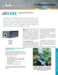
<strong>VariSpec</strong> Hardware Components<br />
<strong>VariSpec</strong> filters consist of either a single module containing both the optics and electronics<br />
assemblies or a matched set of two modules. The XNIR-09-20 model, due to its unique<br />
optical construction, utilizes two matched sets of optics and electronics modules<br />
connected by shielded cables. All <strong>VariSpec</strong> filters draw power from and are controlled by<br />
the Universal Serial Bus (USB) connector of a host computer.<br />
Figure 1. <strong>VariSpec</strong> with 20 mm Optics<br />
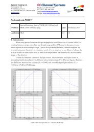
Figure 2. <strong>VariSpec</strong> with 35 mm Optics<br />
6 — Introduction to <strong>VariSpec</strong> Liquid Crystal Tunable Filters
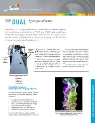
<strong>VariSpec</strong> Filter Module<br />
USB Peripheral Type-A to Mini-B Cable<br />
Figure 3. LNIR-06-20, Dual <strong>VariSpec</strong> with 20 mm Optics<br />
• The entrance aperture receives the light, and <strong>for</strong> VIS models is the side that contains<br />
the integral hot mirror. For filters with a blue and silver housing, the entrance<br />
aperture is the blue side.<br />
• The exit aperture passes linearly polarized light. The orientation is the same or<br />
perpendicular to the input polarizer, depending on the design. For filters with a blue<br />
and silver housing, the exit aperture is the silver side.<br />
• With the exception of the XNIR-09-20 model, the rear panel of the filter module<br />
contains a USB connector and a Status LED.<br />
A USB Type-A to Mini-B cable connects the filter module to the host computer or a<br />
powered USB hub. For the XNIR-09-20 model, a USB Type-A to Type-B cable connects<br />
the <strong>VariSpec</strong> electronics controller module to the host computer or a powered USB hub.<br />
<strong>VariSpec</strong> XNIR-09-20 Electronics Controller Module<br />
The front panel of the XNIR-09-20 electronics controller module (Figure 4) contains an<br />
LED labeled Init and an LED labeled Status.<br />
Figure 4. Front Panel of <strong>VariSpec</strong> Electronics Controller<br />
Introduction to <strong>VariSpec</strong> Liquid Crystal Tunable Filters — 7
Optics-to-Electronics Cable<br />
• Init LED flashes during data communication between the electronics controller<br />
module and the host computer.<br />
• Status LED momentarily flashes Green during power-up and initialization<br />
(approximately 30 seconds).<br />
The rear panel contains four clearly labeled interface ports (left to right, viewed from the<br />
rear).<br />
• Optics A is a 26-pin connector <strong>for</strong> the HD D-sub cable connecting the Optics and<br />
Electronics Controller modules.<br />
• TTL Sync is a connector with a single trigger-detect line that can be configured to<br />
allow the filter to respond to a synchronization pulse generated by cameras, shutters,<br />
and other equipment.<br />
• USB is a “Type-B” USB connector.<br />
• Optics B is not used and has a blank cover.<br />
For the XNIR-09-20 model, a drive signal connector on the optics module connects to its<br />
paired electronics module through a 26-pin high-density (HD) D-sub cable. This cable is<br />
shielded and the present model utilizes twisted-pair construction <strong>for</strong> reduced crosstalk.<br />
WARNING! DO NOT connect a computer, function generator, or other signal source to<br />
this connector, as the liquid crystal elements may be destroyed. Doing so voids the<br />
warranty. The optics module is designed to be driven by the electronics controller module<br />
ONLY. Do not disconnect the cable while the electronics controller module is turned ON.<br />
Mounting Block<br />
Mounting blocks may be attached to three sides of the optics module, to allow the use of<br />
the filters on an optical table or on conventional 1/4-20 UNC-2B threaded tripods. One<br />
mounting block is included per optics module. You may order more if you wish.<br />
Mounting Inserts (optional accessory)<br />
Stainless-steel dovetailed inserts with either male or female C-mount threads or a male T-<br />
mount thread can be placed into the round inset on either the front or rear of the smallaperture<br />
20 mm optics module and held in place with setscrews. By default, a “blank” flat<br />
dovetailed insert with no threaded side is mounted on each side of new filters.<br />
52 mm Camera Lens Thread Adapter (optional accessory)<br />
The 52 mm camera lens thread adapter allows you to convert a male T-mount thread to a<br />
common 52 mm size. This enables you to attach the filter to the front of a camera lens. If<br />
the front of your camera lens is a different diameter, you can purchase “stepping rings”<br />
from camera stores or photographic supply companies to go from the 52 mm thread to<br />
nearly any other thread size. For example, a 62 mm to 52 mm step-down ring lets you<br />
mount the <strong>VariSpec</strong> filter in front of a lens with a 62 mm thread diameter.<br />
8 — Introduction to <strong>VariSpec</strong> Liquid Crystal Tunable Filters
Male T-Mount<br />
Male C-Mount<br />
Female C-Mount<br />
Mounting Block<br />
52 mm Camera Lens<br />
Thread Adapter<br />
Hex Key <strong>for</strong> Set Screws<br />
Figure 5. Mounting Block and Adapters <strong>for</strong> 20 mm Filter<br />
Male T-Mount<br />
Male C-Mount<br />
Female C-Mount<br />
52 mm Camera Lens<br />
Thread Adapter<br />
Mounting Block<br />
Hex Key <strong>for</strong> Set Screws<br />
Figure 6. Mounting Block and Adapters <strong>for</strong> 35 mm Filter<br />
<strong>VariSpec</strong> Software Developer’s Kit (SDK) installation CD<br />
The CD-ROM that comes with each filter is a Windows ® -compatible CD-ROM<br />
containing the following components:<br />
• Windows-compatible operating system installer <strong>for</strong> the CRi SDK<br />
• Apple ® Mac ® OS X drivers <strong>for</strong> the USB interface<br />
• Linux ® drivers <strong>for</strong> the USB interface<br />
• <strong>VariSpec</strong> User’s <strong>Manual</strong> as an Adobe ® PDF file<br />
Introduction to <strong>VariSpec</strong> Liquid Crystal Tunable Filters — 9
10 — Introduction to <strong>VariSpec</strong> Liquid Crystal Tunable Filters
Chapter 2<br />
Setting Up a <strong>VariSpec</strong> Filter<br />
Topics in this chapter:<br />
Page<br />
• Unpacking the <strong>VariSpec</strong> Filter and Accessories................................................ 11<br />
• Installing the <strong>VariSpec</strong> Software ....................................................................... 12<br />
• Connecting the <strong>VariSpec</strong> Filter (except XNIR-09-20 models).......................... 12<br />
• Connecting XNIR-09-20 Dual-Housing Filter Models ..................................... 13<br />
• VsGui Program <strong>for</strong> Windows XP and Windows 7 ............................................ 15<br />
Unpacking the <strong>VariSpec</strong> Filter and Accessories<br />
Upon receiving your <strong>VariSpec</strong> LCTF, carefully unpack the components and compare the<br />
contents against the shipping list. Be careful with the glass surfaces of the optics module,<br />
since they have anti-reflective (AR) coatings that can be scratched if not handled carefully.<br />
Most models include the following items:<br />
• <strong>VariSpec</strong> optics module (you will receive two if you ordered a dual-housing model)<br />
• USB interface cable (Type-A to Mini-B) <strong>for</strong> connecting the filter to your host<br />
computer (you will receive two if you ordered a dual-housing model)<br />
• If you ordered an XNIR-09-20 model, you will receive two electronics controller<br />
modules, two 26-pin HD cables, and two USB interface cables (Type-A to Type-B)<br />
• CD-ROM containing the <strong>VariSpec</strong> software installer<br />
• Additional adapters and mounts <strong>for</strong> optics module(s), if ordered<br />
• <strong>VariSpec</strong> User’s <strong>Manual</strong> in printed <strong>for</strong>m<br />
• Spectral Scan in printed <strong>for</strong>m<br />
Important! Do not connect the <strong>VariSpec</strong> filter to your host computer until you have<br />
installed the appropriate USB drivers.<br />
Setting Up a <strong>VariSpec</strong> Filter — 11
Installing the <strong>VariSpec</strong> Software<br />
CRi supplies a Windows-compatible SDK installation CD-ROM with each <strong>VariSpec</strong> filter.<br />
Included hardware drivers are specific to the Windows operating system. However, you<br />
may contact CRi if you are interested in drivers <strong>for</strong> other operating systems.<br />
Note that these instructions apply to standard single-housing filter designs. Dual-housing<br />
designs have to <strong>VariSpec</strong> modules. The demonstration software does not support dual<br />
module filters. But the existing drivers or LabVIEW sub-VIs can be used to write<br />
programs fully capable of controlling these dual models. You can also use HyperTerminal<br />
or similar terminal emulators to send the appropriate serial (ASCII character-based)<br />
commands to each Varispec module.<br />
Your host computer needs to be running Windows XP or Windows 7. Log in as an<br />
Administrator to install the software. You must have a USB port available and the port<br />
must be able to provide the standard USB power load. If you have multiple USB devices<br />
connected to the same port through an unpowered USB hub, you may need to utilize a<br />
powered hub.<br />
1. DO NOT attach the <strong>VariSpec</strong> filter hardware to the computer yet. Turn on the<br />
computer and allow it to boot into the Windows XP or Windows 7 operating system.<br />
2. Insert the CD-ROM containing the <strong>VariSpec</strong> demonstration and SDK software into<br />
your CD-ROM drive. Or, if you downloaded the installer, open the zip file.<br />
3. Locate the Microsoft installer file, most likely named something similar to<br />
“VsRev1p37.msi” or “VsRev1p37.exe.” Double-click the executable to start the<br />
Installation Wizard.<br />
4. Choose the “Full” installation type. Continue with the Wizard until you can click the<br />
Finish button to complete the installation.<br />
Connecting the <strong>VariSpec</strong> Filter (except XNIR-09-20 models)<br />
1. Connect the <strong>VariSpec</strong> filter to the computer using the included USB Type-A to Mini-B<br />
cable (Figure 7).<br />
Figure 7. Mini USB cable connects to the filter and computer<br />
12 — Setting Up a <strong>VariSpec</strong> Filter
2. The blinking LED indicates that the filter is initializing and exercising the liquid<br />
crystal (LC) elements in the optics module and bringing the filter to a known state. For<br />
example, 550 nm in the case of a visible-wavelength (VIS) model.<br />
3. If this is a first time installation, the computer should launch a Found New Hardware<br />
Wizard. Click the Next button to proceed. (If the wizard did not start automatically,<br />
launch the New Hardware Wizard from the Windows Control Panel.)<br />
4. Choose to “Search <strong>for</strong> a suitable driver <strong>for</strong> my device” and click the Next button. A<br />
Files Needed window may appear. Windows may ask if it can install the software<br />
automatically or from a list or special location. Choose “automatically or the<br />
CDROM/ installation folder” as the search location. Windows should find a file on the<br />
CD-ROM named “ftdibus.inf.” Click Next. Windows should then find a file named<br />
“ftdiport.inf.” Click Next and then click Finish. If Windows cannot find the files, go<br />
back and manually locate the files.<br />
5. After the Add New Hardware Wizard has finished, you will see a new program group<br />
icon appear: Start > Programs > CRi. This program group includes the demonstration<br />
software “VsGui.exe” and a PDF copy of the User’s <strong>Manual</strong>.<br />
Connecting XNIR-09-20 Dual-Housing Filter Models<br />
The host computer must have two available USB ports.<br />
1. Click on the Windows Start button and go to Settings > Control Panel > System.<br />
2. Click on the Hardware tab and then the Device Manager button.<br />
3. Click on the '+' symbol next to the Ports (COM & LPT) list item. Note the COM ports that<br />
you have on your computer. If you have any other serial devices, such as modems,<br />
filter wheels, mice, or keyboards attached to your computer, they will be represented<br />
by a particular COM port.<br />
4. Use a 26-pin HD D-sub cable to connect the <strong>VariSpec</strong> electronics controller module<br />
whose serial number has the suffix “A” to the optics module whose serial number has<br />
suffix “A”. (Refer to Figure 8 on page 14.)<br />
5. Use a second 26-pin HD D-sub cable to connect the electronics module whose serial<br />
number has the suffix “B” to the optics module whose serial number has suffix “B”.<br />
6. Be careful not to bend any of the pins. Tighten the locking screws on both cables.<br />
7. Connect the square end of one of the USB Type-A to Type-B cables to the USB<br />
connector on the rear panel of the electronics module labeled “A”. Connect the<br />
rectangular end of the cable to a USB port on your host computer. (You will connect<br />
the other electronics controller module later.)<br />
Setting Up a <strong>VariSpec</strong> Filter — 13
Figure 8. 26-pin HD D-Sub cables connect to the <strong>VariSpec</strong> optics modules and electronics<br />
controller modules; USB cables connect to the electronics module and computer<br />
8. If you have not previously used a <strong>VariSpec</strong> USB filter on your host computer, it will<br />
detect the presence of the filter and ask you to locate the USB driver file. If you have<br />
the <strong>VariSpec</strong> CD-ROM in your disk drive, check the box indicating that you wish to<br />
have the computer search the CD-ROM <strong>for</strong> the driver file(s). If you downloaded the<br />
driver files from the web site, click Browse and select the location of the downloaded<br />
and decompressed driver folder.<br />
9. Once the driver files have been installed, your host computer should be able to<br />
recognize the filter. You may notice a new COM port or two appear in the Device<br />
Manager Ports list if your computer has previously assigned the COM ports to other<br />
devices. You may close the Device Manager.<br />
10. Now connect the other electronics module, as follows: Connect the second USB cable<br />
to the USB connector on the electronics module labeled “B”. Connect the rectangular<br />
end of the cable to a USB port on your host computer.<br />
11. When this initial setup is complete, refer to “Using HyperTerminal <strong>for</strong> <strong>Manual</strong><br />
Control” on page 49 to learn how to control the dual-housing filter.<br />
14 — Setting Up a <strong>VariSpec</strong> Filter
VsGui Program <strong>for</strong> Windows XP and Windows 7<br />
The VsGui demonstration program on the host can be used to verify correct filter<br />
operation and demonstrate the filter’s capabilities.<br />
1. When launched (select Start > Programs > CRi > VsGui.exe), the <strong>VariSpec</strong> Control Panel<br />
will appear (Figure 9).<br />
Figure 9. <strong>VariSpec</strong> Control Panel<br />
2. You may initially receive an error message saying that software cannot connect to a<br />
COM port (Error Code 104). If this occurs, click OK. Then click the Configure button to<br />
open the <strong>VariSpec</strong> Configuration window (Figure 10).<br />
3. Click the Auto-detect button to search <strong>for</strong> the correct virtual COM port. If not found,<br />
you can manually select it; choose COM3, COM4, or COM5.<br />
Figure 10. <strong>VariSpec</strong> Configuration Panel<br />
4. Click the Close button when finished to return to the <strong>VariSpec</strong> Control Panel (Figure 9).<br />
5. The <strong>VariSpec</strong> Control Panel lets you select a wavelength by manually entering a<br />
wavelength in nm or by dragging the slider along a linear scale representing your<br />
filter’s wavelength range. Your filter’s Serial Number and Firmware Version are<br />
displayed and cannot be edited.<br />
6. Click the Sweep button to open the Sweep window (Figure 11 on page 16). This<br />
window lets you set a Wavelength Range and Step Size (in nanometers) <strong>for</strong> the filter to<br />
cycle through. You can also set the amount of time you want the filter to remain at<br />
each wavelength and whether or not you want the filter to cycle once or repeat<br />
indefinitely.<br />
Setting Up a <strong>VariSpec</strong> Filter — 15
Figure 11. <strong>VariSpec</strong> Sweep Panel<br />
The VsGui program does not interface with commercial image-capture hardware, but the<br />
underlying DLL can be used, along with the SDK, to create your own application. If you<br />
want to write software to control the <strong>VariSpec</strong> filter using CRi’s DLL driver, refer to the<br />
publication “Programmer’s Guide to VsDrvr”. The most recent revision of this installer<br />
program can be downloaded from CRi’s web site at http://www.crii-inc.com.<br />
16 — Setting Up a <strong>VariSpec</strong> Filter
Chapter 3<br />
Controlling <strong>VariSpec</strong> Filters<br />
Topics in this chapter:<br />
Page<br />
• Components of the <strong>VariSpec</strong> SDK .................................................................... 17<br />
• Controlling <strong>VariSpec</strong> Filters with Direct Serial Commands.............................. 18<br />
• Error Codes........................................................................................................ 27<br />
• Programming Examples..................................................................................... 28<br />
• Controlling <strong>VariSpec</strong> Filters with Other Operating Systems............................. 30<br />
Components of the <strong>VariSpec</strong> SDK<br />
Windows DLL<br />
The <strong>VariSpec</strong> SDK is available on a Windows-compatible CD-ROM, as well as a<br />
downloadable file from the CRi web site. The SDK consists of an executable installation<br />
program (.EXE) with a name similar to “VsRev1p35.exe“, as well as support files in a<br />
folder or ZIP-compressed archive.<br />
CRi provides a set of functions to control <strong>VariSpec</strong> filters, which may be called from C or<br />
C++ programs. The package incorporates all aspects of filter communications, including<br />
low-level serial routines. With these routines, you can address filters as virtual objects,<br />
with little need <strong>for</strong> detailed understanding of their behavior. This simplifies the<br />
programming task <strong>for</strong> those who want to integrate <strong>VariSpec</strong> filters into larger software<br />
projects. See the documentation that comes with the SDK <strong>for</strong> more detail.<br />
Controlling <strong>VariSpec</strong> Filters — 17
National Instruments ® LabVIEW Sub-VIs<br />
CRi provides five sub-VI (virtual instrument) files <strong>for</strong> basic control of <strong>VariSpec</strong> filters.<br />
The .VI files may be copied to the user library directory within LabVIEW and then<br />
accessed from the functions palette to drag and drop into higher-level VI’s. A “VS Getting<br />
Started” VI is also supplied, in order to illustrate a way to interconnect the lower-level<br />
sub-VI files.<br />
MATLAB ® M-Files<br />
CRi provides a set of MATLAB m-files to control <strong>VariSpec</strong> filters. There is a core support<br />
.DLL file and a series of “.m” functions.<br />
VsGui Program <strong>for</strong> Windows XP Professional and Windows 7 (32-bit)<br />
The CRi VsGui program is a Windows XP Professional and Windows 7 (32-bit)<br />
compatible program that was written to demonstrate the capabilities of the <strong>VariSpec</strong> SDK.<br />
The VsGui program requires that the proper USB driver files be present, as well as the<br />
VsDrvr.dll be located in the same folder as the executable itself. The VsGui program is a<br />
very good troubleshooting tool, since it can help confirm that the filter is working properly<br />
with the host computer without the need to resort to using a terminal emulator to send<br />
ASCII character-based commands to the filter.<br />
Controlling <strong>VariSpec</strong> Filters with Direct Serial<br />
Commands<br />
This in<strong>for</strong>mation is provided <strong>for</strong> standard single-housing models. See “Using<br />
HyperTerminal <strong>for</strong> <strong>Manual</strong> Control” on page 49 <strong>for</strong> more in<strong>for</strong>mation on dual-housing<br />
models such as the LNIR-06-20, XNIR-09-20, VISR-0.25-20, and NIRR-0.75-20 filter<br />
models.<br />
Each filter module offers a USB interface. All serial commands sent through the USB<br />
interface are ASCII text. The filter appears as a virtual COMx device, but the actual data<br />
transmission occurs over the USB interface. The terminator is always .<br />
Note:<br />
Previous-generation <strong>VariSpec</strong> filters utilized an RS-232 interface with essentially<br />
the same command set. However, these older filters had a slower response time<br />
and needed supplementary power trans<strong>for</strong>mers. (See Legacy Hardware and<br />
Software Considerations <strong>for</strong> additional in<strong>for</strong>mation.) Table 4 on page 22 gives a<br />
list of commands <strong>for</strong> the <strong>VariSpec</strong> filter.<br />
Initialization<br />
The <strong>VariSpec</strong> filter per<strong>for</strong>ms an initialization sequence automatically at power-up. A<br />
listing of the commands per<strong>for</strong>med during this sequence may be found later in this section.<br />
For additional in<strong>for</strong>mation on the commands used during initialization and power-up, see<br />
the descriptions of the “E” and “I” commands.<br />
18 — Controlling <strong>VariSpec</strong> Filters
Palette Commands<br />
<strong>VariSpec</strong> XNIR-09-20 TTL Sync Port<br />
After the <strong>VariSpec</strong> filter has been initialized, there are two ways to select the passband<br />
wavelength. The first is to issue a request to tune to a wavelength using the “W”<br />
command. This is the easiest method with current-generation filters.<br />
Another method is to define a “palette” of wavelengths. When a wavelength is added to a<br />
palette as an “element,” the computer within the <strong>VariSpec</strong> filter module calculates the<br />
required drive level <strong>for</strong> each tunable element within the optical portion of the filter, and<br />
stores the result in a table. Once a palette is defined, any of its elements may be rapidly<br />
accessed using the tabulated results. This results in a slight decrease in the amount of time<br />
required <strong>for</strong> a tuning operation (perhaps one or two milliseconds), but not as much as <strong>for</strong><br />
previous-generation filters (tens to hundreds of milliseconds). The commands that provide<br />
<strong>for</strong> palette definition, revision, and use are described in detail later in this section.<br />
Palette elements can be addressed in any order desired. It is also possible to step through<br />
the elements in a palette in sequence. When the last element is reached, the cycle<br />
continues with the first element. This is useful when cycling through a sequence<br />
repeatedly. Note that the palette commands have been retained more as a legacy feature<br />
than <strong>for</strong> any real per<strong>for</strong>mance gain.<br />
The <strong>VariSpec</strong> XNIR-09-20 filter can be controlled using the TTL Sync port on the rear<br />
panel of the electronics controller module. This allows the <strong>VariSpec</strong> filter to respond to<br />
signals and synchronization pulses generated by cameras, shutters, and other equipment.<br />
The TTL Sync port is a single-trigger detect line. It requires a TTL-level input, and<br />
triggers on the downward edge of the pulse. The connection is a standard BNC jack.<br />
Six control modes are possible, listed in the table below. In practice, only Modes 0 or 4<br />
should be used. The Control Mode is selected by using the “M” command.<br />
• Mode 0 cycles the filter sequentially through the palette of wavelengths, triggered by<br />
receipt of pulses at the TTL Sync port. When the last palette element is reached, the<br />
sequence continues with the first element 0. Be<strong>for</strong>e you can use the TTL Sync port<br />
in this mode, you must define a palette containing elements (i.e. the wavelengths of<br />
interest).<br />
• Mode 4 executes a wavelength step upon receipt of pulses at the TTL/Sync port.<br />
This is useful <strong>for</strong> per<strong>for</strong>ming a spectral scan with a fixed step size. Be<strong>for</strong>e you can<br />
use the TTL Sync port in this mode, you must define the wavelength step increment<br />
(in nm) using the “J” command.<br />
• Modes 1, 2, 3, and 5 are reserved. Do not implement these modes as they may cause<br />
unexpected results. In all hardware modes, the hardware control ports can be enabled<br />
or disabled using the “G” command. This configures the <strong>VariSpec</strong> hardware so that<br />
action is taken only after a specified number of sync or strobe pulses are received.<br />
This is useful when integrating a specified number of video frames, <strong>for</strong> example, at<br />
each filter setting. See the description of the “G” command later in this section.<br />
Controlling <strong>VariSpec</strong> Filters — 19
TABLE 1. Control Modes<br />
Mode<br />
Description<br />
Wavelength or<br />
Palette Access<br />
Random or<br />
Sequential<br />
0 Cycle palette on sync Palette Sequential Sync<br />
1 Reserved N/A N/A N/A<br />
2 Reserved N/A N/A N/A<br />
3 Reserved N/A N/A N/A<br />
4 Wavelength sweep on sync Wavelength Sequential Sync<br />
5 Reserved N/A N/A N/A<br />
Trigger Source<br />
LED Behavior<br />
If the <strong>VariSpec</strong> filter receives an incorrect communication, the Status LED turns Red and<br />
an Error Code is recorded. Error Code can be read out using the “R” command as<br />
described later in this section. The LED remains lit Red until the error is cleared, but<br />
subsequent commands are processed normally. CRi recommends first retrieving the Error<br />
Code and then clearing the error condition be<strong>for</strong>e proceeding.<br />
TABLE 2. Status LED Function<br />
State<br />
green<br />
blinking green<br />
red<br />
blinking red<br />
Meaning<br />
no errors; currently not sending or receiving data<br />
no errors; data being sent / received<br />
an error has occurred; currently not sending or receiving data<br />
an error has occurred; data being sent / received<br />
Putting the <strong>VariSpec</strong> Filter to Sleep<br />
A filter can be put to sleep using the “S” command and awakened using the “A”<br />
command. All other commands and queries are ignored when the filter is asleep.<br />
Wavelength and other settings are retained upon awakening, if they were previously<br />
defined. The TTL Sync port is serviced, if active. Characters are echoed, even if asleep.<br />
Note:<br />
Previous-generation <strong>VariSpec</strong> filters could be daisy-chained using a single RS-<br />
232 port, or used with other devices having similar sleep capability.<br />
Escape, Status-Check, and Busy-Check Characters<br />
There are three special characters: the Escape character “ASCII 27”; the Status-<br />
Check character “@”; and the Busy-Check character “!”. These are processed<br />
immediately, be<strong>for</strong>e all pending commands, provided that the filter is awake. There is no<br />
need <strong>for</strong> a terminator <strong>for</strong> these characters.<br />
The Escape character stops any command in process, and clears all characters from the<br />
USB command queue. This allows you to abort an extended operation or to belay pending<br />
commands.<br />
20 — Controlling <strong>VariSpec</strong> Filters
Command Nomenclature<br />
Brief and Auto-Confirm Formats<br />
The Status-Check character “@” provides various in<strong>for</strong>mation on filter status. The<br />
<strong>VariSpec</strong> filter responds with a single, printable ASCII character response. Each bit in the<br />
response character indicates something about the filter status, listed in the table below.<br />
The Busy-Check character “!” tests whether the <strong>VariSpec</strong> filter has completed all pending<br />
commands. If done, it responds with the “>” character. If busy with pending commands, it<br />
responds with the “
Table of Commands<br />
Auto-Confirm <strong>for</strong>mat is selected using the “B” command, described later in this section.<br />
Upon power-up the <strong>VariSpec</strong> filter uses the normal <strong>for</strong>mat.<br />
TABLE 4. Commands<br />
Command Default Value Function or Purpose<br />
A(waken) 0 (awake) Re-activate sleeping filter <strong>for</strong> USB control<br />
B(rief) 0 (normal) Select Normal, Brief, or Auto-Confirm Format<br />
C(lear)<br />
D(efine)<br />
E(xercise)<br />
Descriptions of <strong>VariSpec</strong> Serial Commands<br />
Clear palette of all elements (wavelength entries)<br />
Define palette element with specified wavelength<br />
Exercise filter to prepare <strong>for</strong> use<br />
G(o) 1 (enabled) Enable or Disable TTL/Sync port (XNIR-09-20 model only)<br />
I(nitialize) 1 (initialized) Per<strong>for</strong>m initialization sequence<br />
J(ump) 5.00 nm Set wavelength increment used in Mode 4<br />
M(ode) 0 Select hardware Control Mode<br />
P(alette) 255 (undefined) Set filter to transmit selected palette element<br />
R(eset)<br />
Reset Status LED and clear Error condition<br />
S(leep) 0 (awake) Make filter inactive, unresponsive to commands<br />
V(ersion)<br />
W(avelength)<br />
eX(ecute)<br />
Y(temperature)<br />
Depends on filter<br />
type<br />
Query the firmware revision and configuration<br />
Set wavelength to transmit specified wavelength (nm)<br />
Simulates trigger at TTL port<br />
Query temperature of LC elements of optics module<br />
Awaken<br />
A <br />
Command: awakens filter with ID number given by . The ID number is the<br />
filter’s 5-digit serial number, such as 50527, 50782, etc.<br />
Legal values: [0 - 65535]<br />
Query reply: 0 if awake, no reply if asleep<br />
Note:<br />
It is bad practice to query the awake/sleep status, as a sleeping filter will not reply.<br />
22 — Controlling <strong>VariSpec</strong> Filters
Brief<br />
B <br />
Command: If is 0, it selects the <strong>VariSpec</strong> filter’s normal <strong>for</strong>mat <strong>for</strong> replying<br />
to queries. If is 1, it selects the brief <strong>for</strong>mat. If is 2, it selects the autoconfirm<br />
<strong>for</strong>mat. At power-up, the default is to use the normal <strong>for</strong>mat.<br />
In Brief <strong>for</strong>mat, the <strong>VariSpec</strong> filter does not echo the command letter, and omits<br />
all leading spaces. Thus the normal reply<br />
M 1<br />
becomes, in brief <strong>for</strong>mat,<br />
1<br />
In auto-confirm <strong>for</strong>mat, replies are made every time a command is received. This<br />
is different from normal and brief mode, which only reply to queries. The autoconfirm<br />
mode replies include the command letter and spaces, like the normal<br />
<strong>for</strong>mat.<br />
Legal values: [0, 1, 2]<br />
Query reply: 0/normal, 1/brief, 2/auto-confirm<br />
Clear Palette<br />
C <br />
Command: clears the entire palette if is nonzero. It is not possible to<br />
selectively clear elements using the “C” command.<br />
Legal values: [0, 1]<br />
Query reply: 0<br />
Define Palette Element<br />
D { } <br />
Command: define palette with wavelength given by . It is added to the end<br />
of the palette, unless is given. In that case, palette element is<br />
assigned a wavelength of . Palette elements must be defined sequentially.<br />
If points past the end of the palette, a fault is generated and no action is<br />
taken.<br />
The palette table uses 0-based indexing, so the first palette element is number 0,<br />
the next is number 1, and so on.<br />
Legal values: set by optics wavelength limit<br />
Legal values: [0 - last palette element]<br />
Query reply: The unit responds with the number of elements defined, followed by<br />
all palette elements in sequence, separated by end-of-line terminators. So, if three<br />
elements were defined as 450 nm, 550 nm and 650 nm, the reply would be:<br />
D 3<br />
D 450<br />
D 550<br />
D 650<br />
Controlling <strong>VariSpec</strong> Filters — 23
24 — Controlling <strong>VariSpec</strong> Filters<br />
In brief <strong>for</strong>mat, the response would be:<br />
3<br />
450<br />
550<br />
650<br />
Exercise<br />
E <br />
Command: exercises the filter times. This places the liquid crystal elements<br />
into a known state. An of 3 is sufficient to fully exercise the optics at room<br />
temperature. If the filter has been powered off <strong>for</strong> only a few minutes, an <br />
value of 1 can be used. Each cycle takes about 12 seconds.<br />
Legal values: [0 - 255]<br />
Query reply: number of E cycles pending<br />
Go/Stop TTL Sync Port<br />
G <br />
Command: this selects whether service of the TTL Sync port is enabled, and<br />
selects the dwell time, in trigger pulses, at each setting. If is 0, service of the<br />
TTL Sync port is inhibited (stopped). This means that the wavelength is fixed at<br />
its present value, regardless of activity at the TTL Sync port, unless changed<br />
explicitly by the “P” or “W” commands.<br />
If is positive, service is enabled, and the system dwells pulses at each<br />
setting. So, if “G” is set to 4, and the electronics module is in sequential mode 0, it<br />
advances to the next palette element every four sync pulses. At power-up, G is<br />
enabled and set to a value of 1.<br />
Legal values: [0 - 255]<br />
Query reply: current hardware service value<br />
Initialize<br />
I < term><br />
Command: initializes the <strong>VariSpec</strong> filter if is nonzero. The electronics<br />
module needs to per<strong>for</strong>m an initialization sequence, which takes less than 1<br />
second be<strong>for</strong>e it is ready to tune properly. Note that older RS-232 units and USB<br />
units may take 30 seconds or longer <strong>for</strong> the sequence to complete its cycle.<br />
This is per<strong>for</strong>med as part of the automatic power-on sequence, so it is not<br />
necessary to request another initialization when the filter is operating, unless it has<br />
been more than 8 hours since the last initialization, or if the filter module’s<br />
temperature has changed more than 3-degrees Centigrade.<br />
Legal value: [ 1 ]<br />
Query reply: 1 if initialized, 0 otherwise<br />
Jump<br />
J <br />
Command: defines the wavelength jump size. The jump can be positive (jump<br />
towards the red) or negative (jump towards the blue). The controller jumps this
amount from its present wavelength, upon receipt of an eXecute command or an<br />
external hardware trigger pulse in mode 4. At power-up Jump is set to 5.00. The<br />
jump step can be any value consistent with the tuning range of the filter, given the<br />
specifications.<br />
Legal values: determined by filter optics<br />
Query reply: present jump size in nm<br />
Mode Select<br />
M <br />
Command: set the Control Mode. Legal modes are 0 (sequential on sync) and 4<br />
(move wavelength step on sync).<br />
Mode 0 is sequential. The filter changes wavelength upon receipt of the sync<br />
pulse. In Mode 4, the filter steps in wavelength as set by the “J” command,<br />
triggered by the sync signal.<br />
Legal values: [0, 4]<br />
Query reply: present mode<br />
Palette Select<br />
P <br />
Command: go to palette element . If that element is undefined, an error is<br />
generated and the Status LED is lit Red. The palette uses 0-based indexing, so the<br />
first element is element 0.<br />
You may also use the “>” character as , to request the next palette element;<br />
or the “
Note: it is bad practice to query the awake/sleep status, as a sleeping filter will not<br />
reply.<br />
Version<br />
V <br />
This can be issued only as a query. It returns the <strong>VariSpec</strong> firmware revision<br />
number and other configuration data, in the following <strong>for</strong>mat:<br />
v_ _ _ rrr_ _bbbb.bb_ _tttt.tt_sssss<br />
where rrr is the firmware revision level; bbbb.bb (no leading spaces or leading<br />
zeroes) is the shortest wavelength the filter can tune to, in nm; tttt.tt is the longest<br />
wavelength the filter can tune to, in nm; and sssss is the serial number.<br />
Note: each underscore represents one space between characters.<br />
Legal values: Query only<br />
Query reply: revision and configuration data as described above<br />
Wavelength Select<br />
W <br />
Command: tunes the filter to wavelength . The legal range of is determined<br />
by the optics module’s construction and electronics module’s configuration.<br />
If is out of range, it causes an error and lights the Status LED Red.<br />
You can send “>” as the . This causes the filter to step to a wavelength<br />
longer than the one to which it is presently tuned. The step size is set by the “J”<br />
command. Similarly, if the “”, “
Error Codes<br />
Query reply: temperature of LC elements in<br />
optics module in centigrade<br />
Escape<br />
(ASCII character code 27)<br />
This character is processed immediately, with no need <strong>for</strong> a character. The<br />
<strong>VariSpec</strong> filter stops processing all pending commands immediately. All<br />
characters in the communications buffer are erased, and the input buffer is reset.<br />
There is a latency of up to 20 milliseconds be<strong>for</strong>e the unit returns to the “idle”<br />
state.<br />
There is no response if the unit is asleep, but the character is echoed like<br />
any other.<br />
Status Check<br />
@<br />
This character is processed immediately, with no need <strong>for</strong> a character. The<br />
<strong>VariSpec</strong> filter responds with a status character, whose bits indicate various status<br />
in<strong>for</strong>mation about the filter. The table of character bits is located at the beginning<br />
of this section, Table 3 on page 21, (Escape, Status-Check, and Busy-Check<br />
Characters).<br />
There is no response if the unit is asleep, but the “@” character is echoed like any<br />
other.<br />
Busy Check<br />
!<br />
This character is processed immediately, with no need <strong>for</strong> a character. The<br />
<strong>VariSpec</strong> filter responds with “” if it is idle (no pending commands).<br />
There is no response if the unit is asleep, but the “!” character is echoed like any<br />
other.<br />
When an error occurs, the <strong>VariSpec</strong> filter records an error code. This code is stored until<br />
the error is cleared using the “R” command, or until another error occurs. At that point, the<br />
error code changes to reflect the new error condition. The code can be read by querying<br />
the “R” parameter.<br />
Errors can be caused by syntax errors, impossible argument values, or issuing commands<br />
be<strong>for</strong>e other, supporting commands have been per<strong>for</strong>med. An example of this last type<br />
would be an attempt to tune to a palette element when no palette element has been defined.<br />
Many of these errors do not interfere with the processing of subsequent commands, and<br />
the <strong>VariSpec</strong> filter continues to process commands even while an error is pending. Those<br />
errors listed as (internal) are usually caused by problems internal to the <strong>VariSpec</strong> filter,<br />
rather than commands sent to it.<br />
Controlling <strong>VariSpec</strong> Filters — 27
TABLE 5. Error Codes<br />
Code<br />
Meaning<br />
0 No errors pending<br />
1 Syntax error<br />
2 Attempt was made to set a read-only parameter<br />
3 “E” (exercise) command was issued with illegal value<br />
4 Attempt to set wavelength or palette while filter is uninitialized<br />
5 “I” (initialize) command issued with illegal value<br />
6 Mode error<br />
7 “M” (mode) command issued with illegal value<br />
8 Error calculating liquid crystal drive levels (internal)<br />
9 Palette not defined<br />
10 Palette not prepared (internal)<br />
11 Palette element out of range<br />
12 Wavelength out of range<br />
13 Liquid crystal drive level out of range (internal)<br />
14 Jump wavelength step too large<br />
17 “G” (go) command issued with illegal value<br />
* Appears when the filter is set out of bounds, when initialization has not occurred, or<br />
when the filter cannot tune to a specified wavelength (not necessarily out of range)<br />
Programming Examples<br />
Example 1. Tuning by wavelength<br />
Here are several examples of how the <strong>VariSpec</strong> filter may be programmed, using the USB<br />
port and the command set described in the previous section. In the examples, commands<br />
sent to the <strong>VariSpec</strong> are shown in bold text and replies from the <strong>VariSpec</strong> are shown in<br />
normal text. Comments are placed within braces.<br />
In this example, a VIS-model <strong>VariSpec</strong> filter is controlled by a host computer using the<br />
USB port. This presumes that the proper USB driver files have been installed. The optics<br />
in this case can tune from 400 nm to 720 nm.<br />
{plug <strong>VariSpec</strong> filter into<br />
USB port and wait until initialization is complete}<br />
W ? <br />
{wait <strong>for</strong> reply}<br />
W 550.000 {<strong>VariSpec</strong> filter is tuned to the default 550 nm <strong>for</strong> this particular<br />
model}<br />
28 — Controlling <strong>VariSpec</strong> Filters
W 500 <br />
W 600 <br />
W 488 <br />
W 900 <br />
W ? <br />
W 488.00 <br />
R 1 <br />
{tune filter to 500 nm}<br />
{tune filter to 600 nm}<br />
{tune filter to 488 nm, altered spacing is okay}<br />
{wavelength out of range, Status LED lights Red}<br />
{what wavelength is the filter currently set at?}<br />
{filter stays at the last legal wavelength given}<br />
{clear the Status LED and reset the error condition}<br />
Example 2. Tuning with a palette<br />
In this example, we set up a palette of wavelengths and then tune using the palette. The<br />
preamble is the same as the previous example.<br />
{plug <strong>VariSpec</strong> filter into USB port and wait until initialization is<br />
complete}<br />
W ? <br />
{wait <strong>for</strong> reply}<br />
W 550.000 {<strong>VariSpec</strong> filter is tuned to the default 550 nm <strong>for</strong> this particular<br />
model}<br />
D 460 {define first palette element 0}<br />
D 540 {define second palette element 1}<br />
D 640 {define third palette element 2}<br />
D ? <br />
{query what palette elements are}<br />
D 3 <br />
{number of elements}<br />
D 460.000 {wavelength of element 0}<br />
D 540.000 {wavelength of element 1}<br />
D 640.000 {wavelength of element 2}<br />
P 0 {tune to element 0}<br />
W ? <br />
{query pass wavelength}<br />
W 460.000 {wavelength is 460 nm}<br />
P 2 {tune to element 2}<br />
W ? <br />
{query pass wavelength}<br />
W 640.00 {wavelength is 640 nm}<br />
D 550 1 {change element 1 wavelength to 550 nm}<br />
W ? <br />
{query pass wavelength}<br />
W 640.000 {filter is still at old 640 nm wavelength}<br />
P 1 {tune to element 1}<br />
W ? <br />
{query pass wavelength}<br />
W 550.000 {wavelength is 550 nm}<br />
Controlling <strong>VariSpec</strong> Filters — 29
Example 3. Cycling through various wavelengths using the TTL Sync port<br />
on the XNIR-09-20<br />
Here we define a palette and then use a 10 Hz TTL signal generator at the TTL Sync port<br />
to cycle through the palette elements in sequence.<br />
{plug <strong>VariSpec</strong> filter into USB port and wait until initialization is<br />
complete}<br />
W ? <br />
{wait <strong>for</strong> reply}<br />
W 550.000 {<strong>VariSpec</strong> filter is tuned to the default 550 nm <strong>for</strong> this particular<br />
model}<br />
G 0 <br />
{disable sync}<br />
D 460 {define first palette element 0}<br />
D 540 {define second paletteelement 1}<br />
D 640 {define third palette element 2}<br />
P ? <br />
{query present element}<br />
P 255 <br />
{palette code <strong>for</strong> “palette element undefined”}<br />
{attach TTL signal generator to TTL Sync port, set rep rate<br />
at 10 Hz}<br />
M 0 <br />
{select mode 0, sequential on sync port signal}<br />
P ? <br />
{query present element}<br />
P 255 <br />
{palette code <strong>for</strong> “palette element undefined”}<br />
G 1 <br />
{enable sync port service <strong>for</strong> every pulse}<br />
{filter cycles through the palette at 10 Hz}<br />
G 2 <br />
{enable sync port service <strong>for</strong> every second pulse}<br />
{filter cycles through the palette at 5 Hz}<br />
P ? <br />
{query present element}<br />
P 1 <br />
{element will be 0, 1, or 2, depending on timing}<br />
{filter continues to cycle through the palette at 5 Hz}<br />
Controlling <strong>VariSpec</strong> Filters with Other Operating<br />
Systems<br />
CRi does not directly support the use of <strong>VariSpec</strong> filters on operating systems other than<br />
Windows XP Professional or Windows 7. However, <strong>VariSpec</strong> filters can be controlled<br />
using other operating systems when the appropriate drivers are used. USB drivers are<br />
available <strong>for</strong> Apple Mac OS X and Linux. Contact CRi <strong>for</strong> further in<strong>for</strong>mation.<br />
30 — Controlling <strong>VariSpec</strong> Filters
Chapter 4<br />
Frequently Asked Questions &<br />
Troubleshooting<br />
FAQs<br />
I want to clean the glass surface of the <strong>VariSpec</strong> optics module from fingerprints<br />
and other debris. How do I clean it?<br />
Use a compressed air can to clean surface dust off the glass surfaces. Hold the can<br />
upright so that no freezing-temperature liquid comes out. If the glass surface has<br />
fingerprints or other residue, use isopropyl alcohol or commercial lens cleaner. You<br />
may also try distilled water or spectroscopic-grade methanol. Minimize the use of<br />
commercial glass cleaners containing ammonia, since the anti-reflective (AR)<br />
coatings may be damaged over time.<br />
Use gloves and apply the cleaning solution to lint-less lens tissue. Drag-wipe over the<br />
surface and discard the tissue. Repeat if necessary. Do not press down on or rub the<br />
glass surface, since the AR coatings may be damaged.<br />
How large an aperture can I buy?<br />
VIS filters come in 22 mm and 35 mm apertures. All others come in 22 mm apertures.<br />
See the current Configuration List <strong>for</strong> a full list of available filter models.<br />
What is your definition of bandwidth?<br />
The Full-Width at Half-Maximum (FWHM), measured as the spectral separation<br />
between the two points where the filter’s transmission attains 50% of the peak value.<br />
The passband center wavelength is the wavelength midway between these two points.<br />
<strong>VariSpec</strong> filters come in a variety of bandwidths, which are set during the design and<br />
manufacturing process and are not adjustable by the customer.<br />
Nominal bandwidth is measured at a wavelength about halfway within the wavelength<br />
range of the particular filter: e.g. 550 nm <strong>for</strong> VIS models and 850 nm <strong>for</strong> SNIR<br />
Frequently Asked Questions & Troubleshooting — 31
models. The actual width of the passband is constant in terms of center wavenumber,<br />
but varies in terms of center wavelength such that a center wavelength selected closer<br />
to the blue will have a narrower passband width than a center wavelength selected<br />
closer to the red.<br />
What is the transmission of the filters?<br />
The percentage of linearly polarized light, oriented so that maximum transmission is<br />
attained, passing through the filter relative to the amount that entered. Since the<br />
entrance element of the <strong>VariSpec</strong> filter is a linear polarizer, transmission of randomly<br />
polarized light is half that of linearly polarized light in the correct orientation.<br />
<strong>VariSpec</strong> transmission is wavelength dependent. Typical spectral curves taken across<br />
the wavelength range of each type of filter are available from CRi in graphical <strong>for</strong>m.<br />
Contact CRi <strong>for</strong> more in<strong>for</strong>mation.<br />
What is the tuning speed of the filters?<br />
Several factors affect this number, including the liquid crystal relaxation time from<br />
“charge” to “no charge” states under various ambient temperatures and the calculation<br />
time of the electronics, which must send the correct voltages to each liquid crystal<br />
element <strong>for</strong> each change. Typically, this time is 50 ms to 150 ms.<br />
Current filters utilize a USB serial interface. These filters also utilize a fast<br />
microprocessor to calculate the necessary voltages in order to control the liquid crystal<br />
(LC) elements inside the optics module. Older filters with an RS-232 interface used a<br />
previous-generation microprocessor that required much longer times to calculate these<br />
voltages-sometimes hundreds of milliseconds. There<strong>for</strong>e, in order to minimize tuning<br />
time, users would typically store wavelengths of interest (up to 128) in a palette using<br />
the “D” commands. These commands remain, as a legacy feature, in the current<br />
command set, but no longer result in significantly faster tuning speeds.<br />
CRi has per<strong>for</strong>med tests at various ambient temperatures to determine the typical<br />
transition times of each model. Contact CRi <strong>for</strong> more detail.<br />
What is the damage threshold of the filters?<br />
The damage threshold <strong>for</strong> reasonably long-term exposure of the filters to VIS and NIR<br />
energy is 500 mW/cm 2 . Note that the filters absorb light that you do not want to see or<br />
otherwise detect. VIS filters have a near-infrared hot mirror to reflect some unwanted<br />
near-infrared light, but longer wavelength near-infrared light, such as thermal energy,<br />
can damage the filters. Keep in mind that many detectors, such as CCD or CMOS<br />
sensors, may not be able to detect this energy. It is good practice to check the<br />
temperature of the filter optics to make sure the tuning elements are not subjected to<br />
excess heat.<br />
Typically the epoxy and polarizing material will be damaged first, followed by the<br />
coatings, glass, and the liquid crystal material itself.<br />
The enclosure has been designed to withstand moderate impacts, but a major<br />
component by weight of most <strong>VariSpec</strong> filter models is glass, so inadvertent impacts<br />
can damage the filter. Nevertheless it is quite rare <strong>for</strong> a <strong>VariSpec</strong> filter to break in the<br />
field.<br />
32 — Frequently Asked Questions & Troubleshooting
Tests (such as CE testing) have shown the enclosure to be resistant to EMI.<br />
Nevertheless, exposing the electronics to voltage spikes or sags or a large static<br />
discharge can render the filter inoperable or, worse, damage the electronics.<br />
I have two XNIR-09-20 filters, can I interchange the optics and electronics?<br />
No. <strong>VariSpec</strong> Optics and electronics controller modules are a matched set with<br />
configuration data unique to a particular optics module loaded into the memory of the<br />
electronics module.<br />
Can I use a longer 26-pin cable between the optics and electronics modules of the<br />
XNIR-09-20 filter? Can I use a longer USB cable?<br />
CRi does not recommend using a longer 26-pin cable, since the added length may<br />
cause excessive signal loss, and hence transmission loss, in some models. Regarding<br />
longer USB cables, the official USB specification limits the length to 3 meters.<br />
What are the differences in LCTF and AOTF technology?<br />
As described earlier, CRi <strong>VariSpec</strong> filters are Liquid Crystal Tunable Filter (LCTF)<br />
designs. The liquid crystal (LC) material is a so-called nematic LC. Nematic LC is<br />
used in many imaging applications such as liquid crystal display (LCD) monitors and<br />
screens. Nematic material can be easily controlled using relatively low voltages and<br />
responds consistently to repeated signals. Image quality is very high and the field-ofview<br />
is relatively wide (from 3.5-degrees to 7.5-degrees, depending on the model).<br />
Although tunable filters can be manufactured using other designs to enable<br />
wavelength tuning, CRi’s Lyot designs are among the most widely recognized and,<br />
thus, the term LCTF is usually associated with <strong>VariSpec</strong> filters.<br />
Acousto-Optic Tunable Filters (AOTF) use a crystal in which vibrational waves at<br />
radio frequencies allow a single wavelength of light to pass. The wavelength of light is<br />
a function of the frequency of the radio waves applied to the crystal. Transmission can<br />
be high, but without the superior out-of-band transmittance per<strong>for</strong>mance of an LCTF.<br />
There is also a so-called blur effect that can compromise the spatial imaging quality of<br />
the filter in many applications. Very narrow bandwidth filters can be built-some as<br />
narrow as CRi’s VISR or NIRR designs. Field-of-view is narrower than with <strong>VariSpec</strong><br />
LCTFs because of the requirements of the AOTF design. Tuning speeds can be as fast<br />
as 20 microseconds because all that is required is that the radio waves penetrate the<br />
crystal.<br />
Do <strong>VariSpec</strong> filters polarize the light that passes through them?<br />
Yes. Unpolarized light that enters the filter becomes linearly polarized, and the light<br />
that exits the filter is linearly polarized. Of course, if the light entering the filter is<br />
linearly polarized in the same orientation as the filter, efficiency is doubled as<br />
compared with unpolarized light. Contact CRi if you would like to know the axis of<br />
polarization <strong>for</strong> the entrance and exit apertures <strong>for</strong> a particular filter model.<br />
Frequently Asked Questions & Troubleshooting — 33
When I connect the USB cable from the <strong>VariSpec</strong> filter’s Electronics Controller<br />
module to my computer, Windows asks me where 'ftdibus.sys' and 'ftser2k.sys’ are.<br />
What can I do? The filter does not seem to be recognized by the Windows operating<br />
system.<br />
Sometimes the Windows operating system’s Plug and Play feature <strong>for</strong> new devices<br />
does not work entirely seamlessly. If you followed the directions to install the SDK<br />
onto your computer and received no error messages during or after the installation,<br />
those files should be located in: C:\Program Files\Cri\<strong>VariSpec</strong>\USB. Use the Detect<br />
New Hardware wizard to browse to that location and select the appropriate file. After<br />
the Detect New Hardware wizard is finished, the <strong>VariSpec</strong> filter should operate<br />
normally as a new USB serial device.<br />
I need a multispectral imaging system, and your <strong>VariSpec</strong> filter technology looks<br />
ideal. But I don’t want to do any system integration. Do you have a turnkey<br />
solution?<br />
Yes. We also manufacture and sell the Nuance Multispectral Imaging System, the<br />
R&D 100 Award-winning Maestro In-Vivo Fluorescence Imaging System, and the<br />
Vectra microscope slide analysis system. Contact CRi <strong>for</strong> more in<strong>for</strong>mation<br />
(sales@cri-inc.com).<br />
• Nuance systems can be used <strong>for</strong> a wide variety of brightfield and fluorescence<br />
applications, including FISH and FRET experiments, multicolor<br />
immunohistochemistry, general fluorescence or brightfield microscopy, tissue<br />
microarray investigation, and high-content screening research. The Nuance optics<br />
module is compact and robust, with standard C-mount coupling <strong>for</strong> easy<br />
integration onto existing microscopes. A tripod socket is supplied <strong>for</strong> remotesensing,<br />
<strong>for</strong>ensic, machine vision, or other macroscopic applications. A<br />
workstation computer with Windows-compatible multispectral imaging software<br />
is also included.<br />
• Maestro systems are af<strong>for</strong>dable, breakthrough instruments <strong>for</strong> fluorescence-based<br />
in-vivo molecular imaging. Using multispectral acquisition and analysis, they<br />
provide dramatically improved sensitivity, multicolor flexibility and quantitative<br />
accuracy <strong>for</strong> both visible and near-infrared labels. The systems virtually eliminate<br />
contrast-robbing autofluorescence, revealing otherwise invisible targets that<br />
appear bright against a near-black background. This dramatic improvement in the<br />
signal-to-noise ratio can increase sensitivity many fold, allowing much smaller or<br />
fainter targets to be detected. A workstation computer with Windows-compatible<br />
multispectral imaging software is also included.<br />
• Vectra is the world's only multispectral fluorescence- and brightfield-capable<br />
microscope slide analysis system. Vectra's pattern recognition-based scanning<br />
rapidly acquires high-resolution multispectral images of samples on microscope<br />
slides. Samples can be cultured cells, cell spreads, tissue sections or tissue<br />
microarrays, stained with standard stains such as H&E or trichrome, or<br />
immunofluorescence and immunohistochemical techniques. CRi's intelligent<br />
scanning approach, based on multispectral imaging, pattern recognition and<br />
machine learning, provides a more quantitative, more efficient and faster<br />
34 — Frequently Asked Questions & Troubleshooting
approach to harness reliable data from slides, compared to approaches that use<br />
color images acquired on whole-slide digital scanners. The Vectra system<br />
incorporates CRi's powerful image analysis software, called inForm, and CRi's<br />
proprietary autofluorescence removal methodology. With this system, you can<br />
separate up to five fluorophores from one another and autofluorescence without<br />
cross-talk. The system is designed to per<strong>for</strong>m batch processing of slides, up to 200<br />
at a time, or <strong>for</strong> tissue microarrays.<br />
Frequently Asked Questions & Troubleshooting — 35
36 — Frequently Asked Questions & Troubleshooting
Appendix A. System Specifications &<br />
Dimensions<br />
Operating Specifications<br />
Note that these specifications represent typical <strong>VariSpec</strong> filters as of August 2010 and are subject to change.<br />
Parameter <strong>VariSpec</strong> VIS <strong>VariSpec</strong> SNIR <strong>VariSpec</strong> LNIR <strong>VariSpec</strong> XNIR <strong>VariSpec</strong> VISR <strong>VariSpec</strong> NIRR<br />
Wavelength range (nm) 400-720 650-1100 850-1800 1200-2450 480-720 650-1100<br />
Bandwidth FWHM (nm) 7, 10, or 20 7 or 10 6 or 20 9 0.25 (best ef<strong>for</strong>t) 0.75 (best ef<strong>for</strong>t)<br />
Working aperture (mm) 22 or 35 22 22 22 22 22<br />
Angle-of-acceptance<br />
(half-angle)<br />
Optics response time<br />
(ms) 1<br />
7.5 degrees 7.5 degrees 3.5 degrees 3.5 degrees 3.5 degrees 3.5 degrees<br />
50 150 150 50 150 150<br />
Single or dual-housing<br />
design 2<br />
Single<br />
Single<br />
Single: 20-nm<br />
Dual: 06-nm<br />
Dual Dual Dual<br />
Wavelength accuracy Bandwidth/8 +/- 0.5 nm Bandwidth/8 +/- 0.5 nm Bandwidth/8 +/- 0.5 nm<br />
Maximum optical input 500 mW/cm 2 500 mW/cm 2 500 mW/cm 2<br />
Operating temperature 10-40 ºC 10-40 ºC 10-40 ºC<br />
Storage temperature -15-55 ºC -15-55 ºC -15-55 ºC<br />
Computer interface USB 1.1 USB 1.1 USB 1.1<br />
Power supply USB bus-powered USB bus-powered USB bus-powered<br />
Weight<br />
(excluding USB cable)<br />
some weights are approximate<br />
small aperture:<br />
375 g<br />
large aperture:<br />
460 g<br />
375 g<br />
6 nm: 800 g<br />
20 nm: TBD<br />
optics: 1015 g<br />
electronics:<br />
2 x 450 g<br />
cable: 2 x 190 g<br />
800 g 800 g<br />
1. Optics response time depends on a number of factors including ambient temperature (colder temperatures cause the liquid crystal<br />
material to become more viscous and slower to respond) and model (NIR models are slower to respond than VIS models). Older filters<br />
(with electronics designed with a RS-232 serial interface) used a microprocessor than was not as fast as newer versions and,<br />
unless the palette function was utilized, might respond in 300 ms or more.<br />
2. Dual-housing filters use two sets of optics. They must both be sent identical commands, but do not need to be addressed simultaneously.<br />
The XNIR-09-20 model uses two matched sets of Optics and Electronics modules.<br />
System Specifications & Dimensions — 37
Mechanical Dimensions (Optics Module)<br />
<strong>VariSpec</strong> 22 mm Aperture Standard Enclosure<br />
DWG# MD15284<br />
Figure 12. Exterior of a 22 mm Aperture Enclosure<br />
<strong>VariSpec</strong> 22 mm Aperture Dual-Housing Enclosure<br />
DWG# MD15285<br />
Figure 13. Exterior of a 22 mm Dual-Aperture Enclosure<br />
38 — System Specifications & Dimensions
<strong>VariSpec</strong> 22 mm Aperture Enclosure <strong>for</strong> the XNIR-09-20 Model<br />
DWG# MA20415<br />
Figure 14. Exterior of the Unique XNIR-09-20 Dual-Aperture Enclosure<br />
System Specifications & Dimensions — 39
<strong>VariSpec</strong> Mounting Adapters <strong>for</strong> 22 mm Aperture Models<br />
DWG# MM70226<br />
Figure 15. Stainless Steel Insert — Default, Blank<br />
DWG# MM70228<br />
Figure 16. Stainless Steel Insert — Female C-mount<br />
40 — System Specifications & Dimensions
DWG# MM70227<br />
Figure 17. Stainless Steel Insert — Male C-mount<br />
DWG# MM70229<br />
Figure 18. Stainless Steel Insert — Male T-mount<br />
System Specifications & Dimensions — 41
DWG# MI10408<br />
Figure 19. 52 mm Camera Lens Thread Adapter<br />
Standard 22 mm Aperture Filter Mounting Block<br />
DWG# MM70225<br />
Figure 20. <strong>VariSpec</strong> Mounting Block <strong>for</strong> 20 mm Aperture Filters<br />
42 — System Specifications & Dimensions
<strong>VariSpec</strong> 22 mm Aperture Enclosure <strong>for</strong> the LNIR-20-20 Model<br />
DWG# MD15369<br />
<strong>VariSpec</strong> 35 mm Aperture Enclosure<br />
Figure 21. Exterior of the Unique LNIR-20-20 Enclosure<br />
DWG# MD15470<br />
Figure 22. Exterior of a 35 mm Aperture Enclosure<br />
System Specifications & Dimensions — 43
Dovetail Spacer<br />
DWG# MM70226-LA<br />
Figure 23. Dovetail Spacer, Large Aperture<br />
Dovetail C-Mounts<br />
DWG# MM70228-LA<br />
Figure 24. Dovetail, Female C-Mount, Large Aperture<br />
44 — System Specifications & Dimensions
DWG# MM70227-LA<br />
Figure 25. Dovetail, Male C-Mount, Large Aperture<br />
DWG# MI10846<br />
Figure 26. Dovetail, T-mount<br />
System Specifications & Dimensions — 45
Electronics Controller Module<br />
Waiting <strong>for</strong> ME35036-VS from Paul<br />
<br />
<br />
<br />
<br />
DWG# ME35036<br />
Figure 27. Electronics Controller Module (<strong>for</strong> the XNIR-09-20 model only)<br />
Optics-to-Electronics Cable<br />
Figure 28. End Connectors of the 26-pin HD Cable with Specified Length (<strong>for</strong> the XNIR-09-20 model only)<br />
DWG# MC30098<br />
46 — System Specifications & Dimensions
Appendix B. Operating Considerations<br />
This section supplies operating considerations with which you should be familiar to<br />
maximize the operation of your <strong>VariSpec</strong> filter.<br />
Variation of FWHM with Pass Wavelength<br />
The bandwidth of the <strong>VariSpec</strong> filter is defined as the full-width at half-maximum<br />
(FWHM) of the transmission curve. As with all Lyot filters, its bandwidth is constant in<br />
wavenumber as the filter is tuned. That means that the FWHM varies with wavelength as<br />
λ 2 . This property is intrinsic to all types of Lyot filters. Except <strong>for</strong> this inherent bandwidth<br />
variation, the bandwidth of the <strong>VariSpec</strong> filter is fixed and cannot be adjusted in the field.<br />
Bandwidth Center Across Angle-of-Acceptance<br />
For standard, single-housing models, the bandwidth uni<strong>for</strong>mity is specified over a 7.5-<br />
degree (half-angle) viewing cone, to the normal of the optical surface, and within this cone<br />
the passband center does not deviate more than the specified amount. For dual-housing<br />
models, the bandwidth uni<strong>for</strong>mity is specified over a 3.5-degree (half-angle) viewing<br />
cone. The shift is not the same as <strong>for</strong> interference filters, where there is a blueshift with<br />
increasing angle off-axis.<br />
For the <strong>VariSpec</strong> filter, the deviation of the curve has a saddle shape. Maximum chromatic<br />
shift to the blue occurs <strong>for</strong> shifts in altitude, maximum chromatic shift to the red occurs <strong>for</strong><br />
shifts in azimuth, while isochromatic contours are found along the lines at +/- 45º where<br />
altitude = +/- azimuth.<br />
Response Time versus Tuning Wavelength<br />
There is no simple relationship between the response time to change from one wavelength<br />
to another wavelength. Because of the way the filter is tuned, some wavelengths request<br />
tuning of more LC elements than others, resulting in shorter or longer tuning speeds.<br />
Thermal Drift and Re-Initialization<br />
The <strong>VariSpec</strong> filter has a slight drift when the optics module temperature changes. This<br />
results in a slight wavelength error, in absolute terms. If the ambient temperature has<br />
changed by more than 3 ºC, you can issue the “I 1” or retune the filter to <strong>for</strong>ce it to<br />
recalculate the drive levels.<br />
Operating Considerations — 47
Response Time versus Temperature<br />
The liquid crystal variable retarders set the response time of the filter, and their viscosity<br />
varies with the temperature. At 35 ºC, the viscosity is only half its 20 ºC value, allowing<br />
faster operation in a warm environment. Elevated temperature use is the single easiest way<br />
to improve the response speed. Similarly, if the optics is cooler than 20 ºC, the response<br />
time is longer than that given in the Specifications.<br />
Fringing in Coherent Light<br />
Tuning Latency<br />
Near-Infrared Warning<br />
The optical module contains several dozen optical elements, cemented together with<br />
index-matching epoxies, and in many cases, coated with thin film coatings. As a result,<br />
there is spatial fringing when the light being sent through the filter has a coherence length<br />
greater than 75 microns. Generally, this is not a problem except when using laser sources,<br />
atomic (mercury) lamps, or inorganic fluorescence phosphors. In these cases, the light can<br />
be intrinsically monochromatic enough to produce fringes.<br />
When the <strong>VariSpec</strong> tuning is synchronized with an external signal via the TTL/Sync port<br />
on the XNIR-09-20 model, there is a slight delay, or latency, be<strong>for</strong>e the electronics module<br />
actually issues the signals to tune the filter. This latency comes about because of the need<br />
to synchronize tuning operations with other processes being per<strong>for</strong>med.<br />
Latency delay does not materially affect the tuning speed. However, because the latency<br />
depends on the exact task the electronics is per<strong>for</strong>ming when a tuning request is made, the<br />
latency has some fluctuation or “jitter”. This jitter causes slight variations in the time to<br />
tune to the desired wavelength.<br />
Visible-wavelength and a near-infrared wavelength filters do not respond the same to<br />
infrared light. Infrared light causes heat. The great majority of energy in halogen lamps,<br />
<strong>for</strong> example, is in the infrared band (perhaps 90% or more or the total output). <strong>VariSpec</strong><br />
VIS filters contain a dielectric hot-mirror that reflects this infrared energy away. So the<br />
VIS filter is not heated by the infrared light. However, SNIR, LNIR, and XNIR filters do<br />
not utilize a hot mirror and they receive all of this infrared energy and are heated by it.<br />
There are two concerns when using an infrared light source: heat at the filter and heat at<br />
the sample. For example, the LNIR-06-20 filter has a 6 nm bandwidth (FWHM) and<br />
transmission of 30%. The total bandwidth <strong>for</strong> infrared light is 1200 nm. So the fraction of<br />
light than passes to the sample is:<br />
transmitted energy function = 0.30 * 6 nm / 1200 nm = 0.0015 or 0.15%.<br />
That means the filter receives 6600 times more energy than the sample! This is one reason<br />
why the filter may get hot, even though the sample may not.<br />
48 — Operating Considerations
Given sufficient heat, delamination may occur. To cause delamination, two factors must be<br />
present: heat and stress. Mechanical stress may be produced by the thermal expansion of<br />
the LC cells and other components.<br />
It seems remarkable, but heat can travel through an entire filter. We must distinguish<br />
between heat transmission and optical transmission. The filter acts to stop light passing<br />
through it, except <strong>for</strong> the desired wavelength. Energy is absorbed by the filter’s optics.<br />
Heat can then easily travel through the filter by conduction. Note that the filter is enclosed<br />
in an aluminum housing, and aluminum is an excellent conductor of heat.<br />
Using HyperTerminal <strong>for</strong> <strong>Manual</strong> Control<br />
The filters can be controlled using the HyperTerminal program (written by Hilgraeve and<br />
distributed by Microsoft) that is included with many computers running Windows<br />
operating systems.<br />
1. Connect the filter to the computer and wait <strong>for</strong> it to finish initializing.<br />
2. Launch the HyperTerminal program (usually<br />
located in Start > Program Files > Accessories<br />
> Communications > HyperTerminal). If it is<br />
not present on your computer, you can install<br />
it from your original Windows installation<br />
CD-ROM using the Add/Remove Programs<br />
feature in the Windows Control Panel.<br />
3. The Connection Description window (Figure 29)<br />
will appear. Enter a name and click OK.<br />
Figure 29. Connection Description<br />
4. In the Connect To window (Figure 30), choose a<br />
COM port that corresponds to the virtual COM<br />
port assigned to the filter.<br />
Figure 30. Connect To<br />
Operating Considerations — 49
5. In the COMx Properties window (Figure 31),<br />
select the following settings:<br />
Bits per second: 115,200 (9600 <strong>for</strong> the XNIR-<br />
09-20),<br />
Data bits: 8,<br />
Parity: None,<br />
Stop bits: 1,<br />
Flow control: None.<br />
Click the OK button.<br />
Figure 31. COMx Properties<br />
6. Select the Properties item from the File menu drop-down list. Click on the Settings tab<br />
then the ASCII Setup... button<br />
7. In the ASCII Setup window (Figure 32), select the<br />
following settings:<br />
“Append line feeds to incoming line ends” and<br />
“Wrap lines that exceed terminal width”<br />
8. Click the OK button to close the ASCII Setup... window.<br />
Click the OK button to close the Properties window.<br />
These settings make it easier to see the commands and<br />
responses in the HyperTerminal window.<br />
9. You may now type characters that will be sent to the<br />
<strong>VariSpec</strong> filter each time the Enter or Return key is<br />
pressed.<br />
Figure 32. ASCII Setup<br />
10. If you have a dual-mode filter, repeat steps 2 thru 6 <strong>for</strong> the second module. In order to<br />
tune a dual-mode filter, “W” commands should be sent to each module. The<br />
commands do not have to be sent simultaneously.<br />
50 — Operating Considerations
Appendix C. Legacy Hardware and<br />
Software Considerations<br />
Optics and Electronics Controller Modules<br />
Handheld Controller<br />
Legacy Software<br />
Previous-generation <strong>VariSpec</strong> filters utilize an RS-232 serial interface. The rear panel of<br />
the <strong>VariSpec</strong> electronics module features an RJ-12 connector and 18VAC 50/60 Hz AC<br />
jack. Each filter requires an appropriate power trans<strong>for</strong>mer <strong>for</strong> the country it is to be used<br />
in. The US and Japan trans<strong>for</strong>mer is an 18V, 880 mA model.<br />
An RJ-12 straight-through modular data cable is plugged into the RS-232 connector. The<br />
other end is plugged into an RJ-12 to DB-9 adapter <strong>for</strong> the host computer’s serial (COM)<br />
port. COM port settings <strong>for</strong> legacy filters are identical to the COM port settings <strong>for</strong> current<br />
USB filters: Bits per second: 9600, Data bits: 8, Parity: None, Stop bits: 1, Flow control:<br />
None.<br />
The <strong>for</strong>m-factor of the optics modules <strong>for</strong> legacy filters may differ from the mechanical<br />
drawings included in this publication.<br />
Previous-generation filters utilized a much slower microprocessor <strong>for</strong> wavelength tuning<br />
calculations. The use of palette functions is encouraged as a way to tune as fast as<br />
possible, given a set of wavelengths of interest. Random tuning using the 'W' command<br />
can result in transition times in the hundreds of milliseconds. Accessing a stored<br />
wavelength using the palette commands results in much faster transition times from 50 ms<br />
to 150 ms. Current filters with USB electronics always tune as fast as they are capable (at<br />
a given ambient temperature). See the Specifications section.<br />
A handheld controller that interfaces with the previous-generation filters using the RS-232<br />
connector is available. Current filters that use the USB interface do not need this<br />
accessory, since they can be installed and tested more easily using more recent software<br />
releases and host computers with available USB ports.<br />
Software available from CRi prior to the release of filters with USB control consisted of<br />
the following:<br />
• CRiS3: an obsolete standalone program compiled using the LabVIEW programming<br />
environment. Older LabVIEW sub-VIs were also available and are no longer<br />
supported. Current, updated sub-VIs are available from CRi <strong>for</strong> those who wish to<br />
use LabVIEW.<br />
Legacy Hardware and Software Considerations — 51
• VSGui Software Developer’s Kit and demonstration executable (revisions prior to<br />
1.2): an obsolete standalone program that will allow a programmer to use a CRiwritten<br />
Windows dynamically-linked library (DLL) to control the filter from the<br />
CRi-written demonstration program or a user-written program. Current versions will<br />
work with both present USB and most legacy RS-232 serial hardware.<br />
Contact CRi if you have legacy hardware and/or software and wish to upgrade or purchase<br />
new software or hardware.<br />
52 — Legacy Hardware and Software Considerations
Appendix D. CRi Software End-User<br />
License Agreement<br />
The following is an agreement (the “Agreement”) between you and Cambridge Research<br />
& Instrumentation Inc., 35-B Cabot Road, Woburn, MA 01801 (“CRi”) <strong>for</strong> software<br />
known as the <strong>VariSpec</strong> Software Developer’s Kit (SDK) and its accompanying<br />
documentation (collectively, the “Software”). By installing and/or using the Software, you<br />
agree to the following terms and conditions. If you do not agree to all of the terms and<br />
conditions in this Agreement, you may not install or use the Software.<br />
1. Single Use License. The Software is licensed to you and not sold. Subject to the terms<br />
and conditions of this Agreement, CRi hereby grants to you a restricted, non-exclusive,<br />
non-transferable, non-assignable, non-sublicensable, and revocable license to use, <strong>for</strong> your<br />
internal purposes only, the executable code version of the Software and the accompanying<br />
documentation in hard copy or electronic <strong>for</strong>mat. CRI RESERVES ALL RIGHTS NOT<br />
EXPRESSLY GRANTED BY THIS AGREEMENT.<br />
2. Specific Restrictions. You may use the Software only on a single computer. You may<br />
make only one (1) copy of the Software, solely <strong>for</strong> backup purposes. You may not<br />
decompile, reverse engineer, disassemble, alter, modify, translate, adapt, decipher, or<br />
determine the source code or create derivative works of, the Software.<br />
3. Ownership of Software. CRi and/or its suppliers own all right, title and interest,<br />
including all copyrights, in and to the Software. The Software contains confidential<br />
in<strong>for</strong>mation and trade secrets of CRi. You (i) acknowledge, and agree not to contest, CRi’s<br />
rights in the Software; (ii) agree not to disclose to anyone, or allow anyone access to, the<br />
Software; and (iii) agree not to disclose any confidential in<strong>for</strong>mation of CRi regarding the<br />
Software or that is otherwise disclosed to you in connection with this Agreement.<br />
4. Transfer Restrictions. The Software is licensed only to you. The Software may not be<br />
transferred to anyone without the prior written consent of CRi. The terms and conditions<br />
of this Agreement shall bind any CRi-authorized transferee of the Software. You may not<br />
transfer, assign, rent, lease, lend, sell, grant a security interest in, sublicense or otherwise<br />
dispose of the Software, on a temporary or permanent basis, except <strong>for</strong> a CRi-authorized<br />
transfer as stated above.<br />
5. Termination. The license granted in Section 1 above is effective until terminated. This<br />
Agreement is conditioned upon your continued compliance with the terms and conditions<br />
hereof and will terminate automatically without notice from CRi if you fail to comply with<br />
any term or condition of the Agreement. Furthermore, CRi may terminate this Agreement<br />
at any time upon thirty (30) days notice. Upon termination of this Agreement, you shall<br />
immediately destroy all copies of the Software (including all accompanying<br />
documentation) and any other confidential and proprietary in<strong>for</strong>mation you have received<br />
during or in connection with this Agreement.<br />
6. Limited Warranty. CRi warrants that the media on which the Software is provided will<br />
be free from defects in materials and faulty workmanship under normal use <strong>for</strong> a period of<br />
CRi Software End-User License Agreement — 53
ninety (90) days from the date of delivery. Your exclusive remedy under this Section 6<br />
shall be, at CRi’s option, a refund of the price paid <strong>for</strong> the Software or replacement of the<br />
media on which the Software was provided so long as that media has been returned to CRi<br />
under a CRi-issued return authorization. CRi shall have no responsibility to replace media<br />
damaged by accident, abuse or misapplication.<br />
7. No Other Warranties. EXCEPT FOR THE LIMITED WARRANTY STATED<br />
IMMEDIATELY ABOVE, THE SOFTWARE IS PROVIDED “AS IS” WITHOUT<br />
WARRANTY OF ANY KIND, AND CRI EXPRESSLY DISCLAIMS ANY AND ALL<br />
IMPLIED WARRANTIES, INCLUDING WITHOUT LIMITATION ANY WARRANTY<br />
OF MERCHANTABILITY, FITNESS FOR A PARTICULAR PURPOSE OR<br />
NONINFRINGEMENT OF THIRD PARTY RIGHTS. CRI DOES NOT REPRESENT<br />
OR WARRANT THAT THE RESULTS OR THE USE OF THE SOFTWARE WILL BE<br />
CORRECT, ACCURATE OR RELIABLE, OR THAT THE SOFTWARE WILL<br />
OPERATE UNINTERRUPTED OR ERROR-FREE, OR THAT DEFECTS IN THE<br />
SOFTWARE WILL BE CORRECTED. YOU ASSUME ALL RISK ASSOCIATED<br />
WITH THE USE, RESULTS AND PERFORMANCE OF THE SOFTWARE.<br />
8. Limitation of Liability. IN NO EVENT SHALL CRi, ITS AFFILIATES OR<br />
SUPPLIERS, OR THEIR RESPECTIVE EMPLOYEES, OFFICERS OR AGENTS, BE<br />
LIABLE FOR ANY DAMAGES ARISING OUT OF THE USE OR INABILITY TO<br />
USE THE SOFTWARE, INCLUDING WITHOUT LIMITATION INCIDENTAL,<br />
SPECIAL, CONSEQUENTIAL, PUNITIVE, EXEMPLARY, INDIRECT OR DIRECT<br />
DAMAGES (INCLUDING WITHOUT LIMITATION DAMAGES FOR LOSS OF<br />
PROFITS, LOSS OF DATA, RE-RUN TIME, INACCURATE INPUT, WORK DELAYS,<br />
BUSINESS INTERRUPTION OR ANY OTHER COMMERCIAL DAMAGES OR<br />
LOSSES), WHETHER IN AN ACTION IN CONTRACT, TORT (INCLUDING<br />
NEGLIGENCE AND STRICT LIABILITY) OR OTHERWISE, AND EVEN IF CRI<br />
HAS BEEN ADVISED OF THE POSSIBILITY OF SUCH DAMAGES, AND<br />
REGARDLESS OF WHETHER ANY REMEDY FAILS OF ITS ESSENTIAL<br />
PURPOSE.<br />
9. U.S. Government End Users. The Software qualifies as commercial computer<br />
software <strong>for</strong> purposes of the Federal Acquisition Regulations (FAR) §52.227-19 and the<br />
Department of Defense Supplement to the FAR (DFARS) §52.227.7013. If the Software is<br />
acquired by a civilian government agency, it is furnished with only the minimum<br />
Restricted Rights provided by FAR 52.227-19. If the Software is acquired by a military<br />
agency, it is furnished with only the minimum Restricted Rights provided by DFARS<br />
52.227-7013(c)(1)(ii).<br />
10. Miscellaneous. This Agreement contains the entire agreement of the parties with<br />
respect to the subject matter hereof and supersedes any proposal or prior agreement,<br />
written or oral, and any other communications between the parties relating to the subject<br />
matter hereof. No modification or waiver of any provision of this Agreement shall be<br />
effective unless in writing and signed by the parties. No delay or failure on the part of any<br />
party in exercising any right under this Agreement shall impair any such right or any<br />
remedy of such party, nor shall it be construed to be a waiver of any continuing breach or<br />
default under this Agreement. In the event any provision of this Agreement is held to be<br />
unen<strong>for</strong>ceable, the remaining provisions of this Agreement will remain in full <strong>for</strong>ce and<br />
effect. This Agreement shall be governed by the laws of the State of New York without<br />
regard to principles of conflicts of laws. Any disputes relating hereto shall be adjudicated<br />
54 — CRi Software End-User License Agreement
only in the state or federal courts in New York County, New York State, and you hereby<br />
consent to the exclusive jurisdiction of those courts. This Agreement shall not be governed<br />
by the United Nations Convention on Contracts <strong>for</strong> the International Sale of Goods, the<br />
application of which is expressly excluded. You may not assign or otherwise transfer this<br />
Agreement or any of your rights or obligations therein without the prior written consent of<br />
CRi. You may not use the Software <strong>for</strong> any unlawful purpose nor export or re-export the<br />
Software except as authorized by law.<br />
Should you have any question concerning this Agreement, you may contact CRi by<br />
writing to CRi, 35-B Cabot Road, Woburn, MA 01801. You may also call 1-800-383-7924<br />
in the US or +1-781-935-9099 elsewhere.<br />
CRi Software End-User License Agreement — 55
56 — CRi Software End-User License Agreement
<strong>VariSpec</strong> Quick Start Guide <strong>for</strong> a Windows ® -based Host Computer<br />
MD15473 Rev. B, August 2010<br />
CRi supplies a Windows-compatible SDK installation CD-ROM with each <strong>VariSpec</strong> filter.<br />
Included hardware drivers are specific to the Windows operating system. However, you may<br />
contact CRi if you are interested in drivers <strong>for</strong> other operating systems.<br />
These Quick Start instructions apply to standard single-housing filter designs. Dual-housing<br />
designs have to <strong>VariSpec</strong> modules. The demonstration software does not support dual<br />
module filters. But the existing drivers or LabVIEW sub-VIs can be used to write programs<br />
fully capable of controlling these dual models. You can also use HyperTerminal or similar<br />
terminal emulators to send the appropriate serial (ASCII character-based) commands to each<br />
Varispec module.<br />
Your host computer needs to be running Windows XP or Windows 7. Log in as an<br />
Administrator to install the software. You must have a USB port available and the port must<br />
be able to provide the standard USB power load. If you have multiple USB devices connected<br />
to the same port through an unpowered USB hub, you may need to utilize a powered hub.<br />
Installing <strong>VariSpec</strong> Software<br />
1. Unpack the <strong>VariSpec</strong> filter. Make sure that all components are present. Be careful with the<br />
glass surfaces of the optics module, since they have anti-reflective (AR) coatings that might<br />
be scratched if not handled carefully.<br />
2. DO NOT attach the <strong>VariSpec</strong> filter to your host computer until after you have installed the<br />
appropriate USB drivers. Turn on the computer and allow it to boot into the Windows<br />
operating system.<br />
3. Insert the CD-ROM containing the <strong>VariSpec</strong> demonstration and SDK software into the<br />
computer’s CD-ROM drive. Or if you downloaded the installer, open the zip file.<br />
4. Locate the Microsoft installer file, most likely named something similar to “VsRev1p37.msi” or<br />
“VsRev1p35.exe.” Double-click the executable to launch the Installation Wizard.<br />
5. Choose the “Full” installation type. Continue with the Wizard until you can click on the Finish<br />
button to complete the installation.<br />
Connecting the <strong>VariSpec</strong> Filter (except XNIR-09-20 models)<br />
Reference the <strong>VariSpec</strong> User’s <strong>Manual</strong> if you are setting up an XNIR-09-20 model <strong>VariSpec</strong>.<br />
1. Connect the <strong>VariSpec</strong> filter to the computer using the included USB Type-A to Mini-B cable.<br />
2. The blinking LED indicates that the filter is initializing and exercising the liquid crystal (LC)<br />
elements in the optics module and bringing the filter to a known state. For example, 550 nm in<br />
the case of a visible-wavelength (VIS) model.<br />
3. If this is a first time installation, the computer should launch a Found New Hardware Wizard.<br />
Click the Next button to proceed. (If the wizard did not start automatically, launch the New<br />
Hardware Wizard from the Windows Control Panel.)<br />
4. Choose to “Search <strong>for</strong> a suitable driver <strong>for</strong> my device” and click the Next button. A Files Needed<br />
window may appear. Windows may ask if it can install the software automatically or from a list<br />
or special location. Choose “automatically or the CDROM/ installation folder” as the search<br />
location. Windows should find a file on the CD-ROM named “ftdibus.inf.” Click Next. Windows<br />
should then find a file named “ftdiport.inf.” Click Next and then click Finish. If Windows cannot<br />
find the files, go back and manually locate the files.<br />
5. After the Add New Hardware Wizard has finished, you will see a new program group icon<br />
appear: Start > Programs > CRi. This program group includes the demonstration software<br />
“VsGui.exe” and a PDF copy of the User’s <strong>Manual</strong>.<br />
VSGui Program <strong>for</strong> Windows XP and Windows 7<br />
The VsGui demonstration program on the host can be used to verify correct filter operation and<br />
demonstrate the filter’s capabilities.<br />
1. When launched (select Start > Programs > CRi > VsGui.exe), the <strong>VariSpec</strong> Control Panel will appear<br />
(see figure).<br />
CRi, 35-B Cabot Road, Woburn, MA, 01801, USA :: (Toll-Free US) 1-800-383-7924, (P) +1-781-935-9099, (F) +1-781-935-3388 :: sales@cri-inc.com :: www.cri-inc.com
<strong>VariSpec</strong> Quick Start Guide <strong>for</strong> a Windows ® -based Host Computer<br />
MD15473 Rev. B, August 2010<br />
2. You may initially receive an error message saying that software cannot connect to a COM<br />
port (Error Code 104). If this occurs, click OK. Then click the Configure button to open the<br />
<strong>VariSpec</strong> Configuration window (see figure).<br />
3. Click the Auto-detect button to search <strong>for</strong> the correct virtual COM port. If not found, you can<br />
manually select it; choose COM3, COM4, or COM5.<br />
4. Click the Close button when finished to return to the <strong>VariSpec</strong> Control Panel.<br />
5. The <strong>VariSpec</strong> Control Panel lets you select a wavelength by manually entering a wavelength in<br />
nm or by dragging the slider along a linear scale representing your filter’s wavelength range.<br />
Your filter’s Serial Number and Firmware Version are displayed and cannot be edited.<br />
6. Click the Sweep button to open the Sweep window (see figure). This window lets you set a<br />
Wavelength Range and Step Size (in nanometers) <strong>for</strong> the filter to cycle through. You can also set<br />
the amount of time you want the filter to remain at each wavelength and whether or not you<br />
want the filter to cycle once or repeat indefinitely.<br />
7. The VsGui program does not interface with commercial image-capture hardware, but the<br />
underlying DLL can be used, along with the SDK, to create your own application. If you want<br />
to write software to control the <strong>VariSpec</strong> filter using CRi’s DLL driver, refer to the publication<br />
“Programmer’s Guide to VsDrvr”. The most recent revision of this installer program can be<br />
downloaded from CRi’s web site at http://www.crii-inc.com.<br />
Congratulations! You may now use the demonstration software to tune the <strong>VariSpec</strong> filter. The<br />
software makes a great troubleshooting tool if you are writing your own software, or if you simply<br />
wish to manually tune the filter.<br />
Operational Notes:<br />
• Unplugging the <strong>VariSpec</strong> filter from the physical USB connection will not harm it under<br />
normal circumstances. But plugging it back into the USB port will require another<br />
initialization cycle (about 30 seconds) in order <strong>for</strong> the filter to begin accepting and<br />
processing commands. While the filter is initializing, a communications buffer will store<br />
commands sent to it, <strong>for</strong> immediate processing once initialization has completed.<br />
• The <strong>VariSpec</strong> filter has a transition time of approximately 50 ms <strong>for</strong> VIS models and 150 ms<br />
<strong>for</strong> near-infrared (SNIR, LNIR, or XNIR) models. Selecting a faster interval between<br />
selected wavelengths will result in the filter being placed into unknown and uncharacterized<br />
transitional states. Transition time is affected by the ambient temperature: higher<br />
temperatures allow the LC to become less viscous and faster. Nevertheless, always stay<br />
within the recommended operating temperature and maximum input flux (500 mW/cm 2 to<br />
prevent damage to the LC.<br />
• Longer or extended 26-pin cables may allow the <strong>VariSpec</strong> filter to function correctly, but if<br />
the drive impulses utilized by the electronics controller box are too weak, you will see an<br />
error condition of “Drive levels out of range.”<br />
Older-model serial (RS-232) interface filters:<br />
• You may utilize the software and SDK, as long as you remember that you must manually<br />
select the COM port in the <strong>VariSpec</strong> Configuration window in the VsGui.exe program.<br />
Technical Assistance:<br />
Having difficulty setting up, operating,<br />
or maintaining your <strong>VariSpec</strong> LCTF?<br />
Contact your local CRi representative.<br />
CRi's main US office hours are from<br />
8:00 a.m. to 6:00 p.m. (Eastern<br />
Standard/Daylight Time), Monday<br />
through Friday.<br />
• Telephone (US Toll-Free):<br />
1-800-383-7924<br />
• Telephone (Worldwide):<br />
+1-781-935-9099<br />
• Facsimile (Worldwide):<br />
+1-781-935-3388<br />
• E-mail:<br />
techsupport@cri-inc.com<br />
CRi, 35-B Cabot Road, Woburn, MA, 01801, USA :: (Toll-Free US) 1-800-383-7924, (P) +1-781-935-9099, (F) +1-781-935-3388 :: sales@cri-inc.com :: www.cri-inc.com
Index<br />
A<br />
aluminum inserts, dimensions 44<br />
angle-of-acceptance, specification 37<br />
aperture dual-housing enclosure, 22 mm 38<br />
aperture enclosure, 20 mm, XNIR 39<br />
aperture enclosure, 22 mm, LNIR 43<br />
aperture enclosure, 35 mm 43<br />
aperture filter mounting block, 22 mm 42<br />
aperture sizes 31<br />
aperture standard enclosure, 22 mm 38<br />
auto-confirm <strong>for</strong>mat 21<br />
awaken command 22<br />
B<br />
bandwidth 3<br />
bandwidth FWHM, specification 37<br />
bandwidth, definition 31<br />
brief command 23<br />
brief <strong>for</strong>mat 21<br />
busy check 27<br />
busy-check character 20<br />
C<br />
camera lens thread adapter, 52 mm 8<br />
CE test 5<br />
center wavelength 3<br />
clear palette command 23<br />
command nomenclature 21<br />
commands, table of 18<br />
computer interface, specification 37<br />
D<br />
damage threshold of the filters 32<br />
define palette element command 23<br />
Disclaimers<br />
design change 5<br />
reproduction 5<br />
distributors, CRi in the EU 5<br />
dovetail spacer, VS, LA 44<br />
E<br />
electronics controller module 7<br />
dimensions 46<br />
entrance aperture 7<br />
error codes 27<br />
escape character 20<br />
escape command 27<br />
eXecute command 26<br />
exercise command 24<br />
exit aperture 7<br />
F<br />
features of <strong>VariSpec</strong> filters 2<br />
filter module 7<br />
frequently asked questions 31<br />
fringing in coherent light 48<br />
G<br />
glossary of <strong>VariSpec</strong> LCTF terminology 3<br />
go/stop TTL sync port command 24<br />
H<br />
hardware components 6<br />
HD D-sub cable 8<br />
HyperTerminal 49<br />
I<br />
InGaAs sensors 2<br />
initialization 18<br />
initialize command 24<br />
J<br />
jump command 24<br />
L<br />
LabVIEW 18<br />
legacy considerations 51<br />
LNIR 2<br />
M<br />
MATLAB 18<br />
maximum optical input, specification 37<br />
mode select command 25<br />
mounting adapters, 22 mm 40<br />
mounting block 8<br />
Index — 59
mounting inserts 8<br />
N<br />
near-infrared warning 48<br />
NIRR 2<br />
O<br />
off-axis per<strong>for</strong>mance 3<br />
operating considerations 47<br />
operating temperature, specification 37<br />
Optics A port 8<br />
Optics B port 8<br />
optics response time, specification 37<br />
out-of-band transmittance 3<br />
P<br />
palette commands 19<br />
palette select command 25<br />
passband 3<br />
power supply, specification 37<br />
programming examples 28<br />
Q<br />
quick start guide 57<br />
R<br />
reset command 25<br />
response time 3<br />
response time vs temperature 48<br />
response time vs tuning wavelength 47<br />
S<br />
Safety<br />
cautionary statements 4<br />
operator and equipment 4<br />
technical assistance contact 4<br />
setting up the filter 11<br />
silicon-based CCDs 2<br />
sleep command 25<br />
sleeping the <strong>VariSpec</strong> filter 20<br />
SNIR 2<br />
software developer’s kit (SDK) 9, 17<br />
software license agreement 53<br />
Specifications<br />
mechanical dimensions 38<br />
operating 37<br />
status check 27<br />
status-check character 20<br />
storage temperature, specification 37<br />
T<br />
temperature of LC elements command 26<br />
thermal drift/re-initialization 47<br />
transmission 3<br />
transmission of the filters 32<br />
TTL Sync port 8<br />
tunable birefringent filters 1<br />
tuning accuracy 3<br />
tuning latency 48<br />
tuning speed of the filters 32<br />
U<br />
universal serial bus (USB) 6<br />
USB port 8<br />
USB Type-A to Type-B cable 7<br />
user’s manual, about 4<br />
V<br />
<strong>VariSpec</strong> control modes 19<br />
<strong>VariSpec</strong> LCTF 1<br />
version command 26<br />
VIS 2<br />
VISR 2<br />
VsGui program 15, 18<br />
W<br />
wavelength accuracy, specification 37<br />
wavelength range, specification 37<br />
wavelength select command 26<br />
Windows DLL 17<br />
working aperture, specification 37<br />
X<br />
XNIR 2<br />
60 — Index
Warranty<br />
CRi warrants its <strong>VariSpec</strong> LCTFs <strong>for</strong> a period of one (1) year from date of shipment against defects in<br />
material and/or workmanship, provided its installation, application, and maintenance are within<br />
specifications. Normal wearing parts are excluded. This warranty covers only items manufactured by CRi.<br />
CRi will correct, by repair or replacement-at its option and its expense-any proved defects in items of its<br />
manufacture, subject to above, provided immediate written notice of such defects is given.<br />
A valid Return Materials Authorization (RMA) must be obtained by contacting CRi be<strong>for</strong>e items may be<br />
returned to the factory. Repair or replacement will be provided F.O.B. (Freight On Board) at CRi’s factory.<br />
The total financial obligation of CRi, under this warranty, does not exceed the purchase price of the items<br />
of its manufacture as set <strong>for</strong>th on normal pricing schedules. We will not assume any expense or liability <strong>for</strong><br />
repairs made by others without our prior written consent.<br />
This warranty is void and CRi will be free from all obligations hereunder if the items of its manufacture<br />
have been misused, reprocessed or reused, repaired or modified without our written consent. CRi assumes<br />
no liability <strong>for</strong> damages or injuries resulting from the misuse, misapplication, or unauthorized repair or<br />
modification of its equipment.<br />
We assume no liability to users of our equipment or to any other person or persons <strong>for</strong> special or<br />
consequential damages of any kind and from any cause arising out of or in any way connected with the use<br />
of the equipment. All warranty and post-warranty service is nontransferable from the original shipping<br />
address to another without the prior written consent of CRi.<br />
CRi, 35-B Cabot Road, Woburn, MA, 01801, USA :: (Toll-Free US) 1-800-383-7924, (P) +1-781-935-9099, (F) +1-781-935-3388 :: sales@cri-inc.com :: www.cri-inc.com
TO PLACE AN ORDER OR RECEIVE TECHNICAL ASSISTANCE<br />
For more in<strong>for</strong>mation, contact CRi or your local authorized CRi distributor:<br />
Cambridge Research & Instrumentation, Inc. (CRi)<br />
35-B Cabot Road, Woburn, MA, 01801, USA<br />
(Toll-Free US) 1-800-383-7924, (Phone) +1-781-935-9099<br />
(Fax) +1-781-935-3388 (Email) techsupport@cri-inc.com<br />
<strong>VariSpec</strong>, Maestro, and Nuance are trademarks of Cambridge Research & Instrumentation, Incorporated.<br />
Adobe and Acrobat are trademarks of Adobe Systems, Incorporated.<br />
Apple and Mac are registered trademarks of Apple Computer, Incorporated.<br />
HyperTerminal is a trademark of Hilgraeve, Incorporated.<br />
LabVIEW is a trademark of National Instruments Corporation.<br />
Linux is the registered trademark of Linus Torvalds in the U.S. and other countries.<br />
Microsoft, Windows, and Excel are trademarks of Microsoft Corporation in the United States and other<br />
countries.<br />
All other trademarks mentioned in this publication are the properties of their respective owners.<br />
© 2010 Cambridge Research & Instrumentation, Inc. All rights reserved.<br />
Document Part No. MD15474 Rev. D, August 2010<br />
CRi, 35-B Cabot Road, Woburn, MA, 01801, USA :: (Toll-Free US) 1-800-383-7924, (P) +1-781-935-9099, (F) +1-781-935-3388 :: sales@cri-inc.com :: www.cri-inc.com