ilford fp4 process control strips & film process control
ilford fp4 process control strips & film process control
ilford fp4 process control strips & film process control

You also want an ePaper? Increase the reach of your titles
YUMPU automatically turns print PDFs into web optimized ePapers that Google loves.
MANUAL<br />
March 2004<br />
ILFORD FP4<br />
PROCESS<br />
CONTROL<br />
STRIPS & FILM<br />
PROCESS<br />
CONTROL<br />
METHODS AND TECHNIQUES TO MONITOR THE PERFORMANCE OF BLACK AND<br />
WHITE FILM PROCESSING SYSTEMS<br />
1<br />
2<br />
3<br />
4<br />
5<br />
To <strong>process</strong> black and white <strong>film</strong>s to a consistently<br />
high standard, it is essential to use an<br />
independent, measurable method of monitoring the<br />
condition and activity of the <strong>process</strong>ing solutions.<br />
The ILFORD FPC (Film Process Control) system is a<br />
way of monitoring the state of ILFORD<br />
replenishable <strong>film</strong> developers. This fact sheet gives<br />
the detailed information needed to apply the<br />
ILFORD FPC system of <strong>process</strong> <strong>control</strong> to ILFORD<br />
ILFOTEC DD developer and ILFORD DD starter,<br />
ILFOTEC RT Rapid Developer and ILFOTEC RT<br />
Rapid starter, ILFOTEC HC developer and ILFOTEC<br />
HC replenisher and ILFORD ID-11 developer and<br />
ILFORD ID-11 replenisher. It can also be applied to<br />
the replenished developers supplied by other<br />
manufacturers.<br />
To monitor your <strong>process</strong> you need:<br />
ILFORD FP4 Plus PROCESS CONTROL STRIPS.<br />
ILFORD FPC <strong>process</strong> <strong>control</strong> charts<br />
A densitometer to measure the density of the<br />
<strong>control</strong> strip patches.<br />
ILFORD FPC information.<br />
ILFORD FPC PROCESS CONTROL FAULT FINDER<br />
GUIDE<br />
8 Hydrometer<br />
ILFORD FP4 Plus PROCESS CONTROL<br />
STRIPS<br />
Description<br />
ILFORD FP4 Plus PROCESS CONTROL STRIPS are<br />
specifically designed for <strong>process</strong> <strong>control</strong>. They are<br />
pre-exposed <strong>strips</strong> of standard FP4 Plus 35mm <strong>film</strong><br />
used to monitor the activity of black and white<br />
developer solutions. They are suitable for use with<br />
all mechanical black and white <strong>film</strong> <strong>process</strong>ing<br />
systems that use solution tanks, such as, dip &<br />
dunk (hanger), roller transport, short leader and<br />
continuous <strong>process</strong>ors and also can be used with<br />
manual deep tank systems.<br />
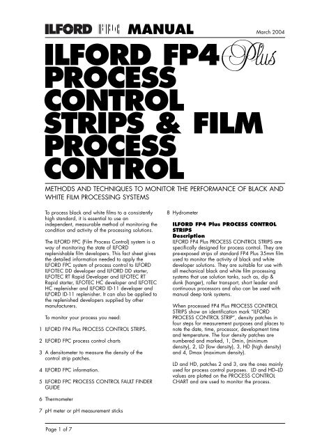
When <strong>process</strong>ed FP4 Plus PROCESS CONTROL<br />
STRIPS show an identification mark “ILFORD<br />
PROCESS CONTROL STRIP”, density patches in<br />
four steps for measurement purposes and places to<br />
note the date, time, <strong>process</strong>or, development time<br />
and temperature. The four density patches are<br />
numbered and marked, 1, Dmin, (minimum<br />
density), 2, LD (low density), 3, HD (high density)<br />
and 4, Dmax (maximum density).<br />
LD and HD, patches 2 and 3, are the ones mainly<br />
used for <strong>process</strong> <strong>control</strong> purposes. LD and HD–LD<br />
values are plotted on the PROCESS CONTROL<br />
CHART and are used to monitor the <strong>process</strong>.<br />
6<br />
7<br />
Thermometer<br />
pH meter or pH measurement sticks<br />
Page 1 of 7
FILM PROCESS CONTROL<br />
Dmin and Dmax, patches 1 and 4, are used for<br />
the diagnosis of problems. The minimum density,<br />
Dmin, is a measurement of the <strong>control</strong> strip’s base<br />
density and fog due to development. Variations in<br />
the minimum density can help to identify trends<br />
when the LD and HD–LD graphs show there is a<br />
problem. Dmax is often too variable to identify<br />
trends and is not plotted for <strong>process</strong> <strong>control</strong><br />
purposes, however it may be helpful to measure<br />
this value when trying to identify <strong>process</strong>ing<br />
problems.<br />
FP4 Plus PROCESS CONTROL STRIPS are supplied<br />
on 30.5m (100ft) lengths of 35mm <strong>film</strong> wound<br />
emulsion inwards (EI). Each strip is approximately<br />
41 cm (16ins) long giving approximately 72<br />
useable <strong>strips</strong> per roll. Notches along the <strong>film</strong>’s<br />
edge and punched holes in the <strong>film</strong> are provided<br />
throughout the roll’s length to enable users to<br />
identify where to cut off single <strong>strips</strong> for use. The<br />
notch and punch holes are approximately 2.5cm<br />
(1in) apart.<br />
ILFORD<br />
PROCESS<br />
CONTROL<br />
STRIP<br />
4 DMAX<br />
3 HD<br />
2 LD<br />
1 DMIN<br />
DATE<br />
TIME<br />
PROCESSOR<br />
DEV/TIME<br />
Handling<br />
Handle and <strong>process</strong> FP4 Plus PROCESS CONTROL<br />
STRIPS in total darkness.<br />
Orientation<br />
If the user always cuts across the <strong>film</strong> between the<br />
punch hole and the notch each strip will have a<br />
notch at its top, (the end with the highest density<br />
patch), and a punch hole at its bottom, (the end<br />
with the lowest density patch). The emulsion side is<br />
towards the user when the notch is at the top right<br />
hand edge and the punch hole is at the bottom<br />
left.<br />
Storage<br />
For short periods of time or while they are being<br />
used, FP4 Plus PROCESS CONTROL STRIPS can<br />
be kept and stored at room temperature, 20ºC<br />
(68ºF), without any significant loss of performance.<br />
For storage long term we recommend that FP4 Plus<br />
PROCESS CONTROL STRIPS are kept refrigerated<br />
at a temperature below 5ºC (41ºF). Storage for<br />
very long time periods should be at temperatures<br />
below -18ºC (0ºF).<br />
Before using the <strong>strips</strong> after refrigeration or<br />
freezing, allow them to reach room temperature<br />
before opening the packaging. The time taken for<br />
this depends on the storage temperature used and<br />
the ambient temperature to be reached. Allow the<br />
warming <strong>process</strong> to occur naturally, do not apply<br />
any form of direct heat to speed this up as it could<br />
damage the <strong>film</strong>.<br />
ILFORD FPC PROCESS CONTROL<br />
CHARTS<br />
Copies of the ILFORD FPC PROCESS CONTROL<br />
CHARTS and instructions for their use can be<br />
downloaded from our web site at<br />
www.<strong>ilford</strong>.com or contact your local ILFORD<br />
selling company or distributor.<br />
ILFORD FPC information<br />
Other ILFORD FPC information including master<br />
copies of user data sheets for recording<br />
information about; development times, solution<br />
preparation, etc. and product fact sheets, can be<br />
obtained from our web site at www.<strong>ilford</strong>.com<br />
or contact your local ILFORD selling company or<br />
distributor.<br />
ILFORD FPC PROCESS CONTROL FAULT<br />
FINDER GUIDE<br />
The ILFORD FPC PROCESS CONTROL FAULT<br />
FINDER GUIDE can be obtained from our web site<br />
at www.<strong>ilford</strong>.com or contact your local<br />
ILFORD selling company or distributor. The<br />
information it contains helps to explain the<br />
meaning of the data on your <strong>process</strong> <strong>control</strong> charts<br />
and is useful when trying to diagnose trends,<br />
problems and their causes.<br />
TEMP<br />
Page 2 of 7
FILM PROCESS CONTROL<br />
SETTING UP YOUR PROCESSES<br />
If you have already installed the solutions in your<br />
<strong>process</strong>or, and it is producing good quality<br />
negatives, go to the section below called ‘Starting<br />
<strong>process</strong> <strong>control</strong>’.<br />
On the other hand, if you are filling a <strong>process</strong>or<br />
with fresh <strong>process</strong>ing solutions make sure you have<br />
the chemicals recommended for your type of<br />
<strong>process</strong>or. You need enough of each chemical to<br />
be able to make up the solutions to fill each of<br />
your machine’s <strong>process</strong> and replenishment tanks.<br />
Refer to the information supplied by your<br />
<strong>process</strong>or’s manufacturer for the quantities of the<br />
working strength solutions required and follow<br />
their recommended procedures for filling the<br />
machine with solutions and preparing it for use.<br />
Make sure your <strong>process</strong>or is calibrated and set to<br />
give the right solution temperatures, agitation,<br />
<strong>process</strong> times and replenishment rates for the<br />
developer and other chemicals you have chosen to<br />
use.<br />
Information about the suitability of a developer or<br />
other chemical for a particular type of <strong>process</strong>ing<br />
machine can usually be obtained from the<br />
chemical supplier. For information about the<br />
suitable application of ILFORD developers and<br />
chemicals please refer to the relevant chemical fact<br />
sheets on our web site at www.<strong>ilford</strong>.com.<br />
Prepare your chosen chemicals in accordance with<br />
the manufacturer’s instructions.<br />
Note: Photographic chemicals are not hazardous<br />
when used correctly. It is recommended that<br />
gloves, eye protection and an apron or overall are<br />
worn when handling and mixing all chemicals.<br />
Always follow the specific health and safety<br />
recommendations on the chemical’s packaging.<br />
If your <strong>film</strong> <strong>process</strong> is producing poor negatives<br />
you should check the following: developer pH and<br />
specific gravity, fixer pH and specific gravity.<br />
Information about the pH and specific gravity<br />
operating values and tolerances of your chemicals<br />
can be obtained from the manufacturer, for<br />
information about ILFORD chemicals consult the<br />
relevant fact sheet. You should also check the<br />
machine’s functions; solution temperatures,<br />
agitation, replenishment rates, <strong>process</strong> times, etc.<br />
and make any necessary adjustments. If the<br />
problems are severe it usually means starting from<br />
fresh.<br />
PROCESSING WITH REPLENISHED<br />
DEVELOPER<br />
The effect of use on a replenished<br />
developer system<br />
Starting from fresh solutions requires some initial<br />
management until the tank of developer becomes<br />
seasoned. The reaction that takes place during <strong>film</strong><br />
development releases by-products (halides) into the<br />
developer, uses up developing agents and<br />
changes the developer’s pH. These combine to<br />
reduce the activity of the developer and without<br />
proper replenishment the developer gradually<br />
ceases to function adequately and eventually<br />
becomes exhausted.<br />
Replenishment has two key functions. It replaces<br />
the active ingredients used during development<br />
and dilutes the by-products that have been formed.<br />
A replenished developer is said to be fully<br />
“seasoned” when the addition of the replenisher<br />
compensates exactly for the new by-products<br />
produced by development. At this point the<br />
concentration of halides and active ingredients<br />
have reached an equilibrium or steady state.<br />
Photochemical material safety data sheets<br />
containing full details for the safe handling,<br />
disposal and transportation of ILFORD chemicals<br />
are available from ILFORD agents or directly from<br />
the ILFORD web site at www.<strong>ilford</strong>.com.<br />
BEFORE STARTING PROCESS CONTROL<br />
Applying <strong>process</strong> <strong>control</strong> to a poor <strong>process</strong> only<br />
maintains poor results so before you can begin to<br />
monitor the state of your <strong>process</strong> it must be<br />
producing good results, i.e. the negatives should<br />
have good density and contrast.<br />
Small changes to the development time or<br />
temperature will correct slightly thin or dense<br />
negatives or ones that are hard or soft in contrast,<br />
but any major problems will need corrections<br />
beyond the scope of this fact sheet. As a guide a<br />
correctly exposed and <strong>process</strong>ed negative of<br />
normal contrast and density should be making a<br />
good print on a mid contrast grade of paper,<br />
grades 2 or 3.<br />
Page 3 of 7
FILM PROCESS CONTROL<br />
It is maintaining this equilibrium that gives a<br />
machine developer performance consistency.<br />
Provided that the developer is used regularly,<br />
replenishment continues and all other factors<br />
remain the same, i.e. the concentration of the<br />
active ingredients, the by-products, etc. then the<br />
developer should perform consistently for a long<br />
period of time.<br />
Fresh versus seasoned developer and<br />
the function of starter and replenisher<br />
solutions<br />
There are two types of replenished developer<br />
systems. One consists of a solution that acts as<br />
both the developer and the replenisher solution<br />
and has a separate “starter” solution additive that<br />
turns replenisher into developer. The other consists<br />
of a developer solution and a separate replenisher<br />
solution.<br />
ILFORD ILFOTEC DD and ILFORD ILFOTEC RT<br />
Rapid developers are examples of<br />
developer/replenisher plus starter systems,<br />
whereas ILFORD ILFOTEC HC and ILFORD ID-11<br />
are examples of developer plus replenisher<br />
systems.<br />
A tank of freshly made working strength developer<br />
is usually more active than a tank of “seasoned”<br />
replenished developer. If the same <strong>process</strong> time is<br />
used in both cases then a small loss in <strong>film</strong> speed<br />
and contrast will be seen using the seasoned<br />
developer. The change in performance from fresh<br />
to seasoned is gradual with each <strong>film</strong> <strong>process</strong>ed<br />
until the equilibrium point is reached.<br />
In a developer/replenisher <strong>process</strong> system a starter<br />
solution is used to minimise the performance<br />
difference between fresh and seasoned solutions.<br />
In a replenished <strong>process</strong> system with separate<br />
developer and replenisher solutions, the<br />
replenisher is formulated to be more active than<br />
the developer. The addition of this more active<br />
solution minimises the performance differences<br />
between the fresh and seasoned condition.<br />
The time taken to reach equilibrium from fresh<br />
depends on a number of factors; the developer<br />
and replenisher formulae, tank size, the amount of<br />
<strong>film</strong> <strong>process</strong>ed and their type and the<br />
replenishment rates used. Information specific to<br />
the ILFORD developers, ILFOTEC DD, ILFOTEC RT<br />
Rapid, ILFOTEC HC and ID-11 can be found in the<br />
relevant product fact sheets.<br />
1<br />
2<br />
3<br />
STARTING PROCESS CONTROL USING<br />
FP4 Plus PROCESS CONTROL STRIPS<br />
Preparing master <strong>strips</strong> and aim<br />
values<br />
If your developer is giving you the quality of<br />
negative that you require then to start a <strong>process</strong><br />
<strong>control</strong> system you need to:<br />
Produce master <strong>process</strong> <strong>control</strong> <strong>strips</strong>.<br />
Calculate the aim values from these master <strong>strips</strong> to<br />
create a benchmark for your <strong>process</strong>.<br />
Start a <strong>process</strong> <strong>control</strong> chart with these aim values.<br />
To produce your master <strong>strips</strong>, first <strong>process</strong> three<br />
FP4 Plus PROCESS CONTROL STRIPS. Process<br />
these <strong>strips</strong> when the developer is producing<br />
satisfactory results, but not immediately after a<br />
period of inactivity, for example, a weekend.<br />
The table below gives development times for FILM<br />
PROCESS CONTROL STRIPS in ILFORD developers<br />
at their recommended working temperatures. These<br />
development times will need some adjustment if<br />
you are operating your <strong>process</strong>or at either higher<br />
or lower temperature than the one shown. Process<br />
the FP4 Plus PROCESS CONTROL STRIPS at the<br />
time you use for FP4 Plus<br />
Recommended development times in ILFORD<br />
replenished developers<br />
Developer Dilution Temperature Time<br />
ºC/ºF min:sec<br />
ILFOTEC DD 1+4 24/75 8:30<br />
ILFOTEC RT RAPID 1+1+2 26/78 0:45<br />
ILFOTEC RT RAPID 1+1+5 26/78 0:65<br />
ILFOTEC HC 1+15 22/72 4:00<br />
ILFOTEC HC 1+31 22/72 8:00<br />
ID–11 Stock 20/68 8:30<br />
Fill in the first part of a new ILFORD PROCESS<br />
CONTROL CHART with the <strong>process</strong> details<br />
including development time, temperature, the date,<br />
etc.<br />
After <strong>process</strong>ing any <strong>strips</strong> measure the density of<br />
the patches using a calibrated transmission<br />
densitometer and record the results for Dmin, LD<br />
and HD. Examine the <strong>strips</strong>, a visual assessment of<br />
density cannot be relied upon for the purposes of<br />
<strong>process</strong> <strong>control</strong> but the <strong>strips</strong> should be checked for<br />
any anomalies such as dirt, debris or drying<br />
defects as this may indicate other problems.<br />
Next tabulate the density values of the LD and HD<br />
patches of all three master <strong>strips</strong> and calculate the<br />
HD-LD values.<br />
Page 4 of 7
FILM PROCESS CONTROL<br />
Example<br />
LD HD HD–LD<br />
(patch 2) (patch 3)<br />
Strips 1 0.47 1.28 0.81<br />
Strip 2 0.49 1.29 0.80<br />
Strip 3 0.48 1.27 0.79<br />
Calculate the average LD value by adding the<br />
three LD figures together and dividing the result by<br />
three, = 0.48 in this example. Calculate the<br />
average HD–LD value using the same method,<br />
= 0.80 in this example. Round the result of these<br />
calculations to two decimal places, if necessary.<br />
Enter the average LD and HD–LD values into the<br />
LD and HD – LD aim value boxes on the ILFORD<br />
<strong>process</strong> <strong>control</strong> chart (see the example chart in the<br />
“Introduction to the FPC Process Control Manual”<br />
fact sheet). In the above example this would be LD<br />
= 0.48 and HD – LD = 0.80<br />
Typical aim values for FP4 Plus CONTROL STRIPS<br />
in ILFORD developers are shown in the table<br />
below. These are supplied as indicators of the<br />
values that can be expected from a typical<br />
<strong>process</strong>. You should not attempt to adjust your<br />
<strong>process</strong> to obtain identical values to the ones<br />
given below. It is far more important that you are<br />
satisfied with the quality of the negatives you are<br />
producing and record the <strong>control</strong> values that this<br />
gives you to use as your aim.<br />
Typical aim values<br />
Developer Dilution Dmin LD HD–LD<br />
ILFOTEC DD 1+4 0.35 0.51 0.80<br />
ILFOTEC RT RAPID 1+1+2 0.35 0.54 0.80<br />
ILFOTEC RT RAPID 1+1+5 0.35 0.41 0.80<br />
ILFOTEC HC 1+15 0.30 0.45 0.80<br />
ILFOTEC HC 1+31 0.30 0.45 0.80<br />
ID–11 Stock 0.35 0.45 0.80<br />
Plotting <strong>process</strong> <strong>control</strong> values and<br />
tolerances<br />
FP4 Plus CONTROL STRIPS should be regularly<br />
<strong>process</strong>ed at the development time you usually use<br />
for FP4 Plus <strong>film</strong>. The frequency of <strong>process</strong>ing<br />
<strong>control</strong> <strong>strips</strong> is for the user to decide based on<br />
your workload and work patterns. You may only<br />
need to do it daily or you may want to do it at the<br />
beginning, middle and end of each working<br />
session. We suggest that at least one <strong>control</strong> strip<br />
is <strong>process</strong>ed per working session and it is best to<br />
do this and assess it before any other <strong>film</strong> is<br />
<strong>process</strong>ed. However, in a busy working<br />
environment this may not always be practical.<br />
After <strong>process</strong>ing the strip, measure the density of<br />
the patches using a calibrated transmission<br />
densitometer and record the results for Dmin, LD<br />
and HD-LD on the <strong>process</strong> <strong>control</strong> chart you have<br />
started. Remember a visual assessment of density<br />
cannot be relied upon for <strong>process</strong> <strong>control</strong> to<br />
operate.<br />
1<br />
2<br />
3<br />
4<br />
5<br />
6<br />
The steps involved in the day–to–day monitoring of<br />
your <strong>process</strong> using the ILFORD <strong>process</strong> <strong>control</strong><br />
system are:<br />
Prepare the <strong>process</strong>or for work.<br />
Check the <strong>process</strong>or’s functions are working and<br />
set correctly, e.g. solution temperatures, agitation<br />
systems, speed <strong>control</strong>s, replenishment solutions<br />
and rates, etc.<br />
Process a <strong>control</strong> strip.<br />
Visually assess this <strong>control</strong> strip.<br />
Measure the <strong>control</strong> strip densities.<br />
Calculate the HD – LD value<br />
Plot the <strong>control</strong> <strong>strips</strong> LD and HD - LD values on the<br />
<strong>control</strong> chart you have started.<br />
Instructions for preparing your <strong>process</strong>or for work<br />
should be covered by the manual for the particular<br />
machine you are using. You may need to top up<br />
the <strong>process</strong> tanks with water to compensate for<br />
any overnight evaporation from the solutions.<br />
Allow the <strong>process</strong>or to get up to its working<br />
temperature.<br />
When the <strong>process</strong>or is ready for work, <strong>process</strong> a<br />
<strong>control</strong> strip, using the same settings and<br />
temperature as for the master <strong>strips</strong>. Examine this<br />
strip visually for streaks, spots, drying marks etc.<br />
then measure the density of the Dmin, LD and HD<br />
patches, and calculate the HD–LD value. Enter the<br />
Dmin value in the Dmin box in the next free<br />
column of the <strong>control</strong> chart. Then, for the LD and<br />
HD–LD figures, subtract the aim values from each<br />
of the newly measured values to obtain the plot<br />
values from the aim as shown below.<br />
Example<br />
LD HD–LD<br />
New strip 0.49 0.79<br />
Aim values 0.48 0.80<br />
Plot values +0.01 -0.01<br />
Plot the results on the <strong>control</strong> chart in the same<br />
column as the Dmin value, adding the date, time<br />
and any comments at the top. The <strong>process</strong> is<br />
considered in <strong>control</strong> provided that the<br />
measurements from subsequent <strong>strips</strong> are within<br />
±0.06 units of the established aim values, i.e. the<br />
plot stays within the boundaries of the upper and<br />
lower ”ACTION” lines marked on the PROCESS<br />
CONTOL CHART.<br />
Page 5 of 7
FILM PROCESS CONTROL<br />
Regularly recording other pieces of information on<br />
the chart is also very useful as it can help to<br />
diagnose any problems that occur e.g. keeping a<br />
tally of the <strong>film</strong>s <strong>process</strong>ed during the day and<br />
adding the total to the chart is a very useful piece<br />
of information as is adding the results of any pH<br />
and specific gravity measurements and any<br />
changes in solution temperature you have made.<br />
Making new master <strong>strips</strong> and<br />
adjusting aim values<br />
New master <strong>strips</strong> are needed when the chemicals<br />
are replaced and when a major adjustment has<br />
been made to the developer. For example, if part<br />
of the developer tank solution has been drained<br />
and refreshed with new developer solution or if<br />
the working temperature is changed significantly. It<br />
is advisable to start a new PROCESS CONTROL<br />
CHART when you make new master <strong>strips</strong>.<br />
Before making new master <strong>strips</strong>, the <strong>process</strong>or<br />
must be producing good results, but do not make<br />
new master <strong>strips</strong> immediately after a period of<br />
inactivity, for example, a weekend. To prepare<br />
new master <strong>strips</strong> repeat the procedure given the<br />
section above called “Preparing master <strong>strips</strong> and<br />
aim values”.<br />
New master <strong>strips</strong> and aim values can be made<br />
when changing to a new box of FP4 Plus<br />
CONTROL STRIPS as there might be slight<br />
variations between boxes of <strong>strips</strong> due, for<br />
example, to different ages or storage conditions or<br />
slight changes in exposure. However, it is more<br />
convenient to just adjust the existing aim values for<br />
the performance of the new <strong>strips</strong>. To do this<br />
<strong>process</strong> the last strip in the old pack at the same<br />
time as the first strip of the new pack. If the old<br />
and the new <strong>strips</strong> give the same readings<br />
continue as normal.<br />
If the two <strong>strips</strong> give different readings, adjust the<br />
aim values for LD and HD–LD, and start a new<br />
<strong>process</strong> <strong>control</strong> chart. Adjust the aim values by<br />
subtracting the value on the old strip from the<br />
value on the new strip and adding the result to the<br />
aim value.<br />
Example<br />
Assume the LD aim value is 0.48. If the LD value<br />
of the last strip in the pack is 0.50 and the LD<br />
value of the first strip of the new pack is 0.49,<br />
then add -0.01 to the LD aim value, making it<br />
0.47.<br />
DEALING WITH PROCESS VARIATIONS<br />
Identifying <strong>process</strong> variations<br />
A properly replenished and maintained developer<br />
in regular use should have a long tank life. Any<br />
large <strong>process</strong> variations seen are most likely to be<br />
caused by an external change. If a sudden and<br />
significant <strong>process</strong> variation has occurred it is most<br />
important to identify the cause so that the<br />
appropriate corrective action can be taken.<br />
For the life of the developer both the LD and<br />
HD–LD plots should remain between the two<br />
“ACTION” limit lines that are marked on the<br />
PROCESS CONTROL CHART. Movement between<br />
these lines should be minimal but if they do occur<br />
they should be gradual undulating trends rather<br />
than sharp swings from one extreme to another.<br />
However, random variations are bound to occur<br />
occasionally, so when you plot a point that lies<br />
outside the limits, immediately <strong>process</strong> and plot<br />
another strip to check the first result. If the plotted<br />
points from the second strip are inside the action<br />
limits continue to use the developer as normal. If<br />
the results from the second strip are outside the<br />
same limit, action is needed.<br />
It should still be possible for you to continue<br />
<strong>process</strong>ing so long as the results remain inside the<br />
“CONTROL” limit line that is marked on the<br />
PROCESS CONTROL CHART. However, it is<br />
advisable to <strong>process</strong> a test <strong>film</strong> to assess the<br />
acceptability of the negatives produced before<br />
continuing.<br />
If a point is plotted outside one of the “CONTOL”<br />
limits, and the results from a second strip are also<br />
outside the same limit, you should not <strong>process</strong> any<br />
further <strong>film</strong>s until the source of the variation has<br />
been corrected.<br />
Identifying a problem<br />
The most important part of dealing with <strong>process</strong><br />
variation is identifying what has caused it.<br />
Replenished developer systems, should have a<br />
very long tank life as the developer in the tank is<br />
being replaced as it used, so any <strong>process</strong><br />
variation is most likely to be caused by an external<br />
change. If you do not find the cause of a problem<br />
you cannot prevent it from recurring.<br />
Firstly, look for the obvious. The cause of the<br />
<strong>process</strong> change may be something visible, such as<br />
low solution level or blocked pipes. Put a test <strong>film</strong><br />
through the machine and check that it correctly<br />
triggers any agitation, replenishment etc. Also<br />
check for any obvious source of contamination,<br />
e.g. something floating in the developer,<br />
cloudiness or an unusual odour.<br />
Next check all of the machine settings. Somebody<br />
may have changed the temperature, development<br />
time or replenishment rate for a particular job, or<br />
merely by accident. If possible, verify the settings<br />
by measuring what has actually been set using<br />
thermometers, measuring cylinders etc.<br />
Page 6 of 7
FILM PROCESS CONTROL<br />
Regaining <strong>control</strong> of the <strong>process</strong><br />
Once the cause of the problem has been found<br />
and corrected then some action will probably be<br />
needed to get the <strong>process</strong> back within limits. It<br />
might happen automatically, for example if the<br />
temperature has been returned to the correct<br />
setting. If the problem was caused by low<br />
replenishment then removing a few litres of<br />
developer and replacing it with an equal amount<br />
of fresh developer or replenisher solution may<br />
bring the <strong>process</strong> back in <strong>control</strong>. In the extreme<br />
case to get back inside the limits may need all of<br />
the developer solution replacing with fresh<br />
developer.<br />
If the reason for poor performance is<br />
contamination of the developer by stop bath or<br />
fixer then remove all the developer, flush out<br />
pumps and pipes, clean the tank and change the<br />
solution filter before replacing with a fresh<br />
solution.<br />
A guide to the severity of the problem can be<br />
gained by studying the shape of the plot on the<br />
PROCESS CONTROL CHART. There are basically<br />
two types of change, gradual and sudden. A<br />
gradual change shows as a trend in one or more<br />
of the <strong>control</strong> plots stretching over days or possibly<br />
weeks. This normally indicates a small change in<br />
<strong>process</strong>ing conditions, which is more likely to be<br />
cured by replacing a relatively small amount of<br />
developer or a small adjustment to replenishment<br />
rates.<br />
A plot that shows a sudden change from a stable<br />
situation to out of <strong>control</strong> in one jump is likely to<br />
be caused by a major contamination. This is likely<br />
to require a complete change of developer, and<br />
possibly flushing of the machine as well, to<br />
remove the problem.<br />
You should note that neither of these categories is<br />
absolutely exclusive. If in doubt, err on the side of<br />
safety and replace the developer.<br />
For more information about what the PROCESS<br />
CONTROL CHART plots are telling you and<br />
dealing with common causes of <strong>process</strong> variation<br />
read the ILFORD FPC PROCESS CONTROL FAULT<br />
FINDER GUIDE.<br />
A wide range of fact sheets is available which describe and<br />
give guidance on using ILFORD products. Some products in<br />
this fact sheet might not be available in your country.<br />
ILFORD Imaging UK Limited, Town Lane, Mobberley,<br />
Knutsford, Cheshire WA16 7JL, England<br />
www.<strong>ilford</strong>.com<br />
Page 7 of 7<br />
03211.4.GB.www March 2004