HP COMBI PLAN âTâ
HP COMBI PLAN âTâ
HP COMBI PLAN âTâ
Create successful ePaper yourself
Turn your PDF publications into a flip-book with our unique Google optimized e-Paper software.
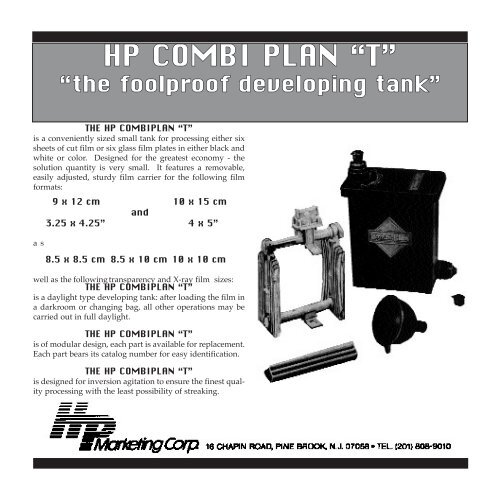
<strong>HP</strong> <strong>COMBI</strong> <strong>PLAN</strong> “T”<br />
“the foolproof developing tank”<br />
THE <strong>HP</strong> <strong>COMBI</strong><strong>PLAN</strong> “T”<br />
is a conveniently sized small tank for processing either six<br />
sheets of cut film or six glass film plates in either black and<br />
white or color. Designed for the greatest economy - the<br />
solution quantity is very small. It features a removable,<br />
easily adjusted, sturdy film carrier for the following film<br />
formats:<br />
a s<br />
9 x 12 cm<br />
3.25 x 4.25”<br />
and<br />
10 x 15 cm<br />
4 x 5”<br />
8.5 x 8.5 cm 8.5 x 10 cm 10 x 10 cm<br />
well as the following transparency and X-ray film sizes:<br />
THE <strong>HP</strong> <strong>COMBI</strong><strong>PLAN</strong> “T”<br />
is a daylight type developing tank: after loading the film in<br />
a darkroom or changing bag, all other operations may be<br />
carried out in full daylight.<br />
THE <strong>HP</strong> <strong>COMBI</strong><strong>PLAN</strong> “T”<br />
is of modular design, each part is available for replacement.<br />
Each part bears its catalog number for easy identification.<br />
THE <strong>HP</strong> <strong>COMBI</strong><strong>PLAN</strong> “T”<br />
is designed for inversion agitation to ensure the finest quality<br />
processing with the least possibility of streaking.
DESCRIPTION OF THE <strong>HP</strong> <strong>COMBI</strong><strong>PLAN</strong> “T”<br />
The <strong>HP</strong> <strong>COMBI</strong> <strong>PLAN</strong> “T” is manufactured from the<br />
highest quality plastic which, even after prolonged use, is<br />
highly resistant to corrosion from all known photographic<br />
chemicals, especially the current color developers. In<br />
addition, the plastic is an efficient insulator which helps to<br />
maintain a consistent temperture during processing.<br />
The <strong>HP</strong> <strong>COMBI</strong> <strong>PLAN</strong> “T” consists of the following<br />
parts:<br />
1. Lid No. 459409<br />
made from an extra strong, flexible plastic material. This<br />
ensures that the lid fits securely on the 459407 tank body<br />
and makes inversion agitation possible – the best developing<br />
method known. The opening in the lid for filling and<br />
draining is provided with a ventilation slot and can be fitted<br />
with a light-tight screw-in nipple 459421, which accepts<br />
the funnel 459425 or the leak proof cap 459422.<br />
459409<br />
3. Negative Carrier 459812<br />
for up to 6 sheet films or glass plates. The negative carrier<br />
consists of the following parts:<br />
A. Two grooved side plates 459412<br />
of clear plastic. On one side the grooves are straight for<br />
use with glass plates, the other side is curved for use with<br />
sheet films.<br />
B. Upper spacer rod 459413<br />
with format markings and handle. The holes in the handle<br />
allow the negative carrier to be easily hung for drying.<br />
C. Lower spacer rod 459414<br />
with raised film separators on the bottom plate.<br />
D. Two locking rings 459415<br />
to fasten the upper and lower spacer rods to the grooved<br />
side plates.<br />
E. Film loading guide 459416<br />
to facilitate the loading of sheet film into the negative carrier<br />
in the dark. Not used with glass plates.<br />
F. Slip-on ratcheting film retaining clip 459417<br />
slips on to the handle of the negative carrier to hold the<br />
film in place, properly separated, and keeps film from slipping<br />
out of the carrier during inversion agitation.<br />
IMPORTANT: PLEASE SEE LAST PAGE FOR DETAILS<br />
459407<br />
459417<br />
459413<br />
459420<br />
2. Tank Body 459407<br />
(Daylight Type) accommodates film carrier 459812.<br />
Its well designed shape enables the user to easily and<br />
firmly grip the tank with one hand. The raised, vertical<br />
grooves in the front and back of the tank help to prevent<br />
slipping – even with wet hands! An outlet is provided on<br />
the bottom of one of the small sides to accept either the<br />
light tight screw-in hose connector 459421 or the<br />
screw-in stopper 459418.<br />
459412<br />
459416<br />
459412<br />
459415<br />
4. Two light-tight screw-in hose connectors<br />
459421 one each for the lid and the tank body openings.<br />
5. Two stopper caps 459422
6. Funnel 459425<br />
fits in to the light-tight hose connector on lid for filling the<br />
tank with chemistry or water.<br />
459418<br />
459425<br />
459419<br />
HOW TO USE THE <strong>HP</strong> <strong>COMBI</strong><strong>PLAN</strong> “T” TANK<br />
A. Assembly of the negative carrier.<br />
It’s important that the negative carrier is properly assembled<br />
for the type of material that is used. For sheet films<br />
the curved sides of the film retaining plates must face each<br />
other and the straight grooves must be on the outside of<br />
the film retaining plate. When developing glass plates the<br />
film retaining plates are reversed with the straight grooves<br />
facing each other (Ill A). Curved grooves are used for sheet<br />
films for greater strength so they can resist the pressure of<br />
the solutions during inverse agitation. The two spacer<br />
rods, 459413, 459414, have a bayonet lock to adjust for<br />
various film formats and a thread on the opposite end that<br />
accepts the locking screw rings 459415. The bayonet cutouts<br />
are numbered to indicate the format positions.<br />
459421<br />
459422<br />
1 2<br />
3 4<br />
<strong>HP</strong> <strong>COMBI</strong><strong>PLAN</strong> “T” ACCESSORY:<br />
1. Screw-in stopper 459418<br />
with rubber washer – used instead of the light-tight screwin<br />
hose connector 459421.<br />
To assemble the negative carrier the upper rod is inserted<br />
into the upper opening of the grooved plate with its groove<br />
down so that the notch in the opening fits smoothly into the<br />
groove. As soon as the figure indicating the correct format<br />
is over the notch and the latter is in the groove, turn the rod<br />
clockwise until it stops (Illus. 3). The lower rod is similarly<br />
inserted, the only difference is that the notch and groove<br />
should face up. The second grooved plate is now slipped<br />
over the rod’s screw thread. The notches in the openings<br />
of the plates rest on the flat portion of the screws, preventing<br />
any accidental turning of the rods. Assemble the negative<br />
carrier securely by tightening the screw rings 459415<br />
firmly onto the threaded ends of the rods (Illus. 1).
When using larger film sizes even greater stability of the<br />
negative carrier is obtained by inserting the connecting rods<br />
into the plates in such a way that one screw thread will be<br />
on the left and the other on the right side of the negative<br />
carrier (Illus. 2).<br />
The following table indicates the figures to be used on the<br />
spacer rods for various film formats:<br />
1 2 3 4<br />
10 x 15 cm 9 x 12 cm --<br />
10 x 10 cm -- -- --<br />
4 x 5” 3.5 x 4.75” 3.25 x 4.25” 2.5 x 3.5”<br />
B. Inserting sheet film or glass plates in the dark<br />
To load sheet films in the carrier it is easiest to use loading<br />
guide 459416. The two upper cross bars of the frame have<br />
sharp edges while the lower one is rounded. This eases<br />
identifying the slots in the dark and lessens the danger of<br />
accidentally putting two films into one slot. It also prevents<br />
inserting film at an angle (Illus. 6).<br />
PLATES FILM FILM<br />
When loading it is preferable to insert the first film or plate<br />
into the slot closest to the handle. When using the film<br />
guide frame insert the first film into the top slot in the frame,<br />
the second sheet into the middle slot and the last sheet into<br />
the bottom slot. The film must rest firmly on the film stop<br />
plate of the lower spacer rod. Films should be inserted so<br />
the emulsion side faces forward and the backing faces the<br />
center of the carrier. This ensures that the emulsion will be<br />
pressed away from the grooves when the film retaining clip<br />
is positioned thus allowing the chemistry to reach all areas<br />
of the emulsion including the extreme edges.<br />
When processing very valuable films it is advisable to insert<br />
only two films on each side of the carrier with no film in the<br />
center slots.<br />
To remove the loading frame slightly raise the bottom edge<br />
of the frame and then lift it off.<br />
When the loading frame guide has been removed slip the<br />
film retaining clip over the handle on the upper spacer rod<br />
and slide it down until it contacts the upper edge of the<br />
film. Make sure that the upper edges of the film are properly<br />
separated and that the clip holds its position firmly.<br />
Also check that the bottom edges of the film are properly<br />
separated on the lower spacer rod’s stop plate (Illus. 8).<br />
IMPORTANT: SEE LAST PAGE FOR ADDED INSTRUCTIONS.<br />
Illus. 5 Illus. 6 Illus. 7<br />
The loading of glass plates is made easier by the protruding<br />
upper tips of the grooves which serve as loading guides<br />
(Illus. 5).<br />
The loading guide frame is hooked into position by placing<br />
the top cross bar over the two projecting guide grooves and<br />
then pressing the bottom edge of the loading frame into<br />
the cut-out on the sides of the carrier plates (Illus. 7). This<br />
prevents the guide frame from slipping while working in<br />
the dark.<br />
Illus. 8<br />
Now place the loaded<br />
carrier into the tank and press the lid firmly over the edge<br />
of the tank until it makes firm contact with the rim. Screw<br />
the light-tight hose connectors (459421) into the openings<br />
on the lid and in the tank body.<br />
To remove the lid simply lift up on one corner.<br />
D. Processing with a line of Combi Plan tanks.
C. Developing with the <strong>HP</strong> Combiplan “T”<br />
Loading the negative carrier with film or plates must be<br />
done in total darkness. All processing operations may be<br />
performed in daylight once the tank is closed.<br />
If the first solution has not been poured into the tank before<br />
insertion of the negative carrier proceed as follows:<br />
a. TO FILL THE <strong>COMBI</strong> <strong>PLAN</strong> “T”<br />
1. Put funnel 459425 on connector 459421 on the lid.<br />
2. Turn nipple 1/2 turn counter-clockwise to open air<br />
path.<br />
3. Close the nipple on the tank body with cap 459422.<br />
4. Measure the required amount of solution as per the<br />
table below and pour into the tank through the funnel.<br />
A shield positioned under the opening in the lid prevents<br />
the solutions from splashing on the film while the tank is<br />
filling. The shield ensures that the solutions will rise evenly<br />
from the bottom of the tank which results in even development.<br />
9 x 12cm 3.25 x 4.25” 4 x 5”<br />
1000 ccm 1000 ccm 1050 ccm<br />
35 oz 35 oz 36 oz<br />
b. PROCESSING METHOD<br />
1. Remove the funnel and cap the screw-in nipple.<br />
2. Close the air path by firmly turning the screw-in<br />
nipple clockwise.<br />
3. Firmly tap the closed tank several times on a hard<br />
surface to dislodge any air bubbles from the film’s surface.<br />
abrupt tilting of the tank from side to side, and alternately<br />
to the left and right in an arc of approx. 180°. Please follow<br />
film manufacturers directions for frequency and length of<br />
agitation.<br />
c. DRAINING THE <strong>COMBI</strong> <strong>PLAN</strong> “T”<br />
1. Remove the cap from the screw-in nipple on the lid.<br />
2. Put funnel into the solution bottle.<br />
3. Remove cap from the screw-in nipple on the tank’s<br />
side and pour solution through the funnel into the bottle.<br />
Illus. 10<br />
4. Washing is easily accomplished<br />
as per illustration 10. A rubber hose runs from the<br />
faucet to the screw-in nipple on the side of the tank. The<br />
pressure of the water forced through the tank from the bottom<br />
to the top ensures a particularly through washing.<br />
It is advisable to periodically reverse the negative carrier<br />
during the wash cycle to prevent any possible damage to<br />
the film during the wash.<br />
d. CLEANING THE TANK AND THE NEGATIVE CARRIER<br />
After each developing session the negative carrier should<br />
be disassembled and each part cleaned with a brush in<br />
luke-warm water to which a little detergent is added. The<br />
same procedure should be used to clean the tank and the<br />
lid. NEVER USE HOT OR BOILING WATER. NEVER<br />
PLACE THE PARTS ON A STOVE, HOT PLATE OR NEAR<br />
A FIRE FOR DRYING. It is important to note that film can<br />
easily and safely be loaded into a damp negative carrier<br />
when processing several loads of film.<br />
Illus. 9<br />
4. Inverse agitate the solutions by a smooth, not too
If there is a large amount of processing to be done it may be<br />
advisable to assemble a processing line. This can be easily<br />
and economically accomplished as shown below. Note that<br />
the number of tanks required will depend on the process<br />
used.<br />
Please be sure to cover any open tanks to prevent oxidation.<br />
A piece of plastic food wrap laid over the open top<br />
of a tank is an inexpensive and effective way of preventing<br />
oxidation.<br />
GENTLY PRESS THESE TWO BARS<br />
DO NOT PRESS ARMS<br />
E. Proper use and care of Film Retaining Clip 459417.<br />
Four small ratchets on the clip engage four rack type bars<br />
on the outer edges of the handle on the upper spacer bar to<br />
securely lock the film retaining clip onto the handle.<br />
TO DISENGAGE AND REMOVE THE CLIP FROM THE HANDLE<br />
GENTLY PRESS TOGETHER THE 2 BARS OF THE CLIP (ILLUS. 11)<br />
USING THE THUMB AND INDEX FINGERS OF BOTH HANDS AND LIFT<br />
OFF. (ILLUS. 13 FRONTAL VIEW)<br />
THE INHERENT SPRING ACTION OF THE PLASTIC MATERIAL USED<br />
FULLY MEETS THESE REQUIREMENTS. DO NOT ABUSE THE CLIP.<br />
NEVER SQUEEZE OR PULL APART THE CLIP BY FORCE. (ILLUS. 12)<br />
AVOID EXCESSIVE WEAR BY NEVER ALLOWING THE RATCHETS OF<br />
THE CLIP TO RIDE AGAINST THE RACKS OF THE HANDLE. ALWAYS<br />
SLIP-ON OR REMOVE THE CLIP WITH THE RATCHETS RELEASED, IE.<br />
WITH A GENTLE BUT FIRM PRESSURE ON THE 2 BARS OF THE CLIP<br />
(ILLUS. 14).<br />
Illus. 11 Illus. 12<br />
SQUEEZE BARS AND LIFT<br />
Illus. 13 Illus. 14<br />
THE PROFESSIONAL PROCESSING SYSTEM<br />
THAT IS BEST SUITED TO YOUR NEEDS.<br />
MADE IN SWEDEN<br />
<strong>HP</strong> <strong>COMBI</strong> <strong>PLAN</strong> “T”<br />
“the foolproof developing tank”


