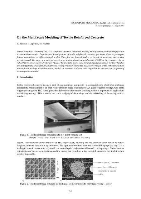
On the Multi Scale Modeling of Textile Reinforced Concrete
On the Multi Scale Modeling of Textile Reinforced Concrete
On the Multi Scale Modeling of Textile Reinforced Concrete

You also want an ePaper? Increase the reach of your titles
YUMPU automatically turns print PDFs into web optimized ePapers that Google loves.
TECHNISCHE MECHANIK, Band 28, Heft 1, (2008), 53 – 63<br />
Manuskripteingang: 31. August 2007<br />
<strong>On</strong> <strong>the</strong> <strong>Multi</strong> <strong>Scale</strong> <strong>Modeling</strong> <strong>of</strong> <strong>Textile</strong> <strong>Reinforced</strong> <strong>Concrete</strong><br />
B. Zastrau, I. Lepenies, M. Richter<br />
<strong>Textile</strong> reinforced concrete (TRC) is a composite <strong>of</strong> textile structures made <strong>of</strong> multi-filament yarns (rovings) within<br />
a cementitious matrix. Experimental investigations <strong>of</strong> textile reinforced concrete specimens show very complex<br />
failure mechanisms on different length scales. Therefore mechanical models on <strong>the</strong> micro, meso and macro scale<br />
are introduced. The paper presents an overview on a hierarchical material model <strong>of</strong> TRC on three scales – <strong>the</strong> so<br />
called Micro-Meso-Macro-Prediction-Model. While on <strong>the</strong> micro scale <strong>the</strong> individual filaments <strong>of</strong> <strong>the</strong> fiber bundles<br />
are distinguished to determine an effective roving behavior within <strong>the</strong> mesoscopic model <strong>of</strong> <strong>the</strong> cementitious bulk<br />
material with rovings as reinforcement, models on <strong>the</strong> meso scale are used to predict <strong>the</strong> macroscopic response <strong>of</strong><br />
<strong>the</strong> composite material.<br />
1 Introduction<br />
<strong>Textile</strong> reinforced concrete is a new kind <strong>of</strong> a cementitious composite. In contradiction to short fiber reinforced<br />
concrete <strong>the</strong> reinforcement is an open textile structure made <strong>of</strong> continuous AR-glass or carbon rovings. <strong>On</strong>e <strong>of</strong> <strong>the</strong><br />
biggest advantages <strong>of</strong> TRC is <strong>the</strong> quasi-ductile behavior after matrix cracking, which is important for applications<br />
in civil engineering. This is due to <strong>the</strong> crack bridging <strong>of</strong> <strong>the</strong> rovings and <strong>the</strong> debonding <strong>of</strong> <strong>the</strong> roving-matrixinterface.<br />
Figure 1. <strong>Textile</strong> reinforced concrete plate in 4-point-bending test<br />
(length l = 600 mm, width w = 300 mm, thickness t = 8 mm)<br />
Figure 1 illustrates <strong>the</strong> ductile behavior <strong>of</strong> TRC impressively, knowing that <strong>the</strong> behavior <strong>of</strong> <strong>the</strong> matrix as well as<br />
<strong>the</strong> glass yarns are very brittle by <strong>the</strong>re own. The open reinforcement structure – so called lay-ups (cp. fig. 2) – is<br />
leading to a crack pattern with very small crack openings in conjunction with small crack spacings. Fur<strong>the</strong>rmore an<br />
optimization <strong>of</strong> <strong>the</strong> roving orientation and <strong>the</strong> roving size regarding to <strong>the</strong> expected stresses in <strong>the</strong> final structural<br />
member is possible.<br />
appr. 1cm<br />
0.25 mm<br />
sleeve (outer) filaments<br />
core (inner) filaments<br />
cementitious matrix<br />
voids<br />
a)<br />
b)<br />
Figure 2. <strong>Textile</strong> reinforced concrete: a) multiaxial textile structure b) embedded roving (155 tex)<br />
53
The behavior <strong>of</strong> TRC is characterized by complex damage and failure mechanisms on different material length<br />
scales. Beside <strong>the</strong> delamination <strong>of</strong> whole plies macroscopic matrix cracking occurs due to tension. Moreover <strong>the</strong><br />
individual filaments <strong>of</strong> a roving can fail. Therefore a hierarchical material model is introduced [Lepenies et al.<br />
(2003); Lepenies (2007)], cp. fig. 3.<br />
2 <strong>Multi</strong> <strong>Scale</strong> Analyses<br />
<strong>Multi</strong> scale analyses (MSA) can be classified in two kinds <strong>of</strong> approaches, <strong>the</strong> hierarchical and <strong>the</strong> simultaneous<br />
MSA. Within a hierarchical MSA <strong>the</strong> model parameters <strong>of</strong> <strong>the</strong> macroscale are determined by means <strong>of</strong> homogenization<br />
associated with micromechanical field variables. Here a scale transition takes place. After <strong>the</strong> determination<br />
<strong>of</strong> effective elastic properties <strong>of</strong> <strong>the</strong> composite material no more microscopic analyses are necessary for <strong>the</strong><br />
application <strong>of</strong> <strong>the</strong> macroscopic model.<br />
<strong>On</strong> <strong>the</strong> o<strong>the</strong>r hand <strong>the</strong> simultaneous MSA – also called concurrent or integrated MSA – solves <strong>the</strong> models on all<br />
scales at <strong>the</strong> same time. Therefore <strong>the</strong> macroscopic model is affected by <strong>the</strong> response <strong>of</strong> <strong>the</strong> microscopic model<br />
and vice versa. This occurs, if a macroscopic stress redistribution takes place due to <strong>the</strong> non-linear behavior <strong>of</strong> <strong>the</strong><br />
micro models. Hence, according to <strong>the</strong> given problem class <strong>the</strong> appropriate MSA has to be choosen.<br />
2.1 A Hierarchical <strong>Multi</strong> <strong>Scale</strong> Analysis for TRC<br />
The proposed Micro-Meso-Macro-Prediction-Model (MMM-PM) for TRC consists <strong>of</strong> three scales – <strong>the</strong> micro, <strong>the</strong><br />
meso and <strong>the</strong> macro scale. <strong>On</strong> <strong>the</strong> micro scale <strong>the</strong> individual filaments are resolved, whereas on <strong>the</strong> meso scale only<br />
an effective roving is considered. The scale transition from <strong>the</strong> micro to <strong>the</strong> meso scale leads to an effective roving<br />
behavior. <strong>On</strong> <strong>the</strong> meso scale <strong>the</strong> multi-axial textile structure – made <strong>of</strong> rovings – is considered within <strong>the</strong> matrix.<br />
Therefore a macroscopical homogeneous material with initial and induced anisotropy has to be simulated. In order<br />
to characterize <strong>the</strong> relevant damage and failure mechanisms <strong>the</strong> bond between <strong>the</strong> reinforcement vs. matrix and<br />
<strong>the</strong> transverse matrix cracking is additionally considered on <strong>the</strong> meso scale. The aim is to predict <strong>the</strong> macroscopic<br />
behavior by means <strong>of</strong> <strong>the</strong> homogenization <strong>of</strong> <strong>the</strong> mesoscopic response <strong>of</strong> <strong>the</strong> simulated material region MR or<br />
<strong>the</strong> representative volume element RVE. Based on given effective strains on <strong>the</strong> macro scale appropriate boundary<br />
conditions are applied on <strong>the</strong> mesoscopic region.<br />
Micro scale Meso scale Macro scale<br />
matrix<br />
filaments<br />
heterogeneous material<br />
homogenization<br />
homogenization<br />
crack<br />
idealized<br />
rovings<br />
concrete matrix<br />
heterogeneous material<br />
Micro-Meso-Macro-Prediction Model (MMM-PM)<br />
localization<br />
C*<br />
homogeneous material<br />
micro models<br />
meso models<br />
macro models<br />
hierarchical and simultaneous <strong>Multi</strong>-<strong>Scale</strong>-Analyses (MSA)<br />
Figure 3. Idealizations <strong>of</strong> TRC on <strong>the</strong> micro, meso and macro scale<br />
In <strong>the</strong> following we are giving a brief overview <strong>of</strong> <strong>the</strong> developed submodels <strong>of</strong> <strong>the</strong> MMM-PM on <strong>the</strong> individual<br />
scales and <strong>the</strong>ir interaction within <strong>the</strong> multi-scale framework. Starting with <strong>the</strong> filament bundle models on micro<br />
scale we discuss <strong>the</strong> influence <strong>of</strong> <strong>the</strong> cross sectional shape <strong>of</strong> <strong>the</strong> roving on <strong>the</strong> overall performance <strong>of</strong> TRC. <strong>On</strong><br />
<strong>the</strong> meso scale <strong>the</strong> non-linear interaction between <strong>the</strong> reinforcement and <strong>the</strong> matrix is modeled with a slip-based<br />
54
semi-analytical bond model. Here <strong>the</strong> effective roving behavior – derived from <strong>the</strong> micro model – is considered<br />
during <strong>the</strong> roving pullout after <strong>the</strong> matrix failure. Homogenization methods are developed and applied to <strong>the</strong> meso<br />
model to determine an effective behavior on <strong>the</strong> macro scale. Here an analytical homogenization model based on<br />
ESHELBY’s solution <strong>of</strong> a elastic inclusion embedded in a homogeneous matrix is used to capture <strong>the</strong> linear elastic<br />
part. The non-linear part due to <strong>the</strong> matrix cracking is modeled by means <strong>of</strong> <strong>the</strong> developed semi-analytical bond<br />
model on <strong>the</strong> meso scale.<br />
2.2 TRC on <strong>the</strong> Micro <strong>Scale</strong><br />
Due to <strong>the</strong> small diameter <strong>of</strong> <strong>the</strong> filaments and <strong>the</strong> partial impregnation <strong>of</strong> <strong>the</strong> roving a detailed study <strong>of</strong> <strong>the</strong> load<br />
transfer mechanism on <strong>the</strong> micro scale under consideration <strong>of</strong> individual filaments and adhesive cross linkages<br />
has been investigated. Starting from detailed finite element models <strong>of</strong> <strong>the</strong> micro structure an equivalent filament<br />
bundle model (mFBM) has been developed, derived from classical fiber bundle models (FBM), cp. [Lepenies et al.<br />
(2007)]. Classical fiber bundle models neglect <strong>the</strong> real interactions between <strong>the</strong> filaments. After failure <strong>of</strong> a single<br />
filament due to axial loading <strong>of</strong> <strong>the</strong> bundle <strong>the</strong> released stress is redistributed to <strong>the</strong> o<strong>the</strong>r filaments ei<strong>the</strong>r by means<br />
<strong>of</strong> a global or a local redistribution rule. These models are quite powerful in order to get an effective response <strong>of</strong><br />
fiber bundles without high numerical costs. Due to <strong>the</strong> shear bond between reinforcement and matrix <strong>the</strong> classical<br />
FBM is enhanced by a superposed non-uniform stress pr<strong>of</strong>ile. Sleeve filaments are stressed more than <strong>the</strong> core<br />
filaments due to <strong>the</strong> partial impregnation <strong>of</strong> <strong>the</strong> roving with cement [Maeder and Plonka (04)]. This effect can be<br />
reduced by applying a coating to <strong>the</strong> roving, cp. fig. 4a and 4b.<br />
r<br />
r<br />
unbroken filaments<br />
broken filaments<br />
¾<br />
¾<br />
a)<br />
b)<br />
c)<br />
Figure 4. Stress pr<strong>of</strong>iles in <strong>the</strong> roving: a) uncoated b) coated rovings c) successive failure process <strong>of</strong> <strong>the</strong><br />
roving (620 tex) due to filament failure<br />
Hence <strong>the</strong> distance <strong>of</strong> a filament to <strong>the</strong> matrix affects <strong>the</strong> stress level <strong>of</strong> <strong>the</strong> filament. During <strong>the</strong> production process<br />
<strong>of</strong> TRC <strong>the</strong> loose fiber bundle changes its cross sectional shape. The cross section flattens <strong>the</strong> more filaments are<br />
combined to a roving. Therefore <strong>the</strong> aspect ratio <strong>of</strong> <strong>the</strong> bundle has to be taken into account, cp. fig. 4c.<br />
In terms <strong>of</strong> cementitious composite engineering <strong>the</strong> stress pr<strong>of</strong>ile is <strong>of</strong> interest to develop an optimal roving-matrix<br />
system according to <strong>the</strong> demands <strong>of</strong> application. The used FBM is based on a simple mechanical model for <strong>the</strong><br />
individual filaments, cp. fig 5.<br />
r<br />
l v (r)<br />
l R<br />
v<br />
r<br />
r<br />
l v (r=R) v<br />
r<br />
R 0<br />
¾ max<br />
b)<br />
R 0<br />
R<br />
¾ max<br />
x<br />
x<br />
l max<br />
a)<br />
Figure 5. FBM: a) undamaged configuration b) damaged configuration<br />
l max<br />
The stress <strong>of</strong> one filament σ fil (r),<br />
v<br />
σ fil (r) = E fil ε fil = E fil<br />
l v (r) , (1)<br />
is simply related to <strong>the</strong> assigned length l v at <strong>the</strong> position r in <strong>the</strong> roving, where E fil is <strong>the</strong> YOUNGs modulus and ε fil<br />
is <strong>the</strong> strain <strong>of</strong> <strong>the</strong> filament according <strong>the</strong> pullout displacement v. The stress pr<strong>of</strong>ile within <strong>the</strong> roving is modeled<br />
55
y means <strong>of</strong> <strong>the</strong> variation <strong>of</strong> free lengths l v <strong>of</strong> <strong>the</strong> filaments. All filaments are stretched by <strong>the</strong> same displacement<br />
v. The overall force F due to <strong>the</strong> half crack opening displacement v is given by<br />
∫<br />
F (v) = σ(r)dA =<br />
∫ R<br />
r=0<br />
E<br />
v dA . (2)<br />
l v (r)<br />
The limitation on a parabolic stress pr<strong>of</strong>ile in a circular roving leads to <strong>the</strong> analytical solution<br />
⎛<br />
⎞<br />
F (v) = v πR2 0 E<br />
l max<br />
ln ⎜ ( )<br />
△l v ⎝<br />
2<br />
⎟<br />
R ⎠ , (3)<br />
l max − △l v<br />
R 0<br />
with △l v = l max − l R . Figure 6a shows <strong>the</strong> derived roving behavior with different stress pr<strong>of</strong>iles. Assuming a<br />
parabolic stress pr<strong>of</strong>ile over <strong>the</strong> roving cross section a transition from brittle to ductile behavior is recognized, if<br />
<strong>the</strong> stress ratio l max /l R is equal to <strong>the</strong> EULERian number e. Therefore <strong>the</strong> larger <strong>the</strong> stress difference between <strong>the</strong><br />
core filament and <strong>the</strong> sleeve filament <strong>the</strong> more ductile <strong>the</strong> roving behaves. The amount <strong>of</strong> failed filaments within<br />
<strong>the</strong> roving increases in conjunction with a s<strong>of</strong>ter response <strong>of</strong> <strong>the</strong> roving. The aspect ratio <strong>of</strong> <strong>the</strong> roving cross section<br />
affects <strong>the</strong> ductile-brittle transition point TP as well, cp. fig. 6b. The roving cross section is approximated by means<br />
<strong>of</strong> superellipses, cp. section 3.<br />
F/F 0<br />
a)<br />
1<br />
0.8<br />
0.6<br />
0.4<br />
0.2<br />
0<br />
TP<br />
F 0= F R (l max /l R =1)=F max (1)<br />
l max /l R = 1.00<br />
l max /l R = e<br />
l max /l R = 8.00<br />
F R (l max /l R =e)=F max (e)<br />
F R (8)<br />
F max (l max /l R =8)<br />
0 1 2 3 4 5 6 7 8<br />
v/v R<br />
lR<br />
/<br />
TP<br />
lmax<br />
5,0<br />
4,0<br />
3,0<br />
2,7<br />
2,0<br />
1,7<br />
1,0<br />
1 2 4 6 8 10 12 14 16 18<br />
b)<br />
a:b<br />
Figure 6. Theoretical roving behavior a) F (v)-relations with variation <strong>of</strong> <strong>the</strong> stress pr<strong>of</strong>iles b) ductile-brittle<br />
transition point TP with variation <strong>of</strong> <strong>the</strong> aspect ratio <strong>of</strong> <strong>the</strong> roving cross section<br />
Figure 7a shows a realization f <strong>of</strong> glass filament failure stresses β z,fil . Because <strong>of</strong> <strong>the</strong> random strength over <strong>the</strong><br />
roving cross section according to <strong>the</strong> distribution function P, <strong>the</strong> effective roving behavior is based on 10000 FBM<br />
simulations with random property mapping. Figure 7b shows <strong>the</strong> determined mean force-strain relations (F (ε))<br />
for an embedded roving under tension for an assumed stress pr<strong>of</strong>ile, roving shape and filament strength distribution<br />
exemplarily. Fur<strong>the</strong>rmore <strong>the</strong> damage evolution D A <strong>of</strong> <strong>the</strong> effective roving cross section A rov related to <strong>the</strong> roving<br />
strain ε is determined:<br />
A rov (ε) = (1 − D A (ε))A 0 rov . (4)<br />
b<br />
a<br />
¼<br />
1<br />
This function is important in order to determine <strong>the</strong> maximal transferable bond stresses within <strong>the</strong> roving from<br />
experimental results, cp. section 4.<br />
2.3 Bond Models<br />
In order to simulate <strong>the</strong> bond behavior <strong>of</strong> <strong>the</strong> composite, <strong>the</strong> differential equation <strong>of</strong> <strong>the</strong> bond problem in eq. (5)<br />
has to be solved for <strong>the</strong> function <strong>of</strong> <strong>the</strong> slip s(x) along x<br />
d 2 s(x)<br />
dx 2 = u<br />
∗ τ[s(x)], (5)<br />
(EA)<br />
56
1<br />
160<br />
140<br />
1<br />
0.0010<br />
f P 0.8 F D<br />
120<br />
A<br />
0.8<br />
0.6 100<br />
80<br />
0.6<br />
0.0005<br />
0.4<br />
60<br />
0.4<br />
40<br />
0.2<br />
0.2<br />
20<br />
0.0000<br />
0<br />
0<br />
0 1000 2000 3000<br />
0 0.01 0.02 0.03 0.04<br />
β z,fil [ N/mm 2 ]<br />
ε [ - ]<br />
a)<br />
b)<br />
Figure 7. Effective roving behavior: a) filament strength distribution b) F (ε) and D A (ε) relations<br />
[ - ]<br />
f<br />
[ - ]<br />
P<br />
F =ΣF fil,i [ N ]<br />
D A [ - ]<br />
with <strong>the</strong> circumference u <strong>of</strong> <strong>the</strong> roving and <strong>the</strong> overall axial stiffness (EA) ∗ , cp. eq. (6). A so called slip based<br />
approach assumes a dependency <strong>of</strong> <strong>the</strong> shear stress τ within <strong>the</strong> interface on relative displacement (slip) s <strong>of</strong> <strong>the</strong><br />
reinforcement (index r) against <strong>the</strong> matrix (index m). The overall axial stiffness is given with<br />
1<br />
(EA) ∗ = 1 + 1 , (6)<br />
E r A r E m A m<br />
where E and A stand for <strong>the</strong> YOUNGs modulus and <strong>the</strong> cross sectional area, respectively.<br />
The bond relation τ(s) depends amongst o<strong>the</strong>rs on <strong>the</strong> mixture <strong>of</strong> <strong>the</strong> cementitious matrix, <strong>the</strong> fiber sizing and<br />
fiber coating leading to a different interface transition zone (ITZ). Thus, for each change <strong>of</strong> <strong>the</strong> system a new bond<br />
relation has to be determined. Unfortunately <strong>the</strong> interface properties are not measurable by experiments. <strong>On</strong>ly a<br />
force F related to a pullout displacement v for single filament pullout tests or for roving pullout tests are available.<br />
The bond relation can be determined indirectly from <strong>the</strong> experimental measured force-displacement relation F (v).<br />
Often finite element analyses are used to determine <strong>the</strong> bond relation. In [Richter (2005)] a multi-linear approximation<br />
<strong>of</strong> <strong>the</strong> desired function τ(s) is used, which leads to a piecewise analytical closed form solution <strong>of</strong> eq. (5).<br />
This avoids time intensive solutions <strong>of</strong> PDE systems. Here we are using only <strong>the</strong> solution <strong>of</strong> a piecewise constant<br />
bond law τ(s) for small intervals ∆x (interface length L = Σ n i ∆x i)<br />
s (x) = 1 (<br />
τu<br />
2 (EA) ∗ x 2 Nr,0<br />
+ − N )<br />
m,0<br />
x + s 0 . (7)<br />
E r A r E m A m<br />
N r,0 and N m,0 are <strong>the</strong> normal forces <strong>of</strong> <strong>the</strong> roving and <strong>the</strong> matrix at <strong>the</strong> boundary x = 0 <strong>of</strong> <strong>the</strong> interval ∆x. Starting<br />
with <strong>the</strong> boundary condition at <strong>the</strong> stress free end <strong>of</strong> <strong>the</strong> reinforcement allows for a straight forward solution <strong>of</strong><br />
<strong>the</strong> slip distribution s(x), <strong>the</strong> shear stress τ(x) and normal force N r (x) along <strong>the</strong> embedded length L, whereas <strong>the</strong><br />
interface debonding as well as <strong>the</strong> roving pullout are considered.<br />
F [N ]<br />
a)<br />
0.12<br />
0.1<br />
0.08<br />
0.06<br />
0.04<br />
0.02<br />
0<br />
exp. coated<br />
sim. coated<br />
exp. uncoated<br />
sim. uncoated<br />
0 0.005 0.01<br />
v [mm]<br />
F [N ]<br />
b)<br />
0.12<br />
0.1<br />
0.08<br />
0.06<br />
0.04<br />
0.02<br />
0<br />
exp. coated<br />
sim. coated<br />
exp. uncoated<br />
sim. uncoated<br />
0 0.2 0.4 0.6 0.8 1<br />
v [mm]<br />
Figure 8. F (v)-relations <strong>of</strong> pullout test <strong>of</strong> uncoated and coated filaments a) detail <strong>of</strong> <strong>the</strong> debonding stage<br />
b) complete force-displacement relation<br />
Within an optimization process <strong>the</strong> error between experimental and simulation results is minimized, to get an<br />
optimal approximation <strong>of</strong> τ(s). Figure 8 shows <strong>the</strong> measured and <strong>the</strong> simulated force-displacement curves <strong>of</strong> a<br />
single glass filament (d f = 0.015 mm) in a pullout test (L = 1 mm) with different interface properties. The only<br />
unknown in eq. (5) is <strong>the</strong> bond relation τ(s). For an uncoated and a coated filament <strong>the</strong> identified bond laws are<br />
given in fig. 9.<br />
57
a)<br />
L<br />
matrix<br />
v<br />
filament<br />
F<br />
[N/mm 2 ]<br />
τ<br />
b)<br />
5<br />
4<br />
3<br />
2<br />
1<br />
coated<br />
uncoated<br />
0<br />
0 0.004 0.008 0.012<br />
s [mm]<br />
Figure 9. Pullout test a) boundary condition b) identified bond laws for uncoated and coated glass filaments<br />
in fine grained concrete matrix<br />
The developed semi-analytical bond model works for relevant boundary conditions in terms <strong>of</strong> <strong>the</strong> available experimental<br />
setups, cp. fig. 10. A single sided pullout (fig. 10/I) <strong>of</strong> a reinforcement is characterized by a debonding<br />
stage and a final total pullout stage <strong>of</strong> <strong>the</strong> reinforcement out <strong>of</strong> <strong>the</strong> embedding matrix. In case <strong>of</strong> a so called pull<br />
through (fig. 10/II) <strong>the</strong> interface between <strong>the</strong> matrix and <strong>the</strong> reinforcement keeps constant, if <strong>the</strong> reinforcement<br />
protrudes at <strong>the</strong> unpulled end. Finally in a tension test with multiple cracks a typical boundary condition is given<br />
by a slip <strong>of</strong> zero in conjunction with a tensile force between two matrix cracks (fig. 10/III), such that <strong>the</strong>re will be<br />
no displacement <strong>of</strong> <strong>the</strong> reinforcement relative to <strong>the</strong> matrix.<br />
F<br />
F<br />
III)<br />
F<br />
II)<br />
Figure 10. Different pullout boundary conditions<br />
v<br />
F<br />
I)<br />
Prestressed rovings and pressure dependent friction laws for <strong>the</strong> interface are easily adoptable in <strong>the</strong> mechanical<br />
model. The application to pullout tests with cyclic loading demands for <strong>the</strong> implementation <strong>of</strong> damage and/or<br />
plastic material laws for all components <strong>of</strong> <strong>the</strong> composite. The presented model considers <strong>the</strong> inelastic behavior<br />
according fig. 11.<br />
¿<br />
¿<br />
¿<br />
s<br />
a) b) c)<br />
Figure 11. Bond relations: a) with damage behavior b) with elasto-plastic behavior c) with elasto-plastic<br />
damage behavior<br />
3 Roving Approximation on <strong>the</strong> Meso <strong>Scale</strong><br />
s<br />
s<br />
The shape <strong>of</strong> <strong>the</strong> roving cross section is approximated by means <strong>of</strong> superellipses on <strong>the</strong> meso scale:<br />
∣ x ∣ r + ∣ y ∣ r = 1 , (8)<br />
a b<br />
58
with <strong>the</strong> semi-major axis a, semi-minor axis b and <strong>the</strong> rational exponent r. The parameter r controls <strong>the</strong> angularity<br />
<strong>of</strong> <strong>the</strong> roving shape, where r = 2 describes an ellipse and r ≫ 2 approximates a rectangle, as it is shown in fig. 12.<br />
1<br />
0.5<br />
40.0<br />
5.0<br />
3.0<br />
2.0<br />
a:b=1:1<br />
0<br />
a<br />
b<br />
0.5<br />
1.0<br />
a:b=1:5<br />
-0.5<br />
a:b=1:10<br />
-1<br />
-2 -1.5 -1 -0.5 0 0.5 1 1.5 2<br />
a:b=1:15<br />
a)<br />
b)<br />
Figure 12. Approximation <strong>of</strong> roving cross sections with superellipses a) influence <strong>of</strong> <strong>the</strong> parameter r<br />
in eq. (8), b) roving cross sections<br />
<strong>On</strong> <strong>the</strong> meso scale <strong>the</strong> successive failure <strong>of</strong> <strong>the</strong> roving is modeled on <strong>the</strong> basis <strong>of</strong> <strong>the</strong> idealized roving in fig. 13.<br />
Beside <strong>of</strong> a compact roving with an effective material law additional interfaces are considered. The uncoated roving<br />
tends to fail from <strong>the</strong> outer filaments towards <strong>the</strong> center <strong>of</strong> <strong>the</strong> roving. Fur<strong>the</strong>rmore, microscopic investigations <strong>of</strong><br />
coated rovings show clusters <strong>of</strong> filaments, cp. fig. 13c and fig. 13d.<br />
a) b) c) d)<br />
Figure 13. Idealized subdivided rovings a) compact model b) layer model c) zone model d) mixed model<br />
4 Roving Pullout<br />
In order to model <strong>the</strong> bond behavior <strong>of</strong> fiber bundles, <strong>the</strong> effective load carrying behavior including <strong>the</strong> successive<br />
failure <strong>of</strong> <strong>the</strong> roving has to be taken into account. Due to experimental difficulties in single sided roving pullout<br />
tests a tension specimen with a single crack is considered. This double sided pullout test avoids <strong>the</strong> clamping<br />
problems <strong>of</strong> <strong>the</strong> multi filament yarn. <strong>On</strong>ly <strong>the</strong> embedded length and <strong>the</strong> amount <strong>of</strong> reinforcement are different<br />
to <strong>the</strong> finally predicted tension tests with multiple matrix cracking. Up to <strong>the</strong> maximum pullout load both sides<br />
<strong>of</strong> <strong>the</strong> specimen can be treated equally like in <strong>the</strong> single sided pullout test, but <strong>the</strong> post peak behavior combines<br />
<strong>the</strong> pullout <strong>of</strong> <strong>the</strong> roving from one side with <strong>the</strong> partial pull back <strong>of</strong> <strong>the</strong> roving on <strong>the</strong> o<strong>the</strong>r side <strong>of</strong> <strong>the</strong> specimen.<br />
Without <strong>the</strong> knowledge <strong>of</strong> <strong>the</strong> inelastic deformation in <strong>the</strong> interface no unique solution <strong>of</strong> <strong>the</strong> pullout problem can<br />
be found, but it is possible to determine bounds assuming perfect elastic and perfect rigid bond conditions.<br />
The longer <strong>the</strong> embedded length <strong>of</strong> <strong>the</strong> roving <strong>the</strong> more force can be transferred between <strong>the</strong> roving and <strong>the</strong> matrix.<br />
Hence, <strong>the</strong> stress in <strong>the</strong> roving will increase, which leads to a successive failure <strong>of</strong> <strong>the</strong> filaments. The stiffness <strong>of</strong><br />
<strong>the</strong> composite gets fur<strong>the</strong>r reduced because <strong>of</strong> <strong>the</strong> activation <strong>of</strong> weaker slip planes within <strong>the</strong> roving. Evaluating <strong>the</strong><br />
force-strain behavior by means <strong>of</strong> <strong>the</strong> FBM in section 2.2 <strong>the</strong> determination <strong>of</strong> <strong>the</strong> bond quality within <strong>the</strong> roving<br />
is possible.<br />
Figure 14 shows a typical force-displacement relation <strong>of</strong> a glass roving pullout test. Here <strong>the</strong> bound <strong>of</strong> a perfect<br />
elastic interface is considered. The length <strong>of</strong> <strong>the</strong> debonded roving interface L debonded , i. e. that part <strong>of</strong> <strong>the</strong> interface<br />
L in which shear stresses due to occurring slip are induced, increases with increasing v. According to <strong>the</strong> micro<br />
mechanical roving simulation <strong>the</strong> reduction <strong>of</strong> <strong>the</strong> effective cross section A in eq. (4) is known. Therefore only <strong>the</strong><br />
change <strong>of</strong> <strong>the</strong> bond quality τ(s) in eq. (9) <strong>of</strong> <strong>the</strong> activated slip levels within <strong>the</strong> roving has to be determined:<br />
τ(s) = (1 − D τ (ε))τ 0 (s). (9)<br />
The reduction <strong>of</strong> <strong>the</strong> effective roving cross section is denoted with (1 − D A (ε)), whereas <strong>the</strong> bond relation τ(s)<br />
<strong>of</strong> an inner slip interface is related to <strong>the</strong> bond relations <strong>of</strong> <strong>the</strong> outer interface τ 0 (s) with <strong>the</strong> factor (1 − D τ (ε)).<br />
The determined functions D τ (ε) and D A (ε) can be understood as damage functions in a framework <strong>of</strong> <strong>the</strong> damage<br />
mechanics. Here <strong>the</strong>y reduce <strong>the</strong> reference shear strength and <strong>the</strong> reference cross-sectional area respectively.<br />
59
F [N ]<br />
180<br />
160<br />
140<br />
120<br />
100<br />
80<br />
60<br />
40<br />
20<br />
0<br />
experimentF(v)<br />
simulationF(v)<br />
0<br />
0 0.05 0.1 0.15 0.2 0.25 0.3 0.35<br />
v [mm]<br />
D (v) τ<br />
D (v) A<br />
L debonded<br />
L<br />
Figure 14. Pullout test <strong>of</strong> a roving: comparison between simulation and experimental data and derived damage<br />
functions<br />
5 Effective Macroscopic Behavior <strong>of</strong> TRC<br />
1<br />
0.8<br />
0.6<br />
0.4<br />
0.2<br />
D A [ - ]<br />
5.1 Determination <strong>of</strong> <strong>the</strong> Elastic Properties <strong>of</strong> TRC<br />
Up to <strong>the</strong> formation <strong>of</strong> <strong>the</strong> first matrix crack <strong>the</strong> material behavior is approximately linear-elastic, but in general<br />
anisotropic, depending on <strong>the</strong> considered textile structure:<br />
〈σ〉 Y<br />
= C ∗ : 〈ε〉 Y<br />
. (10)<br />
The volume average 〈□〉 <strong>of</strong> a quantity □ with respect to <strong>the</strong> domain Y is defined with<br />
〈□〉 Y = 1 ∫<br />
□ dV , (11)<br />
V<br />
<strong>the</strong> notation □ ∗ denotes <strong>the</strong> equivalent coarse scale quantity <strong>of</strong> <strong>the</strong> fine scale quantity □. The type <strong>of</strong> material<br />
symmetry and <strong>the</strong> associated independent elastic material parameters <strong>of</strong> <strong>the</strong> effective elasticity tensor C ∗ ,<br />
Y<br />
C ∗ = C ∗ ijkl e i ⊗ e j ⊗ e k ⊗ e l (12)<br />
on <strong>the</strong> macro level are determined by means <strong>of</strong> analytical and numerical homogenization techniques. The macroscopic<br />
quantities are determined by subjecting <strong>the</strong> considered domain Y to boundary conditions that satisfy HILLs<br />
energy conditions<br />
〈σ〉 Y : 〈ε〉 Y = 〈σ : ε〉 Y . (13)<br />
Basis <strong>of</strong> <strong>the</strong> analytical homogenization is <strong>the</strong> micro-mechanical solution <strong>of</strong> <strong>the</strong> average strain in a single inclusion<br />
embedded in an elastic matrix according to [Eshelby (1957)]. In <strong>the</strong> case <strong>of</strong> ellipsoidal inclusions <strong>the</strong> strain in <strong>the</strong><br />
inclusion is constant and with <strong>the</strong> ESHELBY tensor S α <strong>of</strong> inclusion α <strong>the</strong> overall elasticity tensor C ∗ can be written<br />
as<br />
n∑<br />
C ∗ (<br />
= C + f α (C α − C) −1 + S α : C −1) −1<br />
. (14)<br />
α=1<br />
Herein C and C α are <strong>the</strong> elasticity tensors <strong>of</strong> <strong>the</strong> concrete matrix and <strong>the</strong> textile inclusion α depending on <strong>the</strong> given<br />
elastic properties <strong>of</strong> <strong>the</strong> n constituents. Fur<strong>the</strong>r f α , α = {1, 2, . . . , n} are <strong>the</strong> volume fractions <strong>of</strong> <strong>the</strong> inclusions<br />
in each roving direction. This solution neglects any interaction between <strong>the</strong> inclusions and is called <strong>the</strong> dilute<br />
solution. In extension <strong>of</strong> this solution for multi-directional reinforcements an effective field approximation (EFA)<br />
is used [Mori and Tanaka (1973)]. This approach considers <strong>the</strong> interaction between <strong>the</strong> different orientated rovings<br />
in an average sense. Now <strong>the</strong> different orientated rovings α are assumed to be in a matrix (volume fraction f m ) with<br />
<strong>the</strong> still unknown average matrix strain 〈ε m 〉. This problem can be solved analytically and leads to an equation for<br />
60
<strong>the</strong> direct computation <strong>of</strong> <strong>the</strong> overall elasticity tensor, cp. [Richter (2005)]:<br />
C ∗ = C +<br />
⎧<br />
n∑<br />
⎨<br />
f α (C α − C) :<br />
⎩ Kα +<br />
α=1<br />
n∑<br />
β=1,β≠α<br />
⎫<br />
(<br />
f β K β − f β 1 ) ⎬<br />
−1<br />
: (K α − f α 1)<br />
⎭<br />
−1<br />
(15)<br />
with<br />
K α = (f m + f α ) 1 − f m S α : ( 1 − C −1 : C α) . (16)<br />
The following components <strong>of</strong> <strong>the</strong> effective elasticity tensor are calculated with equation (15), assuming isotropic<br />
behavior <strong>of</strong> <strong>the</strong> textile reinforcement and <strong>the</strong> concrete matrix. In <strong>the</strong> following we considered a biaxial textile<br />
structure with 5% fiber volume fraction in each roving direction for an AR-glass-TRC and Carbon-TRC, cp. fig.<br />
15a. Figure 15a and b show <strong>the</strong> graphical representations <strong>of</strong> <strong>the</strong> effective elasticity tensors <strong>of</strong> TRC in <strong>the</strong> cases <strong>of</strong><br />
AR-glass and carbon reinforcements, cp. [Böhlke and Brüggemann (2001)]. The corresponding components C pq<br />
in VOIGT-notation are given in equations (17) and (18) (pq = {11, 22, 33, 12, 13, 23}):<br />
⎡<br />
[ ]<br />
C<br />
∗ ARG-TRC pq = ⎢<br />
⎣<br />
⎡<br />
[ ]<br />
C<br />
∗ C-TRC pq = ⎢<br />
⎣<br />
36 710 7 769 8 083 0 0 0<br />
7 769 36 710 8 083 0 0 0<br />
8 083 8 083 35 702 0 0 0<br />
0 0 0 14 294 0 0<br />
0 0 0 0 14 197 0<br />
0 0 0 0 0 14 197<br />
44 745 8 069 8 648 0 0 0<br />
8 069 44 745 8 648 0 0 0<br />
8 648 8 648 37 591 0 0 0<br />
0 0 0 15 998 0 0<br />
0 0 0 0 15 665 0<br />
0 0 0 0 0 15 665<br />
⎤<br />
⎥<br />
⎦<br />
⎤<br />
⎥<br />
⎦<br />
N<br />
mm 2 , (17)<br />
N<br />
mm 2 . (18)<br />
Equation (15) leads to <strong>the</strong> effective linear-elastic orthotropic elasticity tensor in <strong>the</strong> special case <strong>of</strong> biaxial roving<br />
orientations. The relative differences <strong>of</strong> <strong>the</strong> magnitudes <strong>of</strong> <strong>the</strong> components differ depending on <strong>the</strong> relative stiffness<br />
<strong>of</strong> <strong>the</strong> reinforcement. For <strong>the</strong> given fiber fraction <strong>of</strong> 5% <strong>the</strong> AR-glass structure leads to a quasi-isotropic effective<br />
elasticity tensor, whereas <strong>the</strong> carbon structure induces an anisotropy (orthotropy) with 20% difference in stiffness.<br />
E(d)<br />
36710<br />
E(d)<br />
44745<br />
[N/mm 2 ]<br />
[N/mm 2 ]<br />
35702<br />
37591<br />
a)RVE<br />
b) ARG-TRC<br />
c) Carbon-TRC<br />
Figure 15. Graphical representation <strong>of</strong> <strong>the</strong> effective elasticity tensors <strong>of</strong> TRC a) RVE with biaxial reinforcement<br />
b) AR-glass-TRC, c) Carbon-TRC<br />
After exceeding <strong>the</strong> elastic limit <strong>of</strong> <strong>the</strong> composite first <strong>the</strong> matrix fails. Here <strong>the</strong> inelastic behavior is captured only<br />
uniaxial with <strong>the</strong> MMM-PM.<br />
5.2 Simulation <strong>of</strong> <strong>the</strong> Inelastic Behavior <strong>of</strong> TRC due to Tensile Loading<br />
In <strong>the</strong> following we consider a so called normal reinforced TRC specimen with coaxial loading and reinforcement<br />
directions. After formation <strong>of</strong> <strong>the</strong> first matrix crack <strong>the</strong> rovings are bridging <strong>the</strong> cracks. In contradiction to <strong>the</strong><br />
double sided pullout test <strong>the</strong> amount <strong>of</strong> rovings is sufficiently high, which leads to fur<strong>the</strong>r matrix cracks. Figure 16<br />
shows <strong>the</strong> mesoscopic model.<br />
61
average normal stress<br />
in <strong>the</strong> matrix<br />
bond stress<br />
in <strong>the</strong> interface<br />
normal stress<br />
in <strong>the</strong> roving<br />
matrix<br />
roving<br />
average normal<br />
stress in <strong>the</strong> crack<br />
Figure 16. Considered stresses <strong>of</strong> TRC model on <strong>the</strong> meso scale<br />
The number <strong>of</strong> cracks, <strong>the</strong> crack widths and <strong>the</strong> crack spacings depend on <strong>the</strong> transferable shear stress between<br />
roving and matrix. According to <strong>the</strong> determined bond law and <strong>the</strong> shape <strong>of</strong> <strong>the</strong> roving a critical bond length L c can<br />
be found, which is large enough to lead to a critical stress state within <strong>the</strong> matrix for fur<strong>the</strong>r crack development.<br />
Therefore <strong>the</strong> final crack pattern shows a crack spacing between L c and 2 L c . If <strong>the</strong> specimen is very large <strong>the</strong><br />
mean crack spacing tends to 1.34 L c . But this <strong>the</strong>oretical mean value is <strong>of</strong> minor importance to <strong>the</strong> considered<br />
200 mm long specimen with an average crack spacing <strong>of</strong> about 10 mm. Therefore <strong>the</strong> bounds for L c and 2 L c are<br />
calculated for comparison with experimental results, cp. fig. 16.<br />
35<br />
experiments<br />
simulations<br />
110 rovings (5 lay-ups)<br />
F<br />
hσ 11 i[N/mm 2 ]<br />
30<br />
25<br />
20<br />
15<br />
88 rovings (4 lay-ups)<br />
66 rovings (3 lay-ups)<br />
44 rovings (2 lay-ups)<br />
10<br />
5<br />
0<br />
0 0.004 0.008 0.012 0.016<br />
hε 11 i [ - ]<br />
F<br />
Figure 17. TRC in tension test with varying amount <strong>of</strong> rovings a) macroscopic stress-strain relation b) picture<br />
<strong>of</strong> <strong>the</strong> tension specimen with macro crack pattern<br />
Figure 17 shows <strong>the</strong> predicted behavior <strong>of</strong> a tension specimen with varying numbers <strong>of</strong> textile lay-ups. <strong>On</strong>e lay-up<br />
(ply) consists <strong>of</strong> 22 rovings. Increasing <strong>the</strong> number <strong>of</strong> lay-ups from 2 to 5 leads to higher ultimate loads combined<br />
with changes in <strong>the</strong> stiffness. The simulation results are plotted as curves for L = 1.34 L c and an additional shaded<br />
areas according its upper boundaries <strong>of</strong> 2 L c and its lower boundaries <strong>of</strong> 1 L c .<br />
<strong>On</strong>e important result <strong>of</strong> <strong>the</strong> tension test simulation is <strong>the</strong> influence <strong>of</strong> <strong>the</strong> post cracking behavior <strong>of</strong> <strong>the</strong> fine grained<br />
concrete. In tension tests <strong>of</strong> steel reinforced concrete this effect is normally neglected, but in TRC <strong>the</strong> crack<br />
bridging over <strong>the</strong> crack face <strong>of</strong> <strong>the</strong> concrete is necessary because <strong>of</strong> <strong>the</strong> small crack widths at higher reinforcement<br />
percentage. In <strong>the</strong> case <strong>of</strong> 2 lay-ups <strong>the</strong> effective stress-strain response is nearly tri-linear. The elastic part (stage I),<br />
<strong>the</strong> crack developing range (stage IIa) and <strong>the</strong> final crack opening range (stage IIb) are clearly distinguishable.<br />
With increasing number <strong>of</strong> lay-ups <strong>the</strong> final macro crack pattern <strong>of</strong> <strong>the</strong> TRC specimen is completed at lower<br />
62
macroscopic strains [Lepenies (2007)].<br />
The prediction <strong>of</strong> <strong>the</strong> ultimate load differs from experimental results. The actual model neglects <strong>the</strong> scatter <strong>of</strong> <strong>the</strong><br />
roving strength in <strong>the</strong> specimen. Therefore <strong>the</strong> experimental observed relative rotation <strong>of</strong> <strong>the</strong> specimen parts was<br />
not simulated during <strong>the</strong> final failure. The strength <strong>of</strong> <strong>the</strong> weakest roving determines <strong>the</strong> strength <strong>of</strong> <strong>the</strong> whole<br />
specimen in a tension test, because <strong>of</strong> <strong>the</strong> progressive failure process after <strong>the</strong> first roving breaks.<br />
6 Conclusions<br />
The presented hierarchical material model – <strong>the</strong> Micro-Meso-Macro-Prediction Model (MMM-PM) – <strong>of</strong> TRC is an<br />
assembly <strong>of</strong> simplified, efficient micro-, meso- and macroscopic models. A micro mechanical analysis simulates<br />
<strong>the</strong> fiber bundle behavior taking <strong>the</strong> non-uniform stress pr<strong>of</strong>ile within <strong>the</strong> roving into account. Based on <strong>the</strong><br />
derived effective roving model <strong>the</strong> matrix crack bridging <strong>of</strong> <strong>the</strong> rovings is modeled on <strong>the</strong> meso scale. Additional<br />
characteristic model parameters are determined from results <strong>of</strong> standard pullout tests to simulate <strong>the</strong> effective<br />
macroscopic behavior <strong>of</strong> TRC for different number <strong>of</strong> rovings. The presented model predicts <strong>the</strong> macroscopic<br />
material behavior <strong>of</strong> TRC by means <strong>of</strong> simulation <strong>of</strong> <strong>the</strong> relevant damage and failure mechanisms on <strong>the</strong> finer<br />
resolved scales using homogenization and localization methods for scale transition and scale integration. Results<br />
from macroscopic tension tests are used for model validation, whereas <strong>the</strong> model parameters are determined from<br />
independent experimental data.<br />
Acknowledgments<br />
The authors gratefully acknowledge <strong>the</strong> financial support <strong>of</strong> this research from <strong>the</strong> Deutsche Forschungsgemeinschaft<br />
(German Research Foundation) within <strong>the</strong> Sonderforschungsbereich SFB 528 (Collaborative Research Center)<br />
<strong>Textile</strong> Reinforcement for Structural Streng<strong>the</strong>ning and Retr<strong>of</strong>itting at Technische Universität Dresden and <strong>the</strong><br />
support <strong>of</strong> <strong>the</strong>ir colleagues providing all experimental data.<br />
References<br />
Eshelby, J. D.: The determination <strong>of</strong> <strong>the</strong> elastic field <strong>of</strong> an ellipsoidal inclusion, and related problems. Proceedings<br />
<strong>of</strong> <strong>the</strong> Royal Society <strong>of</strong> London, A 241, 376 – 396, (1957).<br />
Mori, T.; Tanaka, K.: Average stress in matrix and elastic energy <strong>of</strong> materials with misfitting inclusions. Acta<br />
Metallurgica, 21, 571 – 574, (1973).<br />
Lepenies, I.; Richter, M.; Zastrau, B.: Numerische Simulation des mechanischen Verhaltens von Textilbeton unter<br />
Berücksichtigung mehrerer Strukturebenen. In: Internationales Kolloquium über Anwendungen der Informatik<br />
und Ma<strong>the</strong>matik in Architektur und Bauwesen, 10.-12. Juni 2003, pages 1–12, Bauhaus Universität Weimar<br />
(2003).<br />
Lepenies, I.; Meyer, C.; Schorn, H.; Zastrau, B.: <strong>Modeling</strong> <strong>of</strong> <strong>the</strong> Load Transfer Behavior <strong>of</strong> AR-Glass-Rovings<br />
in <strong>Textile</strong> <strong>Reinforced</strong> <strong>Concrete</strong>. ACI Material – Thin Fiber and <strong>Textile</strong> <strong>Reinforced</strong> Cementitious Systems, SP-<br />
244CD:15, (2007).<br />
Lepenies, I.: Zur hierarchischen und simultanen <strong>Multi</strong>-Skalen-Analyse von Textilbeton. Ph.D. <strong>the</strong>sis, Technische<br />
Universität Dresden (2007).<br />
Maeder, E.; Plonka, R.: Coatings on alkali-resistent glass fibres for <strong>the</strong> improvement <strong>of</strong> concrete. Journal <strong>of</strong><br />
Industrial <strong>Textile</strong>s, 33(3), 191–207, (2004).<br />
Böhlke, T.; Brüggemann, C.: Graphical Representation <strong>of</strong> <strong>the</strong> Generalized Hooke’s Law. Technische Mechanik,<br />
21(2):145–158 (2001).<br />
Richter, M.: Entwicklung mechanischer Modelle zur analytischen Beschreibung der Materialeigenschaften von<br />
textilbewehrtem Feinbeton. Ph.D. <strong>the</strong>sis, Technische Universität Dresden (2005).<br />
Address: Pr<strong>of</strong>. Dr.-Ing. Bernd W. Zastrau, Institute <strong>of</strong> Mechanics and Shell Structures, Technische Universität<br />
Dresden, D-01062 Dresden.<br />
email: ingolf.lepenies@tu-dresden.de<br />
63