T8 Manual - UMS
T8 Manual - UMS
T8 Manual - UMS

You also want an ePaper? Increase the reach of your titles
YUMPU automatically turns print PDFs into web optimized ePapers that Google loves.
User <strong>Manual</strong><br />
<strong>T8</strong><br />
Long-term Monitoring Tensiometer<br />
© <strong>UMS</strong> GmbH München<br />
Art. no. <strong>T8</strong><br />
Revision: 06/2012<br />
Authors: an/ge/tk/ma
Tensiometer <strong>T8</strong><br />
Table of content<br />
1 Tensiometer <strong>T8</strong> 4<br />
1.1 Safety instructions and warnings 4<br />
1.2 Content of delivery 5<br />
1.3 Foreword 5<br />
1.4 Guarantee 6<br />
1.5 Durability 6<br />
1.6 Tensiometer <strong>T8</strong> 6<br />
1.6.1 Soils and soil water 6<br />
1.6.2 Intended use 6<br />
1.7 Quick start guide 8<br />
2 Description of the <strong>T8</strong> 11<br />
2.1 <strong>T8</strong> parts 11<br />
2.1.1 Body and shaft 11<br />
2.1.2 Pressure sensor 11<br />
2.1.3 Reference air pressure 11<br />
2.1.4 Temperature sensor 11<br />
2.1.5 Filling status indicator 12<br />
2.1.6 The ceramic cup 12<br />
2.2 Output signals 13<br />
2.2.1 Analog 13<br />
2.2.2 Digital 13<br />
2.3 Serial interfaces 13<br />
2.3.1 tensioLINK ® 14<br />
2.3.2 SDI12 14<br />
2.4 Software 15<br />
2.4.1 tensioVIEW 15<br />
2.5 Sensor logging 15<br />
3 Installation 16<br />
3.1 Concept planning and installation 16<br />
3.1.1 Selecting the measuring site 16<br />
3.1.2 Number of Tensiometers per level 16<br />
3.1.3 Extension of the site 16<br />
3.1.4 Protection of refilling tubes 17<br />
3.1.5 Jacket tubes 18<br />
3.1.6 Ideal conditions for installation 18<br />
3.1.7 Documentation 18<br />
3.2 Selecting the installation angle 18<br />
3.2.1 "Vertical" with downwards angle 19<br />
3.2.2 "Horizontal" or upwards installation angle 19<br />
3.3 Installation procedure 19<br />
3.4 Offset correction for non horizontal installations 22<br />
3.5 Connecting <strong>T8</strong> 23<br />
3.5.1 Spot reading with the INFIELD7 handheld 23<br />
3.5.2 Connection to a data logger 23<br />
3.5.3 Error caused by single-ended connection 24<br />
2/56
Tensiometer <strong>T8</strong><br />
3.5.4 Connecting the indicator 24<br />
4 <strong>T8</strong> configuration with tensioVIEW ® 25<br />
4.1 tensioLINK ® USB converter 25<br />
4.2 Work with tensioVIEW 25<br />
4.2.1 Menu 25<br />
4.2.2 Current readings 27<br />
4.2.3 Stored readings 27<br />
4.2.4 Configuration of a device 27<br />
4.3 Configuration settings for <strong>T8</strong> 27<br />
5 Service and maintenance 34<br />
5.1 Refilling 34<br />
5.1.1 When do Tensiometers need to be refilled? 34<br />
5.1.2 Refilling in the lab 35<br />
5.1.3 Refilling in the field 36<br />
5.1.4 Refilling with a vacuum pump 38<br />
5.2 Testing 40<br />
5.2.1 Calibration 40<br />
5.2.2 Check the Offset 40<br />
6 Protecting the measuring site 41<br />
6.1 Theft and vandalism 41<br />
6.2 Cable protection 41<br />
6.3 Frost 41<br />
6.3.1 Protection against frost 41<br />
6.3.2 Emptying the <strong>T8</strong> 42<br />
6.4 Lightning protection and grounding 42<br />
7 Useful notes 44<br />
7.1 Maximum measuring range and data interpretation 44<br />
7.2 Temperature influences 46<br />
7.3 Vapor pressure influence on pF/WC 46<br />
7.4 Osmotic effect 46<br />
7.5 Using a <strong>T8</strong> as a piezometer 47<br />
8 Troubleshooting 47<br />
9 Appendix 48<br />
9.1 Technical specifications 48<br />
9.2 Wiring configuration 49<br />
9.3 Accessories 51<br />
9.3.1 Connecting and extension cables 51<br />
9.3.2 Handheld measuring device 52<br />
9.3.3 Tensiometer augers 52<br />
9.3.4 Refill kits 53<br />
9.3.5 tensioLINK accessories 53<br />
9.4 Units for soil water and matrix potentials 54<br />
3/56
Tensiometer <strong>T8</strong><br />
1 Tensiometer <strong>T8</strong><br />
1.1 Safety instructions and warnings<br />
Electrical installations must comply with the safety and EMC<br />
requirements of the country in which the system is to be used.<br />
Please note that any damages caused by handling errors are out of<br />
our control and therefore are not covered by guarantee.<br />
Tensiometers are instruments for measuring the soil water tension,<br />
soil water pressure and soil temperature and are designed for this<br />
purpose only.<br />
Please pay attention to the following possible causes of risk:<br />
Lightning: Long cables act as antennas and might conduct surge<br />
voltage in case of lightning stroke – this might damage sensors<br />
and instruments.<br />
Frost: Tensiometers are filled with water and therefore are<br />
sensitive to frost! Protect Tensiometers from frost at any time.<br />
Never leave Tensiometers over night inside a cabin or car when<br />
freezing temperatures might occur!<br />
Tensiometers normally are not damaged when the cup is<br />
installed in a frost free soil horizon (in general below 20 cm).<br />
Excess pressure: The maximum non destructive pressure is<br />
300 kPa = 3 bar = 3000 hPa. Higher pressure, which might occur<br />
for example during insertion in wet clayey soils or during refilling<br />
and reassembling, will destroy the pressure sensor!<br />
Electronic installation: Any electrical installations should only be<br />
executed by qualified personnel.<br />
Ceramic cup: Do not touch the cup with your fingers. Grease,<br />
sweat or soap residues will influence the ceramic's hydrophilic<br />
performance.<br />
4/56
Tensiometer <strong>T8</strong><br />
1.2 Content of delivery<br />
The delivery of a <strong>T8</strong> includes:<br />
• Tensiometer, calibrated and filled, with 8-pin plug M12/IP67, with<br />
plug cap<br />
• This manual<br />
• Plastic bottle protecting the ceramic cup (must be filled to half<br />
with water to keep the cup wet)<br />
• Rubber shaft water protection disk<br />
• Calibration certificate with each order for conversion of electrical<br />
to physical values<br />
• Refilling syringe<br />
For available accessories see chapter “Accessories”.<br />
1.3 Foreword<br />
Measuring systems must be reliable and durable and should require<br />
a minimum of maintenance to achieve target-oriented results and<br />
keep the servicing low. Moreover, the success of any technical<br />
system is directly depending on a correct operation.<br />
At the beginning of a measuring task or research project the target,<br />
all effective values and the surrounding conditions must be defined.<br />
This leads to the demands for the scientific and technical project<br />
management which describes all quality related processes and<br />
decides on the used methods, the technical and measurement tools,<br />
the verification of the results and the modeling.<br />
The continuously optimized correlation of all segments and its quality<br />
assurance are finally decisive for the success of a project.<br />
We wish you good success with your projects. Please do not hesitate<br />
to contact us for further support and information.<br />
Yours,<br />
Georg von Unold<br />
5/56
Tensiometer <strong>T8</strong><br />
1.4 Guarantee<br />
<strong>UMS</strong> gives a guarantee of 12 months against defects in manufacture<br />
or materials used. The guarantee does not cover damage through<br />
misuse or inexpert servicing or circumstances beyond our control.<br />
The guarantee includes substitution or repair and package but<br />
excludes shipping expenses. Please contact <strong>UMS</strong> or our<br />
representative before returning equipment. Place of fulfillment is<br />
Munich, Gmunder Str. 37!<br />
1.5 Durability<br />
The nominal lifespan for outdoor usage is 10 years, but protection<br />
against UV-radiation and frost as well as proper and careful usage<br />
substantially extends the lifespan.<br />
1.6 Tensiometer <strong>T8</strong><br />
1.6.1 Soils and soil water<br />
All water movements in soils are directly depending on the soil water<br />
tension as water - in soils as well as on the surface - always will<br />
move from a point of higher potential to a point of lower potential.<br />
The majority of soil water flows take place at small water tensions.<br />
Only Tensiometers allow the direct and precise measurement of<br />
these small tensions.<br />
Naturally embedded soils are heterogeneous. Not only precipitation<br />
and evaporation effect the processes, but also texture, particle size<br />
distribution, cracks, compaction, roots and cavities. Due to these<br />
heterogeneities the soil water tension varies. Thus, it is reasonable<br />
to have multiple measuring points at least in soil horizons close to<br />
the surface.<br />
1.6.2 Intended use<br />
The intended use of tensiometers is the measurement of soil water<br />
tension respectively of matrix potential. These tensiometers work<br />
from +100 kPa (water pressure) to -85 kPa (suction / soil water<br />
tension).<br />
If the soil gets drier than -85 kPa, the Tensiometer runs dry and must<br />
be refilled as soon as the soil is sufficiently moist again (see chapter<br />
5.1).<br />
6/56
Tensiometer <strong>T8</strong><br />
Soil water and Tensiometer water have contact through the ceramic<br />
which is porous and permeable to water. A wetted porous ceramic<br />
creates an ideal pore/water interface. The soil water tension is<br />
directly conducted to the pressure transducer which offers a<br />
continuous signal. The atmospheric reference pressure is provided<br />
through a membrane on the cable, a distinctive patented method.<br />
7/56
Tensiometer <strong>T8</strong><br />
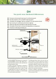
1.7 Quick start guide<br />
This chapter is only a summary of following chapters. Please read<br />
the complete manual carefully before using the instrument.<br />
In general, the <strong>T8</strong> is filled and ready for installation when supplied.<br />
1. Drilling the borehole:<br />
Mark the required drilling depth on auger and on Tensiometer shaft.<br />
Note: drilling depth = Installation depth / cos α.<br />
For installation from the soil surface, an installation angle of 25° to<br />
65° from the vertical line is ideal for the optimal removal of air from<br />
the cup (fig. a). For “horizontal” installation from a manhole the<br />
borehole should point upwards in an angel of 5° (fig. b).<br />
2. Slurrying the cup is only recommendable in clayey soils and only if<br />
the bore hole is larger than 24 mm. In coarse sand or pebbly soils<br />
fine pored slurry might create a water reservoir which slows down<br />
the response. With the special Tensiometer gouge auger (article no.<br />
TB-25) slurrying is unnecessary because of the accurate fitting of the<br />
Tensiometer in the soil.<br />
3. Take off the protective plastic bottle from the Tensiometer cup. Tilt<br />
and pull the bottle off carefully. If necessary, carefully turn it counterclockwise!<br />
4. Insert the <strong>T8</strong> into the hole to the depth mark without using force.<br />
In clayey soils a dangerous overpressure might<br />
develop: Check the tensiometer's pressure reading<br />
with an Infield measuring device or a data logger!<br />
Important: Pay attention to the yellow sticker with<br />
the dot on the shaft’s top end that marks the<br />
position of the exit opening of the external filling<br />
inside the cup:<br />
a) Downwards installation: If the position of the cup<br />
will be lower than the end of the shaft, the yellow<br />
sticker must exactly face up!<br />
(a)<br />
(b)<br />
b) Upwards installation: If the position of<br />
the cup will be higher than the end of the<br />
shaft, the yellow sticker must exactly face<br />
down!<br />
8/56
Tensiometer <strong>T8</strong><br />
External syringe refilling<br />
Installed <strong>T8</strong> can be refilled or ventilated through the<br />
two capillary tubes (stainless steel) without being<br />
removed from the soil. The tubes can be extended.<br />
With the supplied refilling syringe a measuring range of<br />
at least -80 kPa can be assured. With the special<br />
Refilling Kit BKT456 a range of -85 kPa can be<br />
assured.<br />
Reference air pressure<br />
The reference atmospheric air pressure is conducted<br />
to the pressure transducer via the water impermeable<br />
(white) Teflon membrane and through the cable.<br />
The membrane must always have contact to the air<br />
and should never be submersed into water.<br />
Optional protective plastic tube<br />
Available as accessory<br />
Cable gland (IP67)<br />
The <strong>T8</strong> can be completely buried if required. Cables<br />
and tubes of buried <strong>T8</strong> should be protected. Special<br />
cable glands are available for tight connection of a<br />
Shaft<br />
One-piece shafts from 10 cm to 200 cm are available.<br />
Shafts over 200 cm are divided with threaded adapter.<br />
Sensor body incl. electronics<br />
Direct connection between internal power converter to<br />
6-18 VDC<br />
Pressure sensor<br />
The piezoelectric pressure sensor measures the soil<br />
water tension against atmospheric pressure<br />
Temperature and level indicator<br />
High grade porous ceramic cup<br />
Filled with degassed water.<br />
9/56
Tensiometer <strong>T8</strong><br />
5. Push down the shaft water retaining disk to a position directly on<br />
the soil surface.<br />
6. Slide on the thermal insulation tube over the capillary filling tubes.<br />
7. If the plug is not connected right away leave the protective cap on<br />
the plug. Water tightness is only assured when the plug is kept<br />
clean.<br />
8. Connect the Tensiometer signal wires as specified (see chapter<br />
„Connecting the <strong>T8</strong>”)<br />
The <strong>T8</strong> can be connected to:<br />
• data loggers with analog input or serial RS485 or SDI12,<br />
• a PC or laptop via tensioLINK bus as a standalone sensor or<br />
within a sensor network,<br />
• an additional 6 V Battery to run the <strong>T8</strong> in the auto-logging<br />
function (internal data logger, requires tensioVIEW software and<br />
USB converter for configuration),<br />
• the INFIELD7 for taking spot readings or downloading stored<br />
readings.<br />
Please note:<br />
Especially in loamy, clayey soils a high pressure can occur just by<br />
inserting the <strong>T8</strong> into the borehole. Thus, the pressure values<br />
should be continuously observed during installation, either with the<br />
INFIELD7 handheld or online with laptop, USB Converter and<br />
tensioVIEW.<br />
Note for the latter that the readings are refreshed only every 5<br />
seconds by the internal microprocessor.<br />
The less air is inside the cup and the better the soil's conductivity<br />
is, the faster the Tensiometer will respond to tension changes.<br />
If the soil is dryer than -90 kPa, it does not make sense to refill the<br />
Tensiometer. The refilling procedure will be done best at the time<br />
when the Tensiometer installed in the next lower level has reached<br />
the value of drying off of the upper Tensiometer.<br />
10/56
Description of the <strong>T8</strong><br />
2 Description of the <strong>T8</strong><br />
2.1 <strong>T8</strong> parts<br />
2.1.1 Body and shaft<br />
The whole electronics are integrated in the body of the <strong>T8</strong>. The<br />
housing is made of fiberglass reinforced plastic. The electronic is<br />
completely sealed and thus well protected against moisture.<br />
2.1.2 Pressure sensor<br />
The piezoelectric pressure sensor measures the soil water tension<br />
against the atmospheric pressure. The atmospheric pressure is<br />
conducted through a watertight diaphragm (the white, 2 cm long tube<br />
on the cable) and through the cable to the reference side of the<br />
pressure sensor.<br />
The non destructive maximum pressure is ±3 bar (300 kPa).<br />
Higher pressure will damage the sensor and absolutely must be<br />
avoided! High pressures can appear for example when cup and<br />
sensor are reassembled, when inserted in wet, clayey soils or in<br />
tri-axial vessels.<br />
2.1.3 Reference air pressure<br />
The reference atmospheric air pressure is conducted to the pressure<br />
transducer via the air permeable (white) Teflon membrane and<br />
through the cable. The membrane does not absorb water. Water will<br />
not pass through the membrane into the cable, but condensed water<br />
inside the cable will leave the cable through the membrane.<br />
The white membrane on the cable must always have contact to air<br />
and should never be submersed into water.<br />
2.1.4 Temperature sensor<br />
A temperature probe with a tolerance of ±0,2 K at 10 °C is used.<br />
The tip of the temperature sensor dips into the Tensiometer cup's<br />
water. Thus, the best possible thermal contact to the soil is achieved.<br />
11/56
Description of the <strong>T8</strong><br />
2.1.5 Filling status indicator<br />
The filling status indicator indicates the filling status of a <strong>T8</strong> in a<br />
downwards installation (cup lower than end of the shaft).<br />
If the Tensiometer is installed in an upward angle (cup higher than<br />
the end of the shaft), the water will still cover the indicator even if<br />
air is already inside the cup. Thus, the indicator will react not<br />
before the cup is almost completely empty (s. fig. 5.3 on page 38).<br />
The filling status is determined by measuring the heat flux with the<br />
internal temperature probe. For a probe dipped into water the heat<br />
flux rate is lower than in air. If an air bubble appears around the<br />
temperature probe, the heat flux rate rises and the insufficient filling<br />
status is detected. This method offers a rough but reliable reference<br />
for checking the filling and has the advantage of staying stable over<br />
the whole lifespan of the Tensiometer. It replaces the previously use<br />
IR-photo diode. The measurement of the soil water tension is not<br />
influenced.<br />
Benefits of the filling status indicator are an optimal service: If for<br />
example mounting rails with integrated LEDs are used, the user can<br />
check at a glance if all Tensiometers work well or which need to be<br />
refilled.<br />
Also, for quality assurance, the status of the signal can be logged for<br />
later evaluation of the readings.<br />
2.1.6 The ceramic cup<br />
To transfer the soil water tension as a negative pressure into the<br />
Tensiometer, a semi-permeable diaphragm is required. This must<br />
have good mechanical stability and water-permeability, but also have<br />
gas impermeability.<br />
The <strong>T8</strong> cup consists of ceramic Al2O3 sinter material. The special<br />
manufacturing process guarantees homogeneous porosity with good<br />
water conductivity and very high firmness. Compared to conventional<br />
porous ceramic the cup is much more durable.<br />
The bubble point is at least 1500 kPa (15 bar). If the soil is dryer than<br />
1500 kPa the negative pressure inside the cup decreases and the<br />
readings go down to 0 kPa.<br />
With these characteristics this material has outstanding suitability to<br />
work as the semi permeable diaphragm for Tensiometers.<br />
The cup has a lifetime guarantee against breakage.<br />
12/56
Description of the <strong>T8</strong><br />
2.2 Output signals<br />
2.2.1 Analog<br />
The <strong>T8</strong> version 2005 has an internal microprocessor and offers water<br />
tension and temperature as analog output signals plus the refilling<br />
status as a digital signal.<br />
Water tension and temperature are available as linear voltage<br />
signals in a selectable range of 0...1 V, 0...2 V (default setting) or<br />
0...5 V. Thus, the <strong>T8</strong> are compatible to almost any data logger or<br />
data acquisition system.<br />
Furthermore, the measuring range itself can be set for special<br />
measuring tasks. Standard is +100 kPa to -100 kPa and -30 to<br />
+70°C.<br />
The standard setting for the filling status is either switch “open” (0 V)<br />
or “closed” (voltage signal equal to power supply voltage).<br />
2.2.2 Digital<br />
To change the settings of signal range or use the serial interface of<br />
the <strong>T8</strong> the tensioLINK ® USB converter with Windows software<br />
tensioVIEW ® is available as an accessory.<br />
Filling status as a Digital Status<br />
If the indicator detects an air bubble the indicator switch closes and<br />
the supply voltage is available on the output. If for example a LED<br />
with a series resistor is connected, the LED will light up to indicate<br />
the necessity of refilling. In addition, or instead, connect the signal to<br />
a digital or analogue logger channel to record the filling status for<br />
quality control of the matrix potential readings.<br />
2.3 Serial interfaces<br />
The <strong>T8</strong> has two serial interfaces: the RS485 compatible tensioLINK<br />
interface and SDI12.<br />
13/56
Description of the <strong>T8</strong><br />
2.3.1 tensioLINK ®<br />
To use the serial interface the tensioLINK ® USB converter with<br />
Windows software<br />
tensioVIEW ® is required.<br />
tensioLINK ® is RS485<br />
based and used for all<br />
functions, for taking<br />
online readings, for<br />
uploading stored data<br />
and for configuration of<br />
the <strong>T8</strong>.<br />
RS485 allows a robust<br />
and cost effective bus<br />
linkage of sensors with<br />
cables of up to a few<br />
kilometers. Data loggers<br />
with RS485 interface can<br />
directly read sensors.<br />
Please contact <strong>UMS</strong> for a<br />
description of the data<br />
protocol.<br />
2.3.2 SDI12<br />
Additionally a SDI12 interface is integrated for connection to SDI12<br />
systems. The SDI12 interface has to be activated via tensioVIEW ® .<br />
Then, one of the 2 analog outputs is used as the SDI12 data line.<br />
14/56
Description of the <strong>T8</strong><br />
2.4 Software<br />
2.4.1 tensioVIEW<br />
The Windows software tensioVIEW ® (supplied with the tensioLINK-<br />
USB converter) automatically detects all tensioLINK devices linked<br />
within a bus network. The software is used for the configuration of<br />
these devices and for displaying data.<br />
tensioVIEW ® shows for example the settings of a VS vacuum station<br />
or <strong>T8</strong> readings from the recent days.<br />
When used in a laboratory no other device is required beside<br />
tensioLINK, tensioVIEW and PC to have a complete data acquisition<br />
system. Readings are displayed and stored by the PC directly.<br />
2.5 Sensor logging<br />
<strong>UMS</strong> Tensiometer <strong>T8</strong> and TS1 have an internal non-volatile data<br />
memory. When connected to a power supply readings of soil water<br />
tension and soil temperature are taken and stored in selectable<br />
intervals of 1 minute to 24 hours. The <strong>T8</strong> has a capacity of 4000<br />
readings which, with an interval of 1 hours, is enough for 166 days of<br />
measurements.<br />
In this mode of operation the power consumption is very low, so<br />
modest battery capacities are<br />
sufficient even for long<br />
measuring periods.<br />
To run stand-alone sensors a<br />
battery box is available as an<br />
accessory. The weatherproof<br />
box is fitted with a tensioLINK<br />
plug for uploading the data<br />
stored in the sensor.<br />
15/56
Installation<br />
3 Installation<br />
3.1 Concept planning and installation<br />
3.1.1 Selecting the measuring site<br />
The installation spot should be representative for the soil horizon!<br />
Therefore, in heterogenic soils, classifying drillings should be made<br />
before or during installation.<br />
On farmed sites with vegetation root spreading and root growth<br />
during the measuring period must be considered. Fine roots will grow<br />
around the Tensiometer cup as this is a poor but still secure source<br />
of water. Therefore, avoid the root zone or move the Tensiometer<br />
from time to time depending on the root growth.<br />
Disturbing effects like waysides, the rim of a field, slopes or dints<br />
must be avoided or considered in the interpretation of the measuring<br />
results.<br />
3.1.2 Number of Tensiometers per level<br />
The lower the level the less the variations of water potentials are. In<br />
sandy or pebbly profundities one Tensiometer per depth is sufficient.<br />
Close to the surface about 3 Tensiometers per level are<br />
recommendable.<br />
Guiding principle: More heterogeneous sites and soil structures<br />
require a higher number of Tensiometers.<br />
3.1.3 Extension of the site<br />
Large distance along with high equidistance between the measuring<br />
spots will reduce the influence of sectional heterogeneity.<br />
To obtain a differential description of the soil water situation at least<br />
2 Tensiometers are recommended per horizon, one in the upper and<br />
one in the lower level.<br />
Cable lengths of 100 meters and more are possible (see chapter 8.2<br />
for cables) but should be avoided for the following reasons:<br />
• Accuracy: with a single-ended connection each 10 meter of<br />
cable causes a reduction of the accuracy. (See chapter 3.3.1 for<br />
compensation of current drop with single-ended connections)<br />
16/56
Installation<br />
• Lightning: cables act as antennas and should always be as short<br />
as possible.<br />
3.1.4 Protection of refilling tubes<br />
A recent study by Prof. Wolfgang Durner showed that refilling<br />
tubes must be protected from heating up and solar radiation.<br />
If a bubble assembles inside a refilling tube, temperature changes<br />
will lead to an expansion of the air resulting in a variation of the<br />
reading. Therefore, refilling tubes should be as short as possible and<br />
should be thermally protected, either by providing an insulating<br />
protection or by burying the tubes.<br />
Thermal effect:<br />
As long as the Tensiometer and its tubes are freshly and completely<br />
filled it will work perfectly. Any air trapped<br />
inside the upper parts of the tube will expand<br />
when heated up by solar energy. This causes<br />
a drop of the water tension and some water<br />
will flow from the cup into the ground.<br />
Thus, readings will fluctuate around the actual<br />
reading during solar radiation, especially with<br />
low water potentials. Furthermore, under<br />
permanent solar exposure the tubes get sticky<br />
and brownish.<br />
Slide the supplied thermal insulation tube over the shaft end , the<br />
refilling tubes and sensor cable as shown in above photo. Please<br />
keep a distanz of approx. 5 cm to the soil surface to avoid ant<br />
population inside the tube!<br />
17/56
Installation<br />
3.1.5 Jacket tubes<br />
Jacket tubes are useful with shafts longer than 2 m, in pebbly soils or<br />
gravel, and for horizontal installations from inside a well or pit hole.<br />
The jacket tube should end 30 to 50 cm away from the cup so<br />
leaking or condensation water is not conducted to the cup. The inner<br />
diameter of the jacket tube should be at least 35 mm.<br />
3.1.6 Ideal conditions for installation<br />
For the installation of Tensiometers, the ideal conditions are:<br />
• Frost-free soil.<br />
• Wet coarse clay or loess.<br />
• Low skeletal structure (gravel). The more gravel in a soil the<br />
more often the drilling has to be repeated to reach the required<br />
depth.<br />
3.1.7 Documentation<br />
For every measuring spot you should:<br />
• Measure out the position where the pressure sensor will be<br />
placed. (A must for installations below the ground surface).<br />
• Take documenting photos before, during and after installation.<br />
• Save a soil sample.<br />
• Write down installation depth and angle with the sensor<br />
identification (serial number).<br />
• Mark all connecting cables with the corresponding sensor<br />
identification, serial number or logger channel on each end. Clipon<br />
number rings are available as an accessory (see chapter 9.2).<br />
3.2 Selecting the installation angle<br />
An installation position would be ideal if the typical water flow is not<br />
disturbed by the Tensiometer. No preferential water flow along the<br />
shaft should be created. Therefore, Tensiometers are preferably<br />
installed at an angle.<br />
18/56
Installation<br />
3.2.1 "Vertical" with downwards angle<br />
When installed from the surface, an angle of 25° to 65°<br />
from the vertical is optimal for refilling. In an absolutely<br />
vertical position air bubbles might inside the edges of<br />
the cup adapter. Still, they could be removed<br />
completely with the vacuum refilling kit BKTex. In this<br />
position, the refilling tube is the shorter stainless steel<br />
tube with the yellow sticker. Into this tube, water is<br />
injected for refilling.<br />
Before inserting the Tensiometer, turn the shaft so<br />
the yellow sticker near the shaft end points upwards.<br />
Do not turn the shaft after it is inserted into the ground as this<br />
might loosen the cup.<br />
3.2.2 "Horizontal" or upwards installation angle<br />
When installed horizontally or upwards from inside a well or pit hole,<br />
the shaftmark must look downwards! An upward angle of approx. 5°<br />
is ideal for refilling. Note that now de-airing and refilling tube are<br />
switched: the refilling tube is the longer<br />
stainless steel tube without the black<br />
mark. Into this tube, water is injected for<br />
refilling.<br />
Before inserting the Tensiometer, turn<br />
the shaft so the yellow sticker near the shaft end points<br />
downwards.<br />
Do not turn the shaft after it is inserted into the ground as this<br />
might loosen the cup.<br />
Note that with a horizontal installation the filling indicator will not<br />
react much later, - if installed upwards not before until the cup is<br />
almost empty.<br />
3.3 Installation procedure<br />
For the installation of the <strong>T8</strong> in the field the following tools are<br />
required:<br />
• Tensiometer auger with diameter 25 mm, ideally the <strong>UMS</strong> gouge<br />
auger with shaped blade tip.<br />
19/56
Installation<br />
• Rule, spirit level, angle gauge, marker pen.<br />
• Minute book, camera for documentation of site and soil profile.<br />
• Perhaps PE-plastic bags for taking soil samples from the site.<br />
• Thermal insulation tubes for installations from soil surface.<br />
• Cable protection tubes.<br />
• Jacket tubes if required (inner diameter > 35 mm).<br />
Please observe the following notes:<br />
Do not touch the cup with your fingers. The ceramic should not<br />
have contact with grease or soap as this will influence the<br />
hydrophilic performance.<br />
Do not leave the cup in air for more than 5 minutes as<br />
Tensiometer water will evaporate and the Tensiometer will need to<br />
be refilled.<br />
Procedure:<br />
1. Mark the required drilling depth on auger and Tensiometer shaft.<br />
The reference point is the center of the cup. Drill a hole with the<br />
desired depth on the chosen measuring spot. Auger stepwise<br />
and take care when drilling the last 20 cm, remove and save this<br />
soil. Water will not run along the shaft if the Tensiometer is<br />
installed in an angle because the water will drain into the soil<br />
before it reaches the cup.<br />
Read the chapter "Selecting the installation position" for the best<br />
installation angle.<br />
2. When using augers with a diameter of over 25 mm, mix a paste<br />
of water and crumbled soil material taken out of the borehole. Fill<br />
the paste into the bottom area of the borehole by using a simple<br />
pipe with outer diameter 2 cm.<br />
3. Now take off the protective plastic cap from the Tensiometer cup.<br />
Important: Do not turn, but pull when taking the bottle off - and<br />
also when putting it back on again!<br />
Save the plastic bottles: Do not store the Tensiometer without the<br />
protective plastic bottle since the cup drains fast! The bottle must<br />
be filled with some water for storage!<br />
20/56
Installation<br />
4. Connect the Tensiometer to a readout unit. Check the position of<br />
the yellow sticker. Carefully insert the <strong>T8</strong> into the borehole up to<br />
the stop while continuously observing the pressure signal. Using<br />
the TB25 auger you feel a light resistance at the last 6 cm<br />
indicating proper soil contact of the ceramic.<br />
Do not use any force. Do not hit the Tensiometer - this may<br />
damage cup and pressure sensor.<br />
Especially in clayey soils the pressure reading must be monitored<br />
as high pressures might build up! The pressure must not exceed<br />
200 kPa<br />
5. Press the soil surface with your boots gently to the shaft to close<br />
the gap.<br />
6. Push the shaft water retaining disk down to cover the soil<br />
surface. This prevents water from running down into the<br />
borehole along the shaft.<br />
7. Leave the protective plastic cap on the plug whenever the plug is<br />
not connected!<br />
8. Connect the signal cables as described in the chapter<br />
"Connecting the <strong>T8</strong>".<br />
9. The Tensiometer will respond to changes in the soil water<br />
tension faster if there is no air inside the system and the soil<br />
water conductivity is high.<br />
10. Write down the serial number, position, installation angle and<br />
depth.<br />
11. Slide the supplied thermal insulation tube over the shaft end and<br />
the refilling tubes. Bend the signal cable and lead it back through<br />
the thermal tube.<br />
12. Protect the cables against rodent bites. Lead the cables through<br />
plastic pipes or use the plastic protection tubes which are<br />
available as an accessory.<br />
21/56
Installation<br />
3.4 Offset correction for non horizontal installations<br />
The pressure transducer is calibrated without<br />
Transducer a cup. Thus, no compensation is required for<br />
horizontal installations.<br />
If a <strong>T8</strong> is installed in a non horizontal<br />
position, the vertical water column draws on<br />
5cm the pressure sensor and causes an offset<br />
shift.<br />
Middle of cup Compensate the offset:<br />
• by calculation,<br />
• by entering the installation angle in the<br />
Infield7 for spot readings,<br />
• in the configuration of a data logger by<br />
setting an offset,<br />
• by storing the installation angle directly inside the installed <strong>T8</strong><br />
through the tensioLINK interface.<br />
The middle of the cup is regarded to be the measuring level. The<br />
correction is largest for a vertical water column (at 0 o ) and varies as<br />
the cosine of the installation angle, as shown on the table below. In<br />
an absolutely horizontal position the offset is zero.<br />
Example: A 5 cm vertical column of water below the pressure<br />
sensor will create an 0.5 kPa offset. This means that when the soil<br />
water tension is 0 kPa the sensor will indicate -0.5 kPa.<br />
Table showing the offset correction when a 5 cm column of water is<br />
tilted at various angles:<br />
Angle to vertical line 0° 10° 15° 20° 25° 30°<br />
Offset correction in [kPa] +0,5 +0,49 +0,48 +0,47 +0,45 +0,43<br />
Angle to vertical line 45° 60° 70° 75° 80° 90°<br />
Offset correction in [kPa] +0,35 +0,25 +0,17 +0,13 +0,09 0<br />
The offset is entered as + in your logger if you regard the soil water<br />
tension to be negative (0 ... -85 kPa).<br />
22/56
Installation<br />
3.5 Connecting <strong>T8</strong><br />
3.5.1 Spot reading with the INFIELD7 handheld<br />
The <strong>T8</strong> is fitted with an 8-pin plug. The plug can be connected to an<br />
INFIELD7 handheld measuring device. The INFIELD7 displays and<br />
stores the soil water tension, the soil temperature and the filling<br />
status.<br />
3.5.2 Connection to a data logger<br />
For connecting <strong>T8</strong> to a data logger or any other data acquisition<br />
devices connecting and extension cables are required. Find <strong>T8</strong><br />
cables in the chapter “Accessories”.<br />
The supply voltage does not has to be stabilized.<br />
If the Tensiometer is not permanently powered the warm-up<br />
before a measurement should be at least 10 seconds.<br />
The Tensiometer plug should be covered with the supplied<br />
protective cap anytime the <strong>T8</strong> is not connected to an extension<br />
cable.<br />
Never connect the signal outputs of the <strong>T8</strong> to a supply voltage<br />
source!<br />
The supply voltage must not exceed 18 VDC.<br />
Tightly screw together all plugs of connecting cables (CC-8/...) or<br />
extension cables (EC-8/...). Do this again after a few minutes as<br />
only then the connections will be absolutely water proof.<br />
23/56
Installation<br />
3.5.3 Error caused by single-ended connection<br />
In general a data logger with differential inputs should be preferred.<br />
This means both the plus signal as well as the minus signal of each<br />
sensor are measured. On many data loggers less channels are<br />
required for single-ended measurements, which means only the plus<br />
signals are measured and related to the common sensor supply<br />
ground. In this case, the voltage drop, depending on the current<br />
consumption and the cable resistance, influences the reading and<br />
must be compensated for:<br />
Example: Current consumption 3 mA; cable resistance: 0,082 Ω/m<br />
(for <strong>UMS</strong> standard cable and signal range 0 ... 2 V)<br />
Voltage drop inside a cable with length 10 m:<br />
U Error/10m cable = R x I = 0,82 Ω x 3 mA = 2,5 mV<br />
Error for water tension (1 mV equal to 0,1 kPa): 2,5 mV = 0,25 kPa<br />
Error for temperature (1°C equal to 20 mV): 2,50 mV = 0,25 K<br />
Thus, the signal is lifted for +0,25 kPa and +0,1 K per 10 m cable.<br />
With the standard signal range 0...2 V the readings will be:<br />
for 100 kPa = 2,5 mV and -30°C = 2,5 mV (instead of 0 mV)<br />
for -100 kPa = 2002,5 mV and +70°C = 2002,5 mV (instead of 2000<br />
mV).<br />
Change the offset correction in the data logger accordingly.<br />
The signal gradient (conversion factor) is not changed by the voltage<br />
drop.<br />
3.5.4 Connecting the indicator<br />
Some data logger types require a pull-down resistor (for example 10<br />
kOhm) against ground for the indicator (Pull down resistor).<br />
The external pull-down resistor must be smaller than the logger<br />
internal pull-up resistor, or at least be in a relation so the logger will<br />
recognize the zero level. Please contact <strong>UMS</strong> if you have questions<br />
regarding the indicator connection.<br />
24/56
<strong>T8</strong> configuration with tensioVIEW®<br />
4 <strong>T8</strong> configuration with tensioVIEW ®<br />
4.1 tensioLINK ® USB converter<br />
The power supply of the tensioLINK ® converter is galvanically<br />
isolated from the PC or Laptop and can be used to power connected<br />
sensors. The 8-pin <strong>T8</strong> plug has the standard tensioLINK ® plug<br />
configuration and can be directly connected to the converter without<br />
the need of any further items.<br />
Bus distribution modules are available to link numerous sensors. Any<br />
custom made cables require 4 wires for a parallel connection of all<br />
sensors.<br />
If sensors should be supplied by another power source take notice to<br />
avoid potential differences. This can be achieved by connecting the<br />
GND of both power sources. The V+ line of the USB converter then<br />
is not used.<br />
4.2 Work with tensioVIEW<br />
4.2.1 Menu<br />
tensioVIEW ® has a simple menu for mostly self-explaining read-out<br />
and configuration of tensioLINK devices.<br />
After starting tensioVIEW the display is more or less blank, most<br />
functions are inactivated.<br />
Search devices<br />
If one or more sensors are connected via the USB-converter<br />
they can be searched by pressing the “magnifier” button.<br />
tensioVIEW ® offers two options for searching:<br />
Single device mode<br />
tensioVIEW ® expects that only one device is connected which<br />
will be found very quick. This mode is not functional if more<br />
than one device is connected!<br />
25/56
<strong>T8</strong> configuration with tensioVIEW®<br />
Multiplex device modes<br />
tensioVIEW ® is able to detect up to 256 devices connected to<br />
the bus within 8 seconds, but only if each device is already<br />
personalized with an individual bus identification address. If two or<br />
more devices have an identical address, none of them will be found.<br />
All devices found will be displayed in the left section as a directory<br />
tree. Same types of devices will be grouped in one directory.<br />
Fig. 4.1: Found devices in tensioVIEW<br />
Detected devices will be displayed with their programmed names.<br />
Press the + symbol to see what readings the device can offer.<br />
Double-click on the name to open a menu window where all<br />
specifications and functions of this device are displayed. Depending<br />
on the type different registries are available. The first shows an<br />
overview of the current settings and information about address<br />
number or error messages.<br />
26/56
<strong>T8</strong> configuration with tensioVIEW®<br />
4.2.2 Current readings<br />
Enter the interval parameters and press ”Start” to display the current<br />
readings.<br />
4.2.3 Stored readings<br />
Open the menu “Stored readings“ to upload the data from a <strong>T8</strong> (if<br />
logging had been activated in the logger menu)<br />
4.2.4 Configuration of a device<br />
Select the register "Configuration“ for viewing and changing the<br />
programmed settings of the device.<br />
Depending on the authorization status, only parameters that can be<br />
edited are shown. To store it in the device. a changed parameter has<br />
to be sent to the device by pressing the "Upload“ button. A message<br />
notifying about the successful configuration will be displayed.<br />
Configuration changes are effective immediately. Tensiometers for<br />
example will re-start just as if they were connected to power.<br />
4.3 Configuration settings for <strong>T8</strong><br />
Those settings which are editable only for Power users are marked<br />
with an asterisk *.<br />
Parameters with related functions are bundled in one folder.<br />
27/56
<strong>T8</strong> configuration with tensioVIEW®<br />
Figure 4.2: Configuration menu<br />
tensioLINK<br />
Bus number<br />
tensioLINK bus number of the device<br />
Sub address<br />
tensioLINK sub address of the device<br />
Explanation:<br />
tensioLINK uses two types of address for each device, the bus<br />
address and the sub address. The reason for this is that is there<br />
might be sensors installed at the same spot, but with different<br />
measuring depths (for example multi-level probes). In this case, the<br />
sub address defines the depth starting with 1 for the highest sensor.<br />
Furthermore, the sub address could be used to combine groups of<br />
sensors, for example of one measuring site.<br />
In general the required identification for a device is always the bus<br />
number. If more than 32 devices are connected to the bus the sub<br />
28/56
<strong>T8</strong> configuration with tensioVIEW®<br />
address is counted up. The allowed numbers for the bus address are<br />
1 to 32 and for the sub address 1 to 8.<br />
The default value for both bus and sub address is 0. With more than<br />
one device connected individual addresses have to be declared.<br />
Serial interface activated during power down*<br />
Serial reception possible in sleep mode. When data are received<br />
thorough the RS485 interface the <strong>T8</strong> is wakened, With an activated<br />
reception the <strong>T8</strong> consumes approximately an additional 0.5 mA.<br />
Device information<br />
Device name<br />
Individually editable name of the Tensiometer in ASCII. Maximum<br />
length 12 digits<br />
Calibration date<br />
Date of the last calibration. In general sensors should be recalibrated<br />
and checked after two years.<br />
Installation depth<br />
Here the installation depth can be entered. This is for your<br />
information only and has no further functions.<br />
Installation angle<br />
Installation angle selectable from 0° to 180°. If activated the water<br />
column inside the ceramic cup will be compensated in relation to the<br />
installation angel. (0° means the Tensiometer is installed vertically).<br />
Soil type<br />
Type of soil at the installation site: Only for information, does not<br />
influence the Tensiometer readings.<br />
Ceramic Type*<br />
For special ceramics for compensation of the installation angle only.<br />
Compensation length<br />
Effective length of the total water column in [0.1 cm] for<br />
compensation of the installation angle.<br />
Data logger<br />
Interval<br />
Logging interval of the internal logger<br />
Ring buffer memory<br />
29/56
<strong>T8</strong> configuration with tensioVIEW®<br />
With ring buffer activated the oldest readings are overwritten when<br />
the memory space is full.<br />
System<br />
The Power Save Mode puts the Tensiometer to sleep when inactive.<br />
Analog outputs are then switched off and the current consumption is<br />
significantly reduced. If data is read out only serially, or the internal<br />
data logger is used, activate this option without reducing the<br />
Tensiometer operation. Possibly the Tensiometer will react a little bit<br />
slower to serial commands.<br />
Sensor readings<br />
Continuous measurements<br />
Activate the quick updating of readings to receive the Tensiometer<br />
readings instantly, for example during a refilling procedure.<br />
Measurements are taken in intervals of 50 ms. Note the rise in power<br />
consumption and that the reaction to serial commands might be<br />
slowed down. The setting "Measuring interval“ is deactivated during<br />
this mode..<br />
Measuring interval<br />
This is the standard interval in which sensor measurements are<br />
refreshed and available on the analog lines.<br />
30/56
<strong>T8</strong> configuration with tensioVIEW®<br />
Figure 4.4: Configuration menu: sensor measurements<br />
Analog Outputs (DAC)<br />
DACA active<br />
Turns on the analog output 1 (standard use pressure)<br />
DACB active<br />
Turns on the analog output 2 (standard use temperature)<br />
Associate reading DACA<br />
A sensor reading can be associated to analog output 1. Standard for<br />
analog output 1 is pressure.<br />
Associate reading DACB<br />
A sensor reading can be associated to analog output 2. Standard for<br />
analog output 2 is temperature.<br />
Associate depth DACA<br />
For multilevel probes the DACA reading can be associated to a<br />
certain depth. Then, tensioLINK will take readings using the same<br />
31/56
<strong>T8</strong> configuration with tensioVIEW®<br />
bus address plus the sub address. For the default value depth = 1<br />
the internal sensor readings are used.<br />
Associate depth DACB<br />
Associate a depth to reading DACB.<br />
DAC error output<br />
Error output value for DAC [mV]. If an incorrect reading occurs (e. g.<br />
filling status insufficient) this voltage value will be put on the analog<br />
output.<br />
DAC output range<br />
Set the output range of the analog reading to 0 to 1 V; 0 to 2 V or 0<br />
to 5 V. A sensor reading will be amplified within this range, for<br />
example -100 kPa to +100 kPa can correspond to 0 to 2 V.<br />
DAC temperature output range<br />
Output range for temperature.<br />
DAC pressure output range<br />
Output range for pressure.<br />
Digital output<br />
Digital output power saving<br />
Activate the power saving function of the digital output. Any burden<br />
connected to the digital output will be powered shortly every 5<br />
seconds (e. g. a LED will blink every 5 s indicating a malfunction)<br />
Function of the digital output<br />
Evaluation through a table. If the digital output is used for control of<br />
the filling status, 1 indicates a poor filling status.<br />
If used as a comparator the value of a reading is compared to the set<br />
threshold (see "Lower threshold"). If used as a window comparator<br />
the reading is compared with both threshold values. In case the<br />
reading is in between both threshold values the digital output is set to<br />
1.<br />
Associate reading to digital output<br />
This is the relevant reading for the comparator.<br />
Associate depth to digital output<br />
The depth value for comparator, 1 = individual sensor (see<br />
"Associate depth DACA“)<br />
Invert digital output function<br />
If enabled all digital output functions will be inverted.<br />
Lower threshold integer<br />
Integer part of the lower threshold or window threshold value.<br />
32/56
<strong>T8</strong> configuration with tensioVIEW®<br />
Upper threshold integer<br />
Integer part of the upper window threshold.<br />
Lower threshold decimal<br />
Decimal part of the lower threshold or window threshold.<br />
Upper threshold decimal<br />
Decimal part of the upper threshold or window threshold.<br />
Configuration example for the digital output:<br />
Function of the digital output = comparator<br />
Associated reading on digital output = temperature<br />
Integer part of the lower threshold = 24<br />
Decimal part of the lower threshold = 3<br />
if temperature is higher than 24.3° the digital output is set to 1.<br />
Filling status testing<br />
Measuring interval<br />
Interval in which the filling status is checked with the Thermistor<br />
(BDT) method.<br />
33/56
Service and maintenance<br />
5 Service and maintenance<br />
5.1 Refilling<br />
To assure a rapid and reliable measurement of the soil water<br />
tension, the cup must be filled possibly bubble-free with degassed<br />
water. After dry periods or periods with a large number of wet and<br />
drying out successions, the <strong>T8</strong> must be refilled.<br />
The following items are required for all refilling methods:<br />
• Syringe with valve (one supplied with each order)<br />
• Degassed, de-ionized or distilled water<br />
• Measuring device for checking the pressure signal<br />
Simple method to degas water:<br />
The best way to degas water is by using a syringe.<br />
• Draw up water into the syringe until it is 2/3 filled. Close the valve<br />
or block the syringe with your finger.<br />
• Now draw up the syringe as far as possible to create a vacuum<br />
inside. Rotate the syringe to create one big bubble.<br />
• Take of your finger or open the valve and squeeze out the<br />
bubble.<br />
Repeat this procedure a few times.<br />
5.1.1 When do Tensiometers need to be refilled?<br />
Tensiometers need to be refilled:<br />
• when the IR indicator will light up (for Tensiometers installed<br />
"downwardly"),<br />
• the curve of the readings apparently gets flatter (for example a<br />
rain event has no sharp peak but is round),<br />
• the maximum of -85 kPa is not reached anymore.<br />
Refilling is only reasonable if the soil is moister than -90 kPa or<br />
if a lower level installed Tensiometer shows wetter readings<br />
again<br />
If the soil gets dryer than -85 kPa, the readings will remain constant<br />
at the vapor pressure of water (i. e. for example 92,7 kPa at 20°C<br />
and atmospheric pressure of 95 kPa). By diffusion and slight leakage<br />
the reading will slowly drop within months.<br />
34/56
Service and maintenance<br />
If the soil dries out more than -1500 kPa (-15 bar), the negative<br />
pressure will drop much faster as air will enter the cup.<br />
5.1.2 Refilling in the lab<br />
To reach the optimal measuring range of -90 kPa Tensiometers<br />
should be refilled in the laboratory using the refill kit.<br />
1. Set up the refilling kit and connect the vacuum pump as shown in<br />
the photo. The pump should achieve at least 0,8 kPa against<br />
vacuum. Use distilled or de-ionized water which necessarily does<br />
not have to be degassed when a pump is used.<br />
2. Unscrew the cup in clockwise direction and empty it.<br />
Do not touch the ceramic cup with your fingers. Wrap a clean<br />
towel around the cup!<br />
The pressure sensor diaphragm is inside the small hole on the<br />
pressure sensor body. It is very sensitive and may never be<br />
touched! It can be destroyed even by slightest contact!<br />
No contamination should get on the sealing and gasket.<br />
3. If the cup is dry it should be placed in a beaker filled with distilled<br />
water for several hours or overnight. Initially there should be no<br />
water inside the cup! Place the empty cup into the beaker in an<br />
upright position, with the external water level reaching no higher<br />
than 2/3 of the cup.<br />
If the cup is filled with water and water intrudes from both inside<br />
and outside cavities of air will be enclosed inside the ceramic.<br />
Adaptor for<br />
sensor body<br />
Vacuum gauge<br />
Adaptor for<br />
ceramic cup<br />
Fig. 5.1: <strong>UMS</strong> laboratory refill kit BKT468<br />
Connection to vacuum<br />
pump<br />
35/56
Service and maintenance<br />
4. Insert the saturated but empty cup to the adapter and connect it<br />
to the degassing device. Place the cup in water in an upright<br />
position.<br />
5. Fill the second <strong>UMS</strong> adapter capsule to the half with water and<br />
insert the sensor body. Connect the adapter to the degassing<br />
device as well.<br />
6. Now start the vacuum pump. With well-saturated cups, the<br />
procedure will take 1 to 2 hours. From time to time knock on cup<br />
and sensor body to loosen bubbles. Degassing is complete when<br />
no air bubbles ascend from ceramic and body and the cup is<br />
completely filled with water.<br />
7. Before screwing together cup and sensor body connect the<br />
sensor to a measuring device to observe the pressure signal.<br />
Destructive pressure is 3 bar.<br />
Hold the cup in an upright position, fill it completely and with an<br />
overlapping bulge of water. Carefully and slowly screw the cup<br />
on the sensor body. Allow the excess water to escape. Make<br />
sure that no bubbles are enclosed.<br />
8. Fix the Tensiometer in an angle so the cup is pointing<br />
downwards, and the yellow sticker on the shaft is on top.<br />
9. Degas the water in the syringe as described above and connect<br />
it to the marked refilling tube. Do not bend the rubber tube.<br />
Carefully press water into the refilling tube until no bubbles come<br />
out of the de-airing tube. Fill in at least 25 ml. Check the<br />
pressure at any time!<br />
10. Remove the syringe and connect the rubber tube to the open<br />
refilling tube.<br />
5.1.3 Refilling in the field<br />
<strong>T8</strong> Tensiometers can be refilled with the supplied 50 ml syringe<br />
through the stainless steel tubes without removing them from the<br />
soil. If the refilling tubes have a total length of 5 meters or more it<br />
might be necessary to use the hand-operated vacuum pump – see<br />
chapter 5.1.4.<br />
36/56
Service and maintenance<br />
With this method a measuring range of at least -80 kPa can be<br />
achieved.<br />
Fig. 5.2 Downwards installation – the marked tube is the<br />
refilling tube, the unmarked tube the de-airing tube<br />
Fig. 5.3 Upwards installation – the marked tube is the<br />
de-airing tube, the unmarked tube the refilling tube<br />
Procedure (see fig. 5.2 & 5.3):<br />
37/56
Service and maintenance<br />
1. Connect the <strong>T8</strong> to the measuring device and keep an eye on the<br />
pressure signal at any time.<br />
2. Two steel capillary tubes come out from the <strong>T8</strong> shaft: The<br />
refilling tube and the de-airing tube. In a downwards installation<br />
the marked tube is the refilling tube, in an upwards installation<br />
the not marked tube is the refilling tube. Pull off the rubber tube<br />
from the refilling tube.<br />
3. Connect the tube of the syringe to the refilling tube.<br />
4. Carefully inject water into the refilling tube until no bubbles come<br />
out of the de-airing tube. Fill in at least 25 ml. Check the<br />
pressure at any time!<br />
5. Remove the syringe. Put a drop of water on both rubber and<br />
steel tube's end. Connect both.<br />
5.1.4 Refilling with a vacuum pump<br />
To achieve the maximum possible measuring range Tensiometers<br />
can be completely degassed using a vacuum pump. This method<br />
can be applied for installed Tensiometers in any installation angle as<br />
well as for not installed Tensiometers. For refilling tubes longer than<br />
5 meter this method should always be used.<br />
The <strong>UMS</strong> refill kit BKTex includes all required tools: hand-operated<br />
vacuum pump, vacuum bottle with tube and syringe with valve.<br />
Procedure (see fig. 5.4 & 5.5):<br />
1. Connect the <strong>T8</strong> to the measuring device and keep an eye on the<br />
pressure signal all the time.<br />
2. In an downwards installation the marked tube is the refilling tube.<br />
In an upwards installation the unmarked tube is the refilling tube.<br />
Pull off the rubber tube from the refilling tube.<br />
3. Degas the water inside the syringe as described above. Connect<br />
the syringe to the refilling tube and close the valve!<br />
4. Connect vacuum bottle and de-airing tube. With the vacuum<br />
pump evacuate the bottle to the maximum possible vacuum. This<br />
will enlarge the remaining bubble inside the cup.<br />
5. Now briefly open and close the valve of the syringe for a few<br />
times: water is drawn into the Tensiometer while at the same<br />
time the air bubble is sucked into the vacuum bottle. Repeat this<br />
2 or 3 times until no bubbles come out anymore.<br />
6. Close the valve of the vacuum bottle and remove the bottle.<br />
Inject 5 ml of water from the syringe into the refilling tube.<br />
38/56
Service and maintenance<br />
Remove the syringe. Put a drop of water on both rubber and<br />
steel tube's end. Connect both.<br />
Fig. 5.4 Downwards installation – the marked tube is the<br />
refilling tube, the unmarked tube the de-airing tube<br />
Fig. 5.5 Upwards installation – the marked tube is the<br />
de-airing tube, the unmarked tube the refilling tube<br />
39/56
Service and maintenance<br />
5.2 Testing<br />
5.2.1 Calibration<br />
When delivered Tensiometers are calibrated with an offset of 0 kPa<br />
(when in horizontal position) and a linear response. The offset of the<br />
pressure transducer has a minimal drift over the years. Therefore,<br />
we recommend you check sensors once a year and re-calibrate<br />
them every two years.<br />
Return the Tensiometers to us for recalibration, or use the calibration<br />
accessories available from <strong>UMS</strong>.<br />
5.2.2 Check the Offset<br />
With zero pressure difference between inside and outside of the cup<br />
(cup in air) the signal should be 0 kPa.<br />
There are two ways to check the offset.<br />
1. Connect the Tensiometer to a readout device. Place the filled <strong>T8</strong><br />
in a beaker and fill the beaker with distilled or de-ionized water to a<br />
height of 7,5 cm. Wait until the reading is stable. If there are bubbles<br />
inside the cup this might take a while. The reading now should be<br />
0 kPa.<br />
2. To check the zero-point more precisely unscrew the cup. Shake<br />
the pressure sensor to remove water from the pressure transducer<br />
hole. The offset is acceptable when the reading is between -0,5 and<br />
+0,5 kPa.<br />
The pressure sensor diaphragm is inside the small hole on the<br />
pressure sensor body. It is very sensitive and must never be<br />
touched! It can be destroyed even by slightest contact! No<br />
contamination should get on the sealing and gasket.<br />
Before reassembling cup and sensor body carry out the degassing<br />
procedure (see chapter 5.1.2 "Refilling in the lab").<br />
For testing the signal gradient a calibration kit is required.<br />
40/56
Protecting the measuring site<br />
6 Protecting the measuring site<br />
6.1 Theft and vandalism<br />
The site should be protected against theft and vandalism as well as<br />
against any farming or field work. Therefore, the site should be<br />
fenced and signposts could give information about the purpose of the<br />
site.<br />
6.2 Cable protection<br />
Cables should be protected against rodents with plastic protection<br />
tubes. <strong>UMS</strong> offers dividable protection tubes as accessory. For long<br />
term studies we recommend to dig cables a few centimeters below<br />
soil surface inside protection tubes<br />
6.3 Frost<br />
6.3.1 Protection against frost<br />
Tensiometer are filled with water and therefore are endangered by<br />
frost!<br />
Do not store filled Tensiometer at temperatures below–5°C. Do<br />
not leave filled Tensiometers over night in your car, in a measuring<br />
hut, etc.<br />
Do not fill the Tensiometers with Ethanol, as this is corrosive for<br />
some materials (i. e. PMMA) and will destroy these.<br />
Also it is not recommended to fill the Tensiometers with Decalin,<br />
mono-ethylene-glycol, di-ethylene-glycol, etc. These could harm any<br />
of the materials, destroy the ceramic cup or leak into the soil.<br />
<strong>T8</strong> Tensiometer may remain installed during the winter if the cup is<br />
positioned in a depth of at least 20 cm. Then, the frost will ingress<br />
the cup slowly without damaging the pressure sensor. The reading<br />
will jump to a constant value. After unfreezing the Tensiometer will<br />
continue to work.<br />
41/56
Protecting the measuring site<br />
6.3.2 Emptying the <strong>T8</strong><br />
Also read chapter 5.1.<br />
1. Remove the connecting rubber tube from the refilling tube. In a<br />
downwardly installation the refilling tube is the marked tube, in<br />
an “upwardly” installation the refilling tube is the not marked<br />
tube.<br />
2. Connect the empty syringe to the refilling tube and completely<br />
suck out the Tensiometer water.<br />
3. Connect rubber tubes and filing tube.<br />
6.4 Lightning protection and grounding<br />
In-the-field measuring equipment is always susceptible to electrical<br />
surge. <strong>UMS</strong> sensors and stations are protected against over voltage<br />
and false polarity as far as this is technically achievable.<br />
But there never can be total lightning protection. Lighting strikes are<br />
unpredictable and vary significantly with region, voltage and<br />
destructiveness. A proper lightning protection has to be considered<br />
whenever a system with several sensors and loggers is installed.<br />
Passive lightning protection measures would comprise one or more<br />
grounding rods, preferably with ground water contact, but without (!)<br />
an electrical connection to the measuring system.<br />
With an active lightning protection each sensor and the logger are<br />
equipped with an individual grounded surge protection module.<br />
Please contact <strong>UMS</strong> or your <strong>UMS</strong> dealer for assistance about<br />
integrating <strong>T8</strong> into your measurement system.<br />
42/56
Protecting the measuring site<br />
General recommendations for lightning protection and grounding for<br />
stations with battery power<br />
First step<br />
Recommendations for<br />
lightning protection on<br />
masts<br />
Recommendations for<br />
lightning protection of<br />
enclosures<br />
System protection of<br />
stations with enclosure<br />
and mast<br />
Lightning protection<br />
with grounding rods<br />
Measure the voltage drop between sensor<br />
positions, data acquisition etc. to get to know<br />
the potential levels<br />
2 or 3 meter masts can be equipped with a<br />
lightning rod which is installed on top of the<br />
mast, and a grounding rod which is clamped to<br />
the foot of the mast. This creates a certain<br />
protected space in a 45 degree angle around<br />
the tip<br />
Surge protection devices are installed in one<br />
corner inside the measuring enclosure. All lines<br />
to and from the surge protection devices should<br />
not run parallel.<br />
Lines to equalize drops in the electrical potential<br />
between mast and grounding rod are installed<br />
50 cm below the soil surface.<br />
According to the standards the ground rod<br />
(diam. 25 mm) must be inserted into the ground<br />
for a minimum of 2,5 meters below the frost<br />
level, i. e. in general 3 meters. Cross shaped<br />
rods are less advisable for such low depths, but<br />
this depends on soil type, moisture or clay<br />
content, and distance between soil surface and<br />
ground water level.<br />
43/56
Useful notes<br />
7 Useful notes<br />
7.1 Maximum measuring range and data<br />
interpretation<br />
The measuring range of Tensiometers is limited by the boiling point<br />
of water. At a temperature of 20°C the boiling point is at 2,3 kPa over<br />
vacuum. So with 20°C and an atmospheric pressure of 95 kPa the<br />
Tensiometer cannot measure a tension below -92,7 kPa, even if the<br />
soils gets drier than that. The readings remain at a constant value<br />
(fig. 7.1, between day 10 and 16).<br />
Interpretation Interpretation Messwerte of readings bis über below 15 bar 15 nahe bars der<br />
Bodenoberfläche<br />
and close to surface<br />
100000<br />
10000<br />
Soil water Wasserspannung<br />
tension (hPa)<br />
1000<br />
100<br />
10<br />
Soil Bodenwasserspannung<br />
water tension<br />
Tensiometermesswert reading<br />
1<br />
0 2 4 6 8 10 12 14 16 18 20<br />
Time<br />
Zeit<br />
Fig. 7.1: Tensiometer readings with tensions to -15 bars<br />
If the soil will get even drier and reaches -15 bar, the ceramic’s<br />
bubble point is reached. The cup water will run out quickly and the<br />
reading of the air filled cup will go to zero (fig. 7.1, day 16 to 19)<br />
44/56
Useful notes<br />
If there will be rain before the soils reaches -15 bars, the<br />
Tensiometer cup will suck up the soil water. However, the soil water<br />
includes dissolved gas which will degas as soon as a dry soil again<br />
will increase the tension. This will result in a poor response, the<br />
signal curve will get flatter and readings will only slowly adapt to the<br />
actual soil water tension. Depending on the size of the developed<br />
bubble readings will get less close to the maximum (fig. 7.2, after day<br />
20).<br />
Interpretation Interpretation Messwerte of readings unter below 10 bar 10 in bars tieferen<br />
Bodenschichten<br />
in a greater depth<br />
10000<br />
Soil water Wasserspannung<br />
tension (hPa)<br />
1000<br />
100<br />
10<br />
Soil Bodenwasserspannung<br />
water tension<br />
Tensiometermesswert reading<br />
1<br />
0 5 10 15 20 25 30 35<br />
Time Zeit<br />
Abb. 7.2 Tensiometer readings with tensions to -10 bars<br />
Other problems that can be recognized by checking the data:<br />
Soil water tension normally change only slowly. Therefore, a signal<br />
curve with lot of jumps could be an indicator for example for loose<br />
contacts, moisture in defective cables or plugs, poor power supply or<br />
data logger malfunction.<br />
With <strong>T8</strong> and T4e Tensiometers, unsteady signals might also be<br />
caused by solar radiation on the refilling tubes. This would require<br />
the use of thermal insulation - see chapter 3.1.4.<br />
45/56
Useful notes<br />
7.2 Temperature influences<br />
If the sensor is not powered continuously the voltage should be<br />
switched on 10 seconds before a measurement. In this case, the self<br />
heating is negligible.<br />
The correlation of water tension to water content is temperature<br />
dependent. The influence is low at tensions of 0 to 10 kPa ⇒ 0 …<br />
0,6 kPa/K, but high for tensions over 100 kPa:<br />
Ψ =<br />
⎛<br />
⎜<br />
⎝<br />
R ⋅T<br />
⎞ ⎛ Ρ ⎞<br />
⎟⋅ln<br />
⎜ ⎟<br />
M ⎠ ⎝ Ρo<br />
⎠<br />
Ψ = Water tension R = Gas constant (8,31J/mol K)<br />
M = Molecular weight p = Vapor pressure<br />
p o = Saturation vapor pressure at soil temperature<br />
(from Scheffler/Straub, Grigull)<br />
7.3 Vapor pressure influence on pF/WC<br />
If the temperature of a soil with a constant water content rises from<br />
20°C to 25°C the soil water tension is reduced for about 0,85 kPa<br />
due to the increased vapor pressure which antagonizes the water<br />
tension.<br />
Temperature in °C 4 10 16 20 25 30 50 70<br />
Pressure change per<br />
Kelvin in [kPa]<br />
0,06 0,09 0,12 0,15 0,19 0,25 0,72 1,4<br />
7.4 Osmotic effect<br />
The ceramic has a pore size of r = 0,3 µm and therefore cannot block<br />
ions. Thus, an influence of osmosis on the measurements is<br />
negligible because ion concentration differences are equalized<br />
quickly. If the <strong>T8</strong> cup is dipped into a saturated NaCl solution the<br />
reading will be 1 kPa for a short moment, then it will drop to 0 kPa<br />
again.<br />
46/56
Troubleshooting<br />
7.5 Using a <strong>T8</strong> as a piezometer<br />
The <strong>T8</strong> can be used as a piezometer for measuring water over<br />
pressure. Calculate the height of the water level with:<br />
p<br />
p<br />
=<br />
H2O<br />
⋅ g ⋅ h<br />
[hPa]<br />
and:<br />
h =<br />
p<br />
p<br />
⋅ g<br />
H2O<br />
p H2O Density of water at 20°C: 0,998205 kg/dm3, at 4°C: 1,0 kg/dm3.<br />
[Pa] = [N]/[qm]; [N] = [kg/m qsec]; [kg] = [Pa qm/m]; [Pa] = kg/[qqm<br />
qsec].<br />
A water column of 100 cm causes the following pressure:<br />
p [Pa= N/qm] = 998,205 kg/qqm x 9,81 m/qs x 1m<br />
p = 9792,39 [N/qm x Pa qs/m /qqm x m/qs x m] = 9,792 kPa.<br />
Accordingly 10 kPa at 20°C indicate a water column of 102,15 cm.<br />
8 Troubleshooting<br />
Please refer to our webpage where you will find a regularly up-dated<br />
list of FAQs:<br />
http://www.ums-muc.de/en/support/faq/tensiometer.html<br />
47/56
Appendix<br />
9 Appendix<br />
9.1 Technical specifications<br />
Material and dimensions<br />
Ceramic material<br />
Ceramic dimensions<br />
Housing material<br />
Shaft material<br />
Sensor cable<br />
For shaft lengths < 120 cm<br />
For shaft lengths > 121 cm<br />
Plug<br />
Measuring range*<br />
Pressure transducer<br />
Al2O3 sinter, bubble point > 15 bar<br />
Length 60 mm, ∅ 24 mm<br />
PA6 GF30<br />
Impact-proof PMMA, ∅ 25 mm<br />
Length 1,5 m from sensor body (effective<br />
length = 1,5 m minus shaft length)<br />
Length 0,6 m from end of shaft<br />
Male 8-pin, thread M12, IP67<br />
-100 kPa ... +100 kPa (electronically)<br />
-85 kPa ... +100 kPa (physically)<br />
Water tension -85 kPa … 0 kPa (Tensiometer)<br />
Water level 0 kPa … +100 kPa (Piezometer)<br />
Temperature -30 °C ... +70 °C<br />
Standard output signals*<br />
Pressure<br />
0 ... 2 V = +100 kPa ... -100 kPa<br />
Temperature 0 ... 2 V = -30 ... +70 °C<br />
IR-indicator<br />
Switch open: filling OK<br />
Switch closed: signal = V in; refilling required<br />
(max. burden 50 mA)<br />
Accuracy<br />
(raw signals)<br />
Pressure transducer<br />
Temperature probe<br />
Power supply<br />
Supply voltage V in<br />
Current consumption<br />
±0,5 kPa<br />
±0,2 K (-10...+30 °C); ±0,4 K (-30...+60 °C)<br />
6 ... 18 V DC<br />
3 mA nominal, (max. 20 mA)<br />
48/56
Appendix<br />
Optional settings*<br />
Output signal ranges<br />
Temperature ranges<br />
Pressure ranges<br />
Functions<br />
Digital output<br />
Resolution<br />
Accuracies (for signal<br />
range)<br />
Switch<br />
Max. current load<br />
Compatibility of material<br />
PH range<br />
(change with tensioLINK)<br />
0 ...1 V, 0 ... 2 V or 0 ... 5 V<br />
0 ...1 V, 0 ... 2 V or 0 ... 5 V<br />
+100 … -100 kPa, +200 … -200 kPa,<br />
0 … -100 kPa or +10 …-90 kPa<br />
Filling status (standard) or threshold value<br />
for pressure, temperature, supply voltage<br />
16 bit<br />
±0,5 mV (0...1 V); ±2 mV (0...2 V) or<br />
±5 mV (0...5 V)<br />
high-resistance, max. burden 50 mA;<br />
opened (0 V) or closed (supply voltage)<br />
250 mA<br />
pH 3 ... pH 10; avoid contact with<br />
substances that harm silicon, fluorosilicone,<br />
EPDM, PMMA, polyetherimid<br />
* Sensors are delivered with standard settings unless indicated<br />
differently on the calibration certificate or delivery information!<br />
9.2 Wiring configuration<br />
Fig. 9.1: Tensiometer connection scheme<br />
49/56
Appendix<br />
Configuration of <strong>T8</strong> Tensiometer cable and plug:<br />
Wiring connections<br />
Signal Wire Pin Function<br />
V in white 1 Supply +6…+18 V DC<br />
GND brown 2 Supply minus<br />
A-OUT+1 green 3 Analog output 1 (pressure)<br />
A-OUT- yellow 4 Analog minus<br />
digital<br />
OUT<br />
grey 5 Filling status (max. supply<br />
voltage), some loggers need a<br />
voltage divider!<br />
8-pin male plug<br />
RS485-A pink 6 RS485-A 2-wire<br />
RS485-B blue 7 RS485-B 2-wire<br />
A-OUT+2<br />
/ SDI12<br />
red 8 Analog output 2 (temperature)<br />
or SDI12<br />
Configuration of the USB converter:<br />
USB converter plug configuration<br />
Signal Pin Function<br />
V out 1 Supply +7…+10 V DC<br />
GND 2 Supply minus<br />
n.c. 3 -<br />
n.c. 4 -<br />
n.c. 5 -<br />
RS485-A 6 RS485-A 2-wire<br />
RS485-B 7 RS485-B 2-wire<br />
n.c. 8 -<br />
8-pin female<br />
plug<br />
50/56
Appendix<br />
9.3 Accessories<br />
9.3.1 Connecting and extension cables<br />
Cables must be ordered additionally for each Tensiometer.<br />
<strong>UMS</strong> connecting or extension cables for data logger applications etc.<br />
Connecting cables CC-8/... are fitted with a female plug M12/IP67<br />
and 12 cm wire end sleeves.<br />
Extension cables EC-8/... have one each male and female plug<br />
M12/IP67.<br />
Plugs are supplied with protective caps.<br />
Item<br />
8-pin connection cable for <strong>T8</strong><br />
Length 1,5 m<br />
Length 5 m<br />
Length 10 m<br />
Length 20 m<br />
Length 30 m<br />
8-pin extension cable for <strong>T8</strong><br />
Length 5 m<br />
Length 10 m<br />
Length 20 m<br />
Additional items<br />
Clip-on cable markers, 30 times numbers 0 ... 9<br />
Art. no.<br />
CC-8/1.5<br />
CC-8/5<br />
CC-8/10<br />
CC-8/20<br />
CC-8/30<br />
EC-8/5<br />
EC-8/10<br />
EC-8/20<br />
Art. no.<br />
KMT<br />
Plastic protection tube for cables are available with several diameters, also<br />
dividable slotted tubes for easy re-fitting.<br />
51/56
Appendix<br />
9.3.2 Handheld measuring device<br />
Infield7 handheld measuring device for taking and<br />
storing spot readings of soil water tension, soil<br />
temperature and filling status. Automatic offset<br />
correction of water column and installation angle.<br />
Suitable for all <strong>UMS</strong> - Tensiometers. The set comes<br />
with refilling tools in small carrying case.<br />
Item<br />
Infield7 set<br />
USB PC adapter for Infield only<br />
Art. no.<br />
INFIELD7C<br />
CC-8/1.5<br />
9.3.3 Tensiometer augers<br />
Tensiometer gouge auger with specially shaped blade.<br />
The tip of the blade has the same shape and diameter as<br />
the Tensiometer cup, so the Tensiometer fits tightly into<br />
the borehole. Thus, no slurrying of the cup is necessary.<br />
Set includes gouge auger and handle with hammering<br />
head.<br />
Item<br />
Auger with handle<br />
Extension rod, length 100 cm<br />
Art. no.<br />
TB-25<br />
TBE-100<br />
52/56
Appendix<br />
9.3.4 Refill kits<br />
BKTex Refill kit for externally<br />
refillable Tensiometers T4e<br />
and <strong>T8</strong>, including hand<br />
operated vacuum pump, 250<br />
ml coated glass bottle, refill<br />
syringe, pipes and valves.<br />
Item<br />
Refill kit for external refilling<br />
Laboratory refill kit<br />
BKT468 Laboratory refill kit for<br />
Tensiometers T4, T4e and <strong>T8</strong>. Incl.<br />
base stand with clamps, adapter that<br />
fits to T4, T6 and <strong>T8</strong>-sensor bodies,<br />
500 ml bottle, pressure gauge, tubes,<br />
beaker, refilling syringe.<br />
Art. no.<br />
BKTex<br />
BKT468<br />
All vacuum glass bottles are coated and implosion proof.<br />
9.3.5 tensioLINK accessories<br />
Item<br />
tensioLINK junction box with 6 inputs for<br />
e.g. <strong>T8</strong>, TS1 or SIS-C8 sensors<br />
Adapter cable for connecting the tL-8/USB<br />
to a junction box tL-8/X6 or a T-piece plug<br />
Art. no.<br />
tL-8/X6<br />
tL-8-4/5<br />
tL-8/USB<br />
53/56
Appendix<br />
9.4 Units for soil water and matrix potentials<br />
FK field<br />
capacitiy<br />
Tensiometer<br />
ranges*<br />
Permanent<br />
wilting point<br />
pF hPa kPa=J/kg Mpa bar psi %rF<br />
1 -10 -1 -0,001 -0,01 -0,1450 99,9993<br />
2,01 -100 -10 -0,01 -0,1 -1,4504 99,9926<br />
2.53 -330 -33 -0,033 -0,33 -4,9145<br />
2.93 -851 -85,1 -0,085 -0,85 -12,345<br />
99,9756<br />
3 -1.000 -100 -0,1 -1 -14,504 99,9261<br />
4 -10.000 -1.000 -1 -10 -145,04 99,2638<br />
4.18 -15.136 -1.513 -1.5 -15 -219,52<br />
98,8977<br />
5 -100.000 -10.000 -10 -1 00 -1.450,4 92,8772<br />
Air-dry** 6 -1.000.000 -100.000 -100 -1 000 -14.504 47,7632<br />
Oven-dry 7 -10.000.000 -1.000.000 -1.000 -10 000 -145.038 0,0618<br />
* standard measuring range of Tensiometers<br />
** depends on air humidity<br />
Note: 1 kPa corresponds to 9,81 cm water column<br />
54/56
Appendix<br />
55/56
Your addressee at <strong>UMS</strong><br />
Your addressee at <strong>UMS</strong><br />
Sales Georg v. Unold Tel:+49-89-126652-15<br />
Email: gvu@ums-muc.de<br />
About this manual Thomas Keller Tel:+49-89-126652-19<br />
Email: tk@ums-muc.de<br />
<strong>UMS</strong> GmbH Ph.: +49-89-126652-0<br />
D-81379 München<br />
Fax: +49-89-126652-20<br />
Gmunderstr. 37<br />
email: info@ums-muc.de<br />
Strictly observe rules for disposal of equipment<br />
containing electronics.<br />
Within the EU: disposal through municipal waste<br />
prohibited - return electronic parts back to <strong>UMS</strong>.<br />
Rücknahme nach Elektro G<br />
WEEE-Reg.-Nr. DE 69093488<br />
56/56