Water Handling Equipment Guide - National Wildfire Coordinating ...
Water Handling Equipment Guide - National Wildfire Coordinating ... Water Handling Equipment Guide - National Wildfire Coordinating ...
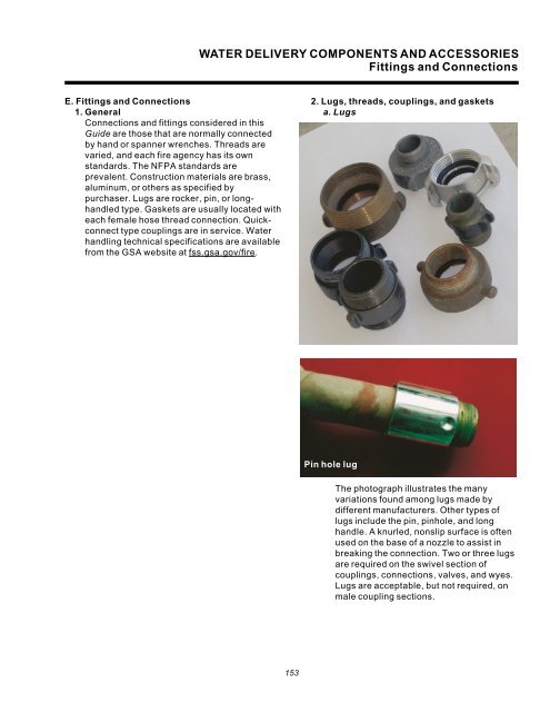
WATER DELIVERY COMPONENTS AND ACCESSORIES Fittings and Connections E. Fittings and Connections 1. General Connections and fittings considered in this Guide are those that are normally connected by hand or spanner wrenches. Threads are varied, and each fire agency has its own standards. The NFPA standards are prevalent. Construction materials are brass, aluminum, or others as specified by purchaser. Lugs are rocker, pin, or longhandled type. Gaskets are usually located with each female hose thread connection. Quickconnect type couplings are in service. Water handling technical specifications are available from the GSA website at fss.gsa.gov/fire. 2. Lugs, threads, couplings, and gaskets a. Lugs Pin hole lug The photograph illustrates the many variations found among lugs made by different manufacturers. Other types of lugs include the pin, pinhole, and long handle. A knurled, nonslip surface is often used on the base of a nozzle to assist in breaking the connection. Two or three lugs are required on the swivel section of couplings, connections, valves, and wyes. Lugs are acceptable, but not required, on male coupling sections. 153
WATER DELIVERY COMPONENTS AND ACCESSORIES Fittings and Connections b. Threads Hose threads are said to be straight or parallel. A water seal is formed as the external thread lip seats against a recessed gasket in the internal thread section. In contrast, water-pipe threads are tapered and seal against themselves. “NH” is an abbreviation of American National Fire Hose Connection Screw Thread for garden, chemical, and fire protection hose. “NPSH” is the abbreviation for American National hose coupling threads; i.e., National Pipe Straight Hose couplings for threads and nipples. The tables below show the threads currently in use. Hose Thread Tables Table 4—Threads used in current Municipal/ Department of Defense practices. Nominal Threads Maximum NFPA size per male symbol (inch) inch diameter (inch) w 8 1.38 NH 1 8 1.38 NH 12 9 1.99 NH 2 8 2.52 NH 22 72 3.07 NH 3 6 3.62 NH 32 6 4.24 NH 4 4 5.01 NH Table 5—Threads currently used by many wildland fire agencies. Nominal Threads Maximum NWCG size per male symbol (inch) inch diameter (inch) w 112 1.06 GHT 1 112 1.30 NPSH 12 9 1.99 NH 2 112 2.35 NPSH 22 72 3.07 NH 4 4 5.01 NH In wildland fire service, the larger diameter threads are used primarily for suction hose couplings. The 12-inch size is by far the most common in forestry practice and is used for distribution lines. The 1-inch connection is used on most nozzle bases, on 1-inch hose, and on w-inch hard-rubber hose for reels. The tips for straight stream and fog nozzles have w inch 112 GHT thread in general forestry/wildland practice as provided in Forest Service Specification 5100-244b. The NFPA standard calls for w-inch connections to be 8 NH threads. Use of w- inch garden hose couplings are designed for low pressure, low flow (mop-up) fire service use. 154 Higbee cut. To prevent mutilation and cross threading, and to facilitate rapid coupling, fire hose connections and fittings are manufactured with the first thread cut away or blunted. This is referred to as “blunt start” or the Higbee cut.
- Page 110 and 111: WATER PUMPING EQUIPMENT Nonhighway
- Page 112 and 113: WATER PUMPING EQUIPMENT Nonhighway
- Page 114 and 115: WATER PUMPING EQUIPMENT Nonhighway
- Page 116 and 117: WATER PUMPING EQUIPMENT Nonhighway
- Page 118 and 119: WATER PUMPING EQUIPMENT Nonhighway
- Page 120 and 121: WATER PUMPING EQUIPMENT Trailer-Mou
- Page 122 and 123: WATER PUMPING EQUIPMENT Trailer-Mou
- Page 124 and 125: WATER PUMPING EQUIPMENT Plumbing G.
- Page 126 and 127: FOAM GENERATING EQUIPMENT Foam Prop
- Page 128 and 129: FOAM GENERATING EQUIPMENT Foam Prop
- Page 130 and 131: FOAM GENERATING EQUIPMENT Foam Prop
- Page 132 and 133: FOAM GENERATING EQUIPMENT Compresse
- Page 134 and 135: FOAM GENERATING EQUIPMENT Foam Nozz
- Page 136 and 137: WATER DELIVERY COMPONENTS AND ACCES
- Page 138 and 139: WATER DELIVERY COMPONENTS AND ACCES
- Page 140 and 141: WATER DELIVERY COMPONENTS AND ACCES
- Page 142 and 143: WATER DELIVERY COMPONENTS AND ACCES
- Page 144 and 145: WATER DELIVERY COMPONENTS AND ACCES
- Page 146 and 147: WATER DELIVERY COMPONENTS AND ACCES
- Page 148 and 149: WATER DELIVERY COMPONENTS AND ACCES
- Page 150 and 151: WATER DELIVERY COMPONENTS AND ACCES
- Page 152 and 153: WATER DELIVERY COMPONENTS AND ACCES
- Page 154 and 155: WATER DELIVERY COMPONENTS AND ACCES
- Page 156 and 157: WATER DELIVERY COMPONENTS AND ACCES
- Page 158 and 159: WATER DELIVERY COMPONENTS AND ACCES
- Page 162 and 163: WATER DELIVERY COMPONENTS AND ACCES
- Page 164 and 165: WATER DELIVERY COMPONENTS AND ACCES
- Page 166 and 167: WATER DELIVERY COMPONENTS AND ACCES
- Page 168 and 169: WATER DELIVERY COMPONENTS AND ACCES
- Page 170 and 171: WATER DELIVERY COMPONENTS AND ACCES
- Page 172 and 173: WATER DELIVERY COMPONENTS AND ACCES
- Page 174 and 175: WATER DELIVERY COMPONENTS AND ACCES
- Page 176 and 177: WATER DELIVERY COMPONENTS AND ACCES
- Page 178 and 179: WATER DELIVERY COMPONENTS AND ACCES
- Page 180 and 181: WATER DELIVERY COMPONENTS AND ACCES
- Page 182: WATER DELIVERY COMPONENTS AND ACCES
- Page 186: APPENDIXES A—Nozzle Flow Rates Fl
- Page 190 and 191: APPENDIXES B—Pressure and Flow Ra
- Page 192 and 193: APPENDIXES B—Pressure and Flow Ra
- Page 194 and 195: APPENDIXES B—Pressure and Flow Ra
- Page 196 and 197: APPENDIXES B—Pressure and Flow Ra
- Page 198: APPENDIX C
- Page 201 and 202: APPENDIXES C—Flow Determination,
- Page 203 and 204: APPENDIXES C—Flow Determination,
- Page 206: APPENDIX D
- Page 209 and 210: APPENDIXES D—Service Test for Fir
WATER DELIVERY COMPONENTS AND ACCESSORIES<br />
Fittings and Connections<br />
E. Fittings and Connections<br />
1. General<br />
Connections and fittings considered in this<br />
<strong>Guide</strong> are those that are normally connected<br />
by hand or spanner wrenches. Threads are<br />
varied, and each fire agency has its own<br />
standards. The NFPA standards are<br />
prevalent. Construction materials are brass,<br />
aluminum, or others as specified by<br />
purchaser. Lugs are rocker, pin, or longhandled<br />
type. Gaskets are usually located with<br />
each female hose thread connection. Quickconnect<br />
type couplings are in service. <strong>Water</strong><br />
handling technical specifications are available<br />
from the GSA website at fss.gsa.gov/fire.<br />
2. Lugs, threads, couplings, and gaskets<br />
a. Lugs<br />
Pin hole lug<br />
The photograph illustrates the many<br />
variations found among lugs made by<br />
different manufacturers. Other types of<br />
lugs include the pin, pinhole, and long<br />
handle. A knurled, nonslip surface is often<br />
used on the base of a nozzle to assist in<br />
breaking the connection. Two or three lugs<br />
are required on the swivel section of<br />
couplings, connections, valves, and wyes.<br />
Lugs are acceptable, but not required, on<br />
male coupling sections.<br />
153


