2.1 Ultrafast solid-state lasers - ETH - the Keller Group
2.1 Ultrafast solid-state lasers - ETH - the Keller Group
2.1 Ultrafast solid-state lasers - ETH - the Keller Group

Create successful ePaper yourself
Turn your PDF publications into a flip-book with our unique Google optimized e-Paper software.
126 <strong>2.1</strong>.8 Carrier envelope offset (CEO) [Ref. p. 134<br />
<strong>2.1</strong>.8 Carrier envelope offset (CEO)<br />
Progress in ultrashort pulse generation [99Ste] has reached a level where <strong>the</strong> slowly-varyingenvelope<br />
approximation starts to fail. Pulse durations of Ti:sapphire laser oscillators have reached<br />
around 5 fs which is so short that only about two optical cycles of <strong>the</strong> underlying electric field<br />
fit into <strong>the</strong> full-width half maximum of <strong>the</strong> pulse envelope. For such short pulses <strong>the</strong> maximum<br />
electric-field strength depends strongly on <strong>the</strong> exact position of <strong>the</strong> electric field with regards to <strong>the</strong><br />
pulse envelope, i.e. <strong>the</strong> Carrier Envelope Offset (CEO) [99Tel]. In passively mode-locked <strong>lasers</strong> this<br />
carrier envelope offset is a freely varying parameter because <strong>the</strong> steady-<strong>state</strong> boundary condition<br />
only requires that <strong>the</strong> pulse envelope is <strong>the</strong> same after one round trip (Fig. <strong>2.1</strong>.19). Therefore <strong>the</strong><br />
CEO phase may exhibit large fluctuations, even when all o<strong>the</strong>r laser parameters are stabilized. We<br />
have discussed <strong>the</strong> physical origin of <strong>the</strong>se fluctuations before [02Hel2, 02Hel1]. Because nonlinear<br />
laser–matter interaction depends strongly on <strong>the</strong> strength of <strong>the</strong> electric field, this CEO fluctuations<br />
cause strong signal fluctuations in nonlinear experiments such as high-harmonic generation<br />
[00Bra], attosecond pulse generation [01Dre], photoelectron emission [01Pau1] etc.<br />
T R<br />
Electric field E<br />
Time t<br />
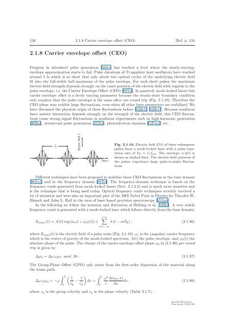
Fig. <strong>2.1</strong>.19. Electric field E(t) of three subsequent<br />
pulses from a mode-locked laser with a pulse repetition<br />
rate of T R =1/f rep. The envelope ±A(t) is<br />
shown as dashed lines. The electric-field patterns of<br />
<strong>the</strong> pulses experience large pulse-to-pulse fluctuations.<br />
Different techniques have been proposed to stabilize <strong>the</strong>se CEO fluctuations in <strong>the</strong> time domain<br />
[96Xu1] and in <strong>the</strong> frequency domain [99Tel]. The frequency-domain technique is based on <strong>the</strong><br />
frequency comb generated from mode-locked <strong>lasers</strong> (Sect. <strong>2.1</strong>.2.2) and is much more sensitive and<br />
is <strong>the</strong> technique that is being used today. Optical frequency comb techniques recently received a<br />
lot of attention and were also an important part of <strong>the</strong> 2005 Nobel Prize in Physics for Theodor W.<br />
Hänsch and John L. Hall in <strong>the</strong> area of laser-based precision spectroscopy [05Nob].<br />
In <strong>the</strong> following we follow <strong>the</strong> notation and derivation of Helbing et al. [03Hel]. A very stable<br />
frequency comb is generated with a mode-locked laser which follows directly from <strong>the</strong> time domain:<br />
E train (t) =A (t)exp(iω c t +iϕ 0 (t)) ⊗<br />
+∞∑<br />
m=−∞<br />
δ (t − mT R ) , (<strong>2.1</strong>.96)<br />
where E train (t) is <strong>the</strong> electric field of a pulse train (Fig. <strong>2.1</strong>.19), ω c is <strong>the</strong> (angular) carrier frequency<br />
whichis<strong>the</strong>centerofgravityof<strong>the</strong>mode-lockedspectrum,A(t) <strong>the</strong> pulse envelope, and ϕ 0 (t) <strong>the</strong><br />
absolute phase of <strong>the</strong> pulse. The change of <strong>the</strong> carrier-envelope offset phase ϕ 0 in (<strong>2.1</strong>.96) per round<br />
trip is given by:<br />
Δϕ 0 =Δϕ GPO mod 2π . (<strong>2.1</strong>.97)<br />
The <strong>Group</strong>-Phase Offset (GPO) only arises from <strong>the</strong> first-order dispersion of <strong>the</strong> material along<br />
<strong>the</strong> beam path:<br />
Δϕ GPO = −ω<br />
∫ L<br />
0<br />
( 1<br />
− 1 ) ∫ L<br />
ω 2<br />
dx =<br />
v g v p 0 c<br />
dn(ω, x)<br />
dx , (<strong>2.1</strong>.98)<br />
dω<br />
where v g is <strong>the</strong> group velocity and v p is <strong>the</strong> phase velocity (Table <strong>2.1</strong>.7).<br />
Landolt-Börnstein<br />
New Series VIII/1B1