FTC7220 & FTA Quick Installation Guide Objective: This ... - Ferrotec
FTC7220 & FTA Quick Installation Guide Objective: This ... - Ferrotec
FTC7220 & FTA Quick Installation Guide Objective: This ... - Ferrotec

Create successful ePaper yourself
Turn your PDF publications into a flip-book with our unique Google optimized e-Paper software.
<strong>FTC7220</strong> & <strong>FTA</strong> <strong>Quick</strong> <strong>Installation</strong> <strong>Guide</strong><br />
<strong>Objective</strong>:<br />
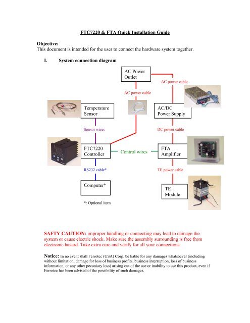
<strong>This</strong> document is intended for the user to connect the hardware system together.<br />
I. System connection diagram<br />
Temperature<br />
Sensor<br />
Sensor wires<br />
<strong>FTC7220</strong><br />
Controller<br />
RS232 cable*<br />
Computer*<br />
*: Optional item<br />
AC Power<br />
Outlet<br />
AC power cable<br />
Control wires<br />
AC power cable<br />
AC/DC<br />
Power Supply<br />
DC power cable<br />
<strong>FTA</strong><br />
Amplifier<br />
TE power cable<br />
TE<br />
Module<br />
SAFTY CAUTION: improper handling or connecting may lead to damage the<br />
system or cause electric shock. Make sure the assembly surrounding is free from<br />
electronic hazard. Take extra care and verify for all your connections.<br />
Notice: In no event shall <strong>Ferrotec</strong> (USA) Corp. be liable for any damages whatsoever (including<br />
without limitation, damage for loss of business profits, business interruption, loss of business<br />
information, or any other pecuniary loss) arising out of the use or inability to use this product, even if<br />
<strong>Ferrotec</strong> has been advised of the possibility of such damages.
Preparation<br />
Please make sure you have the following tools/parts/document ready<br />
1. Instruction manual<br />
2. <strong>FTC7220</strong> Controller<br />
3. <strong>FTA</strong> TE Amplifier<br />
4. TE Module Assembly<br />
5. Temperature sensor<br />
6. AD/DC power supply<br />
7. Computer/software (*optional)<br />
8. Screw drivers<br />
9. Cables<br />
a. AC power cable<br />
b. Control signal cable<br />
c. DC power cable<br />
d. TE power cable<br />
e. RS232 data cable (*optional)<br />
II. System Assembly<br />
Most of the connection required user to unscrew, plug in the wire and tighten up the screw.<br />
Make sure to use a proper screwdriver size and not to over-force when tighten the screws.<br />
Always make sure the wires are secured by the screws.<br />
1. Connect AC cable to the controller connecter #13 and #14, no polarity. Do<br />
not plug AC cable to the power outlet yet.<br />
Pic. AC power line connection<br />
2. Connect the temperature sensor to the controller<br />
For RTD three wires sensor: connect same color wires to the #6, #7;<br />
connect the other wire to the #5. Jumper should be opened (default).<br />
For Thermocouple: connect positive wire on #6, negative wire on #7.<br />
Jumper should be installed.<br />
For Thermistor (2252 Ohm@25 ): connect them to #6, #7, jumper<br />
setting does not matter.
Pic: 3-wire RTD connection Pic: 2-wire Thermistor connection<br />
3. Power up the controller, refer to the instruction manual and configure to<br />
the proper parameters. The panel should display the correct temperature.<br />
Unplug the power and continue the following steps.<br />
4. Connect signal control cable between the controller and amplifier<br />
Make sure the signal lines are matching<br />
Pic. Connect of control signal cable Pic. Control signal name defined on PCB<br />
Amp (EN) – Ctrl #1 (Enable)<br />
Amp (GND) – Ctrl #4 (GND)<br />
Amp (PWM) – Ctrl #8 (PWM)<br />
Amp (DIR) – Ctrl #9 (Heat/Cool Direction)<br />
5. Connect RS232 signal to DB9 connector (*optional)<br />
DB9-Pin#2 – Ctrl #2(TXD)
DB9-pin#3 – Ctrl #3(RXD)<br />
DB9-pin#5 – Ctrl #4(GND)<br />
6. Connect TE power cable to the TE module.<br />
Pic: RS232 DB9 connection<br />
Pic. TEC power line connection<br />
7. Connect DC power cable to the amplifier. Make sure polarity connection,<br />
wrong connection could cause amplifier damage.<br />
Pic. DC power connection<br />
III. Running the system<br />
1. Double check all connections<br />
2. Plug in the AC power cables for the controller, you should see the panel<br />
display light up and the temperature is displayed.<br />
Pic. Power up controller
3. Make sure the temperature setting is in the proper range not to damage the<br />
TE module or amplifier.<br />
4. Power up or Plug in the AC power cord of the AC/DC power supply. The<br />
controller will start commanding power flow to the TEC assembly.<br />
5. Refer to the “Instruction Manual” for temperature setting and adjustments.