Long Trains test bench Following the American growing ... - UIC
Long Trains test bench Following the American growing ... - UIC
Long Trains test bench Following the American growing ... - UIC

You also want an ePaper? Increase the reach of your titles
YUMPU automatically turns print PDFs into web optimized ePapers that Google loves.
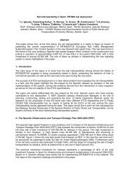
<strong>Long</strong> <strong>Trains</strong> <strong>test</strong> <strong>bench</strong><br />
<strong>Following</strong> <strong>the</strong> <strong>American</strong> <strong>growing</strong> activity around <strong>the</strong> Electronically Controlled Pneumatic Brake (<br />
ECP-Brake), in ’98 SAB-Wabco decided to start a research activity in <strong>the</strong> “long freight train”<br />
control field, especially concerning <strong>the</strong> wired communication and brake management field.<br />
<strong>Following</strong> this decision <strong>the</strong> R&D department in <strong>the</strong> Italian SAB-Wabco. S.p.a. Company begun <strong>the</strong><br />
study of <strong>the</strong> “wired” communication system and <strong>the</strong> design of a <strong>Long</strong> Train Test Bench: due to <strong>the</strong><br />
innovative research, a financing from <strong>the</strong> Italian Ministry of University and Research (MURST)<br />
was requested and subsequently obtained.<br />
At <strong>the</strong> same time, in order to participate to a bid announced by <strong>the</strong> railways DB AG and SNCF (for<br />
<strong>the</strong> realisation of a 2250m. train, built up of 125 wagons and 16 locomotives, “wire bus” and “radio<br />
bus” controlled) SAB-Wabco joined <strong>the</strong> French company ALSTOM Transport in a consortium.<br />
This consortium, named SWAT, won <strong>the</strong> bid in ’99 and <strong>the</strong> new DB-SNCF project name became<br />
FEBIS (Freight Electronic Brake Intelligent System). The FEBIS project takes today advantage of<br />
<strong>the</strong> Italian SAB Wabco Test Bench for all <strong>the</strong> investigation and validation activities necessary<br />
before <strong>the</strong> FEBIS components will be delivered to DB-SNCF for <strong>the</strong> final field installation.<br />
For detailed references about FEBIS development, please see <strong>the</strong> article “FEBIS System aspects”<br />
from S.Witte, R.Tione, C.Coulange, A.Launay presented in this session.<br />
Overview<br />
The purpose of <strong>the</strong> <strong>Long</strong> Train Test Bench LTTB is to allow <strong>the</strong> physical simulation of <strong>the</strong><br />
following subsystems:<br />
The Pneumatic Brake subsystem<br />
The Electronic subsystem<br />
The “Double Wire” Communication and Energy subsystem<br />
The Radio Communication subsystem<br />
The above subsystems are referred to a train which max. parameters will be:<br />
2250m. length<br />
125 wagon max<br />
4 locomotives<br />
Due to <strong>the</strong> necessity to estimate <strong>the</strong> differences between a <strong>UIC</strong> train and a FEBIS train, and to<br />
validate <strong>the</strong> FEBIS performances, <strong>the</strong> representativeness of <strong>the</strong> LTTB has been <strong>the</strong> major driver for<br />
<strong>the</strong> LTTB design. Moreover, due to <strong>the</strong> huge quantity of <strong>test</strong>s to be carried out in different train<br />
configuration, one of <strong>the</strong> major functional requirements for <strong>the</strong> LTTB design has been <strong>the</strong> high<br />
flexibility in re-configuration.<br />
The Pneumatic Brake subsystem<br />
The pneumatic brake subsystem takes into account <strong>the</strong> necessity to reproduce freight trains,<br />
characterised to have a Ø 1”_ brake pipe: <strong>the</strong> LTTB brake pipe has been built based on horizontal<br />
loops of stainless steel pipes Ø 1”_ for a total length of 2284m.<br />
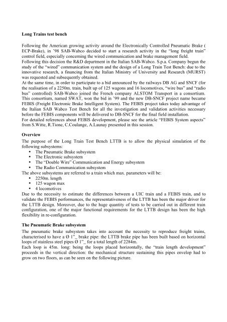
Each loop is 45m. long: being <strong>the</strong> loops placed horizontally, <strong>the</strong> “train length development”<br />
proceeds in <strong>the</strong> vertical direction: <strong>the</strong> mechanical structure sustaining this pipes envelop had to<br />
grow on two floors, as can be seen on <strong>the</strong> following picture.
<strong>Long</strong> Train Test Bench “landscape”<br />
Moreover, to allow simulation of “mixed brake pipe” trains, an additional brake pipe Ø 1” has been<br />
added in <strong>the</strong> structure for a fur<strong>the</strong>r length of 1246m, still developed with horizontal loops.<br />
Both <strong>the</strong> brake pipes loops are built of linear segments 5m. long, linked toge<strong>the</strong>r with different<br />
connection types, which function is ei<strong>the</strong>r to simulate <strong>the</strong> flexible hose inter-wagon connection,<br />
ei<strong>the</strong>r to allow <strong>the</strong> insertion of <strong>the</strong> wagons brake packages. This structure allows <strong>the</strong> creation of<br />
different wagon lengths (modulo 5m.), as well as <strong>the</strong> creation of a variety of train compositions.<br />
The brake package for each wagon is built of <strong>the</strong> following components:<br />
brake cylinder with variable stroke<br />
distributor valve with control reservoir<br />
auxiliary reservoir<br />
The following list of distributor and related components is available, for a total of 132 vehicles:<br />
n° 45 SAB WABCO type W-U<br />
n° 38 SAB WABCO type C3W<br />
n° 29 Oerlikon type ESTGP<br />
n° 4 Knorr type KE 2d SL-D<br />
n° 4 Knorr type KE 2d SL-ALB/d8<br />
n° 4 Knorr type KE 2d SL-ALD<br />
n° 4 Knorr type KE 1d SL<br />
n° 4 Knorr type KE Od KSL n 6d<br />
The following list of Driver’s Brake Valve is available :<br />
SAB-Wabco “Wabcotrol Unificato” with electronic control, developed and implemented on<br />
“Trenitalia” specifications.
SAB-Wabco “Eurotrol” with electronic control, under SNCF homologated<br />
SAB-Wabco PBL-91, SNCF standard<br />
Oerlikon FV4, Trenitalia and SBB standard on old locomotives.<br />
The Pneumatic Brake subsystem validation<br />
Normally a train <strong>test</strong> <strong>bench</strong> is used to validate brake components in <strong>the</strong> standard <strong>UIC</strong> configuration.<br />
In our case <strong>the</strong> LTTB is necessary to estimate and understand <strong>the</strong> real behaviour of a long train<br />
during <strong>the</strong> braking phase, before this train will be physically built and moved on track, with all <strong>the</strong><br />
related risks.<br />
For this reason <strong>the</strong> LTTB must be validated against real configurations in order to have a realistic<br />
return from <strong>the</strong> simulations.<br />
The DB and SNCF Railways have kindly supplied measurements done on real trains:<br />
DB 650m. brake pipe Ø 1”_<br />
SNCF 750m. brake pipe mixed configuration Ø 1” and Ø 1”_<br />
Moreover o<strong>the</strong>r two references have been used:<br />
SAB-Wabco France Train Test Bench 1200m. brake pipe Ø 1”_<br />
ERRI B 126/RP 25 curve<br />
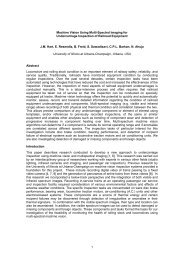
A special mention must be given to <strong>the</strong> SAB-WABCO France Train Test Bench: differently from<br />
<strong>the</strong> SAB-WABCO Italy LTTB, <strong>the</strong> French tool is built of real train component regarding flexible<br />
interconnection hoses between wagons, compliant with <strong>the</strong> Fiche <strong>UIC</strong> 541-1, annex 4.<br />
The SAB-WABCO France Train Test Bench composition respects <strong>the</strong> Fiche <strong>UIC</strong> 547, annexe 4:<br />
this fact makes this device suitable to be a good reference for <strong>the</strong> LTTB validation.<br />
The following picture shows a comparison between <strong>the</strong> DB train in Emergency brake and Service<br />
brake.<br />
LTTB – DB train comparison in Emergency
LTTB – DB train comparison in Service<br />
The time difference between <strong>the</strong> two curves (anyway acceptable) is due to <strong>the</strong> different Driver’s<br />
Brake Valves used on <strong>the</strong> different systems: The DB measurement is done using a DB locomotive,<br />
while <strong>the</strong> LTTB measurements have been done using <strong>the</strong> SNCF approved PBL-91, which is<br />
submitted to different requirements and is a little faster.<br />
The next picture shows two couples of curves: one couple is a comparison between <strong>the</strong> SAB-Wabco<br />
France TTB and <strong>the</strong> LTTB in <strong>the</strong> same configuration, <strong>the</strong> o<strong>the</strong>r coupe is <strong>the</strong> comparison between<br />
<strong>the</strong> SNCF mixed configuration train and <strong>the</strong> LTTB equal configuration.<br />
In this case <strong>the</strong> PBL-91 has been always used, and <strong>the</strong> superimposition of <strong>the</strong> curves is quite<br />
evident, so confirming <strong>the</strong> full representativness of <strong>the</strong> LTTB.
LTTB – SNCF train comparison<br />
The next picture shows <strong>the</strong> comparison between <strong>the</strong> two SAB-Wabco devices in 1200m. equal<br />
configuration and <strong>the</strong> ERRI B 126/RP 25 curve.<br />
LTTB – ERRI curve comparison<br />
No reference is today available about a train 2250m. <strong>UIC</strong> brakes equipped, at least in a<br />
configuration suitable to be compared with an equivalent SAB-Wabco Italy LTTB.
SNCF kindly supplied measurements about such a long train, but <strong>the</strong> composition was mixed Ø 1”<br />
and Ø 1”_, in a unknown wagon configuration, so it was impossible to accurately reproduce <strong>the</strong> real<br />
case.<br />
The Data Acquisition System<br />
The LTTB has been equipped with a Data Acquisition System DAS able to monitor and collect<br />
pressure data during <strong>the</strong> simulations, developed and realised by SAB-Wabco.<br />
The hardware characteristics of <strong>the</strong> DAS are:<br />
200 pressure transducers installed on 50 wagons out of 132; <strong>the</strong> wagons are monitored in<br />
four different points: <strong>the</strong> brake pipe, <strong>the</strong> auxiliary reservoir, <strong>the</strong> control reservoir , <strong>the</strong> brake<br />
cylinder.<br />
<strong>the</strong> pressure transducer precision is within ±1%<strong>the</strong> full range. An embedded calibration<br />
process increases this precision<br />
<strong>the</strong> sampling rate of <strong>the</strong> DAS is programmable up to 200Hz (5ms. acquisition period)<br />
all <strong>the</strong> 200 transducers are acquired in less than 1ms. in order to have a negligible “time<br />
skew” with respect <strong>the</strong> maximum sampling rate<br />
The software characteristics of <strong>the</strong> DAS are:<br />
recording and saving capabilities<br />
replay, rewind and fast-forward functions<br />
cursor are available during <strong>the</strong> replay function, for detailed measurements<br />
Two kind of visualisations are available on <strong>the</strong> screen:<br />
visualisation versus time<br />
visualisation versus train length.<br />
While <strong>the</strong> visualisation versus time is useful to verify <strong>the</strong> time dependence between different inputs,<br />
<strong>the</strong> visualisation versus train length becomes relevant to observe and compare <strong>the</strong> different<br />
pneumatic behaviour of <strong>the</strong> long train when in <strong>UIC</strong> mode and when in FEBIS mode.<br />
The next picture shows an example of visualisation versus time, where two pressure transducers<br />
waveforms are shown: in particular, <strong>the</strong> two pressure transducers are located on <strong>the</strong> Brake Pipe,<br />
2153m. distant one each o<strong>the</strong>r, and <strong>the</strong> acquisition is performed during <strong>the</strong> propagation of <strong>the</strong><br />
accelerating chambers wave. The period between <strong>the</strong> two falling edges is 7.52s and evidences a<br />
wave propagation speed of 286m/s.
Accelerating chambers wave propagation<br />
The next picture shows an example of visualisation versus train length, where <strong>the</strong> four Pneumatic<br />
Brake subsystem magnitudes are shown:<br />
brake pipe (blue)<br />
auxiliary reservoir (red)<br />
control chamber (yellow)<br />
cylinder (green)<br />
The picture has been captured during a brake application in conventional <strong>UIC</strong> mode, 25s after <strong>the</strong><br />
brake application start (distributors in P mode).
<strong>UIC</strong> brake application after 25s<br />
The Electronic and Communication Subsystem<br />
The FEBIS Wired Communication system is based on <strong>the</strong> redundant Power Line concept. To be<br />
able to properly simulate <strong>the</strong> reality, <strong>the</strong> double Power Line has been fully reproduced: horizontal<br />
loops, made with <strong>the</strong> same type of cable used on <strong>the</strong> real train (shielded AWG8 cable with 50<br />
characteristic impedance), have been placed in a receptacle running on <strong>the</strong> top of <strong>the</strong> LTTB<br />
structure, in segments of 18m each, for a total length of 2500m per Power Line. Spare segments of<br />
4m. each are available to create a huge variety of wagon lengths. Resistive series loads can be<br />
inserted along <strong>the</strong> two Power Lines development in order to simulate exceptional voltage drops.<br />
Obviously <strong>the</strong> two Power Lines can be added in series to measure <strong>the</strong> physical limits of <strong>the</strong><br />
communication channel.<br />
Per each wagon two electronic Junction Boxes derivate <strong>the</strong> two Power Lines to <strong>the</strong> wagon<br />
electronic equipment: a total of 132 Local Control Units LCU’s (this is <strong>the</strong> name of <strong>the</strong> wagon<br />
electronic equipment in <strong>the</strong> FEBIS terminology) are available on <strong>the</strong> LTTB. The electronic devices<br />
are hosted is racks placed around <strong>the</strong> LTTB, available for <strong>the</strong> developers investigations.
LCU’s installed on <strong>the</strong> LTTB<br />
The two Power Lines are fed by a DC/DC static converter, delivering <strong>the</strong> 48Vdc and 230Vdc<br />
requested by <strong>the</strong> system.<br />
Finally, a Master Control Unit MCU (this is <strong>the</strong> name of <strong>the</strong> Locomotive electronic equipment in<br />
<strong>the</strong> FEBIS terminology) has <strong>the</strong> complete control of <strong>the</strong> system.<br />
A driver console allows <strong>the</strong> interface of <strong>the</strong> LTTB with <strong>the</strong> driver.<br />
Concerning <strong>the</strong> Radio Communication channel, <strong>the</strong> LCU’s, as well as <strong>the</strong> MCU, will be equipped<br />
with a 5.8GHz DSSS modem.<br />
The LTTB is not provided of <strong>the</strong> axle generators, as <strong>the</strong>se components are not directly involved in<br />
<strong>the</strong> communication system.
Train dynamics simulation<br />
One of <strong>the</strong> LTTB additional advantages is to produce reliable “real” data which can be used for<br />
fur<strong>the</strong>r numerical analysis.<br />
In order to estimate <strong>the</strong> benefits brought by <strong>the</strong> FEBIS system in <strong>the</strong> “<strong>Long</strong> <strong>Trains</strong>” management,<br />
<strong>the</strong> LTTB output data are used as input to train dynamics simulation tools.<br />
While <strong>the</strong> author is writing, a research co-operation running between SAB-Wabco Italy, <strong>the</strong> Turin<br />
“Politecnico” and <strong>the</strong> Rome University “Tor Vergata”, with <strong>the</strong> purpose to develop a Train<br />
dynamics simulator which simulation level will include:<br />
rail altimetrical profile<br />
rail planimetric profile, in o<strong>the</strong>r words corners effect<br />
wagons weight and different center of gravity position<br />
wagons buffer to buffer reaction and geometry (not axial contact)<br />
wagons suspensions reactions<br />
rail to wheels reaction<br />
friction material<br />
In this moment he LTTB is equipped of a software “real time” train dynamics simulator, based on a<br />
limited ma<strong>the</strong>matical model.<br />
The model describes a train where <strong>the</strong> mechanical links between wagons are assumed stiff: in o<strong>the</strong>r<br />
words a heavy simplification has been done not taking in account <strong>the</strong> elastic “buffer to buffer”<br />
various effects, nei<strong>the</strong>r taking in account <strong>the</strong> suspensions interactions.<br />
This simulator anyway uses <strong>the</strong> altimetric profile applied on each wagon of <strong>the</strong> train consist;<br />
moreover <strong>the</strong> shoes friction coefficient ( versus speed) is taken in account, as well as <strong>the</strong> railwheel<br />
friction coefficient versus speed and versus planimetric profile.<br />
Even if not at <strong>the</strong> level of <strong>the</strong> today’s most sophisticated simulators (e.g. E-Train), this one already<br />
well helps giving preliminary train behaviours evaluations, waiting for <strong>the</strong> final one most advanced<br />
developed with <strong>the</strong> Italian Universities.<br />
Conclusions<br />
The SAB-Wabco <strong>Long</strong> Train Test Bench represents today <strong>the</strong> European reference for <strong>the</strong> future<br />
<strong>Long</strong> Freight <strong>Trains</strong> electronically controlled.<br />
While <strong>the</strong> author is writing this article, <strong>the</strong> first FEBIS <strong>test</strong>s have been started on <strong>the</strong> complete<br />
system: relevant results of this research will be available and shown during <strong>the</strong> WCRR presentation.<br />
Just for completion a full FEBIS brake application on 2250m has been recorded and <strong>the</strong> result is<br />
shown in <strong>the</strong> following picture.<br />
The picture has been captured 2s after <strong>the</strong> brake command delivery from <strong>the</strong> MCU (FEBIS Brake<br />
slope in P mode): it is interesting <strong>the</strong> comparison whit <strong>the</strong> picture “<strong>UIC</strong> brake application after<br />
25s” previously shown.<br />
It is evident <strong>the</strong> difference between <strong>the</strong> <strong>UIC</strong> mode and <strong>the</strong> FEBIS mode, in term of time delay of<br />
application as well as in term of uniformity of brake effort applied along <strong>the</strong> train.<br />
***FEBIS Brake application after 2s.***