A New Architecture of Wireless Mesh Networks Based IEEE 802.11s ...
A New Architecture of Wireless Mesh Networks Based IEEE 802.11s ...
A New Architecture of Wireless Mesh Networks Based IEEE 802.11s ...

Create successful ePaper yourself
Turn your PDF publications into a flip-book with our unique Google optimized e-Paper software.
This full text paper was peer reviewed at the direction <strong>of</strong> <strong>IEEE</strong> Communications Society subject matter experts for publication in the <strong>IEEE</strong> ICC 2011 proceedings<br />
A new architecture <strong>of</strong> wireless mesh networks<br />
based <strong>IEEE</strong> <strong>802.11s</strong> directional antennas<br />
Jalel Ben-Othman<br />
Laboratoire CNRS-Prism<br />
University <strong>of</strong> Versailles<br />
jbo@prism.uvsq.fr<br />
Lynda Mokdad<br />
Laboratoire LACL<br />
University <strong>of</strong> Paris 12<br />
Lynda.mokdad@univ-paris12.fr<br />
Abstract—This paper tackle the problem <strong>of</strong> coverage in <strong>IEEE</strong><br />
802.11 using mesh mode. Instead <strong>of</strong> omnidirectional coverage,<br />
we propose to use directional coverage. The use <strong>of</strong> directional<br />
antenna have two main advantages. The first is to increase the<br />
performance <strong>of</strong> QoS <strong>of</strong> considered services. The second is that<br />
using directional antenna allows to improve the spatial reuse<br />
<strong>of</strong> the wireless channel, which allows nodes to communicate<br />
simultaneously without interference, and potentially establish<br />
links between nodes far away from each other, and the number <strong>of</strong><br />
routing hops can be fewer than that <strong>of</strong> omnidirectional antennas.<br />
We also propose an new amendment to reduce the routing<br />
overhead related to the use <strong>of</strong> multiple interfaces. We have<br />
evaluated the performance <strong>of</strong> the proposed architecture and we<br />
show with numerical results that the use <strong>of</strong> directional coverage<br />
outperform the omnidirectional coverage.<br />
I. INTRODUCTION<br />
Today <strong>IEEE</strong> 802.11 is the most widely used standard in<br />
WLAN. Since the first deployment several amendments have<br />
been developed to adapt this standard for different use as the<br />
<strong>IEEE</strong> <strong>802.11s</strong> for mesh networks. The <strong>Wireless</strong> <strong>Mesh</strong> <strong>Networks</strong><br />
(WMN) are designed to communicate between nodes<br />
using the air interface organized in mesh topology. In this<br />
network the <strong>Mesh</strong> Point (MP) nodes communicate directly<br />
by the meduim <strong>of</strong> transmission radio with their neighbors<br />
through a multihop routing protocol. The extension <strong>of</strong> <strong>IEEE</strong><br />
802.11 MAC standard has been done by defining new wireless<br />
configuration that manage the topology, the quality <strong>of</strong> radio<br />
link and the routing protocols to increase the effective coverage<br />
area. In this Draft, the DS <strong>of</strong> an AP can be replaced with<br />
wireless links or multi-hop paths between multiple APs.<br />
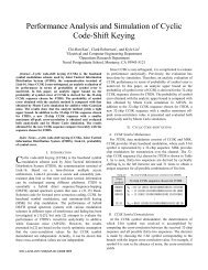
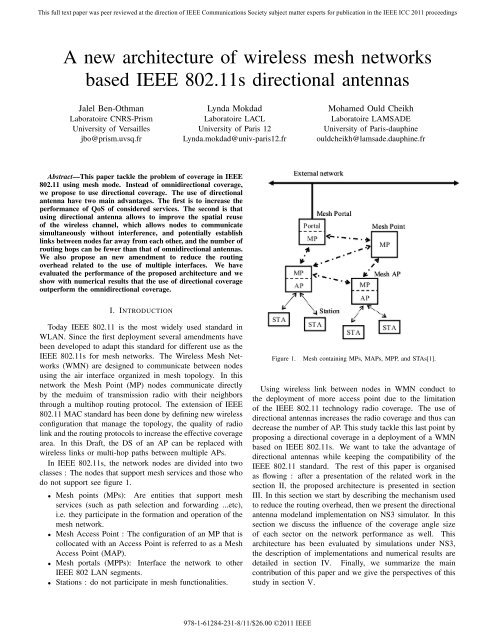
In <strong>IEEE</strong> <strong>802.11s</strong>, the network nodes are divided into two<br />
classes : The nodes that support mesh services and those who<br />
do not support see figure 1.<br />
• <strong>Mesh</strong> points (MPs): Are entities that support mesh<br />
services (such as path selection and forwarding ...etc),<br />
i.e. they participate in the formation and operation <strong>of</strong> the<br />
mesh network.<br />
• <strong>Mesh</strong> Access Point : The configuration <strong>of</strong> an MP that is<br />
collocated with an Access Point is referred to as a <strong>Mesh</strong><br />
Access Point (MAP).<br />
• <strong>Mesh</strong> portals (MPPs): Interface the network to other<br />
<strong>IEEE</strong> 802 LAN segments.<br />
• Stations : do not participate in mesh functionalities.<br />
978-1-61284-231-8/11/$26.00 ©2011 <strong>IEEE</strong><br />
Mohamed Ould Cheikh<br />
Laboratoire LAMSADE<br />
University <strong>of</strong> Paris-dauphine<br />
ouldcheikh@lamsade.dauphine.fr<br />
Figure 1. <strong>Mesh</strong> containing MPs, MAPs, MPP, and STAs[1].<br />
Using wireless link between nodes in WMN conduct to<br />
the deployment <strong>of</strong> more access point due to the limitation<br />
<strong>of</strong> the <strong>IEEE</strong> 802.11 technology radio coverage. The use <strong>of</strong><br />
directional antennas increases the radio coverage and thus can<br />
decrease the number <strong>of</strong> AP. This study tackle this last point by<br />
proposing a directional coverage in a deployment <strong>of</strong> a WMN<br />
based on <strong>IEEE</strong> <strong>802.11s</strong>. We want to take the advantage <strong>of</strong><br />
directional antennas while keeping the compatibility <strong>of</strong> the<br />
<strong>IEEE</strong> 802.11 standard. The rest <strong>of</strong> this paper is organised<br />
as flowing : after a presentation <strong>of</strong> the related work in the<br />
section II, the proposed architecture is presented in section<br />
III. In this section we start by describing the mechanism used<br />
to reduce the routing overhead, then we present the directional<br />
antenna modeland implementation on NS3 simulator. In this<br />
section we discuss the influence <strong>of</strong> the coverage angle size<br />
<strong>of</strong> each sector on the network performance as well. This<br />
architecture has been evaluated by simulations under NS3,<br />
the description <strong>of</strong> implementations and numerical results are<br />
detailed in section IV. Finally, we summarize the main<br />
contribution <strong>of</strong> this paper and we give the perspectives <strong>of</strong> this<br />
study in section V.
This full text paper was peer reviewed at the direction <strong>of</strong> <strong>IEEE</strong> Communications Society subject matter experts for publication in the <strong>IEEE</strong> ICC 2011 proceedings<br />
II. RELATED WORK<br />
Directionnal Antennas (DA) have received increasing interest<br />
in recent years, especially in the context <strong>of</strong> an ad hoc<br />
network, due to their better performance. By using DA in<br />
<strong>IEEE</strong> <strong>802.11s</strong> backbone, the nodes can communicate simultaneously<br />
without interference, and potentially establish links<br />
between nodes far away from each other, and the number <strong>of</strong><br />
routing hops can be fewer. However, the existing <strong>IEEE</strong> 802.11<br />
(mesh) standards does not gain with the implementation <strong>of</strong> DA<br />
and poses additional technical challenges such as deafness<br />
and hidden- and exposed terminal problems arisen due to<br />
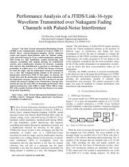
directional transmissions[5]. Deafness is caused when a node,<br />
C, attempts to initiate dialog with a node, A, while A is<br />
engaged in communication with another node [6], as shown<br />
in figure 2.<br />
Figure 2. A scenario illustrating the problem <strong>of</strong> deafness [6].<br />
Most work on directional antennas (they are <strong>of</strong>ten in the<br />
context <strong>of</strong> ad hoc network) propose to change the MAC<br />
layer, to take advantage <strong>of</strong> these benefits and to solve the<br />
deafness and hidden- and exposed terminal problems. In<br />
DMAC (Directionnal MAC) [7] all frames are transmitted<br />
directionally except for the CTS (Clear To Send). In MMAC<br />
(Multi-hop RTS MAC) [7] the authors proposes the multi-hop<br />
RTS (Request To Send) to take advantage <strong>of</strong> the higher gain<br />
obtained by directional antennas. In [6], the authors propose<br />
ToneDMAC to solve the problem <strong>of</strong> deafness. However, most<br />
<strong>of</strong> these works are not compatible with the 802.11 standard<br />
(problem <strong>of</strong> the interoperability and evolution). To the best <strong>of</strong><br />
our knowledge no work has been done on using directional<br />
antenas in <strong>IEEE</strong> <strong>802.11s</strong>.<br />
In this paper, we propose a new deployment <strong>of</strong> <strong>IEEE</strong><br />
<strong>802.11s</strong> that take the advantage <strong>of</strong> directional antennas while<br />
keeping the compatibility <strong>of</strong> the <strong>IEEE</strong> <strong>802.11s</strong>tandard.<br />
III. OUR PROPOSAL<br />
In our proposal, we use a sectorial antenna, which consists<br />
<strong>of</strong> multiple fixed beam antennas aimed in different directions,<br />
each covering a different sector <strong>of</strong> space, all <strong>of</strong> them together<br />
giving full 2π coverage. A fixed beam antenna is the traditional<br />
directional antenna which is pre-fixed in particular<br />
direction ( has a fixed gain pr<strong>of</strong>ile with a primary lobe pointing<br />
in a single direction). Steering the beam is only possible by<br />
physically changing the orientation <strong>of</strong> the antenna[10]. Using<br />
this configuration allows to solve the deafness problem.<br />
The main purpose <strong>of</strong> our proposal is to take the advantage<br />
<strong>of</strong> directional antennas while keeping the compatibility <strong>of</strong> the<br />
<strong>IEEE</strong> 802.11 MAC and to reduce the routing overhead. In the<br />
flowing we describe the mechanism that we propose to reduce<br />
the routing overhead, then we present the directionnal antenna<br />
model and their implementation in NS3 simulator that we use<br />
for the simulations.<br />
A. Sector-HWMP<br />
The mechanism defined in the following is valid for the two<br />
modes (Proactive tree building mode and On demand mode).<br />
In this mechanism, if a source MP A needs to find a path to<br />
a destination MP B :<br />
• if node A knows the position <strong>of</strong> node B, the PREQ is<br />
transmitted only by the fixed beam antenna that the MP<br />
B is inside <strong>of</strong> their three-dimensional radiation beam.<br />
• Otherwise, the PREQ is broadcasted by all beam antennas.<br />
In our proposal, each node has a table where it keeps the<br />
list <strong>of</strong> others nodes positions. The PREQ and PREP messages<br />
format are modified to carry the sender potision. Before an<br />
MP sends PREQ or reply with PREP , it puts its potision.<br />
When an MP receives a PREQ or PREP, it updates its<br />
positions table by adding the new entries ( new positions, if<br />
exists).<br />
The PREQ element is used for discovering a path to one<br />
or more destinations. Whenever an MP have to send or have<br />
to forward a PREQ to a set <strong>of</strong> destinations, it checks if it<br />
exists an entry in the positions table for each destination. The<br />
PREQ which will be sent by the interface i must contain<br />
only the subset <strong>of</strong> destinations address <strong>of</strong> the MPs that are<br />
inside <strong>of</strong> their three-dimensional radiation beam. By this way<br />
we reduce the overhead : Some interfaces my have a subset<br />
empty (No PREQ have to send on these interfaces or the<br />
size <strong>of</strong> PREQ is reduced) and the number <strong>of</strong> intermediates<br />
MP are reduced. To determines if a MP destination is inside<br />
<strong>of</strong> the three-dimensional radiation beam <strong>of</strong> the beam antenna<br />
<strong>of</strong> the interface i, the MP uses the algorithm described in<br />
[9]. The subset <strong>of</strong> destinations address that not exist in<br />
positions table <strong>of</strong> the MP (Sender, intermediate ) will be<br />
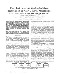
set in each preq broadcasted(see figure 3). When three<br />
consecutive attempts fail at path discovery towards a given
This full text paper was peer reviewed at the direction <strong>of</strong> <strong>IEEE</strong> Communications Society subject matter experts for publication in the <strong>IEEE</strong> ICC 2011 proceedings<br />
(set <strong>of</strong>) destination(s), this subset <strong>of</strong> destinations address will<br />
be set in each broadcasted preq.<br />
Figure 3. Figure illustrating Sctor-HWMP.<br />
In Figure 3, we assume that the source MP has three fixed<br />
beam antennas aimed in different directions, each covering an<br />
angle <strong>of</strong> 120 degrees. In this figure, if a MP source knows the<br />
position <strong>of</strong> the MP destination then, the destination address<br />
<strong>of</strong> this MP will be set only in the PREQ copy that must be<br />
transmited the antenna 1. Otherwise, this address must be<br />
added in all PREQ broadcasted by 1,2 and 3.<br />
1) sectorization issues : In this section we discuss the<br />
influence <strong>of</strong> the coverage angle size <strong>of</strong> each sector on the<br />
network performance.<br />
Figure 4. Figure illustrating sectorization issues on the network performance.<br />
B. Directionnal antenna model<br />
A directional antenna is defined as: ”having the property <strong>of</strong><br />
radiating or receiving electromagnetic waves more effectively<br />
in some directions than in others” [3]. In practice, when one<br />
wants to describe how a particular antenna works, some basic<br />
characteristics common to all types <strong>of</strong> antennas, are given:<br />
Impedance, radiation pattern, Polarization and Gain.<br />
In wireless network simulations, we are interested only<br />
to determines when and with what reception power a signal<br />
arrives at a receiver. The signal strength is used to determine<br />
whether the frame is transmitted successfully. There is several<br />
propagation models to predict the power received signal (Free<br />
Space, Two Ray Ground, Shadowing,....etc ).<br />
Free Space model is used to simulate path loss <strong>of</strong> wireless<br />
communication when line-<strong>of</strong>-sight path exists between transmitter<br />
and receiver. Two Ray Ground model is used when<br />
line-<strong>of</strong>-sight path exists and reflection <strong>of</strong> ground is considered.<br />
Shadowing model simulates shadow effect <strong>of</strong> obstructions<br />
between the transmitter and receiver.<br />
For example, the free-space attenuation can be computed<br />
using Friis modernized equation :<br />
where :<br />
PRx = PTx∗GRx∗GTx∗λ2<br />
(4∗π∗d) 2 ∗L<br />
• PRx,PTx are reception and transmission power in watt;<br />
• GRx,GTx are reception and transmission gain;<br />
• L is a general dimensionless system loss coefficient;<br />
• λ is the wavelength;<br />
• and d is the distance in meters between sender and<br />
receiver.<br />
Most <strong>of</strong> the current implementations <strong>of</strong> the <strong>IEEE</strong> 802.11<br />
physical models (802.11a/b/g...etc.) in a packet-based network<br />
simulators uses only omnidirectional antennas models (<br />
GRx =1and GTx =1). These implementations use an object<br />
(wifichannel in NS3, <strong>Wireless</strong>Channel in NS2) to models the<br />
radio signal transmission. This object keeps a list <strong>of</strong> all nodes<br />
, or the list <strong>of</strong> their physical components on this channel ( all<br />
the nodes participate in the simulation). It works just like a<br />
physical media : receives packets from nodes and assigns them<br />
to all possible destination and following the reception power,<br />
the receiving node decides whether the packet is correct or<br />
not.<br />
In directional antenna models, the electromagnetic waves<br />
is mainly radiated in some directions and consequently the<br />
reception and transmission gains are calculated differently.<br />
Also, the received packets by the wifichannel object do not<br />
assigned to all nodes in the simulation but only to the receivers<br />
inside the three-dimensional radiation beam.<br />
The gain <strong>of</strong> an antenna (in a given direction) is defined as<br />
”the ratio <strong>of</strong> the intensity, in a given direction, to the radiation<br />
intensity that would be obtained if the power accepted by the<br />
antenna were radiated isotropically (the power accepted (input)<br />
by the antenna divided by 4π)” [4].<br />
Gain =4π U(θ,φ)<br />
Pin<br />
Since all <strong>of</strong> the accepted (input) power is not radiated<br />
(because <strong>of</strong> losses),the total radiated power (Prad) is related<br />
to the total input power (Pin )by:<br />
Prad = ecdPin<br />
where ecd, is the radiation efficiency <strong>of</strong> the antenna.<br />
Gain = ecd[4π U(θ,φ)<br />
Prad ]<br />
The maximum value <strong>of</strong> the gain can be expressed according<br />
to the beam solid angle :<br />
U(θ, φ) =B0F (θ, φ)<br />
Prad = ◦ ��<br />
Ω<br />
Gainmax = ecd<br />
U(θ, φ)dΩ =B0<br />
Gainmax = ecd 4π<br />
ΩA<br />
� 2π<br />
0<br />
� π<br />
F (θ, φ)sinθdθdφ<br />
0<br />
� 4π<br />
2π � π<br />
[ F (θ,φ)sinθdθdφ]/F (θ,φ)|max<br />
0 0
This full text paper was peer reviewed at the direction <strong>of</strong> <strong>IEEE</strong> Communications Society subject matter experts for publication in the <strong>IEEE</strong> ICC 2011 proceedings<br />
Table I<br />
SIMULATION PARAMETERS<br />
Parameters Value<br />
CBR (DataRate (Mb/s)) 1<br />
CBR (PacketSize ) 1000<br />
MPEG 4 based on a stream trace file (See [11,12])<br />
PHY OFDM 5 GHz<br />
Channel 20MHz<br />
txPower 16.0206 dBm<br />
txGain 6.0206 dB<br />
rxGain 6.0206 dBm<br />
EnergyDetectionThreshold -96.0 dBm<br />
propagation loss model log-distance<br />
DataMode wifia-6mbs<br />
Simulation time 250 (seconds)<br />
Number <strong>of</strong> nodes 25<br />
Where ΩA is the beam solid angle.<br />
For our simulations, we consider an antenna formed by a<br />
cone (The beam width <strong>of</strong> this antenna is 2ϕ and ecd =1) with<br />
spherical cap model , which is a mathematical approximation<br />
for simplicity, the solid angle :<br />
ΩA =2π(1 − cos ϕ)<br />
The gain can be expressed as :<br />
4π<br />
GRx = GTx = ecd[<br />
2π(1−cos ϕ) ]<br />
2<br />
GRx = GTx =[ (1−cos ϕ) ]<br />
To check if a receiver is inside the three-dimensional<br />
radiation beam <strong>of</strong> the antenna, we use the algorithms defined<br />
in [9].<br />
The figure 5 shows an UML diagram illustrating directionnal<br />
antenna implementation. In this figure we show only the<br />
part <strong>of</strong> <strong>IEEE</strong> 802.11 models provided in ns-3 that we have<br />
changed.<br />
IV. SIMULATION RESULTS<br />
We present and discuss in this section our simulation results<br />
for the performance study <strong>of</strong> our multipath routing protocol.<br />
We used NS3 for our simulations. The simulations are<br />
executed using the parameters <strong>of</strong> Table I .<br />
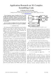
Figure 6 represents the reception power according to the<br />
distance and the antenna gain. For these simulations we used<br />
two different type <strong>of</strong> antennas. The firs is directional with<br />
120 degrees <strong>of</strong> beamwidth while the second is omnidirectional.<br />
The numerical results are based on the log propagation model.<br />
The figure shows for omnidirectional antenna the link between<br />
two nodes is efficient for a distance less than 170m. For a<br />
directional antenna the distance between two nodes is efficient<br />
up to 370 m. These results confirm that using directional<br />
antenna can improve the distance between nodes.<br />
In Figure 7 and 8 we have plotted the throughput and the<br />
end-to-end delay according to the distance respectively. The<br />
considered traffic is composed by two different sources one<br />
CBR and a multimedia traffic. We can notice from the both<br />
figures that better performances are for a distance less than<br />
220m.<br />
Figure 6. Directional Vs Omnidirectional antenna<br />
Figure 7. global throughput<br />
Figure 8. PDR<br />
V. CONCLUSION<br />
<strong>IEEE</strong> <strong>802.11s</strong> is the amendment <strong>of</strong> <strong>IEEE</strong> 802.11 that enable<br />
the mesh mode. The current deployment is made using<br />
omnidirectional antenna. Recently, the directional antenna<br />
has received intensive research due to its variety <strong>of</strong> potential
This full text paper was peer reviewed at the direction <strong>of</strong> <strong>IEEE</strong> Communications Society subject matter experts for publication in the <strong>IEEE</strong> ICC 2011 proceedings<br />
��������������������<br />
������<br />
������<br />
������������������<br />
������������������<br />
���������������<br />
���������������������������������������������������������������������������������������������������������������������������������������������������<br />
��������<br />
�������<br />
������������������������������������������������������������������������������������������������������<br />
������������������������������������������<br />
��������������������������������������������<br />
������������������������������������������<br />
���������������������������������<br />
����������������������������������������������������������������������������������������������<br />
������������������<br />
������������������<br />
�������������������<br />
�����������<br />
����������������������������������������������������������������������������������������������������������������������<br />
����������������������������������������������������������������������������������������������������������������������������<br />
������������������������������������������������<br />
�������������������������������������������������<br />
�������<br />
�����������������������<br />
����������������������������������������<br />
����������������������������������������<br />
�������������������������������������������������������������������������������������������������<br />
�������<br />
����������������������������������������<br />
����������������������������������������<br />
�������������������������������������������������������������������������������������������������<br />
benefits for wireless communication systems. It is expected to<br />
provide significant improvements. In this study we propose a<br />
new improvements <strong>of</strong> HWMP protocol (Sector-HWMP) that<br />
take into account the using <strong>of</strong> directional antennas. These<br />
improvements are intend to reduce the routing overhead related<br />
to the use <strong>of</strong> multiple interfaces, and to take the advantage <strong>of</strong><br />
directional antenna. In order to evaluate the performance <strong>of</strong><br />
our proposal, we have made an antenna directionnal antenna<br />
model. We show the benefits <strong>of</strong> directional antennas through<br />
simulation under NS3. Numerical results show that the<br />
distance between nodes is increased and we show that the<br />
global QoS is increased as well. We intend to extend this<br />
architecture by taking into account the MAC layer in the<br />
routing process in order to increase number <strong>of</strong> radios in each<br />
sector.<br />
REFERENCES<br />
[1] <strong>IEEE</strong> <strong>802.11s</strong>. (2007). Draft STANDARD for Information Technology-<br />
Telecommunications and information exchange between systems-Local<br />
and metropolitan area networks-Specific requirements-Part 11: <strong>Wireless</strong><br />
LAN Medium Access Control (MAC) and Physical Layer (PHY) specifications.<br />
��������������������<br />
������������������������������������������������������������������������������������������<br />
����������������������������������������������������������������������������������������������������<br />
������<br />
�������������������<br />
�������������������<br />
������<br />
�������������������������<br />
����������������������������������������������������������������������������������������������������<br />
������<br />
Figure 5. UML diagram illustrating directionnal antenna implementation<br />
[2] Sana, G., Sonia, M. G., and Farouk, K. (2010). Comparison <strong>of</strong> Proposed<br />
Path Selection Protocols for <strong>IEEE</strong> <strong>802.11s</strong> WLAN <strong>Mesh</strong> <strong>Networks</strong>.<br />
Boston: Springer , 17-28.<br />
[3] Ian F. Akyildiz, Xudong Wang, Weilin Wang ”<strong>Wireless</strong> mesh networks:<br />
a survey”<br />
[4] Constantine A. Balanis ”Antenna Theory: A Review”. PROCEEDINGS<br />
OF THE <strong>IEEE</strong>, VOL. 80, NO. 1, JANUARY 1992.<br />
[5] Romit Roy Choudhury, Xue Yang, Ram Ramanathan.. and Nitin H.<br />
Vaidya ”Using Directional Antennas for Medium Access Control in Ad<br />
Hoc <strong>Networks</strong>”<br />
[6] Romit Roy Choudhury and Nitin H. Vaidya ”Deafness: A MAC Problem<br />
in Ad Hoc <strong>Networks</strong> when using Directional Antennas”<br />
[7] Romit Roy Choudhury, Xue Yang, Ram Ramanathan and Nitin H. Vaidya<br />
”Using Antennas for Medium Access Control in Ad Hoc <strong>Networks</strong>”<br />
[8] ”Ad Hoc Networking with Directional Antennas: A Complete System<br />
Solution”<br />
[9] Saravanan Kandasamy, Ricardo Morla, and Manuel Ricardo. ”Improving<br />
the Performance <strong>of</strong> <strong>IEEE</strong><strong>802.11s</strong> <strong>Networks</strong> using Directional Antennas<br />
over Multi-Radio/Multi-Channel Implementation The Research Challenges”<br />
[10] Michael Neufeld and Dirk Grunwald. ”Deafness and Virtual Carrier<br />
Sensing with Directional Antennas in 802.11 <strong>Networks</strong>”. May 2004<br />
[11] stream trace file http://www.tkn.tu-berlin.de/research/trace/<br />
pics/FrameTrace/mp4/ Verbose Jurassic 10.dat<br />
[12] The ns-3 network simulator : http ://www.nsnam.org/