Ultra Low Sulfur Diesel Fuel Production by Two-Stage Process with ...
Ultra Low Sulfur Diesel Fuel Production by Two-Stage Process with ...
Ultra Low Sulfur Diesel Fuel Production by Two-Stage Process with ...

You also want an ePaper? Increase the reach of your titles
YUMPU automatically turns print PDFs into web optimized ePapers that Google loves.
<strong>Ultra</strong> <strong>Low</strong> <strong>Sulfur</strong> <strong>Diesel</strong> <strong>Fuel</strong> <strong>Production</strong> <strong>by</strong><br />
<strong>Two</strong>-<strong>Stage</strong> <strong>Process</strong> <strong>with</strong> Gas/Liquid Separation System<br />
Masaomi Amemiya, Masanari Minatoya, Ryutaro Koide, Yasuhito<br />
Goto, Manabu Kawabata, Katsuaki Ishida and Hideo Segawa<br />
Petroleum Refining Research & Technology Center, Japan Energy<br />
Corporation,<br />
3-17-35 Niizo-Minami Toda-shi, Saitama 335-8502, Japan<br />
Introduction<br />
Further tightening of diesel sulfur specifications has been decided<br />
and proposed in worldwide. The focus of the new specifications is<br />
reduction of suspended particulate matters (SPM) and NOx emission<br />
from diesel-fueled vehicles.<br />
In December, 2000, Ministry of the Environment, Japan announced<br />
a new sulfur specification for diesel fuel. According to the<br />
specifications, the maximum permissible sulfur content of diesel will<br />
be 50ppm from the end of 2004 1 .<br />
Substantially “sulfur-free” diesel (10-15ppm or less) has been<br />
proposed as future diesel specifications. In June, 2000,<br />
Environmental Protection Agency, USA proposed 15ppm or less as a<br />
new diesel sulfur specification from 2006 2 . In March, 2001, German<br />
government announced a new incentive tax policy to encourage clean<br />
fuel supply. According to the announcement, incentive tax<br />
(0.03DM/L) is given to 10ppm or less sulfur diesel from January,<br />
2003 3 . EU has already accepted the new German policy. In May,<br />
2001, the European Commission proposed a mandatory “zero sulfur”<br />
specification (10ppm or less) from 2011 4 . Japan is also considering a<br />
lower sulfur diesel specification than 50ppm 1 . Thus much attention<br />
is given to effective technological solutions for ultra-low sulfur diesel,<br />
particularly sulfur-free diesel production.<br />
Features of HDS reaction of gas oil fraction are summarized in the<br />
following 5 .<br />
(1) The feedstock contains various sulfur compounds <strong>with</strong> widely<br />
different reactivities. Sulfides, benzothiophenes, and<br />
dibenzothiophene (DBT) (reactive sulfur compounds) are relatively<br />
easy to be desulfurized. Conversely, 4-methyldibenzothiophene (4-<br />
MDBT) and 4,6-dimethyldibenzothiophene (4,6-DMDBT)<br />
(refractory sulfur compounds) are very hard to be desulfurized.<br />
(2) Hydrogen sulfide and ammonia, gaseous products of HDS and<br />
hydrodenitrogenation (HDN) reactions seriously inhibit HDS<br />
reaction.<br />
(3) The reaction conditions around the inlet and the outlet of an HDS<br />
reactor are greatly different. In the reaction zone near the inlet, both<br />
reactive and refractory sulfur compounds coexist, and the<br />
concentrations of poisoning gaseous compounds are relatively low.<br />
In the reaction zone near the outlet, however, refractory sulfur<br />
compounds selectively remain, and the concentrations of poisoning<br />
gaseous compounds are very high.<br />
We have developed two solutions for ultra-low sulfur diesel<br />
production considering the above-mentioned three key points.<br />
A simple solution is “CoMo/NiMo Catalyst Relay” system 6 .<br />
“CoMo/NiMo Catalyst Relay” system can achieve 50ppm sulfur<br />
diesel production <strong>with</strong>out major revamp of conventional deep HDS<br />
units. In “CoMo/NiMo Catalyst Relay” system, the first bed catalyst<br />
is CoMo type. CoMo catalyst is the pretreatment catalyst for ultra<br />
deep HDS over the main NiMo catalyst and plays a role of HDS of<br />
reactive sulfur compounds such as DBT. In “CoMo/NiMo Catalyst<br />
Relay” system, the second bed catalyst is NiMo type. NiMo catalyst<br />
is the main catalyst for ultra-low sulfur diesel production and<br />
achieves HDS of refractory sulfur compounds such as 4-MDBT and<br />
4,6-DMDBT, in the presence of high concentrations of catalyst<br />
poisoning materials such as hydrogen sulfide and ammonia.<br />
A more effective solution is two-stage process <strong>with</strong> gas/liquid<br />
separation in the middle of the unit. The two-stage process <strong>with</strong><br />
gas/liquid separation has great potential to sulfur-free diesel<br />
production (S = 10ppm or less). Removal of produced hydrogen<br />
sulfide and ammonia in the middle of the unit accelerates HDS of the<br />
following 2nd-stage. NiW catalyst is applied to the 2nd-stage as an<br />
effective catalyst because the concentration of hydrogen sulfide and<br />
ammonia is relatively low.<br />
Experimental<br />
CoMo Catalyst. Commercial diesel deep HDS CoMo catalyst<br />
was used.<br />
NiW Catalyst. NiW catalyst was prepared <strong>by</strong> impregnation of<br />
tungsten and nickel compounds on a silicaalumina support.<br />
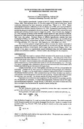
Hydrotreating experiments for <strong>Two</strong>-<strong>Stage</strong> <strong>Process</strong> <strong>with</strong><br />
Gas/Liquid Separation. The description of <strong>Two</strong> –<strong>Stage</strong> process<br />
pilot plant is shown in Figure 1. <strong>Two</strong> fixed bed reactors in seriesflow<br />
configuration are used for the hydrotreating experiments. A<br />
high pressure separator and a stripper <strong>with</strong> H 2 gas were equipped<br />
between the 1st-stage and 2nd-stage reactors as a gas/liquid<br />
separation system. The 1st-stage product oil through the gas/liquid<br />
separation system and fresh H 2 were supplied to the 2nd-stage reactor.<br />
All the experiments were performed under the conditions of P(H 2)<br />
5.0 MPa, H2/Oil 200 NL/L for each reactor, and total LHSV 1.5 h -1 .<br />
Reaction temperature was a variable to obtain various product sulfur<br />
levels.<br />
Feed + H2<br />
Reactor<br />
H2<br />
Stripper<br />
H2<br />
Separator<br />
Gas (H2S)<br />
Reactor<br />
Figure 1. Description of <strong>Two</strong> –<strong>Stage</strong> process pilot plant<br />
Products<br />
Feedstock<br />
Middle-east straight-run gas oil fraction was used as feedstock of<br />
hydrotreating experiments. Properties are summarized in Table 1.<br />
Table 1. Properties of Feedstock<br />
Item Unit Feedstock<br />
Density@15 Ž [g/cm 3 ] 0.849<br />
<strong>Sulfur</strong> [wtppm] 16900<br />
Nitrogen [wtppm] 61<br />
Distillation (ASTM D 86) IBP [ o C] 223<br />
T10% [ o C] 256.5.<br />
T50% [ o C] 287<br />
T90% [ o C] 331.5<br />
EP [ o C] 347<br />
<strong>Fuel</strong> Chemistry Division Preprints 2002, 47(2), 460
Analysis<br />
<strong>Sulfur</strong> content of product oil was determined <strong>by</strong> XRF. GC-SCD<br />
analysis was also conducted to determine DBT, 4-MDBT, and 4,6-<br />
DMDBT.<br />
Results and Discussion<br />
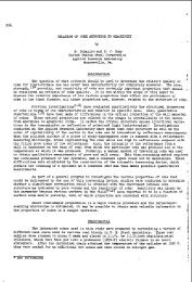
Concept of <strong>Two</strong>-<strong>Stage</strong> <strong>Process</strong> <strong>with</strong> Gas/Liquid Separation.<br />
Conceptual diagram of the sulfur compound distribution in two-stage<br />
process <strong>with</strong> gas/liquid separation is shown in Figure 2. In the 1ststage,<br />
HDS of "Reactive <strong>Sulfur</strong> Compounds" is perfectly carried out.<br />
As a result of the HDS and HDN reactions in the 1st-stage, a large<br />
amount of hydrogen sulfide and ammonia are produced. These<br />
compounds seriously inhibit HDS of "Refractory <strong>Sulfur</strong> Compounds"<br />
in the 2nd-stage. Removal of these inhibitors between the 1st-stage<br />
and the 2nd-stage accelerates HDS in the 2nd-stage. Based on the<br />
estimation of gas/liquid equilibrium, 86% of hydrogen sulfide can be<br />
removed, and more H 2S can be removed <strong>by</strong> application of stripping<br />
<strong>with</strong> H 2.<br />
NiW catalyst can be applied to the 2nd-stage because the<br />
concentration of hydrogen sulfide and ammonia is comparatively low.<br />
NiW catalyst is superior to the CoMo catalyst and NiMo catalyst in<br />
the presence of low concentrations of hydrogen sulfide.<br />
Figrure 2. Conceptual diagram of the sulfur compound distribution<br />
in two-stage process <strong>with</strong> gas/liquid separation<br />
Performance of <strong>Two</strong>-<strong>Stage</strong> <strong>Process</strong> <strong>with</strong> Gas/Liquid<br />
Separation. The performance of two-stage process <strong>with</strong> gas/liquid<br />
separation is shown in Table 2. In the base case, both the 1st-stage<br />
and 2nd-stage catalysts are CoMo catalyst and gas/liquid separation<br />
is not employed. The required reaction temperature for 50ppm<br />
product sulfur is 356 o C.<br />
In the case of only process improvement, both the 1st-stage and 2ndstage<br />
catalysts are CoMo catalyst and gas/liquid separation is<br />
employed. The required reaction temperature for 50ppm product<br />
sulfur is 336 o C. Simple application of the gas/liquid separation<br />
<strong>with</strong>out modifying the catalyst improves 20 o C of the required<br />
reaction temperature for 50ppm-sulfur diesel production.<br />
In the case of both process and catalyst improvements, the 1st-stage<br />
and the 2nd-stage catalysts are CoMo catalyst and NiW catalyst,<br />
respectively. Gas/liquid separation is employed. The required<br />
reaction temperature for 50ppm product sulfur is 332 o C. Application<br />
of the gas/liquid separation system and NiW catalyst for the 2ndstage<br />
improves 24 o C of the required reaction temperature for 50ppmsulfur<br />
diesel production relative to the base case. (4 o C lower reaction<br />
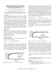
temperature than the case of only process improvement). Figure 3<br />
shows the potential to “sulfur free” diesel production.<br />
In case of applying the NiW catalyst to the 2nd-stage, it is possible<br />
to produce 15ppm-sulfur diesel and 5ppm-sulfur diesel at 340 o C and<br />
at 350 o C, respectively.<br />
lnkHDS<br />
6.5<br />
6.0<br />
5.5<br />
5.0<br />
4.5<br />
4.0<br />
3.5<br />
3.0<br />
350 Ž<br />
5ppm<br />
340 Ž<br />
15ppm<br />
1.60 1.62 1.64 1.66 1.68 1.70<br />
1000/T [K -1 ]<br />
CoMo/CoMo<br />
CoMo/NiW<br />
Figure 3. Potential to “sulfur free(S = 10 ppm or less)” diesel<br />
production <strong>by</strong> two-stage process <strong>with</strong> gas/liquid separation. (Feed 3,<br />
P(H 2): 5.0 MPa, H2/Oil: 200 NL/L, Total LHSV: 2.0 h-1)<br />
1st-stage (50vol%) / Separator / H 2S Stripper / 2nd-stage (50vol%)<br />
Table 2. Performance of <strong>Two</strong>-<strong>Stage</strong> <strong>Process</strong> <strong>with</strong> Gas/Liquid<br />
Separation<br />
Improvement Base <strong>Process</strong> Proscess & Catalyst<br />
1st -stage catalyst CoMo CoMo CoMo<br />
Gas/Liquid Separation No Yes Yes<br />
2nd-stage catalyst CoMo CoMo NiW<br />
Required Reaction Temperature<br />
for 50 ppm Product <strong>Sulfur</strong><br />
356 336 332<br />
Conclusions<br />
The two-stage process <strong>with</strong> gas/liquid separation not only achieves<br />
ultra-low sulfur diesel production (S = 50ppm or less) under more<br />
beneficial conditions but also has great potential to sulfur-free diesel<br />
production (S = 10ppm or less). Removal of produced hydrogen<br />
sulfide and ammonia in the middle of the unit accelerates HDS of the<br />
following 2nd-stage. NiW catalyst can be applied to the 2nd-stage.<br />
Acknowledgement. The Research of the two-stage process <strong>with</strong><br />
gas/liquid separation has been entrusted <strong>by</strong> the New Energy and<br />
Industrial Technology Development Organization under a subsidy of<br />
the Ministry of Economy, Trade and Industry.<br />
References<br />
1) http://www.env.go.jp/press/file_view.php3?serial=791&hou_id=1243.pdf<br />
(November 1, 2000, Japanese).<br />
2) http://www.epa.gov/fedrgstr/EPA-AIR/2000/June/Day-02/ (June 2, 2000).<br />
3) http://www.bmu.de/presse/2001/pm599.htm (March 13, 2001).<br />
4)http://europa.eu.int/rapid/start/cgi/guesten.ksh?p_action.gettxt=gt&doc=IP/0<br />
1/681|0|AGED&lg=EN (May 11, 2001).<br />
5) Kabe, T.; Ishihara, A.; Qian, W. “Hydrodesulfurization and<br />
Hydrodenitrogenation<br />
Chemistry and Engineering”, Kodansha, Tokyo<br />
(1999)<br />
and cited therein.<br />
6) Koide, R.; Goto, Y.; Kawabata, M.; Ishida, K. Prepr. Div. Petrol. Chem.,<br />
Am. Chem. Soc., 2001, 46, 398-401.<br />
<strong>Fuel</strong> Chemistry Division Preprints 2002, 47(2), 461