Manual - UEi Automotive
Manual - UEi Automotive
Manual - UEi Automotive

You also want an ePaper? Increase the reach of your titles
YUMPU automatically turns print PDFs into web optimized ePapers that Google loves.
Introduction<br />
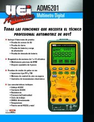
The ADM5201 advanced handheld automotive multimeter combines all<br />
the features of a full function multimeter and integrates the functions of<br />
an O2 Sensor tester, PFI & TBI Fuel Injection testers. The ADM5201<br />
provides a quick and accurate diagnosis of the complete O2 circuit. It is<br />
also capable of sending a Rich/Lean signal to the ECM, and displaying<br />
crossing-per-second (CC) and O2 voltage simultaneously, when secondary<br />
display shows test results. This professional grade multimeter provides<br />
efficient trouble shooting solutions to the most difficult problems<br />
encountered in today’s sophisticated automotive electronic systems.<br />
The ADM5201 has a bright LED backlight. A battery access door allow s<br />
users to replace the battery and fuse without breaking ca l i b ration seals!<br />
High impact over-molded case absorbs shock over more of the case than a<br />
conventional rubber boot design. Convenient closed case ca l i b ration<br />
a l l ows adjustments to be made directly through the Optica l l y - I s o l a t e d<br />
RS 232 serial port.<br />
Features include<br />
• Testing functions include: O2 Sensor Test, Ground Test, Battery and<br />
Alternator Charging System Test, and Battery Drain Test<br />
• Accurate RPM measurements for 2 and 4 stroke automotive<br />
engines with 1 to 12 cylinders using the inductive pickup<br />
• ms-Pulse Width function to test on-time of both PFI type and TBI<br />
type fuel injectors<br />
• Duty Cycle and direct DWELL reading<br />
• 4 step adjustable triggers on 1 to 12 cylinders<br />
• Temperature measurement up to 2,372˚F or 1,300˚C<br />
• 4-4/5 digit, 50,000 count primary and 9,999 count secondary dual<br />
display with bar-graph (Frequency range: 99,999 counts)<br />
• Backlit display<br />
• RS-232C optically isolated serial port<br />
• Memory store and recall (20 locations)<br />
• Auto hold. 50ms high speed MIN/MAX/Avg, & relative mode<br />
• 1ms Peak Mode<br />
• Auto-power off<br />
• High impact over-molded case<br />
Safety Notes<br />
Before using this meter, read all safety information carefully. In<br />
this manual the word "WARNING" is used to indicate conditions<br />
or actions that may pose physical hazards to the user. The word<br />
"CAUTION" is used to indicate conditions or actions that may<br />
damage this instrument.<br />
• DO NOT attempt to use this meter if either the meter or the test<br />
leads have been damaged. Send unit in for repair by a qualified<br />
repair facility<br />
• Test leads must be fully inserted prior to taking measurements<br />
• Never attempt a voltage measurement with the test leads inserted<br />
into the “A” terminal and the “C OM” terminal - The “A” terminal is<br />
protected by a fuse. You might be injured or damage the meter<br />
• Always disconnect the live test lead before disconnecting the<br />
common test lead from a circuit<br />
• Turn the engine off before connecting or disconnecting inductive<br />
pickup to avoid a shock.<br />
• Disconnect the test leads from the test points before changing<br />
functions to avoid damaging the meter when testing above 350V AC<br />
• Choose the proper range and function for the measurement -<br />
Always set the meter to the highest range and work downward for<br />
an unknown value if you are using manual ranging mode<br />
• Do not try voltage or current measurements that may exceed the<br />
ratings marked on the input limit for switch or terminal<br />
• Use current probes to measure circuits exceeding 10A<br />
• Disconnect the “LIVE” test lead before disconnecting the<br />
“COMMON” test lead<br />
• Do not test a recently recharged lead-acid battery<br />
• Disconnect the power and discharge all high-voltage capacitors<br />
before testing in the resistance, continuity, and diode functions<br />
• If the engine has been running, do not place the meter and its<br />
accessories near the engine or the exhaust manifold which might<br />
be hot and can damage the meter<br />
• If any of the following indications occur during testing, turn<br />
off the power source to the circuit under test:<br />
• Arcing<br />
• Flame<br />
• Smoke<br />
• Extreme Heat<br />
• Smell of Burning Materials<br />
• Discoloration or Melting of Components<br />
• Read the safety precautions associated with the equipment being<br />
tested and seek assistance or advice when performing<br />
unfamiliar tasks.<br />
• Keep your fingers away from the test lead metal probe contacts<br />
and bus-bars when making measurements. Always grip the<br />
instrument and test-leads behind the hand guards (molded into<br />
the probes).<br />
• In the event of electrical shock, ALWAYS bring the victim to<br />
the emergency room for evaluation, regardless of the victim’s<br />
apparent recovery. Electrical shock can cause an unstable heart<br />
rhythm that may need medical attention.<br />
WARNING!<br />
Exceeding the specified limits of this meter is dangerous and can<br />
expose the user to serious or possibly fatal injury.<br />
International Symbols<br />
• DO NOT attempt to measure any voltage that exceeds 600 volts<br />
with this meter - <strong>UEi</strong> offers numerous alternatives for measuring<br />
high voltage and current<br />
• Voltages above 600 volts DC or 25 volts AC may constitute a<br />
serious shock hazard<br />
ADM5201-MAN P. 1