INSTRUCTION MANUAL - UEi Automotive
INSTRUCTION MANUAL - UEi Automotive
INSTRUCTION MANUAL - UEi Automotive

You also want an ePaper? Increase the reach of your titles
YUMPU automatically turns print PDFs into web optimized ePapers that Google loves.
<strong>INSTRUCTION</strong> <strong>MANUAL</strong><br />
DL49<br />
1-800-547-5740 • Fax: (503) 643-6322<br />
www.ueiautomotive.com • email: info@ueitest.com
Introduction<br />
The DL49 is a hand-held, battery powered, digital multimeter with clampon<br />
current measuring ca p a b i l i ty. This instrument is ideal for anyone that<br />
needs to make quick, accurate measurements of voltage, resistance, and<br />
AC or DC inductive ampera g e .<br />
Features include<br />
• UL listed 3111-1<br />
• Six measurement functions<br />
1. AC inductive amps (to 400 amps)<br />
2. DC inductive amps (to 400 amps)<br />
3. AC Volts<br />
4. DC Volts<br />
5. Ohms<br />
6. Continuity (with audible alert)<br />
• Autoranging<br />
• AC amperage peak-hold<br />
• Data hold for volt, ohm, and amperage functions<br />
• Low battery indicator<br />
• Auto continuity<br />
• Auto power off<br />
• Rugged construction<br />
• Surge protection<br />
• Compact size for easy access to tight areas<br />
• If any of the following indications occur during testing, turn<br />
off the power source to the circuit under test:<br />
• Arcing<br />
• Flame<br />
• Smoke<br />
• Extreme Heat<br />
• Smell of Burning Materials<br />
• Discoloration or Melting of Components<br />
• Read the safety precautions associated with the equipment being<br />
tested and seek assistance or advice when performing<br />
unfamiliar tasks.<br />
• Keep your fingers away from the test lead metal probe contacts<br />
and bus-bars when making measurements. Always grip the<br />
instrument and test-leads behind the hand guards (molded into<br />
the probes).<br />
• In the event of electrical shock, ALWAYS bring the victim to<br />
the emergency room for evaluation, regardless of the victim’s<br />
apparent recovery. Electrical shock can cause an unstable heart<br />
rhythm that may need medical attention.<br />
International Symbols<br />
Safety Notes<br />
Before using this meter, read all safety information carefully. In<br />
this manual the word "WARNING" is used to indicate conditions<br />
or actions that may pose physical hazards to the user. The word<br />
"CAUTION" is used to indicate conditions or actions that may<br />
damage this instrument.<br />
WARNING!<br />
Exceeding the specified limits of this meter is dangerous and can<br />
expose the user to serious or possibly fatal injury.<br />
• DO NOT attempt to measure any voltage that exceeds 600 volts<br />
with this meter - <strong>UEi</strong> offers numerous alternatives for measuring<br />
high voltage and current<br />
• Voltages above 60 volts DC or 25 volts AC may constitute a<br />
serious shock hazard<br />
• DO NOT attempt to use this meter if either the meter or the test<br />
leads have been damaged. Send unit in for repair by a qualified<br />
repair facility<br />
• Test leads must be fully inserted prior to taking measurements<br />
• Always turn off power to a circuit (or assembly) under test before<br />
cutting, unsoldering or breaking the current path. Even small<br />
amounts of current can be dangerous<br />
• Always disconnect the live test lead before disconnecting the<br />
common test lead from a circuit<br />
• When measuring high voltage, disconnect the power source before<br />
making test lead connections. Connect the test leads to the meter<br />
first then to the circuit under test. Reapply power<br />
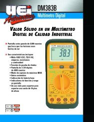
C o n t rols and Indicators<br />
1. C l a m p : Used to measure inductive AC and DC current.<br />
Opens to 1 1/2” (40 mm).<br />
CAUTION!<br />
The clamp uses a high-tension spring to close the jaw. DO NOT allow<br />
fingers or objects to become pinched in the base as jaw closes.<br />
2. Conductor Alignment Marks: Used to aid in the visual<br />
alignment of a conductor when measuring inductive ampera g e .<br />
Greatest accura cy is achieved when the conductor inside the clamp<br />
is centered at the intersection of these marks.<br />
3. Hand Guard: Used as a point of reference for the operator’s safety.<br />
WARNING!<br />
Always keep your hands and fingers behind the hand guards when<br />
measuring current on exposed conductors. Contact may result<br />
in serious safety.<br />
DL49-MAN P. 1
4. Data Hold Push-button: Freezes the value displayed on the<br />
digital read-out.<br />
5. Peak Hold Push-button: Used to capture the highest AC<br />
inductive amp reading and to automatically zero (approximately) the<br />
inductive DC amp readings.<br />
6. Clamp Lever: Opens and closes current clamp jaw.<br />
7. Rotary Function Switch: Used to power the meter on and off, or<br />
to select one of the available measurement functions.<br />
NOTE: Measure inductive AC and DC current using the clamp.<br />
Measure volts AC and DC, resistance and continuity at the<br />
test lead inputs.<br />
8. Off Position: Turns the meter off. Always store your meter in the<br />
off position. If the meter will not be used for a month or more,<br />
remove the batteries.<br />
9. Display: C o m m u n i cates function, range, and value information to<br />
the user.<br />
10. Common Terminal: The black test lead is plugged into this<br />
terminal to supply the ground or “low” reference for<br />
all measurements.<br />
11. Volt/Ohm (Ω) Terminal: The red lead is plugged into this<br />
terminal. It is used for AC/DC volts, ohms, and continuity measurements.<br />
12. Maximum Input Statements: M AX 600V indicates that a<br />
m aximum of 600 Volts can be applied between the two terminals of<br />
b e tween earth ground and any terminal.<br />
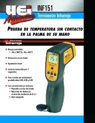
LCD Display Functional Description<br />
1. Peak Hold: I n d i cates the meter is displaying the maximum inductive<br />
AC current value recorded.<br />
2. Continuity: I n d i cates the meter is in the continuity measurement<br />
mode and will sound a tone when measuring resistance below<br />
approximately 50 ohms.<br />
3. Data Hold: I n d i cates the value displayed is held on screen<br />
(the data hold button is pressed).<br />
4. Low Battery Indicator: This symbol appears when the battery<br />
needs replacement.<br />
NOTE: A low battery will adversely affect accuracy.<br />
5. AC: I n d i cates that alternating current/voltage is being measured.<br />
6. Minus: I n d i cates the value measured has a negative polarity.<br />
7. DC: I n d i cates that direct current/voltage is being measured.<br />
8. mVA: I n d i cates that millivolts (mV), volts (V), milliamps (mA) or<br />
amps (A) is being displayed.<br />
9. MKΩ: Indicates that Megohms, Kilohms, or ohms are<br />
being displayed.<br />
10. Numerical Value: Displays the total value of the units displayed.<br />
4<br />
1<br />
2 3<br />
2<br />
1<br />
3<br />
5<br />
6<br />
7<br />
8<br />
9<br />
6<br />
4<br />
5<br />
7<br />
8<br />
Operating Instructions<br />
Auto-Power Off<br />
This instrument automatically shuts off after 30 minutes of inactivity. The<br />
meter is considered active when there is a change of at least 10 digits<br />
during this period (for example: the meter senses a change from 24.04<br />
volts to 24.14 volts).<br />
10<br />
10 11<br />
9<br />
Autorange Resolution<br />
This instrument automatically selects the range that gives you the best<br />
resolution for the function and value measured. As the meter seeks the<br />
appropriate range, the display may briefly display an overload (OFL)<br />
indication or show quickly changing values until it stabilizes.<br />
12<br />
DL49-MAN P. 2
Peak Hold<br />
When measuring AC amps you can use the PEAK HOLD button on<br />
the right side of the instrument to capture the highest measured value.<br />
Press and hold until the word PEAK appears along the top of the<br />
display and only the highest measured value will be displayed on the<br />
LCD. Press and hold a second time or change functions to return to<br />
real-time measurement.<br />
Data Hold<br />
The DATA HOLD button freezes the reading displayed on the LCD at<br />
the moment it is passed. To engage data hold, press the HOLD button,<br />
located on the face of the instrument. When this function is active, the<br />
symbol “D.H” appears on the digital display. To cancel data hold, press<br />
the data hold button again, or select any other measurement function<br />
using the rotary function select switch.<br />
Rotary Function Select Switch<br />
The rotary function select switch is used to select the measurement<br />
mode and to turn the meter on and off.<br />
CAUTION!<br />
Set the rotary function select switch to the appropriate setting before<br />
connecting the test leads to circuits under test. Observe those safety<br />
precautions outline in the beginning of this manual.<br />
Measuring Inductive Current<br />
The inductive current measurement mode relies on the induced<br />
electromagnetic field that occurs when electricity flows through a<br />
conductor. Prepare for measurement be separating a single live<br />
conductor from any other phase, neutral or ground conductor.<br />
Squeeze the clamp lever, and place the conductor in the open jaws.<br />
To attain the most accurate reading, ensure the conductor is centered<br />
in the jaws of the clamp, and the jaws are closed tight. The conductor<br />
must be able to fit inside the 1 1/4” (32 mm) fully closed jaws.<br />
To measure inductive AC current:<br />
1. Place the function select switch in the AC amp position.<br />
2. Place the clamp jaw around a live conductor (as described above).<br />
3. Allow meter to stabilize - Observe reading.<br />
The maximum limit for this function is 400 amps AC. Too much current<br />
will saturate the ferrous material in the clamp, and adversely affect<br />
accuracy.<br />
WARNING!<br />
DO NOT attempt to take any unknown voltage or current<br />
measurements that may be in excess of this meter’s maximum limits.<br />
To avoid the risk of electrical shock and instrument discharge, open<br />
circuit voltage for the circuit under test must not exceed 600 volts<br />
(RMS). Consider using an optional high voltage probe for high<br />
power situations.<br />
Measuring Voltage<br />
WARNING!<br />
Input voltages must not exceed 600 volts. High voltages and currents<br />
require greater awareness of physical safety hazards.<br />
Before connecting the test leads; turn off the power to the circuit under<br />
test; set the meter to the desired function and range; connect the test<br />
leads to the meter first, then to the circuit under test. Reapply pow e r. If<br />
an erroneous reading is observed, disconnect power immediately and<br />
recheck all settings and connections.<br />
When taking voltage measurements your meter must be connected in<br />
p a rallel to the circuit, or circuit element, under test.<br />
To measure DC or AC volts;<br />
1. Set the rotary function select switch to the desired AC or<br />
DC voltage position.<br />
2. Disconnect the power from the circuit to be tested.<br />
3. Connect the test leads to the circuit to be tested.<br />
4. Reapply power to the circuit. The measured voltage will<br />
be displayed.<br />
5. If the input to the V/Ω port is lower (more negative) than the<br />
black COM port, a minus sign (negative polarity) will appear on<br />
the left of the display.<br />
6. Disconnect power to the circuit before removing attached test<br />
leads from the circuit.<br />
NOTE: During continuity or resistance measurements, polarity<br />
does not matter.<br />
Measuring Resistance<br />
CAUTION!<br />
Turn off power and discharge all capacitors on the circuit to be tested<br />
before attempting “in circuit” resistance measurements. Failure to do so<br />
may result in equipment or instrument damage. It is critical to both the<br />
welfare of the meter, and the accuracy of the measurement, that you<br />
remove all power to the circuit under test when making resistance<br />
measurements. If any voltage is present in the test circuit, whether<br />
from a conventional power supply, or energy stored in a capacitor, an<br />
erroneous reading will result. This meter may be damaged if more than<br />
600 volts are present.<br />
NOTE: When measuring critically low ohm values, touch tips of test<br />
leads together and record the test lead resistance value. Subtract<br />
this value from the total circuit resistance to obtain the most<br />
accurate reading.<br />
NOTE: For all measurements requiring the use of the meter leads,<br />
insert the red lead into the V/Ω port and the black lead into the<br />
COM port.<br />
DL49-MAN P. 3
For resistance measurements above one megohm the display<br />
might take a few seconds to stabilize. This is normal for high<br />
resistance readings.<br />
To measure resistance, follow these steps:<br />
1. Set the rotary switch to the resistance function.<br />
2. Turn off power to the circuit under test and ensure there is no<br />
residual voltage present from any source.<br />
3. Touch the probes to the test points and read the display. The meter<br />
beeps as it seeks the correct range to measure the circuit’s<br />
resistance. Be sure you have good contact between the test leads<br />
and the circuit. Dirt, oil, solder-flux or other foreign matter alters the<br />
reading value.<br />
Measuring Continuity<br />
Use the continuity mode to make quick checks for connection of<br />
electrical circuits, such as electrical wiring, switch contacts, relays and<br />
audio cables. In the continuity mode, an audible tone sounds when the<br />
value measured is approximately 50Ω or less.<br />
To test for continuity, follow these steps:<br />
1. Set the rotary switch to the continuity function.<br />
2. Place one probe to each side of the circuit to be tested. If the<br />
circuit measures approximately 50Ω or less, the meter will sound<br />
a continuous tone.<br />
NOTE: When servicing the meter, use only the replacement parts specified.<br />
Battery: 9V, NEDA 1604 or IEC 6LR 61<br />
Test lead set: ATL55<br />
Cleaning and Decontamination<br />
Periodically clean your meter’s case using a damp cloth. DO NOT use<br />
abrasives, cleaning solvents or strong detergents, as they may damage<br />
the finish or affect the reliability of the structural components.<br />
Battery Replacement<br />
Always use a fresh replacement battery of the specified size and type.<br />
Immediately remove the old or weak battery from the meter and<br />
dispose of it in accordance with your local disposal regulations. Old or<br />
defective batteries can leak chemicals that corrode electronic circuits.<br />
WARNING!<br />
To avoid electric shock, be sure to turn off the meter’s power and<br />
disconnect both test leads from any equipment before you remove<br />
or install batteries.<br />
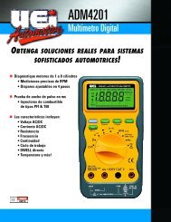
To install a new battery, follow these procedures:<br />
1. Remove the screw from the battery compartment cover on the<br />
back (lower half) of the meter and lift the cover (Fig 1).<br />
2. Remove and discard the old battery. Always dispose of old batteries<br />
promptly in a manner consistent with local disposal regulations.<br />
Periodic service<br />
M a i n t e n a n c e<br />
WARNING!<br />
Under NO circumstance should you expose batteries to extreme heat or<br />
fire as they may explode and cause injury.<br />
3. Place a fresh 9V battery in the compartment.<br />
WARNING!<br />
Repair and service of this instrument is to be performed by qualified<br />
personnel only. Improper repair or service could result in physical<br />
degradation of the meter. This could alter the protection from<br />
electrical shock and personal injury this meter provides to the<br />
operator. Perform only those maintenance tasks that you are<br />
qualified to do.<br />
NOTE: If you do not plan to use the meter for a month or more,<br />
remove the battery and store it in an area that won’t be damaged by a<br />
leaking battery.<br />
4. Reattach the battery compartment cover to the meter and<br />
reinstall the screw.<br />
These guidelines will help you attain long and reliable service from<br />
your meter:<br />
1. Calibrate your meter annually to ensure it meets original<br />
performance specifications.<br />
2. Keep your meter dry. If it gets wet, wipe it dry immediately. Liquids<br />
damage electronic circuits.<br />
3. Whenever pra c t i cal, keep the meter away from dust and dirt, which<br />
can cause premature wear.<br />
4. Although your meter is built to withstand the rigors of daily use, it<br />
can be damaged by severe impacts. Use reasonable caution when<br />
using and storing the meter.<br />
Remove cover<br />
DL49-MAN P. 4<br />
(Fig 1)
S p e c i f i c a t i o n s<br />
Standard & Optional Accessories<br />
Measurement limits<br />
Frequency<br />
AC Amperage<br />
DC Amperage<br />
AC Voltage<br />
DC Voltage<br />
Ohms<br />
Continuity<br />
General specifications<br />
Size (H x W x L)<br />
Operating temperature<br />
Storage temperature<br />
Relative humidity<br />
(storage and use)<br />
Weight<br />
Calibration frequency<br />
Ul listing<br />
IEC Listing<br />
Battery<br />
Battery life<br />
50 - 400 Hz<br />
400 Amps<br />
400 Amps<br />
600 Volts<br />
600 Volts<br />
40 Megohms<br />
DL49<br />
Digital Clamp-On Multimeter<br />
Limited Warranty<br />
The DL49 is warranted to be free from defects in materials and workmanship for a period of<br />
three years from the date of purchase. If within the warra n ty period your instrument should<br />
become inoperative from such defects, the unit will be repaired or replaced at <strong>UEi</strong>’s option.<br />
This warra n ty covers normal use and does not cover damage which occurs in shipment or<br />
failure which results from alteration, tampering, accident, misuse, abuse, neglect or improper<br />
maintenance. Batteries and consequential damage resulting from failed batteries are not<br />
covered by warra n ty.<br />
Any implied warranties, including but not limited to implied warranties of merchantability<br />
and fitness for a particular purpose, are limited to the express warranty. <strong>UEi</strong> shall not be<br />
liable for loss of use of the instrument or other incidental or consequential damages,<br />
expenses, or economic loss, or for any claim or claims for such damage, expenses or<br />
economic loss. A purchase receipt or other proof of original purchase date will be required<br />
before warra n ty repairs will be rendered. Instruments out of warra n ty will be repaired (when<br />
r e p a i rable) for a service charge. Return the unit postage paid and insured to:<br />
1-800-547-5740 • FAX: (503) 643-6322<br />
www.ueiautomotive.com • Email: info@ueitest.com<br />
This warranty gives you specific legal rights. You may also have other rights which vary from<br />
state to state.<br />
PLEASE<br />
RECYCLE<br />
Copyright © 2007 <strong>UEi</strong> <strong>Automotive</strong> DL49-MAN 1/07