BMP Monitoring Sites - Urban Drainage and Flood Control District
BMP Monitoring Sites - Urban Drainage and Flood Control District
BMP Monitoring Sites - Urban Drainage and Flood Control District

Create successful ePaper yourself
Turn your PDF publications into a flip-book with our unique Google optimized e-Paper software.
UDFCD <strong>BMP</strong> MONITORING SITES<br />
Overview<br />
Overview<br />
At all of the Best Management Practice (<strong>BMP</strong>) sites monitored by the <strong>District</strong>,<br />
inflow <strong>and</strong> outflow samples are collected - along with rainfall <strong>and</strong> runoff data – to<br />
determine the Event Mean Concentration (EMC) of different constituents <strong>and</strong> to<br />
assess the functionality of each <strong>BMP</strong> on stormwater runoff reduction <strong>and</strong> water<br />
quality.<br />
The monitoring sites are set up in April <strong>and</strong> taken down in October with periodic<br />
maintenance throughout the sampling season.<br />
Types of <strong>BMP</strong>s Monitored by <strong>District</strong>
UDFCD <strong>BMP</strong> MONITORING SITES<br />
Pervious Pavement<br />
PERVIOUS PAVEMENT<br />
Pervious pavements encompass a variety of stabilized surfaces that can be used<br />
for the movement <strong>and</strong> parking of vehicles <strong>and</strong> storage of materials <strong>and</strong><br />
equipment. It differs from conventional pavement: it is designed to infiltrate<br />
stormwater runoff instead of shedding it off the surface. Pervious pavement<br />
offers the advantage of decreasing the effective<br />
imperviousness of an urbanizing or redevelopment site,<br />
thereby reducing runoff <strong>and</strong> pollutant loads leaving the site.<br />
Pervious pavement can be designed with or without<br />
underdrains. Whenever underdrains are used, infiltrated<br />
water will behave similar to interflow <strong>and</strong> will surface at a<br />
much reduced rate over extended periods of time. All types<br />
of pervious pavements help to return stormwater runoff<br />
hydrology to more closely resemble pre-developed<br />
conditions. However, the actual consumptive use of water falling onto the ground<br />
is considerably less than under pre-developed conditions <strong>and</strong> for grass lawns in<br />
urban areas. Consult with a geotechnical engineer as to the suitability of<br />
each type of pervious pavement for the loads <strong>and</strong> traffic it will support <strong>and</strong> carry<br />
<strong>and</strong> the geologic conditions the pavement will rest upon.<br />
Pervious Pavements Monitored by <strong>District</strong>
UDFCD <strong>BMP</strong> MONITORING SITES<br />
Pervious Concrete Pavement<br />
PERVIOUS CONCRETE<br />
PAVEMENT<br />
Description Location Typical Details Installation<br />
Photo Gallery <strong>Monitoring</strong> Data Other Examples<br />
Description<br />
General<br />
Pervious concrete pavement is a relatively new type of permanent surfacing. It is<br />
a monolithically poured pervious concrete pavement that has 15% to 21% of its<br />
volume as void. These voids within the concrete are<br />
achieved by eliminating the fine s<strong>and</strong> aggregate<br />
from the concrete mix. They provide the flow paths for<br />
rainwater from the surface of the pavement to the<br />
base course underlying it. Because the integrity of the<br />
concrete structure may be harmed by st<strong>and</strong>ing water<br />
during freezing weather, the use of pervious concrete<br />
pavement is not recommended for use in<br />
pervious pavement detention installations. It is<br />
critical that sufficient aggregate base course layer is<br />
provided under the pervious concrete slab to store the<br />
runoff <strong>and</strong> allow it to infiltrate slowly into the ground<br />
<strong>and</strong> drained using an underdrain pipe system. Having a sufficiently thick layer of<br />
aggregate base course is particularly critical during the months of the year when<br />
freezing of water can occur.<br />
Site Specific<br />
The pervious concrete pavement site monitored by the<br />
<strong>District</strong> is located in Lakewood. Modular block pavement<br />
was monitored in this location from 1994-2004. In 2005,<br />
the modular block was replaced with the pervious concrete<br />
pavement that is currently in place. Two separate pads of<br />
pervious concrete pavement were placed using different<br />
aggregate sizes for the base course. The east pad used
UDFCD <strong>BMP</strong> MONITORING SITES<br />
Pervious Concrete Pavement<br />
AASHTO #67 <strong>and</strong> the west pad used AASHTO #8. Below the surface, there<br />
are two lateral flow barriers in the form of concrete walls. At each barrier, the<br />
filtered water is collected in perforated pipes <strong>and</strong> carried to a manhole located<br />
adjacent to the pervious concrete pavement. Inside the manhole a riser pipe with<br />
an orifice is sized to drain the entire gravel pore volume of each cell<br />
in 6 hours or more. A riser pipe with a levelogger is located just upstream of<br />
each manhole to measure the flow coming from each cell. All flows from the<br />
pervious concrete pavement are combined <strong>and</strong> discharge east of the site through<br />
a V-notched weir where a pressure transducer measures the depth of flow<br />
<strong>and</strong> sends the data into the sampler.<br />
Adjacent to the pervious concrete pavement watershed is a control<br />
watershed of traditional asphalt pavement used to compare results of treated<br />
runoff to untreated, direct runoff. Stormwater runoff from the control watershed is<br />
collected in a sump catch basin at the northeast corner of the site. Water is<br />
conveyed a short distance to the outfall <strong>and</strong> flows through an H-flume where<br />
flow is measured by a pressure transducer.<br />
The sampling equipment is stored in a shed near the outlet works. A rain gage<br />
on top of the shed measures rainfall <strong>and</strong> signals the ISCO samplers inside the<br />
shed to begin sampling after 0.1 inches of rain falls. The samplers then draw a<br />
sample of water from both the pervious concrete pavement runoff <strong>and</strong> the control<br />
runoff after ??? cfs has passed, <strong>and</strong> then every 15 minutes until 12 hours after<br />
the storm has ended.
UDFCD <strong>BMP</strong> MONITORING SITES<br />
Pervious Concrete Pavement<br />
Test Site Location<br />
The pervious concrete pavement test site is in the Lakewood City Shops<br />
maintenance buildings located at 850 Parfet Street. The pervious concrete<br />
pavement itself is located in the parking lot on the east side of the property, east<br />
of the building.<br />
Map this Location<br />
The watershed area tributary to the pervious concrete pavement is 9050 square<br />
feet, with the pervious concrete taking up 2000 square feet of that area. The<br />
watershed consists primarily of impervious areas, including buildings, parking lots<br />
<strong>and</strong> paved areas.<br />
The test site consists of three main parts: the control shed, the pervious<br />
concrete pavement itself, <strong>and</strong> the outlet.
Pervious Concrete Watershed<br />
UDFCD <strong>BMP</strong> MONITORING SITES<br />
Pervious Concrete Pavement
UDFCD <strong>BMP</strong> MONITORING SITES<br />
Pervious Concrete Pavement<br />
Typical Details<br />
Use utility vault w/<br />
lid to collect<br />
underdrains.<br />
Monolithically poured porous<br />
concrete.<br />
1in<br />
5"**<br />
D = 0.67'(8") min.**<br />
1" (min.) C-33 S<strong>and</strong><br />
6" (min.)<br />
Underdrain<br />
trench<br />
6" (min.) trench depth<br />
16 MIL (mon.) plastic impermeable membrane<br />
on top of subgrade when required <strong>and</strong> at bottom<br />
of underdrain trench.<br />
Woven geotextile fabric meeting:<br />
ASTM D4751-AOS US Std. Sieve #50 to #70,<br />
ASTM D4633 min. trapezoidal tear strength 100 x 60 lbs,<br />
Minimum COE specified open area of 4%.<br />
Section A-A<br />
** For personal vehicles & pickup trucks.<br />
Thicker section may be required for<br />
heavier vehicles.<br />
Consult with pavement engineer for<br />
needed thickness of concrete slab.<br />
*** Base course: AASHTO #67, #8 or #4 aggregate<br />
with all fractured faces.<br />
So = 0% to 2% (max.)<br />
Lmax = D/(1.5*So)<br />
A<br />
Monolithically poured porous concrete<br />
(mix of AASHTO #8 or #67 gravel<br />
<strong>and</strong> portl<strong>and</strong> cement per specifications<br />
in the <strong>BMP</strong> Details <strong>and</strong> Specifications<br />
Chapter of this Manual). No phosphorous<br />
based admixtures allowed in the PCP mix.<br />
5"**<br />
D = 0.67'(8") min.**<br />
So = 1% (min.)<br />
Install 16 MIL (min.)<br />
impermeable membrane<br />
under pipe & wrap it on d/s<br />
side to within 1in(+ 2"/-0") 1 of<br />
top of gravel to serve as<br />
horizontal flow barrier.<br />
A<br />
When certified tests show percolation rates of less than<br />
60 minutes per inch of drawdawn under the PP bottom<br />
<strong>and</strong> infiltration is allowed, eliminate the bottom s<strong>and</strong><br />
layer <strong>and</strong> underdrains.<br />
When Type C soils are present <strong>and</strong> when infiltration is<br />
allowed, unless percolations show otherwise, eliminate<br />
the bottom s<strong>and</strong> layer, use underdrains <strong>and</strong> geotextile<br />
liner instead of an impermeable one under the gravel.<br />
When the underlying soils are NRCS Type D or<br />
expansive, when existing or proposed building is within<br />
10 feet, <strong>and</strong>/or when l<strong>and</strong> uses pose risk to groundwater<br />
contamination, use 16 mil minimum thickness<br />
impermeable liner under <strong>and</strong> on sides of the pavement<br />
s<strong>and</strong> <strong>and</strong> gravel media.<br />
Pervious Concrete Pavement Section
UDFCD <strong>BMP</strong> MONITORING SITES<br />
Pervious Concrete Pavement<br />
38.00<br />
Flow<br />
26.00<br />
54.00<br />
Pervious<br />
concrete<br />
surface<br />
Cutoff wall<br />
Flow<br />
Concrete 5''<br />
Gravel 7''<br />
S<strong>and</strong> 3''<br />
Gravel 2.6''<br />
Flow (to South<br />
Utility Vault)<br />
Underground<br />
overflow weir<br />
Flow (to North<br />
Utility Vault)<br />
Pervious Concrete Layout– Isometric<br />
North Utility Vault Section<br />
South Utility Vault Section
UDFCD <strong>BMP</strong> MONITORING SITES<br />
Pervious Concrete Pavement<br />
Installation Guidelines<br />
Design Thickness<br />
Design the thickness of the pervious concrete slab to<br />
support the traffic <strong>and</strong> vehicle types the pavement will<br />
have to carry.<br />
Mix <strong>and</strong> Installation Mix of AASHTO #67 or #8<br />
Aggregate <strong>and</strong> Portl<strong>and</strong><br />
Cement. Use low cement to<br />
water ratio <strong>and</strong> no less than<br />
6.5 sacks of Portl<strong>and</strong> Cement<br />
per yard. No fly ash or<br />
phosphorous containing<br />
admixtures shall be used.<br />
Strictly adhere to the pervious concrete mix specifications<br />
provided in the Manual.<br />
Base Course<br />
The base course shall be AASHTO #3 or #4 (CDOT<br />
Section 703) coarse aggregate. Assume 30% of total<br />
volume is open pore space. Unless an impermeable<br />
membrane liner is required, at least 6 inches of the<br />
subgrade underlying the base course shall be s<strong>and</strong>y <strong>and</strong><br />
gravely material with no more than 10% clay fraction.<br />
S<strong>and</strong> Filter Layer Whenever the pervious concrete<br />
pavement is being installed over<br />
expansive soils <strong>and</strong> underdrains are<br />
required, an ASTM C33 gradation s<strong>and</strong><br />
filter layer shall be installed to remove<br />
most of the fine particulate<br />
pollutants from the water column<br />
before the water reaches the<br />
underdrains.<br />
Geotextile Fabric<br />
Place a woven geotextile fabric on top <strong>and</strong> bottom<br />
of the base course. Use a geotextile material that meets<br />
the following requirements:<br />
◊ ASTM D-4751 – AOS U.S. Std. Sieve #50 to #70<br />
◊ D-4633 – Trapezoidal tear strength ≥ 100 x 60 lbs<br />
◊ COE specified minimum open area ≥ 4%
UDFCD <strong>BMP</strong> MONITORING SITES<br />
Pervious Concrete Pavement<br />
Place by rolling fabric parallel to the contours starting at<br />
the most downstream part of the pavement. Provide a<br />
minimum of 18” of overlap between adjacent sheets.<br />
Bring up geotextile <strong>and</strong> impermeable<br />
membrane to the top of perimeter<br />
walls. Attach membrane <strong>and</strong> fabric to<br />
perimeter walls with roofing tar or other<br />
adhesive or concrete anchors. Provide<br />
sufficient slack in the geotextile <strong>and</strong><br />
membranes to prevent stretching them<br />
when s<strong>and</strong> <strong>and</strong>/or rock is placed. Seal<br />
all joints of impermeable membrane to be totally leak<br />
free.<br />
Impermeable Liner<br />
Contained Cells<br />
When expansive or NRCS Type D soils are present, or<br />
potential for groundwater contamination exists, install a<br />
16 mil thick impermeable liner on the bottom<br />
<strong>and</strong> sides of the basin under the pavement. If soils are<br />
not expansive (i.e. NRCS Type A, B or C), use a woven<br />
geotextile material that meets the requirements specified<br />
under Geotextile Fabric above. Products that meet these<br />
requirements are:<br />
◊ US Fabric US 2070 <strong>and</strong> US 670<br />
◊ Mirafi Filterweave 500 <strong>and</strong> 700<br />
◊ Carthage Mills Carthage 6%.<br />
Install lateral flow cut-off barriers using 16 mil or<br />
thicker PE or PVC membrane<br />
liner or concrete walls installed<br />
parallel to the contours (i.e.<br />
normal to the flow) to prevent flow<br />
of water downstream <strong>and</strong> then<br />
surfacing at the toe of the<br />
pervious concrete pavement<br />
installation. Distance (Lmax)<br />
between these cut-off barriers<br />
shall not exceed:<br />
D<br />
L max = 1. 5∗ So
UDFCD <strong>BMP</strong> MONITORING SITES<br />
Pervious Concrete Pavement<br />
◊ Lmax = maximum distance between cut-off<br />
membrane normal to the flow (ft)<br />
◊ So = slope of the base course (ft/ft)<br />
◊ D = depth of gravel base course (ft)<br />
Subdrain System<br />
When the pervious concrete pavement is located on<br />
NRCS Type D soils, when the Type B or C soil sub-base<br />
is to be compacted for structural reasons, or when an<br />
impermeable membrane liner is needed, install a<br />
subdrain system using HDPE pipe. Locate each<br />
perforated pipe just upstream of the lateral-flow cut-off<br />
barrier. Do not exceed 20-foot spacing. Use a control<br />
orifice sized to drain the pore volume of empty each cell<br />
in 6 hours or more.<br />
Design Area Ratio The design area ratio shall not exceed 2.0 (ratio =<br />
And Effective contributing impervious area/pervious pavement area).<br />
Imperviousness The interim recommendations for effective<br />
imperviousness are given in the Manual.
UDFCD <strong>BMP</strong> MONITORING SITES<br />
Pervious Concrete Pavement<br />
Photo Gallery<br />
Installation Photos – April 2005<br />
S<strong>and</strong> used for filter layer Geotextile fabric above s<strong>and</strong> AASHTO #67 base course<br />
filter layer<br />
Spreading the concrete AASHTO #67 mix Rolling the concrete<br />
#67 mix vs. #8 mix<br />
Current Condition Photos<br />
April 2007 (2 years after install)<br />
Concrete in good condition Upper cell manhole <strong>and</strong> Lower cell manhole <strong>and</strong><br />
Levelogger riser<br />
Levelogger riser
UDFCD <strong>BMP</strong> MONITORING SITES<br />
Pervious Concrete Pavement<br />
<strong>Control</strong> watershed inlet<br />
V-notch <strong>and</strong> H-flume at outlet<br />
July 2007 (2 years, 3 months after install)<br />
Concrete in good condition Concrete with #67 aggregate Concrete with #8 aggregate<br />
Sampling tube misplaced<br />
in H-flume<br />
Levelogger
UDFCD <strong>BMP</strong> MONITORING SITES<br />
Pervious Concrete Pavement<br />
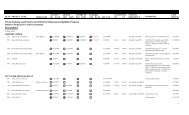
<strong>Monitoring</strong> Data<br />
2006 Flow Data Summary<br />
Storm<br />
Number<br />
Rainfall<br />
(in)<br />
Start Time<br />
End Time<br />
Peak HF<br />
Depth (ft)<br />
Peak VN<br />
Depth (ft)<br />
WQ<br />
Samples?<br />
1 0.31 4/6 555 4/7 941 0.113 0.142 no<br />
2 0.16 4/27 417 4/28 1032 0.028 0.109 no<br />
3 0.09 4/29 2250 5/1 712 0.042 0.125 yes<br />
4 0.11 5/2 1820 5/5 1725 0.025 0.111 yes<br />
5 0.34 5/8 2223 5/10 850 0.154 0.152 yes<br />
6 0.05 5/19 1306 5/20 1625 0.057 0.04 no<br />
7 0.03 5/21 2117 5/22 2211 0.033 0.033 yes<br />
8 0.16 6/7 1324 6/8 1359 0.184 0.121 no<br />
9 0.58 6/23 1833 6/24 2040 0.287 0.323 yes<br />
Extra N/A 7/4 7/4 N/A N/A yes<br />
10 0.08 7/19 1624 7/20 851 0.136 0.129 no<br />
11 0.03 7/22 2156 7/23 2204 0.049 0.046 no<br />
12 0.05 7/24 1956 7/25 902 0.091 0.101 no<br />
13 0.18 8/2 1455 8/3 1450 0.238 0.142 yes<br />
14 0.07 8/4 1716 8/6 303 0.067 0.054 no<br />
15 0.07 8/12 1943 8/13 1953 0.168 0.143 no<br />
16 0.1 8/18 557 8/19 1857 0.106 0.112 no<br />
17 0.05 8/23 1723 8/24 1135 0.119 0.113 no<br />
18 0.15 8/25 639 8/26 1532 0.091 0.121 no<br />
19 0.19 9/6 1710 9/9 1236 0.13 0.161 no<br />
20 0.09 9/10 2036 9/11 2131 0.221 0.122 no<br />
21 0.27 9/20 28 9/21 703 0.144 0.111 yes<br />
22 0.05 9/21 2037 9/22 2049 0.248 0.138 no
UDFCD <strong>BMP</strong> MONITORING SITES<br />
Pervious Concrete Pavement<br />
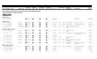
2007 Flow Data Summary<br />
Storm<br />
Number<br />
Rainfall<br />
(in)<br />
Start Time<br />
End Time<br />
Peak HF<br />
Depth (ft)<br />
Peak VN<br />
Depth (ft)<br />
WQ<br />
Samples?<br />
1 0.16 3/30 1229 3/31 1339 0.038 0.01 no<br />
2 0.18 4/8 1559 4/9 1749 0.015 0.033 no<br />
3 0.03 4/10 440 4/10 1205 0.07 0.062 yes<br />
4 0.44 4/16 2313 4/17 1105 0.132 0.127 yes<br />
5 1.31 4/23 1602 4/26 1109 0.147 0.184 yes<br />
6 0.22 5/1 1542 5/2 1642 0.203 0.138 yes<br />
7 0.01 5/7 721 5/8 1856 0.037 0.019 yes<br />
8 0.46 5/14 1856 5/15 1050 0.265 0.121 yes<br />
9 1.03 5/22 1042 5/24 1553 0.235 0.142 yes<br />
10 0.48 5/29 1252 5/30 1235 0.041 0.127 yes<br />
11 0.31 6/12 615 6/13 900 0.234 0.132 yes<br />
12 0.04 7/3 1523 7/4 1550 0.13 0.039 yes<br />
13 0.15 7/8 1502 7/9 1518 0.212 0.124 yes<br />
14 1.02 7/27 1753 7/29 201 0.084 0.217 yes<br />
15 0.43 8/2 302 8/5 2144 0.244 0.159 yes<br />
16 0.32 8/5 2239 8/7 1012 0.167 0.144 yes<br />
17 0.16 8/10 1232 8/10 2233 0.271 0.126 yes<br />
18 0.08 9/24 838 9/25 540 0.184 0.121 yes
UDFCD <strong>BMP</strong> MONITORING SITES<br />
Pervious Concrete Pavement<br />
Other Pervious Concrete Pavement Examples<br />
The following are additional sites in the Denver Metro area that have used<br />
pervious concrete pavement but are not monitored by the <strong>District</strong>. The <strong>District</strong>’s<br />
involvement in the design, construction <strong>and</strong> maintenance of these pervious<br />
concrete pavement sites was either minimal or non-existent, but a photo<br />
inventory of the sites will be kept up-to-date on this website for informational<br />
purposes as to the longevity <strong>and</strong> durability of the pavement.<br />
Safeway<br />
14 th <strong>and</strong> Krameria in Denver<br />
Map this Location<br />
Approximate installation date: January 2005<br />
Installation January 2005<br />
April 2005 (3 months after install)
UDFCD <strong>BMP</strong> MONITORING SITES<br />
Pervious Concrete Pavement<br />
August 2007 Repairs (2 years, 7 months after install)<br />
April/June 2008 (3 years, 5 months after install)
UDFCD <strong>BMP</strong> MONITORING SITES<br />
Pervious Concrete Pavement
UDFCD <strong>BMP</strong> MONITORING SITES<br />
Pervious Concrete Pavement<br />
Wal-Mart<br />
I-70 <strong>and</strong> Tower Road in Aurora<br />
Map this Location<br />
Approximate installation date: 2005<br />
April/June 2008
UDFCD <strong>BMP</strong> MONITORING SITES<br />
Porous Asphalt Pavement<br />
POROUS ASPHALT PAVEMENT<br />
Description Location Typical Details Installation<br />
Photo Gallery <strong>Monitoring</strong> Data Other Examples<br />
Description<br />
General<br />
Porous asphalt pavement may be substituted for conventional<br />
pavement on parking areas <strong>and</strong> areas of light traffic provided the appropriate<br />
grades, subsoil, drainage characteristics <strong>and</strong> groundwater conditions are all<br />
suitable. Porous asphalt consists of an open graded hot mix asphalt that contains<br />
less than 3% of fines passing a #200 U.S. St<strong>and</strong>ard Sieve. The absence of<br />
fines creates permeability. The infiltration bed below the asphalt is<br />
comprised of choker course<br />
aggregate, course aggregate<br />
<strong>and</strong> a s<strong>and</strong> bed. As with any<br />
asphalt pavement installed<br />
in Colorado, the freeze/thaw<br />
cycles <strong>and</strong> the<br />
expansive soils must<br />
be taken into account. It is<br />
recommended that porous asphalt be placed between April <strong>and</strong> October<br />
(when the ambient air temperature is 55 degrees Fahrenheit or greater) with<br />
sufficient base course aggregate, an underdrain trench <strong>and</strong> an impermeable liner<br />
to prevent failure. Proper site evaluation shall take place prior to approval of a<br />
site for porous asphalt application <strong>and</strong> shall include tests for soil permeability,<br />
porosity, depth of seasonal high water table, <strong>and</strong> depth to bedrock. Slopes<br />
should be flat or very gentle <strong>and</strong> shall not exceed 5 percent.<br />
Site Specific<br />
The porous asphalt pavement site monitored by the<br />
<strong>District</strong> is located at the Denver Wastewater Management<br />
Division building. The asphalt was placed in April of 2005 by<br />
companies who donated time <strong>and</strong> materials under the leadership<br />
of the Colorado Asphalt Pavement Association. The design<br />
included 3” of open graded hot mix asphalt <strong>and</strong> 18.5” of #67
UDFCD <strong>BMP</strong> MONITORING SITES<br />
Porous Asphalt Pavement<br />
gravel, #3 gravel <strong>and</strong> C-33 s<strong>and</strong>. In a trench beneath the s<strong>and</strong>, a perforated pipe<br />
collects the filtered water <strong>and</strong> conveys it to a catch basin. There is an orifice<br />
plate at the end of the pipe where a pressure transducer measures the flow into<br />
the catch basin from the porous asphalt pavement. There is<br />
also a weir plate at the outlet of the catch basin with a<br />
levelogger that measures the flow leaving the catch basin.<br />
The difference between the flow passing the orifice plate <strong>and</strong><br />
the flow passing the weir plate is equal to the runoff that<br />
bypassed the porous asphalt pavement <strong>and</strong> entered the catch<br />
basin through the grate.<br />
The sampling equipment is stored in a metal box in the isl<strong>and</strong><br />
adjacent to the porous asphalt pavement. A rain gage on a post<br />
near the storage box measures rainfall <strong>and</strong> signals the ISCO<br />
sampler inside the box to begin sampling after 0.1 inches of rain<br />
falls. The sampler then draws a sample of water from the porous<br />
asphalt pavement runoff after a designated flow has passed, <strong>and</strong><br />
then every 15 minutes until 12 hours after the storm has ended.<br />
There is also a control watershed located a few hundred feet northeast of the<br />
porous asphalt pavement watershed. The control watershed consists primarily of<br />
traditional asphalt pavement <strong>and</strong> is used to compare results of treated runoff to<br />
untreated, direct runoff. Stormwater runoff from the control watershed is collected<br />
in a grated catch basin located in the northeast corner of the parking lot. The<br />
water leaves the catch basin by passing through a weir<br />
plate where a pressure transducer measures the flow.<br />
The sampling equipment is stored in a metal box<br />
adjacent to the parking lot in a manner similar to the<br />
porous asphalt pavement sampling configuration.
UDFCD <strong>BMP</strong> MONITORING SITES<br />
Porous Asphalt Pavement<br />
Test Site Location<br />
The porous asphalt pavement test site is at the Denver Wastewater<br />
Management building located at 2000 W. 3 rd Avenue in Denver. The<br />
pavement is located in the turn-around in front of the building’s main entrance, on<br />
the east side of the isl<strong>and</strong>.<br />
Map this Location<br />
The watershed area tributary to the porous asphalt pavement is 12, 180 square<br />
feet, with the porous asphalt taking up 1840 square feet of that area. The<br />
watershed consists primarily of impervious areas, including buildings, parking lots<br />
<strong>and</strong> paved areas.
UDFCD <strong>BMP</strong> MONITORING SITES<br />
Porous Asphalt Pavement<br />
Typical Details<br />
5.0'<br />
20.0'<br />
92.0'<br />
20.0'<br />
TEMPORARY ORANGE FENCE<br />
POROUS<br />
ASPHALT<br />
25'<br />
18" RCP<br />
@ 1.0%<br />
INLETS:<br />
3.5' x 2.0'<br />
DWMD<br />
BUILDING<br />
CONVENTIONAL<br />
ASPHALT<br />
Porous Asphalt Pavement Plan<br />
AASHTO #67, all fractured<br />
faces; (CDOT SECT. 703-2,<br />
#67 course aggregate)<br />
Open-Graded HMA<br />
ASTM C-33 S<strong>and</strong><br />
Base Course: #3 Aggregate<br />
(CDOT Section 703-2)<br />
2% Min.<br />
18.0" Min.<br />
2.5"<br />
2.0"<br />
7.0"<br />
1.0"<br />
6.0"<br />
Fill under-drain trench<br />
around pipe with<br />
Woven geotextile fabric meeting:<br />
AASHTO #67 stone<br />
ASTM D4751 - AOS U.S. STD. sieve #50 to #70<br />
ASTM D4633 - Min. trapezoidal tear strength 100 X 60 lbs,<br />
Minimum COE specified open area of 4%<br />
6.0"<br />
6.0"<br />
1" Thick s<strong>and</strong><br />
cushion layer<br />
16 mil impermeable liner<br />
under all paved areas<br />
wrapped to top of pavement<br />
Schedule 40 HDPE<br />
4" Under-drain<br />
Porous Asphalt Pavement Section
UDFCD <strong>BMP</strong> MONITORING SITES<br />
Porous Asphalt Pavement<br />
Installation Guidelines<br />
Design Thickness<br />
Asphalt Binder<br />
Design the thickness of the porous<br />
asphalt slab to have a finished<br />
thickness of 2.5 inches with a<br />
bituminous binder of 5.5% to 6.5% by<br />
weight dry aggregate.<br />
Use neat asphalt binder modified with an elastomeric<br />
polymer to produce a binder meeting the requirements of<br />
PG 76022. The elastomeric polymer shall be styrenebutadiene-styrene<br />
(SBS) or approved equivalent, applied<br />
at a rate of 3% by total weight of the binder. The<br />
composite materials shall be thoroughly blended at the<br />
asphalt refinery or terminal prior to being loaded into the<br />
transport vehicle. The polymer-modified asphalt binder<br />
shall be heat <strong>and</strong> storage stable.<br />
Aggregate Gradation Aggregate in the asphalt mix shall be a minimum 90%<br />
crushed material <strong>and</strong> have the following gradation:<br />
U.S. St<strong>and</strong>ard Sieve Size Percent Passing<br />
0.5-inch (12.5 mm) 100<br />
0.375-inch (9.5 mm) 75-95<br />
#4 (4.75 mm) 25-35<br />
#8 (2.36 mm) 10-15<br />
#16 (1.18 mm) 5-10<br />
#30 (600 µm) 1-5<br />
#200 (75 µm) 1-3<br />
Batch Testing<br />
To test draindown, air voids <strong>and</strong> abrasion, prepare<br />
three batches containing asphalt binder contents of<br />
5.5, 6.0 <strong>and</strong> 6.5 percent by dry weight aggregate. The<br />
asphalt content that provides the best results according<br />
to the following table shall be selected as the final mix.<br />
Test the final mix for Moisture Susceptibility <strong>and</strong><br />
Resistance to Stripping. If the final mix does not meet the<br />
requirements for moisture susceptibility <strong>and</strong> resistance to<br />
stripping, add hydrated lime until the requirements are<br />
met.
UDFCD <strong>BMP</strong> MONITORING SITES<br />
Porous Asphalt Pavement<br />
Asphalt Test Requirement Comments<br />
Binder<br />
Downdrain<br />
(ASTM D 6390)<br />
Air Voids of<br />
Compacted Mix<br />
Cantabro<br />
Abrasion Test<br />
(unaged sample)<br />
Moisture<br />
Susceptibility by<br />
the modified<br />
Lottman method<br />
(AASHTO T 283)<br />
Resistance to<br />
Stripping by<br />
Water (ASTM D<br />
3625)<br />
0.3% Maximum Test at 15ºC<br />
higher than<br />
production<br />
temperature<br />
20% Minimum Compact using<br />
50 gyrations of<br />
Superpave<br />
gyratory<br />
compactor<br />
20% Maximum None<br />
80% Minimum<br />
Tensile Strength<br />
Ratio (TSR)<br />
95% Minimum<br />
Coating Area<br />
Only required<br />
for final mix<br />
Only required<br />
for final mix<br />
Choker Course The choker course aggregate shall be AASHTO #67<br />
Aggregate<br />
with all fractured faces. The choker<br />
course aggregate shall have a<br />
uniform thickness of 2 inches.<br />
Base Course<br />
S<strong>and</strong> Layer<br />
The base course aggregate shall be<br />
AASHTO #3 with a uniform<br />
thickness of 7 inches. The base<br />
course aggregate shall rest on top<br />
of a 1-inch thick s<strong>and</strong> cushion<br />
layer in addition to the required s<strong>and</strong> layer <strong>and</strong> on top of<br />
the geotextile fabric.<br />
The bottom s<strong>and</strong> layer shall be ASTM C-33 s<strong>and</strong> <strong>and</strong><br />
will be installed under the base course <strong>and</strong> above the<br />
underdrain trench, when one is used.
UDFCD <strong>BMP</strong> MONITORING SITES<br />
Porous Asphalt Pavement<br />
Geotextile Fabric<br />
The geotextile fabric shall be installed below the s<strong>and</strong><br />
layer. The woven fabric shall conform to the following<br />
requirements:<br />
o ASTM D 4751 – AOS U.S. STD sieve #50 to #70<br />
o ASTM D 4633 – Minimum trapezoidal tear strength<br />
100 x 60 lbs<br />
o Minimum COE specified open area of 4%<br />
Possible geotextile fabric may be US 670, Mirafi<br />
Filterweave 500, or approved equivalent.<br />
Impermeable Liner<br />
Fabric <strong>and</strong> Liner<br />
Contained Cells<br />
When expansive or NRCS Type D soils are present, or<br />
potential for groundwater contamination exists, install a<br />
16 mil impermeable<br />
liner on the bottom <strong>and</strong><br />
sides of all areas to be<br />
paved including the<br />
bottom of the underdrain<br />
trench. The impermeable<br />
liner shall be wrapped to the top of the perimeter walls<br />
<strong>and</strong> attached to the sides securely.<br />
If soils are not expansive (NRCS Types A, B or C) use<br />
woven geotextile fabric (as described above) as a liner.<br />
Place fabric <strong>and</strong> liner by rolling parallel to the contours<br />
starting at the most downstream part of the pavement.<br />
Provide a minimum of 18” overlap between adjacent<br />
sheets. Bring up geotextile fabric <strong>and</strong> impermeable liner<br />
to the top of the perimeter walls <strong>and</strong> attach with roofing<br />
tar or other adhesive or concrete anchors. Provide<br />
sufficient slack in the geotextile fabric <strong>and</strong> impermeable<br />
liner to prevent stretching during the installation of the<br />
infiltration bed, choker course <strong>and</strong> wearing course<br />
aggregate. Seal all joints of the impermeable liner to be<br />
totally leak free.<br />
Install lateral flow cut-off barriers using 16 mil or<br />
thicker PE or PVC membrane liner or concrete walls<br />
installed parallel to the contours (i.e. normal to the flow)<br />
to prevent flow of water downstream <strong>and</strong> then surfacing<br />
at the toe of the porous asphalt pavement installation.<br />
Distance (L max ) between these cut-off barriers shall not<br />
exceed:
UDFCD <strong>BMP</strong> MONITORING SITES<br />
Porous Asphalt Pavement<br />
D<br />
L max = 1. 5∗ So<br />
◊ Lmax = maximum distance between cut-off<br />
membrane normal to the flow (ft)<br />
◊ So = slope of the base course (ft/ft)<br />
◊ D = depth of gravel base course (ft)<br />
Subdrain System<br />
When the porous asphalt pavement is located on NRCS<br />
Type D soils, when the Type B or C soil sub-base is to be<br />
compacted for structural reasons, or when an<br />
impermeable membrane liner is needed, install a<br />
subdrain system using perforated HDPE pipe.<br />
Locate each perforated pipe just upstream of the lateralflow<br />
cut-off barrier. Do not exceed 20-foot spacing. Use a<br />
control orifice sized to drain the pore volume of empty<br />
each cell in 6 hours or more.<br />
Design Area Ratio The design area ratio shall not exceed 2.0 (ratio =<br />
And Effective contributing impervious area/porous pavement area). The<br />
Imperviousness interim recommendations for the effective<br />
imperviousness are given in the Manual.
UDFCD <strong>BMP</strong> MONITORING SITES<br />
Porous Asphalt Pavement<br />
Photo Gallery<br />
Installation Photos – April 2008<br />
Site demo Excavated pit Coring into the catch basin<br />
Placing the #3 aggregate Layer of #67 aggregate Looking south<br />
Looking north <strong>Monitoring</strong> equipment box Porous vs. traditional asphalt<br />
ISCO Samplers Rain gage Rain gage mechanism
UDFCD <strong>BMP</strong> MONITORING SITES<br />
Porous Asphalt Pavement<br />
Performance Check – July 2008 (3 months after install)<br />
Denver Public Works supplied Water dispensed from truck Flow over asphalt<br />
the water<br />
Outlet weir in catch basin Flow through orifice plate Equipment in catch basin
UDFCD <strong>BMP</strong> MONITORING SITES<br />
Porous Asphalt Pavement<br />
<strong>Monitoring</strong> Data<br />
2008 Flow Data<br />
2008 Water Quality Data
UDFCD <strong>BMP</strong> MONITORING SITES<br />
Porous Asphalt Pavement<br />
Other Porous Asphalt Pavement Examples<br />
The following are additional sites in the Denver Metro area that have used<br />
porous asphalt pavement but are not monitored by the <strong>District</strong>. The<br />
<strong>District</strong>’s involvement in the design, construction <strong>and</strong> maintenance of these<br />
porous asphalt pavement sites was either minimal or non-existent, but a photo<br />
inventory of the sites will be kept up-to-date on this website for informational<br />
purposes as to the longevity <strong>and</strong> durability of the pavement.<br />
Wal-Mart<br />
I-70 <strong>and</strong> Tower Road in Aurora<br />
Map this Location<br />
Approximate installation date: 2005<br />
April/June 2008 (3 years after install)
UDFCD <strong>BMP</strong> MONITORING SITES<br />
Permeable Interlocking Concrete Pavement<br />
PERMEABLE INTERLOCKING<br />
CONCRETE PAVEMENT<br />
Description Location Typical Details Installation<br />
Photo Gallery <strong>Monitoring</strong> Data Other Examples<br />
Description<br />
General<br />
Permeable interlocking concrete pavement (PICP) consists of concrete block<br />
units with open surface voids laid on a gravel subgrade. These voids occupy<br />
at least 20% of the total surface area that are filled<br />
with s<strong>and</strong> or s<strong>and</strong>y loam turf that has at least 50%<br />
s<strong>and</strong> by weight in its volume. However, unless the<br />
pavement will be watered regularly (i.e., using a<br />
sprinkler system) to keep the vegetation viable,<br />
concrete s<strong>and</strong> infill is the recommended<br />
material. Permeable interlocking concrete<br />
pavement may be sloped or flat. PICPs<br />
have been in use in the United States since<br />
the mid-1970s. Although field data that<br />
quantify their long-term performance are somewhat limited, the data<br />
collected locally, <strong>and</strong> at other parts or the country <strong>and</strong> the episodic<br />
reports from Canada, Australia, Asia <strong>and</strong> Europe indicate that properly<br />
installed PICP are reliable <strong>and</strong> have experienced few problems under a<br />
wide range of climates. An alternate application of PICP provides for a<br />
surcharge zone above its surface to detain runoff <strong>and</strong> provide storage<br />
space for the water quality capture volume.<br />
Site Specific<br />
The permeable interlocking concrete pavement site monitored<br />
by the <strong>District</strong> is located at the Denver Wastewater<br />
Management Division building. The PICP was placed<br />
in May of 2005 by Rocky Mountain Hardscapes. The design<br />
included a 3 1/8” paver on top of 16 inches of #8 gravel, #67
UDFCD <strong>BMP</strong> MONITORING SITES<br />
Permeable Interlocking Concrete Pavement<br />
gravel <strong>and</strong> C-33 s<strong>and</strong>. In a trench beneath the s<strong>and</strong>, a perforated<br />
pipe collects the filtered water <strong>and</strong> conveys it to a catch basin.<br />
There is an orifice plate at the end of the pipe where a pressure<br />
transducer measures the flow into the catch basin from the PICP.<br />
There is also a weir plate at the outlet of the catch basin with a<br />
levelogger that measures the flow leaving the catch basin. The difference<br />
between the flow passing the orifice plate <strong>and</strong> the flow passing the weir<br />
plate is equal to the runoff that bypassed the PICP <strong>and</strong> entered the<br />
catch basin through the grate.<br />
The sampling equipment is stored in a metal box in the isl<strong>and</strong> adjacent<br />
to the PICP. A rain gage on a post near the storage box measures<br />
rainfall <strong>and</strong> signals the ISCO sampler inside the box to begin sampling<br />
after 0.1 inches of rain falls. The sampler then draws a sample of water<br />
from the PICP runoff after a designated flow has passed, <strong>and</strong> then<br />
every 15 minutes until 12 hours after the storm has ended.<br />
There is also a control watershed located a few hundred feet northeast of the<br />
PICP watershed. The control watershed consists primarily of traditional asphalt<br />
pavement <strong>and</strong> is used to compare results of treated runoff to untreated, direct<br />
runoff. Stormwater runoff from the control watershed is collected in a grated<br />
catch basin located in the northeast corner of the parking lot. The water leaves<br />
the catch basin by passing through a weir plate where a pressure transducer<br />
measures the flow. The sampling equipment is stored<br />
in a metal box adjacent to the parking lot in a manner<br />
similar to the PICP sampling configuration.
UDFCD <strong>BMP</strong> MONITORING SITES<br />
Permeable Interlocking Concrete Pavement<br />
Test Site Location<br />
The permeable interlocking concrete pavement test site is at the Denver<br />
Wastewater Management building located at 2000 W. 3 rd Avenue in Denver.<br />
The pavement is located in the turn-around in front of the building’s main<br />
entrance, on the west side of the isl<strong>and</strong>.<br />
Map this Location<br />
The watershed area tributary to the PICP is xxxx square feet, with the pavers<br />
taking up 1840 square feet of that area. The site consists primarily of impervious<br />
areas, including buildings, parking lots <strong>and</strong> paved areas.
UDFCD <strong>BMP</strong> MONITORING SITES<br />
Permeable Interlocking Concrete Pavement<br />
Typical Details<br />
18" RCP<br />
@ 1.0%<br />
25'<br />
SAMPLING<br />
EQUIPMENT BOX<br />
CONDUIT<br />
INLETS:<br />
3.5' x 2.0'<br />
TRADITIONAL<br />
ASPHALT<br />
PAVEMENT<br />
20.0'<br />
5.0'<br />
20.0'<br />
TEMPORARY ORANGE FENCE<br />
92.0'<br />
COBBLESTONE<br />
BLOCK<br />
PAVEMENT<br />
Permeable Interlocking Concrete Pavement Plan<br />
Base Course: AASHTO #67, all fractured faces;<br />
(CDOT SECT. 703, #67 course aggregate)<br />
In-fill <strong>and</strong> leveling course: AASHTO crushed #8 (CDOT<br />
sect. 703, #8 course aggregate), all fractured faces<br />
Cobblestone blocks with at<br />
least 8% surface area open<br />
3.125"<br />
2.0"<br />
7.0"<br />
1.0"<br />
6.0"<br />
Wrap all geotextile<br />
fabric <strong>and</strong> impermeable<br />
liner to top of cobble<br />
block. Attach to wall or<br />
side of trench securely.<br />
1" Thick s<strong>and</strong><br />
cushion layer<br />
Note: Extend<br />
geotextile fabric<br />
<strong>and</strong> minimum of<br />
18" beyond trench<br />
Woven geotextile fabric meeting:<br />
ASTM D4751 - AOS U.S. STD. sieve #50 to #70<br />
ASTM D4633 - Min. trapezoidal tear strength 100 X 60 lbs,<br />
Minimum COE specified open area of 4%<br />
Fill under-drain trench<br />
around pipe with<br />
AASHTO #67 stone<br />
Schedule 40 HDPE<br />
Perforated 4" Under-drain<br />
16 mil impermeable liner<br />
under all pavement wrapped<br />
to top of pavement<br />
ASTM C-33 S<strong>and</strong><br />
Permeable Interlocking Concrete Pavement Section
UDFCD <strong>BMP</strong> MONITORING SITES<br />
Permeable Interlocking Concrete Pavement<br />
Installation Guidelines<br />
Select Blocks Select PICP blocks that have 8%<br />
open area or more. Follow<br />
manufacturer’s installation<br />
instructions, except that infill <strong>and</strong><br />
base course materials <strong>and</strong><br />
dimensions specified in this section shall be strictly<br />
adhered to.<br />
Infill Materials <strong>and</strong> The PICP openings shall be filled with AASHTO #8<br />
Leveling Course fractured aggregate <strong>and</strong> shall be placed on a one-inch<br />
thick leveling course of same #8 aggregate.<br />
Base Course<br />
The base course shall be AASHTO #67 coarse<br />
aggregate; all fractured surfaces. For volume<br />
calculations assume 30% of total volume to be<br />
open pore space. Unless an underdrain is<br />
provided, at least 6 inches of the subgrade<br />
underlying the base course shall be s<strong>and</strong>y <strong>and</strong><br />
gravelly material with no more than 10% clay<br />
fraction.<br />
S<strong>and</strong> Filter Layer The s<strong>and</strong> filter layer shall be ASTM C-33<br />
s<strong>and</strong> <strong>and</strong> will be installed under the base<br />
course <strong>and</strong> above the underdrain trench<br />
when one is used.<br />
Geotextile Fabric<br />
Place a woven geotextile fabric on top <strong>and</strong> bottom<br />
of the base course. Use a geotextile material that meets<br />
the following requirements:<br />
o ASTM D-4751 – AOS U.S. Std. Sieve #50 to #70<br />
o D-4633 – Trapezoidal tear strength ≥ 100 x 60 lbs<br />
o COE specified minimum open area ≥ 4%<br />
Impermeable Liner<br />
When expansive or NRCS Type D soils are present, or<br />
potential for groundwater contamination exists, install a<br />
16 mil thick impermeable liner on the bottom <strong>and</strong><br />
sides of the basin under the pavement. If soils are not<br />
expansive (i.e. NRCS Type A, B or C), use a woven<br />
geotextile material that meets the requirements specified
UDFCD <strong>BMP</strong> MONITORING SITES<br />
Permeable Interlocking Concrete Pavement<br />
under Geotextile Fabric above. Products that meet these<br />
requirements are:<br />
o US Fabric US 2070 <strong>and</strong> US 670<br />
o Mirafi Filterweave 500 <strong>and</strong> 700<br />
o Carthage Mills Carthage 6%.<br />
Fabric/Liner<br />
Installation<br />
Place by rolling fabric parallel to the contours starting at<br />
the most downstream part of the pavement. Provide a<br />
minimum of 18” overlap between adjacent sheets.<br />
Bring up geotextile <strong>and</strong> impermeable membrane to the<br />
top of perimeter walls. Attach membrane <strong>and</strong><br />
fabric to perimeter walls with roofing tar or<br />
other adhesive or concrete anchors. Provide<br />
sufficient slack in the geotextile <strong>and</strong><br />
membranes to prevent stretching them when<br />
s<strong>and</strong> <strong>and</strong>/or rock is placed. Seal all joints of<br />
impermeable membrane to be totally leak free.<br />
Perimeter Wall<br />
Recommend that a concrete perimeter wall<br />
be installed to confine the edges of the PICP<br />
block areas.<br />
Contained Cells<br />
Install lateral flow cut-off barriers using 16 mil or<br />
thicker PE or PVC membrane liner or concrete walls<br />
installed parallel to the contours (i.e. normal to the flow)<br />
to prevent flow of water downstream <strong>and</strong> then surfacing<br />
at the toe of the PICP installation. Distance (Lmax)<br />
between these cut-off barriers shall not exceed:<br />
L max<br />
= 1. 5∗<br />
D<br />
So<br />
o Lmax = maximum distance between cut-off membrane<br />
normal to the flow (ft)<br />
o So = slope of the base course (ft/ft)<br />
o D = depth of gravel base course (ft)<br />
Subdrain System<br />
When the PICP is located on NRCS Type D soils, when<br />
the Type B or C soil sub-base is to be<br />
compacted for structural reasons, or<br />
when an impermeable membrane<br />
liner is needed, install a subdrain
UDFCD <strong>BMP</strong> MONITORING SITES<br />
Permeable Interlocking Concrete Pavement<br />
system using perforated HDPE pipe. Locate each<br />
perforated pipe just upstream of the lateral-flow cut-off<br />
barrier. Do not exceed 20-foot spacing. Use a control<br />
orifice sized to drain the pore volume of empty each cell<br />
in 6 hours or more.<br />
Design Area Ratio The design area ratio shall not exceed 2.0 (ratio =<br />
And Effective contributing impervious area/pervious pavement area).<br />
Imperviousness The interim recommendations for the Effective<br />
Imperviousness are provided in the Manual.
UDFCD <strong>BMP</strong> MONITORING SITES<br />
Permeable Interlocking Concrete Pavement<br />
Photo Gallery<br />
Installation Photos – May 2005<br />
Before construction Excavated pit with concrete Sampling tube conduit<br />
perimeter wall<br />
#67 aggregate ASTM C-33 s<strong>and</strong> Placing the s<strong>and</strong> layer<br />
Permeable interlocking One unit of paver Placing the pavers<br />
concrete pavers<br />
Finished pavement
UDFCD <strong>BMP</strong> MONITORING SITES<br />
Permeable Interlocking Concrete Pavement<br />
Performance Check – July 2008 (2 months after install)<br />
Denver Public Works supplied Water dispensed from truck Flow over asphalt<br />
the water<br />
Water never reached gutter Flow through orifice plate Outlet weir in catch basin<br />
Equipment in catch basin
UDFCD <strong>BMP</strong> MONITORING SITES<br />
Permeable Interlocking Concrete Pavement<br />
<strong>Monitoring</strong> Data<br />
2008 Flow Data<br />
2008 Water Quality Data
UDFCD <strong>BMP</strong> MONITORING SITES<br />
Permeable Interlocking Concrete Pavement<br />
Other Permeable Interlocking Concrete Pavement<br />
Examples<br />
The following are additional sites in the Denver Metro area that have used<br />
permeable interlocking concrete pavement but are not monitored by the<br />
<strong>District</strong>. The <strong>District</strong>’s involvement in the design, construction <strong>and</strong> maintenance<br />
of these PICP sites was either minimal or absent, but a photo inventory of the<br />
sites will be kept up-to-date on this website for informational purposes as to the<br />
longevity <strong>and</strong> durability of the pavement.<br />
Wenk Associates<br />
1335 Elati Street in Denver<br />
Map this Location<br />
Approximate installation date: April 2004<br />
Installation Photos - April 2004
UDFCD <strong>BMP</strong> MONITORING SITES<br />
Permeable Interlocking Concrete Pavement<br />
August 2004 (4 months after install)<br />
April 2005 (1 year after install)<br />
June 2008 (4 years, 2 months after install)
UDFCD <strong>BMP</strong> MONITORING SITES<br />
Permeable Interlocking Concrete Pavement
UDFCD <strong>BMP</strong> MONITORING SITES<br />
S<strong>and</strong> Filters<br />
SAND FILTERS<br />
A s<strong>and</strong> filter extended detention basin is a stormwater filter that consists of a<br />
runoff storage zone underlain by a s<strong>and</strong> bed with an underdrain system.<br />
During a storm, accumulated runoff ponds in the<br />
surcharge zone <strong>and</strong> gradually infiltrates into the<br />
underlying s<strong>and</strong> bed, filling the void spaces of the s<strong>and</strong>.<br />
The underdrain gradually dewaters the s<strong>and</strong> bed <strong>and</strong><br />
discharges the runoff to a nearby channel, swale or storm<br />
sewer.<br />
A s<strong>and</strong> filter is generally suited to onsite configurations<br />
where there is no base flow <strong>and</strong> is put in operation<br />
when the upstream catchment no longer has construction<br />
or grading/l<strong>and</strong>scaping activities.<br />
Primary advantages of s<strong>and</strong> filters include effective water quality enhancement<br />
through settling <strong>and</strong> filtering. The primary disadvantage is a potential for<br />
clogging if a moderate to high level of silts <strong>and</strong> clays are<br />
allowed to flow into the facility. For this reason, the s<strong>and</strong> filter<br />
should not be put into operation while construction or major<br />
l<strong>and</strong>scaping activities are taking place in the tributary catchment.<br />
Also, this <strong>BMP</strong> should not be located close to building<br />
foundations or other areas where expansive soils are a concern,<br />
although an underdrain <strong>and</strong> impermeable line can ameliorate<br />
some of this concern.<br />
Since an underdrain system is incorporated into this <strong>BMP</strong>, s<strong>and</strong> filters are<br />
suitable for about any site; presence of s<strong>and</strong>y subsoil is not a requirement. This<br />
<strong>BMP</strong> has a flat surface area, so it may be more challenging to incorporate it into<br />
steeply sloping terrain.<br />
S<strong>and</strong> Filters Monitored by <strong>District</strong>
UDFCD <strong>BMP</strong> MONITORING SITES<br />
Open Bed S<strong>and</strong> Filter<br />
OPEN BED SAND FILTER<br />
Description Location Typical Details Installation<br />
Photo Gallery <strong>Monitoring</strong> Data Other Examples<br />
Description<br />
The open bed s<strong>and</strong> filter that is monitored for flow volume<br />
<strong>and</strong> water quality by the <strong>District</strong> is located in Lakewood <strong>and</strong><br />
was constructed in March/April of 2007. The vault is<br />
made of reinforced concrete with two cells separated by a<br />
concrete wall. The s<strong>and</strong> filter cell is 100’ long by 5’ wide by<br />
4’-4.5’ deep. The outlet cell is 4’ long by 5’ wide by 5’ deep.<br />
The s<strong>and</strong> filter cell contains a 15”-18” layer of s<strong>and</strong>, a nonwoven<br />
geotextile fabric, <strong>and</strong> a 5”-8” layer of aggregate.<br />
At the bottom of the s<strong>and</strong> filter cell there is a 4” perforated underdrain pipe<br />
that collects the filtered water <strong>and</strong> carries it to the outlet cell. An orifice plate with<br />
a 5/8” hole controls the outflow under regular flow conditions <strong>and</strong> a sharp-crested<br />
weir at the top of the wall separating the cells controls flow under high flow<br />
conditions. Pressure transducers located in the middle <strong>and</strong> at the end of the s<strong>and</strong><br />
filter cell measure water depths.<br />
The sampling equipment for the inlet is stored in a wooden<br />
box near the upstream end of the s<strong>and</strong> filter <strong>and</strong> the equipment for<br />
the outlet is stored in a shed adjacent to the outlet of the s<strong>and</strong><br />
filter. A rain gage on top of the shed measures rainfall <strong>and</strong><br />
signals the ISCO samplers inside the box <strong>and</strong> the shed to begin<br />
sampling after 0.1 inches of rain falls. The samplers then draw a<br />
sample of water from the inlet <strong>and</strong> outlet after a designated<br />
amount of flow has passed, <strong>and</strong> then every 15 minutes until 12<br />
hours after the storm has ended.<br />
The total cost to construct the open bed s<strong>and</strong> filter was $74,000 in 2007. The<br />
costs included reinforced concrete, reinforced concrete pipe, removal <strong>and</strong><br />
replacement of asphalt, earthwork, curb <strong>and</strong> gutter, geotextile, C-33 s<strong>and</strong>, #67<br />
aggregate, grating, orifice <strong>and</strong> weir plates, <strong>and</strong> perforated pipe.
UDFCD <strong>BMP</strong> MONITORING SITES<br />
Open Bed S<strong>and</strong> Filter<br />
Updates<br />
At the end of the first storm season, the s<strong>and</strong> filter was not<br />
draining properly. In the spring of 2008 the water in the<br />
s<strong>and</strong> filter was pumped out <strong>and</strong> the top layer of s<strong>and</strong> was<br />
scraped off. By July of 2008 the s<strong>and</strong> filter was again not draining. The pumping<br />
<strong>and</strong> scraping process was repeated.<br />
In the spring of 2008 the sharp-crested weir was replaced<br />
with a Cipoletti weir <strong>and</strong> lowered to the correct height.<br />
In 2008, a Cipoletti weir was added to the catch basin at the opening of the pipe<br />
that conveys flows captured in the catch basin to the<br />
s<strong>and</strong> filter. The intent of the weir is to allow a means to<br />
measure the amount of flow into the s<strong>and</strong> filter. A<br />
pressure transducer was also placed in the catch basin<br />
to measure the depth of flow over the weir.
UDFCD <strong>BMP</strong> MONITORING SITES<br />
Open Bed S<strong>and</strong> Filter<br />
Test Site Location<br />
The open bed s<strong>and</strong> filter test site is on the City of Lakewood maintenance<br />
buildings property located at 1050 Quail Street. The site consists primarily of<br />
impervious areas used for maintenance <strong>and</strong> storage of vehicles <strong>and</strong> equipment.<br />
Map this Location<br />
The watershed area tributary to the s<strong>and</strong> filter is approximately 6,000 square feet<br />
(0.15 acres). The site contains a car wash which is regularly used, so many<br />
contaminants (oil, soap, etc.) drain into the s<strong>and</strong> filter.
UDFCD <strong>BMP</strong> MONITORING SITES<br />
Open Bed S<strong>and</strong> Filter
UDFCD <strong>BMP</strong> MONITORING SITES<br />
Open Bed S<strong>and</strong> Filter<br />
Typical Details<br />
Catch Basin<br />
S<strong>and</strong> Filter Inlet<br />
Orifice Plate<br />
S<strong>and</strong> Filter Cell<br />
Outfall to Stream<br />
100'<br />
Outlet Cell<br />
106'<br />
Open Bed S<strong>and</strong> Filter Plan<br />
2-1/2" Dia<br />
x5" deep sleeve<br />
for fence post<br />
49" 13,5"<br />
2-1/2" Dia<br />
x5" deep sleeve<br />
for fence post<br />
49" 13,5"<br />
8"<br />
8"<br />
67"<br />
6"<br />
8"<br />
8"<br />
12"<br />
43"<br />
60"<br />
76"<br />
12" 8" 18"<br />
29"<br />
WATER LINE<br />
9.0'-10.5'<br />
FROM BACK<br />
OF CURB<br />
3.7' APPROX.<br />
DEPTH<br />
73"<br />
43"<br />
60"<br />
12" 8" 18"<br />
35"<br />
WATER LINE<br />
9.0'-10.5'<br />
FROM BACK<br />
OF CURB<br />
3.7' APPROX.<br />
DEPTH<br />
76"<br />
Upstream End<br />
Downstream End<br />
Open Bed S<strong>and</strong> Filter Cross Sections
UDFCD <strong>BMP</strong> MONITORING SITES<br />
Open Bed S<strong>and</strong> Filter<br />
Installation Guidelines<br />
Basin Storage Volume Provide a storage volume equal to 100 percent of the<br />
WQCV based on a 40-hour drain time, above the<br />
s<strong>and</strong> bed of the basin.<br />
A. Determine the WQCV tributary catchment’s percent<br />
imperviousness. Account for the effects of DCIA or<br />
other runoff volume reducing facilities, if any, in the<br />
tributary catchments.<br />
B. Find the required storage volume (watershed inches<br />
of runoff): Determine the Required WQCV (watershed<br />
inches of runoff) based on a 40-hour drain time.<br />
C. Calculate the Design Volume in acre-feet as follows:<br />
⎛WQCV<br />
⎞<br />
DesignVolu me = ⎜ ⎟ * Area<br />
⎝ 12 ⎠<br />
In which:<br />
Area = Area tributary to the s<strong>and</strong> filter<br />
Basin Depth/Design<br />
Filter’s Surface Area<br />
Maximum depth for the Design Volume shall be 3 feet.<br />
Calculate the minimum s<strong>and</strong> filter area (As) of the basin’s<br />
bottom using:<br />
⎛ DesignVolume ⎞<br />
As = ⎜<br />
⎟ * 43,560 (square feet)<br />
⎝ 3 ⎠<br />
S<strong>and</strong> Media<br />
Provide, as a minimum, an 18-inch<br />
layer of C-33 s<strong>and</strong>. Keep the top<br />
surface flat. If side slopes need to be<br />
steeper than 3h:1v (4h:1v or flatter is<br />
preferred), use vertical walls.<br />
Granular Base <strong>and</strong><br />
Underdrains<br />
Granular material shall have all fractured<br />
faces <strong>and</strong> meet the technical requirements of AASHTO<br />
#3, #4 or #67 aggregate.
UDFCD <strong>BMP</strong> MONITORING SITES<br />
Open Bed S<strong>and</strong> Filter<br />
Impermeable<br />
Membrane <strong>and</strong><br />
Geotextile Liners<br />
When expansive or NRCS Type D soils are present, or<br />
when st<strong>and</strong>ard percolation tests show percolation<br />
drawdown rates exceeding 60 minutes per inch, or<br />
potential for groundwater contamination exists, install a<br />
16 mil thick impermeable liner on the bottom <strong>and</strong><br />
sides of the basin. If vertical walls are permeable or of<br />
stacked blocks, extend the impermeable liner behind the<br />
walls.<br />
If soils are not expansive (i.e., NRCS Type A, B or C),<br />
use a woven geotextile material that meets the<br />
following ASTM requirements:<br />
o D-4751 – AOS U.S. Std. Sieve #50 to #70<br />
o D-4633 – Trapezoidal tear strength >= 100x60 lbs<br />
o COE specified open area >= 4%.<br />
Products meeting requirements: US Fabric US 2070 <strong>and</strong><br />
US 670, Mirafi Filterweave 500 <strong>and</strong> 700, Carthage Mills<br />
Carthage 6%.<br />
Wrap all liners to top of the s<strong>and</strong> filter basin <strong>and</strong> attach<br />
firmly with staples to the soil vertical wall using staples or<br />
concrete anchors. Provide sufficient slack so that the<br />
liners are not stretched when rock <strong>and</strong> s<strong>and</strong>/peat mix is<br />
placed. If tears are seen or discovered, repair them as<br />
recommended by manufacturer with no less than 18<br />
inches of overlap on all sides of the tear.<br />
Outlet Works<br />
When underdrains are needed, the outlet<br />
works consists of 4” perforated HDPE<br />
pipe to convey water to the overflow outlet<br />
structure. Space perforated pipe on 20 foot<br />
centers or less. At the outlet of the HDPE<br />
pipe into the box, install an orifice sized to<br />
empty the WQCV above the s<strong>and</strong> in no less<br />
than 24 hours.<br />
Provided an overflow outlet pipe out of the<br />
overflow structure to convey flows away from<br />
the filter basin when the runoff volume exceeds<br />
the WQCV at rates required by local<br />
jurisdiction to control the flood detention,<br />
typically the 10- <strong>and</strong> the 100-year storm.
UDFCD <strong>BMP</strong> MONITORING SITES<br />
Open Bed S<strong>and</strong> Filter<br />
The WQCV basin may be oversized to contain the<br />
EURV, in which case design the orifice outlet to drain the<br />
EURV in 72 hours <strong>and</strong> control the 100-year volume as<br />
described in the Manual.<br />
Inlet Works<br />
Provide an energy dissipating outlet for all inlet<br />
points into the s<strong>and</strong> filter. Use an impact basin for pipes<br />
<strong>and</strong> a baffle chute or grouted sloping boulder drop if a<br />
channel or swale is used. Install a Type VL or L riprap<br />
basin at the inlet over a geotextile fabric that is wrapped<br />
up on the sides to the top of the s<strong>and</strong> layer. Fill all rock<br />
voids with filter s<strong>and</strong>.
UDFCD <strong>BMP</strong> MONITORING SITES<br />
Open Bed S<strong>and</strong> Filter<br />
Photo Gallery<br />
Installation Photos (March/April 2007)<br />
Pre-construction site Concrete walls Finished s<strong>and</strong> filter<br />
During a storm Inlet sampling equipment Outlet sampling equipment<br />
Sharp-crested overflow weir Concrete wall separating cells Flow over weir<br />
Flow through outlet orifice Sampling tube at outlet Inflow vs. outflow samples
UDFCD <strong>BMP</strong> MONITORING SITES<br />
Open Bed S<strong>and</strong> Filter<br />
September 2007 (5 months after install)<br />
Outlet cell<br />
Debris in overflow weir<br />
June 2008 (1 year, 2 months after install)<br />
New Cipoletti overflow weir Installing the weir Catch basin at inlet<br />
New Cipoletti weir in inlet<br />
catch basin<br />
July 2008 (1 year, 3 months after install)<br />
Lubri-seal in s<strong>and</strong> filter Outflow to stream S<strong>and</strong> filter not draining
UDFCD <strong>BMP</strong> MONITORING SITES<br />
Open Bed S<strong>and</strong> Filter<br />
<strong>Monitoring</strong> Data<br />
2008 Flow Data<br />
2008 Water Quality Data<br />
2007 Flow Data<br />
Storm<br />
Number<br />
Rainfall<br />
(in)<br />
Start Time<br />
End Time<br />
Peak Outlet<br />
Depth (ft)<br />
Samples<br />
1 N/A 6/11/07 6:18 6/12/07 9:29 1.019 No<br />
3 N/A 7/2/07 15:22 7/3/07 15:52 N/A Yes<br />
2 N/A 7/7/07 15:01 7/8/07 14:30 0.693 Yes<br />
3 N/A<br />
7/31/07<br />
20:15<br />
4 N/A 8/9/07 13:54<br />
5 N/A<br />
8/13/07<br />
19:34<br />
6 0.08 9/23/07 8:38<br />
8/6/07 10:46 1.44 Yes<br />
8/12/07<br />
12:39<br />
8/15/07<br />
11:02<br />
9/24/07<br />
11:58<br />
0.19 No<br />
0.398 Yes<br />
0.153 No<br />
2007 Water Quality Data
UDFCD <strong>BMP</strong> MONITORING SITES<br />
Open Bed S<strong>and</strong> Filter<br />
Other S<strong>and</strong> Filter Examples<br />
The following are additional sites in the Denver Metro area that have used s<strong>and</strong><br />
filters but are not monitored by the <strong>District</strong>. The <strong>District</strong>’s involvement in<br />
the design, construction <strong>and</strong> maintenance of these s<strong>and</strong> filter sites was either<br />
minimal or non-existent, but a photo inventory of the sites will be kept up-to-date<br />
on this website for informational purposes as to the longevity <strong>and</strong> durability of the<br />
s<strong>and</strong> filter.
UDFCD <strong>BMP</strong> MONITORING SITES<br />
Extended Detention Basins<br />
EXTENDED DETENTION BASINS<br />
An extended detention basin is a sedimentation basin designed to totally<br />
drain dry sometime after stormwater runoff ends. It is an adaptation of a<br />
detention basin used for flood control. The primary difference is the<br />
outlet design: the extended detention basin uses a much smaller<br />
outlet that extends the emptying time of the more frequently<br />
occurring runoff events to facilitate pollutant removal. The extended<br />
detention basin’s 40-hour drain time for the brim-full water<br />
quality capture volume is recommended to remove a significant<br />
portion of fine particulate pollutants found in urban stormwater<br />
runoff. Soluble pollutant removal can be somewhat enhanced by<br />
providing a small wetl<strong>and</strong> marsh or ponding area in the basin’s bottom to<br />
promote biological uptake. The basins are considered to be “dry” because they<br />
are designed not to have a significant permanent pool of water remaining<br />
between storm runoff events. However, extended detention basins may<br />
develop wetl<strong>and</strong> vegetation <strong>and</strong> sometimes shallow pools in the bottom<br />
portions of the facilities.<br />
An extended detention basin can be used to enhance<br />
stormwater runoff quality <strong>and</strong> reduce peak<br />
stormwater runoff rates. If these basins are<br />
constructed early in the development cycle, they can also<br />
be used to trap sediment from construction activities<br />
within the tributary drainage area. The accumulated<br />
sediment, however, will need to be removed after<br />
upstream l<strong>and</strong> disturbances cease <strong>and</strong> before the basin<br />
is placed into final long-term use. An extended detention basin can sometimes be<br />
retrofitted into existing flood control detention basins.<br />
Extended detention basins can be used to improve the quality of urban runoff<br />
<strong>and</strong> are generally used for regional or follow-up treatment. Extended detention<br />
basins are most applicable for catchments with a tributary impervious area of 10<br />
acres or more.<br />
Extended Detention Basins Monitored by <strong>District</strong>
UDFCD <strong>BMP</strong> MONITORING SITES<br />
Orchard Pond EDB<br />
ORCHARD POND EDB<br />
Description Location Typical Details Installation<br />
Photo Gallery <strong>Monitoring</strong> Data Other Examples<br />
Description<br />
The Orchard Pond extended detention basin, located at Grant Ranch in<br />
Denver, was constructed in 1998 by the Bowles Metropolitan <strong>District</strong>. The <strong>District</strong><br />
has been collecting water quality <strong>and</strong> flow data from the pond since 2004.<br />
By studying the design of the basin <strong>and</strong> the parameters of the watershed, the<br />
statistical data will be used to develop relationships between the tributary<br />
catchment characteristics, the extended detention basin design parameters <strong>and</strong><br />
their effects on water quality. With the results from the monitoring, we are able to<br />
determine how effectively the basin stores different stormwater volumes <strong>and</strong> to<br />
study the hydraulic functioning of the outlet structure.
UDFCD <strong>BMP</strong> MONITORING SITES<br />
Orchard Pond EDB<br />
Since the initial construction, the following modifications have been made to<br />
improve the facility:<br />
o In 2004, a micropool was<br />
incorporated into the basin <strong>and</strong> the<br />
outlet structure was improved with<br />
a perforated plate.<br />
o In 2005, the inlet structure was<br />
modified with an improved<br />
forebay <strong>and</strong> an energy dissipater<br />
in order to improve sedimentation.<br />
Orchard Pond is directly upstream of Bowles Lake, a large facility used for<br />
recreation, fishing <strong>and</strong> boating. Therefore it is important to protect these waters<br />
from metals, oil, grease <strong>and</strong> sediment that is typically found in urban stormwater<br />
runoff.<br />
UDFCD has been collecting water quality <strong>and</strong> flow data at this site since 2004.<br />
Wright Water Engineers is responsible for running <strong>and</strong> maintaining the<br />
sampling equipment <strong>and</strong> taking the samples to the lab after a storm.
UDFCD <strong>BMP</strong> MONITORING SITES<br />
Orchard Pond EDB<br />
Test Site Location<br />
The Orchard Pond extended detention basin is located in the northeast corner of<br />
the Grant Ranch residential development in Denver. Specifically, the basin lies<br />
between South Harlan Way <strong>and</strong> West Prentice Circle, east of South Jay Circle.<br />
Map this Location<br />
The watershed area tributary to Orchard Pond is approximately 16.9 acres. The<br />
watershed contains single-family residential homes, paved roads <strong>and</strong> open<br />
space, with a total site imperviousness of 50%.<br />
Legend<br />
Impervious area<br />
Pervious area<br />
Surface runoff<br />
Orchard detention pond<br />
Inlet
UDFCD <strong>BMP</strong> MONITORING SITES<br />
Orchard Pond EDB<br />
Typical Details<br />
Orchard Pond EDB – Plan View
Orchard Pond EDB – Flow Dissipater <strong>and</strong> Forebay<br />
UDFCD <strong>BMP</strong> MONITORING SITES<br />
Orchard Pond EDB
UDFCD <strong>BMP</strong> MONITORING SITES<br />
Orchard Pond EDB<br />
Installation Guidelines<br />
Basin Storage<br />
Volume<br />
Provide a storage volume equal to 120% of the WQCV<br />
based on a 40-hour drain time, above the lowest outlet<br />
(i.e. perforation) in the basin. The<br />
additional 20 percent of storage<br />
volume provides for sediment<br />
accumulation <strong>and</strong> the resultant<br />
loss in storage volume.<br />
A. Determine the WQCV tributary<br />
catchment’s<br />
percent<br />
imperviousness. Account for<br />
the effects of DCIA, if any, on<br />
Effective Imperviousness.<br />
Using runoff volume reduction<br />
practices in the tributary catchment, determine the<br />
reduction in impervious area to use with WQCV<br />
calculations.<br />
B. Find the required storage volume (watershed inches<br />
of runoff):<br />
Determine the Required WQCV (watershed inches of<br />
runoff) based on a 40-hour drain time.<br />
Calculate the Design Volume in acre-feet as follows:<br />
⎛WQCV<br />
⎞<br />
DesignVolu me = ⎜ ⎟ * Area<br />
⎝ 12 ⎠<br />
In which:<br />
Area = Area tributary to the s<strong>and</strong> filter<br />
1.2 factor = Multiplier of 1.2 to account for the<br />
additional 20% or required storage for sediment<br />
accumulation<br />
Outlet Works<br />
The outlet works are to be designed to release the<br />
WQCV (not the Design Volume) over a 40-hour<br />
period. Refer to the Manual for<br />
schematics pertaining to structure<br />
geometry; grates, trash racks <strong>and</strong><br />
screens; outlet type (orifice plate or<br />
perforated riser pipe); cutoff collar size<br />
<strong>and</strong> location; <strong>and</strong> all other necessary<br />
components.
UDFCD <strong>BMP</strong> MONITORING SITES<br />
Orchard Pond EDB<br />
For a perforated outlet, calculate the required area per<br />
row based on WQCV <strong>and</strong> the depth of perforations at the<br />
outlet. The lowest perforations should be set at the water<br />
surface elevation of the outlet micro-pool. The total outlet<br />
area is calculated by multiplying the area per row by the<br />
number of rows.<br />
Minimize the number of columns <strong>and</strong> maximize the<br />
perforation hole diameter when designing outlets to<br />
reduce chances of clogging by accepting the orifice site<br />
that will empty the WQCV in 36 to 44 hours.<br />
Trash Rack<br />
Provide a trash rack of sufficient size to prevent<br />
clogging of the primary water quality outlet. Size<br />
the rack so as not to interfere with the hydraulic<br />
capacity of the outlet. Using the total outlet area<br />
<strong>and</strong> the selected perforation diameter (or<br />
height), determine the minimum open area<br />
required for the trash rack.<br />
Use one-half of the perforated plate’s total outlet<br />
area to calculate the trash rack’s size. This<br />
accounts for the variable inundation of the outlet<br />
orifices.<br />
Basin Shape<br />
Two-Stage Design<br />
Shape the pond whenever possible with a gradual<br />
expansion from the inlet <strong>and</strong> a gradual contraction toward<br />
the outlet in order to minimize short circuiting. It is<br />
best to have a basin length to width ratio between 2:1 to<br />
3:1. To achieve this, it may be necessary to modify the<br />
inlet <strong>and</strong> outlet points through the use of pipes, swales or<br />
channels to accomplish this.<br />
Always maximize the distance<br />
between the inlet <strong>and</strong> the<br />
outlet.<br />
A two-stage design with a pool<br />
that fills often with frequently<br />
occurring runoff minimizes<br />
st<strong>and</strong>ing water <strong>and</strong> sediment<br />
depostition in the remainder of<br />
the basin. The two stages are<br />
as follows:
UDFCD <strong>BMP</strong> MONITORING SITES<br />
Orchard Pond EDB<br />
A. Top Stage: The top stage should be one or more<br />
feet deep with its bottom sloped at 1 to 2 percent<br />
toward the trickle flow channel.<br />
B. Bottom Stage: The dry weather water surface of the<br />
active surcharge volume of the bottom stage should<br />
be 0.5 feet or more below the bottom of the top stage,<br />
but no less than 4-inches below the invert of the<br />
upstream trickle channel, <strong>and</strong> store no less than 0.5<br />
percent of the WQCV.<br />
Provide a permanent micro-pool below the active<br />
storage volume of the lower stage in front of the outlet.<br />
The pool should be ½ the depth of the top stage depth<br />
described above, or 2.5 feet, whichever results in the<br />
larger depth. Line bottom of the micro-pool with concrete<br />
paving at least 6-inches thick or with grouted boulders<br />
grouted to the top of the boulders.<br />
Low-Flow Channel<br />
Basin Side Slopes<br />
Dam Embankment<br />
Conveys low flows from the forebay to the<br />
bottom stage. A concrete-bottomed<br />
channel is recommended to provide<br />
maintainability. Otherwise line its sides with<br />
buried Type VL soil riprap <strong>and</strong> bottom with<br />
concrete. Make it at least 4-inches deep if<br />
concrete lined sides <strong>and</strong> 8-inches if buried<br />
riprap sides are used. At a minimum provide capacity<br />
equal to twice the release capacity at the upstream<br />
forebay outlet.<br />
Basin side slopes should be stable <strong>and</strong> gentle to facilitate<br />
maintenance <strong>and</strong> access. Side slopes should be no<br />
steeper than 4:1 <strong>and</strong> the use of flatter slopes is<br />
recommended: the flatter, the better <strong>and</strong> safer.<br />
Design the embankment not to fail during a 100-year <strong>and</strong><br />
larger storms. Embankment slopes should be no steeper<br />
than 3:1, preferably 4:1 or flatter, <strong>and</strong> planted with turf<br />
forming grasses. Poorly compacted native soils should<br />
be excavated <strong>and</strong> replaced.<br />
Embankment soils should be<br />
compacted to at least 95<br />
percent of their maximum<br />
density according to ASTM D<br />
698-70 (Modified Proctor).<br />
Spillway structures <strong>and</strong>
UDFCD <strong>BMP</strong> MONITORING SITES<br />
Orchard Pond EDB<br />
overflows should be designed in accordance with local<br />
drainage criteria <strong>and</strong> should consider UDFCD dropstructure<br />
design guidelines or the use of buried soil riprap<br />
or reinforced turf mats installed per manufacturer<br />
recommendations.<br />
Vegetation<br />
Access<br />
Inlet<br />
Forebay Design<br />
Bottom vegetation provides erosion control <strong>and</strong> sediment<br />
entrapment. Pond bottom, berms <strong>and</strong> side sloping areas<br />
may be planted with native grasses or irrigated<br />
turf, depending on the local setting <strong>and</strong> needs.<br />
All-weather, stable access to the bottom, forebay <strong>and</strong><br />
outlet works area shall be provided for maintenance<br />
vehicles. Grades should not exceed 10 percent, <strong>and</strong> a<br />
solid driving surface of gravel, rock, concrete,<br />
gravel-stabilized turf, or Type VL soil riprap should be<br />
provided.<br />
Dissipate flow energy at<br />
pond’s inflow point(s) to<br />
limit erosion <strong>and</strong> promote<br />
particle sedimentation.<br />
Inlets should be designed<br />
in accordance with UDFCD<br />
drop structure criteria,<br />
impact basin outlet details<br />
or other types of energy<br />
dissipating structures.<br />
Provide an opportunity for larger particles to settle out in<br />
the inlet in an area that has a solid surface bottom to<br />
facilitate mechanical sediment removal. A rock berm or<br />
concrete wall should be constructed between the forebay<br />
<strong>and</strong> the main extended detention basin.<br />
The forebay volume of the permanent<br />
pool should be about 3 to 5% of the<br />
WQCV. A pipe throughout the berm to<br />
convey water the main body of the basin<br />
should be offset from the inflow<br />
streamline to prevent short circuiting <strong>and</strong><br />
should be sized to drain the forebay<br />
volume in 3 to 5 minutes, respectively.<br />
The floor of the forebay should be<br />
concrete or grouted boulder lined to define sediment<br />
removal limits.
UDFCD <strong>BMP</strong> MONITORING SITES<br />
Orchard Pond EDB<br />
<strong>Flood</strong> Storage<br />
Multiple Uses<br />
Combining the water quality facility with a flood control<br />
facility is recommended. The 5-year, 10-year, 100-year or<br />
other floods may be detained above the WQCV.<br />
When desirable <strong>and</strong> feasible, incorporate the extended<br />
detention basin within a larger flood control basin. Also,<br />
whenever possible, try to provide for other urban uses<br />
such as active or passive recreation <strong>and</strong> wildlife habitat.<br />
If multiple uses are being contemplated, use the multiplestage<br />
detention basin design approach to limit<br />
inumdation of passive recreational areas to one or two<br />
occurrences a year. The area within the WQCV is not<br />
suited for active recreation activities such as ballparks,<br />
playing fields, <strong>and</strong> picnic areas. There are best located<br />
above the WQCV level.
UDFCD <strong>BMP</strong> MONITORING SITES<br />
Orchard Pond EDB<br />
Photo Gallery<br />
Constructed in 1998 (no construction photos available)<br />
July 2001 – 20 hours after 1 inch rainfall (3 years after install)<br />
Full micro-pool Storage in trickle channel Trash rack submerged<br />
March 2004 – Maintenance Photos (6 years after install)<br />
Trickle channel cleaned with Mucking out the micro-pool Vactor truck used for<br />
spray gun<br />
maintenance<br />
Sediment in micro-pool
UDFCD <strong>BMP</strong> MONITORING SITES<br />
Orchard Pond EDB<br />
February 2005 – Inlet Modification (6 ½ years after install)<br />
Forming the energy dissipater Forming new manhole New manhole<br />
upstream of pond<br />
New Palmer-Bowlus in pipe<br />
(looking downstream)<br />
New Palmer-Bowlus in pipe<br />
(looking upstream)<br />
June 2005 (7 years after install)<br />
Facing west Multi-staged outlet structure Sediment in forebay<br />
Facing east
UDFCD <strong>BMP</strong> MONITORING SITES<br />
Orchard Pond EDB<br />
July 2006 (8 years after install)<br />
Trickle channel to outlet Trickle channel to forebay Facing west<br />
Pond inlet Energy dissipater Forebay<br />
Mirco-pool Micro-pool <strong>and</strong> outlet Multi-staged outlet structure<br />
Trash rack <strong>and</strong> orifice<br />
Sampling equipment box
UDFCD <strong>BMP</strong> MONITORING SITES<br />
Orchard Pond EDB<br />
<strong>Monitoring</strong> Data<br />
2008 Flow Data<br />
2008 Water Quality Data
UDFCD <strong>BMP</strong> MONITORING SITES<br />
Orchard Pond EDB<br />
Other Extended Detention Basin Examples<br />
The following are additional sites in the Denver Metro area that have used<br />
extended detention basins but are not monitored by the <strong>District</strong>. The<br />
<strong>District</strong>’s involvement in the design, construction <strong>and</strong> maintenance of these<br />
extended detention basins was either minimal or non-existent, but a photo<br />
inventory of the sites will be kept up-to-date on this website for informational<br />
purposes as to the longevity <strong>and</strong> durability of the water quality facility.<br />
Silverado II
Erie Regional Detention Pond 1045<br />
UDFCD <strong>BMP</strong> MONITORING SITES<br />
Orchard Pond EDB