UDFCD Storm Sewer Pipe Material Technical Memorandum 2010
UDFCD Storm Sewer Pipe Material Technical Memorandum 2010
UDFCD Storm Sewer Pipe Material Technical Memorandum 2010

You also want an ePaper? Increase the reach of your titles
YUMPU automatically turns print PDFs into web optimized ePapers that Google loves.
<strong>Storm</strong> <strong>Sewer</strong> <strong>Pipe</strong> <strong>Material</strong><br />
<strong>Technical</strong> <strong>Memorandum</strong><br />
3 rd Edition<br />
for<br />
Urban Drainage and Flood Control District<br />
July 13, <strong>2010</strong><br />
Project No. 52425
<strong>Storm</strong> <strong>Sewer</strong> <strong>Pipe</strong> <strong>Material</strong> <strong>Technical</strong> Manual<br />
3 rd Edition<br />
prepared for<br />
Urban Drainage and Flood Control District<br />
July 13, <strong>2010</strong><br />
Project No. 52425<br />
prepared by<br />
Burns & McDonnell Engineering Company, Inc.<br />
Centennial, Colorado<br />
COPYRIGHT © 2009 BURNS & McDONNELL ENGINEERING COMPANY, INC.
M E M O R A N D U M<br />
TO:<br />
FROM:<br />
SUBJECT:<br />
User<br />
Urban Drainage and Flood Control District<br />
Purpose of <strong>Pipe</strong> <strong>Material</strong> <strong>Technical</strong> <strong>Memorandum</strong><br />
DATE: September 21, <strong>2010</strong><br />
The purpose of this technical memorandum is to provide a quick reference guide to the pipe<br />
material available for storm sewer design in the Denver area that have an AASHTO and an<br />
ASTM standard, at the time of publication of this document. This memorandum is not meant to<br />
be criteria or a standard for the Denver area. It is a source to find regional information, other<br />
available resources including CDOT, and the local agencies.<br />
The District always recommends designers to use their knowledge and judgment to evaluate each<br />
project individually and develop design drawings and specifications accordingly. The local<br />
agencies accept projects based on standards and criteria for their jurisdiction.<br />
The District does not have plans to update this memorandum in the future, and understands that<br />
new products will be introduced in the area that will have an AASHTO and an ASTM standard.<br />
The District encourages agencies to look at new products and keep the marketplace competitive.<br />
It will be up to the designers to research and work with the reviewing agency to determine if a<br />
new material is a good fit for the project and what level of risk is assumed.<br />
Dcm\Laura\<strong>Pipe</strong> <strong>Memorandum</strong> Preface.docx
<strong>Storm</strong> <strong>Sewer</strong> <strong>Pipe</strong> <strong>Material</strong> <strong>Technical</strong> <strong>Memorandum</strong> 3 rd Edition<br />
July 13, <strong>2010</strong><br />
Table of Contents<br />
TABLE OF CONTENTS<br />
Page No.<br />
1.0 EXECUTIVE SUMMARY ........................................................................................................ 1-1<br />
1.1 Purpose .......................................................................................................................................... 1-1<br />
1.2 General Disclaimer ....................................................................................................................... 1-1<br />
1.3 <strong>Technical</strong> <strong>Memorandum</strong> History .................................................................................................. 1-1<br />
1.4 <strong>Pipe</strong> <strong>Material</strong>s Evaluation ............................................................................................................. 1-2<br />
1.5 Data Collection ............................................................................................................................. 1-2<br />
1.6 <strong>Pipe</strong> <strong>Material</strong> Selection Guide ...................................................................................................... 1-2<br />
1.7 Standard Specification and Trench Details ................................................................................... 1-5<br />
1.8 Installation Guide .......................................................................................................................... 1-5<br />
2.0 INTRODUCTION ...................................................................................................................... 2-1<br />
2.1 Purpose .......................................................................................................................................... 2-1<br />
2.2 Scope ............................................................................................................................................. 2-1<br />
3.0 DATA COLLECTION ............................................................................................................... 3-1<br />
3.1 Previous Evaluation ...................................................................................................................... 3-1<br />
3.2 Published <strong>Material</strong> ........................................................................................................................ 3-1<br />
3.3 <strong>Storm</strong> <strong>Sewer</strong> <strong>Pipe</strong> <strong>Material</strong>s Inspection and Maintenance Survey ............................................... 3-2<br />
3.4 <strong>Storm</strong> <strong>Sewer</strong> <strong>Pipe</strong> Rehabilitation (In-Place/No Dig) Practices Survey ........................................ 3-2<br />
3.5 Field Site Visits ............................................................................................................................. 3-2<br />
3.6 CCTV Review of <strong>Storm</strong> <strong>Sewer</strong>s ................................................................................................... 3-3<br />
3.7 <strong>Pipe</strong> Manufacturer <strong>Storm</strong> <strong>Sewer</strong> <strong>Material</strong> Presentation ................................................................ 3-4<br />
3.8 <strong>Pipe</strong> Manufacturers Rehabilitation Presentations ......................................................................... 3-4<br />
3.9 Design Engineer Focus Group ...................................................................................................... 3-4<br />
3.10 Inspector and Contractor Focus Group ......................................................................................... 3-5<br />
4.0 PIPE MATERIAL EVALUATION .......................................................................................... 4-1<br />
4.1 General .......................................................................................................................................... 4-1<br />
4.2 Reinforced Concrete <strong>Pipe</strong> (RCP) .................................................................................................. 4-1<br />
4.3 Aluminized Steel <strong>Pipe</strong> (ASP)........................................................................................................ 4-1<br />
4.4 Polymer Coated Steel PIpe (PCSP) .............................................................................................. 4-1<br />
4.5 Corrugated aluminum pipe (CAP) ................................................................................................ 4-1<br />
4.6 Polyvinyl Chloride <strong>Pipe</strong> (PVC) .................................................................................................... 4-1<br />
4.7 High Density Polyethylene <strong>Pipe</strong> (HDPE) ..................................................................................... 4-2<br />
5.0 PIPE MATERIAL SELECTION GUIDE ................................................................................ 5-1<br />
5.1 Total System Evaluation ............................................................................................................... 5-1<br />
5.2 Design and Performance Checklist ............................................................................................... 5-2<br />
5.3 Submittal Requirements ................................................................................................................ 5-2<br />
5.4 <strong>Pipe</strong> <strong>Material</strong> Selection ................................................................................................................. 5-3<br />
TOC-1
<strong>Storm</strong> <strong>Sewer</strong> <strong>Pipe</strong> <strong>Material</strong> <strong>Technical</strong> <strong>Memorandum</strong> 3 rd Edition<br />
July 13, <strong>2010</strong><br />
Table of Contents<br />
6.0 REINFORCED CONCRETE PIPE (RCP) .............................................................................. 6-1<br />
6.1 <strong>Material</strong> General ........................................................................................................................... 6-1<br />
6.2 Structural Design .......................................................................................................................... 6-1<br />
6.3 Joints ............................................................................................................................................. 6-3<br />
6.4 Service Life and Durability ........................................................................................................... 6-3<br />
6.5 Discharge Into Waterways ............................................................................................................ 6-3<br />
6.6 Standard Specifications ................................................................................................................. 6-4<br />
6.7 Standard Details ............................................................................................................................ 6-4<br />
7.0 ALUMINIZED STEEL PIPE .................................................................................................... 7-1<br />
7.1 <strong>Material</strong> General ........................................................................................................................... 7-1<br />
7.2 Structural Design .......................................................................................................................... 7-1<br />
7.3 Joints ............................................................................................................................................. 7-2<br />
7.4 Service Life ................................................................................................................................... 7-2<br />
7.5 Durability ...................................................................................................................................... 7-4<br />
7.6 Discharge into Waterways ............................................................................................................ 7-5<br />
7.7 Standard Specifications ................................................................................................................. 7-5<br />
7.8 Standard Details ............................................................................................................................ 7-5<br />
8.0 POLYMER COATED STEEL PIPE ........................................................................................ 8-1<br />
8.1 <strong>Material</strong> General ........................................................................................................................... 8-1<br />
8.2 Structural Design .......................................................................................................................... 8-1<br />
8.3 Joints ............................................................................................................................................. 8-2<br />
8.4 Service Life ................................................................................................................................... 8-2<br />
8.5 Durability ...................................................................................................................................... 8-3<br />
8.6 Discharge into Waterways ............................................................................................................ 8-4<br />
8.7 Standard Specifications ................................................................................................................. 8-4<br />
8.8 Standard Details ............................................................................................................................ 8-4<br />
9.0 CORRUGATED ALUMINUM PIPE ....................................................................................... 9-1<br />
9.1 <strong>Material</strong> General ........................................................................................................................... 9-1<br />
9.2 Structural Design .......................................................................................................................... 9-1<br />
9.3 Joints ............................................................................................................................................. 9-3<br />
9.4 Service Life ................................................................................................................................... 9-3<br />
9.5 Durability ...................................................................................................................................... 9-4<br />
9.6 Discharge into Waterways ............................................................................................................ 9-5<br />
9.7 Standard Specifications ................................................................................................................. 9-5<br />
9.8 Standard Details ............................................................................................................................ 9-5<br />
10.0 POLYVINYL CHLORIDE PIPE (PVC)................................................................................ 10-1<br />
10.1 <strong>Material</strong> General ......................................................................................................................... 10-1<br />
10.2 Structural Design ........................................................................................................................ 10-1<br />
10.3 Joints ........................................................................................................................................... 10-2<br />
10.4 Service Life and Durability ......................................................................................................... 10-2<br />
10.5 Discharge Into Waterways .......................................................................................................... 10-3<br />
10.6 Standard Specifications ............................................................................................................... 10-3<br />
10.7 Standard Details .......................................................................................................................... 10-3<br />
TOC-2
<strong>Storm</strong> <strong>Sewer</strong> <strong>Pipe</strong> <strong>Material</strong> <strong>Technical</strong> <strong>Memorandum</strong> 3 rd Edition<br />
July 13, <strong>2010</strong><br />
Table of Contents<br />
11.0 HIGH DENSITY POLYETHYLENE PIPE (HDPE)............................................................ 11-1<br />
11.1 <strong>Material</strong> General ......................................................................................................................... 11-1<br />
11.2 Structural Design ........................................................................................................................ 11-1<br />
11.3 Joints ........................................................................................................................................... 11-2<br />
11.4 Service Life and Durability ......................................................................................................... 11-2<br />
11.5 Discharge into Waterways .......................................................................................................... 11-3<br />
11.6 Standard Specifications ............................................................................................................... 11-3<br />
11.7 Standard Details .......................................................................................................................... 11-3<br />
12.0 INSTALLATION GUIDE ........................................................................................................ 12-1<br />
12.1 Handling ...................................................................................................................................... 12-1<br />
12.2 Storage ........................................................................................................................................ 12-1<br />
12.3 Excavation .................................................................................................................................. 12-1<br />
12.4 Bedding and Embedment ............................................................................................................ 12-2<br />
12.5 Placement .................................................................................................................................... 12-3<br />
12.6 Backfill and Compaction ............................................................................................................ 12-3<br />
12.7 Inspection and Testing ................................................................................................................ 12-3<br />
12.8 Connections to Existing <strong>Storm</strong> <strong>Sewer</strong> Systems .......................................................................... 12-4<br />
13.0 INSPECTION AND MAINTENANCE PROGRAMS .......................................................... 13-1<br />
13.1 Introduction ................................................................................................................................. 13-1<br />
13.2 Inspection and Preventive Maintenance ..................................................................................... 13-1<br />
13.3 Inspection Frequency .................................................................................................................. 13-1<br />
13.4 <strong>Storm</strong> <strong>Sewer</strong> Inspection .............................................................................................................. 13-1<br />
13.5 <strong>Storm</strong> <strong>Sewer</strong> Maintenance (Cleaning and Repair) ...................................................................... 13-2<br />
14.0 EXISTING PIPELINE REHABILITATION ........................................................................ 14-1<br />
14.1 <strong>Material</strong>s - General ..................................................................................................................... 14-1<br />
14.2 Structural Design ........................................................................................................................ 14-2<br />
14.3 Joints ........................................................................................................................................... 14-2<br />
14.4 Service Life and Durability ......................................................................................................... 14-2<br />
14.5 Discharge Into Waterways .......................................................................................................... 14-3<br />
14.6 Standard Specifications ............................................................................................................... 14-3<br />
15.0 BIBLIOGRAPHY ..................................................................................................................... 15-1<br />
TOC-3
<strong>Storm</strong> <strong>Sewer</strong> <strong>Pipe</strong> <strong>Material</strong> <strong>Technical</strong> <strong>Memorandum</strong> 3 rd Edition<br />
July 13, <strong>2010</strong><br />
Table of Contents<br />
LIST OF APPENDICES<br />
APPENDIX A – STORM SEWER PIPE MATERIALS INSPECTION AND MAINTENANCE<br />
SURVEY SUMMARY<br />
APPENDIX B – STORM SEWER PIPE REHABILITATION (IN PLACE/NO DIG) PRACTICES<br />
SURVEY SUMMARY<br />
APPENDIX C – SUMMARY OF FIELD SITE VISITS<br />
APPENDIX D – SUMMARY OF CCTV STORM SEWER REVIEW<br />
APPENDIX E – DESIGN ENGINEER WORKSHOP MEETING MINUTES<br />
APPENDIX F – INSPECTOR/CONTRACTOR STORM SEWER WORKSHOP MEETING MINUTES<br />
APPENDIX G – STANDARD SPECIFICATIONS<br />
SECTION 33 41 00 – REINFORCED CONCRETE PIPE<br />
SECTION 33 41 00.20 – STORM DRAINAGE SYSTEM HIGH DENSITY<br />
POLYETHYLENE PIPE<br />
SECTION 33 41 00.40 – STORM DRAINAGE SYSTEM SPIRAL RIBBED<br />
ALUMINIZED PIPE<br />
SECTION 33 41 00.43 – STORM DRAINAGE SYSTEM POLYMER COATED<br />
STEEL PIPE<br />
SECTION 33 41 00.45 – CORRUGATED ALUMINUM PIPE<br />
SECTION 33 41 00.60 – STORM DRAINAGE SYSTEM POLYVINYL<br />
CHLORIDE PIPE<br />
TOC-4
<strong>Storm</strong> <strong>Sewer</strong> <strong>Pipe</strong> <strong>Material</strong> <strong>Technical</strong> <strong>Memorandum</strong> 3 rd Edition<br />
July 13, <strong>2010</strong><br />
Table of Contents<br />
LIST OF TABLES<br />
Table No.<br />
Page No.<br />
1-1 Comparative Evaluation Summary of <strong>Pipe</strong>line <strong>Material</strong>s ............................................................. 1-4<br />
3-1 Field Site Visits… ......................................................................................................................... 3-3<br />
3-2 CCTV Review of <strong>Storm</strong> <strong>Sewer</strong>s ................................................................................................... 3-3<br />
5-1 Design and Performance Checklist………. .................................................................................. 5-2<br />
5-2 Comparative Evaluation Summary of <strong>Pipe</strong>line …….................................................................... 5-4<br />
6-1 Minimum <strong>Pipe</strong> Classes and Fill Heights for Reinforced Concrete <strong>Pipe</strong>… ................................... 6-2<br />
6-2 Maximum Fill Heights for Reinforced Concrete <strong>Pipe</strong> .................................................................. 6-2<br />
7-1 Minimum Fill and Thickness Table for Spiral Rib Aluminized Steel <strong>Pipe</strong>… .............................. 7-1<br />
7-2 Maximum Fill Heights for Spiral Rib Aluminized Steel <strong>Pipe</strong> ...................................................... 7-2<br />
7-3 Abrasion Levels for Aluminized Steel <strong>Pipe</strong> .................................................................................. 7-4<br />
8-1 Minimum Fill and Thickness Table for Polymer Coated Steel <strong>Pipe</strong>… ........................................ 8-1<br />
8-2 Maximum Fill Heights for Polymer Coated Steel <strong>Pipe</strong> ................................................................ 8-2<br />
8-3 Abrasion Levels for Polymer Coated Steel <strong>Pipe</strong> ........................................................................... 8-4<br />
9-1 Minimum Fill and Thickness Table for Corrugated Aluminum <strong>Pipe</strong>… ....................................... 9-1<br />
9-2 Maximum Fill Heights for Corrugated Aluminum <strong>Pipe</strong> ............................................................... 9-2<br />
9-3 Estimated Service Life vs. pH and Resistivity for Corrugated Aluminum <strong>Pipe</strong> ........................... 9-3<br />
9-4 Service Life Multiplication Factor for Corrugated Aluminum <strong>Pipe</strong> ............................................ 9-4<br />
9-5 Abrasion Levels for Corrugated Aluminum <strong>Pipe</strong> ......................................................................... 9-5<br />
10-1 Maximum Fill Heights for PVC <strong>Pipe</strong> ......................................................................................... 10-2<br />
11-1 Minimum Fill Heights for HDPE .............................................................................................. 11-1<br />
11-2 Maximum Fill Heights for HDPE .............................................................................................. 11-2<br />
12-1 Bedding and Embedment <strong>Material</strong> Guide ................................................................................... 12-2<br />
12-2 ASTM C-33 No. 67 Aggregate Gradation .................................................................................. 12-3<br />
13-1 Commonly Associated Maintenance for Different <strong>Pipe</strong> Types .................................................. 13-2<br />
TOC-5
<strong>Storm</strong> <strong>Sewer</strong> <strong>Pipe</strong> <strong>Material</strong> <strong>Technical</strong> <strong>Memorandum</strong> 3 rd Edition<br />
July 13, <strong>2010</strong><br />
Table of Contents<br />
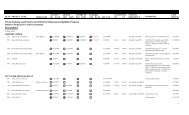
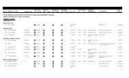
LIST OF FIGURES<br />
Figure No.<br />
After Page No.<br />
5-1 <strong>Pipe</strong> <strong>Material</strong> Selection Chart Reinforced Concrete <strong>Pipe</strong> ............................................................. 5-5<br />
5-2 <strong>Pipe</strong> <strong>Material</strong> Selection Chart Aluminized Steel <strong>Pipe</strong> .................................................................. 5-5<br />
5-3 <strong>Pipe</strong> <strong>Material</strong> Selection Chart Polymer Coated Steel <strong>Pipe</strong> ........................................................... 5-5<br />
5-4 <strong>Pipe</strong> <strong>Material</strong> Selection Chart Corrugated Aluminum <strong>Pipe</strong> .......................................................... 5-5<br />
5-5 <strong>Pipe</strong> <strong>Material</strong> Selection Chart Polyvinyl Chloride (PVC) pipe .................................................... 5-5<br />
5-6 <strong>Pipe</strong> <strong>Material</strong> Selection Chart High Density Polyethylene (HDPE) <strong>Pipe</strong> ..................................... 5-5<br />
6-1 Trench Detail – Reinforced Concrete <strong>Pipe</strong> ................................................................................... 6-4<br />
7-1 AISI Chart for Estimating Average Invert Life for Galvanized CSP ........................................... 7-3<br />
7-2 Trench Detail – Aluminized Steel <strong>Pipe</strong>......................................................................................... 7-5<br />
8-1 Trench Detail – Polymer Coated Steel <strong>Pipe</strong> ................................................................................. 8-4<br />
9-1 Trench Detail – Corrugated Aluminum <strong>Pipe</strong> .............................................................................. 9-5<br />
10-1 Trench Detail - Polyvinyl Chloride <strong>Pipe</strong>..................................................................................... 10-3<br />
11-1 Trench Detail – High Density Polyethylene <strong>Pipe</strong> ...................................................................... 11-3<br />
TOC-6
<strong>Storm</strong> <strong>Sewer</strong> <strong>Pipe</strong> <strong>Material</strong> <strong>Technical</strong> <strong>Memorandum</strong> 3 rd Edition<br />
July 13, <strong>2010</strong><br />
Executive Summary<br />
1.0 EXECUTIVE SUMMARY<br />
1.1 PURPOSE<br />
This <strong>Technical</strong> <strong>Memorandum</strong> provides guidance to local jurisdictions, Developers, Contractors,<br />
Inspectors, and Consultants in selecting, designing and installing pipe used for storm sewers. This<br />
memorandum provides the minimum guided criteria based on the National Standards of AASHTO and<br />
ASTM. Providing for facilities that go beyond the minimum recommendations provided is encouraged.<br />
In addition, there may other more specific or stringent local, state, and/or federal requirements that may<br />
also have to be met.<br />
This <strong>Technical</strong> <strong>Memorandum</strong> is a revision to the Update to <strong>Storm</strong> <strong>Sewer</strong> <strong>Pipe</strong> <strong>Material</strong> <strong>Technical</strong><br />
<strong>Memorandum</strong> prepared for the Urban Drainage and Flood Control District (District) and nine<br />
participating local governments in 1998 by Burns & McDonnell Engineering, Inc. The District along<br />
with thirteen local governments and agencies selected Burns & McDonnell Engineers to evaluate storm<br />
sewer pipe materials currently on the market in the Metro Denver area. An evaluation of current<br />
reference data was also performed for pipe materials reviewed in the 1998 update. The local governments<br />
and agencies participating in this update include:<br />
• Adams County • City of Golden<br />
• Arapahoe County • City of Lakewood<br />
• City of Arvada • Colorado Department of Transportation (CDOT)<br />
• City of Aurora • Town of Parker<br />
• City of Commerce City • City of Westminster<br />
• City and County of Denver • Southeast Metro <strong>Storm</strong> Water Authority (SEMSWA)<br />
• Douglas County • Urban Drainage and Flood Control District (<strong>UDFCD</strong>)<br />
The <strong>Technical</strong> <strong>Memorandum</strong> provides background information and in ground history for selected pipe<br />
materials, pipe material selection guides, specific design and service characteristics for each material,<br />
standard specifications and details, and an installation guide with inspection checklists.<br />
1.2 GENERAL DISCLAIMER<br />
This <strong>Technical</strong> <strong>Memorandum</strong> is intended to serve as a general guideline for the selection and installation<br />
of storm sewer pipe. It is the responsibility of the designer to evaluate each project individually to ensure<br />
that the specific project conditions are addressed, and local government standards are met.<br />
1.3 TECHNICAL MEMORANDUM HISTORY<br />
The <strong>Technical</strong> <strong>Memorandum</strong> has been updated several times in the last 23 years. The following is a<br />
listing of the history of the <strong>Storm</strong> <strong>Sewer</strong> <strong>Pipe</strong> <strong>Material</strong> <strong>Technical</strong> <strong>Memorandum</strong> from the most recent<br />
edition to the original:<br />
<strong>Storm</strong> <strong>Sewer</strong> <strong>Pipe</strong> <strong>Material</strong> <strong>Technical</strong> <strong>Memorandum</strong> – 3 rd Edition (<strong>2010</strong>)<br />
July <strong>2010</strong>, Burns & McDonnell Engineering, Inc.<br />
Update to <strong>Storm</strong> <strong>Sewer</strong> <strong>Pipe</strong> <strong>Material</strong> <strong>Technical</strong> <strong>Memorandum</strong><br />
March 1998, Burns & McDonnell Engineering, Inc.<br />
<strong>Storm</strong> <strong>Sewer</strong> <strong>Pipe</strong> <strong>Material</strong> <strong>Technical</strong> <strong>Memorandum</strong><br />
1-1
<strong>Storm</strong> <strong>Sewer</strong> <strong>Pipe</strong> <strong>Material</strong> <strong>Technical</strong> <strong>Memorandum</strong> 3 rd Edition<br />
July 13, <strong>2010</strong><br />
Executive Summary<br />
1987, Wright Water Engineers, Inc.<br />
1.4 PIPE MATERIALS EVALUATION<br />
The pipe materials evaluated for use in storm sewer applications were limited to materials that are<br />
typically used in the Denver Metropolitan area and are cost-competitive for storm sewer applications.<br />
The pipe materials evaluated include Reinforced Concrete <strong>Pipe</strong> (RCP), Aluminized Steel <strong>Pipe</strong> (ASP),<br />
Polymer Coated Steel <strong>Pipe</strong> (PCSP), Corrugated Aluminum <strong>Pipe</strong> (CAP), Polyvinyl Chloride <strong>Pipe</strong> (PVC),<br />
and High Density Polyethylene <strong>Pipe</strong> (HDPE). Most local governments specify 18-inches as the minimum<br />
diameter for a storm sewer; therefore the pipe materials evaluated were limited to 18-inches and larger.<br />
1.5 DATA COLLECTION<br />
A <strong>Storm</strong> <strong>Sewer</strong> <strong>Pipe</strong> <strong>Material</strong>s Inspection and Maintenance Practices Survey and a <strong>Storm</strong> <strong>Sewer</strong> <strong>Pipe</strong><br />
Rehabilitation (In-Place/No Dig) Practices Survey were developed and distributed to solicit input from<br />
each of the forty one member entities of the Urban Drainage & Flood Control District.<br />
Field inspections were conducted to gather information on existing storm sewer installations of different<br />
materials.<br />
Videos of existing storm sewer installations were evaluated in order to understand the in field service of<br />
different storm sewer materials.<br />
Specific product information was obtained from the pipe manufacturers during a presentation for each<br />
pipe material.<br />
Specific product information was also obtained from <strong>Pipe</strong> Manufacturer’s and Contractor’s during a<br />
presentation on storm sewer rehabilitation materials.<br />
<strong>Technical</strong> memorandum comments and input along with design information and pipe material selection<br />
information were gathered at a Design Engineer Focus workshop which was attended by reputable storm<br />
sewer designers from the Denver area.<br />
<strong>Technical</strong> memorandum comments regarding the pipe inspection guide, inspection and maintenance, and<br />
rehabilitation were gathered at the Inspection Contractor Focus workshop which was attended by<br />
Inspectors and Contractors from the Denver area.<br />
1.6 PIPE MATERIAL SELECTION GUIDE<br />
Each pipe material performs differently during installation and while in service, therefore individual<br />
installation procedures and trench details are required. Included within this memorandum are Design and<br />
Performance Checklists, Submittal Requirements, and a <strong>Pipe</strong> <strong>Material</strong>s Selection Guide. The following is<br />
a summary of each:<br />
• Design and Performance Checklist<br />
The design and performance checklist is provided to facilitate the designer in making sure that<br />
consideration has been given to the critical issues associated with storm sewer design. A checklist is<br />
presented that provides a minimum listing of items to be considered in the structural design of a storm<br />
sewer system. Hydrology and hydraulic requirements are not included in the checklist.<br />
• Submittal Requirements<br />
1-2
<strong>Storm</strong> <strong>Sewer</strong> <strong>Pipe</strong> <strong>Material</strong> <strong>Technical</strong> <strong>Memorandum</strong> 3 rd Edition<br />
July 13, <strong>2010</strong><br />
Executive Summary<br />
A list of information that may be required to be submitted with the design of a storm sewer system to<br />
local governments is presented. General information includes:<br />
° Soils characteristics<br />
° Design depth of cover<br />
° Groundwater level<br />
° Bedding class and factor (minimum/maximum)<br />
° Embedment material specification<br />
° Design loads<br />
° Buoyancy calculations (when applicable)<br />
° Typical trench detail<br />
° Trench bottom stabilization detail when required<br />
° Information to be submitted for pipe material is stated in the specifications<br />
° Hydrology, hydraulic, and area drainage characteristics<br />
• <strong>Pipe</strong> <strong>Material</strong> Selection<br />
A pipe material selection process is presented that provides several items of comparison for the<br />
designer/reviewer to consider.<br />
1-3
<strong>Storm</strong> <strong>Sewer</strong> <strong>Pipe</strong> <strong>Material</strong> <strong>Technical</strong> <strong>Memorandum</strong> 3 rd Edition<br />
July 13, <strong>2010</strong><br />
Executive Summary<br />
Item<br />
Minimum –<br />
Maximum<br />
<strong>Pipe</strong> Size<br />
(Inches)<br />
AASHTO<br />
Standard<br />
ASTM<br />
Standard<br />
Manning’s<br />
“n” Value<br />
Joints<br />
Typical<br />
Manufactured<br />
Length (feet)<br />
Minimum<br />
Stiffness (psi)<br />
Minimum<br />
Bury Depth<br />
(Feet)<br />
Maximum<br />
Bury Depth<br />
(feet)<br />
Chemical<br />
Resistance<br />
Abrasion<br />
Resistance<br />
Corrosion<br />
Resistance<br />
Connection<br />
Table 1-1<br />
Comparative Evaluation Summary of <strong>Pipe</strong>line <strong>Material</strong>s<br />
Aluminized Polymer Corrugated<br />
Steel <strong>Pipe</strong> Coated Aluminum<br />
(ASP) Steel <strong>Pipe</strong> <strong>Pipe</strong><br />
Reinforced<br />
Concrete <strong>Pipe</strong><br />
(RCP)<br />
Polyvinyl<br />
Chloride<br />
<strong>Pipe</strong> (PVC)<br />
High Density<br />
Polyethylene<br />
<strong>Pipe</strong> (HDPE)<br />
18-144 18-144 18-102 18-84 18-54* 18-60*<br />
M170 M242<br />
M36 M274<br />
M36 M245<br />
M246<br />
M196 M197<br />
C76 C655 A760 A929 A760 A762 B744 B745<br />
M304<br />
M278<br />
F697 F794<br />
F949<br />
M252 M294<br />
F894 F2306<br />
0.013 0.013 0.013 0.013 0.011 0.012<br />
Watertight<br />
Rubber Gasket<br />
Watertight<br />
Band Strip<br />
with O-ring<br />
Gasket<br />
Watertight<br />
Band Strip<br />
with O-ring<br />
or Gasket<br />
Watertight<br />
Band Strip<br />
with O-ring<br />
or Gasket<br />
Watertight<br />
Rubber<br />
Gasket<br />
Watertight<br />
Rubber Gasket<br />
7.5-8 20-40 20-40 20-40 13 & 22 20<br />
Rigid (Class<br />
III min)<br />
Class III-I-1’<br />
Class IR-R–0’<br />
See Table<br />
6-2<br />
See Table<br />
7-1 and<br />
Table 7-2<br />
Varies(1-2)<br />
See Table<br />
7-1<br />
See Table<br />
7-2<br />
See Table<br />
8-1 and<br />
Table 8-2<br />
Varies(1-2)<br />
See Table<br />
8-1<br />
See Table<br />
8-2<br />
See Table<br />
9-1 and 9-2<br />
Varies(1-1.2)<br />
See Table<br />
9-1<br />
See Table<br />
9-2<br />
Varies with<br />
diameter<br />
2.0 or 1<br />
pipe Dia.<br />
(ASTM<br />
D2321)<br />
See Table<br />
10-1<br />
Varies with<br />
diameter<br />
2.0 or 1 pipe<br />
Dia<br />
(ASTM<br />
D2321)<br />
See Table<br />
11-2<br />
Moderate Low High High High High<br />
Moderate<br />
See Section<br />
7-5<br />
High Moderate High High<br />
Moderate Low High Moderate High High<br />
Grouted or<br />
Insert Tee<br />
Saddle or<br />
Branch<br />
Saddle or<br />
Branch<br />
Saddle or<br />
Branch<br />
Insert Tee<br />
Insert Tee<br />
* Maximum diameter that is indicated in both the most recent AASHTO and ASTM standard. If the<br />
diameter is increased through a revision to the existing AASHTO or ASTM standard then the future<br />
user may consider using a larger pipe diameter size.<br />
<strong>Pipe</strong> material selection charts to aid in the selection of pipe materials for use in a storm drainage system<br />
are also presented in this memorandum. These charts present several conditions for each material which<br />
can easily be followed in a logical step-by-step flow chart manner to determine the applicability of each<br />
pipeline material for a particular installation. In general, Reinforced Concrete <strong>Pipe</strong> (RCP) is generally<br />
1-4
<strong>Storm</strong> <strong>Sewer</strong> <strong>Pipe</strong> <strong>Material</strong> <strong>Technical</strong> <strong>Memorandum</strong> 3 rd Edition<br />
July 13, <strong>2010</strong><br />
Executive Summary<br />
limited by wall thickness requirements, pH, sulfate levels, and minimum bury depth. Aluminized Steel<br />
<strong>Pipe</strong> (ASP), Polymer Coated Steel <strong>Pipe</strong> (PCSP) and Corrugated Aluminum <strong>Pipe</strong> (CAP) are generally<br />
limited by pH, soil resistivity, flotation, corrosive agents, abrasive flows, and minimum cover. Polyvinyl<br />
Chloride <strong>Pipe</strong> (PVC) is generally limited by size, ultraviolet degradation, flotation, pipe stiffness, and<br />
minimum cover depth. High Density Polyethylene (HDPE) <strong>Pipe</strong> is limited by UV degradation (although<br />
the addition of 2% carbon black is improving this for the exposed material), flotation, and maximum and<br />
minimum trench depth conditions. See specific sections in this memorandum on each pipe material and<br />
refer to the referenced standards for each material if the conditions or design criteria vary from those<br />
presented herein.<br />
1.7 STANDARD SPECIFICATION AND TRENCH DETAILS<br />
Standard specifications and trench details were developed to maintain consistency among the local<br />
government entities. In addition, it is anticipated that overall design and construction efficiency of future<br />
projects will be increased as a result of the standardized specifications. Standard specifications for each<br />
pipe material and a pipe installation specification is included in Appendix D of this memorandum and<br />
standard trench details for each pipe material are included in Chapters 5 through 11 of this memorandum.<br />
1.8 INSTALLATION GUIDE<br />
An installation guide is presented that provides a general overview of installation parameters. Included<br />
are specific installation checklists to serve as a guide for designers and inspectors to monitor in the field<br />
as construction progresses. Specific sections include summaries on the following topics:<br />
• Handling<br />
• Storage<br />
• Excavation<br />
• Bedding and Embedment<br />
• Placement<br />
• Backfill and Compaction<br />
• Inspection and Testing<br />
• Connections to Existing <strong>Storm</strong> <strong>Sewer</strong> Systems<br />
Installation checklists are provided for the following:<br />
• <strong>Pipe</strong> Inspection Checklist<br />
• Trench Excavation Checklist<br />
• <strong>Pipe</strong> Installation Checklist<br />
• Trench Backfill Checklist<br />
These installation parameters and checklists are not all encompassing, so specific project conditions must<br />
be evaluated individually; however, these general guidelines provide consistency in inspection<br />
requirements and also provide checklists that new inspectors can use as a baseline for inspections.<br />
* * * * *<br />
1-5
<strong>Storm</strong> <strong>Sewer</strong> <strong>Pipe</strong> <strong>Material</strong> <strong>Technical</strong> <strong>Memorandum</strong> 3 rd Edition<br />
July 13, <strong>2010</strong><br />
Introduction<br />
2.0 INTRODUCTION<br />
2.1 PURPOSE<br />
This <strong>Technical</strong> <strong>Memorandum</strong> is a revision to the Update to <strong>Storm</strong> <strong>Sewer</strong> <strong>Pipe</strong> <strong>Material</strong> <strong>Technical</strong><br />
<strong>Memorandum</strong> prepared for the Urban Drainage and Flood Control District (District) and nine<br />
participating local governments in 1998 by Burns & McDonnell Engineering, Inc. The District along<br />
with thirteen local governments and agencies selected Burns & McDonnell Engineers to evaluate storm<br />
sewer pipe materials currently on the market in the Metro Denver area. An evaluation of current<br />
reference data was also performed for pipe materials reviewed in the 1998 update. The local governments<br />
and agencies participating in this update include:<br />
• Adams County • City of Golden<br />
• Arapahoe County • City of Lakewood<br />
• City of Arvada • Colorado Department of Transportation (CDOT)<br />
• City of Aurora • Town of Parker<br />
• City of Commerce City • City of Westminster<br />
• City and County of Denver • Southeast Metro <strong>Storm</strong> Water Authority (SEMSWA)<br />
• Douglas County • Urban Drainage and Flood Control District (<strong>UDFCD</strong>)<br />
This <strong>Technical</strong> <strong>Memorandum</strong> provides a systematic approach for designers, inspectors, review agencies,<br />
and other local government staff. The <strong>Technical</strong> <strong>Memorandum</strong> provides background information and in<br />
ground history for selected pipe materials, pipe material selection guides, specific design and service<br />
characteristics for each material, standard specifications and details, and an installation guide with<br />
inspection checklists.<br />
This <strong>Technical</strong> <strong>Memorandum</strong> update is for storm sewers only and does not include culverts. <strong>Storm</strong><br />
sewers are defined as pipes used to convey storm water runoff along, or parallel to, streets or highways.<br />
Culverts are defined as pipes used to convey water under or generally perpendicular to highways,<br />
railroads, streets, embankments, or canals. <strong>Storm</strong> sewers typically have intermediate manholes, where<br />
culverts do not.<br />
2.2 SCOPE<br />
The pipe materials evaluated in this update were limited to the following:<br />
• Reinforced Concrete <strong>Pipe</strong> (RCP)<br />
• Aluminized Steel <strong>Pipe</strong> (ASP)<br />
• Polymer Coated Steel <strong>Pipe</strong> (PCSP)<br />
• Corrugated Aluminum <strong>Pipe</strong> (CAP)<br />
• Polyvinyl Chloride <strong>Pipe</strong> (PVC)<br />
• High Density Polyethylene <strong>Pipe</strong> (HDPE)<br />
The pipe sizes evaluated were limited to 18-inches in diameter and larger. Smaller pipes were not<br />
included as part of this pipe materials update.<br />
2-1
<strong>Storm</strong> <strong>Sewer</strong> <strong>Pipe</strong> <strong>Material</strong> <strong>Technical</strong> <strong>Memorandum</strong> 3 rd Edition<br />
July 13, <strong>2010</strong><br />
Introduction<br />
Specific tasks performed included the following:<br />
• Preparation and evaluation of a <strong>Storm</strong> <strong>Sewer</strong> <strong>Pipe</strong> <strong>Material</strong>s Inspection and Maintenance Practices<br />
Survey and a <strong>Storm</strong> <strong>Sewer</strong> <strong>Pipe</strong> Rehabilitation (In-Place/No Dig) Practices Survey to obtain input and<br />
feedback from each of the forty one member entities of the Urban Drainage & Flood Control District..<br />
• Field inspection of local storm sewer projects using the pipe materials to be evaluated.<br />
• Review of videos of existing storm sewer installations of different materials<br />
• Presentations by pipe Manufacturers and Contractor’s regarding pipe material, rehabilitation material<br />
and rehabilitation installation.<br />
• Design Engineer Focus Workshop was held to obtain insight into the materials currently used and<br />
design practices regarding the <strong>Storm</strong> <strong>Sewer</strong> <strong>Pipe</strong> <strong>Material</strong> <strong>Technical</strong> <strong>Memorandum</strong>.<br />
• An Inspector and Contractor Workshop was held to gather comments regarding pipe inspection guide,<br />
inspection and maintenance, and rehabilitation of storm sewers.<br />
In addition, the scope of this update included the following technical analyses:<br />
• Preparation of a <strong>Pipe</strong> <strong>Material</strong>s Selection Guide that defines the limits for each pipe material. Limits<br />
include minimum and maximum fill heights, soil and water parameters, abrasion, and other factors<br />
that affect the performance of the pipe.<br />
• Preparation of detailed specifications for each pipe material.<br />
• Revision and preparation of detailed installation specifications and an installation guide to assist<br />
engineers and inspectors.<br />
• Revision and preparation of standard trench details to be used for each pipe installation.<br />
This pipe materials update presents the consensus of the project sponsors regarding each pipe material<br />
and recommended installation methods and materials for the Metropolitan Denver area and the local<br />
governments within the District’s boundaries. References for detailed design criteria, standards,<br />
guidelines, and manufacturers’ recommendations should also be used if a particular application does not<br />
fit the criteria and guidelines recommended herein. In addition, the engineer should contact the District,<br />
or the particular local government, regarding deviations and extenuating circumstances.<br />
* * * * *<br />
2-2
<strong>Storm</strong> <strong>Sewer</strong> <strong>Pipe</strong> <strong>Material</strong> <strong>Technical</strong> <strong>Memorandum</strong> 3 rd Edition<br />
July 13, <strong>2010</strong><br />
Data Collection<br />
3.0 DATA COLLECTION<br />
3.1 PREVIOUS EVALUATION<br />
In early 1987, the District, in coordination with Arapahoe County and the City of Littleton, selected<br />
Wright Water Engineers, Inc. of Denver, Colorado to develop design and technical criteria for various<br />
storm sewer pipe materials. The Study, titled “<strong>Storm</strong> <strong>Sewer</strong> <strong>Pipe</strong> <strong>Material</strong> <strong>Technical</strong> <strong>Memorandum</strong>” was<br />
developed to allow the project sponsors to permit orderly, cost-effective, selection of storm sewer pipe<br />
materials.<br />
The Study was limited to the following pipe materials:<br />
• Reinforced Concrete <strong>Pipe</strong> with various cement types<br />
• Corrugated steel pipe, bituminous coated corrugated steel pipe, and fiber bonded coated corrugated<br />
steel pipe<br />
• Corrugated aluminum pipe and coated corrugated aluminum pipe<br />
• Various types of plastic pipe<br />
The Study was limited to storm sewer applications and specifically excluded culverts. A storm sewer was<br />
defined as a pipe used to convey storm water runoff along streets or highways. A culvert was defined as a<br />
closed conduit for passing water under a highway, railroad, canal, or embankment.<br />
The 1987 Study included a literature search and life cycle cost analysis, identified material selection<br />
factors, provided a material overview, and provided information on coatings, structural design,<br />
installation, durability, and rehabilitation for each material identified. In addition, a survey of storm<br />
sewer pipe material practices was sent to a number of Colorado Front Range cities and counties, and to<br />
major cities and counties in the Midwest to Western United States. The survey requested information on<br />
material types, soil/environment conditions, construction quality control, maintenance, and rehabilitation<br />
methods.<br />
In March of 1988, a supplement to the original Study was completed that provided additional discussion<br />
on construction materials, including brief discussions on pipe embedment, backfill/compaction, and<br />
inspection/testing. The supplement also provided discussion on the structural design of each of the pipe<br />
materials evaluated.<br />
3.2 PUBLISHED MATERIAL<br />
A comprehensive approach was developed to compile data and information for the memorandum.<br />
Published material was provided by various pipe trade associations, manufacturers, and suppliers of pipe<br />
materials for information on their products. A literature search was also conducted in 1988 that included<br />
articles, reports, memorandums, and other material from a variety of sources, including the U. S. Army<br />
Corps of Engineers, state departments of transportation, universities, American Society of Civil<br />
Engineers, Federal Highway Administration, American Association of State Highway and Transportation<br />
Officials, American Society for Testing and <strong>Material</strong>s, and private consultants. A comprehensive<br />
bibliography of the research literature is provided in the Section 15 of this <strong>Memorandum</strong>.<br />
3-1
<strong>Storm</strong> <strong>Sewer</strong> <strong>Pipe</strong> <strong>Material</strong> <strong>Technical</strong> <strong>Memorandum</strong> 3 rd Edition<br />
July 13, <strong>2010</strong><br />
Data Collection<br />
3.3 STORM SEWER PIPE MATERIALS INSPECTION AND MAINTENANCE<br />
SURVEY<br />
A <strong>Storm</strong> <strong>Sewer</strong> <strong>Pipe</strong> <strong>Material</strong>s Inspection and Maintenance Survey was developed to solicit input from<br />
each of the forty one member entities of the Urban Drainage & Flood Control District in July 2009. The<br />
<strong>Storm</strong> <strong>Sewer</strong> <strong>Pipe</strong> <strong>Material</strong> Inspection and Maintenance Survey requested information on storm sewer<br />
maintenance and storm sewer inspection post construction. A total of 24 of 41 surveys were returned. A<br />
summary of responses to the survey are presented in Appendix A.<br />
In summary, 10 of the 25 respondents have their storm sewer system on a regular inspection program.<br />
The rest of the respondents either maintain their system based on historical performance or as problems<br />
occur. Typically, the storm sewer system is inspected via CCTV or by visual inspection. The most<br />
commonly occurring pipe defects were sedimentation and joint separation. High pressure water jetting<br />
and vacuum removal of sediment are the most frequent activities regarding storm sewer maintenance.<br />
3.4 STORM SEWER PIPE REHABILITATION (IN-PLACE/NO DIG) PRACTICES<br />
SURVEY<br />
A <strong>Storm</strong> <strong>Sewer</strong> <strong>Pipe</strong> Rehabilitation (In-Place/No Dig) Practices Survey was developed to solicit input<br />
from each of the forty one member entities of Urban Drainage & Flood Control District in July 2009. The<br />
<strong>Storm</strong> <strong>Sewer</strong> <strong>Pipe</strong> Rehabilitation (In-Place/No Dig) Practices Survey requested information on storm<br />
sewer rehabilitation. A total of 16 of 41 surveys were returned and two entities indicated that they did not<br />
currently perform rehabilitation on storm sewers. A summary of the responses to the survey are presented<br />
in Appendix B.<br />
In summary, 5 of the 16 respondents have used sliplining methods for storm sewer rehabilitation. The<br />
materials used were PVC and ASP. No respondents indicated that Cured in Place <strong>Pipe</strong> is currently being<br />
utilized for storm sewer rehabilitation.<br />
3.5 FIELD SITE VISITS<br />
Field site visits were conducted in the initial stages of the Study to evaluate existing storm sewer<br />
installations. During a progress meeting it was decided that field site visits would take place for ASP,<br />
HDPE and RCP pipe. The locations where the site visits took place were some of the same locations that<br />
were visited during the 1998 review. This was deliberate so that investigation would determine if any<br />
noticeable changes had occurred in the 10 year period of time since last inspection. Field Site Visits were<br />
conducted on August 5, 2009 and August 17, 2009. Attendees were permitted to pass through the storm<br />
sewer and inspect the condition of the pipeline. During and after each inspection, participants discussed<br />
their observations and provided comments on the apparent performance of the storm sewer pipe material,<br />
condition of the pipeline, noted problems or deficiencies in the pipeline, installation, and other general<br />
observations. Photographs were taken at each of the field inspection sites of pipeline interiors and items<br />
of significance that were noted. Following is a short summary of the field inspections, including sites,<br />
locations, material data, and size of the storm sewer. A comprehensive memorandum of field trip<br />
observations is included in Appendix C.<br />
3-2
<strong>Storm</strong> <strong>Sewer</strong> <strong>Pipe</strong> <strong>Material</strong> <strong>Technical</strong> <strong>Memorandum</strong> 3 rd Edition<br />
July 13, <strong>2010</strong><br />
Data Collection<br />
Table 3-1<br />
Field Site Visits<br />
<strong>Storm</strong> <strong>Sewer</strong> Name Location <strong>Material</strong><br />
West Woods Golf<br />
Course<br />
Slaughter House<br />
Gulch Phase IV<br />
Washington Street<br />
Improvements<br />
Soundtrack (Ultimate<br />
Electronics)<br />
August 5, 2009<br />
Quaker Street at the entrance<br />
to the Golf course<br />
S. Grant Street and E.<br />
Maplewood Drive, E.<br />
Maplewood Drive and S.<br />
Pennsylvania Street<br />
E 120 th Avenue and<br />
Washington Street<br />
3.6 CCTV REVIEW OF STORM SEWERS<br />
August 17, 2009<br />
Size<br />
(Inches)<br />
Date of<br />
Installation<br />
Aluminized CMP 72 and 80 ~1994<br />
RCP<br />
48 to 76<br />
elliptical<br />
1994<br />
HDPE 48 1995<br />
84 th Avenue and I-25 HDPE 48 1995<br />
CCTV reviews were preformed on a number of the storm sewer sites that were visited and walked<br />
through during the 1998 update. The following is a short summary of the CCTV review of the storm<br />
sewer including sites, locations, material data, and size of the storm sewer. A comprehensive summary of<br />
the CCTV review is included in Appendix D.<br />
Table 3-2<br />
CCTV Review of <strong>Storm</strong> <strong>Sewer</strong>s<br />
<strong>Storm</strong> <strong>Sewer</strong> Name Location <strong>Material</strong><br />
Knoxville <strong>Storm</strong> <strong>Sewer</strong><br />
Summer Valley Ranch<br />
– 4B<br />
Summer Valley Ranch<br />
– 4A<br />
Women Creek<br />
Reservoir Drain<br />
Knox Court <strong>Storm</strong><br />
<strong>Sewer</strong><br />
Saddle Rock Golf<br />
Course<br />
Virginia Village Phase<br />
II<br />
S. Lamar Street between Dartmouth<br />
Avenue and Yale Avenue<br />
In easement between houses south of<br />
S. Reservoir Road between Biscay<br />
Road and S. Catha Way<br />
S. Reservoir Road between Biscay<br />
Road and S. Cathay Way<br />
West of 112 th Avenue and Simms<br />
Street<br />
Size<br />
(Inches)<br />
Date of<br />
Installation<br />
RCP 15- 42 1994<br />
RCP 42 1991<br />
HDPE 36 1993<br />
HDPE 24 1995<br />
Knox Court and Hampden Avenue ASP 36 1995<br />
North of Arapahoe Road and 1800<br />
feet east of S. Liverpool Street (near<br />
clubhouse)<br />
East Minnesota Drive and South<br />
Jasmine Street<br />
ASP 18-48 1996<br />
CMP 24-42 2000<br />
3-3
<strong>Storm</strong> <strong>Sewer</strong> <strong>Pipe</strong> <strong>Material</strong> <strong>Technical</strong> <strong>Memorandum</strong> 3 rd Edition<br />
July 13, <strong>2010</strong><br />
Data Collection<br />
3.7 PIPE MANUFACTURER STORM SEWER MATERIAL PRESENTATION<br />
On July 10, 2009 a manufacturer’s presentation on existing and new storm sewer products was held at the<br />
offices of <strong>UDFCD</strong>. <strong>Pipe</strong> manufacturers were encouraged to be present for their competitor’s<br />
presentations. Presentations were scheduled for each of the local pipe manufacturers showing interest in<br />
the project for the pipe materials to be included in the evaluation. The presentations were attended by<br />
<strong>UDFCD</strong>, project sponsors, Burns & McDonnell, and the pipe manufacturers. Presentations provided<br />
product information and allowed participants the opportunity for questions and answers. Information<br />
presented included the following:<br />
• Existing <strong>Storm</strong> <strong>Sewer</strong> Products<br />
• Newer <strong>Storm</strong> <strong>Sewer</strong> Products<br />
• Joints<br />
• End Section<br />
• Installation Issues and Solutions<br />
• Preferred Bedding <strong>Material</strong><br />
• Items the manufacturers would like to see included in the updated <strong>Technical</strong> <strong>Memorandum</strong><br />
Presentations were made by the following:<br />
• Mountain States Concrete <strong>Pipe</strong> Association and Rinker <strong>Material</strong>s (RCP)<br />
• KWH <strong>Pipe</strong> (HDPE)<br />
• Advanced Drainage Solutions/Hancor (HDPE)<br />
• Contech (ASP)<br />
3.8 PIPE MANUFACTURERS REHABILITATION PRESENTATIONS<br />
On August 19, 2009 a manufacturer’s presentation on rehabilitation products was held at the offices of<br />
<strong>UDFCD</strong>. Presentations were scheduled for each of the local pipe manufacturers showing an interest in<br />
the project. The presentations were attended by <strong>UDFCD</strong>, project sponsors, Burns & McDonnell, pipe<br />
manufacturer of rehabilitation products, and a contractor who has installed many rehabilitation products<br />
for storm sewers. Presentations provided product information and allowed participants the opportunity<br />
for questions and answers. Information presented included the following:<br />
• <strong>Storm</strong> <strong>Sewer</strong> Rehabilitation Products<br />
• Joints<br />
• Termination at End Sections<br />
• Filling of Voids Between Host <strong>Pipe</strong> and Rehabilitation Product<br />
Presentations were made by the following:<br />
• KWH <strong>Pipe</strong> (Sliplining)<br />
• Advanced Drainage Solutions/Hancor (Sliplining)<br />
• Contech (Sliplining)<br />
• Wildcat (Cured in Place <strong>Pipe</strong>)<br />
• C&L Water Solutions (Cured in Place <strong>Pipe</strong>)<br />
• American West Contractors (<strong>Storm</strong> <strong>Sewer</strong> Rehabilitation Product Installers)<br />
3.9 DESIGN ENGINEER FOCUS GROUP<br />
On August 12, 2009 a meeting with local storm sewer designers that have worked with <strong>UDFCD</strong> on past<br />
projects was held to discuss the technical manual and proposed updates to the manual. Attendees<br />
included representatives from the following entities: Urban Drainage & Flood Control District; Burns &<br />
McDonnell; and storm sewer designers. Discussion included storm sewer piping material, factors<br />
3-4
<strong>Storm</strong> <strong>Sewer</strong> <strong>Pipe</strong> <strong>Material</strong> <strong>Technical</strong> <strong>Memorandum</strong> 3 rd Edition<br />
July 13, <strong>2010</strong><br />
Data Collection<br />
considered in choosing storm sewer material, evaluation of Design Documents currently in the <strong>Technical</strong><br />
Manual, inspection and maintenance considerations, and storm sewer rehabilitation. General discussion<br />
and comments are presented in Appendix E.<br />
3.10 INSPECTOR AND CONTRACTOR FOCUS GROUP<br />
On September 9, 2009 a meeting with local Inspectors and Contractors that have worked with storm<br />
sewers to discuss storm sewer pipe materials. Attendees included representatives from the following<br />
entities: Urban Drainage & Flood Control District; City and County of Denver, Town of Parker, City of<br />
Westminster, City of Arvada, City of Aurora, Arapahoe Utility and Infrastructure Construction, and<br />
Burns & McDonnell. Discussion included the technical manual and use of the technical manual for<br />
inspection and construction, pipe installation guide, inspection, maintenance and storm sewer<br />
rehabilitation. General discussion and comments are presented in Appendix F.<br />
* * * * *<br />
3-5
<strong>Storm</strong> <strong>Sewer</strong> <strong>Pipe</strong> <strong>Material</strong> <strong>Technical</strong> <strong>Memorandum</strong> 3 rd Edition<br />
July 13, <strong>2010</strong><br />
<strong>Pipe</strong> <strong>Material</strong> Evaluation<br />
4.0 PIPE MATERIAL EVALUATION<br />
4.1 GENERAL<br />
<strong>Pipe</strong> materials evaluated for use in storm sewer applications were limited to materials that are typically<br />
used in the Denver area and are cost-competitive for storm sewer applications. The pipe materials<br />
evaluated include Reinforced Concrete <strong>Pipe</strong> (RCP), Aluminized Steel <strong>Pipe</strong> (Spiral Ribbed Aluminized<br />
Steel <strong>Pipe</strong> [ASP]), Polymer Coated Steel <strong>Pipe</strong> (PCSP), Corrugated Aluminum <strong>Pipe</strong> (CAP), Polyvinyl<br />
Chloride <strong>Pipe</strong> (PVC), and High Density Polyethylene <strong>Pipe</strong> (HDPE).<br />
4.2 REINFORCED CONCRETE PIPE (RCP)<br />
Reinforced Concrete <strong>Pipe</strong> has provided service as a storm sewer piping material for many years. RCP is<br />
produced locally by Rinker <strong>Material</strong>s, Precast Concepts, and Oldcastle Precast. RCP has an excellent<br />
performance history in excess of 75 years of service for this application. Reinforced Concrete <strong>Pipe</strong> offers<br />
pipe sizes up to 144-inches in diameter. The wall thickness and reinforcement requirements are<br />
determined by the pipe diameter and required bury depth in the structural design of the pipe. Rubber<br />
gaskets provide a water tight joint. AASHTO M170 and M242 and ASTM C76, C361, C443, and C655<br />
are the standards for this pipe.<br />
4.3 ALUMINIZED STEEL PIPE (ASP)<br />
Spiral ribbed Aluminized Steel <strong>Pipe</strong> (ASP) was introduced in 1984 as an alternative to conventional<br />
Corrugated Metal <strong>Pipe</strong> for storm sewer applications. Test reports indicate that the aluminized Type 2<br />
coating offers higher resistance to corrosion than galvanized steel. <strong>Pipe</strong> is available up to 144-inches in<br />
diameter and 40-foot laying lengths. Hugger type coupling bands with rubber O-ring gaskets are used to<br />
join the pipe. ASP is produced locally by Contech Construction Products, Inc. AASHTO M274 and<br />
ASTM A929 are the standards for this pipe.<br />
4.4 POLYMER COATED STEEL PIPE (PCSP)<br />
Polymer Coated Steel <strong>Pipe</strong> (PCSP) was introduced as an alternative to conventional Corrugated Metal<br />
<strong>Pipe</strong> for storm sewer applications. Polymer coated steel pipe can be used in areas that required additional<br />
protection against corrosion and abrasion. It can handle lower pH ranges and lower resistivity than ASP<br />
pipe. The polymer coating has the ability to handle heavy scour environments under high bed loading.<br />
The polymer coated steel pipe is available in both spiral rib pipe (Type 1R) and corrugated exterior<br />
profile with a smooth interior liner (Type 1A). AASHTO M36 and M246 and ASTM A762 are the<br />
standards for this pipe. The pipe is acceptable in the standards from 18-inch to 102-inch.<br />
4.5 CORRUGATED ALUMINUM PIPE (CAP)<br />
Corrugated Aluminum <strong>Pipe</strong> (CAP) was introduced as an alternative to conventional Corrugated Metal<br />
<strong>Pipe</strong> for storm sewer applications. Spiral ribbed aluminum pipe can be used in areas that require<br />
additional protection against corrosion and abrasion. It can handle lower pH ranges and has even<br />
been tested in salt water environments. AASHTO M196 and ASTM A745 are the standards for<br />
this pipe. The pipe is acceptable in the standards from 18-inch to 84-inch.<br />
4.6 POLYVINYL CHLORIDE PIPE (PVC)<br />
Polyvinyl Chloride <strong>Pipe</strong> is available in solid wall and profile wall designs that include open profile (i.e.<br />
ribbed exterior with smooth interior) and closed profile (smooth exterior and interior). PVC is available<br />
4-1
<strong>Storm</strong> <strong>Sewer</strong> <strong>Pipe</strong> <strong>Material</strong> <strong>Technical</strong> <strong>Memorandum</strong> 3 rd Edition<br />
July 13, <strong>2010</strong><br />
<strong>Pipe</strong> <strong>Material</strong> Evaluation<br />
in various diameters, but is limited to 54-inches in diameter for storm sewers. The material is lightweight<br />
and offers excellent corrosion and abrasion resistance. <strong>Pipe</strong> is available in 13 or 22-foot laying lengths<br />
with rubber gasketed bell and spigot joints. The material is susceptible to ultraviolet degradation. PVC is<br />
available locally from several suppliers. AASHTO M304 and ASTM F679, F794, F949, and F1803 are<br />
the standards for this pipe.<br />
4.7 HIGH DENSITY POLYETHYLENE PIPE (HDPE)<br />
High Density Polyethylene <strong>Pipe</strong> (HDPE) is produced in single wall corrugated interior pipe and dual wall<br />
corrugated pipe with a smooth interior. This product is limited to corrugated pipe with a smooth interior<br />
and is limited to a maximum size of 60-inches in diameter (based on current AASHTO M294), although<br />
larger diameters are manufactured. The material is lightweight and offers excellent corrosion and<br />
abrasion resistance. HDPE is available from Advanced Drainage System Inc. and KWH <strong>Pipe</strong>. AASHTO<br />
M252 and M294 and ASTM F894 and F2306 are the standards for this pipe.<br />
* * * * *<br />
4-2
<strong>Storm</strong> <strong>Sewer</strong> <strong>Pipe</strong> <strong>Material</strong> <strong>Technical</strong> <strong>Memorandum</strong> 3 rd Edition<br />
July 13, <strong>2010</strong><br />
<strong>Pipe</strong> <strong>Material</strong> Selection Guide<br />
5.0 PIPE MATERIAL SELECTION GUIDE<br />
5.1 TOTAL SYSTEM EVALUATION<br />
A total system evaluation requires that area drainage characteristics are defined and subsurface<br />
investigations be performed to collect samples and perform laboratory analysis to provide comprehensive<br />
design information for the storm drainage system. These investigations may be obtained from other<br />
subsurface investigations performed for roadway, sanitary sewer, or other utility designs, or a projectspecific<br />
geotechnical investigation may be required. Subsurface investigations for the purpose of the<br />
storm drainage system design should be performed at locations along the alignment that will provide the<br />
designer with representative conditions throughout the project area. In order to provide a comprehensive<br />
design, extreme existing conditions should be located, sampled, and reported to assure the integrity of the<br />
completed system. The following is a list of the basic elements required for the design:<br />
• Subsurface investigations<br />
° Soils sampling<br />
° Water table information<br />
° Groundwater fluctuations due to dry and wet weather conditions<br />
• Soils characteristics<br />
° Moisture content<br />
° Compactibility<br />
° Soil Classification<br />
° Stability<br />
° Industrial waste products (Hydrocarbons)<br />
° Organic contaminants<br />
° pH<br />
° Sulphate (total as SO 3 )<br />
° Subsidence<br />
° Soil resistivity<br />
• Area drainage characteristics<br />
• Anticipated trench condition<br />
• <strong>Pipe</strong> structural requirements<br />
° Loading conditions<br />
° Earth load<br />
° Live load (i.e., H20, E80, etc.)<br />
° Buoyancy<br />
• Bedding requirements<br />
• <strong>Pipe</strong> location with respect to other utilities<br />
5-1
<strong>Storm</strong> <strong>Sewer</strong> <strong>Pipe</strong> <strong>Material</strong> <strong>Technical</strong> <strong>Memorandum</strong> 3 rd Edition<br />
July 13, <strong>2010</strong><br />
<strong>Pipe</strong> <strong>Material</strong> Selection Guide<br />
5.2 DESIGN AND PERFORMANCE CHECKLIST<br />
The design and performance checklist is provided to facilitate the designer in consideration of critical<br />
issues associated with storm sewer design. The checklist presented in Table 5-I provides a minimum<br />
listing of items to be considered in the structural design of a storm sewer system. Hydrology and<br />
hydraulic requirements are not included in the checklist.<br />
Table 5-1<br />
Design and Performance Checklist<br />
Criteria Yes No<br />
Does the material provide service life established for the project?<br />
Is the size of the storm sewer based on the established storm frequency/intensity<br />
period?<br />
Is the velocity, based on the established storm frequency/intensity period, acceptable?<br />
Have the soils analysis and sampling been incorporated in the design?<br />
Does the structural design of the pipe meet the anticipated trench load conditions?<br />
Is the pipe manufactured in the required size range under present material specification<br />
standards?<br />
Will the pipe be subjected to organic or petroleum contaminants?<br />
Is the pipe material applicable for installation in contaminated areas?<br />
Is the installation subject to flotation?<br />
Are the pipe joints water tight?<br />
Are the structural characteristics compatible with the proposed design depth of the<br />
sewer minimum/maximum?<br />
Are the trench conditions compatible with the material to be installed?<br />
Is the pipe material compatible with the existing soil characteristics?<br />
Are changing trench conditions anticipated for the system life?<br />
Will installation of parallel utilities affect the pipeline integrity?<br />
Is bedding material acceptable if subsurface flow is present?<br />
5.3 SUBMITTAL REQUIREMENTS<br />
The following list of information may be required to be submitted with the design of a storm sewer<br />
system.<br />
• Soils characteristics<br />
° Moisture content<br />
° pH<br />
° Compactibility<br />
° Sulphate (total as SO 3 )<br />
° Soil Classification<br />
° Subsidence<br />
° Stability<br />
° Soil resistivity<br />
5-2
<strong>Storm</strong> <strong>Sewer</strong> <strong>Pipe</strong> <strong>Material</strong> <strong>Technical</strong> <strong>Memorandum</strong> 3 rd Edition<br />
July 13, <strong>2010</strong><br />
<strong>Pipe</strong> <strong>Material</strong> Selection Guide<br />
° Hydrocarbons/organic contaminants<br />
• Design depth of cover<br />
• Groundwater level<br />
• Bedding class and factor (minimum/maximum)<br />
• Embedment material specification<br />
• Design loads<br />
° Earth load<br />
° Live load (H20/E80)<br />
• Buoyancy calculations (when applicable)<br />
• Typical trench detail<br />
• Trench bottom stabilization detail when required<br />
• Information to be submitted for pipe material is stated in the specifications<br />
• Hydrology, hydraulic, and area drainage characteristics<br />
5.4 PIPE MATERIAL SELECTION<br />
The material selection process provides several items of comparison for the designer to consider.<br />
Following is a comparative evaluation summary of the pipeline materials:<br />
5-3
<strong>Storm</strong> <strong>Sewer</strong> <strong>Pipe</strong> <strong>Material</strong> <strong>Technical</strong> <strong>Memorandum</strong> 3 rd Edition<br />
July 13, <strong>2010</strong><br />
<strong>Pipe</strong> <strong>Material</strong> Selection Guide<br />
Item<br />
Minimum –<br />
Maximum<br />
<strong>Pipe</strong> Size<br />
(Inches)<br />
AASHTO<br />
Standard<br />
ASTM<br />
Standard<br />
Manning’s<br />
“n” Value<br />
Joints<br />
Typical<br />
Manufactured<br />
Length (feet)<br />
Minimum<br />
Stiffness (psi)<br />
Minimum<br />
Bury Depth<br />
(Feet)<br />
Maximum<br />
Bury Depth<br />
(feet)<br />
Chemical<br />
Resistance<br />
Abrasion<br />
Resistance<br />
Corrosion<br />
Resistance<br />
Table 5-2<br />
Comparative Evaluation Summary of <strong>Pipe</strong>line <strong>Material</strong>s<br />
Aluminized Polymer<br />
Aluminum<br />
Steel <strong>Pipe</strong> Coated<br />
<strong>Pipe</strong><br />
(ASP) Steel <strong>Pipe</strong><br />
Reinforced<br />
Concrete <strong>Pipe</strong><br />
(RCP)<br />
Polyvinyl<br />
Chloride<br />
<strong>Pipe</strong> (PVC)<br />
High Density<br />
Polyethylene<br />
<strong>Pipe</strong> (HDPE)<br />
18-144 18-144 18-102 18-84 18-54* 18-60*<br />
M170 M242<br />
M36 M274<br />
M36 M245<br />
M246<br />
M196 M197<br />
C76 C655 A760 A929 A760 A762 B744 B745<br />
M304<br />
M278<br />
F697 F794<br />
F949<br />
M252 M294<br />
F894 F2306<br />
0.013 0.013 0.013 0.013 0.011 0.012<br />
Watertight<br />
Rubber Gasket<br />
Watertight<br />
Band Strip<br />
with O-ring<br />
Gasket<br />
Watertight<br />
Band Strip<br />
with O-ring<br />
or Gasket<br />
Watertight<br />
Band Strip<br />
with O-ring<br />
or Gasket<br />
Watertight<br />
Rubber<br />
Gasket<br />
Watertight<br />
Rubber Gasket<br />
7.5-8 20-40 20-40 20-40 13 & 22 20<br />
Rigid (Class<br />
III min)<br />
Class III-I -1’<br />
Class IR-R–0’<br />
See Table<br />
6-2<br />
See Table<br />
7-1 and<br />
Table 7-2<br />
Varies(1-2)<br />
See Table<br />
7-1<br />
See Table<br />
7-2<br />
See Table<br />
8-1 and<br />
Table 8-2<br />
Varies(1-2)<br />
See Table<br />
8-1<br />
See Table<br />
8-2<br />
See Table<br />
9-1 and 9-2<br />
Varies(1-1.2)<br />
See Table<br />
9-1<br />
See Table<br />
9-2<br />
Varies with<br />
diameter<br />
2.0 or<br />
1 pipe Dia.<br />
(ASTM<br />
D2321)<br />
See Table<br />
10-1<br />
Varies with<br />
diameter<br />
2.0 or<br />
1 pipe Dia.<br />
(ASTM<br />
D2321)<br />
See Table<br />
11-2<br />
Moderate Low High High High High<br />
Moderate<br />
See Section<br />
7-5<br />
High Moderate High High<br />
Moderate Low High Moderate High High<br />
Grouted or Saddle or Saddle or Saddle or<br />
Connection<br />
Insert Tee Insert Tee<br />
Insert Tee Branch Branch Branch<br />
* Maximum diameter that is indicated in both the most recent AASHTO and ASTM standard. If the<br />
diameter is increased through a revision to the existing AASHTO or ASTM standard then the future<br />
user may consider using the larger pipe diameter size.<br />
5-4
<strong>Storm</strong> <strong>Sewer</strong> <strong>Pipe</strong> <strong>Material</strong> <strong>Technical</strong> <strong>Memorandum</strong> 3 rd Edition<br />
July 13, <strong>2010</strong><br />
<strong>Pipe</strong> <strong>Material</strong> Selection Guide<br />
<strong>Pipe</strong> material selection charts to aid in the selection of pipe materials for use in a storm drainage systems<br />
are presented in Figures 5-1, 5-2, 5-3, 5-4, 5-5 and 5-6. These charts present several conditions for each<br />
material which can easily be followed in a logical step-by-step flow chart manner to determine the<br />
applicability of each pipeline material for a particular installation. In general:<br />
• Reinforced Concrete <strong>Pipe</strong> (RCP) is generally limited by wall thickness requirements, pH, sulfate<br />
levels, and minimum bury depth.<br />
• Aluminized Steel <strong>Pipe</strong> (ASP), Polymer Coated Steel <strong>Pipe</strong> and Corrugated Aluminum <strong>Pipe</strong> are<br />
generally limited by pH, soil resistivity, flotation, corrosive agents, abrasive flows, and minimum<br />
cover.<br />
• Polyvinyl Chloride <strong>Pipe</strong> (PVC) is generally limited by size, ultraviolet (UV) degradation,<br />
flotation, pipe stiffness, and minimum cover depth.<br />
• High Density Polyethylene (HDPE) <strong>Pipe</strong> is limited by UV degradation, flotation, and maximum<br />
and minimum trench depth conditions.<br />
See specific sections in this memorandum on each pipe material and refer to the referenced standards for<br />
each material if the conditions or design criteria vary from those presented herein.<br />
* * * * *<br />
5-5
REINFORCED CONCRETE PIPE (RCP)<br />
YES<br />
Is pipe size greater than 144"<br />
diameter?<br />
NO<br />
YES<br />
Determine controlling fill Height<br />
Range in feet and determine class<br />
NO<br />
YES<br />
Is maximum pipe thickness<br />
required greater than pipe<br />
NO<br />
YES<br />
Is soil pH less than 5?<br />
NO<br />
Are soil sulfate levels > 0.20%?<br />
YES<br />
NO<br />
Use Type<br />
V cement<br />
YES<br />
Is minimum cover height less than<br />
1 foot or is this acceptable by<br />
NO<br />
Is flow velocity in the pipe greater<br />
than 20 ft/sec?<br />
YES<br />
NO<br />
Increasing concrete<br />
strength and<br />
Increasing specific<br />
hardness of the<br />
aggregate will be<br />
required<br />
Reinforced concrete pipe is not<br />
an acceptable alternative for<br />
this installation<br />
Reinforced concrete pipe is an<br />
acceptable alternative for this<br />
installation based on ASTM and<br />
AASHTO standards<br />
Selection of this alternate is complete.<br />
Proceed to the next pipe type selection.<br />
Figure 5-1<br />
<strong>Pipe</strong> <strong>Material</strong> Selection Chart<br />
Reinforced Concrete <strong>Pipe</strong>
ALUMINIZED STEEL PIPE (ASP)<br />
YES<br />
Is pipe size greater than 102" in<br />
diameter?<br />
NO<br />
Determine controlling fill height in feet<br />
and determine gauge of pipe<br />
NO<br />
Is maximum fill height permitted by<br />
maximum wall thickness pipe less than<br />
actual fill heights?<br />
YES<br />
YES<br />
Is soil moisture content greater than<br />
17.5%?<br />
NO<br />
NO<br />
Is soil pH range between 5 to 9?<br />
YES<br />
NO<br />
Is resistivity greater than or equal to<br />
1000 ohm-cm?<br />
NO<br />
Is resistivity greater than 1000<br />
ohm-cm and pH between 5.0 and<br />
9.0?<br />
YES<br />
YES<br />
Dewatering<br />
activities will be<br />
required during<br />
construction<br />
activities<br />
YES<br />
YES<br />
YES<br />
Is there a high groundwater table<br />
where floating may be a problem?<br />
NO<br />
Deicing chemicals (corrosive to<br />
Alumized steel), agricultural, or other<br />
corrosive agents may be flushed into<br />
the <strong>Storm</strong> <strong>Sewer</strong>?<br />
NO<br />
Is bed load heavy and velocity greater<br />
than 15 feet per second? (See Table<br />
7-3)<br />
NO<br />
YES<br />
Is minimum cover height less than<br />
Table 7-1<br />
NO<br />
Aluminized Steel <strong>Pipe</strong> is not an<br />
acceptable alternative for this<br />
installation<br />
Aluminized Steel <strong>Pipe</strong> is an<br />
acceptable alternative for this<br />
installation based on ASTM and<br />
AASHTO standards<br />
Selection of this alternate is complete.<br />
Proceed to the next pipe type selection.<br />
Figure 5-2<br />
<strong>Pipe</strong> <strong>Material</strong> Selection Chart<br />
Aluminized Steel <strong>Pipe</strong>
POLYMER COATED STEEL PIPE (PCSP)<br />
YES<br />
Is pipe size greater than 102" in<br />
diameter?<br />
Determine controlling fill height in feet<br />
and determine gauge of pipe<br />
NO<br />
Is maximum fill height permitted by<br />
maximum wall thickness pipe less<br />
NO<br />
Is pH range > 3?<br />
YES<br />
NO<br />
Is resistivity greater than or equal to<br />
100 ohm-cm?<br />
YES<br />
YES<br />
Is there a high groundwater table<br />
where floating may be a problem?<br />
Dewatering<br />
activities will be<br />
required during<br />
construction<br />
activities<br />
YES<br />
NO<br />
Deicing chemicals, agricultural, or<br />
other corrosive agents may be flushed<br />
into the <strong>Storm</strong> <strong>Sewer</strong>?<br />
NO<br />
YES<br />
Is bed load heavy and velocity greater<br />
than 15 feet per second? (See Table<br />
NO<br />
YES<br />
Is minimum cover height less than<br />
limits of Table 8-1<br />
NO<br />
Polymer Coated Steel <strong>Pipe</strong> is<br />
not an acceptable alternative<br />
for this installation<br />
Polymer Coated Steel <strong>Pipe</strong> is an<br />
acceptable alternative for this<br />
installation based on ASTM and<br />
AASHTO standards<br />
Selection of this alternate is complete.<br />
Proceed to the next pipe type selection.<br />
Figure 5-3<br />
<strong>Pipe</strong> <strong>Material</strong> Selection Chart<br />
Polymer Coated Steel <strong>Pipe</strong>
CORRUGATED ALUMINUM PIPE (CAP)<br />
YES<br />
Is pipe size greater than 84" in<br />
diameter?<br />
Determine controlling fill height in feet<br />
and determine gauge of pipe<br />
NO<br />
Is maximum fill height permitted by<br />
maximum wall thickness pipe less<br />
NO<br />
Is soil pH range < 4.5<br />
YES<br />
NO<br />
Is resistivity greater than or equal to<br />
500 ohm-cm?<br />
YES<br />
YES<br />
Is there a high groundwater table<br />
where floating may be a problem?<br />
Dewatering<br />
activities will be<br />
required during<br />
construction<br />
activities<br />
YES<br />
NO<br />
Deicing chemicals (corrosive to<br />
Aluminized steel), agricultural, or<br />
other corrosive agents may be flushed<br />
into the <strong>Storm</strong> <strong>Sewer</strong>?<br />
NO<br />
YES<br />
Is bed load heavy and velocity greater<br />
than 15 feet per second? (See Table<br />
NO<br />
YES<br />
Is minimum cover height less than<br />
Table 9.1?<br />
NO<br />
Corrugated Aluminum <strong>Pipe</strong> is<br />
not an acceptable alternative for<br />
this installation<br />
Corrugated Aluminum <strong>Pipe</strong> is an<br />
acceptable alternative for this<br />
installation based on ASTM and<br />
AASHTO standards<br />
Selection of this alternate is complete.<br />
Proceed to the next pipe type selection.<br />
Figure 5-4<br />
<strong>Pipe</strong> <strong>Material</strong> Selection Chart<br />
Corrugated Aluminum <strong>Pipe</strong>
POLYVINYL CHLORIDE (PVC) PIPE<br />
YES<br />
Is pipe size greater than 54" in<br />
diameter?<br />
NO<br />
YES<br />
Will pipe be exposed to high<br />
concentrations of<br />
hydrocarbon/petroleum products?<br />
NO<br />
YES<br />
Will pipe be exposed to long term<br />
ultraviolet radiation?<br />
NO<br />
Is there a high ground water table<br />
where floatation may be a<br />
YES<br />
NO<br />
Dewatering will be<br />
required during<br />
construction<br />
activities<br />
Determine controlling fill height in<br />
feet and determine pipe stiffness<br />
YES<br />
Is pipe stiffness required greater<br />
than pipe stiffness available?<br />
NO<br />
YES<br />
Is minimum cover height less than<br />
2 feet or one pipe diameter?<br />
NO<br />
Polyvinyl Chloride <strong>Pipe</strong> is not<br />
an acceptable alternative for<br />
this installation<br />
Polyvinyl Chloride <strong>Pipe</strong> is an<br />
acceptable alternative for this<br />
installation based on ASTM and<br />
AASHTO standards<br />
Selection of this alternate is complete.<br />
Proceed to the next pipe type selection.<br />
Figure 5-5<br />
<strong>Pipe</strong> <strong>Material</strong> Selection Chart<br />
Polyvinyl Chloride <strong>Pipe</strong>
HIGH DENSITY POLYETHYLENE (HDPE) PIPE<br />
YES<br />
Is pipe size greater than 60" in<br />
diameter?<br />
NO<br />
YES<br />
Is there a high ground water table<br />
where floatation may be a problem?<br />
NO<br />
Dewatering will be<br />
required during<br />
construction<br />
activities<br />
YES<br />
Is minimum cover height less than 2<br />
feet or one pipe diameter?<br />
NO<br />
HDPE <strong>Pipe</strong> is not an acceptable<br />
alternative for this installation<br />
HDPE <strong>Pipe</strong> is an acceptable<br />
alternative for this installation<br />
based on ASTM and AASHTO<br />
standards<br />
Selection of this alternate is complete.<br />
Proceed to the next pipe type selection.<br />
Figure 5-6<br />
<strong>Pipe</strong> <strong>Material</strong> Selection Chart<br />
High Density Polyethylene <strong>Pipe</strong>
<strong>Storm</strong> <strong>Sewer</strong> <strong>Pipe</strong> <strong>Material</strong> <strong>Technical</strong> <strong>Memorandum</strong> 3 rd Edition<br />
July 13, <strong>2010</strong><br />
Reinforced Concrete <strong>Pipe</strong><br />
6.0 REINFORCED CONCRETE PIPE (RCP)<br />
6.1 MATERIAL GENERAL<br />
Reinforced Concrete <strong>Pipe</strong> (RCP) is available in a variety of sizes and shapes for storm sewer systems,<br />
including circular, elliptical, arch, precast box culvert, and circular jacking pipe. For the purpose of this<br />
memorandum, circular Reinforced Concrete <strong>Pipe</strong> was the only product evaluated. Use of elliptical or<br />
arched pipe for storm sewers is not recommended, when possible. Past experience and discussions with<br />
contractors indicate the difficulty in installing and joining elliptical and arched pipe. Use only when<br />
conditions prevent the use of circular pipe and special attention for proper installation techniques are<br />
followed. Joints shall be watertight.<br />
RCP, available in sizes 18-inch diameter through 144-inch diameter, can be provided in various wall<br />
thicknesses (Classes), and can be supplied with a variety of linings and coatings. Laying lengths are<br />
typically 7.5 feet to 8.0 feet. Portland cement should be limited to Type II Modified, which has an<br />
improved resistance to sulfate attack. Other types of cement, including blended hydraulic cements<br />
containing pozzolans, are also available.<br />
Non-Reinforced Concrete <strong>Pipe</strong> is not recommended for storm sewers.<br />
Reinforced Concrete <strong>Pipe</strong> shall be manufactured in accordance with the following standards:<br />
• AASHTO M170 - Reinforced Concrete Culvert, <strong>Storm</strong> Drain and <strong>Sewer</strong> <strong>Pipe</strong>.<br />
• AASHTO M242 - Reinforced Concrete D-Load Culvert, <strong>Storm</strong> Drain and <strong>Sewer</strong> <strong>Pipe</strong>.<br />
• ASTM C76 - Reinforced Concrete Culvert, <strong>Storm</strong> Drain and <strong>Sewer</strong> <strong>Pipe</strong>.<br />
• ASTM C361 - Reinforced Concrete Low-Head Pressure <strong>Pipe</strong>.<br />
• ASTM C443 - Joints for Concrete <strong>Pipe</strong> and Manholes, Using Rubber Gaskets.<br />
• ASTM C655 - Reinforced Concrete D-Load Culvert, <strong>Storm</strong> Drain and <strong>Sewer</strong> <strong>Pipe</strong>.<br />
<strong>Material</strong> standards for concrete aggregates, steel reinforcing, Portland cement, and gaskets are referenced<br />
in the above specifications.<br />
The Manning’s “n” value for Reinforced Concrete <strong>Pipe</strong> is typically 0.013. Independent research at Utah<br />
State University has indicated laboratory Manning’s “n” value of 0.010, but a value of 0.013 should be<br />
used during design to account for actual installed conditions.<br />
6.2 STRUCTURAL DESIGN<br />
Reinforced Concrete <strong>Pipe</strong> should be designed for each project. Indirect design is the most common and is<br />
presented in the Concrete <strong>Pipe</strong> Handbook (SAMM or 3EB) prepared by the American Concrete <strong>Pipe</strong><br />
Association. Minimum pipe classes and fill heights with the District shall meet the manufacturer’s<br />
recommendations and shall be as follows:<br />
6-1
<strong>Storm</strong> <strong>Sewer</strong> <strong>Pipe</strong> <strong>Material</strong> <strong>Technical</strong> <strong>Memorandum</strong> 3 rd Edition<br />
July 13, <strong>2010</strong><br />
Reinforced Concrete <strong>Pipe</strong><br />
Table 6-1<br />
Minimum <strong>Pipe</strong> Classes and Fill Heights for<br />
Reinforced Concrete <strong>Pipe</strong><br />
H-20 Live Load, Class B Bedding<br />
<strong>Pipe</strong> Size Type Minimum Cover<br />
18"-144" Class II/ III 12"<br />
18"-144" Class IV/V 0"<br />
Maximum cover over the pipe shall meet the following standards and shall follow the manufacturer’s<br />
recommendations. Maximum fill heights for various classes of RCP installed in clay soils with Class B<br />
bedding as shown in Figure 6-1 are presented in the following table.<br />
Table 6-2<br />
Maximum Fill Heights for Reinforced Concrete <strong>Pipe</strong><br />
in Clay Soils with Class B Bedding (As Shown in Figure 6-1)*<br />
Soil Density = 120 lbs/ft3<br />
<strong>Pipe</strong> Size<br />
Class II Class III Class IV Class V<br />
(Inches)<br />
Maximum Cover (Feet)<br />
18 NA 14 18 33<br />
21 NA 14 18 33<br />
24 NA 14 18 33<br />
30 NA 14 18 33<br />
36 NA 14 18 33<br />
42 10 14 18 33<br />
48 10 14 21 32<br />
54 10 14 21 32<br />
60 10 14 21 32<br />
66 10 14 21 32<br />
72 9 13 21 32<br />
78 9 13 21 32<br />
84 9 13 21 32<br />
90 9 13 21 32<br />
96 9 13 21 32<br />
102 9 13 21 32<br />
108 9 13 21 32<br />
114 9 13 21 32<br />
120 9 13 21 32<br />
144 9 13 21 32<br />
* For installations with greater fill heights, see Concrete <strong>Pipe</strong> Design Manual.<br />
6-2
<strong>Storm</strong> <strong>Sewer</strong> <strong>Pipe</strong> <strong>Material</strong> <strong>Technical</strong> <strong>Memorandum</strong> 3 rd Edition<br />
July 13, <strong>2010</strong><br />
Reinforced Concrete <strong>Pipe</strong><br />
6.3 JOINTS<br />
<strong>Pipe</strong> shall be bell and spigot ends with O-ring or profile rubber gaskets conforming to AASHTO M198<br />
and ASTM C443 to provide a watertight joint.<br />
6.4 SERVICE LIFE AND DURABILITY<br />
The service life of RCP is affected by soil pH and sulfates. A service life of 75 years or longer can be<br />
expected from RCP. The following conditions can have an effect on service life and durability of the<br />
pipe.<br />
1 Corrosion<br />
If the soil pH is less than 5, then additional protection is needed for RCP. For sulfate levels of<br />
1,500 ppm or higher in water samples or 0.20% water-soluble in soil, Type V cement or sulfate<br />
resistant cement shall be used.<br />
2 Abrasion<br />
Abrasion is typically not a factor in RCP at velocities less than 20 feet per second (fps). When<br />
determining velocities, consideration must be given to how often design velocities will be<br />
experienced. Velocities for abrasion determination should be based on “Minor <strong>Storm</strong>” velocities.<br />
If velocities are above 20 fps on a continual basis, consideration should be given to increasing the<br />
compressive strength of the concrete, increasing the cover over the reinforcing steel, or providing<br />
plastic lining.<br />
3 Freeze-Thaw<br />
The durability of concrete pipes may also be compromised by exposure to frequent freeze-thaw<br />
cycles. Freeze-thaw damage is typically experienced by cast-in-place concrete pipes, but it can<br />
be seen on the ends of large diameter precast concrete pipes. Protective measures, increasing the<br />
cement content reducing the water/cement ratio, or increasing the pipe thickness or lining, must<br />
be taken to protect pipes exposed to freeze-thaw conditions and deicing slats.<br />
Performance studies on concrete pipe have found that the material is susceptible to deterioration<br />
caused by freeze-thaw weathering, acid corrosion, sulfate attack, abrasion, and chloride corrosion<br />
of the reinforcing steel. According to service records and surveys, the performance of concrete<br />
can be negatively affected by alkaline (pH 12+) and acid (pH
<strong>Storm</strong> <strong>Sewer</strong> <strong>Pipe</strong> <strong>Material</strong> <strong>Technical</strong> <strong>Memorandum</strong> 3 rd Edition<br />
July 13, <strong>2010</strong><br />
Reinforced Concrete <strong>Pipe</strong><br />
• Concrete Headwall<br />
Flared-end sections shall be anchored to prevent movement (see Colorado Department of Transportation<br />
details) and shall have adequate erosion protection and/or energy dissipation materials placed<br />
downstream.<br />
6.6 STANDARD SPECIFICATIONS<br />
Standard specifications follow the Construction Specifications Institute (CSI) format and can be found in<br />
Appendix G of this memorandum.<br />
6.7 STANDARD DETAILS<br />
A standard trench detail is shown in Figure 6-1.<br />
* * * * *<br />
6-4
<strong>Storm</strong> <strong>Sewer</strong> <strong>Pipe</strong> <strong>Material</strong> <strong>Technical</strong> <strong>Memorandum</strong> 3 rd Edition<br />
July 13, <strong>2010</strong><br />
Aluminized Steel <strong>Pipe</strong><br />
7.0 ALUMINIZED STEEL PIPE<br />
7.1 MATERIAL GENERAL<br />
Aluminized Steel <strong>Pipe</strong> (ASP) is available in a variety of sizes and shapes, including circular, elliptical,<br />
and arched. ASP is available in sizes 18-inch through 144-inch diameter and in various wall thicknesses<br />
(gauges). Laying lengths of ASP vary from 4 to 40 feet.<br />
Typically, metal pipe is associated with highway drainage culverts and is usually made from galvanized<br />
steel. Corrugated metal pipe for storm sewers for the purpose of this memorandum, shall be limited to<br />
smooth interior Spiral Rib Aluminized Steel Type 2 <strong>Pipe</strong> (ASP). As discussed previously in Section 5,<br />
elliptical and arched pipe should be used only when conditions prevent the use of circular pipe.<br />
<strong>Material</strong>s for ASP shall meet the following standards:<br />
• AASHTO M274 - Steel Sheet, Aluminum Coated (Type 2) for Corrugated Steel <strong>Pipe</strong>.<br />
• ASTM A929 - Steel Sheet, Metallic-Coated by the Hot-Dip Process for Corrugated Steel <strong>Pipe</strong>.<br />
<strong>Pipe</strong> shall be manufactured in accordance with the following standards:<br />
• AASHTO M36 - Corrugated Steel <strong>Pipe</strong>, Metallic-Coated, for <strong>Sewer</strong>s and Drains.<br />
• ASTM A760 - Corrugated Steel <strong>Pipe</strong>, Metallic-Coated, for <strong>Sewer</strong>s and Drains.<br />
The Mannings “n” value for Spiral Rib ASP is typically 0.013. Similar to RCP, independent laboratory<br />
research has indicated lower “n” values, but a value of 0.013 should be used during design to account for<br />
actual installed conditions.<br />
7.2 STRUCTURAL DESIGN<br />
<strong>Pipe</strong> shall be designed in accordance with the following standards:<br />
• AASHTO Load Resistance Factor Design (LRFD), Section 12 - Soil-Corrugated Metal Structure<br />
Interaction Systems.<br />
• ASTM A796 Structural Design of Corrugated Steel <strong>Pipe</strong>, <strong>Pipe</strong>-Arches, and Arches for <strong>Storm</strong> and<br />
Sanitary <strong>Sewer</strong>s and Other Buried Structures.<br />
Minimum thicknesses and fill heights for spiral rib ASP shall be as follows:<br />
<strong>Pipe</strong> Size<br />
(Inches)<br />
Table 7-1<br />
Minimum Fill and Thickness Table<br />
for Spiral Rib Aluminized Steel <strong>Pipe</strong><br />
Thickness<br />
(Ga.)<br />
Minimum Cover<br />
(Feet)<br />
18-48 0.064" (16 ga) 1.0<br />
54-60 0.079" (14 ga) 1.5<br />
66-72 0.109" (12 ga) 1.5<br />
Over 72 Design 2.0<br />
7-1
<strong>Storm</strong> <strong>Sewer</strong> <strong>Pipe</strong> <strong>Material</strong> <strong>Technical</strong> <strong>Memorandum</strong> 3 rd Edition<br />
July 13, <strong>2010</strong><br />
Aluminized Steel <strong>Pipe</strong><br />
Maximum cover over the pipe shall be limited to the values in Table 7-2, and shall meet the above<br />
standards and shall follow the manufacturer’s recommendations. Fill heights are for Condition III<br />
installations using select, granular bedding materials as specified.<br />
<strong>Pipe</strong> Size<br />
(Inches)<br />
Table 7-2<br />
Maximum Fill Heights for Spiral Rib Aluminized Steel <strong>Pipe</strong>*<br />
0.064" Thickness<br />
(16 Ga.)<br />
0.079" Thickness<br />
(14 Ga.)<br />
Maximum Cover (Feet)<br />
18 30+ 30+<br />
0.109" Thickness<br />
(12 Ga.)<br />
21 30+ 30+ 30+<br />
24 30+ 30+ 30+<br />
30 30+ 30+ 30+<br />
36 30+ 30+ 30+<br />
42 29 30+ 30+<br />
48 25 30+ 30+<br />
54 22 30+ 30+<br />
60 20 28 30+<br />
66 NA 26 30+<br />
72 NA 24 30+<br />
78 NA 22 30+<br />
84 NA NA 30+<br />
90 NA NA 30+<br />
96 NA NA 30<br />
102 NA NA 28<br />
* Consult manufacturer and design for fill heights greater than 30 feet.<br />
7.3 JOINTS<br />
<strong>Pipe</strong> shall be joined using coupling bands conforming to AASHTO M36 with O-ring rubber gaskets to<br />
produce a watertight joint. Coupling bands shall be a minimum of 10.5-inches wide and shall be made<br />
from aluminized steel of the same thickness as the pipe. Each coupling band shall have bar, bolt, and<br />
strap connector assemblies.<br />
Hardware for coupling bands shall conform to AASHTO M36. Rubber gaskets shall meet the<br />
requirements of AASHTO M196.<br />
7.4 SERVICE LIFE<br />
The service life of ASP is affected by soil moisture, pH, and resistivity. A service life of 50 years or<br />
longer can be expected from ASP. The service life of ASP shall be determined from the American Iron<br />
and Steel Institute (AISI) chart (Figure 7-1) presented below.<br />
7-2
<strong>Storm</strong> <strong>Sewer</strong> <strong>Pipe</strong> <strong>Material</strong> <strong>Technical</strong> <strong>Memorandum</strong> 3 rd Edition<br />
July 13, <strong>2010</strong><br />
Aluminized Steel <strong>Pipe</strong><br />
Figure 7-1 – AISI Chart for Estimating Average Invert Life for Galvanized CSP<br />
This chart determines the expected service life based on specific soil pH and resistivity values. This chart<br />
was prepared for 16 gage galvanized steel pipe. The values obtained from the chart should be multiplied<br />
by the factors presented for the various metal thicknesses and a minimum additional service life of 1.3 for<br />
the Type 2 aluminized steel coating.<br />
If water is persistent inside the pipe then the service life values presented in the AISI chart shall be<br />
halved. The service life of ASP can be increased by increasing the material thickness.<br />
1 Service Life Determination Examples<br />
° Example 1<br />
‣ Given:<br />
Soil pH = 7.2<br />
Soil Resistivity = 1500 ohm-cm<br />
<strong>Pipe</strong> Diameter = 24"<br />
<strong>Pipe</strong> Thickness = 0.064"<br />
‣ Find:<br />
Service life for Aluminized Type 2 spiral ribbed pipe<br />
‣ Solution:<br />
From AISI Chart gives Average Life of 55 years for 0.052" thick Galvanized steel<br />
Multiply by a factor of 1.3 for 16 gage Aluminized Type 2 steel<br />
Expected service life = 71.5 years<br />
7-3
<strong>Storm</strong> <strong>Sewer</strong> <strong>Pipe</strong> <strong>Material</strong> <strong>Technical</strong> <strong>Memorandum</strong> 3 rd Edition<br />
July 13, <strong>2010</strong><br />
Aluminized Steel <strong>Pipe</strong><br />
° Example 2<br />
‣ Given:<br />
Soil pH = 6.0<br />
Soil Resistivity = 1500 ohm-cm<br />
<strong>Pipe</strong> Diameter = 24"<br />
<strong>Pipe</strong> Thickness = 0.064"<br />
‣ Find:<br />
Service life for Aluminized Type 2 spiral ribbed pipe<br />
‣ Solution:<br />
From AISI Chart gives Average Life of 24 years for 0.052" thick Galvanized steel<br />
Multiply by a factor of 1.3 for 16 gage Type 2 Aluminized steel<br />
Expected service life = 31.2 years; this is less than minimum 50 year Service Life<br />
Increase thickness to 0.109" (12 gage)<br />
Factor = 1.8<br />
Service Life Expected = 56 years<br />
7.5 DURABILITY<br />
1. Corrosion<br />
Corrosion is a significant concern with metal pipe installed in corrosive environments. It is not<br />
recommended that ASP be used if one of the following conditions exists or may be encountered:<br />
° Soil moisture > 17.5%<br />
° pH < 5 or > 9<br />
° Resistivity < 1,000 ohm-cm<br />
2. Abrasion<br />
Abrasion in culverts has been categorized into 4 levels by the U.S. Department of Transportation.<br />
These are presented in Table 7-3.<br />
Table 7-3<br />
Abrasion Levels for Aluminized Steel <strong>Pipe</strong><br />
(Based on Bed Load and Velocity)<br />
Level 1 “Nonabrasive” No bed load & very low velocities (soil side)<br />
Level 2: “Low” Minor bed load & velocities of 5 fps & less<br />
Level 3: “Moderate” Moderate bed loads & velocities 5-15 fps<br />
Level 4: “ Severe” Heavy bed loads & velocities > 15 fps<br />
Abrasion is not a factor at velocities less than 5 feet per second (fps).<br />
When determining velocities, consideration must be given to how often design velocities will be<br />
experienced. For example, the 25-year storm velocity may be appropriate for hydraulic design, it<br />
may not be a significant factor for abrasion determination since it may only occur a few times during<br />
the design life. Velocities for abrasion determination shall be based on the “Minor <strong>Storm</strong>” velocities.<br />
3. Fire Concerns<br />
Fire is not a concern for uncoated ASP. However, protective coatings comprised of polymers can<br />
present fire concerns. Normal precautions should be taken to exposing these coatings to open flames.<br />
7-4
<strong>Storm</strong> <strong>Sewer</strong> <strong>Pipe</strong> <strong>Material</strong> <strong>Technical</strong> <strong>Memorandum</strong> 3 rd Edition<br />
July 13, <strong>2010</strong><br />
Aluminized Steel <strong>Pipe</strong><br />
7.6 DISCHARGE INTO WATERWAYS<br />
<strong>Storm</strong> sewers discharge into waterways (i.e., creeks) shall be provided with the following end treatments:<br />
1. <strong>Pipe</strong>s Less Than 48"<br />
A concrete flared-end section or Aluminized Steel Type 2 flared-end section and toe-plate extension.<br />
2. <strong>Pipe</strong>s Greater Than 48"<br />
A concrete headwall shall be used.<br />
Flared-end section shall be anchored to prevent movement (see Colorado Department of Transportation<br />
details), shall have adequate erosion protection, and/or energy dissipation materials placed downstream.<br />
7.7 STANDARD SPECIFICATIONS<br />
Standard specifications follow the Construction specifications Institute (CSI) format and can be found in<br />
Appendix G of this memorandum.<br />
7.8 STANDARD DETAILS<br />
A standard trench detail is shown in Figure 7-2.<br />
* * * * *<br />
7-5
<strong>Storm</strong> <strong>Sewer</strong> <strong>Pipe</strong> <strong>Material</strong> <strong>Technical</strong> <strong>Memorandum</strong> 3 rd Edition<br />
July 13, <strong>2010</strong><br />
Polymer Coated Steel <strong>Pipe</strong><br />
8.0 POLYMER COATED STEEL PIPE<br />
8.1 MATERIAL GENERAL<br />
Polymer Coated Steel <strong>Pipe</strong> (PCSP) is available in a variety of sizes and shapes, including circular and<br />
arched. PCSP is available in sizes 18-inch through 102-inch diameter and in various wall thicknesses<br />
(gauges). Laying lengths of PCSP vary from 4 to 40 feet.<br />
Typically, metal pipe is associated with highway drainage culverts and is usually made from galvanized<br />
steel. Corrugated metal pipe for storm sewers for the purpose of this <strong>Memorandum</strong> Section shall be<br />
limited to smooth interior PCSP. As discussed previously in Section 5, arched pipe should be used only<br />
when conditions prevent the use of circular pipe.<br />
<strong>Material</strong>s for PCSP shall meet the following standards:<br />
• AASHTO M246 - Steel Sheet, Metallic-Coated and Polymer-Precoated, for Corrugated Steel <strong>Pipe</strong>.<br />
• ASTM A762 - Corrugated Steel <strong>Pipe</strong>, Polymer Precoated for <strong>Sewer</strong>s and Drains.<br />
<strong>Pipe</strong> shall be manufactured in accordance with the following standards:<br />
• AASHTO M36 - Corrugated Steel <strong>Pipe</strong>, Metallic-Coated, for <strong>Sewer</strong>s and Drains.<br />
• ASTM A760 - Corrugated Steel <strong>Pipe</strong>, Metallic-Coated, for <strong>Sewer</strong>s and Drains.<br />
The Mannings “n” value for Spiral Rib PCSP is typically 0.013. Similar to RCP, independent laboratory<br />
research has indicated lower “n” values, but a value of 0.013 should be used during design to account for<br />
actual installed conditions.<br />
8.2 STRUCTURAL DESIGN<br />
<strong>Pipe</strong> shall be designed in accordance with the following standards:<br />
• AASHTO Load Resistance Factor Design (LRFD), Section 12 - Soil-Corrugated Metal Structure<br />
Interaction Systems.<br />
• ASTM A796 Structural Design of Corrugated Steel <strong>Pipe</strong>, <strong>Pipe</strong>-Arches, and Arches for <strong>Storm</strong> and<br />
Sanitary <strong>Sewer</strong>s and Other Buried Structures.<br />
Minimum thicknesses and fill heights for spiral rib PCSP shall be as follows:<br />
<strong>Pipe</strong> Size<br />
(Inches)<br />
Table 8-1<br />
Minimum Fill and Thickness Table<br />
for Polymer Coated Steel <strong>Pipe</strong><br />
Thickness<br />
(Ga.)<br />
Minimum Cover<br />
(Feet)<br />
18-48 0.064" (16 ga) 1.0<br />
54-60 0.079" (14 ga) 1.5<br />
66-72 0.109" (12 ga) 1.5<br />
Over 72 Design 2.0<br />
8-1
<strong>Storm</strong> <strong>Sewer</strong> <strong>Pipe</strong> <strong>Material</strong> <strong>Technical</strong> <strong>Memorandum</strong> 3 rd Edition<br />
July 13, <strong>2010</strong><br />
Polymer Coated Steel <strong>Pipe</strong><br />
Maximum cover over the pipe shall be limited to the values in Table 8-2, and shall meet the above<br />
standards and shall follow the manufacturer’s recommendations. Fill heights are for Condition III<br />
installations using select, granular bedding materials as specified.<br />
<strong>Pipe</strong> Size<br />
(Inches)<br />
Table 8-2<br />
Maximum Fill Heights for Polymer Coated Steel <strong>Pipe</strong>*<br />
Type IR <strong>Pipe</strong>**<br />
0.064" Thickness<br />
(16 Ga.)<br />
0.079" Thickness<br />
(14 Ga.)<br />
Maximum Cover (Feet)<br />
0.109" Thickness<br />
(12 Ga.)<br />
18 30+ 30+ NA<br />
21 30+ 30+ 30+<br />
24 30+ 30+ 30+<br />
30 30+ 30+ 30+<br />
36 30+ 30+ 30+<br />
42 29 30+ 30+<br />
48 25 30+ 30+<br />
54 22 30+ 30+<br />
60 20 28 30+<br />
66 NA 26 30+<br />
72 NA 24 30+<br />
78 NA 22 30+<br />
84 NA NA 30+<br />
90 NA NA 30+<br />
96 NA NA 30<br />
102 NA NA 28<br />
* Consult manufacturer and design for fill heights greater than 30 feet.<br />
** Consult manufacturer for fill heights for Type IA height of cover table.<br />
8.3 JOINTS<br />
<strong>Pipe</strong> shall be joined using coupling bands conforming to AASHTO M36 with O-ring rubber gaskets to<br />
produce a watertight joint. Coupling bands shall be a minimum of 10.5-inches wide and shall be made<br />
from polymer coated steel of the same thickness as the pipe. Each coupling band shall have bar, bolt,<br />
and strap connector assemblies.<br />
`<br />
Hardware for coupling bands shall conform to AASHTO M36. Rubber gaskets shall meet the<br />
requirements of AASHTO M196.<br />
8.4 SERVICE LIFE<br />
The service life of PCSP is affected by pH, and resistivity. A service life of a one hundred years or more<br />
can be expected from PCSP. The service life of PCSP shall be determined from the American Iron and<br />
Steel Institute (AISI) chart (Figure 7-1) presented earlier in this <strong>Memorandum</strong>. This chart determines the<br />
expected service life based on specific soil pH and resistivity values. This chart was prepared for<br />
8-2
<strong>Storm</strong> <strong>Sewer</strong> <strong>Pipe</strong> <strong>Material</strong> <strong>Technical</strong> <strong>Memorandum</strong> 3 rd Edition<br />
July 13, <strong>2010</strong><br />
Polymer Coated Steel <strong>Pipe</strong><br />
galvanized steel pipe. The values obtained from the chart should have the additional service years addedon<br />
depending on the flow conditions.<br />
1 Service Life Determination Examples<br />
° Example 1<br />
‣ Given:<br />
Soil pH = 7.2<br />
Soil Resistivity = 1500 ohm-cm<br />
<strong>Pipe</strong> Diameter = 24"<br />
<strong>Pipe</strong> Thickness = 0.064"<br />
Abrasion = minor bedloads of sand and gravel with velocities of 5 fps or less<br />
‣ Find:<br />
Service life for a polymer coated steel pipe<br />
‣ Solution:<br />
From AISI Chart gives Average Life of 55 years for 0.052" thick Galvanized steel<br />
Add-on Service life for Non-metallic Coatings = 80+ years<br />
Expected service life = 135+ years<br />
° Example 2<br />
‣ Given:<br />
Soil pH = 6.0<br />
Soil Resistivity = 1500 ohm-cm<br />
<strong>Pipe</strong> Diameter = 24"<br />
<strong>Pipe</strong> Thickness = 0.064"<br />
Abrasion = bedloads of sand and gravel with velocities between 5 and 15 fps.<br />
‣ Find:<br />
Service life for a polymer coated steel pipe<br />
‣ Solution:<br />
From AISI Chart gives Average Life of 24 years for 0.052" thick Galvanized steel<br />
Add-on Service life for Non-metallic Coatings = 70 years<br />
Service Life Expected = 94 years<br />
8.5 DURABILITY<br />
1. Corrosion<br />
Corrosion is a significant concern with metal pipe installed in corrosive environments. It is not<br />
recommended that PCSP be used if one of the following conditions exists or may be encountered:<br />
° pH < 3<br />
° Resistivity < 100 ohm-cm<br />
2. Abrasion<br />
Abrasion in culverts has been categorized into 4 levels by the U.S. Department of Transportation.<br />
These are presented in Table 8-3.<br />
8-3
<strong>Storm</strong> <strong>Sewer</strong> <strong>Pipe</strong> <strong>Material</strong> <strong>Technical</strong> <strong>Memorandum</strong> 3 rd Edition<br />
July 13, <strong>2010</strong><br />
Polymer Coated Steel <strong>Pipe</strong><br />
Level 1 “Nonabrasive”<br />
Level 2: “Low”<br />
Level 3: “Moderate”<br />
Level 4: “ Severe”<br />
Table 8-3<br />
Abrasion Levels for Polymer Coated Steel <strong>Pipe</strong><br />
(Based on Bed Load and Velocity)<br />
No bed load & very low velocities (soil side)<br />
Minor bed load & velocities of 5 fps & less<br />
Moderate bed loads & velocities 5-15 fps<br />
Heavy bed loads & velocities > 15 fps<br />
Abrasion is not a factor at velocities less than 5 feet per second (fps).<br />
When determining velocities, consideration must be given to how often design velocities will be<br />
experienced. For example, the 25-year storm velocity may be appropriate for hydraulic design, it<br />
may not be a significant factor or abrasion determination since it may only occur a few times during<br />
the design life. Velocities for abrasion determination shall be based on the “Minor <strong>Storm</strong>” velocities.<br />
Polymer coated pipe in Level 1 and 2 bed load conditions would add 80+ years to the service life.<br />
Level 3 conditions will only add 70 years of service life. Polymer coated pipe is not recommended<br />
for Level 4.<br />
3. Fire Concerns<br />
Polymers can present fire concerns. Normal precautions should be taken to avoid exposing these<br />
coatings to open flames.<br />
8.6 DISCHARGE INTO WATERWAYS<br />
<strong>Storm</strong> sewers discharge into waterways (i.e., creeks) shall be provided with the following end treatments:<br />
1. <strong>Pipe</strong>s Less Than 48"<br />
A concrete flared-end section or Polymer coated Steel Type 2 flared-end section and toe-plate<br />
extension.<br />
2. <strong>Pipe</strong>s Greater Than 48"<br />
A concrete headwall shall be used.<br />
Flared-end section shall be anchored to prevent movement (see Colorado Department of Transportation<br />
details), shall have adequate erosion protection, and/or energy dissipation materials placed downstream.<br />
8.7 STANDARD SPECIFICATIONS<br />
Standard specifications follow the Construction specifications Institute (CSI) format and can be found in<br />
Appendix G of this <strong>Memorandum</strong>.<br />
8.8 STANDARD DETAILS<br />
A standard trench detail is shown in Figure 8-1.<br />
* * * * *<br />
8-4
<strong>Storm</strong> <strong>Sewer</strong> <strong>Pipe</strong> <strong>Material</strong> <strong>Technical</strong> <strong>Memorandum</strong> 3 rd Edition<br />
July 13, <strong>2010</strong><br />
Corrugated Aluminum <strong>Pipe</strong> (CAP)<br />
9.0 CORRUGATED ALUMINUM PIPE<br />
9.1 MATERIAL GENERAL<br />
Corrugated aluminum pipe (CAP) is available in a variety of sizes and shapes, including circular,<br />
elliptical, and arched. CAP is available in sizes 18-inch through 84-inch diameter and in various wall<br />
thicknesses (gauges). Laying lengths of Corrugated Aluminum <strong>Pipe</strong> vary from 4 to 40 feet.<br />
Typically, metal pipe is associated with highway drainage culverts and is usually made from galvanized<br />
steel. Corrugated metal pipe for storm sewers for the purpose of this memorandum section shall be<br />
limited to smooth interior CAP. As discussed previously in Section 5 and arched pipe should be used<br />
only when conditions prevent the use of circular pipe.<br />
<strong>Material</strong>s for CAP shall meet the following standards:<br />
• AASHTO M197 – Aluminum Alloy Sheet for Corrugated Aluminum <strong>Pipe</strong>.<br />
• ASTM B744, Aluminum Alloy Sheet for Corrugated Aluminum <strong>Pipe</strong>.<br />
<strong>Pipe</strong> shall be manufactured in accordance with the following standards:<br />
• AASHTO M196 - Corrugated Aluminum <strong>Pipe</strong> for <strong>Sewer</strong>s and Drains.<br />
• ASTM B745 - Corrugated Aluminum <strong>Pipe</strong>, for <strong>Sewer</strong>s and Drains.<br />
The Mannings “n” value for Spiral Rib CAP is typically 0.013. Similar to RCP, independent laboratory<br />
research has indicated lower “n” values, but a value of 0.013 should be used during design to account for<br />
actual installed conditions.<br />
9.2 STRUCTURAL DESIGN<br />
<strong>Pipe</strong> shall be designed in accordance with the following standards:<br />
• AASHTO Load Resistance Factor Design (LRFD), Section 12 - Soil-Corrugated Metal Structure<br />
Interaction Systems.<br />
• ASTM B790, Standard Specifications for Corrugated Steel <strong>Pipe</strong>, Metallic-coated for <strong>Sewer</strong>s and<br />
Drains.<br />
Minimum thicknesses and fill heights for spiral rib CAP shall be as follows:<br />
Table 9-1<br />
Minimum Fill and Thickness Table for Corrugated Aluminum <strong>Pipe</strong><br />
<strong>Pipe</strong> Size<br />
(Inches)<br />
0.060"<br />
Thickness<br />
(16 Ga.)<br />
0.075"<br />
Thickness<br />
(14 Ga.)<br />
0.105"<br />
Thickness<br />
(12 Ga.)<br />
0.135"<br />
Thickness<br />
(10 Ga.)<br />
Minimum Cover (Feet)<br />
18 1.0 NA NA NA<br />
21 1.0 NA NA NA<br />
24 1.0 1.0 NA NA<br />
30 1.25 1.0 1.0 NA<br />
9-1
<strong>Storm</strong> <strong>Sewer</strong> <strong>Pipe</strong> <strong>Material</strong> <strong>Technical</strong> <strong>Memorandum</strong> 3 rd Edition<br />
July 13, <strong>2010</strong><br />
Corrugated Aluminum <strong>Pipe</strong> (CAP)<br />
Table 9-1<br />
Minimum Fill and Thickness Table for Corrugated Aluminum <strong>Pipe</strong><br />
<strong>Pipe</strong> Size<br />
(Inches)<br />
0.060"<br />
Thickness<br />
(16 Ga.)<br />
0.075"<br />
Thickness<br />
(14 Ga.)<br />
0.105"<br />
Thickness<br />
(12 Ga.)<br />
Minimum Cover (Feet)<br />
0.135"<br />
Thickness<br />
(10 Ga.)<br />
36 1.5 1.25 1.0 1.0<br />
42 1.75 1.5 1.25 1.0<br />
48 NA 2.0 1.5 1.25<br />
54 NA 2.0 1.75 1.25<br />
60 NA NA 2.0 1.5<br />
66 NA NA 2.0 1.75<br />
72 NA NA 2.25 2.0<br />
78 NA NA NA 2.5<br />
84 NA NA NA 2.5<br />
Maximum cover over the pipe shall be limited to the values in Table 9-2, and shall meet the above<br />
standards and shall follow the manufacturer’s recommendations. Fill heights are for Condition III<br />
installations using select, granular bedding materials as specified.<br />
<strong>Pipe</strong> Size<br />
(Inches)<br />
Table 9-2<br />
Maximum Fill Heights for Corrugated Aluminum <strong>Pipe</strong>*<br />
0.060"<br />
Thickness<br />
(16 Ga.)<br />
0.075"<br />
Thickness<br />
(14 Ga.)<br />
0.105"<br />
Thickness<br />
(12 Ga.)<br />
0.135"<br />
Thickness<br />
(10 Ga.)<br />
Maximum Cover (Feet)<br />
18 30+ NA NA NA<br />
21 30+ NA NA NA<br />
24 30+ 30+ NA NA<br />
30 30+ 30+ 30+ NA<br />
36 27 30+ 30+ 30+<br />
42 23 30+ 30+ 30+<br />
48 NA 28 30+ 30+<br />
54 NA 25 30+ 30+<br />
60 NA NA 30+ 30+<br />
66 NA NA 30+ 30+<br />
72 NA NA 30 30+<br />
78 NA NA NA 30+<br />
84 NA NA NA 30+<br />
* Consult manufacturer and design for fill heights greater than 30 feet.<br />
9-2
<strong>Storm</strong> <strong>Sewer</strong> <strong>Pipe</strong> <strong>Material</strong> <strong>Technical</strong> <strong>Memorandum</strong> 3 rd Edition<br />
July 13, <strong>2010</strong><br />
Corrugated Aluminum <strong>Pipe</strong> (CAP)<br />
9.3 JOINTS<br />
<strong>Pipe</strong> shall be joined using coupling bands conforming to AASHTO M36 with O-ring rubber gaskets to<br />
produce a watertight joint. Coupling bands shall be a minimum of 10.5-inches wide and shall be made<br />
from aluminum of the same thickness as the pipe. Each coupling band shall have bar, bolt, and strap<br />
connector assemblies.<br />
Hardware for coupling bands shall conform to AASHTO M36. Rubber gaskets shall meet the<br />
requirements of AASHTO M196.<br />
9.4 SERVICE LIFE<br />
The service life of CAP is affected by soil moisture, pH, and CAP resistivity. According to the Federal<br />
Highway Administration, Project Development and Design Manual – Alternative <strong>Pipe</strong> <strong>Material</strong>s a service<br />
life of fifty years or longer can be expected from aluminum alloy pipe. The service life of CAP shall be<br />
determined from the Florida Department of Transportation – Drainage Handbook Optional <strong>Pipe</strong> <strong>Material</strong>s<br />
Table (Table 9-3) below. This table determines the expected service life based on specific soil pH and<br />
resistivity values. This table was prepared for aluminum pipe of 16 gage.<br />
Table 9-3<br />
Estimated Service Life vs. pH and Resistivity for Corrugated Aluminum <strong>Pipe</strong><br />
The service life of CAP can be increased by increasing the material thickness. The service life<br />
multiplication factor is represented in Table 9-4 on the following page.<br />
9-3
<strong>Storm</strong> <strong>Sewer</strong> <strong>Pipe</strong> <strong>Material</strong> <strong>Technical</strong> <strong>Memorandum</strong> 3 rd Edition<br />
July 13, <strong>2010</strong><br />
Corrugated Aluminum <strong>Pipe</strong> (CAP)<br />
Table 9-4<br />
Service Life Multiplication Factor for Corrugated Aluminum <strong>Pipe</strong><br />
Gage<br />
Factor<br />
1 Service Life Determination Examples<br />
14 1.3<br />
12 1.8<br />
10 2.3<br />
8 2.8<br />
° Example 1<br />
‣ Given:<br />
Soil pH = 7.2<br />
Soil Resistivity = 1500 ohm-cm<br />
<strong>Pipe</strong> Diameter = 24"<br />
<strong>Pipe</strong> Thickness = 0.060"<br />
‣ Find:<br />
Service life for a corrugated aluminum spiral ribbed pipe<br />
‣ Solution:<br />
Table 9-3 gives expected service Life of 161.5 years for 0.060" thick CAP<br />
° Example 2<br />
‣ Given:<br />
Soil pH = 4.5<br />
Soil Resistivity = 400 ohm-cm<br />
<strong>Pipe</strong> Diameter = 24"<br />
<strong>Pipe</strong> Thickness = 0.060"<br />
‣ Find:<br />
Service life for a corrugated aluminum spiral ribbed pipe<br />
‣ Solution:<br />
Table 9-3 gives expected service Life of 39 years for 0.060" thick CAP<br />
Multiplication factor for using 14 ga aluminum pipe = 1.3<br />
Service Life Expected = 50 years<br />
9.5 DURABILITY<br />
1. Corrosion<br />
Corrosion is a significant concern with metal pipe installed in corrosive environments. It is not<br />
recommended that CAP be used if one of the following conditions exists or may be encountered:<br />
° pH < 4.5<br />
° Resistivity < 500 ohm-cm<br />
2. Abrasion<br />
Abrasion in culverts has been categorized into 4 levels by the U.S. Department of Transportation.<br />
These are presented in Table 9-5.<br />
9-4
<strong>Storm</strong> <strong>Sewer</strong> <strong>Pipe</strong> <strong>Material</strong> <strong>Technical</strong> <strong>Memorandum</strong> 3 rd Edition<br />
July 13, <strong>2010</strong><br />
Corrugated Aluminum <strong>Pipe</strong> (CAP)<br />
Level 1 “Nonabrasive”<br />
Level 2: “Low”<br />
Level 3: “Moderate”<br />
Level 4: “ Severe”<br />
Table 9-5<br />
Abrasion Levels for Corrugated Aluminum <strong>Pipe</strong><br />
(Based on Bed Load and Velocity)<br />
No bed load & very low velocities (soil side)<br />
Minor bed load & velocities of 5 fps & less<br />
Moderate bed loads & velocities 5-15 fps<br />
Heavy bed loads & velocities > 15 fps<br />
Abrasion is not a factor at velocities less than 5 feet per second (fps). When using CAP in moderate<br />
abrasion the material thickness should be increase by one gage. If using CAP in a severe abrasion<br />
environment the material thickness should be increase by 1 gage and inlet protection should be<br />
provided.<br />
When determining velocities, consideration must be given to how often design velocities will be<br />
experienced. For example, the 25-year storm velocity may be appropriate for hydraulic design, it<br />
may not be a significant factor or abrasion determination since it may only occur a few times during<br />
the design life. Velocities for abrasion determination shall be based on the “Minor <strong>Storm</strong>” velocities.<br />
3. Fire Concerns<br />
Fire is not a concern for uncoated CAP.<br />
9.6 DISCHARGE INTO WATERWAYS<br />
<strong>Storm</strong> sewers discharge into waterways (i.e., creeks) shall be provided with the following end treatments:<br />
1. <strong>Pipe</strong>s Less Than 48"<br />
A concrete flared-end section or aluminum flared-end section and toe-plate extension.<br />
2. <strong>Pipe</strong>s Greater Than 48"<br />
A concrete headwall shall be used.<br />
Flared-end section shall be anchored to prevent movement (see Colorado Department of Transportation<br />
details), shall have adequate erosion protection, and/or energy dissipation materials placed downstream.<br />
9.7 STANDARD SPECIFICATIONS<br />
Standard specifications follow the Construction specifications Institute (CSI) format and can be found in<br />
Appendix G of this <strong>Memorandum</strong>.<br />
9.8 STANDARD DETAILS<br />
A standard trench detail is shown in Figure 9-1.<br />
* * * * *<br />
9-5
<strong>Storm</strong> <strong>Sewer</strong> <strong>Pipe</strong> <strong>Material</strong> <strong>Technical</strong> <strong>Memorandum</strong> 3 rd Edition<br />
July 13, <strong>2010</strong><br />
Polyvinyl Chloride <strong>Pipe</strong> (PVC)<br />
10.0 POLYVINYL CHLORIDE PIPE (PVC)<br />
10.1 MATERIAL GENERAL<br />
Polyvinyl Chloride (PVC) <strong>Pipe</strong> is available in circular solid wall and profile wall designs that include<br />
both open profile and closed profile designs. PVC for storm sewers shall be limited to sizes 18-inch<br />
through 54-inch diameter. Laying lengths are typically 13 & 22 feet. PVC pipe is not currently produced<br />
in the Metropolitan area, but delivery is typically not a problem.<br />
1. Solid Wall (SDR35)<br />
° Sizes: 18-inch - 36-inch diameter<br />
° ASTM F679 - Polyvinyl Chloride (PVC) Large-Diameter Plastic Gravity <strong>Sewer</strong> <strong>Pipe</strong> and Fittings<br />
2. Open Profile Wall<br />
° Sizes: 18-inch - 48-inch diameter<br />
° ASTM F794 - Polyvinyl Chloride (PVC) Profile Gravity <strong>Sewer</strong> <strong>Pipe</strong> and Fittings Based on<br />
Controlled Inside Diameter<br />
° AASHTO M304 -Polyvinyl Chloride (PVC) Ribbed Drain <strong>Pipe</strong> and Fittings Based on Controlled<br />
Inside Diameter<br />
3. Closed Profile Wall<br />
° Sizes: 21-inch - 54-inch diameter<br />
° ASTM F794 - Poly (Vinyl Chloride) (PVC) Profile Gravity <strong>Sewer</strong> <strong>Pipe</strong> and Fittings Based on<br />
Controlled Inside Diameter<br />
° ASTM F949 - Poly (Vinyl Chloride) (PVC) Corrugated <strong>Sewer</strong> <strong>Pipe</strong> With a Smooth Interior and<br />
Fittings<br />
° ASTM F1803 - Poly (Vinyl Chloride) (PVC) Closed Profile Gravity <strong>Pipe</strong> and Fittings Based on<br />
Controlled Inside Diameter<br />
° AASHTO M304 - Poly (Vinyl Chloride) (PVC) Ribbed Drain <strong>Pipe</strong> and Fittings Based on<br />
Controlled Inside Diameter<br />
The Manning’s “n” value for PVC pipe is typically 0.011. Similar to other pipe materials, independent<br />
laboratory research has indicated lower “n” values, but a value of 0.011 should be used during design to<br />
account for actual installed conditions.<br />
10.2 STRUCTURAL DESIGN<br />
PVC pipe shall be designed so that vertical deflections are limited to 5 percent initially using 46 psi<br />
stiffness pipe. Deflection calculations should be determined using the Modified Iowa Formula.<br />
Minimum cover over the pipe shall be 2 foot, as recommended by the pipe manufacture, or as governed<br />
by local agencies. Maximum fill heights are presented in Table 10-1.<br />
The embedment class and compaction density are used to determine the recommended maximum height<br />
of fill for PVC. Because the table is applicable only with a minimum pipe stiffness of 46 psi, the pipe<br />
diameter is not a factor. Maximum fill heights for other stiffness values conforming to ASTM F794 or<br />
AASHTO M304 can be obtained from the manufacturer.<br />
10-1
<strong>Storm</strong> <strong>Sewer</strong> <strong>Pipe</strong> <strong>Material</strong> <strong>Technical</strong> <strong>Memorandum</strong> 3 rd Edition<br />
July 13, <strong>2010</strong><br />
Polyvinyl Chloride <strong>Pipe</strong> (PVC)<br />
Embed<br />
ment<br />
Class<br />
II<br />
Table 10-1<br />
Maximum Fill Heights for PVC (46 psi <strong>Pipe</strong> Stiffness) <strong>Pipe</strong>*<br />
<strong>Material</strong> Description<br />
Sand and Gravel Soils - Clean<br />
% of Proctor<br />
Density Range<br />
90-100<br />
85<br />
80<br />
I, III-V Not Allowed<br />
* Consult manufacturer for height of cover table for variable stiffness pipe.<br />
10.3 JOINTS<br />
Recommended<br />
Maximum Height<br />
of Fill (feet)<br />
30+<br />
30+<br />
24<br />
<strong>Pipe</strong> shall be joined using bell and spigot type joints and elastomeric gaskets for a watertight joint. Joints<br />
shall meet the following standards:<br />
• ASTM D3212 - Joints for Drain and <strong>Sewer</strong> Plastic <strong>Pipe</strong>s Using Flexible Elastomeric Seals.<br />
• ASTM F477 - Elastomeric Seals (Gaskets) for Joining Plastic <strong>Pipe</strong>.<br />
10.4 SERVICE LIFE AND DURABILITY<br />
The service life of PVC is affected by abrasion, long-term exposure to ultraviolet light, and solvents and<br />
hydrocarbons. A service life of 75 years, or longer, can be expected from PVC pipe.<br />
1. Corrosion and Abrasion<br />
The effects of acidic soil and water are important factors when considering the durability of PVC<br />
pipe. Test data indicates that prolonged exposure to sulphuric acid under constant deflection has little<br />
effect on the short-term stiffness of the PVC pipe and overall corrosion resistance is excellent. PVC<br />
pipe is assumed to be acceptable for a full range of pH levels (1.25 - 14), although consideration must<br />
be given to the gasket material.<br />
A study performed by California State University tested the durability of PVC pipe by passing water<br />
of increasing pH levels and aggregate through the pipe section for 25,000 cycles. Upon completion<br />
of the cycles, the pipe was inspected for corrosion, erosion, and mechanical wear. The Report<br />
concluded that the corrosive environment did not affect the invert wear of the PVC pipe.<br />
Utah State University published results of tests performed on a 10-inch diameter PVC pipe buried in<br />
Texas. After being buried under 10 feet of cover for a period of 15 years, the pipe exhibited no signs<br />
of cracks, holes, or other defects. The pipe reportedly “looked like new” and passed all tests for<br />
impact resistance, embrittlement, joint tightness, and structural capability.<br />
2. Fire Concerns<br />
As with other plastic pipe installations, the flammability of PVC pipe is a concern. However, due to<br />
its high ignition temperature and limited combustibility, PVC is less hazardous than most<br />
construction materials with regard to fire.<br />
An independent study, conducted by the Florida Department of Transportation, supports the claim<br />
that PVC is not a fire risk. After performing field burn tests and state-by-state surveys, the pipe<br />
proved to be fire-retarding and fire-resistant when tested according to ASTM Standards for<br />
10-2
<strong>Storm</strong> <strong>Sewer</strong> <strong>Pipe</strong> <strong>Material</strong> <strong>Technical</strong> <strong>Memorandum</strong> 3 rd Edition<br />
July 13, <strong>2010</strong><br />
Polyvinyl Chloride <strong>Pipe</strong> (PVC)<br />
Combustibility. The study also revealed that there have been no reported incidents of fire in PVC<br />
pipes installed throughout North America.<br />
3. Ultra Violet Degradation<br />
A long service life can be expected from PVC pipe not exposed to sunlight. If the pipe is installed<br />
without exposure to sunlight and the pipe was not exposed to long term sunlight during storage UV<br />
degradation should not be an issue for the product.<br />
10.5 DISCHARGE INTO WATERWAYS<br />
PVC storm sewers discharging into waterways (i.e., creeks) shall be provided with the following end<br />
treatments:<br />
• Concrete flared-end section or Aluminized Steel Type 2 flared-end section and toe-plate extension.<br />
• Concrete headwall.<br />
Flared-end sections shall be anchored to prevent movement (see Colorado Department of Transportation<br />
details) and shall have adequate erosion protection and/or energy dissipation materials placed<br />
downstream. PVC pipe shall not be left exposed to sunlight.<br />
10.6 STANDARD SPECIFICATIONS<br />
Standard specifications follow the Construction Specifications Institute (CSI) format and can be found in<br />
Appendix G of this <strong>Memorandum</strong>.<br />
10.7 STANDARD DETAILS<br />
A standard trench detail for PVC pipe is shown in Figure 10-1.<br />
* * * * *<br />
10-3
<strong>Storm</strong> <strong>Sewer</strong> <strong>Pipe</strong> <strong>Material</strong> <strong>Technical</strong> <strong>Memorandum</strong> 3 rd Edition<br />
July 13, <strong>2010</strong><br />
High Density Polyethylene <strong>Pipe</strong> (HDPE)<br />
11.0 HIGH DENSITY POLYETHYLENE PIPE (HDPE)<br />
11.1 MATERIAL GENERAL<br />
High Density Polyethylene (HDPE) <strong>Pipe</strong> for storm sewers shall be limited to non-pressure corrugated<br />
exterior, smooth interior pipe in sizes 18-inch through 60-inch diameter (based on current AASHTO<br />
M294 and ASTM F894). The maximum size needs to be contained within both of the standards for it to<br />
be acceptable. If AASHTO approved specifications change in the future, by increasing the maximum<br />
allowable diameter, the user may use larger accepted pipe diameter sizes. Laying lengths are typically 20<br />
feet. HDPE pipe is not currently manufactured in the Metropolitan area, but delivery is generally not a<br />
problem.<br />
HDPE pipe shall meet the following standards:<br />
• AASHTO M252 – Corrugated Polyethylene Drainage <strong>Pipe</strong><br />
• AASHTO M294 - Type S - Corrugated Polyethylene <strong>Pipe</strong> 12" to 60" Diameter<br />
• AASHTO Load Resistance Factor Design (LRFD), Section 12 - Soil Thermoplastic <strong>Pipe</strong> Interaction<br />
Systems<br />
• ASTM F894 - Polyethylene (PE) Large Diameter Profile Wall <strong>Sewer</strong> and Drain <strong>Pipe</strong><br />
• ASTM F2306 – 12 to 60 In. Annular Corrugated Profile-Wall Polyethylene (PE) <strong>Pipe</strong> and Fittings for<br />
Gravity-Flow <strong>Storm</strong> <strong>Sewer</strong> and Subsurface Drainage Applications<br />
The Mannings “n” value for High Density Polyethylene <strong>Pipe</strong> is typically 0.012. Similar to other pipe<br />
materials, laboratory research has indicated lower “n” values, but a value of 0.012 should be used during<br />
design to account for actual installed conditions.<br />
11.2 STRUCTURAL DESIGN<br />
HDPE pipe shall be designed so that vertical deflections are limited to 5 percent. Deflection calculations<br />
should be determined using the Modified Iowa Deflection Formula.<br />
Minimum and maximum fill heights for HDPE are presented in Table 11-1. A minimum depth of cover<br />
of 2 feet, or 1 pipe diameter (whichever is greater), shall be maintained as specified in ASTM D2321.<br />
Maximum fill heights are presented in Table 11-2.<br />
Table 11-1<br />
Minimum Fill Heights for HDPE<br />
Diameter<br />
Minimum<br />
2.0 feet or 1 pipe diameter<br />
18" - 60"<br />
(whichever is greater)<br />
The embedment class and compaction density are used to determine the recommended maximum height<br />
of fill for HDPE. Maximum fill heights should be verified with the Manufacturer by the designer for the<br />
particular product selected.<br />
11-1
<strong>Storm</strong> <strong>Sewer</strong> <strong>Pipe</strong> <strong>Material</strong> <strong>Technical</strong> <strong>Memorandum</strong> 3 rd Edition<br />
July 13, <strong>2010</strong><br />
High Density Polyethylene <strong>Pipe</strong> (HDPE)<br />
Table 11-2<br />
Maximum Fill Heights for HDPE <strong>Pipe</strong> (feet)<br />
Class II - Sand and Gravel<br />
Soils - Clean<br />
Diameter 90% 95% 100%<br />
18” 20 30 30<br />
24” 20 30 30<br />
30” 20 30 30<br />
36” 20 30 30<br />
42” 19 25 30<br />
48” 18 25 30<br />
54” 18 25 30<br />
60” 18 25 30<br />
*Only Class II embedment is allowed. Use of embedment types I, III, and IV are discouraged.<br />
11.3 JOINTS<br />
<strong>Pipe</strong> shall be joined using bell and spigot type joints and elastomeric gaskets to provide a watertight joint.<br />
Split couplings shall not be used. Joints shall meet the following standards:<br />
• AASHTO M294 - Corrugated Polyethylene <strong>Pipe</strong>.<br />
• AASHTO Section 18.<br />
• ASTM D3212 – Standard Specifications for Joints for Drain and <strong>Sewer</strong> Plastic <strong>Pipe</strong>s Using Flexible<br />
Elastomeric Seals.<br />
11.4 SERVICE LIFE AND DURABILITY<br />
The service life of HDPE is effected by long-term exposure to ultraviolet radiation, strong acids, fire, and<br />
detergents. A service life of 75 years or longer can be expected from HDPE not exposed to sunlight.<br />
However, HDPE does not have a long history of use for pipes. Therefore, long term service field tests<br />
have not been performed.<br />
In typical uses aging mechanisms such as photo degradation, oxidative degradation, and slow crack<br />
growth under tensile stressing may affect the durability of polyethylene pipe. Accelerated aging testing,<br />
fracture mechanics testing, and pipe evaluation after long service histories has confirmed that<br />
polyethylene pipe has superior resistance to these forms of aging.<br />
1. Ultra Violet Degradation<br />
As stated above a long service life can be expected from HDPE not exposed to sunlight. If the pipe is<br />
installed without exposure to sunlight and the pipe was not exposed to long term sunlight during<br />
storage UV degradation should not be an issue for the product.<br />
2. Fire Concerns<br />
In January 4, <strong>2010</strong> the Texas DOT revised their position on HDPE <strong>Pipe</strong> due to April 9, 2009 wildfires<br />
in Wichita Falls, Texas. Due to the wildfire damaging a multi-barrel HDPE pipe installation the<br />
TxDOT limits HDPE pipe diameters to 36 inches and less with non-flammable material end<br />
segments.<br />
11-2
<strong>Storm</strong> <strong>Sewer</strong> <strong>Pipe</strong> <strong>Material</strong> <strong>Technical</strong> <strong>Memorandum</strong> 3 rd Edition<br />
July 13, <strong>2010</strong><br />
High Density Polyethylene <strong>Pipe</strong> (HDPE)<br />
11.5 DISCHARGE INTO WATERWAYS<br />
HDPE storm sewers discharging into waterways (i.e. creeks) shall incorporate the following end<br />
treatments:<br />
• Concrete flared-end section or Aluminized Steel Type 2 flared-end section and toe-plate extension.<br />
• Concrete headwall.<br />
Flared-end sections shall be anchored to prevent movement (see Colorado Department of Transportation<br />
details), shall have adequate erosion protection, and/or energy dissipation materials placed downstream.<br />
HDPE pipe shall not be left exposed to sunlight.<br />
11.6 STANDARD SPECIFICATIONS<br />
Standard specifications follow the Construction Specifications Institute (CSI) format and can be found in<br />
Appendix G of this <strong>Memorandum</strong>.<br />
11.7 STANDARD DETAILS<br />
A standard trench detail for HDPE is shown in Figure 11-1.<br />
* * * * *<br />
11-3
<strong>Storm</strong> <strong>Sewer</strong> <strong>Pipe</strong> <strong>Material</strong> <strong>Technical</strong> <strong>Memorandum</strong> 3 rd Edition<br />
July 13, <strong>2010</strong><br />
Installation Guide<br />
12.0 INSTALLATION GUIDE<br />
12.1 HANDLING<br />
Normally pipe materials will arrive at the job site via truck delivery. <strong>Pipe</strong> may be delivered to an<br />
intermediate delivery point such as a railroad yard and then delivered to the job site by truck delivery.<br />
Regardless of the means of delivery to the job site, the unloading of trucks and railcars is a hazardous<br />
activity associated with underground pipeline installation. During shipment the load may shift on the<br />
truck or railcar and thereby become hazardous during the unbanding operation.<br />
Improper handling of the material, or careless removal of the piping from the truck/railcar during the<br />
unloading process, could also result in damage to the pipe. Unloading and handling of the pipe should be<br />
accomplished with equipment recommended by the pipe manufacturer that will not cause damage to the<br />
material.<br />
Damage should be inspected after unloading to assure that the pipe is acceptable for use, or rejected and<br />
set aside for return to the manufacturer.<br />
12.2 STORAGE<br />
Long-term storage, or confined area storage, may require stacking of the pipe. If this is required, the<br />
materials should be placed in storage in accordance with manufacturer’s recommendations. <strong>Pipe</strong> storage<br />
on the project site, where the stringing of pipe materials are required adjacent to roadways, can present a<br />
hazard to the traveling public. Proper angular rotation of the pipe along the roadway, with installation of<br />
flasher signage, can assist in warning the traveling public of the potential hazard and also reduced<br />
potential for injury.<br />
Storage requirements for flexible pipe and rigid pipe are different. Flexible pipe with bells and spigots<br />
joints should be supported along the barrel of the pipe to prevent deformation of the jointing ends.<br />
Supports along the barrel of the pipe should be provided to prevent bulges, flat area, ovalization, or other<br />
abrupt changes in pipe curvature. Supports should also be placed in sufficient numbers to prevent<br />
longitudinal sag. In addition, if long term storage of PVC or HDPE pipe is anticipated, the pipe should be<br />
covered for UV protection.<br />
An inspection checklist for storage and stringing the material is provided at the end of this Section.<br />
12.3 EXCAVATION<br />
Trench excavation must meet all local, state, and national safety standards. The excavated trench width<br />
measured one foot above the top of the pipe shall not be less than the minimum width indicated on the<br />
standard details presented herein. If a wider trench is required for safety reasons, or by regulations, then<br />
the pipe strength for RCP may need to be increased.<br />
The trench bottom shall be shaped to provide uniform and continuous support for the pipe on undisturbed<br />
material. If unsuitable foundation conditions, such as soft or unstable soils, are encountered, the trench<br />
shall be over-excavated a minimum of one foot and foundation material consisting of uniformly graded,<br />
1½-inch coarse aggregate shall be placed. Geotextile fabric shall be placed over the foundation material<br />
to prevent the migration of smaller bedding material into the coarser foundation aggregate.<br />
The control of groundwater is essential in order to establish a safe, functional trench. Safe working<br />
conditions in the trench may require the use of trench box during pipe installation and backfill operations.<br />
12-1
<strong>Storm</strong> <strong>Sewer</strong> <strong>Pipe</strong> <strong>Material</strong> <strong>Technical</strong> <strong>Memorandum</strong> 3 rd Edition<br />
July 13, <strong>2010</strong><br />
Installation Guide<br />
In areas other than those with groundwater influence, the existing soil characteristics are critical to the<br />
trench structure. Existing soil characteristics may dictate the location of the trench spoil pile, bedding<br />
material, and pipe. Sheeting, bracing, and shoring are typically specified in the contract documents for<br />
protection of personnel and the trench. It is the ultimate responsibility of the Contractor to provide a safe<br />
working environment for his personnel as mandated by Federal OSHA regulations.<br />
12.4 BEDDING AND EMBEDMENT<br />
The pipe embedment, including bedding, haunching, and initial backfill zones, is shown on the pipe<br />
trench details presented in each of the pipe material sections (6 through 11). Proper bedding provides<br />
uniform support under the pipe for rigid pipe materials, as well as structural integrity for flexible pipe<br />
materials.<br />
The bedding material for a particular installation is an important factor for satisfactory long-term<br />
performance. For coarse-grained native trench material, the bedding should be selected to prevent<br />
migration of fines from the bedding into the native soil. When the native soil is fine-grained, the bedding<br />
material should be selected to prevent migration of native fines into the pipe bedding zone, which could<br />
result in pavement failure outside of the trench.<br />
Bedding and embedment material gradations for various pipe materials and native soils are presented in<br />
Table 12-1.<br />
Table 12-1<br />
Bedding and Embedment <strong>Material</strong> Guide<br />
Native Soil<br />
Coarse grained sand and gravel<br />
(50% or more by weight<br />
retained on #40 sieve)<br />
Fine grained soil (less than 50%<br />
by weight retained on #40 sieve)<br />
*Bedding and Haunching for<br />
RCP<br />
CDOT Class A filter material<br />
(Section 703.09 or No 67<br />
aggregate)<br />
Type I <strong>UDFCD</strong> filter material or<br />
CDOT concrete sand AASHTO<br />
M6 (Section 703.01)<br />
* Bedding and haunching as required for Class B bedding factor.<br />
**Embedment for Flexible<br />
<strong>Pipe</strong>s (ASP, CAP, PCSP,<br />
PVC, HDPE)<br />
CDOT Class A filter material<br />
(Section 703.09 or No. 67<br />
aggregate)<br />
Type I <strong>UDFCD</strong> filter material or<br />
CDOT concrete sand AASHTO<br />
M6 (Section 703.01)<br />
** Embedment includes bedding below pipe as shown in pipe trench details extending to 1-foot above<br />
top of pipe and is required for all flexible pipe storm sewer installations.<br />
Colorado Department of Transportation (CDOT) specifications are contained in the Colorado Department<br />
of Transportation Standard Specifications for Road and Bridge Construction. The bedding material shall<br />
consist of a well-graded mineral aggregate mixture which will provide good stability. The size range of<br />
the aggregate shall be from ¼-inch minimum to ¾-inch maximum, with a maximum amount of fines<br />
passing a No. 8 screen not to exceed 5 percent by weight and shall conform to ASTM C33 or ASTM<br />
D448, gradation size No. 67, Class B. That portion greater than 3/8-inch shall contain at least 50 percent<br />
of the particle having 3 or more fractured faces. In the event over excavation for bedding is below the<br />
water table, the subbedding material shall consist of ¾ to 1½-inch rock (or larger if approved) and shall<br />
be placed as specified.<br />
12-2
<strong>Storm</strong> <strong>Sewer</strong> <strong>Pipe</strong> <strong>Material</strong> <strong>Technical</strong> <strong>Memorandum</strong> 3 rd Edition<br />
July 13, <strong>2010</strong><br />
Installation Guide<br />
Table 12-2<br />
ASTM C-33 No. 67 AGGREGATE GRADATION<br />
Nominal Size<br />
Percent Passing by Weight<br />
3/4" 90-100<br />
3/8" 20-55<br />
No. 4 0-10<br />
No. 8 0-5<br />
The bedding material shall be a minimum of 4-inches thick, with greater depth required for larger pipes.<br />
See pipe trench details for recommended depth of bedding pipe for various pipe diameters.<br />
There are two methods for placing the conduit on the bedding. One method is to shape the bedding<br />
surface to conform to the lower portion of the conduit. The second method is to tamp granular material<br />
beneath the pipe haunches.<br />
12.5 PLACEMENT<br />
All pipe should be installed in accordance with the manufacturer’s recommendations and/or standard<br />
installation specifications required by AASHTO and others. In addition, installation shall be as specified<br />
in Bedding and Backfill Section of the appropriate material section, in Appendix G.<br />
12.6 BACKFILL AND COMPACTION<br />
The backfill is the area above the pipe embedment zone. The pipe trench shall be backfilled and<br />
compacted in accordance with the (city/county) specifications.<br />
Haunching is the zone above the bedding up to the pipe springline. Granular material as outlined for the<br />
bedding shall be placed and consolidated symmetrically in layers not to exceed 6-inches. The embedment<br />
materials shall be consolidated with shovel slicing and tamping. Care should be taken to see that conduit<br />
alignment and cross-sectional areas are maintained.<br />
Initial backfill extends from the springline to 12-inches over the top of the pipe. Select bedding material<br />
is required for all flexible pipes to 12-inches over the top of the pipe. For rigid pipe, backfill material<br />
may be local site material that is well-graded, non-cohesive granular material free of rocks, frozen lumps,<br />
or foreign material if hand compacted, or otherwise select bedding material. <strong>Material</strong> shall be placed<br />
symmetrically in lifts not to exceed 6-inches. Compaction for native material shall meet AASHTO T99<br />
specification, or shall be compacted to at least 95 percent of maximum density as determined by ASTM<br />
D698 (Standard Proctor). Compaction requirements shall be verified for each individual project by an<br />
independent geotechnical engineer/laboratory. Compaction machinery should not be used around flexible<br />
pipes until the select bedding is placed 12-inches over the top of the pipe.<br />
12.7 INSPECTION AND TESTING<br />
Installation of the pipe bedding, haunching, and initial backfill up to a point 12-inches above the top of<br />
the pipe, shall be observed by a representative of the engineer of record. Compaction tests shall be<br />
performed by a qualified soils engineer during backfill operations of trenches. Tests shall be taken at a<br />
minimum of every 250 linear feet of trench (one foot vertical increments) in the pipe haunch area for pipe<br />
diameters 36-inches and larger. For pipes smaller than 36-inch diameter, begin tests at one foot above the<br />
12-3
<strong>Storm</strong> <strong>Sewer</strong> <strong>Pipe</strong> <strong>Material</strong> <strong>Technical</strong> <strong>Memorandum</strong> 3 rd Edition<br />
July 13, <strong>2010</strong><br />
Installation Guide<br />
pipe, and additional compaction tests shall be taken at two foot vertical increments, also with a horizontal<br />
spacing of 250 linear feet. All trenches, regardless of depth, shall be tested at subgrade elevation. A<br />
sufficient number of compaction tests shall be taken to ensure compliance with specifications.<br />
After backfill and compaction of the trench is completed, an inspection of the pipe shall be made to detect<br />
any deformations, sags, or joint displacements. Rigid pipe shall be visually inspected for sags or<br />
displaced joints.<br />
Upon completion of storm sewer installation and prior to paving, the contractor shall notify the engineer.<br />
The contractor may be required to perform a pipe deflection test for flexible pipes in the presence of the<br />
engineer.<br />
Flexible pipe 48-inch diameter and smaller may be tested with a “Go/No Go” deflection test gage, which<br />
shall be pulled through the pipe. The maximum allowable deflection is 5 percent. The horizontal<br />
diameter shall not differ from the design diameter by more than 5 percent. Similarly, for pipes other than<br />
circular, the field installed dimensions shall not vary more than 5 percent of the design dimensions. Any<br />
pipe that exceeds the maximum allowable deflection is to be removed and replaced.<br />
The tests and inspection reports shall be submitted to the city/county prior to proceeding to the next phase<br />
of construction and prior to paving. Engineer of record shall provide the city/county a letter of<br />
certification. The letter of certification shall state that the class, gage, or stiffness of pipe is in accordance<br />
with the engineer’s design for installation conditions encountered.<br />
Inspection checklists for handling, storing, installing, and testing pipe are included at the end of this<br />
Section.<br />
12.8 CONNECTIONS TO EXISTING STORM SEWER SYSTEMS<br />
During construction of connections to existing storm sewer systems, extreme care shall be taken to ensure<br />
that there is adequate compaction of embedment material around existing pipe and new pipe.<br />
Connection to different pipe materials shall be made using manholes or with transition sleeves, if<br />
available. Details for connection to different materials shall be provided.<br />
* * * * *<br />
12-4
<strong>Storm</strong> <strong>Sewer</strong> <strong>Pipe</strong> <strong>Material</strong> <strong>Technical</strong> <strong>Memorandum</strong> 3 rd Edition<br />
July 13, <strong>2010</strong><br />
Installation Guide<br />
I. PIPE INSPECTION CHECK LIST<br />
Before unloading, inspect pipe and fittings for any obvious transportation damage<br />
Check each pipe section and fitting for proper markings on interior of pipe<br />
___ ASTM or AASHTO Specification.<br />
___ <strong>Pipe</strong> diameter, class or strength designation.<br />
___ Manufacturer or trade name.<br />
___ Date of manufacture<br />
___ Number assigned to each pipe corresponding to laying diagram.<br />
___ Marking of pipe orientation for laying pipe, if applicable.<br />
Check each pipe section for external and internal damage<br />
Check gaskets for damage and proper markings or identifications<br />
Check that all pre-inserted gaskets are in place<br />
Check lubricants, cleaners, or adhesives for conformance<br />
Check flexible pipe for axial or longitudinal deformation<br />
Mark each pipe that is rejected or needs to be repaired to prevent usage<br />
Compare field repair procedures with manufacturer’s requirements<br />
Document repairs with photos, names of personnel, dates, equipment, supplies<br />
<strong>Pipe</strong> stored in accordance with manufacturer’s instructions<br />
<strong>Pipe</strong> stored on flat area, with joints supported<br />
<strong>Pipe</strong> not stacked higher than allowed by manufacturer<br />
Procedures followed that will not allow the pipe to become deformed during storage<br />
All blocks, chocks, wedges are intact and firmly in place.<br />
PVC/HDPE pipe is protected from long term exposure to sunlight<br />
<strong>Pipe</strong> is protected from adverse weather, harmful chemicals, dirt or debris accumulating on the<br />
interior of the pipe<br />
12-5
<strong>Storm</strong> <strong>Sewer</strong> <strong>Pipe</strong> <strong>Material</strong> <strong>Technical</strong> <strong>Memorandum</strong> 3 rd Edition<br />
July 13, <strong>2010</strong><br />
Installation Guide<br />
Gaskets are protected from dust and grit, solvents, and petroleum-based greases and oils, and<br />
other agents having a harmful effect on the gasket<br />
Stringing of pipe is in accordance with manufacturer’s recommendations<br />
<strong>Pipe</strong>s are supported along the barrel and not at the ends<br />
<strong>Pipe</strong> is supported with wooden blocks or soil mounds to protect ends of pipe.<br />
<strong>Pipe</strong> are blocked to prevent movement due to wind or accidental bumping<br />
<strong>Pipe</strong> is protected from dust, dirt, and debris accumulating on pipe interior and joining surfaces<br />
Access to roads, driveways, fire hydrants, meters, etc., maintained<br />
If stringing of pipe is required along roadway, is pipe orientated (angular rotation) properly, is<br />
pipe a safe distance from traffic, and is proper flasher signage present to protect traveling public<br />
12-6
<strong>Storm</strong> <strong>Sewer</strong> <strong>Pipe</strong> <strong>Material</strong> <strong>Technical</strong> <strong>Memorandum</strong> 3 rd Edition<br />
July 13, <strong>2010</strong><br />
Installation Guide<br />
J. TRENCH EXCAVATION INSPECTION CHECK LIST<br />
Restrictions on open trench followed<br />
Maximum length of open trench<br />
Maximum time trench can be open<br />
Minimum trench width of<br />
Maximum trench width of<br />
and/or the<br />
maintained.<br />
Trench walls observed for changing conditions<br />
Spoil pile maintained at safe distance from edge of trench and does not exceed safe height<br />
All permits or approvals obtained<br />
Dewatering system keeps water below bottom of trench<br />
Back-up systems for dewatering available<br />
Surface water diversions in position and maintained during construction<br />
Crossing agreements available<br />
Emergency contacts for owners/agents of crossing pipe, cables, roads, etc., available<br />
Trench foundation material is suitable for pipe (not expansive, not collapsible).<br />
Imported material for foundation is proper classification and gradation.<br />
Accidental over-excavation is refilled and compacted<br />
Unexpected rock is over-excavated, as required<br />
Appropriate organizations notified when unexpected poor foundation material is encountered<br />
<strong>Material</strong> used for underdrains evaluated for migration potential<br />
Trench plugs used in underdrains that might divert area groundwater<br />
Geosynthetic liners meet specification requirements<br />
Chemicals or admixtures for modifying soil meet specification requirements<br />
12-7
<strong>Storm</strong> <strong>Sewer</strong> <strong>Pipe</strong> <strong>Material</strong> <strong>Technical</strong> <strong>Memorandum</strong> 3 rd Edition<br />
July 13, <strong>2010</strong><br />
Installation Guide<br />
K. PIPE INSTALLATION CHECK LIST<br />
<strong>Pipe</strong> is correct type, diameter, strength (class, SDR, etc.).<br />
<strong>Pipe</strong> numbers and stationing checked against lay schedule<br />
<strong>Pipe</strong> re-inspected for damage<br />
<strong>Pipe</strong> cleaned of debris in interior and on gasket sealing surfaces<br />
<strong>Pipe</strong> laid uphill on grades that exceed 10% (or less if specified).<br />
<strong>Pipe</strong> with marked field top laid with top up<br />
Alignment and grade of pipeline are continually checked by Contractor<br />
Ends of pipe sealed at close of work or for shut-down periods.<br />
Bedding soils meet specifications<br />
Compaction requirements met<br />
Frequency of testing the bedding soils conforms to specifications.<br />
Bedding material checked for compatibility with other trench materials to prevent soil migration<br />
in groundwater areas.<br />
Trench bottom is free from loose rocks, large dirt clods, and debris<br />
Bedding material does not contain organic matter, stumps or limbs, frozen earth, debris, refuse,<br />
or other unsuitable material<br />
Minimum bedding thickness placed. Required thickness = .<br />
Bedding surface is at the proper elevation so that pipe will be placed on grade<br />
Bedding is placed so that barrel of pipe has uniform support.<br />
Blocking or mounding not used to bring pipe to grade<br />
Bell holes and/or sling holes excavated<br />
Clearance between bell and bedding checked<br />
If high groundwater table present, floating may become problem during installation of flexible<br />
pipelines. Trench must be dewatered during installation.<br />
Special attention given to HDPE pipe during times of high temperature to ensure increased pipe<br />
12-8
<strong>Storm</strong> <strong>Sewer</strong> <strong>Pipe</strong> <strong>Material</strong> <strong>Technical</strong> <strong>Memorandum</strong> 3 rd Edition<br />
July 13, <strong>2010</strong><br />
Installation Guide<br />
flexibility does not cause excessive deflection<br />
PVC and HDPE may become brittle during cold weather. Avoid impact damage.<br />
12-9
<strong>Storm</strong> <strong>Sewer</strong> <strong>Pipe</strong> <strong>Material</strong> <strong>Technical</strong> <strong>Memorandum</strong> 3 rd Edition<br />
July 13, <strong>2010</strong><br />
Installation Guide<br />
L. TRENCH BACKFILL CHECK LIST<br />
Backfill soils meet specifications<br />
Compaction, moisture and density requirements are met<br />
Frequency of testing the backfill soils conform to specifications<br />
Backfill material checked for compatibility with other bedding materials to prevent soil migration<br />
or geosynthetic liner used<br />
Backfill material does not contain large rocks, organic matter, stumps or limbs, frozen earth,<br />
debris, refuse, or other unsuitable material.<br />
Maximum lift thickness placed. Lift thickness =<br />
Surface is restored to the proper elevation<br />
Construction area is clean<br />
* * * *<br />
12-10
<strong>Storm</strong> <strong>Sewer</strong> <strong>Pipe</strong> <strong>Material</strong> <strong>Technical</strong> <strong>Memorandum</strong> 3 rd Edition<br />
July 13, <strong>2010</strong><br />
Inspection and Maintenance Programs<br />
13.0 INSPECTION AND MAINTENANCE PROGRAMS<br />
13.1 INTRODUCTION<br />
<strong>Storm</strong> sewers, regardless of the pipeline material, operate effectively only if they are properly maintained.<br />
Regular maintenance prevents system failures, improves water quality, and decreases the risk of<br />
stormwater damage. Inspection and maintenance programs should be established for all jurisdictions<br />
having responsibilities for storm sewer facilities. Jurisdictions should have storm sewer programs that<br />
provide:<br />
• Inspection and preventative maintenance<br />
• <strong>Storm</strong> sewer repair, rehabilitation, and replacement<br />
• Recordkeeping<br />
• Emergency response<br />
• Determination of responsibilities<br />
• Suitably trained and sufficiently available staff<br />
13.2 INSPECTION AND PREVENTIVE MAINTENANCE<br />
The purpose of an inspection and preventive maintenance program is to identify and remedy potential<br />
problems before they cause damage. The cost of a successful program may be less than costs incurred in<br />
responding to major system failures. Inspection and maintenance programs may also be required of the<br />
jurisdiction, based upon state and federal permitting and environmental regulation. For each storm sewer<br />
facility, the program should specify:<br />
• A regular inspection and maintenance schedule.<br />
• Guidelines and procedures for conducting inspection and maintenance.<br />
• Procedures to be followed for reporting, scheduling, and performing extensive maintenance.<br />
• Dedicated funding sources for the inspection and maintenance program.<br />
13.3 INSPECTION FREQUENCY<br />
All storm sewers, regardless of the material, location, slope, or maintenance history should be inspected<br />
periodically. <strong>Storm</strong> sewer pipes should be inspected at least every three to five years prior to the<br />
beginning of the wet season (October-March). Most jurisdictions perform inspections in response to a<br />
reported problem. Inspection should be completed early enough so that repairs can be made during dry<br />
weather.<br />
13.4 STORM SEWER INSPECTION<br />
Most agencies inspect their sewer pipes 18-inches or larger via CCTV. <strong>Pipe</strong>s 36-inches and larger can be<br />
inspected by a walk-thru With all pipeline materials, inspectors should look for excessive silt build-up,<br />
root intrusions, blockages, invert scour, corrosion, coating deficiencies, cracked or collapsed pipes,<br />
misaligned joints, and other signs of problems such as a sheen on the water surface, discolored water,<br />
unusual algae growth, or an unpleasant odor. Tree roots, sediment buildup, collapse and poor alignment<br />
are all causes of blockage problems. Tree roots are the most common source of blockages and mostly in<br />
smaller, older pipes at shallow depths. Willows, poplars, cottonwoods, and other moisture loving trees<br />
tend to be the most common culprits.<br />
Television monitoring (or physical inspection if over 48-inches in diameter) should also check for<br />
obstructions, cracks, deterioration, corrosion, or structural failure. <strong>Storm</strong> sewer manholes and inlets<br />
should also be maintained to provide ready access for necessary repairs.<br />
13-1
<strong>Storm</strong> <strong>Sewer</strong> <strong>Pipe</strong> <strong>Material</strong> <strong>Technical</strong> <strong>Memorandum</strong> 3 rd Edition<br />
July 13, <strong>2010</strong><br />
Inspection and Maintenance Programs<br />
When a problem is noted, the operator should take steps to correct the problem, or convey the information<br />
immediately to the appropriate individual(s) within the organization who can respond.<br />
13.5 STORM SEWER MAINTENANCE (CLEANING AND REPAIR)<br />
<strong>Storm</strong> sewer systems are likely to be underground and located in areas such as backyards and roadways<br />
where access may be difficult. Inspection and cleaning of pipes may also require confined space entries<br />
which should be accomplished by a competent person.<br />
<strong>Storm</strong> sewer pipe cleaning is usually done in response to flooding or obstruction complaints. The main<br />
sources of maintenance problems are sediment accumulation, entry of roots, and infiltration and inflow.<br />
The following table lists the various pipe materials evaluated in this memorandum and the commonly<br />
associated maintenance associated with the pipe type.<br />
Table 13-1<br />
Commonly Associated Maintenance for Different <strong>Pipe</strong> Types<br />
Inspection Should Consider<br />
RCP ASP PCSP CAP PVC HDPE<br />
Abrasion of invert x x x x x x<br />
<strong>Pipe</strong> structural<br />
deterioration<br />
x x x x x<br />
Removal of sediment x x x x x x<br />
Root penetration x x x x<br />
Repair interior coating x x x<br />
Corrosion deterioration x x x x x x<br />
Joint Separation x x x x x x<br />
* * * * *<br />
13-2
<strong>Storm</strong> <strong>Sewer</strong> <strong>Pipe</strong> <strong>Material</strong> <strong>Technical</strong> <strong>Memorandum</strong> 3 rd Edition<br />
July 13, <strong>2010</strong><br />
Existing <strong>Pipe</strong>line Rehabilitation<br />
14.0 EXISTING PIPELINE REHABILITATION<br />
14.1 MATERIALS - GENERAL<br />
<strong>Pipe</strong>line rehabilitation involves using trenchless technology to rehabilitate existing underground storm<br />
sewers with minimal disruption to the ground surface, traffic, and other activities. When considering the<br />
in-place rehabilitation of existing storm sewers, there are two commonly accepted methods regarding in<br />
place pipe rehabilitation.<br />
The first method, slip lining, involves installing a smaller, “carrier pipe” into the existing “host pipe”.<br />
The annular space between the two pipes is filled with grout and the ends are sealed. Slip lining is also<br />
commonly referred to as “<strong>Pipe</strong> Jacking” as cables, winches, and jacks are commonly used to install the<br />
new pipe within the existing pipe.<br />
Most typical storm sewer materials can be installed within the pipe to be rehabilitated. The material<br />
selected is greatly reliant upon the reason for necessitating rehabilitation and the existing structural and<br />
operational capacity of the existing pipe. Often, material selections are based upon installation technique<br />
and dimensional requirements. HDPE and other plastic pipes are frequently chosen because they are not<br />
subject to corrosion, are somewhat flexible, and lightweight. Aluminum and steel pipes are also a good<br />
solution because they are available in many sizes and provide a high structural benefit.<br />
The Mannings “n” value for pipe rehabilitated with slip lining will be that of the newly installed carrier<br />
pipe. Reference the Manuals Sections 6-11 for Mannings values appropriate for the new pipe.<br />
The other trenchless technology commonly used to rehabilitate storm sewers is Cured-In-Place <strong>Pipe</strong><br />
(CIPP). CIPP installation forms a jointless, seamless, pipe-within-a-pipe. Typical installation involves<br />
unfolding a resin-saturated felt tube (sock) made of polyester into the damaged host pipe. The<br />
impregnated liner is then forced to cure which is typically achieved by the addition of heat (introduction<br />
of hot water, steam, or ultraviolet radiation). Once the resin is cured, the resin hardened sock forms a<br />
tight-fitting, jointless and corrosion-resistant replacement pipe. The Engineer has a great selection of<br />
different pipe liners including socks of various thicknesses reinforcement materials. Once cured, the<br />
installed pipe liner has characteristics similar to traditional plastic pipes.<br />
The Mannings “n” value for CIPP is similar to other pipe materials, laboratory research has indicated<br />
lower “n” values, but a value of 0.012 should be used during design to account for actual installed<br />
conditions.<br />
1. Slip Lining<br />
° Sizes: Depending on the material selected, available pipe diameters are available<br />
° *Reference Manual Sections 6 - 11*<br />
2. Cured –In-Place-<strong>Pipe</strong> (CIPP Liner)<br />
° Sizes: 18-inch - 110-inch diameter<br />
° ASTM F1216 - 08 - Standard Practice for Rehabilitation of Existing <strong>Pipe</strong>lines and Conduits<br />
by the Inversion and Curing of a Resin-Impregnated Tube<br />
° ASTM F1743-96 (2003) - Standard Practice for Rehabilitation of Existing <strong>Pipe</strong>lines and<br />
Conduits by Pulled-in-Place Installation of Cured-in-Place Thermosetting Resin <strong>Pipe</strong> (CIPP)<br />
° ASTM D5813-04 - Standard Specification for CIPP Thermosetting Resin <strong>Sewer</strong> Piping<br />
Systems<br />
14-1
<strong>Storm</strong> <strong>Sewer</strong> <strong>Pipe</strong> <strong>Material</strong> <strong>Technical</strong> <strong>Memorandum</strong> 3 rd Edition<br />
July 13, <strong>2010</strong><br />
Existing <strong>Pipe</strong>line Rehabilitation<br />
14.2 STRUCTURAL DESIGN<br />
The Engineer must consider both the reason for rehabilitation and the dimensional and structural<br />
requirements as to install a new pipe within the existing pipe. Structurally, the carrier pipe can act as the<br />
standalone pipe (structurally independent), work as part of an overall, combined structure, or be<br />
completely reliant upon the structural capacity of the original host pipe.<br />
When considering cost, it is generally accepted that the additional cost as required to provide a<br />
structurally independent liner verses a structural dependent liner is small. Providing a structural liner will<br />
increase the required sock thickness and decrease the operational capacity of the finished pipeline.<br />
14.3 JOINTS<br />
Slip lined pipe can be installed using either continuous pipe or segmental pipe.<br />
Continuous pipe installation uses pipe such as steel, HDPE, or fusible PVC that can be welded into<br />
continuous pieces of any length. These continuous pieces provide an essentially joint free product and<br />
can be pulled or pushed into the pipe from one end. Traditional welding is used for steel pipe and thermal<br />
fused joints are commonly used to connect plastic pipe segments delivered to the field. The performance<br />
of these welded joints typically perform similarly to the material of the pipe itself. These joints are<br />
commonly water tight and pressure rated.<br />
• Fused pipe ends for HDPE shall confirm to ASTM D-3261<br />
Slip lined pipe installation using segmental pipes uses any material with bell and spigot type joints.<br />
These joints must be fully restrained in order to pull the pipe train into the host pipe without disassembly.<br />
For both installation types, the rated pull pressure of the fused or restrained joint should be checked<br />
against the anticipated force required to install the new pipe within the existing pipe. Pull pressures can<br />
vary widely depending the materials and installation practices of the contractor. Drilling fluids are<br />
commonly used when slip lining pipe as the lubrication can greatly decrease the frictional forces resisting<br />
pipe installation.<br />
The annular space left between the host pipe and the carrier pipe should be filled to prevent fluids from<br />
building up between the two pipes. <strong>Pipe</strong> ends should be sealed at manholes to prevent water from<br />
migrating between the liner and the original pipe.<br />
CIPP Lined rehabilitated pipe, due to its nature, is seam and joint free. During installation, resin<br />
impregnated material should be ordered at the appropriate length so that the entire pipe segment (manhole<br />
to manhole) is installed as one continuous liner. Field joints encountered should be epoxy grouted and<br />
should be water tight.<br />
The finished CIPP product shall be installed tight to the host pipe and there should be no annular space<br />
between the two pipes. <strong>Pipe</strong> ends should be sealed at manholes to prevent water from migrating between<br />
the liner and the original pipe.<br />
14.4 SERVICE LIFE AND DURABILITY<br />
The service life of slip lined pipe is dependent upon the characteristics of the installed pipe as previously<br />
explored in this memorandum.<br />
14-2
<strong>Storm</strong> <strong>Sewer</strong> <strong>Pipe</strong> <strong>Material</strong> <strong>Technical</strong> <strong>Memorandum</strong> 3 rd Edition<br />
July 13, <strong>2010</strong><br />
Existing <strong>Pipe</strong>line Rehabilitation<br />
A service life of 75 years, or longer, can be expected from CIPP.<br />
1. Corrosion and Abrasion<br />
Corrosion, as introduced by the surrounding soil medium will continue to act upon the original host<br />
pipe. The interaction between the host pipe and the carrier pipe should also be considered by the<br />
engineer during design.<br />
Installed plastic pipe (HDPE and PVC) are resistive to corrosion and inert.<br />
CIPP liner, once cured, has essentially the same corrosion properties as plastic pipe.<br />
2. Fire Concerns<br />
CIPP liner material, before curing, provides a serious fire risk. Similar to other resins, the<br />
impregnation mixture contains hydrocarbons and other volatile compounds as risk for ignition and or<br />
explosion. Good ventilation should be maintained until the liner is fully cured. Post curing, the liner<br />
material has similar fire concern to those outlined for PVC pipe.<br />
14.5 DISCHARGE INTO WATERWAYS<br />
Unless otherwise specified by the pipe manufacturer, the recommended discharge for the carrier<br />
(rehab) pipe should be followed as previously described.<br />
CIPP storm sewers discharging into waterways (i.e. creeks) shall be provided with the following end<br />
treatments:<br />
• Concrete flared-end section or Aluminized Steel Type 2 flared-end section and toe-plate extension.<br />
• Concrete headwall.<br />
Flared-end sections shall be anchored to prevent movement (see Colorado Department of<br />
Transportation details), shall have adequate erosion protection, and/or energy dissipation materials<br />
placed downstream.<br />
Environmental concerns have been raised about the discharge from CIPP lined storm sewers into<br />
waterways. The long term degradation and discharge of both cured and uncured resins within the<br />
liner are under debate.<br />
The environmental impact of allowing uncured resin material to enter waterways is well understood.<br />
Uncured resin, if allowed to enter the environment, is damaging to animals, plants, and watershed<br />
health. Precaution must be taken at the time of CIP liner installation to ensure that uncured resin<br />
material is not allowed to enter waterways.<br />
14.6 STANDARD SPECIFICATIONS<br />
Standard specifications should be as directed by the Engineer’s selected material supplier. <strong>Material</strong> and<br />
installation guidance should be supported by installation contractors familiar with the project.<br />
* * * * *<br />
14-3
<strong>Storm</strong> <strong>Sewer</strong> <strong>Pipe</strong> <strong>Material</strong> <strong>Technical</strong> <strong>Memorandum</strong> 3 rd Edition<br />
July 13, <strong>2010</strong><br />
Bibliography<br />
15.0 BIBLIOGRAPHY<br />
1. American Concrete <strong>Pipe</strong> Association. Concrete <strong>Pipe</strong> Handbook. Vienna, Virginia: ACPA, 1988<br />
2. American Concrete <strong>Pipe</strong> Association. Concrete <strong>Pipe</strong> Design Manual. Vienna, Virginia: ACPA, 1992<br />
3. American Concrete <strong>Pipe</strong> Association. Concrete <strong>Pipe</strong> Installation. Vienna, Virginia: ACPA, 1995<br />
4. American Concrete <strong>Pipe</strong> Association. Concrete <strong>Pipe</strong> Installation Procedures. Vienna, Virginia: ACPA, 1992<br />
5. American Concrete <strong>Pipe</strong> Association. <strong>Pipe</strong>line Installation and Inspection Handbook. Vienna, Virginia:<br />
ACPA, 1993<br />
6. American Iron and Steel Institute. Handbook of Steel Drainage and Highway Construction Products. AISI,<br />
1994<br />
7. American Iron and Steel Institute. Modern <strong>Sewer</strong> Design. AISI, 1990<br />
8. American Iron and Steel Institute. Handbook of Steel Drainage & Highway Construction Products. AISI, 1994<br />
9. U.S. Army Corps of Engineers. Life Cycle Cost for Drainage Structures (<strong>Technical</strong> Report GL-88-2).<br />
Vicksburg, Mississippi, 1988<br />
10. Colorado State University. Inspector’s Job Guide for Highway and Street Construction. Fort Collins, Colorado<br />
11. National Corrugated Steel <strong>Pipe</strong> Association. <strong>Sewer</strong> Manual for Corrugated Steel <strong>Pipe</strong>.<br />
12. Corrpro Companies, Inc. Soil Side Durability of Corrugated Steel <strong>Pipe</strong>. National Corrugated Steel <strong>Pipe</strong><br />
Association: March, 1991<br />
13. Khattab, Mostafa and Harmon, Paul. Comparative Study of Highway <strong>Pipe</strong> <strong>Material</strong>s for the Establishment of a<br />
Design Selection Policy. Nebraska Department of Roads: April, 1996<br />
14. Arizona Department of Transportation. <strong>Pipe</strong> Selection Guidelines and Procedures. February, 1996<br />
15. Howard, Amster. <strong>Pipe</strong>line Installation. Lakewood, Colorado: 1988<br />
16. WRC Water Authorities Association. <strong>Pipe</strong> <strong>Material</strong>s Selection Manual. 1988<br />
17. Lamson Vylon <strong>Pipe</strong>. Vylon PVC Gravity <strong>Sewer</strong> <strong>Pipe</strong> Installation Guide. Lamson & Sessions, 1993.<br />
18. Hunt, Thomas R. Polyethylene <strong>Pipe</strong>s for Use as Highway Culverts. Colorado Department of Transportation:<br />
July, 1991<br />
19. Uponor ETI Company. Ultra-Rib Installation Guide. Denver, Colorado.<br />
20. Najafi , Mohammed and Gokhale, Sanjov, Trenchless Technology. New York: McGraw Hill, 2004<br />
* * * * *<br />
15-1
APPENDIX A – STORM SEWER PIPE MATERIALS INSPECTION AND<br />
MAINTENANCE PRACTICES SURVEY SUMMARY
STORM SEWER PIPE MATERIALS<br />
INSPECTIONAND MAINTENANCE PRACTICES SURVEY<br />
The Urban Drainage and Flood Control District, in association with the Colorado Department of Transportation, the<br />
Southeast Metro <strong>Storm</strong>water Authority, the Cities of Arvada, Aurora, Commerce City, Denver, Golden, Lakewood,<br />
Parker, and Westminster, as well as Adams, Arapahoe, and Douglas Counties, is working with Burns & McDonnell<br />
Engineering Company to provide an update to the 1998 Update to <strong>Storm</strong> <strong>Sewer</strong> <strong>Pipe</strong> <strong>Material</strong> <strong>Technical</strong><br />
<strong>Memorandum</strong>. The update will include an evaluation of available storm pipe materials (RCP, CMP, and HDPE),<br />
provide input on selection of pipe material, provide recommendations and guidance for rehabilitation, provide<br />
standard details and specifications, and provide an installation guide and an inspection/maintenance guide. As part<br />
of this effort we are soliciting input from each of the member entities of the Urban Drainage and Flood Control<br />
District on their inspection and maintenance practices.<br />
Please return your completed survey by July 24, 2009 to: Kate Reichstein, Burns & McDonnell Engineering,<br />
Via Fax or e-mail Fax 303-721-0563 Phone 303-474-2208<br />
kreichstein@burnsmcd.com<br />
This information will be used for follow-up purposes only. Please note that all data will be reported in the<br />
aggregate. The evaluation will not present individual data.<br />
Name:<br />
Title:<br />
Organization:<br />
Phone:<br />
Email:<br />
Number of Surveys: 41<br />
Number of Responses: 24<br />
Response: 59%<br />
Maintenance<br />
1. How is your storm sewer system routinely maintained? Check as applicable.<br />
a. 32% (12/37) Flushing<br />
b. 22% (8/37) None (self-cleaning)<br />
c. 46% (18/37) Other (please specify)<br />
Remove debris from pipe or inlets with backhoe (1 response)<br />
Use high pressure jetting with or without vacuum removal (13 responses)<br />
Hand clean inlets (4 responses)<br />
2. How often do you perform routine cleaning of your storm sewers? Check as applicable.<br />
a. (3/32) Several times a year<br />
b. (3/32) Once a year<br />
c. (3/32) Every 2-3 years<br />
d. (8/32) According to specific problems (historic performance)<br />
e. (5/32) Based on a Maintenance Management Program (software generated work orders)<br />
f. (1/32) Not applicable<br />
g. (9/32) Other (please specify)<br />
Inlets are inspected and cleaned regularly (5 responses)<br />
Maintenance occoures systematically throughout the entire system (1 response)<br />
The outfalls are cleaned regularly (1 response)<br />
As needed thru inspection (1 response)<br />
Every 3-4 years (1 response)
3. Following is a list of maintenance “headaches” for storm sewer systems. Please indicate type of pipe and circle<br />
the frequency you encounter such tasks or problems.<br />
NUMBER OF RESPONSES<br />
Rarely Occasionally Often Very Often<br />
Abrasion of invert<br />
RCP 6 3<br />
CMP 4 2 2 1<br />
HDPE 2<br />
<strong>Pipe</strong> structural<br />
deterioration<br />
RCP 4 2<br />
CMP 2 5 5 1<br />
HDPE 3 1<br />
Removal of sediment<br />
RCP 1 11 7<br />
CMP 3 7 3<br />
HDPE 1 2<br />
Root penetration<br />
RCP 3 3 1<br />
CMP 6 2<br />
HDPE 4 1<br />
Repair interior coating<br />
RCP 1<br />
CMP 1 1<br />
HDPE<br />
Corrosion deterioration<br />
RCP<br />
CMP 1 4 6 2<br />
HDPE<br />
Joint Separation<br />
RCP 3 9<br />
CMP 3 4<br />
HDPE 1 2 1<br />
Other:<br />
Equipment Damage 1<br />
Deflection HDPE (1)<br />
4. What are the top three factors your organization considers when prioritizing maintenance of existing storm<br />
sewers? Please check the top three factors only.<br />
a. (9/70) Past failure of pipe e. (2/70) <strong>Pipe</strong> material<br />
b. (19/70) Structural condition of pipe f. (11/70) Hazard potential<br />
c. (2/70) Age of pipe h. (17/70) Budget/economics<br />
d. (7/70) Location of pipe i. (3/70) Other. Please specify.<br />
Based on MS4 Permitting (1 response)<br />
Based on specific needs (1 response)<br />
Based on the amount of cleaning (1 response)<br />
Inspection<br />
5. Are your organization’s storm sewer pipes regularly inspected?<br />
a. (13/26) Yes b. (12/26) No c. (1/26) Don’t know<br />
6. Does your organization perform its own storm sewer inspections (and/or inspection data analysis)?
a. (21/25) Yes b. (3/25) No c. (1/25) Don’t know<br />
If yes, is information or database available? a. (11/19) Yes b. (8/19) No<br />
7. On average, how often are your organization’s storm sewer pipes inspected? Check only one response.<br />
a. (2/25) More than once a year d. (8/25) Varies upon known condition/database generation<br />
b. (4/25) Once a year e. (0/25) Don’t know<br />
c. (7/25) Once every two-five years f. (4/25) Other. Please specify.<br />
As failures or complaints are reported (1 response)<br />
Prior to resurfacing the driving surface (1 response)<br />
8. What are the top three factors that determine how often your organization inspects its storm sewers? Please<br />
check the top three factors only.<br />
a. (7/67) Regional or local emergency/flood e. (6/67) Designated time period<br />
b. (18/67) Failure of pipe(s) f. (15/67) Based on specific problems/historical information<br />
c. (3/67) Age of pipe g. (5/67) During other construction<br />
d. (7/67) Budget h. (6/67) Other. Please specify.<br />
MS-4 Regulations (1 response)<br />
Prior to resurfacing the driving surface (1 response)<br />
As time allows (1 response)<br />
NPDES Phase II requirements (1 response)<br />
Illicit Discharges (1 response)<br />
9. For what types of defects/problems does your organization inspect storm sewers? Check all applicable<br />
responses.<br />
a. (20/103) Structural defects/cracks e. (13/103) Subsidence/Sag<br />
b. (12/103) Infiltration/inflow problems f. (14/103) Differential movements/Offset Joints<br />
c. (7/103) Exfiltration/outflow problems g. (13/103) Loss of surrounding backfill<br />
d. (20/103) <strong>Material</strong>s deterioration/corrosion h. (4/103) Other. Please specify.<br />
New pipe warranty inspection (1 response)<br />
As needed (1 response)<br />
Root penetration and Debris (1 response)<br />
Illicit Discharges (1 response)<br />
10. What types of methods and technologies does your organization use to inspect and evaluate storm sewers?<br />
Check all applicable responses.<br />
a. (20/64) Closed-circuit TV/video monitoring g. (0/64) Thermal testing<br />
b. (12/64) Sunlight mirror testing h. (1/64) Ultrasonic/acoustic testing<br />
c. (24/64) Physical/visual inspection i. (1/64) Potential measurements<br />
d. (0/64) Radiography j. (0/64) <strong>Pipe</strong> internal gage/"pigging"<br />
e. (2/64) Smoke Testing k. (2/64) Flow monitoring/flow meter<br />
f. (0/64) Air pressure/hydrostatic/vacuum test l. (2/64) Other. Please specify.<br />
Titlist Test (ball test) (1 response)<br />
Pole mounted camera (1 response)<br />
11. What types of method(s) listed above does your organization use most often?<br />
Physical/visual inspection (18 responses)<br />
Closed-circuit TV/video monitoring (6 responses)<br />
Sunlight mirror testing (1 response)<br />
Pole mounted camera (1 response)
APPENDIX B – STORM SEWER PIPE REHABILITATION (IN PLACE/NO DIG)<br />
PRACTICES SURVEY SUMMARY
STORM SEWER PIPE REHABILITATION<br />
(IN-PLACE / NO DIG) PRACTICES SURVEY<br />
The Urban Drainage and Flood Control District, in association with the Colorado Department of Transportation,<br />
the Southeast Metro <strong>Storm</strong>water Authority, the Cities of Arvada, Aurora, Commerce City, Denver, Golden,<br />
Lakewood, Parker, and Westminster, as well as Adams, Arapahoe, and Douglas Counties, is working with Burns<br />
& McDonnell Engineering Company to provide an update to the 1998 Update to <strong>Storm</strong> <strong>Sewer</strong> <strong>Pipe</strong> <strong>Material</strong><br />
<strong>Technical</strong> <strong>Memorandum</strong>. The update will include an evaluation of available storm pipe materials (RCP, CMP, and<br />
HDPE), provide input on selection of pipe material, provide recommendations and guidance for rehabilitation,<br />
provide standard details and specifications, and provide an installation guide and an inspection/maintenance guide.<br />
As part of this effort we are soliciting input from each of the member entities of the Urban Drainage and Flood<br />
Control District on their storm sewer pipe rehabilitation practices.<br />
Please return your completed survey by July 24, 2009 to: Kate Reichstein, Burns & McDonnell Engineering,<br />
Via Fax or e-mail Fax 303-721-0563 Phone 303-474-2208<br />
kreichstein@burnsmcd.com<br />
This information will be used for follow-up purposes only. Please note that all data will be reported in the<br />
aggregate. The evaluation will not present individual data.<br />
Name:<br />
Title:<br />
Organization:<br />
Phone:<br />
Email:<br />
Number of Surveys: 41<br />
Number of Responses: 16<br />
Response: 39%<br />
Rehabilitation<br />
1. What types of storm sewer rehabilitation technologies are you currently using or considering? Please check<br />
all that apply<br />
Rehabilitation Technology Currently Being Used Considered for Use<br />
Plastic Sliplining 6% (1/16) 50% (8/16)<br />
Spiral Wound Sliplining 0% (0/16) 6% (1/16)<br />
HDD/Reaming 6% (1/16) 13% (2/16)<br />
<strong>Pipe</strong> Bursting 0% (0/16) 25% (4/16)<br />
CIPP cured with hot water 6% (1/16) 44% (7/16)<br />
CIPP cured with steam 13% (2/16) 38% (6/16)<br />
CIPP cured with UV light 0% (0/16) 25% (4/16)<br />
2. Please provide additional information on a specific sliplining or CIPP storm sewer rehabilitation project:<br />
a. Project Name/Location 5 of the 16 responders had projects to mention<br />
b. Existing pipe material CPM (4/5), RCP (1/5)<br />
c. New material PVC Liner (3/5), RCP (1/5), Spiral Ribbed Aluminized Steel - Type 2 (1/5)<br />
d. Rehabilitation method Sliplining (3/5), Jacked <strong>Pipe</strong> with pumped grout filler (2/5)<br />
e. How long has the rehabilitated storm sewer been in operation? 1.5, 5, 6, 18, 20 years<br />
f. Are there any concerns or problems with the rehabilitated storm sewer? Capacity Reduction (1/5)<br />
g. Do you have any plans/specifications for the project? (4/5)Yes (1/5) No<br />
3. Are you concerned about any immediate (construction), short term, or lifecycle environmental impacts<br />
regarding slip lining or using CIPP installations?<br />
(4/16) Yes (11/16) No
Please Explain:<br />
Concern about short-term environmental impact of styrene used in the CIPP process (2/16)<br />
Concerned with the longevity of the product (structurally) and need to replace in future (2/16)<br />
Have had excellent results in sanitary sewer applications (1/16)<br />
4. Under what conditions are you most likely to consider trenchless technologies over traditional replacement?<br />
Please rate each condition:<br />
1-Most likely to consider trenchless rehabilitation<br />
5-Not likely to consider in pipe rehabilitation<br />
a. (1.71 average) Difficult area to access<br />
b. (1.92 average) Environmentally sensitive area<br />
c. (1.78 average) Congested area<br />
d. (1.92 average) Heavy traffic or significant traffic control required<br />
e. (2.46 average) Railroad Crossing<br />
f. (3.67 average) Improve hydraulics/capacity<br />
g. (4.07 average) Spot Repair<br />
h. (2.78 average) Cost<br />
i. Other. Please specify.<br />
Specific site specific issues (1/13)<br />
Price and lifecycle cost (1/13)<br />
5 What kind of failure or operational concern is most important to you, when considering trenchless<br />
rehabilitation? Check as applicable.<br />
a. (10/16) Structural defects/cracks<br />
b. (6/16) Delaminating/separation/bonding<br />
c. (5/16) Incorrect or partial curing<br />
d. (7/16) <strong>Material</strong>s deterioration/corrosion/erosion<br />
e. (5/16) Environmental impact (resin leakage, VOC’s, etc)<br />
f. (5/16) Don’t know<br />
g. (2/16) Other. Please specify:<br />
Concern over collapsed liner which would require excavation to remove<br />
Depends on specific situation and method used for rehabilitation<br />
6. What minimum requirements has your agency established regarding the acceptance for newly installed<br />
rehabilitation product? Check as applicable.<br />
a. (4/16) Manufacturers’ Certification<br />
b. (7/16) Manufacturers’ Warranty. 1 year (2/6), 2 years (3/6), 5 years (1/6)<br />
c. (2/16) Hydrostatic Test<br />
d. (7/16) Installation inspection<br />
e. (7/16) Video Review<br />
f. (0/16) Another test method. Please specify.<br />
g. (5/16) Don’t know<br />
h. (2/16) Other. Please specify. No provided responses<br />
7 Do you have specifications directly relating to in place (no dig) rehabilitation?<br />
Sliplining (2/14) Yes (12/14) No<br />
CIPP (4/14) Yes (10/14) No<br />
Other<br />
No provided responses
APPENDIX C – SUMMARY OF FIELD SITE VISITS
October 5, 2009<br />
To: Cindy Thrush<br />
From: Kate Reichstein<br />
Dan Korinek<br />
Re:<br />
Summary of Field Notes and Observations-<strong>Storm</strong> <strong>Sewer</strong> <strong>Pipe</strong> Field Inspections<br />
<strong>Storm</strong> <strong>Sewer</strong> <strong>Pipe</strong> <strong>Material</strong>s Evaluation - BMcD Project No. 52425<br />
FIELD DAY - AUGUST 5, 2009<br />
Attendees:<br />
Cindy Thrush, Urban Drainage and Flood Control District<br />
Kate Reichstein, Burns and McDonnell<br />
Mike Lehrburger, Burns and McDonnell<br />
Patrick Dougherty, City of Arvada (only present for the City of Arvada <strong>Storm</strong> <strong>Sewer</strong>)<br />
Mason Staub, Southeast Metro <strong>Storm</strong>water Authority (SEMSWA) (only present for the<br />
SEMSWA <strong>Storm</strong> <strong>Sewer</strong>)<br />
SITE NUMBER 1 – WESTWOODS GOLF CLUB<br />
Location: Quaker Street and Westwoods Golf Course Entrance (just north of 64 th Street see<br />
attached map.)<br />
<strong>Material</strong>: Aluminized Type CMP<br />
Size: 72-inch and 60-inch diameter<br />
Governing Entity: City of Arvada<br />
Design Engineer:<br />
Inspection: City of Arvada<br />
Contractor:<br />
Bedding <strong>Material</strong>:<br />
Class of <strong>Pipe</strong>: 14-gauge pipe with 16-gauge bands<br />
<strong>Pipe</strong> Cover Depth: Varied from 6 to 11 feet<br />
Approximate Date of Installation: 1990’s +/-<br />
Observations:<br />
1. Occasional denting in sidewalls that most likely occurred during construction backfill<br />
activities.<br />
2. Accumulation of solids was observed at each joint.<br />
3. Light corrosion was observed in the bottom 10% of the pipe, which appears to have a base<br />
flow. The corrosion appeared to be surface rust and no holes or voids were observed (see<br />
photo 1)<br />
4. Accumulation of solids was observed filling in the corrugations. (see photo 2)
Field Site Summary<br />
October 5, 2009<br />
Page 2<br />
5. No horizontal alignment issues were noted.<br />
6. No vertical alignment issues were noted.<br />
7. A tear in the pipe crown that most likely occurred during installation was noted. This area<br />
was repaired with a white foam which appeared to be in good conditions. (see Photo 3)<br />
8. Some pipe pieces had buckling along the crown of the pipe. The damage appeared to<br />
correspond with out-of-roundness at the top haunches<br />
9. Many of the pipe joints appeared as if the bands were loosening and the pipe ends were<br />
separating. Bituminous joint sealer could be seen between the pipe wall and the band. The<br />
joint sealant appeared to be in good condition. Gaps up to ¼” in length were noted. (see<br />
Photos 4, 5 and 6)<br />
10. The storm sewer was punctured by an unknown utility that came in through the top and out<br />
the bottom of the pipe. The penetration was along the edge of the pipe. The penetration<br />
caused denting and shear ripping thru the pipe wall. The pipe wall was rusting at the<br />
locations of the penetration. <strong>Pipe</strong> bedding material (1/2” – crushed rock) was observed<br />
outside of the pipe and eroding into the pipe. (see photo 7 and 8)<br />
11. Occasional buckling of the crown was noted which most likely occurred during construction.<br />
(see photo 9)<br />
12. All deficiencies noted do not prevent storm sewer flow and discharge to the downstream<br />
lake.<br />
Photographs:<br />
Photo 1 - Light corrosion at bottom of pipe
Field Site Summary<br />
October 5, 2009<br />
Page 3<br />
Photo 2 - Sedimentation at the bottom of the pipe has filled the corrugations with gravel and silt,<br />
typical for the entire pipeline<br />
Photo 3 - Tear in the aluminum pipe wall likely experienced during installation. At this location,<br />
the pipe appeared to be wrapped with white foam, possibly in an attempt to patch the tear
Field Site Summary<br />
October 5, 2009<br />
Page 4<br />
Photo 4 - Damaged joint – appears as if joint was damaged during construction<br />
Photo 5 - Open separation at a damaged joint. The pipe is out of round and the bitumastic<br />
waterproofing is penetrating the opening.
Field Site Summary<br />
October 5, 2009<br />
Page 5<br />
Photo 6 - Joint sealant material is squeezing into the joint<br />
Photo 7 - Unknown utility installed thru pipe wall
Field Site Summary<br />
October 5, 2009<br />
Page 6<br />
Photo 8 - Surface corrosion on damaged pipe wall. Note: 1/2” crushed rock bedding<br />
Photo 9 - Buckling along the crown of the pipe – damage likely caused during installation
Field Site Summary<br />
October 5, 2009<br />
Page 8<br />
SITE NUMBER 2 - SLAUGHTER HOUSE GULCH - PHASE IV<br />
Location: South Grant Street and East Maplewood Drive<br />
<strong>Material</strong>: RCP (Hydro Conduit)<br />
Size: 48-inch by 76-inch Elliptical<br />
Governing Entity: Originally was Arapahoe County but is now SEMSWA<br />
Engineer: Boyle Engineering<br />
Inspection: Southeast Metro <strong>Storm</strong> Water Authority (SEMSWA)<br />
Contractor: Proto Construction<br />
Bedding <strong>Material</strong>: Squeegee to springline<br />
Class of <strong>Pipe</strong>: Class III<br />
<strong>Pipe</strong> Cover Depth: 2 to 8.5 feet<br />
Approximate Date of Installation: 1994<br />
This site was observed on October 24, 1996 as part of the update to the <strong>UDFCD</strong> <strong>Technical</strong><br />
<strong>Memorandum</strong><br />
Observations:<br />
1. Large gaps were noticed at the pipe joints near one of the manholes. It appears as if the<br />
Contractor tried to make a horizontal alignment changes outside of the manhole. It makes<br />
sense that these gaps exist in the elliptical pipe joints because the pipe joints cannot be<br />
rotated during installation.<br />
2. No other horizontal alignment issues were noted.<br />
3. No vertical alignment issues were noted.<br />
4. Up to 1-inch gap in joints were grouted or, in some places, expanding foam was used in lieu<br />
of grouting. The foam has not performed well and is not remaining in most places. Almost no<br />
foam existed in the invert of the pipe. This could be attributed to the lack of proper<br />
installation of the foam or that the foam was not compatible with concrete. Similar to the<br />
foam, the grout has not performed well and is not remaining in some places. The grout has<br />
performed much better than the foam at the invert of the pipe, but is washed out at many<br />
joints. (see photos 1 through 5)<br />
5. No abrasion or corrosion related problems were observed Some of the lager invert gaps have<br />
been filled with sediment. (see photo 6)<br />
6. One pipe spigot is broken. This may have occurred during installation. Otherwise, no<br />
structural cracks or fractures were noted in the concrete pipeline<br />
7. Lifting holes were plugged, but not grouted.<br />
8. All deficiencies noted do not prevent storm sewer flow
Field Site Summary<br />
October 5, 2009<br />
Page 9<br />
Photographs:<br />
Photo 1 - Cement mortar patching near the upstream manhole. This patch is in excellent<br />
condition and fills an approximately 1” wide gap<br />
Photo 2 - Large offset in alignment near the top of the pipe
Field Site Summary<br />
October 5, 2009<br />
Page 10<br />
Photo 3 - Grout is failing near the invert of the pipe. Grout is completely washed away at the<br />
bottom of the pipe and sediment has filled the void<br />
Photo 4 - Expanding foam at the top of the pipe. Notice the spots where it has failed
Field Site Summary<br />
October 5, 2009<br />
Page 11<br />
Photo 5 - The foam has expanded and penetrates up to ½” into the pipe<br />
Photo 6 - Sediment has filled the void space at the joints at the invert
Field Site Summary<br />
October 5, 2009<br />
Page 12<br />
SITE NUMBER 3 - SLAUGHTER HOUSE GULCH - PHASE IV<br />
Location: E. Maplewood Dr. and S. Pennsylvania St.<br />
<strong>Material</strong>: RCP (Hydro Conduit)<br />
Size: 84-inch by 48-inch Box<br />
Governing Entity: Originally was Arapahoe County but is now SEMSWA<br />
Engineer: Boyle<br />
Inspection: Southeast Metro <strong>Storm</strong> Water Authority (SEMSWA)<br />
Contractor: Proto Construction<br />
Bedding <strong>Material</strong>: Squeegee to springline<br />
Class of <strong>Pipe</strong>: Class III<br />
<strong>Pipe</strong> Cover Depth: 2 to 8.5 feet<br />
Approximate Date of Installation: 1994<br />
Observations:<br />
1. No vertical or horizontal alignment issues were noted (see photo 1)<br />
2. The invert of the pipe showed some large rough aggregate.<br />
3. Lifting holes were plugged, but not grouted.<br />
4. Bitumastic joint sealant was squeezed into the pipe (see photo 2)<br />
5. Some of the plugs at the lifting holes had failed (see photo 3)<br />
6. All deficiencies noted do not prevent storm sewer flow<br />
Photographs:<br />
Photo 1 - Alignment and grade looked appropriate
Field Site Summary<br />
October 5, 2009<br />
Page 13<br />
Photo 2 - The bitumastic joint sealant could be observed from the inside of the pipe at the joints<br />
Photo 3 - The grout patch at this lifting hole has failed
Field Site Summary<br />
October 5, 2009<br />
Page 15<br />
FIELD DAY NUMBER 2- AUGUST 17, 2009<br />
Attendees:<br />
Cindy Thrush, Urban Drainage and Flood Control District<br />
Kate Reichstein, Burns and McDonnell<br />
Mike Lehrburger, Burns and McDonnell<br />
Marc <strong>Storm</strong>, City of Thornton<br />
SITE NO. 5 - WASHINGTON STREET SITE IMPROVMENTS<br />
Location: 12130 Block of Washington Street. 100’ north of the intersection of 120 th Avenue and<br />
Washington Street<br />
<strong>Material</strong>: HDPE (ADS)<br />
Size: 48-inch diameter<br />
Governing Entity: City of Thornton<br />
Engineer: Versar, Inc.<br />
Inspection: City of Thornton<br />
Contractor: DCS Construction<br />
Bedding <strong>Material</strong>: Sand/gravel to springline. Hand tamped native to 1' above top of pipe.<br />
Class of <strong>Pipe</strong>: Unknown<br />
<strong>Pipe</strong> Cover Depth: 3.5 to 8 feet, runs under sidewalk<br />
Approximate Date of Installation: 1995<br />
This site was observed on October 24, 1996 as part of the update to the <strong>UDFCD</strong> <strong>Technical</strong><br />
<strong>Memorandum</strong><br />
Observations:<br />
1. No vertical or horizontal alignment issues were noted.<br />
2. Some shear tearing of the pipe was observed approximately 50’ from the downstream<br />
manhole. Only the inner layer of plastic was damaged. Soil and water were not infiltrating<br />
the pipe (see photo 1)<br />
3. The pipe looked round with minimal deflection (see photo 2)<br />
4. One internal seam has come apart.<br />
5. No sedimentation was observed within the pipeline (see photo 3)<br />
6. Joints looked tight (see photo 4)<br />
7. All deficiencies noted do not prevent storm sewer flow
Field Site Summary<br />
October 5, 2009<br />
Page 16<br />
Photographs:<br />
Photo 1 - Shear tearing of the inner layer of plastic observed at the top of the pipe<br />
Photo 2 - <strong>Pipe</strong> alignment, grade, and roundness looked acceptable
Field Site Summary<br />
October 5, 2009<br />
Page 17<br />
Photo 3 - The invert of the pipeline was free of any sedimentation or debris<br />
Photo 4 - Joints looked tight and there was no evidence of infiltration
Field Site Summary<br />
October 5, 2009<br />
Page 18<br />
SITE NO. 6 – SOUNDTRACK (Ultimate Electronics)<br />
Location: North of retail store and day lighting to detention pond area at 84th Avenue and<br />
Interstate 25<br />
<strong>Material</strong>: HDPE (Hancor)-Spiral Corrugation<br />
Size: 48-inch diameter<br />
Governing Entity: City of Thornton<br />
Engineer: RG Engineering<br />
Inspection:<br />
Contractor:<br />
Bedding <strong>Material</strong>: Squeegee to springline?<br />
Class of <strong>Pipe</strong>:<br />
<strong>Pipe</strong> Cover Depth: 3-7 feet with no live load<br />
Approximate Date of Installation: 1995<br />
This site was observed on October 24, 1996 as part of the update to the <strong>UDFCD</strong> <strong>Technical</strong><br />
<strong>Memorandum</strong><br />
Observations:<br />
1. Significant deflection was observed in the pipeline. The pipe is severely out of shape, most<br />
noticeably at the 2 o’clock and 10 o’clock positions. (see photo 1 and 2)<br />
2. Significant horizontal and vertical misalignment throughout.<br />
3. HDPE's old joint (huggerband) was used on this installation<br />
4. Typical joint separation opening of approximately 2-inches<br />
5. Corrugations on interior of pipe of approximately 1/4-inch with corrugation spacing<br />
approximately every 6 to 8-inches.<br />
6. Physical separation of up to 14-inch has occurred at some seams in the pipe.<br />
7. An energy dissipation structure of some kind was installed in the downstream manhole and is<br />
causing backwater in the pipeline. All storm water does not drain out of the pipe.<br />
8. One joint was not screwed in all the way, but the integrity of the joint appeared to be<br />
acceptable.<br />
9. The staining on the pipe walls indicates that the pipeline does appear to be adequately<br />
handling flow.<br />
10. All deficiencies noted do not prevent storm sewer flow but there is concern since storm water<br />
does build up in the pipe as there is not proper grade to discharge.
Field Site Summary<br />
October 5, 2009<br />
Page 19<br />
Photographs:<br />
Photo 1 - The pipe is significantly out of round<br />
Photo 2 - The pipe is significantly out of round
Field Site Summary<br />
October 5, 2009<br />
Page 20<br />
Photo 3 - A concrete energy dissipation structure installed at the pipe outlet invert is restricting<br />
drainage and creating permanent pooling within the pipeline
APPENDIX D – SUMMARY OF CCTV STORM SEWER REVIEW
December 2, 2009<br />
To: Cindy Thrush<br />
From: Kate Reichstein<br />
Dan Korinek<br />
Re:<br />
Summary of Reviewed Video Records<br />
<strong>Storm</strong> <strong>Sewer</strong> <strong>Pipe</strong> <strong>Material</strong>s Evaluation - BMcD Project No. 52425<br />
VIDEO REVIEW NUMBER 1 – KNOXVILLE STORM SEWER SYSTEM<br />
Location: Along S. Lamar Street between Dartmouth Ave. and Yale Ave.<br />
<strong>Material</strong>: Reinforced Concrete (RCP)<br />
Size: 15, 18, 21, 24, 36, and 42-inch diameter<br />
Governing Entity: City and County of Denver<br />
Design Engineer: City and County of Denver<br />
Inspection: City and County of Denver<br />
Contractor: Unknown<br />
Bedding <strong>Material</strong>: Unknown<br />
Class of <strong>Pipe</strong>: Class III<br />
<strong>Pipe</strong> Cover Depth: Varied from 4 to 8 feet<br />
Approximate Date of Installation: July 1994<br />
Observations:<br />
1. Alignment and grade look acceptable<br />
2. No sedimentation at pipe invert.<br />
3. Some light surface cracking was identified. The cracks did not appear to be structural, and<br />
looked like small fissures in the cement mortar inside surface of the pipe.<br />
4. All deficiencies noted do not prevent storm sewer flow and discharge to the downstream<br />
system.<br />
5. Joints appear to have heavy gauging but are not filled with sediment<br />
6. Small separation was noted at joints but does not appear to be affecting pipe performance<br />
Photographs:
Field Note Summary<br />
December 2, 2009<br />
Page 2<br />
Light corrosion along invert of pipeline<br />
Light surface cracking along the crown of the pipe
Field Note Summary<br />
December 2, 2009<br />
Page 3<br />
Slight joint separation as typical throughout<br />
(Note small bird shown for scale)<br />
VIDEO REVIEW NUMBER 2 – SUMMER VALLEY RANCH – 4B<br />
Location: In easement between houses – South of S. Reservoir Road between S. Biscay Road<br />
and S. Cathay Way<br />
<strong>Material</strong>: Reinforced Concrete (RCP) (Hydro Conduit)<br />
Size: 42-inch diameter<br />
Governing Entity: City of Aurora<br />
Design Engineer: Unknown<br />
Inspection: Southeast Metro <strong>Storm</strong> Water Authority (SEMSWA)<br />
Contractor: Unknown<br />
Bedding <strong>Material</strong>: Unknown<br />
Class of <strong>Pipe</strong>: Class III<br />
<strong>Pipe</strong> Cover Depth: Unknown<br />
Approximate Date of Installation: 1991<br />
Observations:<br />
1. Overall, installation looked acceptable.<br />
2. Horizontal and Vertical alignment looked acceptable<br />
3. Noted some surface abrasion at some of the pipe joint ends<br />
4. One pipe end was fractured during installation<br />
5. The pipe gasket material could be seen at several joints and it appeared that several gaskets<br />
had rolled during installation<br />
6. All deficiencies noted do not prevent storm sewer flow and discharge to the downstream<br />
system.
Field Note Summary<br />
December 2, 2009<br />
Page 4<br />
Photographs:<br />
Surface abrasion noted along the crown of the pipe<br />
<strong>Pipe</strong> end was fractured during installation
Field Note Summary<br />
December 2, 2009<br />
Page 5<br />
<strong>Pipe</strong> gasket exposed<br />
VIDEO REVIEW NUMBER 3 – SUMMER VALLEY RANCH – 4A<br />
Location: South of S. Reservoir Road between S. Biscay Road and S. Cathay Way<br />
<strong>Material</strong>: HDPE (Hancor)<br />
Size: 36-inch diameter<br />
Governing Entity: City of Aurora<br />
Engineer: Muller<br />
Inspection: <strong>UDFCD</strong><br />
Contractor:<br />
Bedding <strong>Material</strong>: Aurora Class B to top of pipe<br />
Class of <strong>Pipe</strong>:<br />
<strong>Pipe</strong> Cover Depth: 2 to 6 feet<br />
Approximate Date of Installation: 1993<br />
Observations:<br />
1. Overall, installation looked acceptable.<br />
2. Noticed some deformation of the pipe away from the joint ends<br />
3. 5. Vertical "egging" of pipe observed<br />
4. <strong>Pipe</strong> seams are coming apart at a couple of locations.<br />
5. One pipe end is in complete structural failure with ripping of the material and a<br />
crumpled/collapsed end. Discussion is that stresses induced between the pipe end and the<br />
manhole caused by thermal expansion could have been the cause of failure.<br />
6. All deficiencies noted do not prevent storm sewer flow and discharge to the downstream<br />
system.<br />
Photographs:
Field Note Summary<br />
December 2, 2009<br />
Page 6<br />
<strong>Pipe</strong> appears out of round (deformed)<br />
No sedimentation was noticed along the bottom of the pipe
Field Note Summary<br />
December 2, 2009<br />
Page 7<br />
Collapsed and crumpled pipe end<br />
Photo #1<br />
Collapsed and crumpled pipe end<br />
Photo #2<br />
VIDEO REVIEW NUMBER 4 - WOMAN CREEK RESERVOIR DRAIN<br />
Location: West of 112th Avenue and Simms<br />
<strong>Material</strong>: HDPE (Hancor)<br />
Size: 24-inch diameter<br />
Governing Entity: City of Westminster<br />
Engineer: HDR<br />
Inspection: HDR<br />
Contractor: BT Construction<br />
Bedding <strong>Material</strong>: Granular bedding to 1 foot above top of pipe<br />
Class of <strong>Pipe</strong>: HDPE Class 63<br />
<strong>Pipe</strong> Cover Depth: 5 to 14 feet
Field Note Summary<br />
December 2, 2009<br />
Page 8<br />
Approximate Date of Installation: 1995<br />
Observations:<br />
1. Joints and alignment looked good. One stick of pipe had noticeable grade differences when<br />
compared with the rest of the installaiton.<br />
2. Separaation of up to 3-inches was noticeable at some of the joints. It appeared as if the joint<br />
separation was worse at the crown of the pipe and tighter near the invert.<br />
3. The pipe ends appeared rough and there may have been some “tearing” during installation<br />
into the pipe spigot ends<br />
Photographs:<br />
Spigot end of pipe has some evidence of tear<br />
The joint has separated by approximately 3” at the top of the pipe
Field Note Summary<br />
December 2, 2009<br />
Page 9<br />
Alignment and grade appear acceptable<br />
<strong>Pipe</strong> joint has separated by approximately 3-inches<br />
This separation does not seem to be obstructing the flow<br />
VIDEO REVIEW NUMBER 5 - KNOX COURT STORM SEWER<br />
Location: Knox Court and Hampden Avenue<br />
<strong>Material</strong>: Aluminized Ultra Flow (Contech)<br />
Size: 36-inch diameter<br />
Governing Entity: City and County of Denver<br />
Engineer: City and County of Denver<br />
Inspection: City and County of Denver
Field Note Summary<br />
December 2, 2009<br />
Page 10<br />
Contractor: Parker Excavating<br />
Bedding <strong>Material</strong>: Class 67 (3/4-inch crushed) rock to 6-inches above pipe<br />
Class of <strong>Pipe</strong>:<br />
<strong>Pipe</strong> Cover Depth: 2 to 5 feet.<br />
Approximate Date of Installation: 1995<br />
Observations:<br />
1. Horizontal and vertical alignment is very good.<br />
2. Light sediment was noticed along the entire invert of the pipeline<br />
3. Surface corrosion has occurred along the invert of the pipeline. Corrosion appeared heavier<br />
for approximately 2” up the pipe walls on the side of the base flow<br />
4. Most pipe joints looked tight and were almost unrecognizable.<br />
5. One pipe joint was damaged and was obstructing flow. Heavy sedimentation had occurred<br />
upstream of the obstruction<br />
6. One spigot end of the pipe appeared to have been damaged during installation into the bell<br />
end. A piece of the aluminum pipe material had curled into the pipe and was obstructing flow.<br />
7. All deficiencies noted do not prevent storm sewer flow and discharge to the downstream<br />
system.<br />
Photographs:<br />
Light sedimentation was noticed throughout the inspected pipeline
Field Note Summary<br />
December 2, 2009<br />
Page 11<br />
This pipe joint has separated and is obstructing flow<br />
Sedimentation has occurred upstream of the pipe defect<br />
The pipe end was damaged during installation<br />
Part of the pipe end has broken and curled into the pipe and is obstructing flow
Field Note Summary<br />
December 2, 2009<br />
Page 12<br />
Another damaged pipe<br />
VIDEO REVIEW NUMBER 6 - SADDLE ROCK GOLF COURSE<br />
Location: North of Arapahoe Road and 1800’ east of S. Liverpool Street (near Clubhouse)<br />
<strong>Material</strong>: Aluminized Ultra Flow<br />
Size: 18 to 48-inch diameter<br />
Governing Entity: City of Aurora<br />
Engineer: PR Fletcher<br />
Inspection:<br />
Contractor: Randall & Blake, Inc.<br />
Bedding <strong>Material</strong>: 3/8" minus (squeegee to springline, native material (silty-clay) above<br />
springline to grade)<br />
Class of <strong>Pipe</strong>:
Field Note Summary<br />
December 2, 2009<br />
Page 13<br />
<strong>Pipe</strong> Cover Depth: 1 to 10<br />
Approximate Date of Installation: 1996<br />
Observations:<br />
1. Horizontal and vertical alignment is very good.<br />
2. Surface corrosion has occurred along the invert of the pipeline. Corrosion appeared heavier<br />
for approximately 2” up the pipe walls on the side of the base flow<br />
3. Some mild corrosion was also noted at the pipe corrugation and extended up to the springline<br />
of the pipe<br />
4. Sedimentation was not heavy, but was apparent at most corrugations.<br />
6. At one location, the sidewall of the pipe had a vertical tear. The reason for the tear is unclear<br />
but is likely due to poor bedding. The tear in the pipe showed corrosion and rust “bubbles”. The<br />
long term structural capacity at this location is unclear.<br />
7. All deficiencies noted do not prevent storm sewer flow and discharge to the downstream<br />
system.<br />
Photographs:<br />
Medium corrosion was noted along the entire invert of the pipeline
Field Note Summary<br />
December 2, 2009<br />
Page 14<br />
Medium corrosion was also noted at the corrugations of the pipe<br />
Sedimentation was not significant, but was noted at most pipe corrugations<br />
The sidewall of the pipe had a vertical tear<br />
Infiltration and moisture has heavily corroded the damaged
Field Note Summary<br />
December 2, 2009<br />
Page 15<br />
VIDEO REVIEW NUMBER 7 - VIRGINIA VILLAGE – PHASE II<br />
Location: E. Minnesota Drive and S. Jasmine Street<br />
<strong>Material</strong>: Corrugated Metal (CMP)<br />
Size: 24, 30, 36, 42-inch Diameter<br />
Governing City and County of Denver<br />
Engineer: City and County of Denver<br />
Inspection: City and County of Denver<br />
Contractor: Unknown<br />
Bedding <strong>Material</strong>: Unknown<br />
Class of <strong>Pipe</strong>: Unknown<br />
<strong>Pipe</strong> Cover Depth: 3 to 7 feet<br />
Approximate Date of Installation: April 2000<br />
Observations:<br />
1. Horizontal and vertical alignment looks acceptable.<br />
2. Medium corrosion was observed along the entire pipe invert. Corrosion looked heavier for<br />
approximately 2 to 3-inches up the pipe wall to either side of the base flow<br />
3. At several spots during the investigation, heavy infiltration was observed entering the pipeline<br />
from somewhere near the pipe bottom. Infiltration this heavy suggests a hole in the pipe. The<br />
infiltration was obstructing flow and causing additional sedimentation<br />
4. Roots and growing plant material was noted at many joint locations. Evidence suggests that<br />
joints are not watertight and are susceptible to leak<br />
5. <strong>Pipe</strong> gasket material was noticed at one pipe joint. It appeared as if the gasket had rolled<br />
during installation.<br />
6. All deficiencies noted do not prevent storm sewer flow and discharge to the downstream<br />
system.<br />
Photographs:
Field Note Summary<br />
December 2, 2009<br />
Page 16<br />
<strong>Pipe</strong> end is damaged and protruding into the flow<br />
Damage likely occurred during installation<br />
Medium corrosion was noted throughout the pipe – especially along the 2-3” above the base flow<br />
line
Field Note Summary<br />
December 2, 2009<br />
Page 17<br />
Infiltration is gushing into the pipeline from the invert<br />
Likely a hole thru the bottom of the pipe<br />
Heavy sedimentation has occurred due to the defect<br />
Roots and plant material was noted at many of the joints
Field Note Summary<br />
December 2, 2009<br />
Page 18<br />
<strong>Pipe</strong> gasket material has rolled into the invert
APPENDIX E – DESIGN ENGINEER WORKSHOP MEETING MINUTES
URBAN DRAINAGE AND FLOOD CONTROL DISTRICT<br />
2009 Update to <strong>Storm</strong> <strong>Sewer</strong> <strong>Pipe</strong> <strong>Material</strong> <strong>Technical</strong> <strong>Memorandum</strong><br />
B&McD Project No. 52425<br />
DESIGN ENGINEER WORKSHOP<br />
Meeting Minutes<br />
August 12, 2009, 11:00 a.m.<br />
Held at <strong>UDFCD</strong> Office<br />
1. Workshop Participants (Attendees)<br />
Name Agency e-mail<br />
Cindy Thrush Urban Drainage and Flood cthrush@udfcd.org<br />
Control District<br />
Kate Reichstein Burns & McDonnell kreichstein@burnsmcd.com<br />
Mike Lehrburger Burns & McDonnell mlehrburger@burnsmcd.com<br />
Doug Williams Icon Engineering, Inc dwilliams@iconeng.com<br />
Brian Moss Calibre Engineering, Inc. bmoss@calibre-engineering.com<br />
Lonnie Henderson City of Westminster lhenders@cityofwestminster.us<br />
Robert Moore WRC Engineering robertm@wrceng.com<br />
Todd Lyon Jansen Strawn tlyon@jansenstrawn.com<br />
Kyle Hamilton CH2M Hill Kyle.hamilton@ch2m.com<br />
Grey Welp RGCE gwelp@rgengineering.com<br />
Bruce Behrer Muller Engineering bbehrer@mullereng.com<br />
Shea Thomas Urban Drainage and Flood sthomas@udfcd.org<br />
Control District<br />
Brian Hart Carroll & Lange - Manhard bhart@clmanhard.com<br />
Rick Weed Carroll & Lange - Manhard rweed@clmanhard.com<br />
2. Participant Introductions<br />
a) Cindy Thrush introduced the group and the purpose of the workshop. She thanked<br />
attendees for participating. Cindy Thrush also introduced Burns & McDonnell as the<br />
consultant and briefly described Burns & McDonnell’s role in the past.<br />
b) Cindy then asked to go around the table and have each participant introduce themselves.<br />
All attendees presented their name, company, if they knew of the manual, and if they ever<br />
used the manual.<br />
i) Results:<br />
8 participants knew the memorandum exists<br />
2 participants did not know the memorandum exists<br />
7 participants never used the memorandum<br />
1 participant infrequently referenced the memorandum<br />
1 participant regularly used the memorandum
1 participant’s municipality has integrated the memorandum into the City’s<br />
specifications for use<br />
3. Purpose of the Workshop<br />
a) Cindy Thrush described the current technical memorandum. 10 years ago when the<br />
memorandum was updated HDPE was just emerging on the market any revisions will be<br />
included in the revised memorandum. <strong>UDFCD</strong> would like to reevaluate and update the<br />
memorandum every 10 years so.<br />
b) The design focus group is new to the memorandum. The purpose is to investigate what<br />
parts of the current memo they use. Another purpose is to try to see what parts of the<br />
manual should be considered for incorporation into the <strong>UDFCD</strong> Criteria 3 volume<br />
Manual.<br />
c) Cindy Thrush mentioned that the discussion of the topic should include storm sewers<br />
only, and not culverts<br />
d) The two new sections to be included in the memorandum were also quickly introduced.<br />
The two new sections will be inspection/maintenance and pipeline rehabilitation. Cindy<br />
mentioned that towards the end of the workshop, these topics would be further discussed.<br />
e) Cindy Thrush presented the funding and sponsorship of the memo and how the 12<br />
involved governments and their $2000-$3000 participation helps to guide the format of<br />
the document.<br />
f) A contractor’s/inspector’s workshop will also be held, similar in format which will<br />
discuss other aspects of the memorandum.<br />
g) The City of Aurora has integrated a portion of the memorandum into their standards and<br />
specifications. The whole document was not included, but particular parts were picked<br />
and chosen. The City of Westminster has also done the same.<br />
4. General Engineering Questions<br />
a) Kate Reichstein then took over as facilitator of the workshop. She started by asking three<br />
general engineering questions. Answers were heard and discussed by the entire group.<br />
Answers proceeded clockwise around the table with answers from all participants. The<br />
questions asked:<br />
- Do you typically specify pipe material to be used on projects? What do you<br />
specify most commonly?<br />
- What is the single most important factor you consider when selecting a pipe for<br />
your projects<br />
- What is the most difficult pipe material selection to design? Why?<br />
Results:<br />
Every single respondent agreed the reinforced concrete pipe (RCP) was the first (and<br />
typically only) storm sewer pipe material designed for use in public systems. Most<br />
respondents went on to classify any other type of storm sewer material as “alternative<br />
materials”.
Three respondents said that they have used HDPE pipe before, but only in private<br />
ownership circumstances.<br />
When asked what the single most important factor to consider in design, the most<br />
common answer was local regulation. Designers agreed that most jurisdictions only<br />
allow RCP as part of the public system. Additionally, the review of RCP pipelines is<br />
easier to process with the use of RCP. Other pipelines may be mentioned in a pre-design<br />
report, but ultimately RCP is chosen due to ease of approval.<br />
The second most common response was control of installation. It was agreed that RCP<br />
pipe design requires the least amount of construction control to get a good end product.<br />
Because of the rigid nature of the design, construction methods (bedding, backfill, etc)<br />
has less impact on the overall performance of the pipe. <strong>Pipe</strong>lines like HDPE require strict<br />
control of the bedding and deflection of the pipe. Engineers prefer to select a pipe<br />
material that helps manage the overall liability of the end product. RCP is the easy<br />
choice when considering all of the presented materials.<br />
With the strong overall opinion that RCP is the logical choice when selecting a storm<br />
sewer pipe material, Kate Reichstein brought up a side discussion about under what<br />
circumstances would be required to consider other pipe materials.<br />
It was agreed that HDPEP is considered when budget is the controlling factor because it<br />
is generally less expensive. However, since public systems generally do not allow this<br />
installation, it is commonly used in private systems.<br />
The success of HDPEP was then discussed. Most failures seemed to be at the joints and<br />
are due to pipe deflection. The pipe deflection is generally due to poor bedding and<br />
backfill. The ‘ovaling’ of the pipe leads to pulling out at the joints and leaks.<br />
Another topic was brought up discussing pipe joints (butt weld joints vs. traditional push<br />
on joints). Most installations were still done using push-on joints. One designer had<br />
used butt fused joints which are good, and not susceptible to leaks, but are much more<br />
expensive. Part of the expense of the joint is the required certification of the installer,<br />
and the extra equipment required.<br />
The agreement of the group is that none of the considered pipe materials are difficult to<br />
design. There are standards and design guidelines for all products. Typically, a material<br />
is picked and the designer goes to the manufacturer to confirm their design factors.<br />
One difficulty in designing HDPE pipe is the wide range of manufacturers and product.<br />
New products are continually on the market and existing products are changing. It is<br />
hard to nail down a design criteria with the changing material market.
) Lonnie Henderson discussed how the City of Westminster has specified storm sewer<br />
materials in their design criteria.<br />
i) Lonnie has required 1 foot of bedding above RCP as sort of a consolations to HDPE<br />
and metal products. Bedding is typically specified to springline of RCP pipe, but<br />
suppliers thought this was not a fair advantage. The City specified the 1-foot above<br />
and has had success. Lonnie like this because it gives contractors a warning when<br />
trenching is near an existing storm sewer installation.<br />
ii) The City of Westminster only allows the use of RCP in public systems. Part of this<br />
decision was based on the performance of RCP. Additionally, the City likes the<br />
ridged nature of the concrete pipe. With the increase in popularity of horizontal<br />
directional drilling for utilities, Lonnie like the fact that most installers can ‘feel’ if<br />
they have run into or damaged an RCP pipe. Lonnie worries that HDPE pipe would<br />
not even be felt by a HDD machine.<br />
iii) The City of Westminster requires watertight gasketed RCP. Contractors were<br />
complaining about the difficulty of installing RCP with the use of Ramnek and other<br />
butyl sealants. The upgrade to watertight gaskets has proven successful and is<br />
required for all installations.<br />
c) A participant brought up the idea of storm materials used in the mountains. He had heard<br />
that pipe materials other than RCP may be used more commonly in the mountains. The<br />
group agreed that this is likely due to the high trucking costs associated with moving<br />
heavy pipe.<br />
d) Kate Reichstein asked a general question about the use of PVC for storm systems, a<br />
material which has been evaluated in the memorandum in years past.<br />
i) No designers had used this material in any of the design<br />
ii) Lonnie Henderson mentioned that they sometimes use this material in repair or<br />
transition areas. The big benefits of using these materials at transitions are its thin<br />
wall which is great when working around tight clearances. Another good benefit is<br />
its stiffness and that fact that joints are pressure rated.<br />
The group broke for lunch between 12:15 to 12:35<br />
During the break, participants filled out worksheets. Two worksheets were distributed –<br />
one worksheet was for individuals unfamiliar with the memorandum, the other worksheet was<br />
for users of the existing document. The completed worksheets were collected at the end of the<br />
meeting and will be evaluated and summarized by Burns & McDonnell.<br />
5. Evaluation of Design Documents Currently in <strong>Memorandum</strong><br />
a) Kate Reichstein handed out printed copies five design documents currently in the manual.<br />
Each handout was discussed for approximately three minutes.<br />
i) <strong>Pipe</strong> <strong>Material</strong>s Evaluation Sheet<br />
(1) The group really likes this sheet.<br />
(2) People felt like it was great to have a summary of materials and design criteria in<br />
one place.
(3) It was brought up that any/all materials included in the Criteria Manual should<br />
also have an integrated materials spec (in the Volume)<br />
(4) The question of maintenance eligibility was also discussed as something that<br />
should be considered and integrated<br />
ii) Design Checklist<br />
(1) While this list seems like a good list of items for designers to consider, it was<br />
agreed that it is a bit of a ‘dead end’.<br />
(2) The design checklist is similar to the material selection flow charts<br />
iii) <strong>Technical</strong> design tables<br />
(1) A portion of these tables have been integrated into the City of Westminster<br />
specifications<br />
(2) Someone brought up a question about where the data was coming from and that<br />
the source should be cited<br />
(a) A suggestion was made that the tables be updated based upon the nation trade<br />
associations vs. individual manufacturers<br />
(3) Designers agreed that some of the information (particularly HDPE) would be hard<br />
to stay current with because of the changing materials<br />
iv) <strong>Pipe</strong> material selection flowcharts<br />
(1) The flow charts were not specifically discussed during the workshop<br />
v) Trench and bedding details<br />
(1) Participants liked the details and thought them favorable compared to CDOT’s<br />
details which are significantly different<br />
(2) Another benefit of including these details in the Criteria Manual is that operators<br />
in the field would have a resource.<br />
(3) Designers thought that it would be good to integrate this into the Volume to use if<br />
the local jurisdiction didn’t already have their own trench details.<br />
b) Cindy Thrush handed out a printed copy of Submittal Requirements as currently in the<br />
manual for discussion<br />
i) It was generally decided that this is a good “menu item” list of particular submittal<br />
requirements.<br />
ii) Participants agreed that the list should remain as is and allow for local governments to<br />
adopt, as they feel appropriate<br />
c) Kate Reichstein asked the designers about bedding specifications and if people were still<br />
using squeegee, or getting away from this in favor of another material.<br />
i) The participants liked the idea of <strong>UDFCD</strong> specifying bedding material in the Criteria<br />
Manual<br />
ii) Some of the pros and cons of squeegee vs. rock bedding were discussed, but no<br />
conclusions or recommendations apparent.<br />
6. Inspection and Maintenance<br />
a) Kate Reichstein asked the group as to what considerations, as far as maintenance, are<br />
incorporated into the design of storm systems.<br />
i) One of the top considerations is manhole spacing, which is usually mandated by the<br />
local jurisdiction
ii) Manhole safety was the biggest topic of conversation<br />
(1) Lonnie Henderson mentioned that the City of Westminster had moved totally<br />
away from intermediate platforms.<br />
(a) The group agreed that platforms present challenges when considering harness<br />
safety, and that all MH entries should be made wearing a harness<br />
(2) The installation of manhole stairs was then discussed<br />
(a) Most jurisdictions are still requiring stairs even though harnessed entry is<br />
required.<br />
b) One participant brought up that the notion that CCTV inspection cannot tell the entire<br />
story about the condition of a pipe.<br />
i) Cameras may show something that isn’t necessarily as bad as it seems<br />
ii) Nothing substitutes entering the pipe, and picking at holes with a screwdriver<br />
7. <strong>Pipe</strong> Rehabilitation<br />
a) Most design engineers liked the idea that existing pipelines can be rehabilitated in place<br />
and with little sacrifice to pipe capacity with the lowered N-value<br />
b) Somebody suggested reading the latest edition of Colorado Construction Journal which<br />
has a good write-up about pipe rehabilitation.<br />
8. Closing<br />
a) Cindy Thrush asked what kind of pipe materials participants would like to see mentioned<br />
or evaluated in future updates to the memorandum.<br />
i) Somebody mentioned that they had been getting a lot of literature from Duromax<br />
which is a steel reinforced HDPE pipe<br />
(1) The proposed advantage of Duromaxx is its resistance to ‘squash’ and thus water<br />
tightness of the joints<br />
ii) Another interesting alternative may be corrugated PVC (A-2000?)<br />
b) Cindy Thrush and Kate Reichstein once again thanked the participants<br />
c) The completed worksheets were collected
APPENDIX F – INSPECTOR/CONTRACTOR STORM SEWER WORKSHOP<br />
MEETING MINUTES
URBAN DRAINAGE AND FLOOD CONTROL DISTRICT<br />
2009 Update to <strong>Storm</strong> <strong>Sewer</strong> <strong>Pipe</strong> <strong>Material</strong> <strong>Technical</strong> <strong>Memorandum</strong><br />
B&McD Project No. 52425<br />
INSPECTOR/CONTRACTOR STORM SEWER WORKSHOP<br />
Meeting Minutes<br />
September 9, 2009, 11:00 a.m.<br />
Held at <strong>UDFCD</strong> Office<br />
1. Workshop Participants (Attendees)<br />
Name Agency e-mail<br />
Cindy Thrush Urban Drainage and Flood cthrush@udfcd.org<br />
Control District<br />
Kate Reichstein Burns & McDonnell kreichstein@burnsmcd.com<br />
Bob Snyder Arapahoe Utility and bsnyder@auiinc.com<br />
Infrastructure Construction<br />
David Hays Arapahoe Utility and dhays@auiinc.com<br />
Infrastructure Construction<br />
Rand Peterson City and County of Denver rand.peterson@denvergov.org<br />
Bill Rider City and County of Denver bill.rider@denvergov.org<br />
Kamal Ouda Town of Parker kouda@parkeronline.org<br />
Lonnie Henderson City of Westminster lhenders@cityofwestminster.us<br />
Phil Neal City of Arvada pneal@arvada,org<br />
Adam Sharman City of Aurora asharman@auroragov.org<br />
Rick Breiding City of Aurora rbreiding@auroragov.org<br />
Vern Tabert Arapahoe County vtabert@co.arapahoe.co.us<br />
Mick Fields Arapahoe County mfields@co.arapahoe.co.us<br />
Joe Williams <strong>UDFCD</strong> jwilliams@udfcd.org<br />
1. Introduction of Workshop Participants<br />
a. Cindy Thrush introduced the group and the purpose of the workshop. She thanked<br />
attendees for participating. Cindy Thrush also introduced Burns & McDonnell as the<br />
consultant and briefly described Burns & McDonnell’s role in the past.<br />
b. The participants were asked to introduce themselves and describe what type of storm<br />
sewer projects they worked on and if they are aware of the <strong>Pipe</strong> Installation Guide from<br />
the 1998 Update to the <strong>Storm</strong> <strong>Sewer</strong> <strong>Pipe</strong> <strong>Material</strong> <strong>Technical</strong> <strong>Memorandum</strong><br />
c. Results<br />
i. The contractor AUI has worked on both municipal and development projects.<br />
ii. The Cities and municipalities have worked on both municipal and development<br />
projects.<br />
iii. Most participants were not aware of the <strong>Pipe</strong> Installation Guide from the 1998 Update<br />
to the <strong>Storm</strong> <strong>Sewer</strong> <strong>Pipe</strong> <strong>Material</strong> <strong>Technical</strong> <strong>Memorandum</strong>.<br />
2. Purpose/Overview of Workshop
a. Cindy Thrush described the purpose of the work shop which is to obtain and<br />
understanding from Inspectors and Contractors as to the use of the existing <strong>Pipe</strong><br />
Installation Guide from the 1998 Update to the <strong>Storm</strong> <strong>Sewer</strong> <strong>Pipe</strong> <strong>Material</strong> <strong>Technical</strong><br />
<strong>Memorandum</strong>, what could to changed to make it more useful, and what parts of the<br />
memorandum should be incorporated into the <strong>UDFCD</strong> Criteria 3 Volume Manual.<br />
3. Overview of <strong>Storm</strong> <strong>Sewer</strong> <strong>Pipe</strong> <strong>Material</strong> <strong>Technical</strong> <strong>Memorandum</strong><br />
a. Cindy Thrush described the current technical memorandum. 10 years ago when the<br />
memorandum was updated HDPE was just emerging on the market any revisions will be<br />
included in the revised memorandum. <strong>UDFCD</strong> would like to reevaluate and update the<br />
memorandum every 10 years so.<br />
b. A contractor focus group was held for the 1998 update. The purpose is to investigate<br />
what parts of the current memo they use. Another purpose is to try to see what parts of<br />
the manual should be considered for incorporation into the <strong>UDFCD</strong> Criteria 3 volume<br />
Manual.<br />
c. Cindy Thrush mentioned that the discussion of the topic should include storm sewers<br />
only, and not culverts<br />
d. The two new sections to be included in the memorandum were also introduced. The two<br />
new sections will be inspection/maintenance and pipeline rehabilitation.<br />
e. Cindy Thrush presented the funding and sponsorship of the memo and how the 12<br />
involved governments and their $2000-$3000 participation helps to guide the format of<br />
the document.<br />
4. <strong>Pipe</strong> Installation Guide Group Questions and Discussion<br />
a. The group discussed the <strong>Pipe</strong> Installation Guide and the Checklists. The group was in<br />
agreement that the <strong>Pipe</strong>line Installation Guide and the Checklist are a good resource for a<br />
person starting out on the project. The Contractor indicated that there people are trained<br />
on site regarding pipe installation and move up through the ranks as their knowledge<br />
increases. The Inspectors indicated that they could see using the checklists one or twice.<br />
The checklists are very basic in nature. The new guys usually are trained by the more<br />
experienced inspectors and there are other sources that provide more detailed information<br />
such as the Concrete Installation Manual from the manufacturer.<br />
b. The group discussed the types of materials they have installed/inspected in the Denver<br />
area. The materials are RCP (gasketed), Aluminized <strong>Pipe</strong>, PVC, Vylon (usually used for<br />
sewer but has been used in storm applications), CMP, HDPE, Fusible PVC, and Hobas<br />
(usually used for sewer but has been used in storm applications.<br />
c. A discussion on bedding took place. The following is required for bedding through out<br />
the Denver metro area; squeegee, Class 67 rock, and 3/8 inch minus. The City and<br />
County of Denver has been using Special Class B Bedding which eliminates cut off walls<br />
since the amount of voids are minimized.<br />
d. A discussion about testing took place. The most common testing is visual testing<br />
(lamping) some municipalities require that new lines are filmed with a camera inside the<br />
pipe, a deflection mandrel test is also required for some applications. In some cases the<br />
storms sewers have a hydrostatic test performed on the gaskets or joints.
5. Lunch<br />
6. Inspection and Maintenance<br />
a. A discussion took place regarding maintenance of storm sewers. It was the overall<br />
consensus that maintenance is performed when something is clogged and backing up.<br />
Some municipalities do have a inspection and maintenance program but they seem to<br />
concentrate more on sanitary sewers then storm sewers. The inspectors have not been<br />
involved with maintenance programs.<br />
7. <strong>Pipe</strong> Rehabilitation<br />
a. A discussion took place regarding pipe rehabilitation. The majority of the cases that have<br />
been rehabilitated were in locations that were hard to excavate such as under roads,<br />
railroads and buildings.<br />
8. Closing<br />
a. Cindy thanked everyone for their participation.
APPENDIX G – STANDARD SPECIFICATIONS
Revised mo/yr<br />
SECTION 33 41 00<br />
REINFORCED CONCRETE PIPE<br />
PART 1 GENERAL<br />
1.01 SECTION INCLUDES<br />
A. This section includes construction of reinforced concrete pipe for storm drainage,<br />
culverts, and sanitary sewer, including appurtenances normally installed as a part of<br />
these systems. Construction may include surface preparation; trench excavation;<br />
shoring; dewatering; lay, align and join pipe installation of appurtenances; bedding<br />
and backfilling; surface restoration; and other related work.<br />
1.02 RELATED SECTIONS<br />
A. The following is a list of SPECIFICATIONS which may be related to this section:<br />
1.03 REFERENCES<br />
1. Section 31 23 19, Dewatering.<br />
2. Section 31 23 33, Trenching and Backfilling.<br />
A. The following is a list of standards which may be referenced in this section:<br />
1. ASTM International (ASTM):<br />
a. C76, Standard Specification for Reinforced Concrete Culvert, <strong>Storm</strong> Drain,<br />
and <strong>Sewer</strong> <strong>Pipe</strong>.<br />
b. C150, Standard Specification for Portland Cement.<br />
c. C361, Standard Specification for Reinforced Concrete Low-Head Pressure<br />
<strong>Pipe</strong>.<br />
d. C443, Standard Specification for Joints for Concrete <strong>Pipe</strong> and Manholes,<br />
Using Rubber Gaskets.<br />
e. C506, Standard Specification for Reinforced Concrete Arch Culvert, <strong>Storm</strong><br />
Drain, and <strong>Sewer</strong> <strong>Pipe</strong>.<br />
f. C507, Standard Specification for Reinforced Concrete Elliptical Culvert,<br />
<strong>Storm</strong> Drain, and <strong>Sewer</strong> <strong>Pipe</strong>.<br />
g. C655, Standard Specification of Reinforced D-Load Culvert, <strong>Storm</strong> Drain<br />
and <strong>Sewer</strong> <strong>Pipe</strong>.<br />
h. C827, Standard Test Method for Change in Height at Early Ages of<br />
Cylindrical Specimens from Cementitious Mixtures.<br />
i. C990, Standard Specifications for Joints in Concrete <strong>Pipe</strong>, Manholes, and<br />
Precast Box Sections Using Preformed Flexible Joint Sealants<br />
33 41 00 - 1
Revised mo/yr<br />
1.04 SUBMITTALS<br />
j. C1417, Standard Specification for Reinforced Concrete <strong>Sewer</strong>, <strong>Storm</strong> Drain<br />
and Culvert <strong>Pipe</strong> for Direct Design<br />
k. C1479, Standard Practice for Installation of Precast Concrete <strong>Sewer</strong>, <strong>Storm</strong><br />
Drain, and Culvert <strong>Pipe</strong> Using Standard Installation.<br />
l. C1619, Standard Specifications for Elastomeric Seals for Joining Concrete<br />
<strong>Pipe</strong><br />
m. C1628, Standard Specifications for Joints for Concrete Gravity Flow <strong>Sewer</strong><br />
<strong>Pipe</strong>, Using Rubber Gaskets<br />
2. U.S. Bureau of Reclamation (USBR): M-1, Standard Specifications for<br />
Reinforced Concrete Pressure <strong>Pipe</strong>.<br />
A. Details of fittings and specials shall be furnished for approval by ENGINEER.<br />
B. Unless otherwise specified, CONTRACTOR shall submit to ENGINEER for<br />
approval SHOP DRAWINGS showing the exact dimension of the joints including the<br />
permissible tolerances for each size of pipe being furnished and the size, type and<br />
locations of gasket materials. Approval of the joint detail DRAWINGS shall not<br />
relieve CONTRACTOR of any responsibilities to meet all of the requirements of<br />
these SPECIFICATIONS, or of the responsibility for correctness of<br />
CONTRACTOR’s details.<br />
C. CONTRACTOR shall cooperate with ENGINEER in obtaining and providing<br />
samples of all specified materials.<br />
D. CONTRACTOR shall submit certified laboratory test certificates for all items<br />
required in this section.<br />
1.05 DELIVERY, STORAGE, AND HANDLING<br />
A. Responsibility for <strong>Material</strong>:<br />
1. CONTRACTOR shall be responsible for all materials intended for the WORK<br />
that are delivered to the construction site and accepted by CONTRACTOR.<br />
Payment shall not be made for materials found to be defective or damaged in<br />
handling after delivery and acceptance. Defective or damaged materials shall be<br />
removed and replaced with acceptable materials at CONTRACTOR’s expense.<br />
2. CONTRACTOR shall be responsible for the safe and proper storage of such<br />
materials.<br />
B. <strong>Pipe</strong> Acceptance:<br />
1. In addition to any deficiencies not covered by the applicable ASTM<br />
Specifications, concrete pipe which has any of the following visual defects will<br />
not be accepted.<br />
33 41 00 - 2
Revised mo/yr<br />
a. Porous spots on either the inside or the outside surface of a pipe having an<br />
area of more than ten (10) square inches and a depth of more than one-half<br />
(1/2) inch.<br />
b. <strong>Pipe</strong> which has been patched to repair porous spots, cracks, or other<br />
defects, when such patching was not approved by ENGINEER.<br />
c. Exposure of the reinforcement when such exposure would indicate that the<br />
reinforcement is misplaced.<br />
d. <strong>Pipe</strong> that has been damaged during shipment or handling even previously<br />
approved before shipment.<br />
e. Concrete pipe, at delivery to the job site, shall have cured and reached the<br />
design strength as required by ASTM C 76..<br />
2. Acceptance of the pipe at point of delivery shall not relieve CONTRACTOR of<br />
full responsibility for any defects in materials due to workmanship.<br />
C. <strong>Pipe</strong> Handling:<br />
1. <strong>Pipe</strong> and accessories furnished by CONTRACTOR shall be delivered to,<br />
unloaded, and distributed at the site by CONTRACTOR. Each pipe shall be<br />
unloaded adjacent to or near the intended laying location.<br />
2. <strong>Pipe</strong> fittings, specials, valves and appurtenances shall be unloaded and stored in<br />
a manner that precludes shock or damage. Such materials shall not be dropped.<br />
3. <strong>Pipe</strong> shall be handled so as to prevent damage to the pipe ends or to any coating<br />
or lining. <strong>Pipe</strong> shall not be skidded or rolled against adjacent pipe. Damaged<br />
coatings or lining shall be repaired by CONTRACTOR, at CONTRACTOR’s<br />
expense in accordance with the recommendations of the manufacturer and in a<br />
manner satisfactory to ENGINEER. Physical damage to the pipe or accessory<br />
shall be repaired by CONTRACTOR at CONTRACTOR’s expense, and in a<br />
manner satisfactory to ENGINEER.<br />
D. Gasket Storage: All gaskets shall be stored in a cool place, preferably at a<br />
temperature of less than seventy degrees Fahrenheit (70°F.), and in no case shall the<br />
gaskets be stored in the open, or exposed to the direct rays of the sun.<br />
PART 2 PRODUCTS<br />
2.01 MATERIALS<br />
A. General: Precast concrete pipe which does not conform to the applicable ASTM<br />
Standard Specifications listed in Article References or to any other requirement<br />
specified herein shall not be approved for storm sewer, culvert, or sanitary sewer<br />
installations.<br />
B. Allowable ASTM Specifications: All material, manufacturing operations, testing,<br />
inspection, and making of concrete pipe shall conform to the requirements of the<br />
appropriate allowable ASTM Standard Specifications, latest revision thereof, listed in<br />
Article References.<br />
33 41 00 - 3
Revised mo/yr<br />
C. Marking:<br />
1. The following shall be clearly marked on both the interior and exterior surface<br />
of the pipe:<br />
a. ASTM Specification.<br />
b. Class and Size.<br />
c. Date of Manufacture.<br />
d. Name or Trademark of Manufacturer.<br />
D. Diameter of <strong>Pipe</strong>: The diameter indicated on the DRAWINGS shall mean the inside<br />
diameter of the pipe.<br />
E. Wall Thickness and Class of <strong>Pipe</strong>: The wall thickness and reinforcing steel, if any,<br />
shall comply with the appropriate ASTM Specification and the class of pipe<br />
designated on the DRAWINGS. No elliptical reinforcing shall be allowed in any<br />
circular pipe, except as allowed by ENGINEER. All jacking pipe shall be specifically<br />
designed by the pipe manufacturer to withstand all forces that the pipe may be<br />
subjected to during the jacking operations.<br />
F. Fittings and Specials: Fittings and specials shall be made up of pipe segments<br />
having the same structural qualities as the adjoining pipe and shall have the interior<br />
treated the same as the pipe.<br />
G. Lifting Holes: Lifting holes will be allowed for storm sewer pipe provided, however,<br />
only two lifting holes per pipe length will be allowed<br />
H. Cement: Unless otherwise required by ENGINEER, or specified otherwise on the<br />
DRAWINGS, Type II Modified Portland Cement complying with the requirements<br />
of ASTM C150 will normally be acceptable in the manufacture of concrete pipe.<br />
I. Joints:<br />
1. The joint design for concrete pipe shall be bell and spigot or tongue and groove.<br />
Where rubber gaskets are required or specified, the bell or tongue shall be of<br />
confined gasket or single offset spigot configuration to properly contain and seat<br />
the rubber gasket. The joint assemblies shall be accurately formed so that when<br />
each pipe section is forced together in the trench the assembled pipe shall form a<br />
continuous watertight conduit with smooth and uniform interior surface, and<br />
shall provide for slight movement of any piece of the pipeline due to expansion,<br />
contraction, settlement or lateral displacement. If a gasketed joint is used, the<br />
gasket shall be the sole element of the joint providing water tightness. The ends<br />
of the pipe shall be in planes at right angles to the longitudinal centerline of the<br />
pipe, except where bevel-end pipe is required. The ends shall be furnished to<br />
regular smooth surfaces.<br />
2. The jointing material used for concrete pipe storm sewer installations thirty sixinch<br />
(36") diameter and greater shall be a rubber gasketed joint. For storm<br />
sewers less than thirty six-inch (36") diameter the jointing material may be<br />
either a rubber gasket or a flexible plastic sealing compound, unless otherwise<br />
33 41 00 - 4
Revised mo/yr<br />
specified on the DRAWINGS. Only rubber gasketed joints will be acceptable<br />
for concrete pipe sanitary sewer installations. All joints and jointing material<br />
shall conform to the following minimum requirements.<br />
a. Rubber Gasketed Joints:<br />
1) Rubber gasket joints for tongue and groove or bell and spigot pipe<br />
using a confined gasket joint shall consist of an O-ring rubber gasket<br />
or other approved gasket configuration and shall conform to the<br />
requirements of the appropriate ASTM Specification of the pipe<br />
designated. Unless otherwise approved by ENGINEER, the standard<br />
joint configuration shall be as noted in Subsection 3.04.F.<br />
2) Rubber gasket joints for tongue and groove or bell and spigot pipe<br />
using a single offset joint shall consist of a circular or non-circular<br />
rubber gasket or other approved gasket configuration and shall<br />
conform to the requirements of the appropriate ASTM Specification of<br />
the pipe designated. Unless otherwise approved by ENGINEER, the<br />
standard joint configuration shall be as noted in Subsection 3.04.F.<br />
3) Gaskets may be either natural rubber or neoprene conforming to<br />
ASTM C443.<br />
b. .Flexible Plastic Joint Sealing Compound: Preformed plastic gaskets<br />
conforming to the minimum and application requirements set forth in<br />
PART 3 may be used as a joint sealant for storm sewer installations in lieu<br />
of rubber gaskets.<br />
1) The flexible plastic gasket shall be in conformance with ASTM C990.<br />
2) The plastic sealing compound shall be packaged in extruded<br />
preformed rope-like shape of proper size to completely fill the joint<br />
when fully compressed. The material shall be protected in a suitable,<br />
removable, two-piece wrapper so that no wrapper may be removed as<br />
the compound is applied to the joint surface without disturbing the<br />
other wrapper, which remains attached to the compound for protection.<br />
The sealing compound shall be impermeable to water, have immediate<br />
bonding strength to the primed concrete surface and shall maintain<br />
permanent plasticity, and resistance to water, acids, and alkalis.<br />
c. Mortared Joints: Mortared joints shall only be used in special<br />
circumstances and only where specifically authorized by ENGINEER. It is<br />
the intent of these SPECIFICATIONS to limit the use of mortared joints to<br />
the minimum extent possible except where unusual field conditions require<br />
deviation from the jointing material specified.<br />
J. Protective Coatings: Normally, no additional exterior or interior protective coatings<br />
shall be required for concrete pipe. However, whenever adverse corrosive conditions<br />
warrant additional interior protection, those pipe segments will be noted on the<br />
DRAWINGS.<br />
K. Concrete Cutoff Collars: Concrete shall meet the requirements of Section 03 31 00,<br />
Structural Concrete.<br />
33 41 00 - 5
Revised mo/yr<br />
PART 3 EXECUTION<br />
3.01 GENERAL<br />
A. The pipe and pipe coatings shall be inspected by ENGINEER for damage or defects<br />
before being placed in the trench. Damaged or defective pipe shall not be installed.<br />
B. All pipe which does not meet the requirements of PART 2 of this section will be<br />
rejected and replaced at CONTRACTOR’s expense.<br />
C. CONTRACTOR shall install storm sewer pipe of the type, diameter, load class, wall<br />
thickness and protective coating that is shown on the DRAWINGS.<br />
D. Proper equipment, implements, tools and facilities shall be provided and used by<br />
CONTRACTOR for safe and convenient installation of the type of pipe being<br />
installed.<br />
3.02 SURFACE PREPARATION<br />
A. Within Easement, Cultivated, Landscaped, or Agricultural Area:<br />
1. All vegetation, such as brush, sod, heavy growth of grass or weeds, decayed<br />
vegetable matter, rubbish and other unsuitable material within the area of<br />
excavation and trenchside storage shall be stripped and disposed of in<br />
accordance with the requirements of Section 31 11 00, Clearing and Grubbing.<br />
2. Topsoil shall be removed to a depth of eight (8) inches or the full depth of the<br />
topsoil, whichever is less. Topsoil shall be removed from the area to be<br />
excavated and stockpiled, or, CONTRACTOR may elect to import topsoil to<br />
replace that lost during excavation.<br />
B. Within Unpaved Roadway Areas: CONTRACTOR shall strip the cover material<br />
from graveled roadways or other developed, but unpaved traffic surfaces to the full<br />
depth of the existing surfacing. The surfacing shall be stockpiled to the extent that it<br />
is acceptable and useable for restoration purposes.<br />
C. Within Paved Areas:<br />
1. The removal of pavement, sidewalks, driveways, or curb and gutter shall be<br />
performed in a neat and workmanlike manner. Concrete pavement, asphalt,<br />
sidewalks, driveways, or curb and gutter shall be cut with a power saw to a<br />
depth of two (2) inches prior to breaking. The concrete shall be cut vertically in<br />
straight lines and avoiding acute angles.<br />
2. Bituminous pavement, sidewalks, driveways, or curb and gutter shall be cut with<br />
a power saw, pavement breaker, or other approved method of scoring the mat<br />
prior to breaking or excavation. The bituminous mat shall be cut vertically, in<br />
straight lines and avoiding acute angles.<br />
3. Any overbreak, separation, or other damage to the existing bituminous or<br />
concrete outside the designated cut lines shall be replaced at CONTRACTOR’s<br />
expense.<br />
33 41 00 - 6
Revised mo/yr<br />
3.03 DEWATERING<br />
4. Excavated paving materials shall be removed from the job site and shall not be<br />
used as fill or backfill.<br />
A. All pipe trenches and excavation for structures and appurtenances shall be kept free<br />
of water during pipe laying and other related work. The method of dewatering shall<br />
provide for a dry foundation at the final grades of excavation in accordance with<br />
Section 31 23 19, Dewatering. Water shall be disposed of in a manner that does not<br />
inconvenience the public or result in a menace to public health. <strong>Pipe</strong> trenches shall<br />
contain enough backfill to prevent pipe flotation before dewatering is discontinued.<br />
Dewatering shall continue until such time as it is safe to allow the water to rise in the<br />
excavation.<br />
3.04 INSTALLATION<br />
A. General: Precautions shall be taken to prevent foreign material from entering the<br />
pipe before or while it is being placed in the line. During laying operations, no debris,<br />
tools, clothing or other materials shall be placed in the pipe. The open ends of pipe<br />
shall be closed with a watertight plug, or with other devices approved by<br />
ENGINEER, at times when pipe laying is not in progress.<br />
B. <strong>Pipe</strong>:<br />
1. <strong>Storm</strong> sewer pipe shall be installed in accordance with the manufacturer’s<br />
recommendations for installing the type of pipe used, unless otherwise shown on<br />
the DRAWINGS.<br />
2. .<strong>Pipe</strong> lines shall be laid to the grades and alignment shown on the DRAWINGS<br />
or staked by ENGINEER. Variation from the prescribed grade and alignment<br />
shall not exceed one-tenth (0.10) foot, and the rate of departure from, or return<br />
to, the established grade or alignment shall be not more than one (1) inch in ten<br />
(10) feet, unless approved by ENGINEER. No deviation from grade shall cause<br />
a depression in the sewer invert that could retain fluids or solids.<br />
3. <strong>Pipe</strong> with lifting holes shall be installed such that the lifting holes are in the<br />
crown of the pipe. All lifting holes shall be properly grouted with cement mortar<br />
immediately after the pipe is installed and prior to commencement of<br />
backfilling. Where lifting anchors are provided instead of lifting holes, recesses<br />
in the wall of the pipe at the lifting anchors need not be grouted.<br />
C. <strong>Pipe</strong> Fittings:<br />
1. <strong>Pipe</strong> fittings shall be laid so as to form a close concentric joint with the<br />
adjoining pipe to avoid sudden offsets of the flowline. <strong>Pipe</strong> sections shall be<br />
joined together in accordance with the manufacturer’s recommendations.<br />
2. <strong>Pipe</strong> fittings and appurtenances shall be carefully lowered into the trench with<br />
suitable tools or equipment to prevent damage to the pipe and protective<br />
coatings and linings; pipe and accessory materials shall not be dropped or<br />
dumped into the trench.<br />
33 41 00 - 7
Revised mo/yr<br />
D. Gaskets: No gaskets that show signs of deterioration, such as surface cracking or<br />
checking, shall be installed in a pipe joint. The neoprene gaskets used, when the air<br />
temperature is ten degrees Fahrenheit (10°F) or lower, shall be warmed to<br />
temperature of sixty degrees Fahrenheit (60°F) for a period of thirty (30) minutes<br />
before being placed on the pipe.<br />
E. Flexible Plastic Joint Sealing Compound:<br />
1. All surfaces of the tongue and groove or bell and spigot shall be primed with an<br />
approved priming compound prior to the installation of the sealing compound.<br />
The installation of the priming compound and the sealing compound shall be<br />
accomplished in strict accordance with the manufacturer’s instructions, as to the<br />
method of application, quantity of material, the grade of the materials, and the<br />
application temperatures.<br />
2. Gaskets installed on both male and female joint surfaces (double gasketing)<br />
shall be required for all deflected pipe joints, as well as arch or elliptical pipe<br />
joints.<br />
F. Acceptable Joint for Concrete <strong>Storm</strong> and Sanitary <strong>Sewer</strong> Installations: Except where<br />
a specified type of pipe joint or jointing material is noted on the DRAWINGS, joints<br />
and jointing material for concrete sewer installations shall be in conformance with<br />
the following table.<br />
Application<br />
1. Non-Pressurized <strong>Storm</strong><br />
<strong>Sewer</strong>s<br />
Allowable Type of Joints<br />
Tongue and<br />
Groove with<br />
Flexible<br />
Plastic<br />
Sealing<br />
Compound<br />
Bell and Spigot<br />
(Single Offset)<br />
(ASTM 1628)<br />
Bell and Spigot<br />
(Confined Gasket)<br />
(ASTM C361)<br />
a. Open Cut 36" & larger X X<br />
Bell and<br />
Spigot with<br />
USBR M-1<br />
Type R-2<br />
Joint<br />
b. Open Cut 15" to 33" X X X X<br />
c. Jack or Bored/Cased X X<br />
2. Pressurized <strong>Storm</strong> <strong>Sewer</strong>s<br />
a. Open Cut X X<br />
b. Jack or Bored/Cased X X<br />
3. Pressurized and<br />
Non-Pressurized Sanitary<br />
<strong>Sewer</strong>s<br />
a. Open Cut X X<br />
b. Jack or Bored/Cased X X<br />
33 41 00 - 8
Revised mo/yr<br />
NOTES.<br />
1) Where more than one type of joint is acceptable, CONTRACTOR may use either type subject to the<br />
physical characteristics and manufacturing method of the pipe and approval of ENGINEER.<br />
2) All elliptical pipe or arch pipe shall be double gasketed.<br />
3) In addition to the gasket requirements, if the average joint gap in 36-inch diameter pipe or larger pipe<br />
exceeds 3/4-inch, the void shall be filled and troweled smooth with an approved non-metallic, non-shrink<br />
grout conforming to ASTM C827 or a flexible plastic sealant conforming to ASTM C990 so to provide a<br />
smooth interior surface at the joint.<br />
4) For pipe sizes 18-, 24-, 27-, 30-, and 36-inch in diameter, the reinforcement in the bell and spigot shall<br />
conform to ASTM C76 for the class of pipe specified or to ASTM C361 for a minimum pressure head of 25<br />
feet.<br />
G. Obstructions not shown on the DRAWINGS may be encountered during the progress<br />
of the WORK. Should such an obstruction require an alteration to the pipe alignment<br />
or grade, ENGINEER will have authority to order a deviation from the DRAWINGS,<br />
or ENGINEER may arrange for the removal, relocation, or reconstruction of any<br />
structure which obstructs the pipeline.<br />
H. Joints of precast concrete boxes and precast concrete pipe shall be grouted in<br />
accordance with the manufacturer’s recommendations or as designated on the<br />
DRAWINGS.<br />
3.05 BEDDING AND BACKFILLING<br />
A. Select bedding and backfill material may be required and shall be so shown on the<br />
DRAWINGS. Select bedding materials shall conform to the designated gradation<br />
requirements in Section 31 23 33, Trenching and Backfilling.<br />
B. Bedding material shall be placed under and around all pipes as shown on the<br />
DRAWINGS. Bedding shall be placed in a manner that will minimize separation or<br />
change in its uniform gradation. Bedding shall be distributed in six-inch (6")<br />
maximum layers over the full width of the trench and simultaneously on both sides of<br />
the pipe. Special care shall be taken to ensure full compaction under the haunches<br />
and joints of the pipe.<br />
C. Backfill compaction shall not be attained by inundation or jetting, unless approved in<br />
writing by ENGINEER. Backfill material shall be uniformly compacted the full<br />
depth of the trench.<br />
3.06 CONCRETE CUTOFF COLLARS<br />
A. Concrete shall meet the requirements of Section 03 31 00, Structural Concrete.<br />
3.07 SURFACE RESTORATION<br />
A. All streets, alleys, driveways, sidewalks, curbs or other surfaces broken, cut or<br />
damaged by CONTRACTOR shall be replaced in kind or as shown on the<br />
DRAWINGS.<br />
33 41 00 - 9
Revised mo/yr<br />
3.08 CLEAN UP<br />
A. All rubbish, unused materials, and other non-native materials shall be removed from<br />
the job site. All excess excavation shall be disposed of as specified, and the<br />
right-of-way shall be left in a state of order and cleanliness.<br />
END OF SECTION<br />
33 41 00 - 10
SECTION 33 41 00.20<br />
STORM DRAINAGE SYSTEM - HDPE<br />
PART 1 - GENERAL<br />
1.01 SUMMARY<br />
A. This section includes all labor, materials, equipment, and incidentals required and installation<br />
of high density polyethylene (HDPE) pipe and fittings, 18-inch diameter to 36-inch diameter to<br />
be used as storm sewers, for areas as shown on the drawings and as specified herein.<br />
1.02 RELATED WORK SPECIFIED ELSEWHERE:<br />
1. Section 31 11 00, Clearing and Grubbing.<br />
2. Section 31 20 00, Site Preparation and Earthwork.<br />
3. Section 31 23 16, Excavation, Filling, and Backfilling for Structures.<br />
4. Section 31 23 19, Dewatering.<br />
5. Section 31 23 33, Trenching and Backfilling for Utilities.<br />
6. Section 33 05 50, Pavement Removal and Replacement for Utilities.<br />
1.03 REFERENCES<br />
A. Applicable Standards:<br />
1. American Association of State Highway and Transportation Officials (AASHTO):<br />
a. AASHTO M252, Standard Specification for Corrugated Polyethylene Drainage<br />
Tubing.<br />
b. M294, Standard Specification for Corrugated Polyethylene <strong>Pipe</strong>.<br />
c. Section 18, Soil Thermoplastic <strong>Pipe</strong> Interaction Systems.<br />
2. American Society for Testing and <strong>Material</strong>s (ASTM):<br />
a. D1056, Specification for Flexible Cellular <strong>Material</strong>s - Sponge and Expanded<br />
Rubber .<br />
b. D2321, Standard Practice for Underground Installation of Thermoplastic <strong>Pipe</strong> for<br />
<strong>Sewer</strong>s and Other Gravity-Flow Applications.<br />
c. D3212, Standard Specification for Joints for Drain and <strong>Sewer</strong> Plastic <strong>Pipe</strong>s Using<br />
Flexible Elastomeric Seals.<br />
d. D3350, Standard Specification for Polyethylene Plastics <strong>Pipe</strong> and Fittings <strong>Material</strong>.<br />
e. D4976, Specification for Polyethylene Plastics Molding and Extrusion <strong>Material</strong>s<br />
f. F477, Standard Specification for Elastomeric Seals (Gaskets) for Joining Plastic<br />
<strong>Pipe</strong>.<br />
g. F667, Standard Specification for Large Diameter Corrugated Polyethylene Tubing<br />
and Fittings.<br />
h. F894, Standard Specification for Polyethylene (PE) Large Diameter Profile Wall<br />
<strong>Sewer</strong> and Drain <strong>Pipe</strong>.<br />
i. F2306, Standard Specification for 12 to 60 in. Annular Corrugated Profile-Wall<br />
Polyethylene <strong>Pipe</strong> and Fittings for Gravity-Flow <strong>Storm</strong> <strong>Sewer</strong> and Subsurface<br />
Drainage Applications.<br />
j. F2562, Specifications for Steel Reinforced Thermoplastic Ribbed <strong>Pipe</strong> and Fittings<br />
for Non-Pressure Crainage and <strong>Sewer</strong>age.<br />
3. Where reference is made to one of the above standards, the latest revision shall apply.<br />
33 41 00.20.IN1 33 41 00.20-1<br />
043098
SECTION 33 41 00.20 – STORM DRAINAGE SYSTEM - HDPE: continued<br />
1.04 SUBMITTALS<br />
A. Submit as specified in DIVISION 1.<br />
B. Submit to the Engineer completely detailed working drawings and schedules of all HDPE pipe<br />
and fittings required.<br />
C. Prior to each shipment of pipe, submit certified test reports that the pipe was manufactured and<br />
tested in accordance with the ASTM and AASHTO Standards specified herein.<br />
D. Submit to Engineer shop drawings showing pipe layout, joint, method of manufacture and<br />
installation of pipe, specials and fittings and a schedule of pipe lengths (including length of<br />
individual pipes by diameter) for the entire project.<br />
E. Complete specifications and data covering the materails to be furnished and detailed drawings<br />
covering the installation shall be submitted.<br />
1.05 QUALITY ASSURANCE<br />
A. Manufacturer:<br />
1. Experienced in the design, manufacture, and commercial supplying of the specific<br />
material for a minimum period of five years.<br />
2. Experienced in the design, manufacture, and commercial supplying of the specific size of<br />
pipe for a period of one year.<br />
3. Certify to above minimum experience requirements.<br />
B. All HDPE pipe and fittings shall be from a single manufacturer. All HDPE pipe to be installed<br />
may be inspected at the factory for compliance with these Specifications by an independent<br />
testing laboratory provided by the Owner. The Contractor shall require the manufacturer’s<br />
cooperation in these inspections. The cost of these plant inspections of all pipe approved, plus<br />
the cost of inspection of a reasonable amount of disapproved pipe, will be borne by the Owner.<br />
C. Inspection of the pipe shall also be made by the Engineer or other representatives of the Owner<br />
after delivery. The pipe shall be subject to rejection at any time on account of failure to meet<br />
any of the Specification requirements, even though pipes may have been accepted as<br />
satisfactory at the place of manufacture. <strong>Pipe</strong> rejected after delivery shall be marked for<br />
identification and shall immediately be removed from the job.<br />
1.06 DELIVERY, STORAGE, AND HANDLING<br />
A. Responsibility for <strong>Material</strong>:<br />
1. Contractor shall be responsible for all materials intended for the work that are delivered<br />
to the construction site and accepted by Contractor. Payment shall not be made for<br />
materials found to be defective or damaged in handling after delivery and acceptance.<br />
Defective or damaged materials shall be removed and replaced with acceptable materials<br />
at Contractor’s expense.<br />
2. Contractor shall be responsible for the safe and proper storage of such materials.<br />
B. <strong>Pipe</strong> Acceptance:<br />
1. In addition to any deficiencies not covered by the applicable ASTM Specifications, pipe<br />
which has any of the visual defects will not be accepted.<br />
C. <strong>Pipe</strong> Handling:<br />
1. <strong>Pipe</strong> and accessories furnished by Contractor shall be delivered to, unloaded, and<br />
distributed at the site by Contractor. Each pipe shall be unloaded adjacent to or near the<br />
intended laying location.<br />
33 41 00.20-2 33 41 00.20.IN1<br />
043098
SECTION 33 41 00.20 – STORM DRAINAGE SYSTEM – HDPE: continued<br />
2. <strong>Pipe</strong> fittings, specials, and appurtenances shall be unloaded and stored in a manner that<br />
precludes shock or damage. Such materials shall not be dropped.<br />
3. <strong>Pipe</strong> shall be handled so as to prevent damage to the pipe ends or to any coating or lining.<br />
<strong>Pipe</strong> shall not be skidded or rolled against adjacent pipe. Damaged coatings or lining<br />
shall be repaired by Contractor, at Contractor’s expense in accordance with the<br />
recommendations of the manufacturer and in a manner satisfactory to Engineer. Physical<br />
damage to the pipe or accessory shall be repaired by Contractor at Contractor’s expense,<br />
and in a manner satisfactory to Enginer.<br />
D. Gasket Storage: All gaskets shall be stored in a cool place, preferably at a temperature of less<br />
than seventy degrees Fahrenheit (70°F.), and in no case shall the gaskets be stored in the open,<br />
or exposed to the direct rays of the sun.<br />
PART 2 - PRODUCTS<br />
2.01 PIPE AND FITTINGS<br />
A. All pipe and fittings shall be free from all defects, including indentations, delaminations,<br />
cracks, bubbles, pinholes, inclusions or occlusions, which, due to their nature, degree, or<br />
extent, detrimentally affect the strength and serviceability of the pipe. Any pipe or fittings<br />
with such defects which, in the judgement of the Engineer or Owner, will affect the strength<br />
and serviceability, shall be repaired or rejected.<br />
B. HDPE pipe and fittings shall have a smooth interior and corrugated exterior. 18-inch through<br />
36-inch pipe shall meet the requirements of AASHTO M294 Type S. The pipe shall have a<br />
full circular cross-section with an annular corrugations. <strong>Pipe</strong> shall be produced to constant<br />
internal diameters.<br />
C. <strong>Pipe</strong> and Fittings shall be made of high density, high molecular weight polyethylene material<br />
meeting the requirements of cell classification 324420C or higher in accordance with ASTM<br />
D3350. Clean rework material generated by the manufacturer’s own production may be used<br />
so long as the pipe or fittings produced meet all the requirements of this specification.<br />
D. Each pipe or fitting shall have plainly marked on the interior of the pipe wall the pipe class and<br />
size, date of manufacture, manufacturer's name or trademark, and deflection angle for bends.<br />
2.02 JOINTS<br />
A. Water-tight joints shall be accomplished by rubber gasket, in accordance with ASTM D3212.<br />
B. Gaskets shall be closed-cell synthetic, expanded rubber meeting the requirements of ASTM<br />
D1056, Grade 2A2 or made of polyisoprene meeting ASTM F477. Gaskets shall be installed<br />
on the connection by the pipe manufacturer.<br />
C. Lubricant shall have no detrimental effect on the gasket of on the pipe.<br />
D. Integral bell and spigot gasketed joints shall be designed so that when assembled, the<br />
elastomeric gasket, contained in a machined groove on the pipe spigot, is compressed radially<br />
in the pipe bell to form a positive seal. The joint shall be designed to avoid displacement of the<br />
gasket when installed in accordance with the manufacturer’s recommendations.<br />
2.03 FITTINGS<br />
A. Elbows and fittings shall be mitered from pipe sections welded together on the interior and<br />
exterior at all junctions.<br />
B. The pipe sections forming the miters shall be cut to fit with no gap.<br />
C. Tolerances on the angle of all elbows shall be plus or minus 1 degree.<br />
33 41 00.20.IN1 33 41 00.20-3<br />
043098
SECTION 33 41 00.20 – STORM DRAINAGE SYSTEM - HDPE: continued<br />
D. The standard turning radius of elbows shall be 1.5 times the inside diameter. Special turning<br />
radii shall be used for special applications.<br />
E. Elbows shall conform to the following requirements:<br />
Angle of Elbow (Degrees) Number of Miters<br />
0 to 45 1<br />
45 to 90 2<br />
F. Elbows shall be designed to prevent joint rupture resulting from dynamic forces or application<br />
of a test pressure of 25 psi<br />
PART 3 - EXECUTION<br />
3.01 GENERAL<br />
A. The pipe and pipe coatings shall be inspected by engineer for damage or defects before being<br />
placed in the trench. Damaged or defective pipe shall not be installed.<br />
B. All pipe which does not meet the requirements of PART 2 of this section will be rejected and<br />
replaced at Contractor’s expense.<br />
C. Contractor shall install storm sewer pipe of the type, diameter, load class, wall thickness and<br />
protective coating that is shown on the drawings.<br />
D. Proper equipment, implements, tools and facilities shall be provided and used by Contractor<br />
for safe and convenient installation of the type of pipe being installed.<br />
3.02 SURFACE PREPARATION<br />
A. Within Easement, Cultivated, Landscaped, or Agricultural Area:<br />
1. All vegetation, such as brush, sod, heavy growth of grass or weeds, decayed vegetable<br />
matter, rubbish and other unsuitable material within the area of excavation and trenchside<br />
storage shall be stripped and disposed of in accordance with the requirements of Section<br />
31 11 00, Clearing and Grubbing.<br />
2. Topsoil shall be removed to a depth of eight (8) inches or the full depth of the topsoil,<br />
whichever is less. Topsoil shall be removed from the area to be excavated and stockpiled,<br />
or, CONTRACTOR may elect to import topsoil to replace that lost during excavation.<br />
B. Within Unpaved Roadway Areas: CONTRACTOR shall strip the cover material from graveled<br />
roadways or other developed, but unpaved traffic surfaces to the full depth of the existing<br />
surfacing. The surfacing shall be stockpiled to the extent that it is acceptable and useable for<br />
restoration purposes.<br />
C. Within Paved Areas:<br />
1. The removal of pavement, sidewalks, driveways, or curb and gutter shall be performed in<br />
a neat and workmanlike manner. Concrete pavement, asphalt, sidewalks, driveways, or<br />
curb and gutter shall be cut with a power saw to a depth of two (2) inches prior to<br />
breaking. The concrete shall be cut vertically in straight lines and avoiding acute angles.<br />
2. Bituminous pavement, sidewalks, driveways, or curb and gutter shall be cut with a power<br />
saw, pavement breaker, or other approved method of scoring the mat prior to breaking or<br />
excavation. The bituminous mat shall be cut vertically, in straight lines and avoiding<br />
acute angles.<br />
3. Any overbreak, separation, or other damage to the existing bituminous or concrete<br />
outside the designated cut lines shall be replaced at CONTRACTOR’s expense.<br />
4. Excavated paving materials shall be removed from the job site and shall not be used as<br />
fill or backfill.<br />
33 41 00.20-4 33 41 00.20.IN1<br />
043098
SECTION 33 41 00.20 – STORM DRAINAGE SYSTEM – HDPE: continued<br />
3.03 DEWATERING<br />
A. All pipe trenches and excavation for structures and appurtenances shall be kept free of water<br />
during pipe laying and other related work. The method of dewatering shall provide for a dry<br />
foundation at the final grades of excavation in accordance with Section 31 23 19, Dewatering.<br />
Water shall be disposed of in a manner that does not inconvenience the public or result in a<br />
menace to public health. <strong>Pipe</strong> trenches shall contain enough backfill to prevent pipe flotation<br />
before dewatering is discontinued. Dewatering shall continue until such time as it is safe to<br />
allow the water to rise in the excavation.<br />
3.04 INSTALLATION<br />
A. All pipe shall be carefully laid true to lines and grades indicated. Any pipe which is not in true<br />
alignment or which shows undue settlement after laying shall be taken up and relaid at<br />
Contractor's expense.<br />
B. <strong>Pipe</strong>:<br />
1. Install to conform to manufacturer's recommendations.<br />
2. Lift or roll pipe to protect coating. Do not drag over gravel or rock. Avoid striking rocks<br />
or hard objects when lowering into trench.<br />
a. <strong>Pipe</strong> on which coatings have been damaged may be rejected at the site of the Work<br />
regardless of previous approvals.<br />
3. Join pipe sections with firmly bolted coupling bands of the same material as the pipe.<br />
C. <strong>Pipe</strong> Fittings:<br />
1. <strong>Pipe</strong> fittings shall be laid so as to form a close concentric joint with the adjoining pipe to<br />
avoid sudden offsets of the flowline. <strong>Pipe</strong> sections shall be joined together in accordance<br />
with the manufacturer’s recommendations.<br />
2. <strong>Pipe</strong> fittings and appurtenances shall be carefully lowered into the trench with suitable<br />
tools or equipment to prevent damage to the pipe and protective coatings and linings;<br />
pipe and accessory materials shall not be dropped or dumped into the trench.<br />
D. Gaskets: No gaskets that show signs of deterioration, such as surface cracking or checking,<br />
shall be installed in a pipe joint. The neoprene gaskets used, when the air temperature is ten<br />
degrees Fahrenheit (10°F) or lower, shall be warmed to temperature of sixty degrees<br />
Fahrenheit (60°F) for a period of thirty (30) minutes before being placed on the pipe.<br />
3.05 BEDDING AND BACKFILL FILLING<br />
A. Select bedding and backfill material may be required and shall be so shown on the<br />
DRAWINGS. Select bedding materials shall conform to the designated gradation requirements<br />
in Section 31 23 33, Trenching and Backfilling.<br />
B. Bedding material shall be placed under and around all pipes as shown on the DRAWINGS.<br />
Bedding shall be placed in a manner that will minimize separation or change in its uniform<br />
gradation. Bedding shall be distributed in six-inch (6") maximum layers over the full width of<br />
the trench and simultaneously on both sides of the pipe. Special care shall be taken to ensure<br />
full compaction under the haunches and joints of the pipe.<br />
C. Backfill compaction shall not be attained by inundation or jetting, unless approved in writing<br />
by ENGINEER. Backfill material shall be uniformly compacted the full depth of the trench.<br />
3.06 CONCRETE CUTOFF COLLARS<br />
A. Concrete shall meet the requirements of Section 03 31 00, Structural Concrete. (Match RCP<br />
Specification)<br />
33 41 00.20.IN1 33 41 00.20-5<br />
043098
SECTION 33 41 00.20 – STORM DRAINAGE SYSTEM - HDPE: continued<br />
3.07 FIELD TESTING<br />
A. Acceptance Tests for Gravity and Low-Pressure <strong>Pipe</strong>lines:<br />
1. Alignment:<br />
a. <strong>Sewer</strong> shall be inspected by flashing a light between manholes or by physical<br />
passage where space permits.<br />
b. Contractor shall clean pipe of excess mortar, joint sealant, and other dirt and debris<br />
prior to inspection.<br />
c. Determine from Illumination or Physical Inspection:<br />
(1) Presence of any misaligned, displaced, or broken pipe.<br />
(2) Presence of visible infiltration or other defects.<br />
B. Deflection Testing:<br />
1. Maximum installed deflections of flexible pipe shall be 5% of mean internal diameter.<br />
2. Engineer may (shall) require Contractor to test flexible pipe after backfill has been in<br />
place 30 days.<br />
a. Provide rigid ball or mandrel deflection testing equipment and labor.<br />
b. Obtain approval of equipment and acceptance of method proposed for use. Test<br />
shall be performed without mechanical pulling devices.<br />
c. Remove and replace pipe exceeding deflection limits.<br />
3.08 SURFACE RESTORATION<br />
A. All streets, alleys, driveways, sidewalks, curbs or other surfaces broken, cut or damaged by<br />
CONTRACTOR shall be replaced in kind or as shown on the DRAWINGS.<br />
3.09 CLEAN UP<br />
A. All rubbish, unused materials, and other non-native materials shall be removed from the job<br />
site. All excess excavation shall be disposed of as specified, and the right-of-way shall be left<br />
in a state of order and cleanliness.<br />
END OF SECTION 33 41 00.20<br />
33 41 00.20-6 33 41 00.20.IN1<br />
043098
SECTION 33 41 00.40<br />
STORM DRAINAGE SYSTEM – SPIRAL RIBBED ALUMINIZED<br />
STEEL PIPE (ASP) FOR STORM SEWERS<br />
PART 1 - GENERAL<br />
1.01 SUMMARY<br />
A. This Section covers spiral-ribbed, aluminized steel pipe (ASP), and flared end sections<br />
intended for use for storm water drainage, and includes furnishing all labor, materials, and<br />
equipment to construct the corrugated metal pipe to the dimensions, lines and grades as shown<br />
on the drawings and specified herein<br />
1.02 RELATED WORK SPECIFIED ELSEWHERE<br />
1. Section 31 11 00, Clearing and Grubbing.<br />
2. Section 31 20 00, Site Preparation and Earthwork.<br />
3. Section 31 23 16, Excavation, Filling, and Backfilling for Structures.<br />
4. Section 31 23 19, Dewatering.<br />
5. Section 31 23 33, Trenching and Backfilling for Utilities.<br />
6. Section 33 05 50, Pavement Removal and Replacement for Utilities.<br />
1.03 REFERENCES<br />
A. Applicable Standards:<br />
1. American Association of State Highway and Transportation Officials (AASHTO):<br />
a. M36, Corrugated Steel <strong>Pipe</strong>, Metallic-Coated, for <strong>Sewer</strong>s and Drains.<br />
b. M274, Steel Sheet, Aluminum Coated (Type 2) for Corrugated Steel <strong>Pipe</strong>.<br />
2. American Society for Testing and <strong>Material</strong>s (ASTM):<br />
a. A760, Corrugated Steel <strong>Pipe</strong>, Metallic-Coated for <strong>Sewer</strong>s and Drains.<br />
b. A796, Structural Design of Corrugated Steel <strong>Pipe</strong>, <strong>Pipe</strong>-Arches, Arches for <strong>Storm</strong><br />
and Sanitary <strong>Sewer</strong>s, and Other Buried Applications.<br />
c. A798, Installing Factory-Made Corrugated Steel <strong>Pipe</strong> for <strong>Sewer</strong>s and Other<br />
Applications.<br />
d. A 929, Steel Sheet, Metallic-Coated by the Hot-Dip Process for Corrugated Steel<br />
<strong>Pipe</strong>.<br />
3. Standard Specification for Highway Bridges:<br />
a. Section 12 - Soil-Corrugated Metal Structure Interaction Systems.<br />
b. Section 26 - Metal Culverts.<br />
4. Where reference is made to one of the above standards, the latest revision shall apply.<br />
1.04 SUBMITTALS<br />
A. Submit as specified in DIVISION 1.<br />
B. Submit to Engineer, the name of the pipe and fitting suppliers and a list of materials to be<br />
furnished.<br />
C. Prior to each shipment of pipe, submit certified test reports that the pipe was manufactured and<br />
tested in accordance with the ASTM and AASHTO Standards specified herein.<br />
D. Submit to Engineer shop drawings showing pipe layout, joint, method of manufacture and<br />
installation of pipe, specials and fittings and a schedule of pipe lengths (including length of<br />
individual pipes by diameter) for the entire project.<br />
33 41 00.40.IN1 33 41 00.40-1<br />
043098
SECTION 33 41 00.40 – STORM DRAINAGE SYSTEM - ASP: continued<br />
E. Complete specifications and data covering the materails to be furnished and detailed drawings<br />
covering the installation shall be submitted.<br />
1.05 QUALITY ASSURANCE<br />
A. Manufacturer:<br />
1. Experienced in the design, manufacture, and commercial supplying of the specific<br />
material for a minimum period of five years.<br />
2. Experienced in the design, manufacture, and commercial supplying of the specific size of<br />
pipe for a period of one year.<br />
3. Certify to above minimum experience requirements.<br />
B. All ASP pipe and fittings shall be from a single manufacturer. All ASP pipe to be installed<br />
may be inspected at the factory for compliance with these Specifications by an independent<br />
testing laboratory provided by the Owner. The Contractor shall require the manufacturer’s<br />
cooperation in these inspections. The cost of these plant inspections of all pipe approved, plus<br />
the cost of inspection of a reasonable amount of disapproved pipe, will be borne by the Owner.<br />
C. Inspection of the pipe shall also be made by the Engineer or other representatives of the Owner<br />
after delivery. The pipe shall be subject to rejection at any time on account of failure to meet<br />
any of the Specification requirements, even though pipes may have been accepted as<br />
satisfactory at the place of manufacture. <strong>Pipe</strong> rejected after delivery shall be marked for<br />
identification and shall immediately be removed from the job.<br />
1.06 DELIVERY, STORAGE, AND HANDLING<br />
A. Responsibility for <strong>Material</strong>:<br />
1. Contractor shall be responsible for all materials intended for the work that are delivered<br />
to the construction site and accepted by Contractor. Payment shall not be made for<br />
materials found to be defective or damaged in handling after delivery and acceptance.<br />
Defective or damaged materials shall be removed and replaced with acceptable materials<br />
at Contractor’s expense.<br />
2. Contractor shall be responsible for the safe and proper storage of such materials.<br />
B. <strong>Pipe</strong> Acceptance:<br />
1. In addition to any deficiencies not covered by the applicable ASTM Specifications, pipe<br />
which has any of the visual defects will not be accepted.<br />
C. <strong>Pipe</strong> Handling:<br />
1. <strong>Pipe</strong> and accessories furnished by Contractor shall be delivered to, unloaded, and<br />
distributed at the site by Contractor. Each pipe shall be unloaded adjacent to or near the<br />
intended laying location.<br />
2. <strong>Pipe</strong> fittings, specials, and appurtenances shall be unloaded and stored in a manner that<br />
precludes shock or damage. Such materials shall not be dropped.<br />
3. <strong>Pipe</strong> shall be handled so as to prevent damage to the pipe ends or to any coating or lining.<br />
<strong>Pipe</strong> shall not be skidded or rolled against adjacent pipe. Damaged coatings or lining<br />
shall be repaired by Contractor, at Contractor’s expense in accordance with the<br />
recommendations of the manufacturer and in a manner satisfactory to Engineer. Physical<br />
damage to the pipe or accessory shall be repaired by Contractor at Contractor’s expense,<br />
and in a manner satisfactory to Enginer.<br />
D. Gasket Storage: All gaskets shall be stored in a cool place, preferably at a temperature of less<br />
than seventy degrees Fahrenheit (70°F.), and in no case shall the gaskets be stored in the open,<br />
or exposed to the direct rays of the sun.<br />
33 41 00.40-2 33 41 00.40.IN1<br />
043098
SECTION 33 41 00.40 – STORM DRAINAGE SYSTEM – ASP: continued<br />
PART 2 - PRODUCTS<br />
2.01 PIPE<br />
A. All pipe and fittings shall be free from all defects, including indentations, delaminations,<br />
cracks, bubbles, pinholes, inclusions or occlusions, which, due to their nature, degree, or<br />
extent, detrimentally affect the strength and serviceability of the pipe. Any pipe or fittings<br />
with such defects which, in the judgement of the Engineer or Owner, will affect the strength<br />
and serviceability, shall be repaired or rejected.<br />
B. Spiral-ribbed aluminized steel pipe shall be manufactured conforming to AASHTO M36.<br />
C. <strong>Pipe</strong> shall be aluminized Type 2, steel.<br />
D. Metal Sheet for Spiral-ribbed Aluminized <strong>Pipe</strong>: All metal sheet for pipe fabricated under this<br />
specification shall be formed from aluminum-coated sheet conforming to AASHTO M274.<br />
E. Metal Sheet Thickness for Spiral-ribbed aluminized <strong>Pipe</strong>: Thickness (gauge) specified by<br />
AASHTO M36, Section 8, Table 12.<br />
F. <strong>Pipe</strong> Seam and Ends: <strong>Pipe</strong> shall be fabricated with helical corrugations having a continuous<br />
lock seam extending from end to end of each length of pipe. Each end of each length of pipe<br />
shall be re-rolled to an annular corrugation. The re-rolling shall be a minimum of three<br />
corrugations.<br />
G. Classification shall be as follows for this specification of spiral-ribbed aluminized pipe:<br />
1. Type IR: This pipe shall have a full circular cross section with a single thickness of<br />
smooth sheet, fabricated with helical ribs projecting outwardly.<br />
2. Type IIR: This pipe shall be a Type IR pipe that has been reformend into a pipe-arch<br />
having an approximately flat bottom.<br />
H. Each pipe or fitting shall have plainly and permanently marked on the interior of the pipe wall<br />
the pipe gauge and size, date of manufacture, manufacturer's name or trademark, and deflection<br />
angle for bends.<br />
2.02 COUPLING BANDS<br />
A. Coupling bands shall conform to AASHTO M36 as directed herein and shall allow the use of<br />
O-ring gaskets as described.<br />
B. All coupling bands shall be no less than 10½-inches wide with the minimum width conforming<br />
to the appropriate AASHTO designation for the spiral-ribbed aluminized pipe.<br />
C. Steel Sheeting for Coupling Bands: The sheet used in fabricating coupling bands shall conform<br />
to the same specification listed herein. The sheet thickness of the coupling bands shall<br />
conform to the appropriate AASHTO designation for the corrugated steel pipe.<br />
D. Hardware for Coupling Bands: Bolts and nuts shall conform to AASHTO M36. Coupling<br />
bands shall have bar, bolt, and strap connector assemblies per lap.<br />
E. O-Ring Gaskets: These gaskets shall meet or exceed the requirements of AASHTO M198 and<br />
used in conjunction with coupling bands. The use of a TC-40 type mastic will be required at<br />
the lap joint with O-ring gaskets. The requirement for the use of O-ring gaskets will be noted<br />
on the drawings.<br />
2.03 FABRICATED FITTINGS<br />
A. Fittings shall be for horizontal and vertical deflections, as specified in the drawings.<br />
B. Fittings may also be for any accessory such as inlets, manhole structures, and manhole risers,<br />
as specified in the drawings.<br />
33 41 00.40.IN1 33 41 00.40-3<br />
043098
SECTION 33 41 00.40 – STORM DRAINAGE SYSTEM - ASP: continued<br />
C. Fittings shall be at least the same material thickness and coating as the pipeline to which they<br />
are joined.<br />
PART 3 - EXECUTION<br />
3.01 GENERAL<br />
A. The pipe and pipe coatings shall be inspected by engineer for damage or defects before being<br />
placed in the trench. Damaged or defective pipe shall not be installed.<br />
B. All pipe which does not meet the requirements of PART 2 of this section will be rejected and<br />
replaced at Contractor’s expense.<br />
C. Contractor shall install storm sewer pipe of the type, diameter, load class, wall thickness and<br />
protective coating that is shown on the drawings.<br />
D. Proper equipment, implements, tools and facilities shall be provided and used by Contractor<br />
for safe and convenient installation of the type of pipe being installed.<br />
3.02 SURFACE PREPARATION<br />
A. Within Easement, Cultivated, Landscaped, or Agricultural Area:<br />
1. All vegetation, such as brush, sod, heavy growth of grass or weeds, decayed vegetable<br />
matter, rubbish and other unsuitable material within the area of excavation and trenchside<br />
storage shall be stripped and disposed of in accordance with the requirements of<br />
Section 31 11 00, Clearing and Grubbing.<br />
2. Topsoil shall be removed to a depth of eight (8) inches or the full depth of the topsoil,<br />
whichever is less. Topsoil shall be removed from the area to be excavated and stockpiled,<br />
or, CONTRACTOR may elect to import topsoil to replace that lost during excavation.<br />
B. Within Unpaved Roadway Areas: CONTRACTOR shall strip the cover material from graveled<br />
roadways or other developed, but unpaved traffic surfaces to the full depth of the existing<br />
surfacing. The surfacing shall be stockpiled to the extent that it is acceptable and useable for<br />
restoration purposes.<br />
C. Within Paved Areas:<br />
1. The removal of pavement, sidewalks, driveways, or curb and gutter shall be performed in<br />
a neat and workmanlike manner. Concrete pavement, asphalt, sidewalks, driveways, or<br />
curb and gutter shall be cut with a power saw to a depth of two (2) inches prior to<br />
breaking. The concrete shall be cut vertically in straight lines and avoiding acute angles.<br />
2. Bituminous pavement, sidewalks, driveways, or curb and gutter shall be cut with a power<br />
saw, pavement breaker, or other approved method of scoring the mat prior to breaking or<br />
excavation. The bituminous mat shall be cut vertically, in straight lines and avoiding<br />
acute angles.<br />
3. Any overbreak, separation, or other damage to the existing bituminous or concrete<br />
outside the designated cut lines shall be replaced at CONTRACTOR’s expense.<br />
4. Excavated paving materials shall be removed from the job site and shall not be used as<br />
fill or backfill.<br />
3.03 DEWATERING<br />
A. All pipe trenches and excavation for structures and appurtenances shall be kept free of water<br />
during pipe laying and other related work. The method of dewatering shall provide for a dry<br />
foundation at the final grades of excavation in accordance with Section 31 23 19, Dewatering.<br />
Water shall be disposed of in a manner that does not inconvenience the public or result in a<br />
33 41 00.40-4 33 41 00.40.IN1<br />
043098
SECTION 33 41 00.40 – STORM DRAINAGE SYSTEM – ASP: continued<br />
menace to public health. <strong>Pipe</strong> trenches shall contain enough backfill to prevent pipe flotation<br />
before dewatering is discontinued. Dewatering shall continue until such time as it is safe to<br />
allow the water to rise in the excavation.<br />
3.04 INSTALLATION<br />
A. All pipe shall be carefully laid true to lines and grades indicated. Any pipe which is not in true<br />
alignment or which shows undue settlement after laying shall be taken up and relaid at<br />
Contractor's expense.<br />
B. <strong>Pipe</strong>:<br />
1. Install to conform to manufacturer's recommendations.<br />
2. Lift or roll pipe to protect coating. Do not drag over gravel or rock. Avoid striking rocks<br />
or hard objects when lowering into trench.<br />
a. <strong>Pipe</strong> on which coatings have been damaged may be rejected at the site of the Work<br />
regardless of previous approvals.<br />
3. Join pipe sections with firmly bolted coupling bands of the same material as the pipe.<br />
C. <strong>Pipe</strong> Fittings:<br />
1. <strong>Pipe</strong> fittings shall be laid so as to form a close concentric joint with the adjoining pipe to<br />
avoid sudden offsets of the flowline. <strong>Pipe</strong> sections shall be joined together in accordance<br />
with the manufacturer’s recommendations.<br />
2. <strong>Pipe</strong> fittings and appurtenances shall be carefully lowered into the trench with suitable<br />
tools or equipment to prevent damage to the pipe and protective coatings and linings;<br />
pipe and accessory materials shall not be dropped or dumped into the trench.<br />
D. Gaskets: No gaskets that show signs of deterioration, such as surface cracking or checking,<br />
shall be installed in a pipe joint. The neoprene gaskets used, when the air temperature is ten<br />
degrees Fahrenheit (10°F) or lower, shall be warmed to temperature of sixty degrees<br />
Fahrenheit (60°F) for a period of thirty (30) minutes before being placed on the pipe<br />
3.05 BEDDING AND BACKFILLING<br />
A. Select bedding and backfill material may be required and shall be so shown on the<br />
DRAWINGS. Select bedding materials shall conform to the designated gradation requirements<br />
in Section 31 23 33, Trenching and Backfilling.<br />
B. Bedding material shall be placed under and around all pipes as shown on the DRAWINGS.<br />
Bedding shall be placed in a manner that will minimize separation or change in its uniform<br />
gradation. Bedding shall be distributed in six-inch (6") maximum layers over the full width of<br />
the trench and simultaneously on both sides of the pipe. Special care shall be taken to ensure<br />
full compaction under the haunches and joints of the pipe.<br />
C. Backfill compaction shall not be attained by inundation or jetting, unless approved in writing<br />
by ENGINEER. Backfill material shall be uniformly compacted the full depth of the trench.<br />
3.06 CONCRETE CUTOFF COLLARS<br />
A. Concrete shall meet the requirements of Section 03 31 00, Structural Concrete. (Match RCP<br />
Specification)<br />
3.01 FIELD TESTING<br />
A. Acceptance Tests for Gravity and Low-Pressure <strong>Pipe</strong>lines:<br />
1. Alignment:<br />
33 41 00.40.IN1 33 41 00.40-5<br />
043098
SECTION 33 41 00.40 – STORM DRAINAGE SYSTEM - ASP: continued<br />
a. <strong>Sewer</strong> shall be inspected by flashing a light between manholes or by physical<br />
passage where space permits.<br />
b. Contractor shall clean pipe of excess mortar, joint sealant, and other dirt and debris<br />
prior to inspection.<br />
c. Determine from Illumination or Physical Inspection:<br />
(1) Presence of any misaligned, displaced, or broken pipe.<br />
(2) Presence of visible infiltration or other defects.<br />
B. Deflection Testing:<br />
1. Maximum installed deflections of flexible pipe shall be 5% of mean internal diameter.<br />
2. Engineer may (shall) require Contractor to test flexible pipe after backfill has been in<br />
place 30 days.<br />
a. Provide rigid ball or mandrel deflection testing equipment and labor.<br />
b. Obtain approval of equipment and acceptance of method proposed for use. Test<br />
shall be performed without mechanical pulling devices.<br />
c. Remove and replace pipe exceeding deflection limits.<br />
3.02 SURFACE RESTORATION<br />
A. All streets, alleys, driveways, sidewalks, curbs or other surfaces broken, cut or damaged by<br />
CONTRACTOR shall be replaced in kind or as shown on the DRAWINGS.<br />
3.03 CLEAN UP<br />
A. All rubbish, unused materials, and other non-native materials shall be removed from the job<br />
site. All excess excavation shall be disposed of as specified, and the right-of-way shall be left<br />
in a state of order and cleanliness.<br />
END OF SECTION 33 41 00.40<br />
33 41 00.40-6 33 41 00.40.IN1<br />
043098
SECTION 33 41 00.43<br />
STORM DRAINAGE SYSTEM – POLYMER COATED STEEL PIPE (PCSP)<br />
FOR STORM SEWERS<br />
PART 1 - GENERAL<br />
1.01 SUMMARY<br />
A. This Section covers spiral-ribbed, polymer coated steel pipe (PCSP), and flared end sections<br />
intended for use for storm water drainage, and includes furnishing all labor, materials, and<br />
equipment to construct the corrugated metal pipe to the dimensions, lines and grades as shown<br />
on the drawings and specified herein<br />
1.02 RELATED WORK SPECIFIED ELSEWHERE<br />
1. Section 31 11 00, Clearing and Grubbing.<br />
2. Section 31 20 00, Site Preparation and Earthwork.<br />
3. Section 31 23 16, Excavation, Filling, and Backfilling for Structures.<br />
4. Section 31 23 19, Dewatering.<br />
5. Section 31 23 33, Trenching and Backfilling for Utilities.<br />
6. Section 33 05 50, Pavement Removal and Replacement for Utilities.<br />
1.03 REFERENCES<br />
A. Applicable Standards:<br />
1. American Association of State Highway and Transportation Officials (AASHTO):<br />
a. M36, Corrugated Steel <strong>Pipe</strong>, Metallic-Coated, for <strong>Sewer</strong>s and Drains.<br />
b. M246, Steel Sheet, Metallic-Coated and Polymer-Precoated, for Corrugated Steel<br />
<strong>Pipe</strong>.<br />
2. American Society for Testing and <strong>Material</strong>s (ASTM):<br />
a. A760, Corrugated Steel <strong>Pipe</strong>, Metallic-Coated for <strong>Sewer</strong>s and Drains.<br />
b. A762, Corrugated Steel <strong>Pipe</strong>, Polymer Precoated for <strong>Sewer</strong>s and Drains.<br />
c. A796, Structural Design of Corrugated Steel <strong>Pipe</strong>, <strong>Pipe</strong>-Arches, Arches for <strong>Storm</strong><br />
and Sanitary <strong>Sewer</strong>s, and Other Buried Applications.<br />
d. A798, Installing Factory-Made Corrugated Steel <strong>Pipe</strong> for <strong>Sewer</strong>s and Other<br />
Applications.<br />
3. Standard Specification for Highway Bridges:<br />
a. Section 12 - Soil-Corrugated Metal Structure Interaction Systems.<br />
b. Section 26 - Metal Culverts.<br />
4. Where reference is made to one of the above standards, the latest revision shall apply.<br />
1.04 SUBMITTALS<br />
A. Submit as specified in DIVISION 1.<br />
B. Submit to Engineer, the name of the pipe and fitting suppliers and a list of materials to be<br />
furnished.<br />
C. Prior to each shipment of pipe, submit certified test reports that the pipe was manufactured and<br />
tested in accordance with the ASTM and AASHTO Standards specified herein.<br />
D. Submit to Engineer shop drawings showing pipe layout, joint, method of manufacture and<br />
installation of pipe, specials and fittings and a schedule of pipe lengths (including length of<br />
individual pipes by diameter) for the entire project.<br />
33 41 00.43.IN1 33 41 00.43-1<br />
043098
SECTION 33 41 00.43 – STORM DRAINAGE SYSTEM - PCSP: continued<br />
E. Complete specifications and data covering the materails to be furnished and detailed drawings<br />
covering the installation shall be submitted.<br />
1.05 QUALITY ASSURANCE<br />
A. Manufacturer:<br />
1. Experienced in the design, manufacture, and commercial supplying of the specific<br />
material for a minimum period of five years.<br />
2. Experienced in the design, manufacture, and commercial supplying of the specific size of<br />
pipe for a period of one year.<br />
3. Certify to above minimum experience requirements.<br />
B. All polymer coated steel pipe and fittings shall be from a single manufacturer. All polymer<br />
coated steel pipe to be installed may be inspected at the factory for compliance with these<br />
Specifications by an independent testing laboratory provided by the Owner. The Contractor<br />
shall require the manufacturer’s cooperation in these inspections. The cost of these plant<br />
inspections of all pipe approved, plus the cost of inspection of a reasonable amount of<br />
disapproved pipe, will be borne by the Owner.<br />
C. Inspection of the pipe shall also be made by the Engineer or other representatives of the Owner<br />
after delivery. The pipe shall be subject to rejection at any time on account of failure to meet<br />
any of the Specification requirements, even though pipes may have been accepted as<br />
satisfactory at the place of manufacture. <strong>Pipe</strong> rejected after delivery shall be marked for<br />
identification and shall immediately be removed from the job.<br />
1.06 DELIVERY, STORAGE, AND HANDLING<br />
A. Responsibility for <strong>Material</strong>:<br />
1. Contractor shall be responsible for all materials intended for the work that are delivered<br />
to the construction site and accepted by Contractor. Payment shall not be made for<br />
materials found to be defective or damaged in handling after delivery and acceptance.<br />
Defective or damaged materials shall be removed and replaced with acceptable materials<br />
at Contractor’s expense.<br />
2. Contractor shall be responsible for the safe and proper storage of such materials.<br />
B. <strong>Pipe</strong> Acceptance:<br />
1. In addition to any deficiencies not covered by the applicable ASTM Specifications, pipe<br />
which has any of the visual defects will not be accepted.<br />
C. <strong>Pipe</strong> Handling:<br />
1. <strong>Pipe</strong> and accessories furnished by Contractor shall be delivered to, unloaded, and<br />
distributed at the site by Contractor. Each pipe shall be unloaded adjacent to or near the<br />
intended laying location.<br />
2. <strong>Pipe</strong> fittings, specials, and appurtenances shall be unloaded and stored in a manner that<br />
precludes shock or damage. Such materials shall not be dropped.<br />
3. <strong>Pipe</strong> shall be handled so as to prevent damage to the pipe ends or to any coating or lining.<br />
<strong>Pipe</strong> shall not be skidded or rolled against adjacent pipe. Damaged coatings or lining<br />
shall be repaired by Contractor, at Contractor’s expense in accordance with the<br />
recommendations of the manufacturer and in a manner satisfactory to Engineer. Physical<br />
damage to the pipe or accessory shall be repaired by Contractor at Contractor’s expense,<br />
and in a manner satisfactory to Enginer.<br />
D. Gasket Storage: All gaskets shall be stored in a cool place, preferably at a temperature of less<br />
than seventy degrees Fahrenheit (70°F.), and in no case shall the gaskets be stored in the open,<br />
or exposed to the direct rays of the sun.<br />
33 41 00.43-2 33 41 00.43.IN1<br />
043098
SECTION 33 41 00.43 – STORM DRAINAGE SYSTEM – PCSP: continued<br />
PART 2 - PRODUCTS<br />
2.01 PIPE<br />
A. All pipe and fittings shall be free from all defects, including indentations, delaminations,<br />
cracks, bubbles, pinholes, inclusions or occlusions, which, due to their nature, degree, or<br />
extent, detrimentally affect the strength and serviceability of the pipe. Any pipe or fittings<br />
with such defects which, in the judgement of the Engineer or Owner, will affect the strength<br />
and serviceability, shall be repaired or rejected.<br />
B. Polymer coated steel pipe shall be manufactured conforming to AASHTO M36.<br />
C. <strong>Pipe</strong> shall be Polymer coated, steel.<br />
D. Metal Sheet for Polymer Coated Steel <strong>Pipe</strong>: All metal sheet for pipe fabricated under this<br />
specification shall be formed from polymer coated sheet conforming to AASHTO M274.<br />
E. Metal Sheet Thickness for Spiral-ribbed polymer coated steel pipe: Thickness (gauge)<br />
specified by AASHTO M36, Section 8, Table 12.<br />
F. <strong>Pipe</strong> Seam and Ends: <strong>Pipe</strong> shall be fabricated with helical corrugations having a continuous<br />
lock seam extending from end to end of each length of pipe. For Type IR <strong>Pipe</strong> each end of<br />
each length of pipe shall be re-rolled to an annular corrugation. The re-rolling shall be a<br />
minimum of three corrugations.<br />
G. Classification shall be as follows for this specification of polymer coated pipe:<br />
1. Type IA: This pipe shall have a full circular cross section with an outer shell of<br />
Corrugated sheet and an inner liner of smooth (uncorrugated) sheet, fabricated with<br />
helical corrugations and lock seams.<br />
2. Type IR: This pipe shall have a full circular cross section with a single thickness of<br />
smooth sheet, fabricated with helical ribs projecting outwardly.<br />
3. Type IIA: This pipe shall be a Type IA pipe that has been reformend into a pipe-arch<br />
having an approximately flat bottom.<br />
4. Type IIR: This pipe shall be a Type IR pipe that has been reformend into a pipe-arch<br />
having an approximately flat bottom.<br />
H. Each pipe or fitting shall have plainly and permanently marked on the interior of the pipe wall<br />
the pipe gauge and size, date of manufacture, manufacturer's name or trademark, and deflection<br />
angle for bends.<br />
2.02 COUPLING BANDS<br />
A. Coupling bands shall conform to AASHTO M36 as directed herein and shall allow the use of<br />
O-ring gaskets as described.<br />
B. All coupling bands shall be no less than 10½-inches wide with the minimum width conforming<br />
to the appropriate AASHTO designation for the spiral-ribbed polymer coated pipe.<br />
C. Steel Sheeting for Coupling Bands: The sheet used in fabricating coupling bands shall conform<br />
to the same specification listed herein. The sheet thickness of the coupling bands shall<br />
conform to the appropriate AASHTO designation for the corrugated steel pipe.<br />
D. Hardware for Coupling Bands: Bolts and nuts shall conform to AASHTO M36. Coupling<br />
bands shall have bar, bolt, and strap connector assemblies per lap.<br />
E. O-Ring Gaskets: These gaskets shall meet or exceed the requirements of AASHTO M198 and<br />
used in conjunction with coupling bands. The use of a TC-40 type mastic will be required at<br />
the lap joint with O-ring gaskets. The requirement for the use of O-ring gaskets will be noted<br />
on the drawings.<br />
33 41 00.43.IN1 33 41 00.43-3<br />
043098
SECTION 33 41 00.43 – STORM DRAINAGE SYSTEM - PCSP: continued<br />
2.03 FABRICATED FITTINGS<br />
A. Fittings shall be for horizontal and vertical deflections, as specified in the drawings.<br />
B. Fittings may also be for any accessory such as inlets, manhole structures, and manhole risers,<br />
as specified in the drawings.<br />
C. Fittings shall be at least the same material thickness and coating as the pipeline to which they<br />
are joined.<br />
PART 3 - EXECUTION<br />
3.01 GENERAL<br />
A. The pipe and pipe coatings shall be inspected by engineer for damage or defects before being<br />
placed in the trench. Damaged or defective pipe shall not be installed.<br />
B. All pipe which does not meet the requirements of PART 2 of this section will be rejected and<br />
replaced at Contractor’s expense.<br />
C. Contractor shall install storm sewer pipe of the type, diameter, load class, wall thickness and<br />
protective coating that is shown on the drawings.<br />
D. Proper equipment, implements, tools and facilities shall be provided and used by Contractor<br />
for safe and convenient installation of the type of pipe being installed.<br />
3.02 SURFACE PREPARATION<br />
A. Within Easement, Cultivated, Landscaped, or Agricultural Area:<br />
1. All vegetation, such as brush, sod, heavy growth of grass or weeds, decayed vegetable<br />
matter, rubbish and other unsuitable material within the area of excavation and trenchside<br />
storage shall be stripped and disposed of in accordance with the requirements of<br />
Section 31 11 00, Clearing and Grubbing.<br />
2. Topsoil shall be removed to a depth of eight (8) inches or the full depth of the topsoil,<br />
whichever is less. Topsoil shall be removed from the area to be excavated and stockpiled,<br />
or, CONTRACTOR may elect to import topsoil to replace that lost during excavation.<br />
B. Within Unpaved Roadway Areas: CONTRACTOR shall strip the cover material from graveled<br />
roadways or other developed, but unpaved traffic surfaces to the full depth of the existing<br />
surfacing. The surfacing shall be stockpiled to the extent that it is acceptable and useable for<br />
restoration purposes.<br />
C. Within Paved Areas:<br />
1. The removal of pavement, sidewalks, driveways, or curb and gutter shall be performed in<br />
a neat and workmanlike manner. Concrete pavement, asphalt, sidewalks, driveways, or<br />
curb and gutter shall be cut with a power saw to a depth of two (2) inches prior to<br />
breaking. The concrete shall be cut vertically in straight lines and avoiding acute angles.<br />
2. Bituminous pavement, sidewalks, driveways, or curb and gutter shall be cut with a power<br />
saw, pavement breaker, or other approved method of scoring the mat prior to breaking or<br />
excavation. The bituminous mat shall be cut vertically, in straight lines and avoiding<br />
acute angles.<br />
3. Any overbreak, separation, or other damage to the existing bituminous or concrete<br />
outside the designated cut lines shall be replaced at CONTRACTOR’s expense.<br />
4. Excavated paving materials shall be removed from the job site and shall not be used as<br />
fill or backfill.<br />
3.03 DEWATERING<br />
33 41 00.43-4 33 41 00.43.IN1<br />
043098
SECTION 33 41 00.43 – STORM DRAINAGE SYSTEM – PCSP: continued<br />
A. All pipe trenches and excavation for structures and appurtenances shall be kept free of water<br />
during pipe laying and other related work. The method of dewatering shall provide for a dry<br />
foundation at the final grades of excavation in accordance with Section 31 23 19, Dewatering.<br />
Water shall be disposed of in a manner that does not inconvenience the public or result in a<br />
menace to public health. <strong>Pipe</strong> trenches shall contain enough backfill to prevent pipe flotation<br />
before dewatering is discontinued. Dewatering shall continue until such time as it is safe to<br />
allow the water to rise in the excavation.<br />
3.04 INSTALLATION<br />
A. All pipe shall be carefully laid true to lines and grades indicated. Any pipe which is not in true<br />
alignment or which shows undue settlement after laying shall be taken up and relaid at<br />
Contractor's expense.<br />
B. <strong>Pipe</strong>:<br />
1. Install to conform to manufacturer's recommendations.<br />
2. Lift or roll pipe to protect coating. Do not drag over gravel or rock. Avoid striking rocks<br />
or hard objects when lowering into trench.<br />
a. <strong>Pipe</strong> on which coatings have been damaged may be rejected at the site of the Work<br />
regardless of previous approvals.<br />
3. Join pipe sections with firmly bolted coupling bands of the same material as the pipe.<br />
C. <strong>Pipe</strong> Fittings:<br />
1. <strong>Pipe</strong> fittings shall be laid so as to form a close concentric joint with the adjoining pipe to<br />
avoid sudden offsets of the flowline. <strong>Pipe</strong> sections shall be joined together in accordance<br />
with the manufacturer’s recommendations.<br />
2. <strong>Pipe</strong> fittings and appurtenances shall be carefully lowered into the trench with suitable<br />
tools or equipment to prevent damage to the pipe and protective coatings and linings;<br />
pipe and accessory materials shall not be dropped or dumped into the trench.<br />
D. Gaskets: No gaskets that show signs of deterioration, such as surface cracking or checking,<br />
shall be installed in a pipe joint. The neoprene gaskets used, when the air temperature is ten<br />
degrees Fahrenheit (10°F) or lower, shall be warmed to temperature of sixty degrees<br />
Fahrenheit (60°F) for a period of thirty (30) minutes before being placed on the pipe<br />
3.05 BEDDING AND BACKFILLING<br />
A. Select bedding and backfill material may be required and shall be so shown on the<br />
DRAWINGS. Select bedding materials shall conform to the designated gradation requirements<br />
in Section 31 23 33, Trenching and Backfilling.<br />
B. Bedding material shall be placed under and around all pipes as shown on the DRAWINGS.<br />
Bedding shall be placed in a manner that will minimize separation or change in its uniform<br />
gradation. Bedding shall be distributed in six-inch (6") maximum layers over the full width of<br />
the trench and simultaneously on both sides of the pipe. Special care shall be taken to ensure<br />
full compaction under the haunches and joints of the pipe.<br />
C. Backfill compaction shall not be attained by inundation or jetting, unless approved in writing<br />
by ENGINEER. Backfill material shall be uniformly compacted the full depth of the trench.<br />
3.06 CONCRETE CUTOFF COLLARS<br />
A. Concrete shall meet the requirements of Section 03 31 00, Structural Concrete. (Match RCP<br />
Specification)<br />
33 41 00.43.IN1 33 41 00.43-5<br />
043098
SECTION 33 41 00.43 – STORM DRAINAGE SYSTEM - PCSP: continued<br />
3.01 FIELD TESTING<br />
A. Acceptance Tests for Gravity and Low-Pressure <strong>Pipe</strong>lines:<br />
1. Alignment:<br />
a. <strong>Sewer</strong> shall be inspected by flashing a light between manholes or by physical<br />
passage where space permits.<br />
b. Contractor shall clean pipe of excess mortar, joint sealant, and other dirt and debris<br />
prior to inspection.<br />
c. Determine from Illumination or Physical Inspection:<br />
(1) Presence of any misaligned, displaced, or broken pipe.<br />
(2) Presence of visible infiltration or other defects.<br />
B. Deflection Testing:<br />
1. Maximum installed deflections of flexible pipe shall be 5% of mean internal diameter.<br />
2. Engineer may (shall) require Contractor to test flexible pipe after backfill has been in<br />
place 30 days.<br />
a. Provide rigid ball or mandrel deflection testing equipment and labor.<br />
b. Obtain approval of equipment and acceptance of method proposed for use. Test<br />
shall be performed without mechanical pulling devices.<br />
c. Remove and replace pipe exceeding deflection limits.<br />
3.02 SURFACE RESTORATION<br />
A. All streets, alleys, driveways, sidewalks, curbs or other surfaces broken, cut or damaged by<br />
CONTRACTOR shall be replaced in kind or as shown on the DRAWINGS.<br />
3.03 CLEAN UP<br />
A. All rubbish, unused materials, and other non-native materials shall be removed from the job<br />
site. All excess excavation shall be disposed of as specified, and the right-of-way shall be left<br />
in a state of order and cleanliness.<br />
END OF SECTION 33 41 00.43<br />
33 41 00.43-6 33 41 00.43.IN1<br />
043098
SECTION 33 41 00.45<br />
STORM DRAINAGE SYSTEM – CORRUGATED ALUMINUM<br />
PIPE (CAP) FOR STORM SEWERS<br />
PART 1 - GENERAL<br />
1.01 SUMMARY<br />
A. This Section covers corregated aluminum pipe (CAP), and flared end sections intended for use<br />
for storm water drainage, and includes furnishing all labor, materials, and equipment to<br />
construct the corrugated metal pipe to the dimensions, lines and grades as shown on the<br />
drawings and specified herein<br />
1.02 RELATED WORK SPECIFIED ELSEWHERE<br />
1. Section 31 11 00, Clearing and Grubbing.<br />
2. Section 31 20 00, Site Preparation and Earthwork.<br />
3. Section 31 23 16, Excavation, Filling, and Backfilling for Structures.<br />
4. Section 31 23 19, Dewatering.<br />
5. Section 31 23 33, Trenching and Backfilling for Utilities.<br />
6. Section 33 05 50, Pavement Removal and Replacement for Utilities.<br />
1.03 REFERENCES<br />
A. Applicable Standards:<br />
1. American Association of State Highway and Transportation Officials (AASHTO):<br />
a. M196, Corrugated Aluminum <strong>Pipe</strong> for <strong>Sewer</strong>s and Drains.<br />
b. M197, Aluminum Alloy Sheet for Corrugated Aluminum <strong>Pipe</strong>.<br />
2. American Society for Testing and <strong>Material</strong>s (ASTM):<br />
a. B744, Aluminum Alloy Sheet for Corrugated Aluminum <strong>Pipe</strong>.<br />
b. B745, Corrugated Aluminum <strong>Pipe</strong> for <strong>Sewer</strong>s and Drains.<br />
3. Where reference is made to one of the above standards, the latest revision shall apply.<br />
1.04 SUBMITTALS<br />
A. Submit as specified in DIVISION 1.<br />
B. Submit to Engineer, the name of the pipe and fitting suppliers and a list of materials to be<br />
furnished.<br />
C. Prior to each shipment of pipe, submit certified test reports that the pipe was manufactured and<br />
tested in accordance with the ASTM and AASHTO Standards specified herein.<br />
D. Submit to Engineer shop drawings showing pipe layout, joint, method of manufacture and<br />
installation of pipe, specials and fittings and a schedule of pipe lengths (including length of<br />
individual pipes by diameter) for the entire project.<br />
E. Complete specifications and data covering the materails to be furnished and detailed drawings<br />
covering the installation shall be submitted.<br />
1.05 QUALITY ASSURANCE<br />
A. Manufacturer:<br />
1. Experienced in the design, manufacture, and commercial supplying of the specific<br />
material for a minimum period of five years.<br />
33 41 00.45.IN1 33 41 00.45-1<br />
043098
SECTION 33 41 00.45 – STORM DRAINAGE SYSTEM – CAP: continued<br />
2. Experienced in the design, manufacture, and commercial supplying of the specific size of<br />
pipe for a period of one year.<br />
3. Certify to above minimum experience requirements.<br />
B. All CAP and fittings shall be from a single manufacturer. All CAP to be installed may be<br />
inspected at the factory for compliance with these Specifications by an independent testing<br />
laboratory provided by the Owner. The Contractor shall require the manufacturer’s<br />
cooperation in these inspections. The cost of these plant inspections of all pipe approved, plus<br />
the cost of inspection of a reasonable amount of disapproved pipe, will be borne by the Owner.<br />
C. Inspection of the pipe shall also be made by the Engineer or other representatives of the Owner<br />
after delivery. The pipe shall be subject to rejection at any time on account of failure to meet<br />
any of the Specification requirements, even though pipes may have been accepted as<br />
satisfactory at the place of manufacture. <strong>Pipe</strong> rejected after delivery shall be marked for<br />
identification and shall immediately be removed from the job.<br />
1.06 DELIVERY, STORAGE, AND HANDLING<br />
A. Responsibility for <strong>Material</strong>:<br />
1. Contractor shall be responsible for all materials intended for the work that are delivered<br />
to the construction site and accepted by Contractor. Payment shall not be made for<br />
materials found to be defective or damaged in handling after delivery and acceptance.<br />
Defective or damaged materials shall be removed and replaced with acceptable materials<br />
at Contractor’s expense.<br />
2. Contractor shall be responsible for the safe and proper storage of such materials.<br />
B. <strong>Pipe</strong> Acceptance:<br />
1. In addition to any deficiencies not covered by the applicable ASTM Specifications, pipe<br />
which has any of the visual defects will not be accepted.<br />
C. <strong>Pipe</strong> Handling:<br />
1. <strong>Pipe</strong> and accessories furnished by Contractor shall be delivered to, unloaded, and<br />
distributed at the site by Contractor. Each pipe shall be unloaded adjacent to or near the<br />
intended laying location.<br />
2. <strong>Pipe</strong> fittings, specials, and appurtenances shall be unloaded and stored in a manner that<br />
precludes shock or damage. Such materials shall not be dropped.<br />
3. <strong>Pipe</strong> shall be handled so as to prevent damage to the pipe ends or to any coating or lining.<br />
<strong>Pipe</strong> shall not be skidded or rolled against adjacent pipe. Damaged coatings or lining<br />
shall be repaired by Contractor, at Contractor’s expense in accordance with the<br />
recommendations of the manufacturer and in a manner satisfactory to Engineer. Physical<br />
damage to the pipe or accessory shall be repaired by Contractor at Contractor’s expense,<br />
and in a manner satisfactory to Enginer.<br />
D. Gasket Storage: All gaskets shall be stored in a cool place, preferably at a temperature of less<br />
than seventy degrees Fahrenheit (70°F.), and in no case shall the gaskets be stored in the open,<br />
or exposed to the direct rays of the sun.<br />
PART 2 - PRODUCTS<br />
2.01 PIPE<br />
A. All pipe and fittings shall be free from all defects, including indentations, delaminations,<br />
cracks, bubbles, pinholes, inclusions or occlusions, which, due to their nature, degree, or<br />
extent, detrimentally affect the strength and serviceability of the pipe. Any pipe or fittings<br />
33 41 00.45-2 33 41 00.45.IN1<br />
043098
SECTION 33 41 00.40 – STORM DRAINAGE SYSTEM – CAP: continued<br />
with such defects which, in the judgement of the Engineer or Owner, will affect the strength<br />
and serviceability, shall be repaired or rejected.<br />
B. Corrugated Aluminum <strong>Pipe</strong> shall be manufactured conforming to AASHTO M196.<br />
C. <strong>Pipe</strong> shall be aluminum alloy sheet conforming to M197.<br />
D. Metal Sheet for Spiral-ribbed Aluminized <strong>Pipe</strong>: All metal sheet for pipe fabricated under this<br />
specification shall be formed from aluminum sheet conforming to AASHTO M197.<br />
E. Metal Sheet Thickness for corragated aluminum pipe: Thickness (gauge) specified by<br />
AASHTO M196, Section 8, Table 4.<br />
F. <strong>Pipe</strong> Seam and Ends: <strong>Pipe</strong> shall be fabricated with helical corrugations having a continuous<br />
lock seam extending from end to end of each length of pipe. Each end of each length of pipe<br />
shall be re-rolled to an annular corrugation. The re-rolling shall be a minimum of three<br />
corrugations.<br />
G. Classification shall be as follows for this specification of corrugated aluminum pipe:<br />
1. Type I: This pipe shall have a full circular cross section with a single thickness of<br />
corrugated sheet, fabricated with annular (circumferential) or helical corrugations.<br />
2. Type IA: This pipe shall have a full circular cross section with an outer shell of<br />
Corrugated sheet and an inner liner of smooth (uncorrugated) sheet, fabricated with<br />
helical corrugations and lock seams.<br />
3. Type IR: This pipe shall have a full circular cross section with a single thickness<br />
ofsmooth sheet, fabricated with helical ribs projecting outwardly.<br />
4. Type II: This pipe shall be a Type I pipe that has been reformend into a pipe-arch having<br />
an approximately flat bottom.<br />
5. Type IIA: This pipe shall be a Type IA pipe that has been reformend into a pipe-arch<br />
having an approximately flat bottom.<br />
6. Type IIR: This pipe shall be a Type IR pipe that has been reformend into a pipe-arch<br />
having an approximately flat bottom.<br />
H. Each pipe or fitting shall have plainly and permanently marked on the interior of the pipe wall<br />
the pipe gauge and size, date of manufacture, manufacturer's name or trademark, and deflection<br />
angle for bends.<br />
2.02 COUPLING BANDS<br />
A. Coupling bands shall conform to AASHTO M196 as directed herein and shall allow the use of<br />
O-ring gaskets as described.<br />
B. All coupling bands shall be no less than 7-inches wide with the minimum width conforming to<br />
the appropriate AASHTO designation for the corrugated aluminum pipe.<br />
C. Sheeting for Coupling Bands: The sheet used in fabricating coupling bands shall conform to<br />
the same specification listed herein. The sheet thickness of the coupling bands shall conform<br />
to the appropriate AASHTO designation for the corrugated aluminum pipe.<br />
D. Hardware for Coupling Bands: Bolts and nuts shall conform to AASHTO M196. Coupling<br />
bands shall have bar, bolt, and strap connector assemblies per lap.<br />
E. O-Ring Gaskets: These gaskets shall meet or exceed the requirements of AASHTO M196 and<br />
used in conjunction with coupling bands. The use of a TC-40 type mastic will be required at<br />
the lap joint with O-ring gaskets. The requirement for the use of O-ring gaskets will be noted<br />
on the drawings.<br />
2.03 FABRICATED FITTINGS<br />
A. Fittings shall be for horizontal and vertical deflections, as specified in the drawings.<br />
33 41 00.45.IN1 33 41 00.45-3<br />
043098
SECTION 33 41 00.45 – STORM DRAINAGE SYSTEM – CAP: continued<br />
B. Fittings may also be for any accessory such as inlets, manhole structures, and manhole risers,<br />
as specified in the drawings.<br />
C. Fittings shall be at least the same material thickness and coating as the pipeline to which they<br />
are joined.<br />
PART 3 - EXECUTION<br />
3.01 GENERAL<br />
A. The pipe and pipe coatings shall be inspected by engineer for damage or defects before being<br />
placed in the trench. Damaged or defective pipe shall not be installed.<br />
B. All pipe which does not meet the requirements of PART 2 of this section will be rejected and<br />
replaced at Contractor’s expense.<br />
C. Contractor shall install storm sewer pipe of the type, diameter, load class, wall thickness and<br />
protective coating that is shown on the drawings.<br />
D. Proper equipment, implements, tools and facilities shall be provided and used by Contractor<br />
for safe and convenient installation of the type of pipe being installed.<br />
3.02 SURFACE PREPARATION<br />
A. Within Easement, Cultivated, Landscaped, or Agricultural Area:<br />
1. All vegetation, such as brush, sod, heavy growth of grass or weeds, decayed vegetable<br />
matter, rubbish and other unsuitable material within the area of excavation and trenchside<br />
storage shall be stripped and disposed of in accordance with the requirements of<br />
Section 31 11 00, Clearing and Grubbing.<br />
2. Topsoil shall be removed to a depth of eight (8) inches or the full depth of the topsoil,<br />
whichever is less. Topsoil shall be removed from the area to be excavated and stockpiled,<br />
or, CONTRACTOR may elect to import topsoil to replace that lost during excavation.<br />
B. Within Unpaved Roadway Areas: CONTRACTOR shall strip the cover material from graveled<br />
roadways or other developed, but unpaved traffic surfaces to the full depth of the existing<br />
surfacing. The surfacing shall be stockpiled to the extent that it is acceptable and useable for<br />
restoration purposes.<br />
C. Within Paved Areas:<br />
1. The removal of pavement, sidewalks, driveways, or curb and gutter shall be performed in<br />
a neat and workmanlike manner. Concrete pavement, asphalt, sidewalks, driveways, or<br />
curb and gutter shall be cut with a power saw to a depth of two (2) inches prior to<br />
breaking. The concrete shall be cut vertically in straight lines and avoiding acute angles.<br />
2. Bituminous pavement, sidewalks, driveways, or curb and gutter shall be cut with a power<br />
saw, pavement breaker, or other approved method of scoring the mat prior to breaking or<br />
excavation. The bituminous mat shall be cut vertically, in straight lines and avoiding<br />
acute angles.<br />
3. Any overbreak, separation, or other damage to the existing bituminous or concrete<br />
outside the designated cut lines shall be replaced at CONTRACTOR’s expense.<br />
4. Excavated paving materials shall be removed from the job site and shall not be used as<br />
fill or backfill.<br />
3.03 DEWATERING<br />
A. All pipe trenches and excavation for structures and appurtenances shall be kept free of water<br />
during pipe laying and other related work. The method of dewatering shall provide for a dry<br />
33 41 00.45-4 33 41 00.45.IN1<br />
043098
SECTION 33 41 00.40 – STORM DRAINAGE SYSTEM – CAP: continued<br />
foundation at the final grades of excavation in accordance with Section 31 23 19, Dewatering.<br />
Water shall be disposed of in a manner that does not inconvenience the public or result in a<br />
menace to public health. <strong>Pipe</strong> trenches shall contain enough backfill to prevent pipe flotation<br />
before dewatering is discontinued. Dewatering shall continue until such time as it is safe to<br />
allow the water to rise in the excavation.<br />
3.04 INSTALLATION<br />
A. All pipe shall be carefully laid true to lines and grades indicated. Any pipe which is not in true<br />
alignment or which shows undue settlement after laying shall be taken up and relaid at<br />
Contractor's expense.<br />
B. <strong>Pipe</strong>:<br />
1. Install to conform to manufacturer's recommendations.<br />
2. Lift or roll pipe to protect coating. Do not drag over gravel or rock. Avoid striking rocks<br />
or hard objects when lowering into trench.<br />
a. <strong>Pipe</strong> on which coatings have been damaged may be rejected at the site of the Work<br />
regardless of previous approvals.<br />
3. Join pipe sections with firmly bolted coupling bands of the same material as the pipe.<br />
C. <strong>Pipe</strong> Fittings:<br />
1. <strong>Pipe</strong> fittings shall be laid so as to form a close concentric joint with the adjoining pipe to<br />
avoid sudden offsets of the flowline. <strong>Pipe</strong> sections shall be joined together in accordance<br />
with the manufacturer’s recommendations.<br />
2. <strong>Pipe</strong> fittings and appurtenances shall be carefully lowered into the trench with suitable<br />
tools or equipment to prevent damage to the pipe and protective coatings and linings;<br />
pipe and accessory materials shall not be dropped or dumped into the trench.<br />
D. Gaskets: No gaskets that show signs of deterioration, such as surface cracking or checking,<br />
shall be installed in a pipe joint. The neoprene gaskets used, when the air temperature is ten<br />
degrees Fahrenheit (10°F) or lower, shall be warmed to temperature of sixty degrees<br />
Fahrenheit (60°F) for a period of thirty (30) minutes before being placed on the pipe<br />
3.05 BEDDING AND BACKFILLING<br />
A. Select bedding and backfill material may be required and shall be so shown on the<br />
DRAWINGS. Select bedding materials shall conform to the designated gradation requirements<br />
in Section 31 23 33, Trenching and Backfilling.<br />
B. Bedding material shall be placed under and around all pipes as shown on the DRAWINGS.<br />
Bedding shall be placed in a manner that will minimize separation or change in its uniform<br />
gradation. Bedding shall be distributed in six-inch (6") maximum layers over the full width of<br />
the trench and simultaneously on both sides of the pipe. Special care shall be taken to ensure<br />
full compaction under the haunches and joints of the pipe.<br />
C. Backfill compaction shall not be attained by inundation or jetting, unless approved in writing<br />
by ENGINEER. Backfill material shall be uniformly compacted the full depth of the trench.<br />
3.06 CONCRETE CUTOFF COLLARS<br />
A. Concrete shall meet the requirements of Section 03 31 00, Structural Concrete. (Match RCP<br />
Specification)<br />
33 41 00.45.IN1 33 41 00.45-5<br />
043098
SECTION 33 41 00.45 – STORM DRAINAGE SYSTEM – CAP: continued<br />
3.01 FIELD TESTING<br />
A. Acceptance Tests for Gravity and Low-Pressure <strong>Pipe</strong>lines:<br />
1. Alignment:<br />
a. <strong>Sewer</strong> shall be inspected by flashing a light between manholes or by physical<br />
passage where space permits.<br />
b. Contractor shall clean pipe of excess mortar, joint sealant, and other dirt and debris<br />
prior to inspection.<br />
c. Determine from Illumination or Physical Inspection:<br />
(1) Presence of any misaligned, displaced, or broken pipe.<br />
(2) Presence of visible infiltration or other defects.<br />
B. Deflection Testing:<br />
1. Maximum installed deflections of flexible pipe shall be 5% of mean internal diameter.<br />
2. Engineer may (shall) require Contractor to test flexible pipe after backfill has been in<br />
place 30 days.<br />
a. Provide rigid ball or mandrel deflection testing equipment and labor.<br />
b. Obtain approval of equipment and acceptance of method proposed for use. Test<br />
shall be performed without mechanical pulling devices.<br />
c. Remove and replace pipe exceeding deflection limits.<br />
3.02 SURFACE RESTORATION<br />
A. All streets, alleys, driveways, sidewalks, curbs or other surfaces broken, cut or damaged by<br />
CONTRACTOR shall be replaced in kind or as shown on the DRAWINGS.<br />
3.03 CLEAN UP<br />
A. All rubbish, unused materials, and other non-native materials shall be removed from the job<br />
site. All excess excavation shall be disposed of as specified, and the right-of-way shall be left<br />
in a state of order and cleanliness.<br />
END OF SECTION 33 41 00.45<br />
33 41 00.45-6 33 41 00.45.IN1<br />
043098
SECTION 33 41 00.60<br />
STORM DRAINAGE SYSTEM – POLYVINYL CHLORIDE (PVC)<br />
PIPE FOR STORM SEWERS<br />
PART 1 - GENERAL<br />
1.01 SUMMARY<br />
A. This section includes all labor, materials, equipment, and incidentals required and installation<br />
of polyvinyl chloride (PVC) pipe and fittings, 18-inch diameter to 60-inch diameter to be used<br />
as storm sewers, for areas as shown on the drawings and as specified herein.<br />
1.02 RELATED WORK SPECIFIED ELSEWHERE<br />
1. Section 31 11 00, Clearing and Grubbing.<br />
2. Section 31 20 00, Site Preparation and Earthwork.<br />
3. Section 31 23 19, Dewatering.<br />
4. Section 31 23 33, Trenching and Backfilling for Utilities.<br />
5. Section 33 05 50, Pavement Removal and Replacement for Utilities.<br />
1.03 REFERENCES<br />
A. Applicable Standards:<br />
1. American Association of State Highway and Transportation Officials (AASHTO):<br />
a. M278, Class PS46 Poly(Vinyl Chloride) (PVC) <strong>Pipe</strong>.<br />
b. M304M-911, Polyvinyl Chloride (PVC) Ribbed Drain <strong>Pipe</strong> and Fittings Based on<br />
Controlled Inside Diameter.<br />
2. American Society for Testing and <strong>Material</strong>s (ASTM):<br />
a. D2321, Underground Installation of Thermoplastic <strong>Pipe</strong> for <strong>Sewer</strong>s and Other<br />
Gravity Flow Applications.<br />
b. D3212, Joints for Drain and <strong>Sewer</strong> Plastic <strong>Pipe</strong>s Using Flexible Elastomeric Seals..<br />
c. F477, Specification for Elastomeric Seals (Gaskets) for Joining Plastic <strong>Pipe</strong>.<br />
d. F679, Polyvinyl Chloride (PVC) Large Diameter Plastic Gravity <strong>Sewer</strong> <strong>Pipe</strong> and<br />
Fittings.<br />
e. F794, Polyvinyl Chloride (PVC) Ribbed Gravity <strong>Sewer</strong> <strong>Pipe</strong> and Fittings Based On<br />
Controlled Inside Diameter.<br />
f. F949, Poly (Vilyl Chloride)( PVC) Corrugated <strong>Sewer</strong> <strong>Pipe</strong> With a Smooth Interior<br />
and Fittings.<br />
g. F1803, Standard Specifications for Poly(Vinyl Chloride)(PVC) Closed Profile<br />
Gravety <strong>Pipe</strong> and Fittings Based on Controlled Inside Diameter.<br />
3. Where reference is made to one of the above standards, the latest revision shall apply.<br />
1.04 SUBMITTALS<br />
A. Submit as specified in DIVISION 1.<br />
B. Submit to Engineer, the name of the pipe and fitting suppliers and a list of materials to be<br />
furnished.<br />
C. Prior to each shipment of pipe, submit certified test reports that the pipe was manufactured and<br />
tested in accordance with the ASTM and AASHTO Standards specified herein.<br />
33 41 00.60.IN1 33 41 00.60-1<br />
043098
SECTION 33 41 00.60 – STORM DRAINAGE SYSTEM - PVC: continued<br />
D. Submit to Engineer shop drawings showing pipe layout, joint, method of manufacture and<br />
installation of pipe, specials and fittings and a schedule of pipe lengths (including length of<br />
individual pipes by diameter) for the entire project.<br />
E. Complete specifications and data covering the materails to be furnished and detailed drawings<br />
covering the installation shall be submitted.<br />
1.05 QUALITY ASSURANCE<br />
A. Manufacturer:<br />
1. Experienced in the design, manufacture, and commercial supplying of the specific<br />
material for a minimum period of five years.<br />
2. Experienced in the design, manufacture, and commercial supplying of the specific size of<br />
pipe for a period of one year.<br />
3. Certify to above minimum experience requirements.<br />
B. All PVC pipe and fittings shall be from a single manufacturer. All PVC pipe to be installed<br />
may be inspected at the factory for compliance with these Specifications by an independent<br />
testing laboratory provided by the Owner. The Contractor shall require the manufacturer’s<br />
cooperation in these inspections. The cost of these plant inspections of all pipe approved, plus<br />
the cost of inspection of a reasonable amount of disapproved pipe, will be borne by the Owner.<br />
C. Inspection of the pipe shall also be made by the Engineer or other representatives of the Owner<br />
after delivery. The pipe shall be subject to rejection at any time on account of failure to meet<br />
any of the Specification requirements, even though pipes may have been accepted as<br />
satisfactory at the place of manufacture. <strong>Pipe</strong> rejected after delivery shall be marked for<br />
identification and shall immediately be removed from the job.<br />
1.06 DELIVERY, STORAGE, AND HANDLING<br />
A. Responsibility for Materia:<br />
1. Contractor shall be responsible for all materials intended for the work that are delivered<br />
to the construction site and accepted by Contractor. Payment shall not be made for<br />
materials found to be defective or damaged in handling after delivery and acceptance.<br />
Defective or damaged materials shall be removed and replaced with acceptable materials<br />
at Contractor’s expense.<br />
2. Contractor shall be responsible for the safe and proper storage of such materials.<br />
B. <strong>Pipe</strong> Acceptance<br />
1. In addition to any deficiencies not covered by the applicable ASTM Specifications, pipe<br />
which has any of the visual defects will not be accepted.<br />
C. <strong>Pipe</strong> Handling<br />
1. <strong>Pipe</strong> and accessories furnished by Contractor shall be delivered to, unloaded, and<br />
distributed at the site by Contractor. Each pipe shall be unloaded adjacent to or near the<br />
intended laying location.<br />
2. <strong>Pipe</strong> fittings, specials, and appurtenances shall be unloaded and stored in a manner that<br />
precludes shock or damage. Such materials shall not be dropped.<br />
3. <strong>Pipe</strong> shall be handled so as to prevent damage to the pipe ends or to any coating or lining.<br />
<strong>Pipe</strong> shall not be skidded or rolled against adjacent pipe. Damaged coatings or lining<br />
shall be repaired by Contractor, at Contractor’s expense in accordance with the<br />
recommendations of the manufacturer and in a manner satisfactory to Engineer. Physical<br />
damage to the pipe or accessory shall be repaired by Contractor at Contractor’s expense,<br />
and in a manner satisfactory to Enginer.<br />
33 41 00.60-2 33 41 00.60.IN1<br />
043098
SECTION 33 41 00.60 – STORM DRAINAGE SYSTEM - PVC: continued<br />
D. Gasket Storage: All gaskets shall be stored in a cool place, preferably at a temperature of less<br />
than seventy degrees Fahrenheit (70°F.), and in no case shall the gaskets be stored in the open,<br />
or exposed to the direct rays of the sun.<br />
PART 2 - PRODUCTS<br />
2.01 PIPE AND FITTINGS<br />
A. PVC large-diameter plastic gravity sewer pipe and fitting shall conform to ASTM F679 or<br />
ASTM F794, with minimum pipe stiffness of 46 psi.<br />
B. Each pipe or fitting shall have plainly and permanently marked on the interior of the pipe wall<br />
the pipe class and size, date of manufacture, manufacturer's name or trademark, and deflection<br />
angle for bends.<br />
C. All pipe and fittings shall be free from all defects, including indentations, delaminations,<br />
cracks, bubbles, pinholes, inclusions or occlusions, which, due to their nature, degree, or<br />
extent, detrimentally affect the strength and serviceability of the pipe. Any pipe or fittings<br />
with such defects which, in the judgement of the Engineer, or Owner will affect the strength<br />
and serviceability, shall be repaired or rejected.<br />
D. Each pipe or fitting shall have plainly marked on the interior of the pipe wall the pipe class and<br />
size, date of manufacture, manufacturer's name or trademark, and deflection angle for bends.<br />
2.02 JOINTS<br />
A. <strong>Pipe</strong> joints shall be air-tight and of the bell spigot type with elastomericgaskets conforming to<br />
the requirements of ASTM D3212.<br />
B. Gaskets shall comply in all aspects with physical requirements specified in ASTM F477.<br />
C. Gaskets shall be neoprene or synthetic elastomer. Natural rubber is not acceptable:<br />
1. The gasket shall be the only element depended upon to make the joint flexible and watertight.<br />
D. Lubricant used for assembly shall have no detrimental effect on the gasket or the pipe<br />
E. Integral bell and spigot gasketed joints shall be designed so that when assembled, the<br />
elastomeric gasket, contained in a machined groove on the pipe spigot, is compressed radially<br />
in the pipe bell to form a positive seal. The joint shall be designed to avoid displacement of the<br />
gasket when installed in accordance with the manufacturer’s recommendations.<br />
PART 3 - EXECUTION<br />
3.01 GENERAL<br />
A. The pipe and pipe coatings shall be inspected by engineer for damage or defects before being<br />
placed in the trench. Damaged or defective pipe shall not be installed.<br />
B. All pipe which does not meet the requirements of PART 2 of this section will be rejected and<br />
replaced at Contractor’s expense.<br />
C. Contractor shall install storm sewer pipe of the type, diameter, load class, wall thickness and<br />
protective coating that is shown on the drawings.<br />
D. Proper equipment, implements, tools and facilities shall be provided and used by Contractor<br />
for safe and convenient installation of the type of pipe being installed.<br />
33 41 00.60.IN1 33 41 00.60-3<br />
043098
SECTION 33 41 00.60 – STORM DRAINAGE SYSTEM - PVC: continued<br />
3.02 SURFACE PREPARATION<br />
A. Within Easement, Cultivated, Landscaped, or Agricultural Area:<br />
1. All vegetation, such as brush, sod, heavy growth of grass or weeds, decayed vegetable<br />
matter, rubbish and other unsuitable material within the area of excavation and trenchside<br />
storage shall be stripped and disposed of in accordance with the requirements of<br />
Section 31 11 00, Clearing and Grubbing.<br />
2. Topsoil shall be removed to a depth of eight (8) inches or the full depth of the topsoil,<br />
whichever is less. Topsoil shall be removed from the area to be excavated and stockpiled,<br />
or, CONTRACTOR may elect to import topsoil to replace that lost during excavation.<br />
B. Within Unpaved Roadway Areas: CONTRACTOR shall strip the cover material from graveled<br />
roadways or other developed, but unpaved traffic surfaces to the full depth of the existing<br />
surfacing. The surfacing shall be stockpiled to the extent that it is acceptable and useable for<br />
restoration purposes.<br />
C. Within Paved Areas:<br />
1. The removal of pavement, sidewalks, driveways, or curb and gutter shall be performed in<br />
a neat and workmanlike manner. Concrete pavement, asphalt, sidewalks, driveways, or<br />
curb and gutter shall be cut with a power saw to a depth of two (2) inches prior to<br />
breaking. The concrete shall be cut vertically in straight lines and avoiding acute angles.<br />
2. Bituminous pavement, sidewalks, driveways, or curb and gutter shall be cut with a power<br />
saw, pavement breaker, or other approved method of scoring the mat prior to breaking or<br />
excavation. The bituminous mat shall be cut vertically, in straight lines and avoiding<br />
acute angles.<br />
3. Any overbreak, separation, or other damage to the existing bituminous or concrete<br />
outside the designated cut lines shall be replaced at CONTRACTOR’s expense.<br />
4. Excavated paving materials shall be removed from the job site and shall not be used as<br />
fill or backfill.<br />
3.03 DEWATERING<br />
A. All pipe trenches and excavation for structures and appurtenances shall be kept free of water<br />
during pipe laying and other related work. The method of dewatering shall provide for a dry<br />
foundation at the final grades of excavation in accordance with Section 31 23 19, Dewatering.<br />
Water shall be disposed of in a manner that does not inconvenience the public or result in a<br />
menace to public health. <strong>Pipe</strong> trenches shall contain enough backfill to prevent pipe flotation<br />
before dewatering is discontinued. Dewatering shall continue until such time as it is safe to<br />
allow the water to rise in the excavation.<br />
3.04 INSTALLATION<br />
A. All pipe shall be carefully laid true to lines and grades indicated. Any pipe which is not in true<br />
alignment or which shows undue settlement after laying shall be taken up and relaid at<br />
Contractor's expense.<br />
B. <strong>Pipe</strong>:<br />
1. Install to conform to manufacturer's recommendations.<br />
2. Lift or roll pipe to protect coating. Do not drag over gravel or rock. Avoid striking rocks<br />
or hard objects when lowering into trench.<br />
a. <strong>Pipe</strong> on which coatings have been damaged may be rejected at the site of the Work<br />
regardless of previous approvals.<br />
3. Join pipe sections with firmly bolted coupling bands of the same material as the pipe.<br />
33 41 00.60-4 33 41 00.60.IN1<br />
043098
SECTION 33 41 00.60 – STORM DRAINAGE SYSTEM - PVC: continued<br />
C. <strong>Pipe</strong> Fittings:<br />
1. <strong>Pipe</strong> fittings shall be laid so as to form a close concentric joint with the adjoining pipe to<br />
avoid sudden offsets of the flowline. <strong>Pipe</strong> sections shall be joined together in accordance<br />
with the manufacturer’s recommendations.<br />
2. <strong>Pipe</strong> fittings and appurtenances shall be carefully lowered into the trench with suitable<br />
tools or equipment to prevent damage to the pipe and protective coatings and linings;<br />
pipe and accessory materials shall not be dropped or dumped into the trench.<br />
D. Gaskets: No gaskets that show signs of deterioration, such as surface cracking or checking,<br />
shall be installed in a pipe joint. The neoprene gaskets used, when the air temperature is ten<br />
degrees Fahrenheit (10°F) or lower, shall be warmed to temperature of sixty degrees<br />
Fahrenheit (60°F) for a period of thirty (30) minutes before being placed on the pipe<br />
3.05 BEDDING AND BACKFILL FILLING<br />
A. Select bedding and backfill material may be required and shall be so shown on the<br />
DRAWINGS. Select bedding materials shall conform to the designated gradation requirements<br />
in Section 31 23 33, Trenching and Backfilling.<br />
B. Bedding material shall be placed under and around all pipes as shown on the DRAWINGS.<br />
Bedding shall be placed in a manner that will minimize separation or change in its uniform<br />
gradation. Bedding shall be distributed in six-inch (6") maximum layers over the full width of<br />
the trench and simultaneously on both sides of the pipe. Special care shall be taken to ensure<br />
full compaction under the haunches and joints of the pipe.<br />
C. Backfill compaction shall not be attained by inundation or jetting, unless approved in writing<br />
by ENGINEER. Backfill material shall be uniformly compacted the full depth of the trench.<br />
3.06 CONCRETE CUTOFF COLLARS<br />
A. Concrete shall meet the requirements of Section 03 31 00, Structural Concrete. (Match RCP<br />
Specification)<br />
3.07 FIELD TESTING<br />
A. Acceptance Tests for Gravity and Low-Pressure <strong>Pipe</strong>lines:<br />
1. Alignment:<br />
a. <strong>Sewer</strong> shall be inspected by flashing a light between manholes or by physical<br />
passage where space permits.<br />
b. Contractor shall clean pipe of excess mortar, joint sealant, and other dirt and debris<br />
prior to inspection.<br />
c. Determine from Illumination or Physical Inspection:<br />
(1) Presence of any misaligned, displaced, or broken pipe.<br />
(2) Presence of visible infiltration or other defects.<br />
B. Deflection Testing:<br />
1. Maximum installed deflections of flexible pipe shall be 5% of mean internal diameter.<br />
2. Engineer shall require Contractor to test flexible pipe after backfill has been in place 30<br />
days.<br />
a. Provide rigid ball or mandrel deflection testing equipment and labor.<br />
b. Obtain approval of equipment and acceptance of method proposed for use. Test<br />
shall be performed without mechanical pulling devices.<br />
c. Remove and replace pipe exceeding deflection limits.<br />
33 41 00.60.IN1 33 41 00.60-5<br />
043098
SECTION 33 41 00.60 – STORM DRAINAGE SYSTEM - PVC: continued<br />
3.08 SURFACE RESTORATION<br />
A. All streets, alleys, driveways, sidewalks, curbs or other surfaces broken, cut or damaged by<br />
CONTRACTOR shall be replaced in kind or as shown on the DRAWINGS.<br />
3.09 CLEAN UP<br />
A. All rubbish, unused materials, and other non-native materials shall be removed from the job<br />
site. All excess excavation shall be disposed of as specified, and the right-of-way shall be left<br />
in a state of order and cleanliness.<br />
END OF SECTION 33 41 00.60<br />
33 41 00.60-6 33 41 00.60.IN1<br />
043098