logic gates 4.5.pdf
logic gates 4.5.pdf
logic gates 4.5.pdf

You also want an ePaper? Increase the reach of your titles
YUMPU automatically turns print PDFs into web optimized ePapers that Google loves.
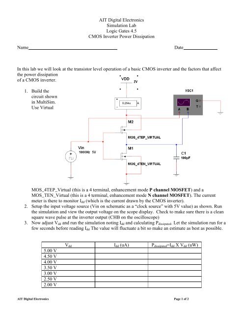
AIT Digital Electronics<br />
Simulation Lab<br />
Logic Gates 4.5<br />
CMOS Inverter Power Dissipation<br />
Name<br />
Date<br />
In this lab we will look at the transistor level operation of a basic CMOS inverter and the factors that affect<br />
the power dissipation<br />
of a CMOS inverter.<br />
1. Build the<br />
circuit shown<br />
in MultiSim.<br />
Use Virtual<br />
MOS_4TEP_Virtual (this is a 4 terminal, enhancement mode P channel MOSFET) and a<br />
MOS_TEN_Virtual (this is a 4 terminal, enhancement mode N channel MOSFET). The current<br />
meter is there to monitor I dd (which is the current drawn by the CMOS inverter).<br />
2. Setup the input voltage source (Vin on schematic as a “clock source” with 5V value) as shown. Run<br />
the simulation and view the output voltage on the scope display. Check to make sure there is a clean<br />
square wave pulse at the inverter output (CHB on the oscilloscope)<br />
3. Now adjust V dd and run the simulation noting I dd and calculating P dissipated . Let the simulation run for a<br />
few seconds before reading I dd The value will fluctuate a bit so make an estimate as best as possible.<br />
5.00 V<br />
4.50 V<br />
4.00 V<br />
3.50 V<br />
3.00 V<br />
2.50 V<br />
2.00 V<br />
V dd I dd (uA) P dissipated =I dd X V dd (uW)<br />
AIT Digital Electronics Page 1 of 2
4. Using Excel plot P dissipated vs. V dd .<br />
If you were to write an equation for this curve/line, would P dissipated be a function of V or V 2 ?<br />
5. Now set V dd back to 5.0 V and run the simulation while varying the Vin frequency as the dependent<br />
parameter. Note I dd and calculate P dissipated as before.<br />
Vin Frequency f (Hz) I dd (uA) P dissipated =I dd X V dd (uW)<br />
1000<br />
10000<br />
100000<br />
6. Using Excel plot P dissipated vs. V in frequency (f).<br />
7. If you were to write an equation for this curve/line, would P dissipated be a function of f or f 2 ?<br />
8. Based on your analysis, comment on the effect of clock speed (frequency) and power supply voltage (V dd )<br />
on the power dissipation for a large multi-gate CMOS IC.<br />
AIT Digital Electronics Page 2 of 2