PM 819 ⦠- Pietro Fiorentini
PM 819 ⦠- Pietro Fiorentini
PM 819 ⦠- Pietro Fiorentini

Create successful ePaper yourself
Turn your PDF publications into a flip-book with our unique Google optimized e-Paper software.
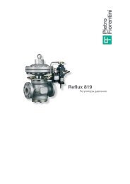
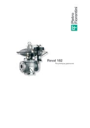
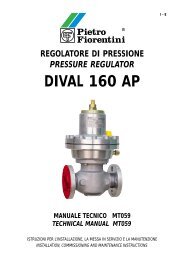
REDUKTOR CIŚNIENIA<br />
PRESSURE REGULATOR<br />
REFLUX <strong>819</strong><br />
CT 238-a./PL/E
P<br />
CIŚNIENIE WLOTOWE<br />
INLET PRESSURE<br />
REDUKTOR CIŚNIENIA GAZU PRESSURE REGULATOR<br />
REFLUX <strong>819</strong> + DB <strong>819</strong> + 204/A + R14/A<br />
DB <strong>819</strong><br />
REFLUX <strong>819</strong><br />
…+SB 82<br />
L<br />
CIŚNIENIE WYLOTOWE<br />
OUTLET PRESSURE<br />
CIŚNIENIE POŚREDNIE<br />
PILOT FEED<br />
2<br />
R14/A<br />
<strong>PM</strong> <strong>819</strong><br />
CIŚNIENIE STERUJĄCE<br />
MOTORIZATION<br />
204/A<br />
…+<strong>PM</strong> <strong>819</strong><br />
CIŚNIENIE STERUJĄCE<br />
MOTORIZATION<br />
R14/A
WSTĘP INTRODUCTION<br />
Reflux <strong>819</strong> jest reduktorem ciśnienia sterowanym pilotem<br />
do średnich i wysokich wartości ciśnienienia (Rys. 1).<br />
Reduktory te mogą być stosowane do uprzednio<br />
przefiltrowanych gazów niekorozyjnych.<br />
- Ciśnienie obliczeniowe: do 100 bar<br />
- Temperatura obliczeniowa: -10 +50°C (inne wartości<br />
temperatury na żądanie)<br />
- Temperatura otoczenia: -20 +60°C<br />
- Zakres ciśnienia wlotowego bpe: 0,5÷85 bar<br />
- Zakres regulacji ciśnienia wylotowego Wh: 0,3-60 bar<br />
(w zależności od zainstalowanego pilota)<br />
- minimalna robocza różnica ciśnienia: 0,5 bar<br />
- Klasa dokładności RG:1<br />
- Klasa ciśnienia zamknięcia SG: od 3 do 1, zależnie<br />
od ciśnienia wylotowego<br />
- Dostępne rozmiary DN 1 - 2 - 3 - 4 - 6 - 8 - 10"<br />
- Kołnierze klasa: 150-300-600 RF lub RTJ zgodnie<br />
z ANSI B16.5 i PN 16 zgodnie z UNI 2282 lub 2263<br />
Modułowa budowa reduktorów ciśnienia Reflux <strong>819</strong><br />
pozwala na zastosowanie monitora awaryjnego <strong>PM</strong> <strong>819</strong><br />
normalnie zamkniętego lub zaworu szybkozamykającego<br />
i tłumika w tym samym korpusie bez zmiany wymiaru<br />
między powierzchniami czołowymi kołnierzy również<br />
po zainstalowaniu reduktora. Ponadto budowa z dostępem<br />
od góry umożliwia przeprowadzenie konserwacji<br />
okresowej bez potrzeby demontowania korpusu<br />
z gazociągu.<br />
Rys.1<br />
CHARAKTERYSTYKA PODSTAWOWA MAIN FEATURES<br />
3<br />
Reflux <strong>819</strong> is pilot-controlled pressure regulator for<br />
medium and high pressure (Fig. 1).<br />
These regulators are suitable for use with previously<br />
filtered, non corrosive gases.<br />
- Design pressure: up to 100 bar<br />
- Design temperature: -10 +50°C (lower and upper<br />
temperature available on request)<br />
- Ambient temperature: -20 +60°C<br />
- Range of inlet pressure bpe: 0.5÷85 bar<br />
- Range of outlet pressure Wh: 0.3-60 bar (depending<br />
on installed pilot)<br />
- Minimum working differential pressure: 0.5 bar<br />
- Accuracy class RG: up to 1<br />
- Closign pressure class SG: from 3 to 1 depending<br />
on outlet pressure<br />
- Available size DN: 1” -2” -3” -4” -6” -8” -10”<br />
- Flanging: class 150-300-600 RF or RTJ according<br />
to ANSI B16.5 and PN16 according to UNI 2282<br />
or DIN 2263.<br />
Modular design of pressure regulators Reflux <strong>819</strong><br />
allows application of an emergency monitor “fail to<br />
close” <strong>PM</strong> <strong>819</strong> or a slam shut and silencer on the<br />
same body without changing the face-to-face<br />
dimensions also after the installation of regulator.<br />
Furthermore “top entry design” allows an easy<br />
periodical maintenance without removing body from<br />
pipeline.
MATERIAŁY- MATERIALS<br />
Korpus Odlew staliwny ASTM A352 LCB dla klasy 300 i 600<br />
ASTM A 216 WCB dla klasy 150 i PN 16<br />
Body Cast steel ASTM A352 LCB for class 300 and 600<br />
ASTM A216 WCB for class 150 and PN16<br />
Pokrywa Stal nierdzena<br />
Cover Stainless steel AISI 416<br />
Trzpień Stal nierdzewna<br />
Stem Stainless steel<br />
Zawieradło AISI 303 dla DN≤3". chromowana stal węglowa z brzegiem<br />
uszczelniającym ze stali nierdzewnej dla DN≥4"<br />
Plug AISI 303 for DN≤3”<br />
Chromium plated carbon steel with seal edge in stainless steel for DN≥4”<br />
Gniazdo zaworu Stal + guma wulkanizowana<br />
Sealing Steel + vulcanized rubber<br />
Uszczelnienie Guma nitrylowa<br />
Sealing Nitril rubber<br />
Złączki ściskowe DIN 2353 z ocynkowanej elektrolitycznie stali węglowej<br />
Compression fittings According to DIN 2353 in zinc plated carbon steel<br />
Powyższy opis dotyczy wersji standardowej. Specjalne cechy<br />
charakterystyczne i materiały do zastosowań specjalnych są<br />
dostępne na zamówienie.<br />
WYBÓR REDUKTORA CIŚNIENIA MAIN FEATURES<br />
Wyboru rozmiaru reduktora dokonuje się zazwyczaj<br />
na podstawie współczynnika Cg zaworu oraz współczynnika<br />
przepływu KG (tablica 1).<br />
Przepływ w położeniu całkowicie otwartym w różnych warunkach<br />
roboczych jest opisany przedstawionymi poniżej wzorami, gdzie:<br />
Q = przepływ w Nm 3 /h<br />
Pe = ciśnienie wlotowe w bar<br />
Pa=ciśnienie wylotowe w bar<br />
A - w przypadku gdy wartości Cg iKG reduktora<br />
oraz wartości Pe i Pa są znane:<br />
A-1 w w arunkach niekrytycznych: (Pe
B-2 w warunkach krytycznych: (Pe≥2•Pa)<br />
Argument sen powinien być wyrażony w DEG.<br />
Tab. 1 WSPÓŁCZYNNIKI Cg ORAZ KG ZAWORU - VALVE COEFFICIENTS Cg. KG<br />
Rozmiar (DN) 25 65 80 100 50 65 80 100<br />
Size (DN) 2” 2” 3” 4” 2” 2” 3” 4”<br />
Współczynnik Cg - Cg coefficien 1706 2731 3906 5490 1667 2793 4099 5660<br />
Współczynnik KG - KG coefficien 1796 2875 4112 5775 1755 2940 4315 5954<br />
Współczynnik Cg odpowiada liczbowo wartości przepływu<br />
powietrza, wyrażonego w Nm3/h, w warunkach krytycznych<br />
przy pełnym otwarciu reduktora, pracującego<br />
przy ciśnieniu przed reduktorem<br />
równym 1 psi w temperaturze<br />
15°C. Współczynnik KG odpowiada<br />
liczbowo wartości przepływu<br />
gazu ziemnego, wyrażonego w<br />
Stm/h, w warunkach krytycznych<br />
przy pełnym otwarciu reduktora<br />
pracującego przy ciśnieniu przed<br />
reduktorem równym 2 bar abs<br />
w temperaturze 15°C. Jak już<br />
wspomniano, wartości Cg i KG<br />
podane w tablicy 1, dotyczą zawieradła<br />
w pozycji całkowicie otwartej.<br />
Wykres na Rys. 2 przedstawia<br />
wartości procentowe Cg i KG jako<br />
funkcję otwarcia zawieradła.<br />
Powyższe wzory dotyczą gazu<br />
ziemnego o gęstości względnej<br />
0,61 w porównaniu z powietrzem<br />
przy temperaturze 15°C<br />
na wlocie reduktora. Dla gazów<br />
o gęstości względnej S<br />
i temperaturze t w °C obliczoną<br />
% Cg, KG<br />
w powyższy sposób wartość przepływu należy skorygować<br />
poprzez jej pomnożenie przez:<br />
W tablicy 2 przedstawiono współczynniki korygujące<br />
Fc dla różnych gazów w temperaturze 15°C.<br />
100<br />
90<br />
80<br />
70<br />
60<br />
50<br />
40<br />
30<br />
20<br />
10<br />
Tab. 2 WSPÓŁCZYNNIK KORYGUJĄCY FC - CORRECTION FACTOR FC<br />
0<br />
0<br />
10<br />
Rys. 2<br />
Coefficienti Cg e KG<br />
Valve coefficients Cg and KG<br />
5<br />
B-2 in critical conditions: (Pe>2•Pa)<br />
Then sen argument is intended in DEG.<br />
Il coefficiente Cg corrisponde numericamente al<br />
valore della portata espressa in Sft3/h di aria fornita<br />
dal regolatore completamente aperto in salto critico,<br />
con una pressione a monte di 1<br />
20 30 40 50 60 70 80 90 100<br />
Grado di apertura %<br />
Opening %<br />
p.s.i. e a temperatura di 60°F.<br />
Il coefficiente KG corrisponde<br />
numericamente al valore del<br />
flusso di gas naturale in Stm/h<br />
a 15°C con regolatore completamente<br />
aperto per una pressione<br />
di monte pari a 2 bar ed<br />
una pressione a valle di 1 bar. I<br />
valori di Cg e KG indicati in<br />
tabella 1 sono determinati con<br />
l’otturator ein posizione di massima<br />
apertura; il diagramma di<br />
Fig. 2 riporta i valori percentuali<br />
di Cg e KG a diversi gradi di<br />
apertura dell’otturatore. Le<br />
sopracitate formula sono valide<br />
per gas naturale avente densità<br />
relativa rispetto all’aria di 0.61 e<br />
temperature all’ingresso del<br />
regolatore pari a 15°C.<br />
P er gas con densità relativa S<br />
e temperatura t in °C diverse da<br />
queste, il valore della portata calcolata come sopra,<br />
deve( essere moltiplicato per un coefficiente correttivo<br />
determinato come segue:<br />
La tabella 2 riporta i fattori correttivi Fc validi per<br />
alcuni gas, calcolati alla temperatura di 15°C.<br />
Typ gazu Type of g Gęstość Względna - Specific g Współczynnik Fc - Factor Fc<br />
Powietrze Air 1.0 0.78<br />
Propan Propane 1.53 0.63<br />
Butan Butane 2.0 0.55<br />
Azot Nitrogen 0.97 0.79<br />
Tlen Oxigen 1.14 0.73<br />
Dwutlenek węgla Carbon dioxide 1.52 0.63
Uwaga: dla uzyskania prawidłowego działania, uniknięcia<br />
zjawiska erozji i ograniczenia poziomu hałasu, zaleca<br />
się ograniczenie prędkości gazu na kołnierzu wylotowym<br />
do 150 m/s. Prędkość gazu na kołnierzu wylotowym<br />
można obliczyć z poniższego wzoru:<br />
dove:<br />
V = prędkość gazu w m/s<br />
Q = przepływ gazu Nm3/h<br />
DN = rozmiar nominalny reduktora w mm<br />
p = ciśnienie wylotowe w bar.<br />
W celu szybkiego obliczenia przepływu, patrz tab. 4<br />
gdzie przedstawiono wydajności obliczone dla różnych<br />
warunków roboczych.<br />
UKŁAD PILOTÓW PILOT SYSTEM<br />
- Piloty<br />
Reduktory Reflux <strong>819</strong> są wyposażone w piloty z serii<br />
200 zgodnie z poniższą specyfikacją:<br />
- 204/. zakres regulacji ciśnienia Wh: 0,3÷43 bar;<br />
- 205/. zakres regulacji ciśnienia Wh: 20÷60 bar;<br />
Piloty mogą być regulowane ręcznie lub zdalnie,<br />
zgodnie z wyszczególnieniem w tablicy 3:<br />
Tab. 3 SPOSOBY REGULACJI PILOTÓW - PILOT ADJUSTING INSTRUCTIONS<br />
Typ pilota- Pilot type Rodzaj sterowania - Control type<br />
- Pilot wstępny<br />
Układ pilotów musi być uzupełniony pilotem wstępnym<br />
oddzielonym od pilota zasadniczego. Dostępne są<br />
następujące piloty wstępne:<br />
- R14: bez regulacji; ciśnienie zasilania do pilota zasadniczego<br />
zwiększa się samoczynnie;<br />
- R34: z regulowaną wartością zadaną (Wh: 1,2÷45 bar).<br />
Oba te piloty są wyposażone w filtr wbudowany.<br />
- Akcesoria<br />
Układ pilotów może być uzupełniony poniższymi<br />
akcesoriami:<br />
- dodatkowy filtr CF14;<br />
- filtr odwadniający;<br />
- zawór nadmiarowy VSFI (wykorzystywany z pilotem<br />
wstępnym R34);<br />
- urządzenia do ograniczenia przepływu.<br />
na Rys. 3 przedstawiono schemat układu pilotów.<br />
Caution: to obtain good performance, to avoid erosion<br />
pohenomena and to limit noise level, it is recommended<br />
to limit gas speed on outlet flange to 150 m/sec.<br />
Gas speed on outlet flange may be calculated with following<br />
formula:<br />
where:<br />
V = gas speed in m/sec<br />
Q = gas flow in Stm/h<br />
DN = nominal size of regulator in mm<br />
p = outlet pressure in barg.<br />
For a quick calculation of flow rate see table 4 where<br />
capacities calculated in various working conditions are<br />
indicated.<br />
- Pilots<br />
Reflux <strong>819</strong> regulators are equipped with pilot series<br />
200 as below listed:<br />
- 204/. set pressure range Wh: 0.3 to 43 bar;<br />
- 205/. set pressure range wh: 20 to 60 bar;<br />
Pilots may be adjusted manually or by remote control<br />
as listed in table 3:<br />
.../A Ręczna regulacja - Manual setting<br />
.../ Zdalna elektryczna regulacja - Electric remote setting control<br />
.../C Regulacja za pomocą sygnału pneumatycznego - Setting increased by pneumatic signal from remote point<br />
6<br />
- Preregulator<br />
Pilot system must be completed with preregulator<br />
separated from pilot.<br />
Below listed preregulators are available:<br />
- R14 not adjustable; the feeding pressure to pilot is<br />
self increased;<br />
- R34 with adjustable set point (Wh: 1.2 to 45 bar).<br />
Both these regulators are equipped with incorporated<br />
filter.<br />
- Accesory<br />
Pilot system may be completed with below listed<br />
accessory:<br />
- supplementary filter CF14;<br />
- deydrator filter;<br />
- relief valve VSFI (employed with R34 preregulator);<br />
- devices for flow limitation.<br />
Fig. 3 shows a pilot system schema.
Rys. 3<br />
Ciśnienia - Pressions<br />
Wlotowe - Inlet<br />
Wylotowe - Outlet<br />
Zasilające - Pilot feed<br />
Sterujące - Motorization<br />
ZAWÓR MIKROPRZEPŁYWOWY "FLUID CONTROL" 896 MICROFLOW VALVE FLUID CONTROL 896<br />
W przypadku, gdy konieczne jest zastosowanie reduktora<br />
Reflux w obwodzie regulacyjnym procesu, możliwe<br />
jest pilotowanie tego reduktora za pomocą zaworu<br />
mikroprzepływowego typu "fluid control" 896, sterowanego<br />
sygnałem 3 - 15 psi (odnośnie charakterystyki - patrz<br />
oddzielny katalog).<br />
Na rys. 4 przedstawiono schemat układu pilotów<br />
z zaworem mikroprzepływowym.<br />
pilot wstępny R14/A<br />
PRE-REGULATOR R 14/A<br />
REDUKTOR REFLUX <strong>819</strong><br />
PRESSURE REGOLATOR REFLUX <strong>819</strong><br />
pilot serii 200<br />
PILOT SERIES 200<br />
Rys. 4<br />
FLUID CONTROL 896<br />
VALVOLA MICROFLUSSO<br />
FLUIDCONTROL VALVE<br />
7<br />
pilot wstępny R14<br />
Preregolator R14<br />
When it is necessary to employ a regulator Reflux<br />
<strong>819</strong> on regulating ring of a process, it is possible to<br />
pilot this regulator with microflow valve Fluid Control<br />
896 controlled by a 3-15 psi signal (see relevant<br />
catalogue for features).<br />
Fig. 4 show a schema of pilot system with microflow<br />
valve.<br />
przetwornik elektropneumatyczny<br />
ELECTROPNEUMATIC CONVERTOR<br />
Ciśnienia - Pressions<br />
Wlotowe - Inlet<br />
Wylotowe - Outlet<br />
Pilot - Pilot<br />
204-205-206<br />
Zasilające - Pilot feed<br />
Sterujące - Motorization<br />
sterownik elektroniczny<br />
ELECTRONIC REGULTOR
WBUDOWANY TŁUMIK DB <strong>819</strong> INCORPORATED SILENCER DB <strong>819</strong><br />
Urządzenie to pozwala znacznie obniżyć poziom hałasu<br />
wywołanego redukcją ciśnienia gazu w sytuacjach, gdy<br />
problem ten może występować z uwagi na określone<br />
warunki (Rys.5).<br />
Krzywa robocza na Rys.6 predstawia skuteczność<br />
tłumika w określonych warunkach roboczych.<br />
Reduktor ciśnienia Reflux <strong>819</strong> może być dostarczony<br />
z wbudowanym tłumikiem zarówno w wersji standardowej,<br />
jak i w wersji z zaworem szybkozamykającym lub<br />
monitorem awaryjnym.<br />
Model z wbudowanym tłumikiem, podobnie jak model<br />
z monitorem awaryjnym lub zaworem szybkozamykającym<br />
posiada tę zaletę, że może on być dodany do dowolnego<br />
już zainstalowanego reduktora Reflux <strong>819</strong> bez potrzeby<br />
modyfikacji gazociągu.<br />
W przypadku wbudowanego tłumika wartość współczynnika<br />
Cg zaworu jest tylko nieco niższa od wartości<br />
dla podobnej wersji bez tłumika.<br />
Metoda redukcji ciśnienia i regulacji jest taka sama jak<br />
dla normalnego reduktora.<br />
MONITOR MONITOR<br />
Monitor jest reduktorem awaryjnym, który podejmuje<br />
działanie, jeżeli reduktor główny dopuści do wzrostu<br />
ciśnienia za reduktorem do wartości ciśnienia zadanej<br />
dla monitora. Dla spełnienia tych wymagań można<br />
wprowadzić dwa alternatywne rozwiązania:<br />
- monitor wbudowany,<br />
- monitor szeregowy.<br />
8<br />
dBa<br />
50<br />
0<br />
This device permits a considerable reduction in the<br />
level of noise produced by the gas pressure reducing<br />
whenever it may be a problem because of particular<br />
conditions (Fig. 5).<br />
Curve in Fig. 6 shows the efficiency of silencer in<br />
specified working conditions.<br />
The Reflux <strong>819</strong> pressure regulator cna be supplied<br />
with an incorporated silencer in both the standard<br />
version, with slam shut or with emergency monitor.<br />
The incorporated-silencer model, like the one with<br />
the emergency monitor or slum shut, has the advantage<br />
that it can be added to any Reflux <strong>819</strong> already<br />
installed without needing to alter the piping.<br />
With built-in silencer the Cg valve coefficient is only<br />
slightly lower than the corresponding version<br />
without silencer.<br />
The pressure reduction and adjustment method is<br />
the same as for the normal regulator.<br />
Przepływ - Flow rate<br />
Rys.5 Rys.6<br />
Poziom hałasu Noise level<br />
120<br />
110<br />
100<br />
90<br />
80<br />
70<br />
60<br />
bez tłumika - Not silenced<br />
z tłumikiem - Silenced<br />
Aperval Dn 2”<br />
Pe = 16 bars<br />
Pa = 0,1 Bars<br />
5 10 15 20 25 30 35<br />
Stm 3 /h x 1000<br />
The monitor is an emercency regulator which comes<br />
itno operation if main regulator allows downstream<br />
pressure to increase up to monitor set pressure.<br />
To fulfil these requirements two alternative solutions<br />
may be introduced: an incorporated monitor or an<br />
in-line monitor.
MONITOR WBUDOWANY Z SERII <strong>PM</strong> <strong>819</strong> <strong>PM</strong><strong>819</strong> SERIES INCORPORATED MONITOR<br />
W tym przypadku reduktor awaryjny (monitor) jest montowany<br />
bezpośrednio na korpusie redyktora głównego (Rys.7).<br />
W ten sposób oba reduktory ciśnienia<br />
wykorzystują ten sam korpus zaworu<br />
jednakże:<br />
- kierują nimi dwa oddzielne piloty<br />
i oddzielne siłowniki<br />
- pracują one na niezależnych<br />
gniazdach zaworu w tym samym<br />
korpusie<br />
Współczynniki Cg/KG układów<br />
złożonych z:<br />
- reduktora Reflux <strong>819</strong>;<br />
- wbudowanego monitora <strong>PM</strong> <strong>819</strong><br />
odpowiadają około 93% wartości<br />
standardowej dla reduktora<br />
Reflux <strong>819</strong>. Dużą zaletą opisanego<br />
rozwiązania jest to, że monitor<br />
<strong>PM</strong> <strong>819</strong> może być zastosowany<br />
na już zainstalowanym standardowym<br />
reduktorze Reflux <strong>819</strong> bez<br />
potrzeby modyfikacji gazociągu.<br />
MONITOR SZEREGOWY<br />
W tym rozwiązaniu monitor jest instalowany przed<br />
reduktorem głównym.<br />
Mimo odmiennej funkcji oba urządzenia są praktycznie<br />
identyczne z punktu widzenia komponentów mechanicznych<br />
i elementów uszczelniających. Monitor ma<br />
jedynie wyższą wartość zadaną ciśnienia niż reduktor<br />
główny.<br />
Współczynniki Cg/KG układu reduktora z monitorem<br />
liniowym są około 20% mniejsze niż dla samego<br />
reduktora.<br />
PILOT PRZYŚPIESZAJĄCY M/A<br />
W przypadku zastosowania monitora w postaci reduktora<br />
Reflux <strong>819</strong> lub monitora wbudowanego <strong>PM</strong> <strong>819</strong> czas<br />
reakcji monitora, wynikającej z nieprawidłowego<br />
działania reduktora<br />
głównego, może być przyspieszony<br />
poprzez zainstalowanie na reduktorze<br />
awaryjnym zaworu przyspieszającego<br />
M/A (Rys.8). W oparciu o sygnał<br />
ciśnienia za reduktorem urządzenie<br />
to wypuszcza gaz z komory uruchamiającej<br />
monitora, umożliwiając<br />
szybszą interwencję monitora.<br />
Wartość zadana pilota M/A musi<br />
być wyższa od wartości zadanej<br />
monitora o 0,3 do 0,5 bar.<br />
Rys. 7<br />
Rys. 8<br />
URUCHAMIANIE<br />
MOTORIZATION<br />
WYLOT<br />
EXHAUST<br />
9<br />
In this case the emrcency regulator (monitor) is<br />
directly assembled to the body of main regulator<br />
(Fig. 7).<br />
Both pressure regulators,<br />
therefore, use same valve body<br />
but:<br />
- they are governed by two different<br />
pilots and by separate<br />
servomotors;<br />
- they operate on different valve<br />
seats on same body.<br />
The Cg/KG coefficients of the<br />
system composied by:<br />
- Reflux <strong>819</strong>;<br />
- <strong>PM</strong> <strong>819</strong> incorporate monitor<br />
are approximately 93% of standard<br />
Reflux <strong>819</strong> coefficients.<br />
Abig advantage of described<br />
solution is that application of<br />
the <strong>PM</strong> <strong>819</strong> incorporated monitor<br />
can be done on a standard<br />
Reflux <strong>819</strong> already installed,<br />
without any alternations to the<br />
pipeline.<br />
IN LINE MONITOR<br />
In this solution, the monitor is installed upstream<br />
main regulator.<br />
Though they have different functions, the two devices<br />
are virtually identical from the point of view of<br />
their mechanical components and sealing organs.<br />
The monitor only has a higher pressure setting than<br />
the main regulator.<br />
The Cg and KG coefficients of the regulator system<br />
with in-line monitor are about 20% lower than for<br />
the regulator alone.<br />
M/A ACCELERATOR<br />
When as monitor the regulator Reflux <strong>819</strong> or incorporated<br />
monitor <strong>PM</strong> <strong>819</strong> are used, the response<br />
time of monitor, due to faulty<br />
operation of main regulator,<br />
CIŚNIENIE ZA REDUKTOREM<br />
DOWNSTREAM PRESSURE<br />
can be accelerated by rinstalling<br />
the M/A accelerator on the<br />
emergency regulator (Fig. 8).<br />
Based on downstream pressure<br />
signal, this device exhausts<br />
gas from monitor motorization<br />
chamber allowing a more rapid<br />
intervention of monitor.<br />
M/A accelerator setting must<br />
be higher than monitor’s one by<br />
O.3 to 0.5 bar.
ZAWÓR SZYBKOZAMYKAJĄCY SLAM SHUT<br />
Jest to urządzenie, które niezwłocznie blokuje przepływ<br />
gazu (SAV), gdy ciśnienie za reduktorem osiągnie wartość<br />
zadaną dla jego interwencji. Urządzenie to może<br />
być również aktywowane poprzez naciśnięcie przycisku.<br />
WBUDOWANY ZAWÓR SZYBKOZAMYKAJĄCY SB 82<br />
Zawór szybkozamykający SB 82 może być wbudowany<br />
na monitorze lub reduktorze głównym Reflux <strong>819</strong>(Rys.9).<br />
Wartości współczynników Cg/KG układu złożonego z:<br />
- reduktora Reflux <strong>819</strong>;<br />
- wbudowanego zaworu szybkozamykającego SB 82;<br />
wynoszą około 93% wartości standardowej dla reduktora<br />
Reflux <strong>819</strong>. Zawór szybkozamykający SB 82 może być<br />
zamontowany na już zainstalowanych reduktorach<br />
Reflux <strong>819</strong> bez potrzeby modyfikacji gazociągu.<br />
Podstawowa charakterystyka tego urządzenia jest<br />
następująca:<br />
- dokładność (AG): ±0,5% wartości zadanej ciśnienia;<br />
- interwencja w przypadku wzrostu ciśnienia i/lub spadku;<br />
- sterowanie ręczne za pomocą przycisku;<br />
- opcja pneumatycznego lub elektromagnetycznego<br />
sterowania zdalnego;<br />
- ręczne ponowne nastawienie z wewnętrznym obejściem<br />
aktywowanym dźwignią sterującą;<br />
- niewielkie wymiary gabarytowe;<br />
- łatwa konserwacja;<br />
- możliwość zastosowania urządzeń do interwencji<br />
na sygnał zdalny (przełączniki kontaktowe lub<br />
zbliżeniowe).<br />
W tablicy 4 przedstawiono dostępne siłowniki<br />
ciśnieniowe.<br />
Rys.10<br />
This device immediately stops gas flow (SAV) if<br />
downstream pressure rises up tis pressure set. This<br />
device can also be activated pressing a push button.<br />
INCORPORATED SLAM SHUT SB 82<br />
SB 82 can be incorporated on monitor or on main<br />
Reflux <strong>819</strong> regulator (Fig. 9). The Cg/KG coefficients<br />
of the system composed by:<br />
- Reflux <strong>819</strong>;<br />
- SB 82 incorporated slam shut.<br />
Are about 93% of standard Reflux <strong>819</strong> coefficients.<br />
Application of the SB 82 slam shut can be done to<br />
the reflux <strong>819</strong> regulators already installed without<br />
any alternations to the pipeline.<br />
Main characteristics of this device are:<br />
- accuracy: (AG) ±0.5 on the value of the pressure<br />
setting;<br />
- intervention on pressure increase and/or decrease-<br />
manual push-botton control;<br />
- option for pneumatic or electromagnetic remote<br />
control;<br />
- manual re-setting with internal by-pass activated<br />
by the manoeuvering lever;<br />
- small overall size;<br />
- easy maintenance;<br />
- possibility of application of devices for intervention<br />
remote signal (contact switches or proximity switches).<br />
Table 4 draws the available pressure switches.<br />
Tab.4 SIŁOWNIKI CIŚNIENIOWE ZAWORU SZYBKOZAMYKAJĄCEGO<br />
PRESSURE SWITCHES FOR SLAM SHUT<br />
Siłowniki - Pressure switch 102 103 104 105<br />
Zakres regulacji dla wzrostu Pmax<br />
Setting range for increase of Pmax<br />
Ciśnienie robocze w bar 0,2÷5 2÷22 15÷44 30÷88<br />
Working pressure in bar Zakres regulacji dla spadku w Pmin<br />
Setting range for decrease of Pmin<br />
0,04÷0,7 0,2÷4 1,6÷8 3,2÷16<br />
Siłowniki - Pressure switch 106 107 108 109<br />
Zakres regulacji dla wzrostu Pmax<br />
Setting range for increase of Pmax<br />
Ciśnienie robocze w bar 45÷5 4÷22 15÷44 30÷88<br />
Working pressure in bar Zakres regulacji dla spadku Pmin<br />
Setting range for decrease of Pmin<br />
10<br />
0,5÷5 3,5÷22 7÷44 14÷88
INSTALACJA<br />
W celu uzyskania prawidłowego działania reduktora<br />
Reflux <strong>819</strong> podczas instalacji należy zachować pewne<br />
zalecenia, dotyczące obwodu głównego i przewodu<br />
zasilającego piloty:<br />
a) Filtrowanie: gaz dopływający z rurociągu głównego<br />
musi być odpowiednio przefiltrowany; zaleca się<br />
również, by gazociąg przed reduktorem był absolutnie<br />
czysty i nie zawierał resztek zanieczyszczeń.<br />
b) Ogrzewanie wstępne: zawsze gdy spadek ciśnienia<br />
na reduktorze jest znaczny, konieczne jest ogrzewanie<br />
gazu w stopniu wystarczającym dla uniknięcia<br />
skraplania substancji ciekłej i stałej podczas dekompresji<br />
(należy pamiętać, że dla metanu gazowego<br />
spadek temperatury wynosi około 0,4÷0.5°C dla<br />
każdego spadku ciśnienia na reduktorze o 1 bar);<br />
c) Kolektor kondensatu: gaz ziemny zawiera czasami<br />
ślady węglowodorów w postaci oparów, które mogą<br />
zakłócić prawidłowe działanie pilota; dlatego też<br />
przed przewodem zasilającym reduktora wstępnego<br />
należy zainstalować kolektor kondensatu i układ<br />
jego odwadniania.<br />
d) Punkt poboru impulsów ciśnienia: dla prawidłowego<br />
działania punkt poboru impulsów ciśnienia musi być<br />
prawidłowo umieszczony. Między reduktorem<br />
a punktem poboru impulsów ciśnienia za urządzeniem<br />
odcinek rurociągu musi mieć długość minimum<br />
czterech średnic rurociągu wylotowego; odcinek<br />
rurociągu za punktem poboru impulsów ciśnienia<br />
musi mieć długość minimum dwóch średnic rurociągu<br />
wylotowego.<br />
To operate correctly Reflux <strong>819</strong> regulator, certain<br />
specifications must be followed during installation<br />
with regard to the main circuit and the pilot supply<br />
pipe.<br />
These rules may be summarized as follows:<br />
a) filtering: the fgas arriving from the main pipeline<br />
must be adeguately filtered; it is also advisable to<br />
make sure that the pipe upstream from the regulator<br />
is perfectely clean and avoid residual impuries;<br />
b) pre-heating: whenever the pressure drop at the<br />
regualtor is considerable, the gas must be heated<br />
enough to avoid liquid and solid hydrated<br />
during decompression (bear in mind that for<br />
methane gas the temperature drop is about<br />
0.4÷0.5°C ffor every bar of pressure reduction<br />
from upstream to downstream of the pressure<br />
regulator);<br />
c) condensation collector: natural gas sometimes<br />
contains traces of vapour-state hydrocarbons<br />
that can interfere be fitted upstream from the<br />
preregulator supply line;<br />
d) impulse take-off: for correct operation, the impulse<br />
take-off must be in the right position. Between<br />
the regulator and the downstream take-off there<br />
must be a lenght of pipe ≥ four times the diameter<br />
of the outlet pipe; beyond the take-off, there<br />
must be a further lenght of pipe ≥ twice the same<br />
diameter.<br />
SCHEMATY INSTALACJI INSTALLATION SCHEMES<br />
R14/A/S<br />
R14/A/S<br />
R14/A<br />
REFLUX <strong>819</strong><br />
SB 82<br />
204/A<br />
11<br />
R14/A<br />
REFLUX <strong>819</strong><br />
SBC 82 SB82<br />
204/A<br />
Ciśnienia - Pressions<br />
Wlotowe - Inlet<br />
Wylotowe - Outlet<br />
Sterujące - Control<br />
Zasilające - Pilot feed
R14/A/S<br />
R14/A/S<br />
OPIS PRZY ZAMAWIANIU ORDERING DESCRIPTION<br />
Przy zamawianiu należy posłużyć się poniższym opisem:<br />
- Reduktor<br />
Reflux <strong>819</strong> - rozmiar i typ kołnierzy - ciśnienie przed<br />
reduktorem (bar) - ciśnienie za reduktorem (bar)<br />
- przepływ (Nm3/h) - rodzaj gazu.<br />
Przykład: reflux <strong>819</strong> - DN 2" - ANSI 600 RF - Pe = 60<br />
do 40 - Pa = 10 - Q = 10.000 - gaz ziemny.<br />
- Monitor<br />
Przy zamawianiu monitora szeregowego należy podać<br />
taki sam opis, jak dla reduktora standardowego.<br />
Dla monitora wbudowanego należy podać następujący<br />
opis: wbudowany monitor <strong>819</strong> - rozmiar - klasa ciśnienia<br />
- ciśnienie za reduktorem w bar.<br />
Przykład: <strong>PM</strong> <strong>819</strong> - DN 2" - ANSI 600 - Pa 11.<br />
R14/A<br />
R14/A<br />
REFLUX <strong>819</strong><br />
<strong>PM</strong> <strong>819</strong><br />
R14/A<br />
204/A<br />
204/A<br />
204/A<br />
REFLUX <strong>819</strong> REFLUX <strong>819</strong><br />
12<br />
M/A<br />
M/A<br />
R14/A<br />
Ciśnienia - Pressions<br />
204/A<br />
Wlotowe - Inlet<br />
Wylotowe - Outlet<br />
Sterujce - Control<br />
Zasilajce - Pilot feed<br />
Following description for order is reccomanded:<br />
- Regulator<br />
Reflux <strong>819</strong> - size and type of flange - upstream pressure<br />
(bar) - downstream pressure (bar) - flow rate<br />
(Nm3/h) - type of gas.<br />
Example: Reflux <strong>819</strong> - DN 2” - ANSI 600 RF - Pe =<br />
60 to 40 - Pa = 10 - Q = 10.000 - natural gas.<br />
- Monitor<br />
When ordering the in-line monitors, use the same<br />
description as for the standard regulator.<br />
For the incorporated monitors use the following<br />
description:<br />
incorporated monitor <strong>819</strong> - size - pressure class<br />
downstream pressure in bar.<br />
Example: <strong>PM</strong> <strong>819</strong> - DN 2” - ANSI 600 - Pa = 11.
- Zawór szybkozamykający<br />
SB 82 - rozmiar i klasa ciśnienia - model siłownika<br />
- wartość Pmin w bar - wartość Pmax w bar.<br />
Przykład: SB 82 - DN 2" - ANSI 600 - mod. 103 - Pmax 11<br />
(bez interwencji przy spadku ciśnienia).<br />
- Wbudowany tłumik<br />
Tłumik wbudowany <strong>819</strong> - klasa ciśnienia.<br />
Przykład: DB <strong>819</strong> - DN 2" - ANSI 600.<br />
- Piloty<br />
Pilot 20../... - wartość zadana w bar - wymagany zakres<br />
regulacji ciśnienia (w bar).<br />
Przy zamawianiu części zamiennych należy podać<br />
dodatkowo numer seryjny urządzenia.<br />
13<br />
- Incorporated slam-shut<br />
SB 82 - size and class pressure switch model - setting<br />
of min P in bar - setting of maximum P in bar.<br />
Example: SB 82 - DN 2” -ANSI 600 - mod. 103 -<br />
max P 11 (no intervention for pressure reduction).<br />
- Incorporated silencer<br />
Incorporated silencer <strong>819</strong> size pressure class.<br />
Example: DB <strong>819</strong> - DN 2” - ANSI 600.<br />
- Pilots<br />
20./. Pilot - setting in bar - required range for regulated<br />
pressure (in bar).<br />
Example: 204/A Pilot - Pas =10 - Wa = 8 to 12.<br />
When spare parts are ordered, serial number must<br />
be added.<br />
TAB. 5 - TABLICA WYDAJNOŚCI TAB. 5 - CAPACITY TABLE<br />
Reduktor Reflux - Regulator Reflux DN = 25 mm Cg = 575<br />
Ciśnienie wlotowe<br />
Inlet pressure (barg)<br />
1.30<br />
5.00<br />
12.00<br />
16.00<br />
20.00<br />
24.00<br />
35.00<br />
45.00<br />
50.00<br />
65.00<br />
70.00<br />
80.00<br />
Ciśnienie wylotowe - Outlet pressure (barg)<br />
0.80 2.00 4.00 8.00 9.50 15.00 20.00 30.00 43.00 65.00<br />
455<br />
1<strong>819</strong> 1760 1253<br />
3936 3936 3936 3381 2626<br />
5146 5146 5146 4927 4601 2247<br />
6335 6335 6335 6335 6099 5014<br />
7565 7565 7565 7565 7565 6803 5130<br />
10892 10892 10892 10892 10892 10892 10163 6970<br />
13917 13917 13917 13917 13917 13917 13917 12168 5272<br />
15429 15429 15429 15429 15429 15429 15429 14188 9825<br />
19966 19966 19966 19966 19966 19966 19966 19966 17570<br />
21478 21478 21478 21478 21478 21478 21478 21478 19597 10194<br />
26015 26015 26015 26015 26015 26015 26015 26015 25083 20356<br />
353 816 1366 2479 3042 4470 5928 8938 13047 20560<br />
Przepływ przy prędkości wylotowej 150 m/sec - Flow rate for outlet speed of 150 m/sec<br />
Reduktor Reflux - Regulator Reflux DN = 50 mm Cg = 2220<br />
Ciśnienie wlotowe<br />
Inlet pressure (barg)<br />
1.30<br />
5.00<br />
12.00<br />
16.00<br />
20.00<br />
24.00<br />
35.00<br />
45.00<br />
50.00<br />
65.00<br />
70.00<br />
80.00<br />
Ciśnienie wylotowe - Outlet pressure (barg)<br />
0.80 2.00 4.00 8.00 9.50 15.00 20.00 30.00 43.00 65.00<br />
1757<br />
7022 6795 4837<br />
15196 15196 15196 13053 10141<br />
19866 19866 19866 19021 17766 8674<br />
24537 24537 24537 24537 24537 19359<br />
29208 29208 29208 29208 29208 26264 19808<br />
42053 42053 42053 42053 42053 42053 39237 26911<br />
53730 53730 53730 53730 53730 53730 53730 46979 20355<br />
59569 59569 59569 59569 59569 59569 59569 54776 37934<br />
77085 77085 77085 77085 77085 77085 77085 77085 67835<br />
82923 82923 82923 82923 82923 82923 82923 82923 75661 39356<br />
100439 100439 100439 100439 100439 100439 100439 100439 96840 78594<br />
1410 3265 5464 9915 12168 17881 23714 35751 52187 82239<br />
Przepływ przy prędkości wylotowej 150 m/sec - Flow rate for outlet speed of 150 m/sec<br />
Reduktor Reflux - Regulator Reflux DN = 80 mm Cg = 4937<br />
Ciśnienie wlotowe<br />
Inlet pressure (barg)<br />
1.30<br />
5.00<br />
12.00<br />
16.00<br />
20.00<br />
24.00<br />
35.00<br />
45.00<br />
50.00<br />
65.00<br />
70.00<br />
80.00<br />
Ciśnienie wylotowe - Outlet pressure (barg)<br />
0.80 2.00 4.00 8.00 9.50 15.00 20.00 30.00 43.00 65.00<br />
3907<br />
15615 15112 10758<br />
33793 33793 33793 29027 22551<br />
44180 44180 44180 42300 39508 19290<br />
54568 54568 54568 54568 52364 43051<br />
64955 64955 64955 64955 64955 58407 44051<br />
93521 93521 93521 93521 93521 93521 87259 59848<br />
119489 119489 119489 119489 119489 119489 119489 104474 45268<br />
132474 132474 132474 132474 132474 132474 132474 121816 84361<br />
171427 171427 171427 171427 171427 171427 171427 171427 150857<br />
184411 184411 184411 184411 184411 184411 184411 184411 168260 87523<br />
223364 223364 223364 223364 223364 223364 223364 223364 215361 174782<br />
3610 8359 13988 254383 31150 45777 60708 91523 133599 210533<br />
Przepływ przy prędkości wylotowej 150 m/sec - Flow rate for outlet speed of 150 m/sec<br />
Przepływ w Nm 3 /h - Flow rate in Stm 3 /h<br />
Przepływ w Nm 3 /h - Flow rate in Stm 3 /h<br />
Przepływ w Nm 3 /h - Flow rate in Stm 3 /h
Reduktor Reflux - Regulator Reflux DN = 100 mm Cg = 8000<br />
Ciśnienie wlotowe<br />
Inlet pressure (barg)<br />
1.30<br />
5.00<br />
12.00<br />
16.00<br />
20.00<br />
24.00<br />
35.00<br />
45.00<br />
50.00<br />
65.00<br />
70.00<br />
80.00<br />
Ciśnienie wylotowe - Outlet pressure (barg)<br />
0.80 2.00 4.00 8.00 9.50 15.00 20.00 30.00 43.00 65.00<br />
6330<br />
25303 24488 17432<br />
54759 54759 54759 47036 36542<br />
71591 71591 71591 68543 64020 31258<br />
88423 88423 88423 88423 84852 69761<br />
105255 105255 105255 105255 105255 94644 71381<br />
151543 151543 151543 151543 151543 151543 141395 96978<br />
193623 193623 193623 193623 193623 193623 193623 169292 73353<br />
214663 214663 214663 214663 214663 214663 214663 197392 136700<br />
277783 277783 277783 277783 277783 277783 277783 277783 244451<br />
298823 298823 298823 298823 V298823 298823 298823 298823 272652 141824<br />
361943 361943 361943 361943 361943 361943 361943 361943 348974 283220<br />
5641 13061 21856 39661 48672 71526 94856 143004 208748 328958<br />
Przepływ przy prędkości wylotowej 150 m/sec - Flow rate for outlet speed of 150 m/sec<br />
Reduktor Reflux - Regulator Reflux DN = 150 mm Cg = 16000<br />
Ciśnienie wlotowe<br />
Inlet pressure (barg)<br />
1.30<br />
5.00<br />
12.00<br />
16.00<br />
20.00<br />
24.00<br />
35.00<br />
45.00<br />
50.00<br />
65.00<br />
70.00<br />
80.00<br />
Ciśnienie wylotowe - Outlet pressure (barg)<br />
0.80 2.00 4.00 8.00 9.50 15.00 20.00 30.00 43.00 65.00<br />
13141<br />
52525 50835 36186<br />
113672 113672 113672 97641 75857<br />
148613 148613 148613 142287 132898 64887<br />
183554 183554 183554 183554 176143 144815<br />
218496 218496 218496 218496 218496 196468 148177<br />
314584 314584 314584 314584 314584 314584 293519 201315<br />
401937 401937 401937 401937 401937 401937 401937 351430 152271<br />
445613 445613 445613 445613 445613 445613 445613 409761 283773<br />
576642 576642 576642 576642 576642 576642 576642 576642 507450<br />
620319 620319 620319 620319 620319 620319 620319 620319 565991 294409<br />
751348 751348 751348 751348 751348 751348 751348 751348 724427 587929<br />
12691 29387 49176 89237 109513 160933 213425 321760 469683 740155<br />
Przepływ przy prędkości wylotowej 150 m/sec - Flow rate for outlet speed of 150 m/sec<br />
Reduktor Reflux - Regulator Reflux DN = 200 mm Cg = 25933<br />
Ciśnienie wlotowe<br />
Inlet pressure (barg)<br />
1.30<br />
5.00<br />
12.00<br />
16.00<br />
20.00<br />
24.00<br />
35.00<br />
45.00<br />
50.00<br />
65.00<br />
70.00<br />
80.00<br />
Ciśnienie wylotowe - Outlet pressure (barg)<br />
0.80 2.00 4.00 8.00 9.50 15.00 20.00 30.00 43.00 65.00<br />
20521<br />
82022 79382 56507<br />
177507 177507 177507 152474 118457<br />
232070 232070 232070 222192 207529 101325<br />
286633 286633 286633 286633 275059 226138<br />
341196 341196 341196 341196 341196 306799 231389<br />
491245 491245 491245 491245 491245 491245 458351 314367<br />
627652 627652 627652 627652 627652 627652 627652 548782 237782<br />
695856 695856 695856 695856 695856 695856 695856 639871 443132<br />
900467 900467 900467 900467 900467 900467 900467 900467 792419<br />
968671 968671 968671 968671 968671 968671 968671 968671 883835 459740<br />
11732831173283 1173283 1173283 1173283 1173283 1173283 1173283 1131244 918093<br />
22562 52244 87425 158644 194689 286104 379423 572018 834992 1315831<br />
Przepływ przy prędkości wylotowej 150 m/sec - Flow rate for outlet speed of 150 m/sec<br />
Reduktor Reflux - Regulator Reflux DN = 250 mm Cg = 36525<br />
Ciśnienie wlotowe<br />
Inlet pressure (barg)<br />
1.30<br />
5.00<br />
12.00<br />
16.00<br />
20.00<br />
24.00<br />
35.00<br />
45.00<br />
50.00<br />
65.00<br />
70.00<br />
80.00<br />
Ciśnienie wylotowe - Outlet pressure (barg)<br />
0.80 2.00 4.00 8.00 9.50 15.00 20.00 30.00 43.00 65.00<br />
28902<br />
115523 111804 79587<br />
250008 250008 250008 214749 166839<br />
326856 326856 326856 312943 292292 142710<br />
403705 403705 403705 403705 387404 318502<br />
480554 480554 480554 480554 480554 432107 325898<br />
691887 691887 691887 691887 691887 691887 645558 442767<br />
884009 884009 884009 884009 884009 884009 884009 772925 334900<br />
980069 980069 980069 980069 980069 980069 980069 901218 624123<br />
12682521268252 1268252 1268252 1268252 1268252 1268252 1268252 116072<br />
13643121364312 1364312 1364312 1364312 1364312 1364312 1364312 1244826 647515<br />
16524951652495 1652495 1652495 1652495 1652495 1652495 1652495 1593286 1293076<br />
32253 81631 136601 247881 304202 447037 592848 893778 1304674 2055987<br />
Przepływ przy prędkości wylotowej 150 m/sec - Flow rate for outlet speed of 150 m/sec<br />
14<br />
Przepływ w Nm 3 /h - Flow rate in Stm 3 /h<br />
Przepływ w Nm 3 /h - Flow rate in Stm 3 /h<br />
Przepływ w Nm 3 /h - Flow rate in Stm 3 /h<br />
Przepływ w Nm 3 /h - Flow rate in Stm 3 /h
w<br />
DN<br />
WYMIARY GABARYTOWE w mm - OVERALL DIMENSIONS in mm<br />
Rozmiar<br />
(DN)<br />
25 50 80 100 150 200 250<br />
Size 1” 2” 3” 4” 6” 8” 10”<br />
Ansi 150/PN 16 184 254 298 352 451 543 673<br />
S Ansi 300 197 267 317 368 473 568 708<br />
Ansi 600 210 286 336 394 508 609 752<br />
A 320 350 430 490 650 750 800<br />
B 100 130 150 190 225 265 340<br />
C 278 278 360 360 510 510 610<br />
D 130 160 200 250 275 320 440<br />
E 310 310 320 320 420 420 470<br />
F 260 290 350 380 410 460 560<br />
G 410 430 530 600 735 850 900<br />
H 420 480 580 680 875 1015 1240<br />
P 170 200 260 290 320 370 500<br />
t Øe 10 x Øi 8 rurka impulsowa za reduktorem - Downstream sensing line<br />
u Øe 10 x Ø,8 rurka do podgrzewacza - To the heat exchanger<br />
w Øe 10 x Øi 8 rurka z podgrzewacza - From the heat exchanger<br />
z Øe 10 x Øi rurka zasilająca pilot - Pilot supply connection/Regulator motorization connection<br />
CIĘŻAR w kg - WEIGHTS in Kgf<br />
u<br />
REFLUX <strong>819</strong><br />
Ansi 150/PN16 44 61 105 146 308 408 900<br />
Ansi 300 45 62 109 156 345 470 950<br />
Ansi 600 46 64 112 165 360 495 1000<br />
W ymiary między powierzchniami czołowymi kołnierzy S zgodne z norma IEC 534-3.<br />
Face to face dimensions S according to IEC standard 534-3.<br />
C<br />
S<br />
z<br />
t t<br />
DN<br />
P<br />
G<br />
B<br />
15<br />
H<br />
A<br />
D<br />
E<br />
F
w<br />
DN<br />
WYMIARY GABARYTOWE w mm - OVERALL DIMENSIONS in mm<br />
Rozmiar<br />
(DN)<br />
25 50 80 100 150 200 250<br />
Size 1” 2” 3” 4” 6” 8” 10”<br />
Ansi 150/PN 16 184 254 298 352 451 543 673<br />
S Ansi 300 197 267 317 368 473 568 708<br />
Ansi 600 210 286 336 394 508 609 752<br />
A 320 350 430 490 650 750 800<br />
B 215 240 270 300 375 450 530<br />
C 278 278 360 360 510 510 610<br />
D 280 330 380 440 560 625 730<br />
E 310 310 320 320 420 420 470<br />
F 260 290 350 380 410 460 560<br />
G 410 430 530 600 735 850 900<br />
H 535 590 700 790 1025 1200 1330<br />
P 170 200 260 290 320 370 500<br />
t Øe 10 x Øi 8 rurka impulsowa za reduktorem - Downstream sensing line<br />
u Øe 10 x Øi 8 rurka do podgrzewacza - To the heat exchanger<br />
w Øe 10 x Øi 8 rurka z podgrzewacza - From the heat exchanger<br />
z Øe 10 x Øi 8 rurka zasilająca pilot - Pilot supply connection/Regulator motorization connection<br />
CIĘŻAR w kg - WEIGHTS in Kgf<br />
u<br />
Wymiary między powierzchniami czołowymi S zgodne z normą IEC 534-3.<br />
Face to face dimensions S according to IEC standard 534-3.<br />
C<br />
S<br />
z<br />
t<br />
t<br />
REFLUX <strong>819</strong> + SB 82<br />
t<br />
DN<br />
P<br />
G<br />
D<br />
Ansi 150/PN16 53 71 115 160 320 460 950<br />
Ansi 300 55 73 122 171 365 525 1000<br />
Ansi 600 56 75 125 180 380 550 1050<br />
H<br />
16<br />
A<br />
B<br />
E<br />
F
w<br />
u<br />
WYMIARY GABARYTOWE w mm - OVERALL DIMENSIONS in mm<br />
z<br />
DN<br />
Rozmiar<br />
(DN)<br />
25 50 80 100 150 200 250<br />
Size 1” 2” 3” 4” 6” 8” 10”<br />
Ansi 150/PN 16 184 254 298 352 451 543 673<br />
S Ansi 300 197 267 317 368 473 568 708<br />
Ansi 600 210 286 336 394 508 609 752<br />
A-B 320 350 430 490 650 750 800<br />
C 278 278 360 360 510 510 610<br />
D-G 410 430 530 600 735 850 900<br />
E 310 310 320 320 420 420 470<br />
F 260 290 350 380 410 460 560<br />
H 640 700 860 980 1300 1500 1600<br />
P 170 200 260 290 320 370 500<br />
t Øe 10 x Øi 8 rurka impulsowa za reduktorem - Downstream sensing line<br />
u Øe 10 x Øi 8 rurka do podgrzewacza - To the heat exchanger<br />
w Øe 10 x Øi 8 rurk a z podgrzewacza - From the heat exchanger<br />
z Øe 10 x Øi rurka zasilająca pilot - Pilot supply connection/Regulator motorization connection<br />
CIĘŻAR w kg - WEIGHTS in Kgf<br />
REFLUX <strong>819</strong> + <strong>PM</strong> <strong>819</strong><br />
Ansi 150/PN16 84 105 180 245 517 670 1400<br />
Ansi 300 84 106 184 255 554 731 1450<br />
Ansi 600 86 108 187 264 569 756 1500<br />
Wymiary między powierzchniami czołowymi kołnierzy S zgodnie z normą IEC 534-3.<br />
Face to face dimensions S according to IEC standard 534-3.<br />
C<br />
t z t t<br />
S<br />
C<br />
DN<br />
t<br />
P<br />
P<br />
G<br />
D<br />
17<br />
H<br />
A<br />
B<br />
K<br />
E<br />
F
WYMIARY GABARYTOWE w mm - OVERALL DIMENSIONS in mm<br />
w<br />
DN<br />
Rozmiar<br />
(DN)<br />
25 50 80 100 150 200 250<br />
Size 1” 2” 3” 4” 6” 8” 10”<br />
Ansi 150/PN 16 184 254 298 352 451 543 673<br />
S Ansi 300 197 267 317 368 473 568 708<br />
Ansi 600 210 286 336 394 508 609 752<br />
A 520 575 700 800 935 1085 1300<br />
B 100 130 150 190 225 265 340<br />
C 278 278 360 360 510 510 610<br />
D 130 160 200 250 275 320 440<br />
E 310 310 320 320 420 420 470<br />
F 425 495 615 670 795 895 1100<br />
G 610 640 785 895 1120 1250 1500<br />
H 620 705 850 990 1160 1350 1640<br />
P 370 400 505 585 690 770 1000<br />
K 220 300 330 390 480 595 730<br />
t Øe 10 x Øi 8 rurka impulsowa za reduktorem - Downstream sensing line<br />
u Øe 10 x Øi 8 rurka do podgrzewacza - To the heat exchanger<br />
w Øe 10 x Øi 8 rurka z podgrzewacza - From the heat exchanger<br />
z Øe 10 x Øi 8 rurka zasilająca pilot - Pilot supply connection/Regulator motorization connection<br />
CIĘŻAR w kg - WEIGHTS in Kgf<br />
u<br />
REFLUX <strong>819</strong> + DB <strong>819</strong><br />
Ansi 150/PN16 70 126 195 260 565 835 1280<br />
Ansi 300 72 128 204 289 608 925 1380<br />
Ansi 600 73 130 207 298 640 950 1430<br />
Wymiary między powierzchniami czołowymi kołnierzy S zgodnie z normą IEC 534-3.<br />
Face to face dimensions S according to IEC standard 534-3.<br />
C<br />
S<br />
z<br />
t t<br />
DN<br />
P<br />
18<br />
G<br />
B<br />
H<br />
A<br />
D<br />
K<br />
E<br />
F
WYMIARY GABARYTOWE w mm - OVERALL DIMENSIONS in mm<br />
w<br />
Rozmiar<br />
(DN)<br />
25 50 80 100 150 200 250<br />
Size 1” 2” 3” 4” 6” 8” 10”<br />
Ansi 150/PN 16 184 254 298 352 451 543 673<br />
S Ansi 300 197 267 317 368 473 568 708<br />
Ansi 600 210 286 336 394 508 609 752<br />
A 520 575 700 800 935 1085 1300<br />
B 215 240 270 300 375 450 530<br />
C 278 278 360 360 510 510 610<br />
D 280 330 380 440 560 625 730<br />
E 310 310 320 320 420 420 470<br />
F 425 495 615 670 795 895 1100<br />
G 610 640 785 895 1120 1250 1500<br />
H 735 815 970 1100 1310 1535 1830<br />
P 370 400 505 575 690 770 1000<br />
K 220 300 330 390 480 595 730<br />
t Øe 10 x Øi 8 rurka za reduktorem - Downstream sensing line<br />
u Øe 10 x Øi 8 rurka do podgrzewacza - To the heat exchanger<br />
w Øe 10 x Øi 8 rurk a z podgrzewacza - From the heat exchanger<br />
z Øe 10 x Øi 8 rurka zasilająca pilot - Pilot supply connection/Regulator motorization connection<br />
CIĘŻAR w kg - WEIGHTS in Kgf<br />
u<br />
DN<br />
REFLUX <strong>819</strong> + DB <strong>819</strong> +SB 82<br />
Ansi 150/PN16 79 136 205 274 577 887 1330<br />
Ansi 300 82 139 217 304 628 980 1430<br />
Ansi 600 83 141 220 313 660 1500 1480<br />
Wymiary między powierzchniami czołowymi kołnierzy S zgodnie z normą IEC 534-3.<br />
Face to face dimensions S according to IEC standard 534-3.<br />
C<br />
S<br />
z<br />
t<br />
t<br />
t<br />
t<br />
DN<br />
P<br />
G<br />
D<br />
19<br />
H<br />
A<br />
B<br />
K<br />
E<br />
F<br />
F
WYMIARY GABARYTOWE w mm - OVERALL DIMENSIONS in mm<br />
w<br />
Rozmiar<br />
(DN)<br />
25 50 80 100 150 200 250<br />
Size 1” 2” 3” 4” 6” 8” 10”<br />
Ansi 150/PN 16 184 254 298 352 451 543 673<br />
S Ansi 300 197 267 317 368 473 568 708<br />
Ansi 600 210 286 336 394 508 609 752<br />
A 520 575 700 800 935 1085 1300<br />
B 320 350 430 490 650 750 800<br />
C 278 278 360 360 510 510 610<br />
D 410 430 530 600 735 825 900<br />
E 310 310 320 320 420 420 470<br />
F 425 495 615 670 795 895 1100<br />
G 610 640 785 895 1120 1250 1500<br />
H 840 925 1130 1290 1585 1835 2100<br />
P 370 400 505 575 690 770 1000<br />
L 170 200 260 290 320 370 500<br />
K 220 300 330 390 480 595 730<br />
t Øe 10 x Øi 8 rurka impulsowa za reduktorem - Downstream sensing line<br />
u Øe 10 x Øi 8 rurka do podgrzewacza - To the heat exchanger<br />
w Øe 10 x Øi 8 rurka z podgrzewacza - From the heat exchanger<br />
z Øe 10 x Øi 8 rurka zasilająca pilot - Pilot supply connection/Regulator motorization connection<br />
CIĘŻAR w kg - WEIGHTS in Kgf<br />
u<br />
REFLUX <strong>819</strong> + DB <strong>819</strong> + <strong>PM</strong> <strong>819</strong><br />
C<br />
z t z<br />
t<br />
DN<br />
C<br />
S<br />
Ansi 150/PN16 110 170 270 359 774 1097 1780<br />
Ansi 300 112 172 267 388 783 1185 1880<br />
Ansi 600 113 174 270 397 815 1210 1930<br />
Wymiary między powierzchniami czołowymi kołnierzy S zgodnie z normą IEC 534-3.<br />
Zastrzegamy sobie prawo do zmian. Charakterystyka dostarczonych urządzeń może różnić się od dokumentacji.<br />
<strong>Pietro</strong> <strong>Fiorentini</strong> S.p.A.<br />
BIURA:<br />
60-167 POZNAŃ Polska ul. Krzepicka 17/19 telefon +48 61 868 99 96 fax +48 61 868 57 29<br />
E-mail: biuro@fiorentini-polska.pl<br />
I-36057 ARCUGNANO (VI) Italy - Via E. Fermi, 8/10 - Phone +39.0444.968511 (10 linee a.r.) - Telefax +39.0444.960468<br />
E-mail: arcugnano@fiorentini.com<br />
I-80142 NAPOLI Italy - Via B. Brin, 69 - Phone +39.081.5544308 - +39.081.5537201 - Telefax +39.081.5544568<br />
CZĘŚCI ZAMIENNE I SERWIS POSPRZEDAŻNY:<br />
60-167 POZNAŃ Polska ul. Krzepicka 17/19 telefon +48 61 868 99 96 fax +48 61 868 57 29 E-mail: biuro@fiorentini-polska.pl<br />
t<br />
t<br />
DN<br />
P<br />
L<br />
G<br />
D<br />
H<br />
A<br />
B<br />
K<br />
E<br />
F<br />
CT 238-a./PL/E<br />
I dati sono indicativi e non impegnativi. Ci riserviamo di apportare eventuali modifiche senza preavviso.<br />
The data are not binding. We reserve the right to make modification without prior notice.<br />
Edigraf srl • 03/2000