Attic Sprinklers - Tyco Fire Products
Attic Sprinklers - Tyco Fire Products
Attic Sprinklers - Tyco Fire Products

You also want an ePaper? Increase the reach of your titles
YUMPU automatically turns print PDFs into web optimized ePapers that Google loves.
Application:<br />
The Use of Specific Application <strong>Sprinklers</strong><br />
for Protecting <strong>Attic</strong>s<br />
Roger S. Wilkins<br />
Director of Engineering Services<br />
Research & Development<br />
<strong>Tyco</strong> <strong>Fire</strong> & Building <strong>Products</strong>
© 2007 <strong>Tyco</strong> <strong>Fire</strong> & Building <strong>Products</strong><br />
The products and specifications published herein are for general evaluation and reference purposes only and are subject<br />
to change by <strong>Tyco</strong> <strong>Fire</strong> & Building <strong>Products</strong> without notice. For the most up-to-date information, please visit<br />
www.tyco-fire.com. The information provided in this application paper should not be relied on as a substitute for<br />
professional advice concerning specific applications. ALTHOUGH TYCO FIRE & BUILDING PRODUCTS HAS<br />
ENDEAVORED TO ENSURE ITS ACCURACY, ALL INFORMATION HEREIN IS PROVIDED ON AN “AS<br />
IS” BASIS, WITHOUT WARRANTY OF ANY KIND, EITHER EXPRESS OR IMPLIED. Without limiting the<br />
foregoing, <strong>Tyco</strong> <strong>Fire</strong> & Building <strong>Products</strong> does not warrant the accuracy, adequacy or completeness of any such information.<br />
All users of the information provided herein assume the risk of use or reliance on such information and <strong>Tyco</strong> <strong>Fire</strong><br />
& Building <strong>Products</strong> shall not be liable for any damages for such use including, but not limited to, indirect, special, incidental<br />
or consequential damages.
Contents<br />
Introduction.. . . . . . . . . . . . . . . . . . . . . . . . . . . . . . . . . . . . . . . . . . . . . . . . . . . . 2<br />
APPLICATION EXAMPLES .. . . . . . . . . . . . . . . . . . . . . . . . . . . . . . . . . . . . . . . . . . 4<br />
EXAMPLE 1 ,.. Gable . . . . . . . up . . . to . . . 60 . . . ft. . . . wide . . . . . . . . . . . . . . . . . . . . . . . . . . . . . . . . . . 6<br />
EXAMPLE 2 ,.. Gable . . . . . . . greater . . . . . . . . . than . . . . . . 60 . . . ft. . . . up . . . . to . . . 80 . . . ft. . . . wide . . . . . . . . . . . . 10<br />
EXAMPLE 3 ,.. Hip . . . roof . . . . . . framed . . . . . . . . . with . . . . . . joist . . . . . . and . . . . . rafters . . . . . . . . . . . . . . . . . . 14<br />
EXAMPLE 4 ,.. Hip . . . roof . . . . . . framed . . . . . . . . . with . . . . . . trusses . . . . . . . . . . . . . . . . . . . . . . . . . . . . . 18<br />
EXAMPLE 5 ,.. Gable . . . . . . . roof . . . . . . with . . . . . double . . . . . . . . . shear . . . . . . . walls . . . . . . . . . . . . . . . . . . . 22<br />
EXAMPLE 6 ,.. Gable . . . . . . . roof . . . . . with . . . . . . a . . single . . . . . . . . shear . . . . . . . wall . . . . . . . . . . . . . . . . . . 26<br />
EXAMPLE 7 ,.. Main . . . . . roof . . . . . . area . . . . . . connected . . . . . . . . . . . . . to . . . gable . . . . . . . ends . . . . . . . . . . . . . 30<br />
EXAMPLE 8 ,.. Main . . . . . roof . . . . . . area . . . . . . with . . . . . . built-on . . . . . . . . . . dormers . . . . . . . . . . . . . . . . . . . . 34<br />
EXAMPLE 9 ,.. Reduced . . . . . . . . . . size . . . . attic . . . . . . over . . . . . . occupied . . . . . . . . . . . attic . . . . . . space . . . . . . . . . . 38<br />
WET PIPE VERSUS DRY PIPE SPRINKLER SYSTEMS. . . . . . . . . . . . . . . . . . 42<br />
WHEN CAN CPVC PIPE AND FITTINGS BE USED.. . . . . . . . . . . . . . . . . . . . . 44<br />
BETTER FIRE PROTECTION.. . . . . . . . . . . . . . . . . . . . . . . . . . . . . . . . . . . . . . . . . . 47<br />
WHAT ARE SPECIFIC APPLICATION SPRINKLERS.. . . . . . . . . . . . . . . . . . . . 51<br />
CONCLUSION .. . . . . . . . . . . . . . . . . . . . . . . . . . . . . . . . . . . . . . . . . . . . . . . . . . . . . . 52<br />
ABOUT THE AUTHOR.. . . . . . . . . . . . . . . . . . . . . . . . . . . . . . . . . . . . . . . . . . . . . . . 53<br />
Appendix A.. (TFP610) . . . . . . . . . . . . . . . . . . . . . . . . . . . . . . . . . . . . . . . . . . . . . . . . . . . . . . . 55<br />
Appendix B (Installation of Standard Spray <strong>Sprinklers</strong> .<br />
Under a Roof or Ceiling in Combustible .<br />
Concealed Spaces per NFPA 13) .. . . . . . . . . . . . . . . . . . 83
Introduction<br />
<strong>Fire</strong> sprinkler protection for attic spaces represents a unique challenge – both in sprinkler placement<br />
and fire control. Quite often unique challenges are best addressed by the use of specific application<br />
sprinklers. <strong>Tyco</strong> <strong>Fire</strong> & Building <strong>Products</strong> (TFBP) offers the <strong>Tyco</strong>® Peak Performance Model<br />
BB (Back to Back), SD (Single Directional), HIP, and AP (<strong>Attic</strong> Plus) “Specific Application<br />
<strong>Sprinklers</strong> for Protecting <strong>Attic</strong>s”. These sprinklers are specifically intended for use in combustible and<br />
non-combustible sloped attic spaces and have been developed to produce unique water spray patterns<br />
to enhance sprinkler placement while improving fire control.<br />
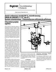
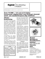
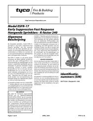
When compared to Standard Spray <strong>Sprinklers</strong> which have restricted NFPA 13 installation criteria<br />
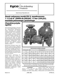
within attic spaces, the Models BB, SD, HIP, and AP <strong>Sprinklers</strong> (Fig. 1) provide:<br />
- installation with fewer sprinklers<br />
- installation with fewer branch lines<br />
- a hydraulic advantage<br />
- reduction in system volume to help quicken water delivery time for dry pipe systems<br />
- the ability to use of CPVC pipe and fittings within the attic spaces, as well as for the sprinklers protecting<br />
the spaces below the attic<br />
- better fire protection<br />
Technical Data Sheet TFP610 provides complete system design criteria for the Models BB, SD, HIP,<br />
and AP <strong>Sprinklers</strong>. TFP610 is provided as Appendix A to this document. (The latest version may also<br />
be downloaded from www.<strong>Tyco</strong>-<strong>Fire</strong>.com.) The information provided in this document is presented<br />
as an extended application guideline for use with TFP610.<br />
NOTE: THE EXAMPLES PROVIDED on pages 6 through 38 are FOR illustrative<br />
Purposes only to aid in the UNDERSTANDING of THE CONSIDERATIONS THAT<br />
A DESIGNER MAY BE CONFRONTED WITH WHEN DETERMINING WHETHER THERE<br />
IS AN ADVANTAGE to USING “SPECIFIC APPLICATION SPRINKLERS FOR PROTECTING<br />
ATTICS”. THE DESIGNATED HYDRAULIC DESIGN AREAS COULD VARY FROM THOSE<br />
SHOWN BASED ON THE WATER SUPPLY RISER LOCATION, WATER SUPPLY AVAILABILITY,<br />
AND ACTUAL Branch line LAYOUT.<br />
<br />
The Use of Specific Application <strong>Sprinklers</strong><br />
for Protecting <strong>Attic</strong>s
RIDGE<br />
EAVE<br />
SPAN<br />
UP TO 60 FEET<br />
6 FEET<br />
EAVE<br />
Model BB<br />
RIDGE<br />
6 FEET<br />
EAVE<br />
SPAN<br />
UP TO 40 FEET<br />
Model SD<br />
SPAN<br />
UP TO<br />
28 FEET<br />
90°<br />
EAVE<br />
EAVE<br />
HIP RIDGE<br />
Model HIP<br />
FLAT SPRAY PATTERN<br />
UP TO 120 FT 2<br />
Model AP<br />
Figure 1<br />
The Use of Specific Application <strong>Sprinklers</strong><br />
for Protecting <strong>Attic</strong>s
APPLICATION EXAMPLES<br />
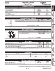
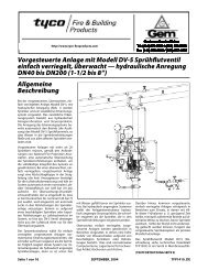
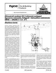
First and foremost, we are looking at the fire sprinkler protection of roof structures that are most<br />
commonly of wood joist and rafter construction (Fig. 2) or wood trusses (Fig. 3), and where there is<br />
a ceiling separating an unoccupied, combustible concealed attic space from the space below. There is<br />
also likely to be the presence of insulation above the ceiling. The ceiling slope of the attic can be from<br />
a 3:12 to 12:12 pitch. The attic space may be at temperatures at or above 40F at all times, for which a<br />
wet pipe sprinkler system may be used, or the attic space may be periodically or at all times be at temperatures<br />
below 40F, for which a dry pipe sprinkler system must be used. The temperature in the attic<br />
spaces at all times must not exceed 150F.<br />
NOTE: The design criteria with respect to piping materials and hydraulic demand will vary greatly between<br />
the uses of a wet pipe system versus a dry pipe system. A wet pipe system will provide in most cases the option<br />
for using CPVC pipe and fittings within the attic space, as well as provide hydraulic advantages through<br />
smaller hydraulic design areas. Temperatures in the attic space will govern the need for when a wet pipe system<br />
may be used or when a dry pipe system must be used.<br />
There are generally four steps to applying the “Specific Application <strong>Sprinklers</strong> for Protecting <strong>Attic</strong>s”.<br />
1. Determine if Model BB (Back to Back), SD (Single Directional), HIP, or AP (<strong>Attic</strong> Plus) <strong>Sprinklers</strong><br />
are needed. If more than one type of roof construction is present, select the correct sprinkler for<br />
each area.<br />
2. Check the roof pitch for the areas to be protected and then refer to TFP610, Table A to confirm<br />
applicability of the selected sprinkler. A roof pitch of between 4:12 to 12:12 can be protected by<br />
the 5.6K & 8.0K Model BB, Model SD, and Model HIP <strong>Sprinklers</strong>. A roof pitch of 3:12 to 12:12<br />
can be protected by the 4.2K Model BB and Model AP <strong>Sprinklers</strong>. If more than one slope is being<br />
used on a project, select the correct sprinkler for each area.<br />
3. Follow the design criteria provided in TFP610 for each type sprinkler, for example, sprinkler positioning,<br />
coverage area, distance below roof deck, and distance from obstructions to water distribution.<br />
The use of Specific Application <strong>Sprinklers</strong> will differ from installation criteria found in<br />
NFPA. Therefore, it is extremely important to refer to TFP610.<br />
4. Hydraulically calculate the sprinkler system in accordance with TFP610 making certain that the<br />
correct criteria is used for either a wet pipe or dry pipe system.<br />
Other considerations will include where CPVC piping materials may be used instead of steel piping<br />
materials. In some cases, consideration will also need to be given for adding insulation for CPVC pipe<br />
materials.<br />
RAFTER<br />
JOIST<br />
TRUSS<br />
Figure 2<br />
Figure 3<br />
<br />
The Use of Specific Application <strong>Sprinklers</strong><br />
for Protecting <strong>Attic</strong>s
To determine whether to use the Model BB, SD, HIP, or AP, the designer must study the roof shapes<br />
and determine which of the following roof types apply:<br />
- gable up to 60 feet wide (Example 1)<br />
- gable greater than 60 feet up to 80 feet wide (Example 2)<br />
- hip roof framed with joist and rafters (Example 3)<br />
- hip roof framed with trusses (Example 4)<br />
- gable roof with double shear walls (Example 5)<br />
- gable roof with a single shear wall (Example 6)<br />
- main roof area connected (i.e., non-compartmented) to gable ends (Example 7)<br />
- main roof area with built-on (i.e., compartmented) dormers (Example 8)<br />
- reduced size attic over occupied attic space (Example 9)<br />
NOTE: Some applications will use a combination of the examples presented. Shear walls shown in Examples<br />
5 and 6 may be under a hip roof instead of a gable roof, or the built-on dormers in Example 8 may be of a<br />
variety of shapes other than shown.<br />
Some applications may have roof lines that are “cut up” to the point of being too complex for applying<br />
“Specific Application <strong>Sprinklers</strong> for Protecting <strong>Attic</strong>s”, or be outside the scope of application for the Model<br />
BB, SD, HIP, and AP <strong>Sprinklers</strong>. In these cases, the designer will have to use Standard Spray <strong>Sprinklers</strong>.<br />
Examples 1 through 9 provide comparisons for locating Standard Spray <strong>Sprinklers</strong> and “Specific<br />
Application <strong>Sprinklers</strong> for Protecting <strong>Attic</strong>s”. Appendix B provides information for the spacing of<br />
Standard Spray <strong>Sprinklers</strong>. In general the maximum 8 foot on center spacing was used in the examples<br />
on the assumption that most designers would prefer the minimum design pressure of 7 psi as<br />
compared to 20 psi as referenced in the 2007 edition of NFPA 13, Table 8.2.2.1(a) so as to avoid<br />
larger system water flow demands and larger pipe sizes.<br />
Each example is presented in four pages:<br />
- An overview.<br />
- Comparative sprinkler layouts. For the purposes of the examples and with regard to laying out<br />
Standard Spray <strong>Sprinklers</strong>, an assumption has been made that the maximum spacing perpendicular<br />
to the slope will be 8 feet so as to minimize the design pressure to 7 psi. Whereas, if the designer<br />
wanted to increase the spacing over 8 feet, the minimum design pressure would be 20 psi.<br />
- Wet pipe system hydraulic design comparisons. For the purposes of the examples and with<br />
regard to wet system hydraulic demand, an assumption has been made that either the Model AP<br />
<strong>Sprinklers</strong> or Standard Spray <strong>Sprinklers</strong> will have a K-factor of 4.2 so as to minimize the design<br />
flow.<br />
- Dry pipe system hydraulic design comparisons. For the purposes of the examples and with<br />
regard to dry system hydraulic demand, an assumption has been made that either the Model AP<br />
<strong>Sprinklers</strong> or Standard Spray <strong>Sprinklers</strong> will have a K-factor of 5.6 so as to avoid the use of galvanized<br />
pipe. The designer could also use 4.2 K-factor sprinklers and gain a hydraulic advantage if<br />
galvanized pipe were to be utilized.<br />
Examples 4 and 7 specifically provide comparisons to illustrate the hydraulic advantage for those<br />
areas utilizing more than four Model AP (<strong>Attic</strong> Plus) <strong>Sprinklers</strong>. Please note and with reference to<br />
Appendix A, TFP610, Figure 20: “For individual areas requiring more than four AP <strong>Sprinklers</strong>,<br />
the maximum area of attic protected by AP <strong>Sprinklers</strong> is limited to 3000 ft 2 (279 m 2 ) in any single<br />
area. Areas must be separated by a minimum of 15 feet (4,6 m) by an area protected by BB,<br />
SD, or HIP <strong>Sprinklers</strong>, in order to be considered separate areas.”<br />
The Use of Specific Application <strong>Sprinklers</strong><br />
for Protecting <strong>Attic</strong>s
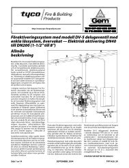
EXAMPLE 1<br />
(Figures 4A thru 4F):<br />
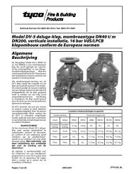
For Example 1, we determine that the roof type is a gable with a roof span of 60 feet and a ceiling slope<br />
of 8:12. Figure 4A illustrates the Standard Spray Sprinkler layout. In terms of “Specific Application<br />
<strong>Sprinklers</strong> for Protecting <strong>Attic</strong>s” shown in Figure 4B, this roof type is best protected with Model BB<br />
<strong>Sprinklers</strong>. The Model BB Specific Application <strong>Attic</strong> Sprinkler throws a narrow but long pattern.<br />
The narrow spacing along the ridge serves two purposes. The response time is reduced by placing the<br />
sprinklers no farther than 6 feet apart, and the spray can be concentrated in the throw direction to<br />
obtain a pattern that will cover up to 30 feet in each direction when measured horizontally. There are<br />
three different models (i.e., BB1, BB2 & BB3) that account for different roof slopes, and each model<br />
is available in three different orifice sizes (K=4.2, 5.6, or 8.0). With reference to Appendix A, TFP610,<br />
Table A, we would select the Model BB2 based on ceiling pitch of 8:12, and for a roof span of 60 feet,<br />
we could use either the K=5.6 or 8.0.<br />
Figures 4A and 4B clearly demonstrate the reduction from 5 branch lines (Fig. 4A) to 1 branch line<br />
(Fig. 4B) when using Model BB <strong>Sprinklers</strong> instead of Standard Spray <strong>Sprinklers</strong>. In addition to the<br />
reduction in branch lines, we also clearly see a reduction of 115 sprinklers to 30 sprinklers. Obviously<br />
buildings of varying widths and pitched ceilings would have an overall affect on branch line and<br />
sprinkler reduction. Nonetheless, we would expect a significant reduction in branch lines, sprinklers,<br />
material costs, and labor costs through the use of the Model BB Back to Back <strong>Sprinklers</strong>.<br />
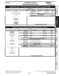
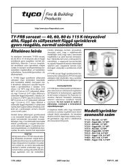
Wet Pipe System Calculations:<br />
Fig. 4C – Standard <strong>Sprinklers</strong>: 177.6 GPM<br />
Fig. 4D – <strong>Attic</strong> <strong>Sprinklers</strong>: 190.0 GPM<br />
Dry Pipe System Calculations:<br />
Fig. 4E – Standard <strong>Sprinklers</strong>: 414.4 GPM<br />
Fig. 4F – <strong>Attic</strong> <strong>Sprinklers</strong>: 266.0 GPM<br />
<br />
The Use of Specific Application <strong>Sprinklers</strong><br />
for Protecting <strong>Attic</strong>s
36'<br />
12<br />
8<br />
EXAMPLE 1:<br />
SPRINKLER LAYOUTS<br />
60'<br />
180'<br />
FIG. 4A<br />
115 STANDARD SPRAY SPRINKLERS<br />
20'<br />
REQUIRED<br />
SPRINKLERS<br />
AT RIDGE<br />
36'<br />
14'-5"<br />
14'-5"<br />
7'-2"<br />
FIVE<br />
BRANCHLINES<br />
2'<br />
8' MAX. TO MINIMIZE DESIGN PRESSURE TO 7 PSI<br />
2'<br />
FIG. 4B<br />
30 MODEL BB2 SPRINKLERS<br />
6' MAX.<br />
ONE<br />
BRANCHLINE<br />
AT RIDGE<br />
The Use of Specific Application <strong>Sprinklers</strong><br />
for Protecting <strong>Attic</strong>s
36'<br />
12<br />
8<br />
EXAMPLE 1:<br />
WET PIPE SYSTEM CALCULATIONS<br />
60'<br />
180'<br />
FIG. 4C<br />
1464 FT 2 (16 SPRINKLERS K = 4.2)<br />
MIN. DESIGN AREA:<br />
1500 FT 2 x 0.75 (a) x 1.3 (b)<br />
= 1463 FT 2<br />
115 STANDARD SPRAY SPRINKLERS<br />
16 SPRINKLERS x 11.1 GPM (c)<br />
= 177.6 GPM (d)<br />
FIG. 4D<br />
REF. TFP610, FIG. 20-A-1<br />
30 MODEL BB2 SPRINKLERS<br />
5 MODEL BB2 SPRINKLERS<br />
AT 38 GPM = 190.0 GPM (d)<br />
NOTES:<br />
(a) 25% REDUCTION FOR QR<br />
SPRINKLERS AND 20 FOOT<br />
CEILING.<br />
(b) 30% INCREASE FOR SLOPED<br />
CEILING.<br />
(c) 8' x 12' x 0.1 GPM/FT 2 = 9.6 GPM;<br />
HOWEVER, 11.1 GPM IS MINIMUM<br />
FLOW AT 7 PSI.<br />
(d) ACTUAL DEMAND WILL BE<br />
HIGHER DUE TO BALANCING.<br />
<br />
The Use of Specific Application <strong>Sprinklers</strong><br />
for Protecting <strong>Attic</strong>s
36'<br />
12<br />
8<br />
EXAMPLE 1:<br />
DRY PIPE SYSTEM CALCULATIONS<br />
60'<br />
180'<br />
FIG. 4E<br />
2592 FT 2 (28 SPRINKLERS K = 5.6)<br />
MIN. DESIGN AREA:<br />
1500 FT 2 x 1.3 (a) x 1.3 (b)<br />
= 2535 FT 2<br />
115 STANDARD SPRAY SPRINKLERS<br />
28 SPRINKLERS x 14.8 GPM (c)<br />
= 414.4 GPM (d)<br />
(NO QR REDUCTION FOR<br />
DRY PIPE SYSTEMS)<br />
FIG. 4F<br />
REF. TFP610, FIG. 20-A-1<br />
30 MODEL BB2 SPRINKLERS<br />
7 MODEL BB2 SPRINKLERS<br />
AT 38 GPM = 266.0 GPM (d)<br />
NOTES:<br />
(a) 30% INCREASE FOR DRY<br />
SYSTEM.<br />
(b) 30% INCREASE FOR SLOPED<br />
CEILING.<br />
(c) 8' x 12' x 0.1 GPM/FT 2 = 9.6 GPM;<br />
HOWEVER, 14.8 GPM IS MINIMUM<br />
FLOW AT 7 PSI.<br />
(d) ACTUAL DEMAND WILL BE<br />
HIGHER DUE TO BALANCING.<br />
The Use of Specific Application <strong>Sprinklers</strong><br />
for Protecting <strong>Attic</strong>s
EXAMPLE 2<br />
(Figures 5A thru 5F):<br />
For Example 2, we determine that the roof type is a gable with a roof span of 80 feet and a ceiling<br />
slope of 8:12. Figure 5A illustrates the Standard Spray Sprinkler layout. In terms of “Specific<br />
Application <strong>Sprinklers</strong> for Protecting <strong>Attic</strong>s” shown in Figures 5B, this roof type is best protected<br />
with Model BB <strong>Sprinklers</strong>, plus two rows of Model AP <strong>Sprinklers</strong> to cover the 10 foot roof span areas<br />
at the eaves. With reference to Appendix A, TFP610, Table A, we would select the Model BB2 based<br />
on ceiling pitch of 8:12, and we could use either the K=5.6 or 8.0. based on allowable roof span.<br />
With reference to Appendix A, TFP610, Figure 14A, “For single ridge construction, AP <strong>Sprinklers</strong><br />
can be used to protect up to 10 feet of width at the eaves beyond the maximum allowable 60 foot, 40<br />
foot, or 20 foot spans of the BB <strong>Sprinklers</strong>”.<br />
NOTES:<br />
• Where SD <strong>Sprinklers</strong> are used (ref. Appendix A, TFP610, Figure 14B), AP <strong>Sprinklers</strong> can be used to protect<br />
up to 10 feet of width at the eaves beyond the maximum allowable 40 foot, 30 foot, or 10 foot spans<br />
of the SD <strong>Sprinklers</strong>.<br />
• Where HIP <strong>Sprinklers</strong> are used for hip roof construction (ref. Appendix A, TFP610, Figure 15), BB<br />
<strong>Sprinklers</strong> can be used in the center portion and HIP <strong>Sprinklers</strong> down the entire hip. AP <strong>Sprinklers</strong> can<br />
then be used to protect the eaves beyond the BB <strong>Sprinklers</strong> as described above, and AP <strong>Sprinklers</strong> can be<br />
used to protect up to 10 feet of width beyond the maximum allowable 28 foot or 20 foot horizontal coverage<br />
of the HIP <strong>Sprinklers</strong>.<br />
• The use of <strong>Attic</strong> <strong>Sprinklers</strong> CANNOT be considered for attics over 80 feet wide.<br />
Figure 5B illustrates how the Model BB <strong>Sprinklers</strong> can be used in combination with the 2 additional<br />
rows of Model AP <strong>Sprinklers</strong> to protect attic spans up to 80 feet. There is the obvious advantage of<br />
using the Model BB <strong>Sprinklers</strong> as compared to the use of only Standard Spray <strong>Sprinklers</strong>. There will<br />
also be increased benefits for the use of Model AP <strong>Sprinklers</strong>, as explained later under the sub-section<br />
“When Can CPVC Pipe and Fittings Be Used”.<br />
Wet Pipe System Calculations:<br />
Fig. 5C – Standard <strong>Sprinklers</strong>: 255.3 GPM<br />
Fig. 5D - <strong>Attic</strong> <strong>Sprinklers</strong> with AP <strong>Sprinklers</strong> at Eaves: 212.2 GPM<br />
Dry Pipe System Calculations:<br />
Fig. 5E – Standard <strong>Sprinklers</strong>: 429.2 GPM<br />
Fig. 5F - <strong>Attic</strong> <strong>Sprinklers</strong> with AP <strong>Sprinklers</strong> at Eaves: 295.6 GPM<br />
10<br />
The Use of Specific Application <strong>Sprinklers</strong><br />
for Protecting <strong>Attic</strong>s
48'<br />
12<br />
8<br />
EXAMPLE 2:<br />
SPRINKLER LAYOUTS<br />
80'<br />
180'<br />
FIG. 5A<br />
161 STANDARD SPRAY SPRINKLERS<br />
REQUIRED<br />
SPRINKLERS<br />
AT RIDGE<br />
26'-8"<br />
13'-9" 48'<br />
13'-9"<br />
13'-9"<br />
6'-9"<br />
SEVEN<br />
BRANCHLINES<br />
2'<br />
8' MAX. TO MINIMIZE DESIGN PRESSURE TO 7 PSI<br />
2'<br />
FIG. 5B<br />
10'<br />
30 MODEL BB2 SPRINKLERS<br />
PLUS 36 MODEL AP SPRINKLERS<br />
6' MAX.<br />
60' COVERAGE THREE<br />
BRANCHLINES<br />
10' MAX.<br />
10'<br />
The Use of Specific Application <strong>Sprinklers</strong><br />
for Protecting <strong>Attic</strong>s<br />
11
48'<br />
12<br />
8<br />
EXAMPLE 2:<br />
WET PIPE SYSTEM CALCULATIONS<br />
80' 180'<br />
FIG. 5C<br />
1994 FT 2 (23 SPRINKLERS K = 4.2)<br />
MIN. DESIGN AREA:<br />
1500 FT 2 x 1.3 (a) = 1950 FT 2<br />
161 STANDARD SPRAY SPRINKLERS<br />
23 SPRINKLERS x 11.1 GPM (b)<br />
= 255.3 GPM (c)<br />
(NO QR REDUCTION FOR<br />
26'-8" CEILING HEIGHT)<br />
FIG. 5D<br />
REF. TFP610, FIG. 20-B-2<br />
30 MODEL BB2 SPRINKLERS<br />
PLUS 36 MODEL AP SPRINKLERS<br />
5 MODEL BB2 SPRINKLERS<br />
AT 38 GPM PLUS 2 MODEL AP<br />
SPRINKLERS AT 11.1 GPM<br />
= 212.2 GPM (c)<br />
NOTES:<br />
(a) 30% INCREASE FOR SLOPED<br />
CEILING.<br />
(b) 8' x 11.5' x 0.1 GPM/FT 2 = 9.2 GPM;<br />
HOWEVER, 11.1 GPM IS MINIMUM<br />
FLOW AT 7 PSI.<br />
(c) ACTUAL DEMAND WILL BE<br />
HIGHER DUE TO BALANCING.<br />
12<br />
The Use of Specific Application <strong>Sprinklers</strong><br />
for Protecting <strong>Attic</strong>s
48'<br />
12<br />
8<br />
EXAMPLE 2:<br />
DRY PIPE SYSTEM CALCULATIONS<br />
80' 180'<br />
FIG. 5E<br />
2564 FT 2 (29 SPRINKLERS K = 5.6)<br />
MIN. DESIGN AREA:<br />
1500 FT 2 x 1.3 (a) x 1.3 (b)<br />
= 2535 FT 2<br />
161 STANDARD SPRAY SPRINKLERS<br />
29 SPRINKLERS x 14.8 GPM (c)<br />
= 429.2 GPM (d)<br />
(NO QR REDUCTION FOR<br />
DRY PIPE SYSTEMS)<br />
FIG. 5F<br />
REF. TFP610, FIG. 20-B-2<br />
30 MODEL BB2 SPRINKLERS<br />
PLUS 36 MODEL AP SPRINKLERS<br />
7 MODEL BB2 SPRINKLERS<br />
AT 38 GPM PLUS 2 MODEL AP<br />
SPRINKLERS AT 14.8 GPM<br />
= 295.6 GPM (d)<br />
NOTES:<br />
(a) 30% INCREASE FOR DRY<br />
SYSTEM.<br />
(b) 30% INCREASE FOR SLOPED<br />
CEILING.<br />
(c) 8' x 11.5' x 0.1 GPM/FT 2 = 9.2 GPM;<br />
HOWEVER, 14.8 GPM IS MINIMUM<br />
FLOW AT 7 PSI.<br />
(d) ACTUAL DEMAND WILL BE<br />
HIGHER DUE TO BALANCING.<br />
The Use of Specific Application <strong>Sprinklers</strong><br />
for Protecting <strong>Attic</strong>s<br />
13
EXAMPLE 3<br />
(Figures 6A thru 6F):<br />
For Example 3, we determine that the roof type is a hip with a roof span of 40 feet. We also determine<br />
that the framing for the roof structure is rafters framed perpendicular to the outside walls with a<br />
ceiling pitch of 12:12. Figure 6A illustrates the Standard Spray Sprinkler layout. In terms of “Specific<br />
Application <strong>Sprinklers</strong> for Protecting <strong>Attic</strong>s” shown in Figure 6B, this roof type is best protected with<br />
a combination of Model BB and HIP <strong>Sprinklers</strong>.<br />
The hip roof framed with rafters and joists presents a unique challenge for which the previously<br />
described Model BB <strong>Sprinklers</strong> cannot exclusively be used. The Model HIP Specific Application <strong>Attic</strong><br />
Sprinkler covers the area of the hip in the attic. This is a slightly different concept than the BB (Back<br />
to Back). The HIP Sprinkler is located along the slope running down the hip, and throws a 90° pattern<br />
toward the outside eaves. This pattern allows the water to “corner” and control the fire. The HIP<br />
does not discharge much water directly up or down the hip, but rather it discharges most of the pattern<br />
out to each side (90°) down the slope of the roof. This sprinkler is spaced 6 feet to 3 feet on center<br />
down the slope. To use the HIP Sprinkler, the framing must be perpendicular to the outside wall and<br />
the maximum throw cannot exceed 28 feet measured horizontally.<br />
Layout of the HIP takes special consideration. From the intersection of the top of the hip and the<br />
ridge, the maximum distance down the slope of the hip is 3 feet. Start the layout with the first sprinkler<br />
as close to that point as possible, but no further, while staying 6 inches away from the face of the<br />
trusses. Remember the slope of the hip is not equal to the slope of the roof from the ridge to the outside<br />
wall. In the case of the example, the hip length is 34'-6". Continue to space sprinklers down the<br />
hip at a maximum of 6 feet on center as measured along the slope of the hip. From the intersection<br />
of the bottom of the hip and the wall, the maximum distance up the slope of the hip is based on the<br />
sprinkler being within 7'-6" from the outside wall as measured flat (plan view). The distance between<br />
the top and bottom locations based on 6 foot maximum on center spacing determines that four additional<br />
HIP’s will be necessary for a total of 6 HIP’s per hip ridge.<br />
Once again, we see evidence of the significant reduction in branch lines and sprinklers.<br />
Wet Pipe System Calculations:<br />
Fig. 6C – Standard <strong>Sprinklers</strong>: 299.7 GPM<br />
Fig. 6D – <strong>Attic</strong> <strong>Sprinklers</strong>: 125.0 GPM<br />
Dry Pipe System Calculations:<br />
Fig. 6E – Standard <strong>Sprinklers</strong>: 651.2 GPM<br />
Fig. 6F – <strong>Attic</strong> <strong>Sprinklers</strong>: 225.0 GPM<br />
14<br />
The Use of Specific Application <strong>Sprinklers</strong><br />
for Protecting <strong>Attic</strong>s
12<br />
12<br />
40'<br />
100'<br />
EXAMPLE 3:<br />
SPRINKLER LAYOUTS<br />
RAFTERS FRAMED PERPENDICULAR<br />
TO OUTSIDE WALL<br />
FIG. 6A<br />
A<br />
70 STANDARD SPRAY SPRINKLERS<br />
REQUIRED<br />
SPRINKLERS<br />
AT RIDGE<br />
20'<br />
28'-4"<br />
11'-3"<br />
11'-3"<br />
5'-8"<br />
A<br />
8' MAX. TO MINIMIZE<br />
DESIGN PRESSURE<br />
TO 7 PSI<br />
SECTION A-A<br />
FIG. 6B<br />
10 MODEL BB3<br />
SPRINKLERS PLUS 24<br />
MODEL HIP SPRINKLERS<br />
DIRECTION<br />
OF VIEW B<br />
20'<br />
10'-7"<br />
UPPER HIP<br />
LOCATION<br />
3'-0"<br />
MAX.<br />
*<br />
18'-9" REQUIRES<br />
FOUR ADDITIONAL<br />
HIP SPRINKLERS<br />
18'-9"* RESULTING IN A<br />
34'-6" TOTAL OF SIX HIP<br />
SPRINKLERS<br />
6' MAX.<br />
20'<br />
20' 60'<br />
20'<br />
20'<br />
7'-6"<br />
LOWER HIP<br />
LOCATION<br />
12'-11"<br />
MAX.<br />
VIEW B<br />
The Use of Specific Application <strong>Sprinklers</strong><br />
for Protecting <strong>Attic</strong>s<br />
15
12<br />
12<br />
40'<br />
100'<br />
EXAMPLE 3:<br />
WET PIPE SYSTEM CALCULATIONS<br />
RAFTERS FRAMED PERPENDICULAR<br />
TO OUTSIDE WALL<br />
FIG. 6C<br />
1488 FT 2 (27 SPRINKLERS K = 4.2)<br />
1500 FT 2 x 0.75 (a) x 1.3 (b)<br />
MIN. DESIGN AREA:<br />
= 1463 FT 2<br />
70 STANDARD SPRAY SPRINKLERS<br />
27 SPRINKLERS x 11.1 GPM (c)<br />
= 299.7 GPM (d)<br />
FIG. 6D<br />
10 MODEL BB3<br />
SPRINKLERS PLUS 24<br />
MODEL HIP SPRINKLERS<br />
REF. TFP610, FIG. 20-A-2<br />
5 MODEL BB3 SPRINKLERS AT<br />
25 GPM = 125.0 GPM (d)<br />
NOTES:<br />
(a) 25% REDUCTION FOR QR<br />
SPRINKLERS AND 20 FOOT<br />
CEILING.<br />
(b) 30% INCREASE FOR SLOPED<br />
CEILING.<br />
(c) 8' x 8' x 0.1 GPM/FT 2 = 6.4 GPM;<br />
HOWEVER, 11.1 GPM IS MINIMUM<br />
FLOW AT 7 PSI.<br />
(d) ACTUAL DEMAND WILL BE<br />
HIGHER DUE TO BALANCING.<br />
16<br />
The Use of Specific Application <strong>Sprinklers</strong><br />
for Protecting <strong>Attic</strong>s
12<br />
12<br />
40'<br />
100'<br />
EXAMPLE 3:<br />
DRY PIPE SYSTEM CALCULATIONS<br />
RAFTERS FRAMED PERPENDICULAR<br />
TO OUTSIDE WALL<br />
FIG. 6E<br />
2576 FT 2 (44 SPRINKLERS K = 5.6)<br />
MIN. DESIGN AREA:<br />
1500 FT 2 x 1.3 (a) x 1.3 (b)<br />
= 2535 FT 2<br />
70 STANDARD SPRAY SPRINKLERS<br />
44 SPRINKLERS x 14.8 GPM (c)<br />
= 651.2 GPM (d)<br />
(NO QR REDUCTION FOR<br />
DRY PIPE SYSTEMS)<br />
FIG. 6F<br />
10 MODEL BB3<br />
SPRINKLERS PLUS 24<br />
MODEL HIP SPRINKLERS<br />
REF. TFP610, FIG. 20-A-2<br />
7 MODEL BB3 SPRINKLERS AT<br />
25 GPM PLUS 2 MODEL HIP<br />
SPRINKLERS AT 25 GPM<br />
= 225.0 GPM (d)<br />
NOTE: PER TFP610, FIG. 20-A-2<br />
THERE IS ALSO A SECOND<br />
CALCULATION FOR THE MOST<br />
DEMANDING SEVEN SPRINKLERS<br />
THAT HAS NOT BEEN SHOWN.<br />
NOTES:<br />
(a) 30% INCREASE FOR DRY<br />
SYSTEM.<br />
(b) 30% INCREASE FOR SLOPED<br />
CEILING.<br />
(c) 8' x 8' x 0.1 GPM/FT 2 = 6.4 GPM;<br />
HOWEVER, 14.8 GPM IS MINIMUM<br />
FLOW AT 7 PSI.<br />
(d) ACTUAL DEMAND WILL BE<br />
HIGHER DUE TO BALANCING.<br />
The Use of Specific Application <strong>Sprinklers</strong><br />
for Protecting <strong>Attic</strong>s<br />
17
EXAMPLE 4<br />
(Figures 7A thru 7J):<br />
For Example 4, we determine that the roof type is a hip with a roof span of 40 feet. We also determine<br />
that the framing for the roof structure is trusses framed parallel to the outside walls with a ceiling<br />
pitch of 12:12. Figure 7A illustrates the Standard Spray Sprinkler layout. In terms of “Specific<br />
Application <strong>Sprinklers</strong> for Protecting <strong>Attic</strong>s” shown in Figures 7B and 7C, this roof type is best protected<br />
with a combination of either Model BB <strong>Sprinklers</strong> and Standard Spray <strong>Sprinklers</strong> (Fig. 7B) or<br />
Model BB <strong>Sprinklers</strong> and Model AP <strong>Sprinklers</strong> (Fig. 7C).<br />
The use of trusses in the hip area and where the trusses are parallel to the outside wall precludes the<br />
use of the Model HIP <strong>Sprinklers</strong> shown in Example 3. Therefore, the use of either Standard Spray<br />
<strong>Sprinklers</strong> or Model AP <strong>Sprinklers</strong> must be considered within the hip areas. There is not a significant<br />
reduction in sprinklers with installing AP <strong>Sprinklers</strong> instead of Standard Spray <strong>Sprinklers</strong> in combination<br />
with the Model BB <strong>Sprinklers</strong>; however, there will be increased benefits for the use of Model<br />
AP <strong>Sprinklers</strong>, as explained later under the sub-section “When Can CPVC Pipe and Fittings Be<br />
Used”, as well as hydraulic advantages.<br />
Wet Pipe System Calculations:<br />
Fig. 7D – Standard <strong>Sprinklers</strong>: 299.7 GPM<br />
Fig. 7E – <strong>Attic</strong> <strong>Sprinklers</strong> with Standard <strong>Sprinklers</strong> at Hips:<br />
the more demanding* of 147.2 GPM or 285.9 GPM (see footnote below)<br />
Fig. 7F – <strong>Attic</strong> <strong>Sprinklers</strong> with Model AP <strong>Sprinklers</strong> at Hips:<br />
the more demanding* of 147.2 GPM or 199.8 GPM (see footnote below)<br />
Dry Pipe System Calculations:<br />
Fig. 7G – Standard <strong>Sprinklers</strong>: 651.2 GPM<br />
Fig. 7H – <strong>Attic</strong> <strong>Sprinklers</strong> with Standard <strong>Sprinklers</strong> at Hips:<br />
the more demanding* of 204.6 GPM or 481.2 GPM (see footnote below)<br />
Fig. 7J – <strong>Attic</strong> <strong>Sprinklers</strong> with Model AP <strong>Sprinklers</strong> at Hips:<br />
the more demanding* of 204.6 GPM or 266.4 GPM (see footnote below)<br />
* Flow is not always indicative of the most demanding.<br />
Required system pressure must also be taken into consideration.<br />
18<br />
The Use of Specific Application <strong>Sprinklers</strong><br />
for Protecting <strong>Attic</strong>s
12<br />
12<br />
40'<br />
100'<br />
EXAMPLE 4:<br />
SPRINKLER LAYOUTS<br />
TRUSSES FRAMED PARALLEL<br />
TO OUTSIDE WALL<br />
FIG. 7A<br />
A<br />
70 STANDARD SPRAY SPRINKLERS<br />
REQUIRED<br />
SPRINKLERS<br />
AT RIDGE<br />
20'<br />
28'-4"<br />
11'-3"<br />
11'-3"<br />
5'-8"<br />
A<br />
8' MAX. TO MINIMIZE<br />
DESIGN PRESSURE<br />
TO 7 PSI<br />
SECTION A-A<br />
FIG. 7B<br />
10 MODEL BB3<br />
SPRINKLERS PLUS 38<br />
STD. SPRAY SPRINKLERS<br />
6' MAX.<br />
FIG. 7C<br />
10 MODEL BB3<br />
SPRINKLERS PLUS 36<br />
MODEL AP SPRINKLERS<br />
6' MAX.<br />
20' 60'<br />
20'<br />
The Use of Specific Application <strong>Sprinklers</strong><br />
for Protecting <strong>Attic</strong>s<br />
19
12<br />
12<br />
40'<br />
100'<br />
EXAMPLE 4:<br />
WET PIPE SYSTEM CALCULATIONS<br />
TRUSSES FRAMED PARALLEL<br />
TO OUTSIDE WALL<br />
FIG. 7D<br />
1488 FT 2 (27 SPRINKLERS K = 4.2)<br />
MIN. DESIGN AREA:<br />
1500 FT 2 x 0.75 (a) x 1.3 (b)<br />
= 1463 FT 2<br />
70 STANDARD SPRAY SPRINKLERS<br />
27 SPRINKLERS x 11.1 GPM (c)<br />
= 299.7 GPM (d)<br />
FIG. 7E - CALCULATION 1 FIG. 7E - CALCULATION 2<br />
10 MODEL BB3<br />
SPRINKLERS PLUS 38<br />
STD. SPRAY SPRINKLERS<br />
10 MODEL BB3<br />
SPRINKLERS PLUS 38<br />
STD. SPRAY SPRINKLERS<br />
REF. TFP610, FIG. 20-C-3<br />
5 MODEL BB3 SPRINKLERS AT 25 GPM PLUS 2 STD.<br />
SPRAY SPRINKLERS AT 11.1 GPM = 147.2 GPM (d)<br />
1520 FT 2 TO INCLUDE ENTIRE COVERAGE AREA<br />
OF LAST MODEL BB3 SPRINKLER<br />
REF. TFP610, FIG. 20-C-3<br />
MIN. DESIGN AREA:<br />
1500 FT 2 x 0.75 (a) x 1.3 (b) = 1463 FT 2<br />
3 MODEL BB3 SPRINKLERS AT 25 GPM PLUS 19 STD.<br />
SPRAY SPRINKLERS AT 11.1 GPM = 285.9 GPM(d)<br />
FIG. 7F - CALCULATION 1 FIG. 7F - CALCULATION 2<br />
10 MODEL BB3<br />
SPRINKLERS PLUS 36<br />
MODEL AP SPRINKLERS<br />
10 MODEL BB3<br />
SPRINKLERS PLUS 36<br />
MODEL AP SPRINKLERS<br />
REF. TFP610, FIG. 20-B-3<br />
5 MODEL BB3 SPRINKLERS AT 25 GPM PLUS 2<br />
MODEL AP SPRINKLERS AT 11.1 GPM = 147.2 GPM (d)<br />
800 FT 2 (CALCULATE ALL AP SPRINKLERS UP TO<br />
A MAXIMUM OF 1500 FT 2 )<br />
REF. TFP610, FIG. 20-B-3<br />
18 MODEL AP SPRINKLERS AT 11.1 GPM<br />
= 199.8 GPM (d)<br />
NOTES:<br />
(a) 25% REDUCTION FOR QR<br />
SPRINKLERS AND 20 FOOT<br />
CEILING.<br />
(b) 30% INCREASE FOR SLOPED<br />
CEILING.<br />
(c) 8' x 8' x 0.1 GPM/FT 2 = 6.4 GPM;<br />
HOWEVER, 11.1 GPM IS MINIMUM<br />
FLOW AT 7 PSI.<br />
(d) ACTUAL DEMAND WILL BE<br />
HIGHER DUE TO BALANCING.<br />
20<br />
The Use of Specific Application <strong>Sprinklers</strong><br />
for Protecting <strong>Attic</strong>s
12<br />
12<br />
40'<br />
100'<br />
EXAMPLE 4:<br />
DRY PIPE SYSTEM CALCULATIONS<br />
TRUSSES FRAMED PARALLEL<br />
TO OUTSIDE WALL<br />
FIG. 7G<br />
2576 FT 2 (44 SPRINKLERS K = 5.6)<br />
MIN. DESIGN AREA:<br />
1500 FT 2 x 1.3 (a) x 1.3 (b)<br />
= 2535 FT 2<br />
70 STANDARD SPRAY SPRINKLERS<br />
44 SPRINKLERS x 14.8 GPM (c)<br />
= 651.2 GPM (d)<br />
(NO QR REDUCTION FOR<br />
DRY PIPE SYSTEMS)<br />
FIG. 7H - CALCULATION 1<br />
10 MODEL BB3<br />
SPRINKLERS PLUS 38<br />
STD. SPRAY SPRINKLERS<br />
FIG. 7H - CALCULATION 2<br />
10 MODEL BB3<br />
SPRINKLERS PLUS 38<br />
STD. SPRAY SPRINKLERS<br />
REF. TFP610, FIG. 20-C-3<br />
7 MODEL BB3 SPRINKLERS AT 25 GPM PLUS 2 STD.<br />
SPRAY SPRINKLERS AT 14.8 GPM = 204.6 GPM (d)<br />
2720 FT 2 TO INCLUDE ENTIRE COVERAGE AREA<br />
OF LAST MODEL BB3 SPRINKLER<br />
REF. TFP610, FIG. 20-C-3<br />
MIN. DESIGN AREA:<br />
1500 FT 2 x 1.3 (a) x 1.3 (b) = 2535 FT 2<br />
8 MODEL BB3 SPRINKLERS AT 25 GPM PLUS 19 STD.<br />
SPRAY SPRINKLERS AT 14.8 GPM = 481.2 GPM (d)<br />
FIG. 7J - CALCULATION 1 FIG. 7J - CALCULATION 2<br />
10 MODEL BB3<br />
SPRINKLERS PLUS 36<br />
MODEL AP SPRINKLERS<br />
10 MODEL BB3<br />
SPRINKLERS PLUS 36<br />
MODEL AP SPRINKLERS<br />
REF. TFP610, FIG. 20-B-3<br />
7 MODEL BB3 SPRINKLERS AT 25 GPM PLUS 2<br />
MODEL AP SPRINKLERS AT 14.8 GPM = 204.6 GPM (d)<br />
800 FT 2 (CALCULATE ALL AP SPRINKLERS UP TO<br />
A MAXIMUM OF 1950 FT 2 )<br />
REF. TFP610, FIG. 20-B-3<br />
18 MODEL AP SPRINKLERS AT 14.8 GPM<br />
= 266.4 GPM (d)<br />
NOTES:<br />
(a) 30% INCREASE FOR DRY<br />
SYSTEM.<br />
(b) 30% INCREASE FOR SLOPED<br />
CEILING.<br />
(c) 8' x 8' x 0.1 GPM/FT 2 = 6.4 GPM;<br />
HOWEVER, 14.8 GPM IS MINIMUM<br />
FLOW AT 7 PSI.<br />
(d) ACTUAL DEMAND WILL BE<br />
HIGHER DUE TO BALANCING.<br />
The Use of Specific Application <strong>Sprinklers</strong><br />
for Protecting <strong>Attic</strong>s<br />
21
EXAMPLE 5<br />
(Figures 8A thru 8F):<br />
For Example 5, we determine that the roof is a gable having a span of 60 feet and a ceiling pitch of<br />
8:12. Figure 8A illustrates the Standard Spray Sprinkler layout. Compounding the complexity of the<br />
sprinkler design is the presence of double shear walls, where the walls are located 4 feet from the ridge<br />
on both sides of the ridge. In terms of “Specific Application <strong>Sprinklers</strong> for Protecting <strong>Attic</strong>s” shown<br />
in Figure 8B, this roof type is best protected with a combination of Model SD and Standard Spray<br />
<strong>Sprinklers</strong>.<br />
In the case of applying Standard Spray <strong>Sprinklers</strong> (Ref. Fig. 8A), this attic space arrangement presents<br />
the need for two additional rows of Standard Spray <strong>Sprinklers</strong> due to the need for locating sprinklers<br />
at the high points adjacent to the shear walls. For this type of situation, the Model SD <strong>Sprinklers</strong><br />
should be considered. The Model SD (Single Directional) Specific Application <strong>Attic</strong> Sprinkler, like<br />
the Model BB, throws a narrow but long pattern. However, unlike the Model BB, the Model SD only<br />
discharges in one direction. These sprinklers are primarily used where shear walls or draft curtains<br />
have been installed within an attic space. Three different models (i.e., SD1, SD2 & SD3) are available<br />
for different roof slopes. With reference to Appendix A, TFP610, Table A, we would select the Model<br />
SD2 based on ceiling pitch of 8:12, and we could ultimately use the minimum flow rate of 25 GPM<br />
for the 26 foot span of coverage.<br />
The corridor created by the shear walls may be protected by Standard Spray <strong>Sprinklers</strong>, as shown in<br />
Figure 8B, or Model AP <strong>Sprinklers</strong>. There would not be a significant reduction in quantity of AP<br />
<strong>Sprinklers</strong> as compared to Standard Spray <strong>Sprinklers</strong>, and the system demand would be identical.<br />
However there will be increased benefits for the use of Model AP <strong>Sprinklers</strong>, as explained later under<br />
the sub-section “When Can CPVC Pipe and Fittings Be Used”.<br />
Wet Pipe System Calculations:<br />
Fig. 8C – Standard <strong>Sprinklers</strong>: 255.3 GPM<br />
Fig. 8D – <strong>Attic</strong> <strong>Sprinklers</strong> with Standard <strong>Sprinklers</strong><br />
(or Model AP <strong>Sprinklers</strong>) between Shear Walls:<br />
the more demanding* of 125.0 GPM or 55.5 GPM (see footnote below)<br />
Dry Pipe System Calculations:<br />
Fig. 8E – Standard <strong>Sprinklers</strong>: 621.6 GPM<br />
Fig. 8F – <strong>Attic</strong> <strong>Sprinklers</strong> with Standard <strong>Sprinklers</strong><br />
(or Model AP <strong>Sprinklers</strong>) between Shear Walls:<br />
the more demanding* of 225.0 GPM or 103.6 GPM (see footnote below)<br />
* Flow is not always indicative of the most demanding.<br />
Required system pressure must also be taken into consideration.<br />
22<br />
The Use of Specific Application <strong>Sprinklers</strong><br />
for Protecting <strong>Attic</strong>s
36'<br />
12<br />
8<br />
EXAMPLE 5:<br />
SPRINKLER LAYOUTS<br />
60'<br />
180'<br />
DOUBLE SHEAR WALLS<br />
(COMPARTMENTED)<br />
FIG. 8A<br />
161 STANDARD SPRAY SPRINKLERS<br />
26'<br />
8'<br />
20'<br />
REQUIRED<br />
SPRINKLERS<br />
AT RIDGE<br />
SHEAR<br />
WALLS<br />
31'<br />
36'<br />
26'<br />
SEVEN<br />
BRANCHLINES<br />
2' 8' MAX. TO MINIMIZE DESIGN PRESSURE TO 7 PSI<br />
2'<br />
FIG. 8B<br />
60 MODEL SD2 SPRINKLERS<br />
PLUS 23 STANDARD SPRAY SPRINKLERS<br />
26'<br />
8'<br />
20'<br />
REQUIRED<br />
SPRINKLERS<br />
AT RIDGE<br />
SHEAR<br />
WALLS<br />
31'<br />
36'<br />
6' MAX.<br />
26'<br />
THREE<br />
BRANCHLINES<br />
2'<br />
8' MAX. TO MINIMIZE DESIGN PRESSURE TO 7 PSI<br />
2'<br />
The Use of Specific Application <strong>Sprinklers</strong><br />
for Protecting <strong>Attic</strong>s<br />
23
36'<br />
12<br />
8<br />
EXAMPLE 5:<br />
WET PIPE SYSTEM CALCULATIONS<br />
60'<br />
180'<br />
DOUBLE SHEAR WALLS<br />
(COMPARTMENTED)<br />
FIG. 8C<br />
1516 FT 2 (23 SPRINKLERS K = 4.2)<br />
161 STANDARD SPRAY SPRINKLERS<br />
MIN. DESIGN AREA:<br />
1500 FT 2 x 0.75 (a) x 1.3 (b)<br />
= 1463 FT 2<br />
23 SPRINKLERS x 11.1 GPM (c)<br />
= 255.3 GPM (d)<br />
FIG. 8D - CALCULATION 1<br />
60 MODEL SD2 SPRINKLERS<br />
PLUS 23 STANDARD SPRAY SPRINKLERS<br />
REF. TFP610, FIG. 20-C-1<br />
5 MODEL SD2 SPRINKLERS AT<br />
25 GPM = 125.0 GPM (d)<br />
FIG. 8D - CALCULATION 2<br />
60 MODEL SD2 SPRINKLERS<br />
PLUS 23 STANDARD SPRAY SPRINKLERS<br />
REF. TFP610, FIG. 20-C-1<br />
5 STD. SPRAY SPRINKLERS AT<br />
11.1 GPM = 55.5 GPM (d)<br />
NOTES:<br />
(a) 25% REDUCTION FOR QR<br />
SPRINKLERS AND 20 FOOT<br />
CEILING.<br />
(b) 30% INCREASE FOR SLOPED<br />
CEILING.<br />
(c) 8' x 10.25' x 0.1 GPM/FT 2 = 8.2 GPM;<br />
HOWEVER, 11.1 GPM IS MINIMUM<br />
FLOW AT 7 PSI.<br />
(d) ACTUAL DEMAND WILL BE<br />
HIGHER DUE TO BALANCING.<br />
24<br />
The Use of Specific Application <strong>Sprinklers</strong><br />
for Protecting <strong>Attic</strong>s
36'<br />
12<br />
8<br />
EXAMPLE 5:<br />
DRY PIPE SYSTEM CALCULATIONS<br />
60'<br />
180'<br />
DOUBLE SHEAR WALLS<br />
(COMPARTMENTED)<br />
FIG. 8E<br />
2597 FT 2 (42 SPRINKLERS K = 5.6)<br />
161 STANDARD SPRAY SPRINKLERS<br />
MIN. DESIGN AREA:<br />
1500 FT 2 x 1.3 (a) x 1.3 (b)<br />
= 2535 FT 2<br />
42 SPRINKLERS x 14.8 GPM (c)<br />
= 621.6 GPM (d)<br />
(NO QR REDUCTION FOR<br />
DRY PIPE SYSTEMS)<br />
FIG. 8F - CALCULATION 1<br />
60 MODEL SD2 SPRINKLERS<br />
PLUS 23 STANDARD SPRAY SPRINKLERS<br />
REF. TFP610, FIG. 20-C-1<br />
9 MODEL SD2 SPRINKLERS AT<br />
25 GPM = 225.0 GPM (d)<br />
FIG. 8F - CALCULATION 2<br />
60 MODEL SD2 SPRINKLERS<br />
PLUS 23 STANDARD SPRAY SPRINKLERS<br />
REF. TFP610, FIG. 20-C-1<br />
7 STD. SPRAY SPRINKLERS AT<br />
14.8 GPM = 103.6 GPM (d)<br />
NOTES:<br />
(a) 30% INCREASE FOR DRY<br />
SYSTEM.<br />
(b) 30% INCREASE FOR SLOPED<br />
CEILING.<br />
(c) 8' x 10.25' x 0.1 GPM/FT 2 = 8.2 GPM;<br />
HOWEVER, 14.8 GPM IS MINIMUM<br />
FLOW AT 7 PSI.<br />
(d) ACTUAL DEMAND WILL BE<br />
HIGHER DUE TO BALANCING.<br />
The Use of Specific Application <strong>Sprinklers</strong><br />
for Protecting <strong>Attic</strong>s<br />
25
EXAMPLE 6<br />
(Figures 9A thru 9F):<br />
For Example 6, we determine that the roof is a gable having a span of 60 feet and a ceiling pitch<br />
of 8:12. Compounding the complexity of the sprinkler design is the presence of a single shear wall,<br />
where the wall is located 4 feet from the ridge. Figure 9A illustrates the Standard Spray Sprinkler layout.<br />
In terms of “Specific Application <strong>Sprinklers</strong> for Protecting <strong>Attic</strong>s” shown in Figure 9B, this roof<br />
type is best protected with a combination of Model SD and Model BB <strong>Sprinklers</strong>.<br />
In the case of applying Standard Spray <strong>Sprinklers</strong>, this attic space arrangement presents the need for<br />
one additional row of Standard Spray <strong>Sprinklers</strong> due to the need for locating sprinklers at the highpoint<br />
adjacent to the shear wall.<br />
In this example with one shear wall, a corridor as shown in Example 5 is not present, and a combination<br />
of Model SD and Model BB <strong>Sprinklers</strong> can provide a reduction in branch lines and sprinklers.<br />
Consideration can also be given to using SD’s instead of BB’s when the ceiling pitch to maximum distance<br />
from ridge to shear wall combination permits the SD to be located 16 to 22 inches below the<br />
theoretical intersection of the shear wall and ceiling. In cases where SD’s can be used instead of BB’s,<br />
an increased hydraulic advantage can be gained. And, in the case of the wet pipe system calculations<br />
(Figs. 9C and 9D) where the <strong>Attic</strong> <strong>Sprinklers</strong> have a greater system demand than the Standard Spray<br />
<strong>Sprinklers</strong>, the use of SD’s instead of BB’s may provide the desired hydraulic advantage in addition to<br />
decreasing branch lines and sprinklers.<br />
Wet Pipe System Calculations:<br />
Fig. 9C – Standard <strong>Sprinklers</strong>: 242.2 GPM<br />
Fig. 9D – <strong>Attic</strong> <strong>Sprinklers</strong>:<br />
the greater demand* of 175.0 GPM or 190.0 GPM (see footnote below)<br />
Dry Pipe System Calculations:<br />
Fig. 9E – Standard <strong>Sprinklers</strong>: 488.4 GPM<br />
Fig. 9F – <strong>Attic</strong> <strong>Sprinklers</strong>:<br />
the greater demand* of 315.0 GPM or 266.0 GPM (see footnote below)<br />
* Flow is not always indicative of the most demanding.<br />
Required system pressure must also be taken into consideration.<br />
26<br />
The Use of Specific Application <strong>Sprinklers</strong><br />
for Protecting <strong>Attic</strong>s
36'<br />
12<br />
8<br />
EXAMPLE 6:<br />
SPRINKLER LAYOUTS<br />
60'<br />
180'<br />
SINGLE SHEAR WALL<br />
(COMPARTMENTED)<br />
FIG. 9A<br />
138 STANDARD SPRAY SPRINKLERS<br />
26'<br />
20'<br />
REQUIRED<br />
SPRINKLERS<br />
AT RIDGE<br />
SHEAR<br />
WALL<br />
31'<br />
36'<br />
34'<br />
SIX<br />
BRANCHLINES<br />
2'<br />
8' MAX. TO MINIMIZE DESIGN PRESSURE TO 7 PSI<br />
2'<br />
FIG. 9B<br />
30 MODEL SD2 SPRINKLERS<br />
PLUS 30 MODEL BB2 SPRINKLERS<br />
*<br />
26'<br />
20'<br />
REQUIRED<br />
SPRINKLERS<br />
AT RIDGE<br />
SHEAR<br />
WALL<br />
31'<br />
36'<br />
6' MAX.<br />
*<br />
MODEL BB SPRINKLERS MAY BE<br />
SUBSTITUTED BY MODEL SD SPRINKLERS<br />
IF STRUCTURE AND SPRINKLER LOCATION<br />
MEET CRITERIA DESCRIBED BELOW<br />
34'<br />
TWO<br />
BRANCHLINES<br />
X<br />
MODEL BB<br />
SPRINKLER<br />
AT RIDGE<br />
NOT USED<br />
12<br />
EQUAL<br />
SLOPE<br />
SUBSTITUTE<br />
MODEL SD<br />
SPRINKLER<br />
Y<br />
MAX.<br />
THEORETICAL 34<br />
INTERSECTION<br />
30<br />
22" MAX.<br />
16" MIN.<br />
SHEAR<br />
WALL<br />
"Y" IN INCHES<br />
26<br />
22<br />
18<br />
14<br />
4/12<br />
6/12 8/12<br />
CAN NOT<br />
SUBSTITUTE<br />
4" TO 6" ROOF SLOPE<br />
10/12 12/12<br />
The Use of Specific Application <strong>Sprinklers</strong><br />
for Protecting <strong>Attic</strong>s<br />
27
36'<br />
12<br />
8<br />
EXAMPLE 6:<br />
WET PIPE SYSTEM CALCULATIONS<br />
60'<br />
180'<br />
SINGLE SHEAR WALL<br />
(COMPARTMENTED)<br />
FIG. 9C<br />
1516 FT 2 (22 SPRINKLERS K = 4.2)<br />
138 STANDARD SPRAY SPRINKLERS<br />
MIN. DESIGN AREA:<br />
1500 FT 2 x 0.75 (a) x 1.3 (b)<br />
= 1463 FT 2<br />
22 SPRINKLERS x 11.1 GPM (c)<br />
= 244.2 GPM (d)<br />
FIG. 9D CALCULATION 1<br />
30 MODEL SD2 SPRINKLERS<br />
PLUS 30 MODEL BB2 SPRINKLERS<br />
REF. TFP610, FIG. 20-A-1 & 20-A-4<br />
5 MODEL SD2 SPRINKLERS<br />
AT 35 GPM = 175.0 GPM (d)<br />
- AND PROVE -<br />
5 MODEL BB2 SPRINKLERS<br />
AT 38 GPM = 190.0 GPM (d)<br />
CALCULATION 2<br />
NOTES:<br />
(a) 25% REDUCTION FOR QR<br />
SPRINKLERS AND 20 FOOT<br />
CEILING.<br />
(b) 30% INCREASE FOR SLOPED<br />
CEILING.<br />
(c) 8' x 12' x 0.1 GPM/FT 2 = 9.6 GPM;<br />
HOWEVER, 11.1 GPM IS MINIMUM<br />
FLOW AT 7 PSI.<br />
(d) ACTUAL DEMAND WILL BE<br />
HIGHER DUE TO BALANCING.<br />
28<br />
The Use of Specific Application <strong>Sprinklers</strong><br />
for Protecting <strong>Attic</strong>s
36'<br />
12<br />
8<br />
EXAMPLE 6:<br />
DRY PIPE SYSTEM CALCULATIONS<br />
60'<br />
180'<br />
SINGLE SHEAR WALL<br />
(COMPARTMENTED)<br />
FIG. 9E<br />
2576 FT 2 (33 SPRINKLERS K = 5.6)<br />
138 STANDARD SPRAY SPRINKLERS<br />
MIN. DESIGN AREA:<br />
1500 FT 2 x 1.3 (a) x 1.3 (b)<br />
= 2535 FT 2<br />
33 SPRINKLERS x 14.8 GPM (c)<br />
= 488.4 GPM (d)<br />
(NO QR REDUCTION FOR<br />
DRY PIPE SYSTEMS)<br />
FIG. 9F CALCULATION 1<br />
30 MODEL SD2 SPRINKLERS<br />
PLUS 30 MODEL BB2 SPRINKLERS<br />
REF. TFP610, FIG. 20-A-1 & 20-A-4<br />
9 MODEL SD2 SPRINKLERS<br />
AT 35 GPM = 315.0 GPM (d)<br />
- AND PROVE -<br />
7 MODEL BB2 SPRINKLERS<br />
AT 38 GPM = 266.0 GPM (d)<br />
CALCULATION 2<br />
NOTES:<br />
(a) 30% INCREASE FOR DRY<br />
SYSTEM.<br />
(b) 30% INCREASE FOR SLOPED<br />
CEILING.<br />
(c) 8' x 12' x 0.1 GPM/FT 2 = 9.6 GPM;<br />
HOWEVER, 14.8 GPM IS MINIMUM<br />
FLOW AT 7 PSI.<br />
(d) ACTUAL DEMAND WILL BE<br />
HIGHER DUE TO BALANCING.<br />
The Use of Specific Application <strong>Sprinklers</strong><br />
for Protecting <strong>Attic</strong>s<br />
29
EXAMPLE 7<br />
(Figures 10A thru 10J):<br />
For Example 7, we determine that there are two different roof structure configurations – a main hip<br />
roof and two smaller gable ended attic spaces. The ceiling pitch is noted to be 12:12 throughout and<br />
the gable ended attic spaces are open to the main hip roof area. Figure 10A illustrates the Standard<br />
Spray Sprinkler layout. In terms of “Specific Application <strong>Sprinklers</strong> for Protecting <strong>Attic</strong>s” shown in<br />
Figures 10B and 10C, this roof type is best protected with a combination of Model BB and Standard<br />
Spray <strong>Sprinklers</strong> (Fig. 10B) or Model BB <strong>Sprinklers</strong> and Model AP <strong>Sprinklers</strong> (Fig. 10C). With reference<br />
to Appendix A, TFP610, Table A, we would select the Model BB3 with a K-factor of 5.6 or 8.0<br />
for the main hip roof due to the 40 foot span, and we would select the BB3 with a K-factor of 4.2 for<br />
the gable ended attic spaces having the 20 foot span.<br />
The reduction in branch lines and sprinklers is once again observed with the use of Specific Application<br />
<strong>Attic</strong> <strong>Sprinklers</strong>. Further advantages of the use of AP <strong>Sprinklers</strong> as compare to Standard Spray<br />
<strong>Sprinklers</strong> are explained later under the sub-section “When Can CPVC Pipe and Fittings Be Used”.<br />
Two important elements are included in Example 7. First -- the use of the 4.2 K-factor Model BB<br />
<strong>Sprinklers</strong> with their maximum span coverage of 20 feet in the gable ended attic spaces. The smaller<br />
span rating of the 4.2 K-factor BB Sprinkler has a lower design flow than the 5.6 or 8.0 K-factor<br />
BB <strong>Sprinklers</strong>. Second– the use of Model AP <strong>Sprinklers</strong> instead of Standard Spray <strong>Sprinklers</strong> in the<br />
adjoining areas between the BB3 <strong>Sprinklers</strong>. Where areas protected by AP <strong>Sprinklers</strong> are separated by<br />
a minimum of 15 feet by areas protected by BB, SD, or HIP <strong>Sprinklers</strong>, the area protected by the AP<br />
<strong>Sprinklers</strong> can be considered a separate hydraulic design area. The potential hydraulic advantage is<br />
illustrated in Figures 10F and 10J.<br />
Wet Pipe System Calculations:<br />
Fig. 10D – Standard <strong>Sprinklers</strong>: 321.9 GPM<br />
Fig. 10E – <strong>Attic</strong> <strong>Sprinklers</strong> with Standard <strong>Sprinklers</strong> in Adjoining Areas:<br />
the more demanding* of 147.2 GPM or 304,7 GPM (see footnote below)<br />
Fig. 10F - <strong>Attic</strong> <strong>Sprinklers</strong> with Model AP <strong>Sprinklers</strong> in Adjoining Areas :<br />
the more demanding* of 147.2 GPM or 188.7 GPM (see footnote below)<br />
Dry Pipe System Calculations:<br />
Fig. 10G – Standard <strong>Sprinklers</strong>: 666.0 GPM<br />
Fig. 10H – <strong>Attic</strong> <strong>Sprinklers</strong> with Standard <strong>Sprinklers</strong> in Adjoining Areas:<br />
the more demanding* of 204.6 GPM or 467.6 GPM (see footnote below)<br />
Fig. 10J - <strong>Attic</strong> <strong>Sprinklers</strong> with Model AP <strong>Sprinklers</strong> in Adjoining Areas:<br />
the more demanding* of 204.6 GPM or 251.6 GPM (see footnote below)<br />
* Flow is not always indicative of the most demanding.<br />
Required system pressure must also be taken into consideration.<br />
30<br />
The Use of Specific Application <strong>Sprinklers</strong><br />
for Protecting <strong>Attic</strong>s
12<br />
12<br />
10'<br />
40'<br />
60'<br />
12<br />
12<br />
14'-2"<br />
28'-4"<br />
30'<br />
EXAMPLE 7:<br />
SPRINKLER LAYOUTS<br />
40'<br />
10'<br />
20'<br />
30'<br />
100'<br />
160' MAIN HIP ROOF WITH OPEN<br />
ATTIC TO GABLE ENDS<br />
FIG. 10A<br />
92 STANDARD SPRAY SPRINKLERS<br />
8' MAX. TO MINIMIZE DESIGN<br />
PRESSURE TO 7 PSI<br />
FIG. 10B<br />
24 MODEL BB3<br />
SPRINKLERS PLUS 34<br />
STD. SPRAY SPRINKLERS<br />
6' MAX.<br />
FIG. 10C<br />
24 MODEL BB3<br />
SPRINKLERS PLUS 34<br />
MODEL AP SPRINKLERS<br />
6' MAX.<br />
The Use of Specific Application <strong>Sprinklers</strong><br />
for Protecting <strong>Attic</strong>s<br />
31
12<br />
12<br />
10'<br />
40'<br />
60'<br />
12<br />
12<br />
14'-2"<br />
28'-4"<br />
30'<br />
EXAMPLE 7:<br />
WET PIPE SYSTEM CALCULATIONS<br />
40'<br />
10'<br />
FIG. 10D<br />
20'<br />
30'<br />
100'<br />
160'<br />
1512 FT 2 (29 SPRINKLERS K = 4.2)<br />
MAIN HIP ROOF WITH OPEN<br />
ATTIC TO GABLE ENDS<br />
92 STANDARD SPRAY SPRINKLERS<br />
MIN. DESIGN AREA:<br />
1500 FT 2 x 0.75 (a) x 1.3 (b) = 1463 FT 2<br />
29 SPRINKLERS x 11.1 GPM (c)<br />
= 321.9 GPM (d)<br />
FIG. 10E - CALCULATION 1<br />
24 MODEL BB3<br />
SPRINKLERS PLUS 34<br />
STD. SPRAY SPRINKLERS<br />
REF. TFP610, FIG. 20-C-5 & FIG. 20-C-3<br />
5 MODEL BB3 SPRINKLERS AT 25 GPM<br />
PLUS 2 STD. SPRAY SPRINKLERS AT<br />
11.1 GPM = 147.2 GPM (d)<br />
FIG. 10E - CALCULATION 2<br />
1640 FT 2<br />
24 MODEL BB3<br />
SPRINKLERS PLUS 34<br />
STD. SPRAY SPRINKLERS<br />
REF. TFP610, FIG. 20-C-5 & FIG. 20-C-3<br />
MIN. DESIGN AREA:<br />
1500 FT 2 x 0.75 (a) x 1.3 (b) = 1463 FT 2<br />
1 MODEL BB3 SPRINKLERS AT 25 GPM<br />
PLUS 7 MODEL BB3 SPRINKLERS AT<br />
13 GPM PLUS 17 STD. SPRAY SPRINKLERS<br />
AT 11.1 GPM = 304.7 GPM (d)<br />
FIG. 10F - CALCULATION 1<br />
24 MODEL BB3<br />
SPRINKLERS PLUS 34<br />
MODEL AP SPRINKLERS<br />
REF. TFP610, FIG. 20-B-5 & FIG. 20-B-3<br />
5 MODEL BB3 SPRINKLERS AT 25 GPM<br />
PLUS 2 MODEL AP SPRINKLERS AT<br />
11.1 GPM = 147.2 GPM (d)<br />
FIG. 10F - CALCULATION 2<br />
24 MODEL BB3<br />
SPRINKLERS PLUS 34<br />
MODEL AP SPRINKLERS<br />
REF. TFP610, FIG. 20-B-5 & FIG. 20-B-3<br />
17 MODEL AP SPRINKLERS AT 11.1 GPM<br />
= 188.7 GPM (d)<br />
700 FT 2 (CALCULATE ALL<br />
AP SPRINKLERS UP TO A<br />
MAXIMUM OF 1500 FT 2 )<br />
NOTES:<br />
(a) 25% REDUCTION FOR QR<br />
SPRINKLERS AND 20 FOOT<br />
CEILING.<br />
(b) 30% INCREASE FOR SLOPED<br />
CEILING.<br />
(c) 8' x 8' x 0.1 GPM/FT 2 = 6.4 GPM;<br />
HOWEVER, 11.1 GPM IS MINIMUM<br />
FLOW AT 7 PSI.<br />
(d) ACTUAL DEMAND WILL BE<br />
HIGHER DUE TO BALANCING.<br />
32<br />
The Use of Specific Application <strong>Sprinklers</strong><br />
for Protecting <strong>Attic</strong>s
12 12 12 14'-2"<br />
60'<br />
12<br />
28'-4"<br />
40'<br />
10' 30'<br />
EXAMPLE 7:<br />
DRY PIPE SYSTEM CALCULATIONS<br />
40'<br />
10'<br />
FIG. 10G<br />
20'<br />
30'<br />
100'<br />
2536 FT 2 (45 SPRINKLERS K = 5.6)<br />
160' MAIN HIP ROOF WITH OPEN<br />
ATTIC TO GABLE ENDS<br />
92 STANDARD SPRAY SPRINKLERS<br />
MIN. DESIGN AREA:<br />
1500 FT 2 x 1.3 (a) x 1.3 (b) = 2535 FT 2<br />
45 SPRINKLERS x 14.8 GPM (c)<br />
= 666.0 GPM (d)<br />
(NO QR REDUCTION FOR<br />
DRY PIPE SYSTEMS)<br />
FIG. 10H - CALCULATION 1<br />
24 MODEL BB3<br />
SPRINKLERS PLUS 34<br />
STD. SPRAY SPRINKLERS<br />
REF. TFP610, FIG. 20-C-5 & FIG. 20-C-3<br />
7 MODEL BB3 SPRINKLERS AT 25 GPM<br />
PLUS 2 STD. SPRAY SPRINKLERS AT<br />
14.8 GPM = 204.6 GPM (d)<br />
FIG. 10H - CALCULATION 2<br />
2600 FT 2<br />
24 MODEL BB3<br />
SPRINKLERS PLUS 34<br />
STD. SPRAY SPRINKLERS<br />
REF. TFP610, FIG. 20-C-5 & FIG. 20-C-3<br />
MIN. DESIGN AREA:<br />
1500 FT 2 x 1.3 (a) x 1.3 (b) = 2535 FT 2<br />
5 MODEL BB3 SPRINKLERS AT 25 GPM<br />
PLUS 7 MODEL BB3 SPRINKLERS AT<br />
13 GPM PLUS 17 STD. SPRAY SPRINKLERS<br />
AT 14.8 GPM = 467.6 GPM (d)<br />
FIG. 10J - CALCULATION 1<br />
24 MODEL BB3<br />
SPRINKLERS PLUS 34<br />
MODEL AP SPRINKLERS<br />
REF. TFP610, FIG. 20-B-5 & FIG. 20-B-3<br />
7 MODEL BB3 SPRINKLERS AT 25 GPM<br />
PLUS 2 MODEL AP SPRINKLERS AT<br />
14.8 GPM = 204.6 GPM (d)<br />
FIG. 10J - CALCULATION 2<br />
24 MODEL BB3<br />
SPRINKLERS PLUS 34<br />
MODEL AP SPRINKLERS<br />
REF. TFP610, FIG. 20-B-5 & FIG. 20-B-3<br />
17 MODEL AP SPRINKLERS AT 14.8 GPM<br />
= 251.6 GPM (d)<br />
700 FT 2 (CALCULATE ALL<br />
AP SPRINKLERS UP TO A<br />
MAXIMUM OF 1950 FT 2 )<br />
NOTES:<br />
(a) 30% INCREASE FOR DRY<br />
SYSTEM.<br />
(b) 30% INCREASE FOR SLOPED<br />
CEILING.<br />
(c) 8' x 8' x 0.1 GPM/FT 2 = 6.4 GPM;<br />
HOWEVER, 14.8 GPM IS MINIMUM<br />
FLOW AT 7 PSI.<br />
(d) ACTUAL DEMAND WILL BE<br />
HIGHER DUE TO BALANCING.<br />
The Use of Specific Application <strong>Sprinklers</strong><br />
for Protecting <strong>Attic</strong>s<br />
33
EXAMPLE 8:<br />
(Figures 11A thru 11F):<br />
For Example 8, we determine that the roof type is a gable with a roof span of 60 feet and a ceiling<br />
slope of 12:12. In addition, there are three built-on dormers (i.e., the dormers are built on top of<br />
the main roof sheathing creating a compartmentalization between the main roof area and the dormers).<br />
Figure 11A illustrates the Standard Spray Sprinkler layout. In terms of “Specific Application<br />
<strong>Sprinklers</strong> for Protecting <strong>Attic</strong>s” shown in Figure 11B, this roof type is best protected using Model<br />
BB <strong>Sprinklers</strong> under the main roof and Standard Spray <strong>Sprinklers</strong> within the dormers. Some dormer<br />
shapes, for example a gable roof instead of a shed roof, may lend themselves to using <strong>Attic</strong> <strong>Sprinklers</strong><br />
within the dormers.<br />
Example 8 illustrates that for Figures 11D and 11F there is no need to add any of the Standard Spray<br />
<strong>Sprinklers</strong> into the <strong>Attic</strong> Sprinkler calculation; however, per TFP610, Figure 20-C-6, each dormer<br />
area (or compartmented area having Standard Spray <strong>Sprinklers</strong>) needs to be separately calculated per<br />
NFPA 13. The largest demand would then be used for the system water supply. In this case, due to<br />
the limited number of sprinklers in each dormer, it is assumed that the <strong>Attic</strong> Sprinkler demand would<br />
automatically be the largest demand. The dormers, however, must still be individually calculated to<br />
assure proper size piping to supply the Standard Spray <strong>Sprinklers</strong>.<br />
Wet Pipe System Calculations:<br />
Fig. 11C – Standard <strong>Sprinklers</strong>: 321.9 GPM<br />
Fig. 11D – <strong>Attic</strong> <strong>Sprinklers</strong>: 190.0 GPM<br />
Dry Pipe System Calculations:<br />
Fig. 11E – Standard <strong>Sprinklers</strong>: 547.6 GPM<br />
Fig. 11F – <strong>Attic</strong> <strong>Sprinklers</strong>: 266.0 GPM<br />
34<br />
The Use of Specific Application <strong>Sprinklers</strong><br />
for Protecting <strong>Attic</strong>s
42'-4"<br />
12<br />
8 12<br />
12<br />
EXAMPLE 8:<br />
SPRINKLER LAYOUTS<br />
60'<br />
120'<br />
MAIN ROOF AREA WITH<br />
BUILT-ON DORMERS<br />
FIG. 11A<br />
123 STANDARD SPRAY SPRINKLERS<br />
(105 UNDER MAIN ROOF PLUS<br />
18 IN BUILT-ON DORMERS)<br />
8'<br />
29'<br />
10'<br />
5'<br />
REQUIRED<br />
SPRINKLERS<br />
AT RIDGE<br />
4'<br />
10'<br />
12'-1"<br />
42'-4"<br />
12'-1"<br />
12'-1"<br />
6'-1"<br />
30'<br />
8' MAX. TO MINIMIZE DESIGN<br />
PRESSURE TO 7 PSI<br />
SEVEN<br />
BRANCHLINES<br />
PLUS DORMER<br />
PROTECTION<br />
6' 12' 6'<br />
24'<br />
BUILT-ON DORMERS<br />
FIG. 11B<br />
20 MODEL BB3 SPRINKLERS<br />
UNDER MAIN ROOF PLUS<br />
18 STANDARD SPRAY SPRINKLERS<br />
IN BUILT-ON DORMERS<br />
29'<br />
10'<br />
5'<br />
10' 4' 30'<br />
6' MAX.<br />
8'<br />
ONE<br />
BRANCHLINE<br />
AT RIDGE<br />
PLUS DORMER<br />
PROTECTION<br />
6' 12' 6'<br />
24'<br />
BUILT-ON DORMERS<br />
The Use of Specific Application <strong>Sprinklers</strong><br />
for Protecting <strong>Attic</strong>s<br />
35
42'-4"<br />
12<br />
8<br />
12<br />
12<br />
EXAMPLE 8:<br />
WET PIPE SYSTEM CALCULATIONS<br />
60'<br />
120'<br />
MAIN ROOF AREA WITH<br />
BUILT-ON DORMERS<br />
FIG. 11C<br />
123 STANDARD SPRAY SPRINKLERS<br />
(105 UNDER MAIN ROOF PLUS<br />
18 IN BUILT-ON DORMERS)<br />
MIN. DESIGN AREA:<br />
1500 FT 2 x 1.3 (a) = 1950 FT 2<br />
29 SPRINKLERS x 11.1 GPM (b)<br />
= 321.9 GPM (c)<br />
(NO QR REDUCTION FOR<br />
30'-0" CEILING HEIGHT)<br />
1953 FT 2 (29 SPRINKLERS K = 4.2)<br />
BUILT-ON DORMERS<br />
FIG. 11D<br />
20 MODEL BB3 SPRINKLERS<br />
UNDER MAIN ROOF PLUS<br />
18 STANDARD SPRAY SPRINKLERS<br />
IN BUILT-ON DORMERS<br />
REF. TFP610, FIG. 20-A-1<br />
5 MODEL BB3 SPRINKLERS<br />
AT 38 GPM = 190.0 GPM (c)<br />
BUILT-ON DORMERS<br />
NOTES:<br />
(a) 30% INCREASE FOR SLOPED<br />
CEILING.<br />
(b) 8' x 8.6' x 0.1 GPM/FT 2 = 6.9 GPM;<br />
HOWEVER, 11.1 GPM IS MINIMUM<br />
FLOW AT 7 PSI.<br />
(c) ACTUAL DEMAND WILL BE<br />
HIGHER DUE TO BALANCING.<br />
36<br />
The Use of Specific Application <strong>Sprinklers</strong><br />
for Protecting <strong>Attic</strong>s
42'-4"<br />
12<br />
8<br />
12<br />
12<br />
EXAMPLE 8:<br />
DRY PIPE SYSTEM CALCULATIONS<br />
60'<br />
120'<br />
MAIN ROOF AREA WITH<br />
BUILT-ON DORMERS<br />
FIG. 11E<br />
123 STANDARD SPRAY SPRINKLERS<br />
(105 UNDER MAIN ROOF PLUS<br />
18 IN BUILT-ON DORMERS)<br />
MIN. DESIGN AREA:<br />
1500 FT 2 x 1.3 (a) x 1.3 (b) = 2535 FT 2<br />
37 SPRINKLERS x 14.8 GPM (c)<br />
= 547.6 GPM (d)<br />
(NO QR REDUCTION FOR<br />
DRY PIPE SYSTEMS)<br />
2546 FT 2 (37 SPRINKLERS K = 5.6)<br />
BUILT-ON DORMERS<br />
FIG. 11F<br />
20 MODEL BB3 SPRINKLERS<br />
UNDER MAIN ROOF PLUS<br />
18 STANDARD SPRAY SPRINKLERS<br />
IN BUILT-ON DORMERS<br />
REF. TFP610, FIG. 20-A-1<br />
7 MODEL BB3 SPRINKLERS<br />
AT 38 GPM = 266.0 GPM (d)<br />
BUILT-ON DORMERS<br />
NOTES:<br />
(a) 30% INCREASE FOR DRY<br />
SYSTEM.<br />
(b) 30% INCREASE FOR SLOPED<br />
CEILING.<br />
(c) 8' x 8.6' x 0.1 GPM/FT 2 = 6.9 GPM;<br />
HOWEVER, 14.8 GPM IS MINIMUM<br />
FLOW AT 7 PSI.<br />
(d) ACTUAL DEMAND WILL BE<br />
HIGHER DUE TO BALANCING.<br />
The Use of Specific Application <strong>Sprinklers</strong><br />
for Protecting <strong>Attic</strong>s<br />
37
EXAMPLE 9:<br />
(Figures 12A thru 12F):<br />
For Example 9, we determine that the roof type is a gable with a roof span of 20 feet and a ceiling<br />
slope of 12:12. The attic space is over occupied space within the pitched roof creating a smaller attic<br />
space than the 40 foot width the building might otherwise have. Figure 12A illustrates the Standard<br />
Spray Sprinkler layout. In terms of “Specific Application <strong>Sprinklers</strong> for Protecting <strong>Attic</strong>s” shown in<br />
Figure 12B, this roof type is best protected using Model BB <strong>Sprinklers</strong>.<br />
With reference to Appendix A, TFP610, Table A, we would select the Model BB3 based on ceiling<br />
pitch of 12:12, and for a roof span of 20 feet, we would use the K=4.2. The smaller span rating (up to<br />
20 feet) for the 4.2 K-factor BB Sprinkler provides a much lower design flow than the 5.6 or 8.0 K-<br />
factor BB <strong>Sprinklers</strong>, and certainly a much lower design flow than Standard Spray <strong>Sprinklers</strong>.<br />
Wet Pipe System Calculations:<br />
Fig. 11C – Standard <strong>Sprinklers</strong>: 255.3 GPM<br />
Fig. 11D – <strong>Attic</strong> <strong>Sprinklers</strong>: 65.0 GPM<br />
Dry Pipe System Calculations:<br />
Fig. 11E – Standard <strong>Sprinklers</strong>: 666.0 GPM<br />
Fig. 11F – <strong>Attic</strong> <strong>Sprinklers</strong>: 91.0 GPM<br />
38<br />
The Use of Specific Application <strong>Sprinklers</strong><br />
for Protecting <strong>Attic</strong>s
14'-2"<br />
12<br />
12<br />
20'<br />
120'<br />
ATTIC SPACE OVER<br />
OCCUPIED SPACE WITHIN<br />
PITCHED ROOF<br />
EXAMPLE 9:<br />
SPRINKLER LAYOUTS<br />
FIG. 12A<br />
45 STANDARD SPRAY SPRINKLERS<br />
REQUIRED<br />
SPRINKLERS<br />
AT RIDGE<br />
9'-2"<br />
14'-2"<br />
5'<br />
20'<br />
FIG. 12B<br />
20 MODEL BB3 4.2 K SPRINKLERS<br />
10'<br />
20'<br />
10'<br />
8' MAX. TO MINIMIZE DESIGN<br />
PRESSURE TO 7 PSI<br />
THREE<br />
BRANCHLINES<br />
6' MAX.<br />
ONE<br />
BRANCHLINE<br />
AT RIDGE<br />
The Use of Specific Application <strong>Sprinklers</strong><br />
for Protecting <strong>Attic</strong>s<br />
39
14'-2"<br />
12<br />
12<br />
20'<br />
120'<br />
ATTIC SPACE OVER<br />
OCCUPIED SPACE WITHIN<br />
PITCHED ROOF<br />
EXAMPLE 9:<br />
WET PIPE SYSTEM CALCULATIONS<br />
FIG. 12C<br />
1224 FT 2 (23 SPRINKLERS K = 4.2)<br />
45 STANDARD SPRAY SPRINKLERS<br />
MIN. DESIGN AREA:<br />
1500 FT 2 x 0.6 (a) x 1.3 (b) = 1170 FT 2<br />
23 SPRINKLERS x 11.1 GPM (c)<br />
= 255.3 GPM (d)<br />
FIG. 12D<br />
20 MODEL BB3 4.2 K SPRINKLERS<br />
REF. TFP610, FIG. 20-A-1<br />
5 MODEL BB3 SPRINKLERS<br />
AT 13 GPM = 65.0 GPM (d)<br />
NOTES:<br />
(a) 40% REDUCTION FOR QR<br />
SPRINKLERS AND 10 FOOT<br />
CEILING.<br />
(b) 30% INCREASE FOR SLOPED<br />
CEILING.<br />
(c) 8' x 6.8' x 0.1 GPM/FT 2 = 5.4 GPM;<br />
HOWEVER, 11.1 GPM IS MINIMUM<br />
FLOW AT 7 PSI.<br />
(d) ACTUAL DEMAND WILL BE<br />
HIGHER DUE TO BALANCING.<br />
40<br />
The Use of Specific Application <strong>Sprinklers</strong><br />
for Protecting <strong>Attic</strong>s
14'-2"<br />
12<br />
12<br />
20'<br />
120'<br />
ATTIC SPACE OVER<br />
OCCUPIED SPACE WITHIN<br />
PITCHED ROOF<br />
EXAMPLE 9:<br />
DRY PIPE SYSTEM CALCULATIONS<br />
FIG. 12E<br />
2400 FT 2 (45 SPRINKLERS K = 5.6)<br />
45 STANDARD SPRAY SPRINKLERS<br />
MIN. DESIGN AREA:<br />
1500 FT2 x 1.3 (a) x 1.3 (b)<br />
= 2535 FT 2<br />
45 SPRINKLERS x 14.8 GPM (c)<br />
= 666.0 GPM (d)<br />
(NO QR REDUCTION FOR<br />
DRY PIPE SYSTEMS)<br />
FIG. 12F<br />
20 MODEL BB3 4.2 K SPRINKLERS<br />
REF. TFP610, FIG. 20-A-1<br />
7 MODEL BB3 SPRINKLERS<br />
AT 13 GPM = 91.0 GPM (d)<br />
NOTES:<br />
(a) 30% INCREASE FOR DRY<br />
SYSTEM.<br />
(b) 30% INCREASE FOR SLOPED<br />
CEILING.<br />
(c) 8' x 6.8' x 0.1 GPM/FT 2 = 5.4 GPM;<br />
HOWEVER, 14.8 GPM IS MINIMUM<br />
FLOW AT 7 PSI.<br />
(d) ACTUAL DEMAND WILL BE<br />
HIGHER DUE TO BALANCING.<br />
The Use of Specific Application <strong>Sprinklers</strong><br />
for Protecting <strong>Attic</strong>s<br />
41
WET PIPE VERSUS DRY PIPE SPRINKLER SYSTEMS<br />
When considering the use of either a wet pipe sprinkler system or a dry pipe sprinkler system there are<br />
four basic criteria to consider:<br />
• ambient temperature<br />
• piping materials<br />
• hydraulic design<br />
• water delivery times (dry pipe sprinkler systems)<br />
Ambient Temperature<br />
Where attic spaces are at temperatures at or above 40F at all times, a wet pipe sprinkler system may<br />
be used. Where attic spaces may be periodically or at all times at temperatures below 40F, a dry pipe<br />
sprinkler system must be used.<br />
NOTE: Instead of a dry pipe sprinkler system, consideration could be given to the use of an anti-freeze solution<br />
filled wet pipe sprinkler system. For the purposes of this application guideline, references to wet pipe<br />
sprinkler systems is only for water filled systems.<br />
Piping Materials<br />
The following piping materials may be used as a function of system type.<br />
Piping Material Wet Pipe Dry Pipe<br />
Black Steel A A<br />
Galvanized Steel A A<br />
CPVC A* N/A<br />
A: Applicable NA: Not Applicable<br />
* refer to “When Can CPVC Pipe and Fittings Be Used” sub-section<br />
Hydraulic Design<br />
As can be seen in the Application Examples there will be increased areas of hydraulic design or<br />
increased number of sprinklers to be hydraulically designed for a dry pipe sprinkler system. The use<br />
of a dry pipe system may present a challenge to meeting water supply demands. The use of “Specific<br />
Application Sprinkler for Protecting <strong>Attic</strong>s” can significantly reduce the water supply demand – especially<br />
for dry pipe sprinkler systems.<br />
Water Delivery Times (Dry Pipe Sprinkler Systems)<br />
Due to the reduction of branch lines and corresponding system volume attributed to the use of<br />
“Specific Application <strong>Sprinklers</strong> for Protecting <strong>Attic</strong>s”, the need for a dry pipe valve quick opening<br />
device or the need to prove water delivery time may be eliminated.<br />
42<br />
The Use of Specific Application <strong>Sprinklers</strong><br />
for Protecting <strong>Attic</strong>s
There is an inherent delay in getting water to the sprinklers in a dry pipe sprinkler system. Although<br />
there are many variables that affect water delivery times (James Golinveaux, “Variables That Affect<br />
the Performance of Dry Pipe Systems” September 2002), NFPA 13 only makes reference to system<br />
volume as the controlling factor.<br />
When using Standard Spray <strong>Sprinklers</strong> for light hazard occupancies, and installing per the requirements<br />
of NFPA 13, system volumes up to 500 gallons are assumed to deliver water in sufficient time.<br />
System volumes greater of 500 gallons and up to 750 gallons are assumed to deliver water in sufficient<br />
time when a dry pipe valve quick opening device is installed, or as an alternative, the quick opening<br />
device may be omitted if a water delivery time of 60 seconds is proven. For system volumes of 750 gallons<br />
or greater, a water delivery of up to 60 seconds must be proven. If a system designer can limit the<br />
volume to less than 500 gallons, a quick opening device need not be installed and water delivery time<br />
need not be proven. If the system designer can limit volume to less than 750 gallons and the system<br />
designer specifies the use of a dry pipe valve quick opening device, the water delivery time need not<br />
be proven.<br />
For 5.6K & 8.0K Model BB <strong>Sprinklers</strong>, Model HIP <strong>Sprinklers</strong>, and Model SD <strong>Sprinklers</strong>, the requirements<br />
provided in NFPA 13 for Standard Spray <strong>Sprinklers</strong> in light hazard applications apply. When<br />
using “Specific Application <strong>Attic</strong> <strong>Sprinklers</strong> for Protecting <strong>Attic</strong>s” in dry pipe sprinkler systems, there<br />
is an additional consideration for the use of 4.2K, Model BB <strong>Sprinklers</strong> or Model AP <strong>Sprinklers</strong>. For<br />
any system volume (Ref. Appendix A, TFP610 Table A), the water delivery time for the 4.2K Model<br />
BB <strong>Sprinklers</strong> must not exceed 45 seconds and for the Model AP <strong>Sprinklers</strong> water delivery time must<br />
not exceed 60 seconds.<br />
In all cases, however, limiting system volume for dry pipe sprinkler systems through the use of<br />
“Specific Application <strong>Sprinklers</strong> for Protecting <strong>Attic</strong>s” should be beneficial with respect to the potential<br />
for eliminating dry pipe valve quick opening devices and/or the potential for eliminating the need<br />
for proving water delivery times.<br />
The Use of Specific Application <strong>Sprinklers</strong><br />
for Protecting <strong>Attic</strong>s<br />
43
WHEN CAN CPVC PIPE AND FITTINGS BE USED<br />
The use of CPVC Pipe and Fittings to supply sprinklers at the ceiling below combustible concealed<br />
attic space, where the attic space required sprinklers, had been prohibited. The use of CPVC Pipe and<br />
Fittings within an attic space to supply sprinklers in the attic space, had also been prohibited.<br />
Ironically, installing CPVC within attic spaces is considered extremely desirable from an installer’s<br />
standpoint. Pre-fabrication of steel pipe for sloped ceiling applications is difficult. When combined<br />
with small, barely accessible areas, the installation of steel pipe using pipe wrenches is further complicated.<br />
CPVC that is light weight, field cut in place, and solvent cemented provides the ideal piping<br />
material.<br />
The use of “Specific Application <strong>Sprinklers</strong> For <strong>Attic</strong> Spaces” provides an alternative for the use<br />
of CPVC, assuming that the systems are wet pipe. With reference to Appendix A, TFP610,<br />
TFPB BlazeMaster® CPVC piping may be used in a combustible concealed attic spaces requiring<br />
sprinklers when installed in accordance with Installation Handbook IH1900 and the following<br />
guidelines.<br />
NOTE: Where the use of non-combustible insulation is specified, verify with the insulation manufacturer<br />
as to the non-combustibility of the insulation. The non-combustible insulation (e.g., fiberglass) may be faced<br />
or unfaced. Where faced, the facing need not be non-combustible. The insulation is to have a flame spread<br />
index of not more than 25. Verify chemical compatibility of the insulation with BlazeMaster CPVC by<br />
consulting www.lubrizol.com.<br />
TFBP BlazeMaster CPVC may be used to supply the wet system ceiling sprinklers on the floor below.<br />
There must be 6 inches of non-combustible insulation covering the pipe extending 12 inches on each<br />
side away from the centerline of the pipe, and the area above the CPVC must be protected by Model<br />
BB, SD, HIP, or AP <strong>Sprinklers</strong> (Ref. Fig. 13A). If the pipe is located inside the ceiling joist, the joist<br />
channel must be covered or filled with 6 inches of non-combustible insulation on top of the pipe and<br />
the area above must be protected by BB, SD, HIP, or AP <strong>Sprinklers</strong> (Ref. Fig. 13B). Insulation is for<br />
fire protection purposes. It is not freeze protection. BlazeMaster CPVC must be installed in accordance<br />
with the BlazeMaster installation guide instructions.<br />
NOTE: Where Standard Spray <strong>Sprinklers</strong> are used in attic spaces (Figs. 4A, 5A, 5B, 6A, 7A, 7B, 8A, 8B,<br />
9A, 10A, 10B, 11A, and 12A), CPVC in accordance with it’s UL Listing cannot be used to supply the wet<br />
system ceiling sprinklers on the floor below. Where Model BB, SD, or HIP <strong>Sprinklers</strong> cannot be exclusively<br />
used, consideration should be given to using Model AP <strong>Sprinklers</strong> instead of Standard Spray <strong>Sprinklers</strong> so<br />
that the advantages of CPVC may be recognized throughout the building.<br />
With reference to Figure 14, TFBP BlazeMaster CPVC may be used exposed to supply wet system<br />
BB, SD, or HIP <strong>Sprinklers</strong> where:<br />
• Risers are vertical and protected by a BB, SD, or HIP Sprinkler located at a maximum lateral distance<br />
of 12 inches from the riser center line.<br />
• BB, SD, or HIP <strong>Sprinklers</strong> are directly mounted on the branch line.<br />
• BB, SD, or HIP <strong>Sprinklers</strong> are on armovers and located at a maximum lateral distance of 6 inches<br />
from the branch line center line.<br />
• BB, SD, or HIP <strong>Sprinklers</strong> are on vertical sprigs attached to the branch line.<br />
BlazeMaster is a registered trademark of Lubrizol Advanced Materials, Inc.<br />
44<br />
The Use of Specific Application <strong>Sprinklers</strong><br />
for Protecting <strong>Attic</strong>s
• BB, SD, or HIP <strong>Sprinklers</strong> are on armover or angled sprigs, and located at a maximum lateral<br />
distance of 6 inches from the branch line centerline.<br />
• A minimum lateral distance of 18 inches is maintained between the CPVC pipe and a heat producing<br />
device such as heat pumps, fan motors, and heat lamps.<br />
TFBP BlazeMaster CPVC may be used exposed to provide wet system, vertical or angled, sprigs to<br />
AP <strong>Sprinklers</strong> (Ref. Figs. 15A and 15B) where:<br />
• The exposed portion of an angled sprig is a maximum length of 3 feet, the sprig is supported<br />
within 12 inches of the AP Sprinkler, and pipe hangers are provided using the CPVC hanger support<br />
for horizontal pipe runs.<br />
• Vertical sprigs have a maximum exposed length of 10 feet, the AP Sprinkler is located at a maximum<br />
lateral distance of 12 inches from the sprig centerline, and the sprig is supported at the<br />
swing joint to the AP Sprinkler.<br />
• A minimum 6 inches deep of non-combustible insulation extends 12 inches on each side away<br />
from the centerline of the CPVC branch line feeding the AP sprigs (Ref. Fig. 15A). If the CPVC<br />
branch line is located inside the ceiling joist, the joist channel must be covered or filled with a<br />
minimum of 6 inches deep of non-combustible insulation on top of the branch line supplying<br />
the AP sprigs (Ref. Fig. 15B). Insulation is for fire protection purposes. It is not freeze protection.<br />
Additional depth of non-combustible insulation may be added to reduce the exposed length of<br />
the AP sprigs.<br />
• A minimum lateral distance of 18 inches is maintained between the CPVC pipe and a heat producing<br />
device such as heat pumps, fan motors, and heat lamps.<br />
ATTIC<br />
SPRINKLER<br />
PROTECTED<br />
SPACE<br />
12" MIN.<br />
(304,8 mm)<br />
12" MIN.<br />
(304,8 mm)<br />
6" MIN.<br />
(152,4 mm)<br />
NON-COMBUSTIBLE INSULATION<br />
FOR FIRE PROTECTION OF CPVC PIPE,<br />
NOT FREEZE PROTECTION<br />
OPTION A<br />
OPTION B<br />
ATTIC<br />
SPRINKLER<br />
PROTECTED<br />
SPACE<br />
JOIST<br />
CEILING<br />
CPVC PIPE<br />
& FITTINGS<br />
CEILING<br />
SPRINKLER<br />
NON-COMBUSTIBLE<br />
INSULATION FOR FIRE<br />
PROTECTION OF CPVC<br />
PIPE, NOT FREEZE<br />
PROTECTION<br />
CPVC PIPE<br />
& FITTINGS<br />
CEILING<br />
SPRINKLER<br />
6" MIN.<br />
(152,4 mm)<br />
JOIST<br />
CEILING<br />
Figures 13A & 13B<br />
The Use of Specific Application <strong>Sprinklers</strong><br />
for Protecting <strong>Attic</strong>s<br />
45
A<br />
A<br />
A = 6" (150 mm) MAX.<br />
B = 12" (300 mm) MAX.<br />
B<br />
A<br />
ANGLE SPRIG<br />
ARMOVER SPRIG<br />
BRANCHLINE<br />
VERTICAL SPRIG<br />
B<br />
DIRECT MOUNT<br />
ARMOVER<br />
BRANCHLINE<br />
VERTICAL RISER<br />
VERTICAL RISER<br />
EXPOSED CPVC WITH BB, SD, AND HIP SPRINKLERS<br />
Figure 14<br />
EXPOSED CPVC<br />
WITH AP SPRINKLERS<br />
AND<br />
BRANCHLINE OVER JOISTS<br />
3'-0" MAX.<br />
(0,9 m)<br />
JOIST<br />
AP<br />
SPRINKLER<br />
AP<br />
SPRIG<br />
6" MIN.<br />
(152,4 mm)<br />
10'-0" MAX.<br />
(3,0 m)<br />
JOIST<br />
AP<br />
SPRINKLER<br />
AP<br />
SPRIG<br />
6" MIN.<br />
(152,4 mm)<br />
12" MIN.<br />
(304,8 mm)<br />
12" MIN.<br />
(304,8 mm)<br />
12" MIN.<br />
(304,8 mm)<br />
12" MIN.<br />
(304,8 mm)<br />
NON-COMBUSTIBLE<br />
INSULATION FOR FIRE<br />
PROTECTION OF CPVC<br />
PIPE, NOT FREEZE<br />
PROTECTION<br />
CEILING<br />
NON-COMBUSTIBLE<br />
INSULATION FOR FIRE<br />
PROTECTION OF CPVC<br />
PIPE, NOT FREEZE<br />
PROTECTION<br />
CEILING<br />
OPTION A<br />
OPTION B<br />
EXPOSED CPVC WITH AP<br />
SPRINKLERS<br />
AND BRANCHLINE WTHIN<br />
JOISTS<br />
3'-0" MAX.<br />
(0,9 m)<br />
AP<br />
SPRINKLER<br />
AP<br />
SPRIG<br />
10'-0" MAX.<br />
(3,0 m)<br />
AP<br />
SPRINKLER<br />
AP<br />
SPRIG<br />
JOIST<br />
JOIST<br />
6" MIN. NON-COMBUSTIBLE<br />
(152,4 mm) INSULATION FOR FIRE<br />
PROTECTION OF CPVC<br />
PIPE, NOT FREEZE<br />
CEILING PROTECTION<br />
OPTION A<br />
6" MIN.<br />
(152,4 mm)<br />
CEILING<br />
NON-COMBUSTIBLE<br />
INSULATION FOR FIRE<br />
PROTECTION OF CPVC<br />
PIPE, NOT FREEZE<br />
PROTECTION<br />
OPTION B<br />
Figures 15A & 15B<br />
46<br />
The Use of Specific Application <strong>Sprinklers</strong><br />
for Protecting <strong>Attic</strong>s
BETTER FIRE PROTECTION<br />
Originally, a research program was established to expand the UL Listing of CPVC. In particular,<br />
the research program was intended to investigate the use of CPVC to supply sprinklers at the ceiling<br />
below a combustible concealed attic space, where the attic space required sprinklers. The initial<br />
plan was to have standard response Standard Spray <strong>Sprinklers</strong> (which were located in accordance with<br />
NFPA 13 installation requirements) operate and control the fire, and then evaluate the damage to the<br />
CPVC. In the test program, the fire (started between the sprinklers) burned up the slope, setting the<br />
entire underside of the roof on fire. It burned through the roof in several different locations.<br />
The results of the test are reported in “Investigation of Specific Application <strong>Sprinklers</strong> Installed in<br />
Sloped Combustible <strong>Attic</strong> Spaces” Underwriters Laboratories Inc. Project 94NK9620, EX683, for<br />
Central Sprinkler Co., Issued: August 23, 1994. The test was a failure, not because the CPVC failed,<br />
but because the sprinklers failed to provide sufficient protection as evidenced by the “Roof Deck <strong>Fire</strong><br />
Penetration Area” and “<strong>Fire</strong> Involvement Area” (Tables 1 and 2).<br />
The development of the Specific Application <strong>Attic</strong> <strong>Sprinklers</strong> (Model BB, HIP, and SD), at that time,<br />
was the result of the failure of Standard Spray <strong>Sprinklers</strong> to provide sufficient protection in a situation<br />
that was well within the allowable protection schemes described in NFPA 13.<br />
In full scale testing, the Specific Application <strong>Attic</strong> <strong>Sprinklers</strong> demonstrated that they could effectively<br />
protect an attic configuration as evidenced by the minimized “Roof Deck <strong>Fire</strong> Penetration Area” and<br />
“<strong>Fire</strong> Involvement Area” (Tables 3 and 4). They demonstrated this by comparative fire testing proving<br />
their superiority to Standard Spray <strong>Sprinklers</strong> in these applications by having a spray pattern that<br />
could effectively wet the floors and walls of these attic spaces even with the challenging construction<br />
features and obstructions frequently found within these areas. Also they are positioned in such a manner<br />
that the thermal sensitivity of the sprinkler is optimized. In addition they effectively meet the<br />
challenges presented by the slope of these ceiling configurations by having a design requirement that<br />
is significantly better than traditionally required by NFPA.<br />
Since this testing in the early 1990’s, there have been significant changes to the installation requirements<br />
provided in NFPA 13 for sloped ceiling combustible concealed attic spaces. While increasing<br />
the effectiveness of Standard Spray <strong>Sprinklers</strong>, the 2002 and 2007 editions of NFPA 13 have severely<br />
restricted the use of Standard Spray <strong>Sprinklers</strong>, making the use of “Specific Application <strong>Sprinklers</strong> for<br />
Protecting <strong>Attic</strong>s” even more advantageous. However, better fire protection can still be expected from<br />
the <strong>Attic</strong> <strong>Sprinklers</strong> due to sprinkler location and development of spray pattern.<br />
Sprinkler Location<br />
The Model BB, SD, and HIP <strong>Sprinklers</strong> are located at the high points of the attic spaces where their<br />
positioning for heat response is optimized. This heat responsive optimization combined with the long<br />
throw water distribution (Ref. Fig. 1) are expected to outperform rows of Standard Spray <strong>Sprinklers</strong><br />
that will tend to have sprinkler operations at high points even when the fire is under sprinklers at low<br />
points.<br />
Development Of Spray Pattern<br />
The unique spray patterns of the Model BB, SD, and HIP <strong>Sprinklers</strong> (Ref. Fig. 1) are better shaped<br />
for the roof slope of attic spaces and can be expected to “fill-in” spaces that cannot be assumed to be<br />
“filled-in” with the semi-hemispherical spray patterns of Standard Spray <strong>Sprinklers</strong>. The flat spray pattern<br />
of the Model AP <strong>Sprinklers</strong> (Ref. Fig. 1) can be expected to be advantageous when compared to<br />
Standard Spray <strong>Sprinklers</strong> when it becomes necessary to supplement the coverage areas of the Models<br />
BB, SD, and HIP <strong>Sprinklers</strong>.<br />
The Use of Specific Application <strong>Sprinklers</strong><br />
for Protecting <strong>Attic</strong>s<br />
47
Table 1<br />
<strong>Fire</strong> Test Results, Model A SSU, 4/12 (in. / in.) Roof Pitch<br />
Damage<br />
Assessment<br />
(Approximate Area)<br />
Test<br />
Number<br />
Illustration<br />
Number<br />
Number of<br />
<strong>Sprinklers</strong><br />
operated<br />
Sprinkler<br />
Operation,<br />
ID # - Time<br />
Mins:secs.<br />
Roof Deck <strong>Fire</strong><br />
Penetration<br />
area/sq. ft. †<br />
<strong>Fire</strong><br />
Involvement<br />
area/sq. ft. ‡<br />
8 B15, B16 2<br />
9-1:34<br />
10-1:49<br />
0 16<br />
9 B17, B18 2<br />
10 B19, B20, B21 13<br />
9-2:46<br />
10- 2:26<br />
11-6:09<br />
17-6:14<br />
*<br />
64 122<br />
68 480<br />
* 11 <strong>Sprinklers</strong> operated between 6:14 and 7:10<br />
† Portion of roof totally consumed by fire resulting in the specified opening area<br />
‡ Portion of roof exhibiting any signs of charring<br />
Table 2<br />
<strong>Fire</strong> Test Results, Model A SSU, 8/12 (in. / in.) Roof Pitch<br />
Damage<br />
Assessment<br />
(Approximate Area)<br />
Test<br />
Number<br />
Illustration<br />
Number<br />
Number of<br />
<strong>Sprinklers</strong><br />
operated<br />
Sprinkler<br />
Operation,<br />
ID # - Time<br />
Mins:secs.<br />
Roof Deck <strong>Fire</strong><br />
Penetration<br />
area/sq. ft. †<br />
<strong>Fire</strong><br />
Involvement<br />
area/sq. ft. ‡<br />
17 B35, B36,<br />
B37, B38<br />
10<br />
6- 20:43<br />
7- 20:43<br />
9- 5:28<br />
10- 4:19<br />
11- 5:32<br />
12- 21:43<br />
13- 20:53<br />
14- 22:28<br />
15- 20:48<br />
17- 21:08<br />
31 400<br />
18 B39, B40 2<br />
19 B41, B42 3<br />
9-1:43<br />
11- 1:59<br />
10-31:39<br />
14-0:56<br />
20- 1:51<br />
0 6<br />
8 52<br />
† Portion of roof totally consumed by fire resulting in the specified opening area<br />
‡ Portion of roof exhibiting any signs of charring<br />
48<br />
The Use of Specific Application <strong>Sprinklers</strong><br />
for Protecting <strong>Attic</strong>s
Table 3<br />
<strong>Fire</strong> Test Results, Model BB1 – 17/32,<br />
4/12 (in. / in.) Roof Pitch<br />
Damage<br />
Assessment<br />
(Approximate Area)<br />
Test<br />
Number<br />
Illustration<br />
Number<br />
Number of<br />
<strong>Sprinklers</strong><br />
operated<br />
Sprinkler<br />
Operation,<br />
ID # - Time<br />
Mins:secs.<br />
Roof Deck <strong>Fire</strong><br />
Penetration<br />
area/sq. ft. †<br />
<strong>Fire</strong><br />
Involvement<br />
area/sq. ft. ‡<br />
1 B1, B2 5 9 - 5:28<br />
10 - 4:19<br />
11 - 5:32<br />
12 - 21:43<br />
13 - 20:53<br />
0 16<br />
2 B3, B4 2<br />
3 B5, B6 4<br />
13 - 8:27<br />
14 - 11:39<br />
8 - 0:42<br />
9 - 0:28<br />
10 - 0:45<br />
11 - 1:36<br />
0 45<br />
0 0<br />
4 B7, B6 1 13 - 7:18 0 40<br />
5 B9, B10 5<br />
6 B11, B12 2<br />
8 - 1:22<br />
9 - 1:05<br />
10 - 1:18<br />
11 - 1:33<br />
12 - 1:49<br />
10 - 1:34<br />
11 - 1:29<br />
0 32<br />
1 16<br />
7 B13, B14 1 8 - 6:33 4 33<br />
† Portion of roof totally consumed by fire resulting in the specified opening area<br />
‡ Portion of roof exhibiting any signs of charring<br />
The Use of Specific Application <strong>Sprinklers</strong><br />
for Protecting <strong>Attic</strong>s<br />
49
Table 4<br />
<strong>Fire</strong> Test Results, Model BB2 – 17/32,<br />
8/12 (in. / in.) Roof Pitch<br />
Damage<br />
Assessment<br />
(Approximate Area)<br />
Test<br />
Number<br />
Illustration<br />
Number<br />
Number of<br />
<strong>Sprinklers</strong><br />
operated<br />
Sprinkler<br />
Operation,<br />
ID # - Time<br />
Mins:secs.<br />
Roof Deck <strong>Fire</strong><br />
Penetration<br />
area/sq. ft. †<br />
<strong>Fire</strong><br />
Involvement<br />
area/sq. ft. ‡<br />
11* B22, B23 2<br />
10- 1:03<br />
11- 1:00<br />
0 0<br />
12* B25, B25, B26 1 10- 8:06 0 40<br />
13* B27, B28 2<br />
8- 1:46<br />
9- 1:36<br />
0 48<br />
14* B29, B30 1 12- 1:09 0 0<br />
15 B31, B32, 5<br />
6- 5:59<br />
7- 5:54<br />
8 - 5:26<br />
9- 5:54<br />
10- 5:49<br />
0 40<br />
16 B33, B34 7 7- 2:09<br />
8 - 1:49<br />
9- 0:55<br />
10- 1:21<br />
11- 1:27<br />
12- 2:01<br />
13- 2:03<br />
0 4<br />
† Portion of roof totally consumed by fire resulting in the specified opening area<br />
‡ Portion of roof exhibiting any signs of charring<br />
* Wet Sprinkler System was used<br />
50<br />
The Use of Specific Application <strong>Sprinklers</strong><br />
for Protecting <strong>Attic</strong>s
WHAT ARE SPECIFIC APPLICATION SPRINKLERS<br />
The 2007 edition of NFPA 13, Section 1.6.1, under New Technology states “Nothing in this standard<br />
shall be intended to restrict new technologies or alternate arrangements, provided the level of safety<br />
prescribed by this standard is not lowered.”<br />
This simple statement has allowed individuals and manufacturers to recognize the limitations of existing<br />
technology and develop truly unique products and ideas to meet the ever-changing needs of the<br />
fire protection community.<br />
Recognizing that traditional automatic sprinklers have their limitations, NFPA 13 created a special<br />
classification of sprinkler the – “Special Sprinkler” (NPFA 13, Section 3.6.2.11). Special sprinklers are<br />
intended for the protection of specific hazards or construction features and are evaluated and listed for<br />
performance under the following conditions:<br />
(1) <strong>Fire</strong> tests related to the intended hazard<br />
(2) Distribution of the spray pattern with respect to wetting of floors and walls<br />
(3) Distribution of the spray pattern with respect to obstructions<br />
(4) Evaluation of the thermal sensitivity of the sprinkler<br />
(5) Performance under horizontal or sloped ceilings<br />
(6) Area of design<br />
(7) Allowable clearance to ceilings<br />
The Use of Specific Application <strong>Sprinklers</strong><br />
for Protecting <strong>Attic</strong>s<br />
51
CONCLUSION<br />
<strong>Tyco</strong>® Peak Performance Model BB, SD, HIP, and AP “Specific Application <strong>Sprinklers</strong> for<br />
Protecting <strong>Attic</strong>s” are expected to provide a higher level of protection then Standard Spray <strong>Sprinklers</strong><br />
in combustible sloped ceiling attic spaces. These sprinklers control costs by eliminating the need for<br />
additional sprinklers and branch line piping when compared to Standard Spray <strong>Sprinklers</strong>. In many<br />
cases, an attic can be entirely protected with just one line of piping located below the peak of the roof<br />
using Model BB <strong>Sprinklers</strong>. The Models SD, HIP or AP <strong>Sprinklers</strong> can often complement the BB<br />
<strong>Sprinklers</strong> and serve to protect those areas that are particularly challenging.<br />
In many cases the “Specific Application <strong>Sprinklers</strong> for Protecting <strong>Attic</strong>s” can provide a hydraulic<br />
design advantage by lowering the system water flow demand. `Where more than four Model AP<br />
<strong>Sprinklers</strong> are utilized within an individual area, a further hydraulic design advantage (Ref. Figs. 4 &<br />
7) can be achieved as compared to the use of Standard Spray <strong>Sprinklers</strong>.<br />
The 2002 and 2007 editions of NFPA 13 have severely restricted the use of Standard Spray <strong>Sprinklers</strong><br />
making the “Specific Application <strong>Sprinklers</strong> for Protecting <strong>Attic</strong>s” even more advantageous. For<br />
example, assuming the use of Standard Spray <strong>Sprinklers</strong>, a system in a 60 foot wide attic, with up<br />
to a 12:12 roof pitch, designed to the 2007 edition of NFPA 13, would require seven branch lines to<br />
cover the main portion of the attic and several additional branch lines to cover the hip areas. With<br />
the Model BB <strong>Sprinklers</strong> combined with the Model HIP <strong>Sprinklers</strong>, the required coverage can be<br />
obtained with just one branch line running below the peak and one down each slope of the hip ridge.<br />
This piping arrangement would result in approximately 90% less pipe needed for installation. This<br />
reduction in the number of branch lines saves the cost of the pipe, fittings, hangers, and associated<br />
labor by eliminating up to five branch lines.<br />
Another important cost reduction is the use of BlazeMaster CPVC in attic spaces to feed both the<br />
Specific Application <strong>Sprinklers</strong> in a wet system, as well as the wet system sprinklers below the ceiling.<br />
Traditionally, BlazeMaster CPVC has been used on the lower floors in the joist space above a ceiling<br />
that does not require sprinklers. The cost of using CPVC on those floors can now be translated to the<br />
upper floor even if sprinklers are required in the attic.<br />
Ultimately, a design contemplated in accordance with either the 2002 or 2007 editions of NFPA 13<br />
will be much more demanding than those of previous editions. It is critical that an estimator and/<br />
or designer understand the criteria required within their jurisdiction. It is also critical to know what<br />
options exist, such as the use of “Specific Application <strong>Sprinklers</strong> for Protecting <strong>Attic</strong>s” that can gain<br />
the estimator and/or designer a competitive advantage.<br />
52<br />
The Use of Specific Application <strong>Sprinklers</strong><br />
for Protecting <strong>Attic</strong>s
ABOUT THE AUTHOR<br />
Roger S. Wilkins<br />
Director of Engineering Services<br />
Roger Wilkins is Director of Engineering Services, Research and Development for <strong>Tyco</strong> <strong>Fire</strong> &<br />
Building <strong>Products</strong> located at the Global Technology Center in Cranston, Rhode Island. During his<br />
thirty plus years of service in <strong>Tyco</strong>’s fire protection research and development department, Roger has<br />
principally been involved in product development through the preparation of technical literature –<br />
working with Engineering, Manufacturing, and Marketing. In addition, Roger has been extensively<br />
involved in offering technical support and providing product training.<br />
While employed at <strong>Tyco</strong>, he received his Associates Degree in Mechanical Engineering Technology<br />
from Roger Williams College.<br />
The Use of Specific Application <strong>Sprinklers</strong><br />
for Protecting <strong>Attic</strong>s<br />
53
54<br />
The Use of Specific Application <strong>Sprinklers</strong><br />
for Protecting <strong>Attic</strong>s
Appendix A<br />
Technical Services: Tel: (800) 381-9312 / Fax: (800) 791-5500<br />
Models BB, SD, HIP, and AP<br />
“Specific Application <strong>Sprinklers</strong><br />
for Protecting <strong>Attic</strong>s”<br />
General<br />
Description<br />
The <strong>Tyco</strong> ® Peak Performance Models<br />
BB (Back to Back), SD (Single<br />
Directional), HIP, and AP (<strong>Attic</strong><br />
Plus) “Specific Application <strong>Sprinklers</strong><br />
for Protecting <strong>Attic</strong>s” are fire sprinklers<br />
for combustible and non-combustible<br />
sloped attic spaces. The Model BB,<br />
SD, and HIP are Specific Application<br />
<strong>Attic</strong> <strong>Sprinklers</strong>, whereas the Model<br />
AP is a Specific Application Combustible<br />
Concealed Space Sprinkler having<br />
specific application criteria for its use<br />
with the Model BB, SD, and HIP in attic<br />
spaces. Specific Application <strong>Attic</strong><br />
<strong>Sprinklers</strong> provide superior fire protection<br />
in attic spaces and, when compared<br />
to Standard Spray <strong>Sprinklers</strong>,<br />
cost savings are achieved by eliminating<br />
branchline materials and the associated<br />
installation labor. “The Specific<br />
Application <strong>Sprinklers</strong> for Protecting<br />
<strong>Attic</strong>s” have undergone the most extensive<br />
fire testing ever performed for<br />
sloped attic spaces. They are UL<br />
Listed with their specific application<br />
guidelines for use as special sprinklers<br />
as defined by the NFPA.<br />
The Specific Application <strong>Attic</strong> <strong>Sprinklers</strong><br />
provide an extended coverage<br />
spacing alternative to the restricted<br />
spacing of Standard Spray <strong>Sprinklers</strong>.<br />
The restricted spacings of Standard<br />
Spray <strong>Sprinklers</strong> used within attics is<br />
described in the 2007 edition of NFPA<br />
IMPORTANT<br />
Always refer to Technical Data<br />
Sheet TFP700 for the “INSTALLER<br />
WARNING” that provides cautions<br />
with respect to handling and installation<br />
of sprinkler systems and components.<br />
Improper handling and installation<br />
can permanently damage<br />
a sprinkler system or its components<br />
and cause the sprinkler to fail<br />
to operate in a fire situation or cause<br />
it to operate prematurely.<br />
Page 1 of 28<br />
13, Table 8.6.2.2.1(a) and Section<br />
8.6.4.1.4.<br />
The Specific Application <strong>Attic</strong> <strong>Sprinklers</strong><br />
are the first sprinklers to be:<br />
• Listed for extended coverage in<br />
combustible construction.<br />
• Full-scale fire tested in both wet and<br />
dry system scenarios.<br />
• Full-scale fire tested, for use in wood<br />
truss construction.<br />
• Listed for specific roof slopes (Refer<br />
to Table A).<br />
The Specific Application <strong>Attic</strong> <strong>Sprinklers</strong><br />
provide the best level of protection<br />
and control cost by eliminating the<br />
need for additional sprinklers and<br />
branchline piping. In many cases, an<br />
attic can be entirely protected with just<br />
one line of piping located below the<br />
peak of the roof using Model BB (Back<br />
to Back) <strong>Sprinklers</strong>. If there is a need<br />
for Model SD (Single Directional) or<br />
Model HIP <strong>Sprinklers</strong>, one line of<br />
either of these sprinkler types is usually<br />
sufficient at each area being covered.<br />
For example and assuming the<br />
use of Standard Spray <strong>Sprinklers</strong>, a<br />
system in a 60 foot (18,3 m) wide attic,<br />
with up to a 12:12 roof pitch, designed<br />
to the 2007 edition of NFPA 13, would<br />
require seven branchlines to cover the<br />
main portion of the attic and several<br />
additional branchlines to cover the hip<br />
areas. With the Specific Application<br />
<strong>Attic</strong> <strong>Sprinklers</strong>, the required coverage<br />
can be obtained with just one branchline<br />
below the peak and one down<br />
each slope of the hip beam. This would<br />
result in approximately 90% less pipe<br />
needed for installation. This reduction<br />
in the number of branchlines saves the<br />
cost of the pipe, fittings, hangers, and<br />
associated labor by eliminating up to<br />
five branchlines.<br />
Another important aspect of the Specific<br />
Application <strong>Attic</strong> Sprinkler technology<br />
is the reduction in system volume.<br />
This volume reduction may result<br />
in reducing the size of a dry pipe valve<br />
(and air compressor) and possibly al-<br />
DECEMBER, 2007<br />
TFP610<br />
Appendix A<br />
TFP610<br />
55
Page 2 of 28<br />
TFP610<br />
Components:<br />
1 - Frame<br />
2 - Button<br />
3 - Sealing<br />
Assembly<br />
2-1/4"<br />
(57.2 mm)<br />
1-1/8"<br />
(28,6 mm)<br />
6<br />
4 - Bulb<br />
5 - Compression<br />
Screw<br />
6 - Deflector<br />
13/16"<br />
(20,6 mm)<br />
1-5/8"<br />
(41,3 mm)<br />
Components:<br />
1 - Body<br />
2 - Cap<br />
3 - Sealing<br />
Assembly<br />
4 - Saddle<br />
10<br />
1-9/16"<br />
(39,7 mm)<br />
11<br />
9<br />
5 - Compression 8 - Deflector<br />
Screw<br />
9 - Rivet<br />
6 - Lever<br />
10 - Diffuser<br />
7 - Deflector 11 - Link<br />
Frame<br />
Assembly<br />
2-1/4"<br />
(57,2 mm)<br />
1-1/8"<br />
(28,6 mm)<br />
FLOW<br />
1<br />
THREAD<br />
RELIEF<br />
4<br />
5<br />
FLOW<br />
FRAME<br />
ARMS<br />
2-1/8"<br />
(54,0 mm)<br />
8<br />
7<br />
6<br />
5<br />
2-1/2"<br />
(63,5 mm)<br />
FLOW<br />
FLOW<br />
FRAME<br />
ARMS<br />
3<br />
2<br />
CROSS<br />
SECTION<br />
1/2"<br />
(12,7 mm)<br />
NOMINAL<br />
MAKE-IN<br />
WRENCH<br />
FLATS<br />
3/4" NPT<br />
FRONT<br />
ELEVATION<br />
4<br />
3<br />
2 1<br />
CROSS<br />
SECTION<br />
7/16" (11,1 mm)<br />
NOMINAL MAKE-IN<br />
WRENCH<br />
HEX<br />
SIDE<br />
ELEVATION<br />
1/2"<br />
NPT<br />
FIGURE A<br />
MODEL BB1, BB2 & BB3<br />
WITH 8.0 K-FACTOR<br />
SPECIFIC APPLICATION ATTIC<br />
SPRINKLERS<br />
FIGURE B<br />
MODEL BB1, BB2 & BB3<br />
WITH 5.6 K-FACTOR<br />
SPECIFIC APPLICATION ATTIC<br />
SPRINKLERS<br />
2-1/4"<br />
(57.2 mm)<br />
1-1/8"<br />
(28,6 mm)<br />
Components:<br />
1 - Frame 4 - Bulb<br />
2 - Button 5 - Compression<br />
3 - Sealing<br />
Screw<br />
Assembly 6 - Deflector<br />
6<br />
13/16"<br />
(20,6 mm)<br />
1-5/8"<br />
(41,3 mm)<br />
8<br />
Components:<br />
1 - Body<br />
2 - Cap<br />
5 - Compression<br />
Screw<br />
8 - Deflector<br />
9 - Rivet<br />
3 - Sealing 6 - Lever<br />
10 - Link<br />
Assembly 7 - Deflector<br />
Assembly<br />
4 - Saddle<br />
Frame<br />
1-5/16"<br />
(33,3 mm)<br />
2-1/8"<br />
(54,0 mm)<br />
1-5/16"<br />
(33,4 mm)<br />
FLOW<br />
THREAD<br />
RELIEF<br />
3<br />
4<br />
5<br />
1 2<br />
CROSS<br />
SECTION<br />
FLOW<br />
FRAME<br />
ARMS<br />
2-1/8"<br />
(54,0 mm)<br />
7/16"<br />
(11,1 mm)<br />
NOMINAL<br />
MAKE-IN<br />
WRENCH<br />
FLATS<br />
1/2" NPT<br />
FRONT<br />
ELEVATION<br />
9<br />
10<br />
7<br />
6<br />
5<br />
4<br />
3<br />
2 1<br />
CROSS<br />
SECTION<br />
3"<br />
(76,2 mm)<br />
FRAME<br />
ARMS<br />
WRENCH<br />
HEX<br />
7/16"<br />
(11,1 mm)<br />
NOMINAL<br />
MAKE-IN<br />
FLOW<br />
1/2" NPT<br />
SIDE<br />
ELEVATION<br />
FIGURE C<br />
MODEL BB1, BB2 & BB3<br />
WITH 4.2 K-FACTOR<br />
SPECIFIC APPLICATION ATTIC<br />
SPRINKLERS<br />
FIGURE D<br />
MODEL SD1, SD2 & SD3<br />
WITH 5.6 K-FACTOR<br />
SPECIFIC APPLICATION ATTIC<br />
SPRINKLERS<br />
56<br />
Appendix A<br />
TFP610
TFP610 Page 3 of 28<br />
Components:<br />
2-1/8"<br />
(54,0 mm)<br />
1-1/16"<br />
(27,0 mm)<br />
1 - Frame<br />
2 - Button<br />
3 - Sealing<br />
Assembly<br />
6<br />
4 - Bulb<br />
5 - Compression<br />
Screw<br />
6 - Deflector<br />
2"<br />
(50,8 mm)<br />
1-1/4"<br />
(31,8 mm)<br />
6<br />
Components:<br />
1 - Frame<br />
2 - Sealing<br />
Assembly<br />
3 - Button<br />
4 - Bulb<br />
5 - Compression<br />
Screw<br />
6 - Deflector<br />
7 - Ejection<br />
Spring<br />
1-11/16"<br />
(42,9 mm)<br />
1<br />
THREAD<br />
RELIEF<br />
4 5<br />
2-1/8"<br />
(54,0 mm)<br />
FLOW<br />
FRAME<br />
ARMS<br />
5<br />
4<br />
3<br />
2<br />
SPRINKLER<br />
FRAME<br />
ARMS<br />
7<br />
WRENCH<br />
FLATS<br />
2-1/4"<br />
(57,2 mm)<br />
3<br />
2<br />
CROSS<br />
SECTION<br />
7/16" 1/2" NPT<br />
(11,1 mm)<br />
NOMINAL WRENCH<br />
MAKE-IN FLATS<br />
SIDE<br />
ELEVATION<br />
1<br />
CROSS<br />
SECTION<br />
1/2" NPT<br />
7/16" (11,1 mm)<br />
NOMINAL MAKE-IN<br />
FRONT<br />
ELEVATION<br />
FIGURE E<br />
MODEL HIP<br />
WITH 5.6 K-FACTOR<br />
SPECIFIC APPLICATION ATTIC<br />
SPRINKLERS<br />
FIGURE F<br />
MODEL AP<br />
WITH 4.2 or 5.6 K-FACTOR<br />
SPECIFIC APPLICATION COMBUSTIBLE<br />
CONCEALED SPACE SPRINKLERS<br />
low for quicker water delivery times,<br />
eliminating the need for an accelerator.<br />
The other cost reduction is the Listing<br />
of BlazeMaster* CPVC for use in attic<br />
spaces to supply the wet system “Specific<br />
Application <strong>Sprinklers</strong> for Protecting<br />
<strong>Attic</strong>s”, as well as the wet system<br />
sprinklers below the ceiling. Traditionally<br />
BlazeMaster CPVC has been used<br />
on the lower floors in the joist space<br />
above a ceiling that does not require<br />
sprinklers. The savings of using CPVC<br />
on those floors can now be translated<br />
to the upper floor even if sprinklers are<br />
required in the attic.<br />
There are four (4) models of the “Specific<br />
Application <strong>Sprinklers</strong> for Protecting<br />
<strong>Attic</strong>s” — BB (Back to Back Dual<br />
Directional), SD (Single Directional),<br />
HIP, and AP (<strong>Attic</strong> Plus).<br />
The BB and SD <strong>Sprinklers</strong> have three<br />
separate versions that are used for<br />
different roof pitches. The pitches, as<br />
applicable, can vary from a minimum<br />
of 3:12 to a maximum of 12:12 (Ref.<br />
Table A).<br />
BB Sprinkler (Back to Back<br />
Dual Directional)<br />
The <strong>Tyco</strong> ® Model BB Specific Application<br />
<strong>Attic</strong> Sprinkler (Figure A, B & C)<br />
throws a narrow but long pattern. The<br />
narrow spacing along the ridge serves<br />
two purposes. The response time is<br />
reduced by placing the sprinklers no<br />
farther than 6 feet (1,8 m) apart, and<br />
the spray can be concentrated in the<br />
throw direction to obtain a pattern that<br />
will cover up to 30 feet (9,1m) in each<br />
direction when measured horizontally.<br />
There are three different models (i.e.,<br />
BB1, BB2 & BB3) that account for different<br />
roof slopes, and each model is<br />
available in one of three different orifice<br />
sizes (K=4.2, 5.6, or 8.0).<br />
SD Sprinkler (Single Directional)<br />
The <strong>Tyco</strong> ® Model SD Specific Application<br />
<strong>Attic</strong> Sprinkler (Figure D), like<br />
the Model BB, throws a narrow but<br />
long pattern. However, unlike the<br />
Model BB the Model SD only discharges<br />
in one direction. These sprinklers<br />
are primarily used where shear<br />
walls or draft curtains have been installed<br />
within an attic space. Another<br />
use is when the framing direction is<br />
parallel with the outside wall in the hip<br />
area (Ref. Figure 13). In this case, the<br />
SD would be used on one side of the<br />
slope, and AP <strong>Sprinklers</strong> or Standard<br />
Spray <strong>Sprinklers</strong> would be used to protect<br />
the other side. The Model SD<br />
<strong>Sprinklers</strong> must be installed in a vertical<br />
upright orientation and not angled<br />
with the slope. (Achieving the vertical<br />
upright orientation may require the use<br />
of a swing joint if the SD <strong>Sprinklers</strong> are<br />
being supplied from a line running<br />
along and parallel to the roof hip.)<br />
Three different models (i.e., SD1,<br />
SD2 & SD3) are available for different<br />
roof slopes.<br />
HIP Sprinkler<br />
The <strong>Tyco</strong> ® Model HIP Specific Application<br />
<strong>Attic</strong> Sprinkler (Figure E) covers<br />
the area of the hip in the attic. This<br />
is a slightly different concept than the<br />
BB (Back to Back) or SD (Single Directional).<br />
The HIP Sprinkler is located<br />
along the slope running down the hip,<br />
and throws a 90° pattern toward the<br />
outside eaves. This pattern allows the<br />
water to “corner” and control the fire.<br />
The HIP Sprinkler does not discharge<br />
much water directly up or down the hip,<br />
but rather it discharges most of the<br />
pattern out to each side (90°) down the<br />
slope of the roof. This sprinkler is typically<br />
spaced 6 feet (1,8 m) to 3 feet<br />
(0,9 m) on center down the slope. To<br />
use the HIP Sprinkler, the framing<br />
must be perpendicular to the outside<br />
wall (Ref. Figure 12) and the maximum<br />
throw cannot exceed 28 feet (8,5 m)<br />
measured horizontally. The HIP, unlike<br />
the BB and SD, is installed with the<br />
deflector parallel with the slope. A single<br />
model is available with flow and<br />
Appendix A<br />
TFP610<br />
*registered trademark of Lubrizol Advanced Materials, Inc.<br />
57
Page 4 of 28<br />
TFP610<br />
pressure requirements for two different<br />
spacings.<br />
AP Sprinkler (<strong>Attic</strong> Plus)<br />
Installed in the upright orientation with<br />
their deflector parallel to the roof, the<br />
<strong>Tyco</strong> ® Model AP <strong>Sprinklers</strong> (Figure<br />
F) are intended to be used to provide<br />
protection of attic areas outside the<br />
scope of application for the BB, SD, or<br />
HIP <strong>Sprinklers</strong>. When used, the AP<br />
<strong>Sprinklers</strong> in most cases will provide a<br />
hydraulic advantage over Standard<br />
Spray <strong>Sprinklers</strong> for the protection of<br />
attic areas outside the scope of application<br />
for the BB, SD, or HIP <strong>Sprinklers</strong><br />
(Ref. Figures 21 and 22 for examples).<br />
WARNING<br />
The “Specific Application <strong>Sprinklers</strong><br />
for Protecting <strong>Attic</strong>s” described herein<br />
must be installed and maintained in<br />
compliance with this document, as<br />
well as with the applicable standards<br />
of the National <strong>Fire</strong> Protection Association,<br />
in addition to the standards of<br />
any other authorities having jurisdiction.<br />
Failure to do so may impair the<br />
performance of these devices.<br />
The owner is responsible for maintaining<br />
their fire protection system and devices<br />
in proper operating condition.<br />
The installing contractor or manufacturer<br />
should be contacted with any<br />
questions.<br />
Sprinkler<br />
Identification<br />
Number<br />
TY4180* - BB1, K=8.0<br />
TY4181* - BB2, K=8.0<br />
TY4182* - BB3, K=8.0<br />
TY3180* - BB1, K=5.6<br />
TY3181* - BB2, K=5.6<br />
TY3182* - BB3, K=5.6<br />
TY2180 - BB1, K=4.2<br />
TY2181 - BB2, K=4.2<br />
TY2182 - BB3, K=4.2<br />
TY3183* - SD1, K=5.6<br />
TY3184* - SD2, K=5.6<br />
TY3185* - SD3, K=5.6<br />
TY3187* - HIP, K=5.6<br />
TY3190 - AP, K=5.6<br />
TY2190 - AP, K=4.2<br />
*The “TY” prefix is a redesignation of<br />
the previous “C” prefix (e.g., TY4180 is<br />
a redesignation for C4180).<br />
Technical<br />
Data<br />
Approvals<br />
UL & C-UL Listed.<br />
(The approvals only apply to the service<br />
conditions indicated in the Design<br />
Criteria section on Page 6 and the<br />
Design Guidelines section on Page 8.)<br />
Pipe Thread Connection<br />
1/2 inch NPT for K=4.2 & 5.6<br />
3/4 inch NPT for K=8.0<br />
Discharge Coefficient<br />
K = 4.2 GPM/psi 1/2 (60,5 LPM/bar 1/2 )<br />
K = 5.6 GPM/psi 1/2 (80,6 LPM/bar 1/2 )<br />
K = 8.0 GPM/psi 1/2 (115,5 LPM/bar 1/2 )<br />
Temperature Rating<br />
Intermediate Temperature as follows:<br />
- 200°F/93°C for BB (K4.2 & K8.0),<br />
HIP, AP<br />
- 212°F/100°C for BB (K5.6), SD<br />
Finish<br />
Natural Brass<br />
Physical Characteristics<br />
(Figures A, C & E)<br />
Frame . . . . . . . . . . . . . Bronze<br />
Button . . . . . . . . Bronze/Copper<br />
Sealing Assembly . . . . . . . . . . .<br />
. . . . . . Beryllium Nickel w/Teflon†<br />
Bulb . . . . . . . . Glass (3 mm dia.)<br />
Link . . . . . . . . . . . . . . Monel<br />
Compression Screw . . . . . Brass<br />
Deflector . . . . . . . . Brass/Bronze<br />
† DuPont Registered Trademark<br />
Physical Characteristics<br />
(Figures B & D)<br />
Body . . . . . . . . . . . . . . Brass<br />
Cap . . . . . . . . . . . . . . Bronze<br />
Sealing Assembly . . . . . . . . . . .<br />
. . . . . . Beryllium Nickel w/Teflon†<br />
Saddle . . . . . . . . . . . . . Brass<br />
Link Assembly . . . . . . . . Nickel<br />
Compression Screw . . . . . Brass<br />
Deflector . . . . . . . . Brass/Bronze<br />
Lever . . . . . . . . . . . . . Bronze<br />
Deflector Frame . . . . . . . Bronze<br />
Diffuser . . . . . . . . . . . . Brass<br />
Rivet . . . . . . . . . . . . . . Brass<br />
† DuPont Registered Trademark<br />
Physical Characteristics<br />
(Figure F)<br />
Frame . . . . . . . . . . . . . Brass<br />
Button . . . . . . . . . . . . . Bronze<br />
Sealing Assembly . . . . . . . . . . .<br />
. . . . . . Stainless Steel w/Teflon†<br />
Bulb . . . . . . . . Glass (3 mm dia.)<br />
Compression Screw . . . . . Brass<br />
Deflector . . . . . . . . . . . . Bronze<br />
† DuPont Registered Trademark<br />
Patents<br />
U.S.A. 5,669,449; patent pending<br />
Operation<br />
BB (K=8.0 & 4.2), HIP (K=5.6)<br />
& AP (5.6 & 4.2)<br />
The glass bulb contains a fluid that<br />
expands when exposed to heat. When<br />
the rated temperature is reached, the<br />
fluid expands sufficiently to shatter the<br />
glass bulb, allowing the sprinkler to<br />
activate and water to flow.<br />
BB (K=5.6) & SD (K=5.6)<br />
The fusible link assembly is comprised<br />
of two link halves which are joined by<br />
a thin layer of solder. When the rated<br />
temperature is reached, the solder<br />
melts and the two link halves separate,<br />
allowing the sprinkler to activate and<br />
water to flow.<br />
58<br />
Appendix A<br />
TFP610
TFP610 Page 5 of 28<br />
Installation<br />
The <strong>Tyco</strong> ® Peak Performance Models<br />
BB, SD, HIP, and AP<br />
“Specific Application <strong>Attic</strong> <strong>Sprinklers</strong><br />
for Protecting <strong>Attic</strong>s” must be installed<br />
in accordance with the following instructions:<br />
NOTES<br />
Do not install any bulb type sprinkler if<br />
the bulb is cracked or there is a loss of<br />
liquid from the bulb. With the sprinkler<br />
held horizontally, a small air bubble<br />
should be present. The diameter of the<br />
air bubble is approximately 1/16 inch<br />
(1,6 mm).<br />
A 1/2 inch NPT sprinkler joint should<br />
be obtained with a minimum to maximum<br />
torque range of 7 to 14 ft.lbs. (9,5<br />
to 19,0 Nm). A 3/4 inch NPT sprinkler<br />
joint should be obtained with a minimum<br />
to maximum torque range of 10<br />
to 20 ft.lbs. (13,4 to 26,8 Nm). Higher<br />
levels of torque may distort the sprinkler<br />
inlet with consequent leakage or<br />
impairment of the sprinkler.<br />
Step 1. <strong>Sprinklers</strong> must be oriented<br />
correctly:<br />
• Model BB <strong>Sprinklers</strong> are to be installed<br />
in the upright vertical position<br />
with the flow arrows on the deflector<br />
pointing down the two opposing<br />
slopes.<br />
• Model SD <strong>Sprinklers</strong> are to be installed<br />
in the upright vertical position<br />
with the flow direction arrow on the<br />
deflector pointing down the slope.<br />
• The Model HIP <strong>Sprinklers</strong> are to be<br />
installed with the deflector at the top<br />
and with the sprinkler centerline perpendicular<br />
to the ridge of the hip roof<br />
and with the flow direction arrows on<br />
the deflector pointing down the two<br />
opposing slopes. (Unlike the Model<br />
BB and Model SD, the Model HIP is<br />
installed at an angle so that its deflector<br />
is parallel with the slope of hip<br />
ridge line.)<br />
• The Model AP <strong>Sprinklers</strong> are to be<br />
installed in the upright position with<br />
the deflector parallel to the roof<br />
slope.<br />
Step 2. With pipe thread sealant applied<br />
to the pipe threads, hand tighten<br />
the sprinkler into the sprinkler fitting.<br />
With reference to Figure G, do not<br />
grasp the sprinkler by the deflector.<br />
Step 3. Wrench tighten the sprinkler<br />
using only the wrenches shown in Figures<br />
H thru M. Wrenches are only to<br />
be applied to the sprinkler wrench flats<br />
or wrench hex, as applicable.<br />
DO NOT<br />
FIGURE G<br />
DO NOT GRASP DEFLECTOR<br />
USE END<br />
MARKED<br />
"A" ONLY<br />
WRENCH<br />
FLATS<br />
ENGAGE<br />
SPRINKLER<br />
THREAD RELIEF<br />
WITH WRENCH<br />
JAW FLANGES<br />
WRENCH<br />
JAW FLANGE<br />
FIGURE H<br />
W-TYPE 3 SPRINKLER<br />
WRENCH<br />
For use with BB (K=8.0)<br />
<strong>Sprinklers</strong><br />
USE END<br />
MARKED<br />
"A" ONLY<br />
WRENCH<br />
FLATS<br />
ENGAGE<br />
SPRINKLER<br />
THREAD RELIEF<br />
WITH WRENCH<br />
JAW FLANGES<br />
WRENCH<br />
JAW FLANGE<br />
FIGURE J<br />
W-TYPE 6 SPRINKLER<br />
WRENCH<br />
For use with BB (K=4.2)<br />
<strong>Sprinklers</strong><br />
USE END<br />
MARKED<br />
"A" ONLY<br />
WRENCH<br />
FLATS<br />
ENGAGE<br />
SPRINKLER<br />
THREAD RELIEF<br />
WITH WRENCH<br />
JAW FLANGES<br />
WRENCH<br />
JAW FLANGE<br />
FIGURE K<br />
W-TYPE 20 SPRINKLER<br />
WRENCH<br />
For use with HIP (K=5.6)<br />
<strong>Sprinklers</strong><br />
WRENCH<br />
HEX<br />
APPLY<br />
WRENCH TO<br />
WRENCH HEX<br />
ONLY<br />
ADJUST<br />
WRENCH JAW<br />
TO FIT WRENCH<br />
HEX<br />
FIGURE L<br />
ADJUSTABLE WRENCH<br />
For use with BB (K=5.6) &<br />
SD (K=5.6) <strong>Sprinklers</strong><br />
USE END<br />
MARKED<br />
"A" ONLY<br />
WRENCH<br />
FLATS<br />
ENGAGE<br />
SPRINKLER<br />
THREAD RELIEF<br />
WITH WRENCH<br />
JAW FLANGES<br />
WRENCH<br />
JAW FLANGE<br />
FIGURE M<br />
W-TYPE 6 SPRINKLER<br />
WRENCH<br />
For use with AP (K=4.2 & 5.6)<br />
<strong>Sprinklers</strong><br />
Appendix A<br />
TFP610<br />
59
Page 6 of 28<br />
TFP610<br />
Design<br />
Criteria<br />
Area Of Use:<br />
Roof structures, combustible and noncombustible,<br />
including wood joist/rafters<br />
and wood trussed attics, with a<br />
ceiling below.<br />
System Type for<br />
BB, SD, HIP, or AP:<br />
Wet using CPVC pipe.<br />
Wet or dry using steel pipe.<br />
NOTE<br />
Use of the 4.2 K sprinklers in dry pipe<br />
systems is permitted by section<br />
8.3.4.3 of NFPA 13 (2007 edition)<br />
where piping is corrosion resistant or<br />
internally galvanized.<br />
Hazard:<br />
Light hazard.<br />
BB, SD, or HIP Allowable Roof Span<br />
(Coverage) and Roof Pitch:<br />
Refer to Table A for allowable roof<br />
spans and roof pitches, as well as for<br />
the associated minimum sprinkler<br />
flows and pressures. Figures 1, 2, 11,<br />
and 12 illustrate where the roof span is<br />
to be measured.<br />
Coverage Beyond BB, SD or HIP<br />
Allowable Roof Spans:<br />
Up to 10 feet (3,1 m) of coverage at the<br />
eave(s) beyond the allowable roof<br />
spans for BB, SD, or HIP <strong>Sprinklers</strong><br />
may be obtained by using a single row<br />
of AP <strong>Sprinklers</strong> (Ref. Figures 14A,<br />
14B, and 15).<br />
BB, SD, HIP, or AP Minimum Distance<br />
Between <strong>Sprinklers</strong>:<br />
4 feet (1,2 m) as measured along<br />
branchline for BB and SD (Ref. Figure<br />
3).<br />
3 feet (0,9 m) as measured along<br />
branch line for HIP (Ref. Figure 12).<br />
7 feet (2,1 m) between AP <strong>Sprinklers</strong>.<br />
BB, SD, HIP, or AP Maximum Distance<br />
Between <strong>Sprinklers</strong>:<br />
6 feet (1,8 m) on center along the<br />
branch line (Ref. Figure 3 and 12) for<br />
BB, SD, and HIP.<br />
For AP, the maximum spacing is 10<br />
feet (3,1 m) perpendicular to slope and<br />
12 feet (3,6 m) parallel to slope. When<br />
there is more than one row of AP<br />
<strong>Sprinklers</strong>, the sprinklers must be<br />
staggered per Figure 20-B-3.<br />
BB, SD, HIP, or AP Minimum Distance<br />
To AP <strong>Sprinklers</strong> or Standard<br />
Spray <strong>Sprinklers</strong>:<br />
As measured along the peak/ridge direction<br />
(Ref. Figure 4), 6 feet (1,8 m)<br />
from BB, SD, and HIP to Standard<br />
Spray <strong>Sprinklers</strong>.<br />
As measured along the peak/ridge direction<br />
(Ref. Figure 4), 7 feet (2,1 m)<br />
from AP to Standard Spray <strong>Sprinklers</strong>.<br />
In the slope direction (Ref. Figure 6),<br />
26 feet (7,9 m) from BB, SD, or HIP<br />
<strong>Sprinklers</strong> to AP <strong>Sprinklers</strong> or Standard<br />
Spray <strong>Sprinklers</strong>.<br />
BB, SD, or HIP Deflector Installation<br />
Position Below Peak/Ridge or Deck:<br />
For roof pitches of 4:12 (33%) to 12:12<br />
(100%), 22 inches (558,8 mm) maximum,<br />
16 inches (406,4 mm) minimum<br />
(Ref. Figures 2 and 5).<br />
For roof pitches of 3:12 (25%) up to<br />
4:12 (33%) [only 4.2K Model BB], 12<br />
inches (304,8 mm) maximum below<br />
the peak and a minimum of 1 inch<br />
(25,4 mm) below the bottom of top<br />
chord or solid wood rafter.<br />
AP Deflector Position and Roof<br />
Pitch:<br />
1 to 3 inches (25,4 to 75,6 mm) below<br />
the bottom of the top chord or bottom<br />
of solid wood rafter, where the roof<br />
pitch is 3:12 to 12:12 and the top chord<br />
or solid wood rafter is nominal 12 inch<br />
(600 mm) or less.<br />
BB or SD Deflector Installation Position<br />
Above Scissor Truss<br />
18 inches (457,2 mm) minimum (Ref.<br />
Figure 5).<br />
BB, SD, or HIP Minimum Distance<br />
Away From Trusses:<br />
<strong>Attic</strong> <strong>Sprinklers</strong> must be installed 6<br />
inches (152,4 mm) from the face of<br />
trusses (Ref. Figure 7).<br />
SD Distance From Shear Wall Or<br />
Draft Curtain:<br />
4 to 6 inches (101,6 to 152,4 mm) from<br />
face, and minimum 8 inches (203,2<br />
mm) above bottom of draft curtain<br />
(Ref. Figure 2).<br />
Draft Curtains:<br />
Draft curtains installed to permit the<br />
installation of <strong>Attic</strong> <strong>Sprinklers</strong> shall be<br />
constructed so as to not allow heat to<br />
escape through or above the draft curtain.<br />
The draft curtain may be constructed<br />
of 1/2 inch (12,7 mm) plywood.<br />
BB Or HIP Maximum Distance From<br />
The Center Line Of The Ridge:<br />
6 inches (152,4 mm) (Ref. Figure 8)<br />
with the deflector located 16 inches<br />
(406,4 mm) to 22 inches (558,8 mm)<br />
from the peak.<br />
Use Of UL Listed BlazeMaster CPVC<br />
Piping With “Specific Application<br />
<strong>Sprinklers</strong> For Protecting <strong>Attic</strong>s”<br />
(Wet Systems Only):<br />
TFPB BlazeMaster CPVC piping may<br />
be used in a combustible concealed<br />
attic space requiring sprinklers when<br />
installed in accordance with the following<br />
guidelines:<br />
NOTES<br />
Where the use of non-combustible insulation<br />
is specified, verify with the<br />
insulation manufacturer as to the noncombustibility<br />
of the insulation. The<br />
non-combustible insulation (e.g., fiberglass)<br />
may be faced or unfaced.<br />
Where faced, the facing need not be<br />
non-combustible. The insulation is to<br />
have a flame spread index of not more<br />
than 25.<br />
Verify chemical compatibility of the insulation<br />
with BlazeMaster CPVC by<br />
consulting www.lubrizol.com.<br />
• TFBP BlazeMaster CPVC may be<br />
used to supply the wet system ceiling<br />
sprinklers on the floor below.<br />
There must be 6 inches (152,4 mm)<br />
of non-combustible insulation covering<br />
the pipe extending 12 inches<br />
(304,8 mm) on each side away from<br />
the centerline of the pipe, and the<br />
area above the CPVC must be protected<br />
by Model BB, SD, HIP, or AP<br />
<strong>Sprinklers</strong> (Ref. Figure 9A). If the<br />
pipe is located inside the ceiling<br />
joist, the joist channel must be covered<br />
or filled with 6 inches (152,4<br />
mm) of non-combustible insulation<br />
on top of the pipe and the area<br />
above must be protected by BB, SD,<br />
HIP, or AP <strong>Sprinklers</strong> (Ref. Figure<br />
9B). Insulation is for fire protection<br />
purposes. It is not freeze protection.<br />
BlazeMaster CPVC must<br />
be installed in accordance with the<br />
BlazeMaster installation guide instructions.<br />
• With reference to Figure 19, TFBP<br />
BlazeMaster CPVC may be used exposed<br />
to supply wet system BB, SD,<br />
or HIP <strong>Sprinklers</strong> where<br />
∗ Risers are vertical and protected<br />
by a BB, SD, or HIP Sprinkler located<br />
at a maximum lateral distance<br />
of 12 inches (300 mm) from<br />
the riser centerline.<br />
∗ BB, SD, or HIP <strong>Sprinklers</strong> are directly<br />
mounted on the branchline.<br />
∗ BB, SD, or HIP <strong>Sprinklers</strong> are on<br />
armovers and located at a maximum<br />
lateral distance of 6 inches<br />
(150 mm) from the branchline<br />
centerline.<br />
∗ BB, SD, or HIP <strong>Sprinklers</strong> are on<br />
vertical sprigs attached to the<br />
branchline.<br />
∗ BB, SD, or HIP <strong>Sprinklers</strong> are on<br />
armover or angled sprigs, and located<br />
at a maximum lateral distance<br />
of 6 inches (150 mm) from<br />
the branchline centerline.<br />
∗ A minimum lateral distance of 18<br />
inches (450 mm) is maintained<br />
between the CPVC pipe and a<br />
60<br />
Appendix A<br />
TFP610
TFP610 Page 7 of 28<br />
MODEL<br />
BB1<br />
BB2<br />
BB3<br />
BB1<br />
BB2<br />
BB3<br />
BB1<br />
BB2<br />
BB3<br />
BB1<br />
SD1<br />
SD2<br />
SD3<br />
SD1<br />
SD2<br />
SD3<br />
SD1<br />
SD2<br />
SD3<br />
HIP<br />
HIP<br />
K<br />
8.0<br />
8.0<br />
8.0<br />
5.6<br />
5.6<br />
5.6<br />
5.6<br />
5.6<br />
5.6<br />
BB2 4.2<br />
BB3 4.2<br />
AP<br />
4.2<br />
5.6<br />
5.6<br />
5.6<br />
5.6<br />
5.6<br />
5.6<br />
5.6<br />
5.6<br />
5.6<br />
5.6<br />
5.6<br />
AP 4.2<br />
SIN<br />
TY4180<br />
TY4181<br />
TY4182<br />
TY3180<br />
TY3181<br />
TY3182<br />
TY3180<br />
TY3181<br />
TY3182<br />
TY2180<br />
TY3183<br />
TY3184<br />
TY3185<br />
TY3183<br />
TY3184<br />
TY3185<br />
TY3183<br />
TY3184<br />
TY3185<br />
TY3187<br />
TY3187<br />
ALLOWABLE<br />
ROOF SPAN,<br />
Feet (m)<br />
60 (18,3)<br />
60 (18,3)<br />
60 (18,3)<br />
>40 (12,2) to 60 (18,3)<br />
40 (12,2)<br />
40 (12,2)<br />
40 (12,2)<br />
10 (3,0)<br />
10 (3,0)<br />
10 (3,0)<br />
20 (6,1)<br />
(a) (b) (e)<br />
>40 (12,2) to 60 (18,3)<br />
>40 (12,2) to 60 (18,3)<br />
20 (6,1)<br />
>30 (9,1) to 40 (12,2)<br />
>30 (9,1) to 40 (12,2)<br />
>30 (9,1) to 40 (12,2)<br />
>10 (3,0) to 30 (9,1)<br />
>10 (3,0) to 30 (9,1)<br />
>10 (3,0) to 30 (9,1)<br />
>20 (6,1) to 28 (8,5)<br />
MINIMUM<br />
FLOW,<br />
GPM (lpm)<br />
38 (144)<br />
38 (144)<br />
40 (152)<br />
38 (144)<br />
38 (144)<br />
38 (144)<br />
25 (95)<br />
25 (95)<br />
25 (95)<br />
13 (49)<br />
35 (132)<br />
35 (132)<br />
35 (132)<br />
25 (95)<br />
25 (95)<br />
25 (95)<br />
19 (72)<br />
19 (72)<br />
19 (72)<br />
34 (129)<br />
MINIMUM<br />
PRESSURE,<br />
PSI (bar)<br />
22.6 (1,5)<br />
22.6 (1,5)<br />
25.0 (1,7)<br />
46.0 (3,2)<br />
46.0 (3,2)<br />
46.0 (3,2)<br />
20.0 (1,4)<br />
20.0 (1,4)<br />
20.0 (1,4)<br />
39.0 (2,7)<br />
39.0 (2,7)<br />
39.0 (2,7)<br />
20.0 (1,4)<br />
20.0 (1,4)<br />
20.0 (1,4)<br />
11.5 (0,8)<br />
11.5 (0,8)<br />
11.5 (0,8)<br />
36.9 (2,5)<br />
25 (95) 20.0 (1,4)<br />
Minimum 7 psi (0,48 bar)<br />
Minimum 0.10 gpm/sq. ft.<br />
(4,1 mm/min.) Design Density<br />
PITCH,<br />
Rise Over Run (%)<br />
4:12 (33) to less than 7:12 (58)<br />
7:12 (58) to less than 10:12 (83)<br />
10:12 (83) to 12:12 (100)<br />
4:12 (33) to less than 7:12 (58)<br />
7:12 (58) to less than 10:12 (83)<br />
10:12 (83) to 12:12 (100)<br />
4:12 (33) to less than 7:12 (58)<br />
7:12 (58) to less than 10:12 (83)<br />
10:12 (83) to 12:12 (100)<br />
TY2181 20 (6,1)<br />
13 (49) 9.6 (0,7) 7:12 (58) to less than 10:12 (83)<br />
TY2182<br />
5.6 TY3190<br />
TY2190<br />
20 (6,1)<br />
10 (3,1) x 12 (3,6)<br />
- See note (e) -<br />
13 (49)<br />
9.6 (0,7)<br />
9.6 (0,7)<br />
3:12 (25) to less than 7:12 (58)<br />
10:12 (83) to 12:12 (100)<br />
4:12 (33) to less than 7:12 (58)<br />
7:12 (58) to less than 10:12 (83)<br />
10:12 (83) to 12:12 (100)<br />
4:12 (33) to less than 7:12 (58)<br />
7:12 (58) to less than 10:12 (83)<br />
10:12 (83) to 12:12 (100)<br />
4:12 (33) to less than 7:12 (58)<br />
7:12 (58) to less than 10:12 (83)<br />
10:12 (83) to 12:12 (100)<br />
4:12 (33) to 12:12 (100)<br />
4:12 (33) to 12:12 (100)<br />
3:12 (25) to 12:12 (100)<br />
3:12 (25) to 12:12 (100)<br />
DRY PIPE<br />
SYSTEM<br />
MAXIMUM<br />
WATER<br />
DELIVERY<br />
TIME,<br />
Seconds<br />
(c)<br />
(c)<br />
(c)<br />
(c)<br />
(c)<br />
(c)<br />
(c)<br />
(c)<br />
(c)<br />
45 (d)<br />
45 (d)<br />
45 (d)<br />
(c)<br />
(c)<br />
(c)<br />
(c)<br />
(c)<br />
(c)<br />
(c)<br />
(c)<br />
(c)<br />
(c)<br />
(c)<br />
60 (d)<br />
60 (d)<br />
NOTES:<br />
(a) The BB and SD roof span is measured horizontally (not along the slope) as shown in Figure 1 and 2.<br />
(b) The HIP roof span is measured horizontally as shown in Figure 12.<br />
(c) Refer to 2007 edition of NFPA 13, Section 7.2.3.<br />
(d) Maximum water delivery time for all size of systems.<br />
(e) The AP roof span is measured along the slope. Maximum 10 feet (3,1 m) perpendicular to slope by maximum 12 feet (3,6 m)<br />
parallel to slope.<br />
TABLE A<br />
ALLOWABLE ROOF SPAN, FLOW, PRESSURE, AND PITCH FOR<br />
“SPECIFIC APPLICATION SPRINKLERS FOR PROTECTING ATTICS”<br />
heat producing device such as<br />
heat pumps, fan motors, lights,<br />
and heat lamps.<br />
• TFBP BlazeMaster CPVC may be<br />
used exposed to provide wet system,<br />
vertical or angled, sprigs to AP<br />
<strong>Sprinklers</strong> (Ref. Figures 17A and<br />
17B) where<br />
∗ The exposed portion of an angled<br />
sprig is a maximum length of 3 feet<br />
(0,9 m), the sprig is supported<br />
within 12 inches (0,3 m) of the AP<br />
Sprinkler, and pipe hangers are<br />
provided using the CPVC hanger<br />
support for horizontal pipe runs.<br />
∗ Vertical sprigs have a maximum<br />
exposed length of 10 feet (3,05<br />
m), the AP Sprinkler is located at<br />
a maximum lateral distance of 12<br />
inches (300 mm) from the sprig<br />
centerline, and the sprig is supported<br />
at the swing joint to the AP<br />
Sprinkler.<br />
∗ A minimum 6 inches (152,4 mm)<br />
deep of non-combustible insulation<br />
extending 12 inches (304,8<br />
mm) on each side away from the<br />
centerline of the CPVC branchline<br />
feeding the AP sprigs (Ref. Figures<br />
17A). If the CPVC branchline<br />
is located inside the ceiling joist,<br />
the joist channel must be covered<br />
or filled with a minimum of 6<br />
inches (152,4 mm) deep of noncombustible<br />
insulation on top of<br />
Appendix A<br />
TFP610<br />
61
Page 8 of 28<br />
TFP610<br />
the branchline supplying the AP<br />
sprigs (Ref. Figure 17B). Insulation<br />
is for fire protection purposes.<br />
It is not freeze protection.<br />
Additional depth of<br />
non-combustible insulation may<br />
be added to reduce the exposed<br />
length of the AP sprigs.<br />
∗ A minimum lateral distance of 18<br />
inches (450 mm) is maintained between<br />
the CPVC pipe and a heat<br />
producing device such as heat<br />
pumps, fan motors, lights and heat<br />
lamps.<br />
Mismatched Slopes:<br />
For mismatched slopes refer to Figure<br />
10.<br />
Obstructions:<br />
For BB, SD, and HIP, refer to Figure<br />
16. For AP <strong>Sprinklers</strong>, refer to Figure<br />
18. BB, SD, HIP, and AP <strong>Sprinklers</strong><br />
may be installed directly on maximum<br />
2-1/2 inch NPS (DN65) branchlines<br />
without the need for sprigs. See the<br />
2007 edition of NFPA 13, 8.8.5.2 for<br />
requirements when installed on pipe<br />
greater than 2-1/2 inch NPS (DN65).<br />
Hydraulic Requirements:<br />
For hydraulic requirements refer to<br />
Figure 20.<br />
To Determine The Correct Flow And<br />
Pressure:<br />
For BB, SD, or HIP <strong>Sprinklers</strong>, determine<br />
the roof span (measured horizontally)<br />
and the slope of the roof, and<br />
refer to Table A. There is no interpolation<br />
of the flow and pressure shown.<br />
Round all cases to the next higher<br />
spacing. For example, a 45 feet (13,7<br />
m) span with the BB1 (K=8.0) would be<br />
calculated at the 60 feet (18,3 m) span.<br />
For the AP <strong>Sprinklers</strong>, the minimum<br />
design pressure is 7 psi, and the minimum<br />
design density is 0.10 gpm/ft 2<br />
(4,1 mm/min). The NFPA 13, 20 psi<br />
(1,4 bar) minimum operating pressure<br />
for Standard Spray Sprinkler spacings<br />
parallel to the ridge that are above 8<br />
feet (2,4 m) does not apply to the AP.<br />
Coverage Area:<br />
• Coverage area for BB (Back to<br />
Back) <strong>Sprinklers</strong> is determined by<br />
twice the distance of the furthest<br />
throw measured along the slope,<br />
multiplied by the distance along the<br />
branchline (maximum distance<br />
along branchline is 6 feet (1,8 m)<br />
regardless of the length of the<br />
throw).<br />
NOTE<br />
The distance along the branchline may<br />
have to be reduced to less than the<br />
maximum of 6 feet (1,8 m) to remain<br />
under 400 ft 2 (37,2 m 2 ) maximum depending<br />
on the slope and the span. In<br />
no case can the span exceed 60 feet<br />
(18,3 m) without the use of additional<br />
Model AP <strong>Sprinklers</strong> or Standard Spray<br />
<strong>Sprinklers</strong>.<br />
• Coverage area for the SD (Single<br />
Directional) <strong>Sprinklers</strong> is the distance<br />
along the branchline multiplied<br />
by the distance of the throw<br />
down the slope. Regardless of the<br />
throw, the maximum distance along<br />
the branchline is 6 feet (1,8 m), the<br />
maximum throw, measured horizontally<br />
is 40 feet (12,2 m), and the<br />
maximum coverage per sprinkler is<br />
400 ft 2 (37,2 m 2 ).<br />
• Coverage area for the HIP <strong>Sprinklers</strong><br />
is the distance down the larger<br />
slope multiplied by two, then multiplied<br />
by the distance between the<br />
sprinklers as measured along the<br />
slope of the hip.<br />
• Coverage area for the AP (<strong>Attic</strong><br />
Plus) <strong>Sprinklers</strong> is the distance<br />
along the branchline multiplied by<br />
the distance between the branchlines.<br />
The maximum spacing is 10<br />
feet (3,1 m) perpendicular to the<br />
slope and 12 feet (3,6 m) parallel to<br />
slope, and as measured on the<br />
slope. When there is more than one<br />
row of AP <strong>Sprinklers</strong>, the sprinklers<br />
must be staggered per Figure 20-B-<br />
3. The maximum spacing per sprinkler<br />
is 120 ft 2 (11,1 m 2 ).<br />
Design<br />
Guidelines<br />
To design a project with attic sprinklers<br />
use these steps as a guideline:<br />
• Determine if Model BB, SD, or HIP<br />
Sprinkler is needed.<br />
• Determine if the roof slope is between<br />
3:12 to 12:12. If more than<br />
one slope is being used on a project,<br />
select the correct sprinkler for each<br />
area.<br />
• Follow the guidelines for each type<br />
of sprinkler.<br />
• Calculate the sprinkler system in accordance<br />
with the appropriate flow<br />
and pressure information provided<br />
in Table A, as well as Figure 20.<br />
There is no interpolation of the flows<br />
and pressures shown on the chart.<br />
For BB <strong>Sprinklers</strong><br />
(Back to Back Dual Directional)<br />
• Determine the throw needed (see<br />
spacing requirements in Table A). If<br />
over 20 feet (6,1 m) and up to 60 feet<br />
(18,3 m) is required, use the 8.0<br />
K-factor, BB <strong>Sprinklers</strong> to reduce the<br />
pressure required. If pressure is not<br />
a concern, use the 5.6 K-factor, BB<br />
<strong>Sprinklers</strong> to minimize over discharge.<br />
• If less than 20 feet (6,1 m) is required,<br />
use the 4.2 K-factor, Back to<br />
Back Dual Directional to minimize<br />
pressure and flow requirements<br />
• Determine the distance along the<br />
slope. If the distance is not equal,<br />
use the longer side. Multiply the<br />
longer side by two to determine the<br />
spacing down the slope. Four hundred<br />
divided by this value will determine<br />
the maximum spacing along<br />
the ridge. The maximum distance is<br />
6 feet (1,8 m). For example, a 12:12<br />
slope at the maximum span of 60<br />
feet (18,3 m) will produce a slope<br />
length of approximately 42.5 feet<br />
(13,0 m). That number multiplied by<br />
two produces an 85 feet (25,9 m)<br />
throw. Four hundred square feet<br />
maximum divided by an 85 feet (25,9<br />
m) throw only allows a 4 feet - 8<br />
inches (1,4 m) spacing along the<br />
ridge. Using the maximum spacing,<br />
space the sprinklers along the ridge.<br />
• Avoid obstructions as shown in Figure<br />
16. If necessary, add Model AP<br />
<strong>Sprinklers</strong> or Standard Spray <strong>Sprinklers</strong><br />
to maintain coverage around<br />
obstructions.<br />
For SD <strong>Sprinklers</strong><br />
(Single Directional)<br />
• Determine the throw needed.<br />
• As the 400 ft 2 (37,2 m 2 ) is not a<br />
factor with the SD <strong>Sprinklers</strong>, the<br />
maximum spacing is 6 feet (1,8 m)<br />
and the minimum is 4 feet (1,2 m)<br />
(Ref. Figures 2 &11). (400 ft 2 is not<br />
an issue with the single directional<br />
because at its maximum spacing of<br />
6 foot (1,8 m) on center/covering 40<br />
feet (12,2 m) flat / a 12:12 slope / and<br />
the discharge being 56.5 feet (17,2<br />
m), the 400 ft 2 (37,2 m2) maximum<br />
would not be exceeded.)<br />
• Avoid obstructions as shown in Figure<br />
16. If necessary, add Model AP<br />
<strong>Sprinklers</strong> or Standard Spray <strong>Sprinklers</strong><br />
to maintain coverage around<br />
obstructions.<br />
For HIP <strong>Sprinklers</strong><br />
• Verify framing direction is perpendicular<br />
to outside wall (Ref. Figure<br />
12). If not, protect that area with AP<br />
<strong>Sprinklers</strong> or Standard Spray <strong>Sprinklers</strong><br />
(Ref. Figure 13)<br />
• From the intersection of the top of<br />
the hip and the ridge, the maximum<br />
62<br />
Appendix A<br />
TFP610
TFP610 Page 9 of 28<br />
distance down the slope of the hip is<br />
3 feet (0,9 m). Start the layout with<br />
the first sprinkler as close to that<br />
point as possible, but no further,<br />
while staying 6 inches (152,4 mm)<br />
away from the face of the trusses.<br />
Remember the slope of the hip is not<br />
equal to the slope of the roof from<br />
the ridge to the outside wall. Continue<br />
to space sprinklers down the<br />
hip at a maximum of 6 feet (1,8 m)<br />
on center as measured along the<br />
slope of the hip. When the bottom of<br />
the hip is reached, the last sprinkler<br />
must be within 7-1/2 feet (2,3 m) of<br />
the outside wall as measured flat<br />
(plan view). If this pipe is “cut to fit”,<br />
the different slopes of the hip and the<br />
roof, as well as distances measured<br />
along the slope verses horizontal in<br />
plan view, must be accounted for.<br />
• Avoid obstructions as shown in Figure<br />
16. If necessary, add Model AP<br />
<strong>Sprinklers</strong> or Standard Spray <strong>Sprinklers</strong><br />
to maintain coverage around<br />
obstructions.<br />
Care and<br />
Maintenance<br />
The <strong>Tyco</strong> ® Peak Performance Models<br />
BB, SD, HIP, and AP<br />
“Specific Application <strong>Sprinklers</strong> for<br />
Protecting <strong>Attic</strong>s” must be maintained<br />
and serviced in accordance with the<br />
following instructions:<br />
NOTE<br />
Before closing a fire protection system<br />
main control valve for maintenance<br />
work on the fire protection system that<br />
it controls, permission to shut down the<br />
affected fire protection systems must<br />
be obtained from the proper authorities<br />
and all personnel who may be<br />
affected by this action must be notified.<br />
<strong>Sprinklers</strong> that are found to be leaking<br />
or exhibiting visible signs of corrosion<br />
must be replaced.<br />
Automatic sprinklers must never be<br />
painted, plated, coated, or otherwise<br />
altered after leaving the factory. Modified<br />
sprinklers must be replaced.<br />
Over-heated solder type sprinklers<br />
must be replaced. Bulb-type sprinklers<br />
that have been exposed to corrosive<br />
products of combustion, but have not<br />
operated, should be replaced if they<br />
cannot be completely cleaned by wiping<br />
the sprinkler with a cloth or by<br />
brushing it with a soft bristle brush.<br />
Care must be exercised to avoid damage<br />
to the sprinklers - before, during,<br />
and after installation. <strong>Sprinklers</strong> damaged<br />
by dropping, striking, wrench<br />
twist/slippage, or the like, must be replaced.<br />
Also, replace any sprinkler that<br />
has a cracked bulb or that has lost<br />
liquid from its bulb. (Ref. Installation<br />
Section).<br />
The owner is responsible for the inspection,<br />
testing, and maintenance of<br />
their fire protection system and devices<br />
in compliance with this document,<br />
as well as with the applicable<br />
standards of the National <strong>Fire</strong> Protection<br />
Association (e.g., NFPA 25), in<br />
addition to the standards of any other<br />
authorities having jurisdiction. The installing<br />
contractor or sprinkler manufacturer<br />
should be contacted relative<br />
to any questions.<br />
Automatic sprinkler systems should be<br />
inspected, tested, and maintained by a<br />
qualified Inspection Service in accordance<br />
with local requirements and/or<br />
national codes.<br />
Limited<br />
Warranty<br />
<strong>Products</strong> manufactured by <strong>Tyco</strong> <strong>Fire</strong> &<br />
Building <strong>Products</strong> (TFBP) are warranted<br />
solely to the original Buyer for<br />
ten (10) years against defects in material<br />
and workmanship when paid for<br />
and properly installed and maintained<br />
under normal use and service. This<br />
warranty will expire ten (10) years<br />
from date of shipment by TFBP. No<br />
warranty is given for products or components<br />
manufactured by companies<br />
not affiliated by ownership with TFBP<br />
or for products and components which<br />
have been subject to misuse, improper<br />
installation, corrosion, or which have<br />
not been installed, maintained, modified<br />
or repaired in accordance with applicable<br />
Standards of the National <strong>Fire</strong><br />
Protection Association, and/or the<br />
standards of any other Authorities<br />
Having Jurisdiction. Materials found<br />
by TFBP to be defective shall be either<br />
repaired or replaced, at TFBP’s sole<br />
option. TFBP neither assumes, nor<br />
authorizes any person to assume for it,<br />
any other obligation in connection with<br />
the sale of products or parts of products.<br />
TFBP shall not be responsible for<br />
sprinkler system design errors or inaccurate<br />
or incomplete information supplied<br />
by Buyer or Buyer’s representatives.<br />
In no event shall TFBP be liable, in<br />
contract, tort, strict liability or under<br />
any other legal theory, for incidental,<br />
indirect, special or consequential damages,<br />
including but not limited to labor<br />
charges, regardless of whether TFBP<br />
was informed about the possibility of<br />
such damages, and in no event shall<br />
TFBP’s liability exceed an amount<br />
equal to the sales price.<br />
The foregoing warranty is made in lieu<br />
of any and all other warranties, express<br />
or implied, including warranties<br />
of merchantability and fitness for a<br />
particular purpose.<br />
This limited warranty sets forth the exclusive<br />
remedy for claims based on<br />
failure of or defect in products, materials<br />
or components, whether the claim<br />
is made in contract, tort, strict liability<br />
or any other legal theory.<br />
This warranty will apply to the full extent<br />
permitted by law. The invalidity, in<br />
whole or part, of any portion of this<br />
warranty will not affect the remainder.<br />
Ordering<br />
Procedure<br />
Contact your local distributor for availability.<br />
Sprinkler Assemblies with NPT<br />
Thread Connections:<br />
Specify: Model (specify), K-factor<br />
(specify), SIN (specify), Specific Application<br />
<strong>Attic</strong> Sprinkler, P/N (specify).<br />
BB1 (K=8.0),<br />
TY4180 . . . . . . . . . . . . . . . P/N 51-623-1-200<br />
BB2 (K=8.0),<br />
TY4181 . . . . . . . . . . . . . . . P/N 51-621-1-200<br />
BB3 (K=8.0),<br />
TY4182 . . . . . . . . . . . . . . . P/N 51-622-1-200<br />
BB1 (K=5.6),<br />
TY3180 . . . . . . . . . . . . . . . P/N 50-601-1-212<br />
BB2 (K=5.6),<br />
TY3181 . . . . . . . . . . . . . . . P/N 50-602-1-212<br />
BB3 (K=5.6),<br />
TY3182 . . . . . . . . . . . . . . . P/N 50-603-1-212<br />
BB1 (K=4.2),<br />
TY4180 . . . . . . . . . . . . . . . P/N 50-620-1-200<br />
BB2 (K=4.2),<br />
TY4181 . . . . . . . . . . . . . . . P/N 50-621-1-200<br />
BB3 (K=4.2),<br />
TY4182 . . . . . . . . . . . . . . . P/N 50-622-1-200<br />
SD1 (K=5.6),<br />
TY3183 . . . . . . . . . . . . . . . P/N 50-611-1-212<br />
SD2 (K=5.6),<br />
TY3184 . . . . . . . . . . . . . . . P/N 50-612-1-212<br />
SD3 (K=5.6),<br />
TY3185 . . . . . . . . . . . . . . . P/N 50-613-1-212<br />
HIP (K=5.6),<br />
TY3187 . . . . . . . . . . . . . . . P/N 51-620-1-200<br />
AP (K=5.6),<br />
TY3190 . . . . . . . . . . . . . . . P/N 50-625-1-200<br />
AP (K=4.2),<br />
TY2190 . . . . . . . . . . . . . . . P/N 50-624-1-200<br />
Sprinkler Wrench:<br />
Specify: W-Type 3 Sprinkler Wrench,<br />
P/N 56-895-1-001.<br />
Specify: W-Type 20 Sprinkler Wrench,<br />
P/N 56-000-1-106.<br />
Specify: W-Type 6 Sprinkler Wrench,<br />
P/N 56-000-6-387.<br />
Appendix A<br />
TFP610<br />
63
Page 10 of 28<br />
TFP610<br />
SEE FIG. 11<br />
STANDARD<br />
TRUSS<br />
12<br />
4-12<br />
ROOF SPAN<br />
(COVERAGE)<br />
BACK TO BACK<br />
SPRINKLER<br />
SCISSOR<br />
TRUSS<br />
6" (152,4 mm) MAX.<br />
4" (101,6 mm) MIN.<br />
FROM WALL<br />
22" (558,8 mm) MAX.<br />
16" (406,4 mm) MIN.<br />
BOTTOM OF SHEATHING<br />
FULL WALL TO DECK<br />
DECK<br />
DRAFT<br />
CURTAIN<br />
TO DECK<br />
ROOF SPAN<br />
(COVERAGE)<br />
AP OR STANDARD<br />
SPRAY SPRINKLER<br />
SINGLE DIRECTIONAL<br />
SPRINKLERS<br />
8" MIN.<br />
(203,2 mm)<br />
SEE<br />
FIG. 11<br />
FIGURE 1 FIGURE 2<br />
6'-0" (1,83 m) MAXIMUM<br />
4'-0" (1,22 m) MINIMUM<br />
7'-0" (2,1 m) MIN. FOR AP SPRINKLERS<br />
6'-0" (1,8 m) MINIMUM FOR<br />
STANDARD SPRAY SPRINKLERS<br />
BB OR SD ATTIC<br />
SPRINKLERS<br />
RIDGE<br />
AP OR STANDARD<br />
SPRAY SPRINKLER<br />
ATTIC<br />
SPRINKLER<br />
RIDGE<br />
BRANCH<br />
LINE<br />
BRANCH<br />
LINE<br />
TRUSS<br />
CEILING<br />
TRUSS<br />
CEILING<br />
FIGURE 3 FIGURE 4<br />
22" (558,8 mm) MAX.<br />
16" (406,4 mm) MIN.<br />
-OR-<br />
FOR A ROOF PITCH<br />
LESS THAN 4:12 (33%),<br />
12" (304,8 mm) MAXIMUM<br />
BELOW PEAK AND 1"<br />
(25,4 mm) MINIMUM<br />
BELOW BOTTOM OF<br />
TOP CHORD OR<br />
RAFTER<br />
BB, SD, OR HIP ATTIC<br />
SPRINKLER<br />
STANDARD<br />
TRUSS<br />
18" MIN.<br />
(457,2 mm)<br />
SCISSOR<br />
TRUSS<br />
26'-0" (7,92 m)<br />
MINIMUM<br />
BB, SD OR HIP<br />
ATTIC<br />
SPRINKLER<br />
AP OR<br />
STANDARD<br />
SPRAY<br />
SPRINKLERS<br />
FIGURE 5 FIGURE 6<br />
6" (152,4 mm)<br />
MINIMUM<br />
BB, SD, OR HIP<br />
SPRINKLER<br />
RIDGE<br />
6" (152,4 mm)<br />
MAXIMUM<br />
BB OR HIP<br />
ATTIC<br />
SPRINKLER<br />
BRANCH<br />
LINE<br />
22" (558,8 mm) MAX.<br />
16" (406,4 mm) MIN.<br />
BOTTOM OF SHEATHING<br />
TRUSS<br />
CEILING<br />
FIGURE 7 FIGURE 8<br />
64<br />
Appendix A<br />
TFP610
TFP610 Page 11 of 28<br />
ATTIC<br />
SPRINKLER<br />
PROTECTED<br />
SPACE<br />
12" MIN.<br />
(304,8 mm)<br />
12" MIN.<br />
(304,8 mm)<br />
6" MIN.<br />
(152,4 mm)<br />
NON-COMBUSTIBLE INSULATION<br />
FOR FIRE PROTECTION OF CPVC PIPE,<br />
NOT FREEZE PROTECTION<br />
OPTION A<br />
OPTION B<br />
ATTIC<br />
SPRINKLER<br />
PROTECTED<br />
SPACE<br />
JOIST<br />
CEILING<br />
CPVC PIPE<br />
& FITTINGS<br />
CEILING<br />
SPRINKLER<br />
NON-COMBUSTIBLE<br />
INSULATION FOR FIRE<br />
PROTECTION OF CPVC<br />
PIPE, NOT FREEZE<br />
PROTECTION<br />
CPVC PIPE<br />
& FITTINGS<br />
CEILING<br />
SPRINKLER<br />
6" MIN.<br />
(152,4 mm)<br />
JOIST<br />
CEILING<br />
FIGURE 9A<br />
FIGURE 9B<br />
FIGURE 10<br />
Permitted Use Of <strong>Attic</strong> <strong>Sprinklers</strong><br />
For Mismatched Slopes<br />
DRAFT CURTAIN<br />
(SHOWN)<br />
OR FULL WALL<br />
TO ROOF DECK<br />
SINGLE DIRECTIONAL<br />
SPRINKLERS AS<br />
APPROPRIATE FOR<br />
RESPECTIVE SLOPE<br />
8" MIN.<br />
(203,2 mm)<br />
A<br />
WHEN ANGLE "A" DOES<br />
NOT EQUAL ANGLE "B"<br />
B<br />
AP<br />
OR STANDARD<br />
SPRAY SPRINKLER<br />
COVERAGE ON<br />
SLOPE<br />
BB, SD, OR HIP<br />
COVERAGE ON<br />
HORIZONTAL<br />
AP<br />
OR STANDARD<br />
SPRAY SPRINKLER<br />
COVERAGE ON<br />
SLOPE<br />
BB, SD, OR HIP<br />
COVERAGE ON<br />
HORIZONTAL<br />
MAXIMUM<br />
1" (25 mm) VENT<br />
PERMITTED<br />
TOP OF<br />
INSULATION<br />
ROOF JOIST<br />
OR TOP CHORD<br />
CEILING<br />
JOIST<br />
NON-COMBUSTIBLE<br />
INSULATION<br />
ROOF JOIST<br />
OR TOP CHORD<br />
FIGURE 11<br />
Coverage Starting Point At Eave<br />
Appendix A<br />
TFP610<br />
65
Page 12 of 28<br />
TFP610<br />
FIGURE 12<br />
Hip Roof Installation<br />
With Rafters Framed<br />
Perpendicular To<br />
Outside Wall<br />
(Shown With HIP<br />
<strong>Sprinklers</strong> Protecting<br />
Hip Slope & Adjacent<br />
Areas To Hip Slope)<br />
SEE FIG. 11<br />
HIP SPRINKLERS<br />
PROTECT AREA ON<br />
BOTH SIDES OF<br />
HIP RIDGE<br />
RAFTERS IN HIP SLOPE<br />
AREA PERPENDICULAR<br />
TO OUTSIDE WALL<br />
HIP<br />
SLOPE<br />
7'-6" (2,3 m) MAX. HORIZONTAL<br />
BACK<br />
TO BACK<br />
SPRINKLERS<br />
ROOF<br />
SLOPE<br />
MAXIMUM<br />
28'-0" (8,5 m)<br />
HORIZONTAL<br />
OUTSIDE<br />
WALL<br />
HIP<br />
RIDGES<br />
RIDGE LINE<br />
SEE FIG. 11<br />
6'-0" (1,8 m) MAX.<br />
3'-0" (0,9 m) MIN.<br />
ON HIP SLOPE<br />
3'-0" (0,9 m)<br />
MAX. ON<br />
HIP SLOPE<br />
FIGURE 13A<br />
Hip Roof Installation<br />
With Trusses Framed<br />
Parallel To Outside Wall<br />
(Shown With Standard Spray<br />
Or AP <strong>Sprinklers</strong> In Hip Slope)<br />
STANDARD SPRAY<br />
SPRINKLERS INSTALLED<br />
PER NFPA 13 IN HIP SLOPE<br />
AREA WHEN TRUSSES<br />
ARE FRAMED PARALLEL<br />
TO OUTSIDE WALL<br />
6'-0" (1,8 m) MAX.<br />
6'-0" (1,8 m) MAX.<br />
BACK<br />
TO BACK<br />
SPRINKLERS<br />
WHERE AN AREA<br />
(SHOWN NON-SHADED)<br />
IS PROTECTED<br />
WITH AP SPRINKLERS,<br />
CPVC MAY BE<br />
USED FOR CEILING<br />
PROTECTION BELOW<br />
(SEE PAGE 6)<br />
TRUSSES IN HIP SLOPE AREA<br />
PARALLEL TO OUTSIDE WALL<br />
MAXIMUM<br />
40'-0" (12,2 m)<br />
HORIZONTAL<br />
ROOF SPAN<br />
(COVERAGE)<br />
OUTSIDE WALL<br />
SINGLE<br />
DIRECTIONAL<br />
SPRINKLERS<br />
HIP RIDGES<br />
HIP<br />
SLOPE<br />
ROOF<br />
SLOPE<br />
RIDGE LINE<br />
3'-0" (0,9 m)<br />
MAX. ON<br />
HIP SLOPE<br />
3'-0" (0,9 m)<br />
MAX. ON<br />
HIP SLOPE<br />
CPVC PIPE MAY BE USED IN SHADED AREA ONLY<br />
FOR CEILING PROTECTION BELOW (SEE PAGE 6)<br />
FIGURE 13B<br />
Hip Roof Installation<br />
With Trusses Framed<br />
Parallel To Outside Wall<br />
(Shown With Standard Spray<br />
Or AP <strong>Sprinklers</strong> In Hip Slope<br />
& Adjacent Areas To Hip Slope)<br />
STANDARD SPRAY<br />
SPRINKLERS INSTALLED<br />
PER NFPA 13 IN HIP SLOPE<br />
AREA WHEN TRUSSES<br />
ARE FRAMED PARALLEL<br />
TO OUTSIDE WALL<br />
6'-0" (1,8 m) MAX.<br />
BACK<br />
TO BACK<br />
SPRINKLERS<br />
TRUSSES IN HIP SLOPE AREA<br />
PARALLEL TO OUTSIDE WALL<br />
OUTSIDE WALL<br />
HIP<br />
SLOPE<br />
ROOF<br />
SLOPE<br />
WHERE AN AREA<br />
(SHOWN NON-SHADED)<br />
IS PROTECTED<br />
WITH AP SPRINKLERS,<br />
CPVC MAY BE<br />
USED FOR CEILING<br />
PROTECTION BELOW<br />
(SEE PAGE 6)<br />
HIP RIDGES<br />
RIDGE LINE<br />
CPVC PIPE MAY BE USED IN SHADED AREA ONLY<br />
FOR CEILING PROTECTION BELOW (SEE PAGE 6)<br />
66<br />
Appendix A<br />
TFP610
TFP610 Page 13 of 28<br />
Coverage Beyond BB, SD, or HIP Allowable Roof Spans<br />
A. For single ridge construction (Ref. Figure 14A), AP <strong>Sprinklers</strong> can be used to protect up to 10 feet (3,1 m) of width<br />
at the eaves beyond the maximum allowable 60 foot (18,3 m), 40 foot (12,2 m), or 20 foot (6,1 m) spans of the BB<br />
<strong>Sprinklers</strong> (Ref. Table A).<br />
B. Where SD <strong>Sprinklers</strong> are used (Ref. Figure 14B), AP <strong>Sprinklers</strong> can be used to protect up to 10 feet (3,1 m) of width<br />
at the eaves beyond the maximum allowable 40 foot (12,2 m), 30 foot (9,1 m), or 10 foot (3,0 m) spans of the SD<br />
<strong>Sprinklers</strong> (Ref. Table A).<br />
C. Where HIP <strong>Sprinklers</strong> are used for hip roof construction (Ref. Figure 15), use BB <strong>Sprinklers</strong> in the center portion and<br />
HIP <strong>Sprinklers</strong> down the entire hip. AP <strong>Sprinklers</strong> can then used to protect the eaves beyond the BB <strong>Sprinklers</strong> as<br />
described in Paragraph A. Also, AP <strong>Sprinklers</strong> can be used to protect up to 10 feet (3,1 m) of width beyond the maximum<br />
allowable 28 foot (8,5 m) or 20 foot (6,1 m) horizontal coverage of the HIP <strong>Sprinklers</strong> (Ref. Table A). Spacing of the AP<br />
<strong>Sprinklers</strong> is to be as detailed for their use with the BB <strong>Sprinklers</strong> in Figure 14A.<br />
NOTE: The use of <strong>Attic</strong> <strong>Sprinklers</strong> CANNOT be considered for attics over 80 feet (24,4 m) wide.<br />
SEE FIG. 11<br />
10'-0" MAX.<br />
(3,05 m)<br />
AP<br />
SPRINKLER<br />
COVERAGE<br />
6'-0"<br />
(1,83 m)<br />
MAX.<br />
6'-0" MAX.<br />
(1,83 m)<br />
4'-0" MIN.<br />
(1,22 m)<br />
BB SPAN<br />
(TABLE A)<br />
BB ATTIC<br />
SPRINKLER<br />
AP<br />
SPRINKLERS<br />
SPACED<br />
8'-0" (2,4 m)<br />
TO<br />
7'-0" (1,8 m)<br />
ON CENTER<br />
6'-0" MAX.<br />
(1,83 m)<br />
4'-0" MIN.<br />
(1,22 m)<br />
SEE FIG. 11<br />
10'-0" MAX.<br />
(3,05 m)<br />
AP SPRINKLER<br />
COVERAGE<br />
SD SPAN<br />
(TABLE A)<br />
6'-0“<br />
(1,83 m)<br />
MAX.<br />
SD ATTIC<br />
SPRINKLER<br />
AP<br />
SPRINKLERS<br />
SPACED<br />
8'-0" (2,4 m)<br />
TO<br />
7'-0" (1,8 m)<br />
ON CENTER<br />
FIGURE 14A — BB w/ AP SPRINKLERS<br />
FIGURE 14B — SD w/ AP SPRINKLERS<br />
HIP<br />
RIDGES<br />
10'-0"<br />
(3,0 m)<br />
HIP<br />
SPRINKLERS<br />
BACK<br />
TO BACK<br />
SPRINKLERS<br />
10'-0"<br />
(3,0 m)<br />
AP<br />
SPRINKLERS<br />
AT THE EAVES<br />
RIDGE<br />
LINE<br />
PERIMETER<br />
PROTECTION<br />
AREA<br />
HIP<br />
SLOPE<br />
ROOF<br />
SLOPE<br />
BB<br />
SPAN<br />
(TABLE A)<br />
10'-0"<br />
(3,0 m)<br />
CPVC PIPE MAY<br />
BE USED IN SHADED<br />
AREA FOR CEILING<br />
PROTECTION BELOW<br />
(SEE PAGE 6)<br />
FIGURE 15 — HIP w/ AP SPRINKLERS<br />
7'-0" to 8'-0"<br />
(2,1 m TO 2,4 m)<br />
ON CENTER FOR<br />
AP SPRINKLERS<br />
Appendix A<br />
TFP610<br />
67
Page 14 of 28<br />
TFP610<br />
3-1/2" MIN.<br />
(88,9 mm)<br />
AIR SPACE<br />
NO<br />
ADDITIONAL<br />
SPRINKLER<br />
REQUIRED<br />
BB ATTIC<br />
SPRINKLER<br />
36" MIN.<br />
(914,4 mm)<br />
6" MAX.<br />
(152,4 mm)<br />
GREATER<br />
THAN 6"<br />
(152,4 mm)<br />
ANY<br />
DISTANCE<br />
BB ATTIC<br />
SPRINKLER<br />
ADDITIONAL AP<br />
OR STANDARD SPRAY<br />
SPRINKLER REQUIRED<br />
(LOCATE PER FIGURE<br />
14A OR 14B)<br />
FIGURE 16A<br />
FIGURE 16B<br />
There can be a maximum 6 inch (152,4 mm) high Horizontal Obstruction as long as it is 36 inches (914,4 mm), measured vertically,<br />
below the <strong>Attic</strong> Sprinkler. If the obstruction is closer or larger, there must be a sprinkler on the other side of the obstruction. Reference<br />
Figures 16A and 16B. This criteria does not limit the top chord of the trusses or the depth of the rafter, but does limit the obstructions<br />
that run across the trusses or rafters.<br />
BB ATTIC<br />
SPRINKLER<br />
6" (152,4 mm) 36" (914,4 mm)<br />
NO<br />
MINIMUM<br />
MINIMUM<br />
ADDITIONAL<br />
SPRINKLER<br />
REQUIRED<br />
Dimension A<br />
Maximum<br />
Horizontal<br />
Dimension of<br />
Obstruction<br />
All Vertical Obstructions<br />
1/2"-1" (12,7 mm-25,4 mm)<br />
Distance B<br />
Minimum<br />
Horizontal<br />
Distance to<br />
Obstruction<br />
< 6" (152,4 mm)<br />
6" (152,4 mm)<br />
Additional<br />
Sprinkler<br />
Required<br />
Beyond<br />
Obstruction<br />
YES<br />
NO<br />
4'-0" (1,2 m)<br />
MAXIMUM<br />
1"-4" (25,4 mm-101,6 mm)<br />
4"-8" (101,4 mm-203,2 mm)<br />
12" (304,8 mm)<br />
24" (609,6 mm)<br />
NO<br />
NO<br />
FIGURE 16C<br />
8"-10" (203,2 mm-254,0 mm)<br />
10"-20" (254,0 mm-508,0 mm)<br />
5'-0" (1,52 m)<br />
10'-0" (3,05 m)<br />
NO<br />
NO<br />
LESS THAN<br />
6" (152,4 mm)<br />
ADDITIONAL AP<br />
OR STANDARD SPRAY<br />
SPRINKLER(S)<br />
REQUIRED (LOCATE<br />
PER FIGURE<br />
14A OR 14B)<br />
BB ATTIC<br />
SPRINKLER<br />
36" (914,4 mm)<br />
MINIMUM<br />
20"-30" (508,0 mm-762,0 mm)<br />
30"-40" (762,0 mm-1016,0 mm)<br />
40"-48" (1016,0 mm-1219,2 mm)<br />
> 48" (1219,2 mm)<br />
15'-0" (4,57 m)<br />
20'-0" (6,10 m)<br />
25'-0" (7,62 m)<br />
Any Distance<br />
NO<br />
NO<br />
NO<br />
YES<br />
GREATER THAN<br />
4'-0" (1,2 m)<br />
FIGURE 16D<br />
If the Horizontal Obstruction is below the sprinkler, there must<br />
be 6 inches (152,4 mm) clearance over the top of the obstruction,<br />
and the obstruction must be 4 feet (1,2 m) or less in width to allow<br />
water to pass both over and under the obstruction. The clearance<br />
is measured perpendicular to and from the bottom of the rafter.<br />
If there is not 6 inches (152,4 mm) of clearance above the<br />
obstruction, a sprinkler must be located on the other side of the<br />
obstruction. If the obstruction is greater than 4 feet (1,2 m) in<br />
width, a sprinkler must be added below the obstruction. Reference<br />
Figures 16C and 16D, where the maximum spacing for AP<br />
<strong>Sprinklers</strong> is 12 feet (3,7 m) and Standard Spray <strong>Sprinklers</strong> is 15<br />
feet (4,6 m).<br />
DIMENSION B<br />
PER TABLE<br />
FIGURE 16E<br />
DIMENSION A<br />
PER TABLE<br />
ADDITIONAL AP<br />
OR STANDARD SPRAY<br />
SPRINKLER REQUIRED<br />
(LOCATE PER FIGURE<br />
14A OR 14B)<br />
For Vertical Obstructions, the maximum dimension of the obstruction<br />
is its width and the horizontal distance away from the<br />
obstruction is measured horizontally.<br />
FIGURE 16 — PART 1 of 2 — OBSTRUCTIONS TO WATER DISTRIBUTION — BB, SD & HIP<br />
(Obstructions to water distribution for <strong>Attic</strong> <strong>Sprinklers</strong> differ from standard sprinklers as shown)<br />
68<br />
Appendix A<br />
TFP610
TFP610 Page 15 of 28<br />
FIGURE 16F<br />
Area Outside Of Mechanical Space<br />
Or Similar Compartmented Space<br />
When a BB Sprinkler is 36 inches (914,4 mm) or greater<br />
above the space, and 36 inches (914,4 mm) or greater<br />
clearance above the space is present, additional sprinklers<br />
are not needed.<br />
When a BB Sprinkler is a 36 inches (914,4 mm) or greater<br />
above the space, and a 12 to 36 inches (304,8 mm to<br />
914,4 mm) clearance above the space is present, Intermediate<br />
Level Standard <strong>Sprinklers</strong> are to be installed to<br />
protect the obstructed area.<br />
Otherwise, the area beyond the mechanical space is to be<br />
protected as shown by installing Standard Spray <strong>Sprinklers</strong><br />
as necessary — OR — by constructing a shear wall<br />
and installing SD <strong>Sprinklers</strong>.<br />
NOTE: In all cases, the mechanical space or similar<br />
compartmented space is to be sprinklered per its<br />
respective hazard rating and separated from the light<br />
hazard attic space by construction that has a fire<br />
resistance rating based on the water supply duration<br />
required for the hazard rating within the mechanical<br />
space or similar compartmented space.<br />
NO<br />
ADDITIONAL<br />
SPRINKLERS<br />
REQUIRED<br />
36" (914,4 mm)<br />
OR GREATER<br />
BB ATTIC<br />
SPRINKLER<br />
36" (914,4 mm)<br />
OR GREATER<br />
FIGURE 16G<br />
Piggyback<br />
Trusses<br />
When a BB Sprinkler can be installed below or between<br />
stiffeners and maintain the 16 to 22 inch (404,4 to 558,8<br />
mm) distance to the peak, as well as the “V” and “H”<br />
clearance to the stiffeners, additional sprinklers are not<br />
required.<br />
When the stiffeners are located a minimum of 12 inches<br />
(304,8 mm) below the BB Sprinkler, the stiffeners are<br />
7-1/2 inches (190,5 mm) maximum in width, the openings<br />
are 12 inches (304,8 mm) minimum, and there is 70%<br />
minimum open area, additional sprinklers are not required.<br />
Otherwise, additional sprinklers are required as shown.<br />
"V"<br />
"V"<br />
BOTTOM<br />
PLANE OF<br />
STIFFENERS<br />
"H"<br />
V<br />
0"<br />
V > 0"<br />
STIFFENERS<br />
BB1<br />
0"<br />
V + 15"<br />
H<br />
BB2<br />
0"<br />
V + 10"<br />
BB3<br />
0"<br />
V + 8"<br />
22" (558,8 mm) MAX.<br />
16" (406,4 mm) MIN.<br />
AP OR STANDARD<br />
SPRAY SPRINKLER<br />
MECHANICAL<br />
SPACE<br />
TOP OF<br />
DEFLECTOR<br />
BB ATTIC<br />
SPRINKLER<br />
12" (304,8 mm) TO<br />
36" (914,4 mm)<br />
INTERMEDIATE<br />
LEVEL<br />
STANDARD SPRAY<br />
SPRINKLERS<br />
4" (101,6 mm) TO<br />
6" (152,4 mm) TYP.<br />
BB ATTIC<br />
SPRINKLER<br />
36" (914,4 mm)<br />
OR GREATER<br />
3-1/2" MIN.<br />
(88,9 mm)<br />
AIR SPACE<br />
STIFFENERS<br />
BB ATTIC<br />
SPRINKLER<br />
70% MINIMUM<br />
OPEN AREA<br />
12" MIN.<br />
(304,8 mm)<br />
AP OR STANDARD<br />
SPRAY SPRINKLER<br />
LESS THAN<br />
12" (304,8 mm)<br />
BB ATTIC<br />
SPRINKLER<br />
MECHANICAL<br />
SPACE<br />
4" (101,6 mm) TO<br />
6" (152,4 mm) TYP.<br />
AP OR STANDARD<br />
SPRAY SPRINKLER<br />
INTERMEDIATE<br />
LEVEL<br />
STANDARD<br />
SPRINKLER<br />
7-1/2" MAX. 12" MIN.<br />
(190,5 mm)<br />
(304,8 mm)<br />
BB ATTIC<br />
SPRINKLER OR<br />
STANDARD SPRAY<br />
SPRINKLER<br />
LESS THAN<br />
70% OPEN AREA,<br />
OPENINGS LESS THAN<br />
12" (304,8 mm) WIDE,<br />
OR STIFFENERS<br />
GREATER THAN<br />
7-1/2" (190,5 mm)<br />
WIDE<br />
MECHANICAL SPACE<br />
PROTECT WITH<br />
STANDARD SPRAY<br />
SPRINKLERS<br />
-OR-<br />
ADD SHEAR WALL AND<br />
PROTECT WITH SINGLE<br />
DIRECTIONAL SPRINKLERS<br />
SINGLE<br />
DIRECTIONAL<br />
SPRINKLER<br />
INSTALL<br />
DRAFT CURTAIN<br />
OR FULL WALL<br />
SINGLE<br />
DIRECTIONAL<br />
SPRINKLER<br />
FIGURE 16 — PART 2 of 2 — OBSTRUCTIONS TO WATER DISTRIBUTION — BB, SD & HIP<br />
(Obstructions to water distribution for <strong>Attic</strong> <strong>Sprinklers</strong> differ from standard sprinklers as shown)<br />
Appendix A<br />
TFP610<br />
69
Page 16 of 28<br />
TFP610<br />
FIGURE 17A<br />
EXPOSED CPVC<br />
WITH AP SPRINKLERS<br />
AND<br />
BRANCHLINE OVER JOISTS<br />
3'-0" MAX.<br />
(0,9 m)<br />
JOIST<br />
AP<br />
SPRINKLER<br />
AP<br />
SPRIG<br />
6" MIN.<br />
(152,4 mm)<br />
10'-0" MAX.<br />
(3,0 m)<br />
JOIST<br />
AP<br />
SPRINKLER<br />
AP<br />
SPRIG<br />
6" MIN.<br />
(152,4 mm)<br />
12" MIN.<br />
(304,8 mm)<br />
12" MIN.<br />
(304,8 mm)<br />
12" MIN.<br />
(304,8 mm)<br />
12" MIN.<br />
(304,8 mm)<br />
NON-COMBUSTIBLE<br />
INSULATION FOR FIRE<br />
PROTECTION OF CPVC<br />
PIPE, NOT FREEZE<br />
PROTECTION<br />
CEILING<br />
NON-COMBUSTIBLE<br />
INSULATION FOR FIRE<br />
PROTECTION OF CPVC<br />
PIPE, NOT FREEZE<br />
PROTECTION<br />
CEILING<br />
OPTION A<br />
OPTION B<br />
FIGURE 17B<br />
EXPOSED CPVC WITH AP<br />
SPRINKLERS<br />
AND BRANCHLINE WTHIN<br />
JOISTS<br />
3'-0" MAX.<br />
(0,9 m)<br />
AP<br />
SPRINKLER<br />
AP<br />
SPRIG<br />
10'-0" MAX.<br />
(3,0 m)<br />
AP<br />
SPRINKLER<br />
AP<br />
SPRIG<br />
JOIST<br />
JOIST<br />
6" MIN. NON-COMBUSTIBLE<br />
(152,4 mm) INSULATION FOR FIRE<br />
PROTECTION OF CPVC<br />
PIPE, NOT FREEZE<br />
CEILING PROTECTION<br />
OPTION A<br />
6" MIN.<br />
(152,4 mm)<br />
CEILING<br />
NON-COMBUSTIBLE<br />
INSULATION FOR FIRE<br />
PROTECTION OF CPVC<br />
PIPE, NOT FREEZE<br />
PROTECTION<br />
OPTION B<br />
FIGURE 18<br />
OBSTRUCTIONS TO WATER<br />
DISTRIBUTION FOR<br />
MODEL AP SPRINKLERS<br />
OBSTRUCTION<br />
C<br />
A<br />
AP<br />
SPRINKLER<br />
A 3C or 3D<br />
A 24" (609,6 mm)<br />
D<br />
(Use dimension C or D,<br />
whichever is greater)<br />
ELEVATION VIEW<br />
OBSTRUCTION<br />
C<br />
D<br />
A<br />
PLAN VIEW<br />
AP<br />
SPRINKLER<br />
B<br />
A<br />
AP<br />
SPRINKLER<br />
OBSTRUCTION<br />
Horizontal<br />
Distance<br />
(A)<br />
Minimum<br />
Vertical Distance<br />
Below Deflector<br />
(B)<br />
6" 3"<br />
( 152,4 mm)<br />
(76,2 mm)<br />
>6" to 9"<br />
4"<br />
(>152,4 to 228,6 mm)<br />
(101,6 mm)<br />
>9" to 12"<br />
6"<br />
(>228,6 mm to 304,8 mm)<br />
(88,9 mm)<br />
>12" to 15"<br />
8"<br />
(>304,8 mm to 381,0 mm)<br />
(203,2 mm)<br />
>15" to 18"<br />
9-1/2"<br />
(>381,0 to 457,2 mm)<br />
(241,3 mm)<br />
>18" to 24"<br />
12-1/2"<br />
(457,2 mm to 609,6 mm)<br />
(317,5 mm)<br />
>24" to 30"<br />
15-1/2"<br />
(>609,6 mm to 762,0 mm)<br />
(393,7 mm)<br />
>30"<br />
18"<br />
(>762,0 mm)<br />
(457,2 mm)<br />
70<br />
Appendix A<br />
TFP610
TFP610 Page 17 of 28<br />
A<br />
A<br />
A = 6" (150 mm) MAX.<br />
B = 12" (300 mm) MAX.<br />
B<br />
A<br />
ANGLE SPRIG<br />
ARMOVER SPRIG<br />
BRANCHLINE<br />
VERTICAL SPRIG<br />
B<br />
ARMOVER<br />
BRANCHLINE<br />
DIRECT MOUNT<br />
VERTICAL RISER<br />
VERTICAL RISER<br />
FIGURE 19<br />
EXPOSED CPVC WITH BB, SD, AND HIP SPRINKLERS<br />
HYDRAULIC CALCULATIONS<br />
<strong>Attic</strong> sprinklers must be calculated in conformance with these guidelines. In all cases, the design area shall include the<br />
most hydraulically demanding sprinklers. More than one set of calculations may be required to prove different situations.<br />
For individual areas requiring more than four AP <strong>Sprinklers</strong>, the maximum area of attic protected by AP <strong>Sprinklers</strong> is<br />
limited to 3000 ft 2 (279 m 2 ) in any single area. Areas must be separated by a minimum of 15 feet (4,6 m) by an area<br />
protected by BB, SD,or HIP <strong>Sprinklers</strong>, in order to be considered separate areas.<br />
The hydraulic calculations have been divided into three parts as follows:<br />
• FIGURE 20-A: “<strong>Attic</strong>s Protected Entirely By BB, SD, and HIP <strong>Attic</strong> <strong>Sprinklers</strong>”.<br />
20-A-1 (Page 18) BB <strong>Sprinklers</strong><br />
20-A-2 (Page 18) BB and HIP <strong>Sprinklers</strong><br />
20-A-3 (Page 19) BB and SD <strong>Sprinklers</strong><br />
20-A-4 (Page 19) SD <strong>Sprinklers</strong><br />
20-A-5 (Page 19) SD and HIP <strong>Sprinklers</strong><br />
20-A-6 (Page 19) HIP <strong>Sprinklers</strong><br />
• FIGURE 20-B: “<strong>Attic</strong>s Protected With A Mixture Of BB. SD, and HIP <strong>Attic</strong> <strong>Sprinklers</strong> And AP <strong>Sprinklers</strong>”.<br />
20-B-1 (Page 20) SD <strong>Sprinklers</strong> & AP <strong>Sprinklers</strong> At The Ridge<br />
20-B-2 (Page 20) BB <strong>Sprinklers</strong> & AP <strong>Sprinklers</strong> At The Eaves or Beyond An Obstruction<br />
20-B-3 (Page 21) BB <strong>Sprinklers</strong> & AP <strong>Sprinklers</strong> At The Hip<br />
20-B-4 (Page 21) BB <strong>Sprinklers</strong>, SD <strong>Sprinklers</strong>, HIP <strong>Sprinklers</strong>, & AP <strong>Sprinklers</strong> At The Hip<br />
20-B-5 (Page 22) BB, SD, or HIP <strong>Sprinklers</strong> & AP <strong>Sprinklers</strong> in a Dormer, at a Cross, or at an Ell<br />
20-B-6 (Page 22) BB,SD, or HIP <strong>Sprinklers</strong> & AP <strong>Sprinklers</strong> Separated By Compartmentalization<br />
• FIGURE 20-C: “<strong>Attic</strong>s Protected With A Mixture Of BB. SD, and HIP <strong>Attic</strong> <strong>Sprinklers</strong> And Standard Spray<br />
<strong>Sprinklers</strong>”.<br />
20-C-1 (Page 23) SD <strong>Sprinklers</strong> & Standard Spray <strong>Sprinklers</strong> At The Ridge<br />
20-C-2 (Page 23) BB <strong>Sprinklers</strong> & Standard Spray <strong>Sprinklers</strong> At The Eaves or Beyond An Obstruction<br />
20-C-3 (Page 24) BB <strong>Sprinklers</strong> & Standard Spray <strong>Sprinklers</strong> At The Hip<br />
20-C-4 (Page 25) BB <strong>Sprinklers</strong>, SD <strong>Sprinklers</strong>, HIP <strong>Sprinklers</strong>, & Standard Spray <strong>Sprinklers</strong> At The Hip<br />
20-C-5 (Page 26) BB, SD, or HIP <strong>Sprinklers</strong> & Standard Spray <strong>Sprinklers</strong> in a Dormer, at a Cross, or at an Ell<br />
20-C-6 (Page 26) BB, SD, or HIP <strong>Sprinklers</strong> & Standard <strong>Sprinklers</strong> Separated By Compartmentalization<br />
MODEL BB<br />
BACK TO BACK<br />
MODEL SD<br />
SINGLE DIRECTIONAL<br />
MODEL HIP<br />
MODEL AP<br />
OR STANDARD<br />
SPRAY<br />
FIGURE 20 — HYDRAULIC CALCULATIONS<br />
Appendix A<br />
TFP610<br />
71
Page 18 of 28<br />
TFP610<br />
Figure 20-A-1. BB <strong>Sprinklers</strong><br />
• Wet Systems — Calculate the<br />
most demanding five sprinklers.<br />
• Dry Systems — Calculate the most<br />
demanding seven sprinklers (see<br />
adjacent figure).<br />
RIDGE<br />
DRY SYSTEM SHOWN<br />
Figure 20-A-2. BB and HIP <strong>Sprinklers</strong><br />
• Wet Systems — Calculate the<br />
most demanding five sprinklers.<br />
• Dry Systems — Calculate the<br />
most demanding seven sprinklers,<br />
and then calculate the most<br />
demanding contiguous nine sprinklers<br />
with a maximum of seven to<br />
be BB <strong>Sprinklers</strong> (see adjacent<br />
figures). Use the most demanding<br />
calculation.<br />
HIP<br />
RIDGE<br />
DRY SYSTEM SHOWN<br />
RIDGE<br />
VALLEY HIP<br />
DRY SYSTEM SHOWN<br />
72<br />
Appendix A<br />
TFP610
TFP610 Page 19 of 28<br />
Figure 20-A-3. BB and SD <strong>Sprinklers</strong><br />
• Wet Systems — Calculate the<br />
most demanding five BB <strong>Sprinklers</strong><br />
plus two SD <strong>Sprinklers</strong>.<br />
• Dry Systems — Calculate the<br />
most demanding seven BB <strong>Sprinklers</strong><br />
plus up to two SD <strong>Sprinklers</strong><br />
(see adjacent figure).<br />
OBSTRUCTION<br />
RIDGE<br />
DRY SYSTEM SHOWN<br />
Figure 20-A-4. SD <strong>Sprinklers</strong><br />
• Wet Systems — Calculate the<br />
most demanding five SD <strong>Sprinklers</strong>.<br />
• Dry Systems — Calculate the<br />
most demanding nine SD <strong>Sprinklers</strong><br />
(see adjacent figure).<br />
RIDGE<br />
WALL OR<br />
DRAFT CURTAIN<br />
AT RIDGE<br />
DRY SYSTEM SHOWN<br />
Figure 20-A-5. SD and HIP <strong>Sprinklers</strong><br />
• Wet Systems — Calculate the<br />
most demanding five sprinklers.<br />
• Dry Systems — Calculate the most<br />
demanding nine sprinklers with a<br />
maximum of seven to be SD <strong>Sprinklers</strong><br />
(see adjacent figure).<br />
HIP<br />
RIDGE<br />
WALL OR<br />
DRAFT CURTAIN<br />
AT RIDGE<br />
DRY SYSTEM SHOWN<br />
Figure 20-A-6. HIP <strong>Sprinklers</strong><br />
• Wet Systems — Calculate the<br />
most demanding five sprinklers<br />
(see adjacent figure).<br />
• Dry Systems — Calculate the<br />
most demanding nine sprinklers.<br />
HIP<br />
HIP HIP<br />
HIP<br />
WET SYSTEM SHOWN<br />
Appendix A<br />
TFP610<br />
73
Page 20 of 28<br />
TFP610<br />
Figure 20-B-1. SD <strong>Sprinklers</strong> & AP<br />
<strong>Sprinklers</strong> At The Ridge<br />
• Wet Systems — Calculate the<br />
most demanding five sprinklers of<br />
one type. Use the most demanding<br />
calculation.<br />
• Dry Systems — Calculate the most<br />
demanding nine SD <strong>Sprinklers</strong>,<br />
and then calculate the most demanding<br />
seven AP <strong>Sprinklers</strong>. Use<br />
the most demanding calculation<br />
(see adjacent figure).<br />
DRY SYSTEM SHOWN<br />
RIDGE<br />
WALLS OR<br />
DRAFT<br />
CURTAINS<br />
Figure 20-B-2. BB or SD <strong>Sprinklers</strong><br />
& AP <strong>Sprinklers</strong> At The Eaves or<br />
Beyond An Obstruction<br />
• Wet Systems — Calculate the<br />
most demanding five BB or SD<br />
<strong>Sprinklers</strong> plus up to two most demanding<br />
AP <strong>Sprinklers</strong>.<br />
• Dry Systems — Calculate the most<br />
demanding seven BB or SD <strong>Sprinklers</strong><br />
plus up to two most demanding<br />
AP <strong>Sprinklers</strong> (see adjacent<br />
figures).<br />
DRY SYSTEM SHOWN<br />
RIDGE<br />
OBSTRUCTION<br />
RIDGE<br />
DRY SYSTEM SHOWN<br />
DRY SYSTEM SHOWN<br />
74<br />
Appendix A<br />
TFP610
TFP610 Page 21 of 28<br />
Figure 20-B-3. BB <strong>Sprinklers</strong> &<br />
AP <strong>Sprinklers</strong> At The Hip<br />
Where the total number of AP <strong>Sprinklers</strong><br />
at the hip is greater than four:<br />
• Wet Systems — Calculate the<br />
most demanding five BB <strong>Sprinklers</strong><br />
plus the two most demanding<br />
AP <strong>Sprinklers</strong>, and then calculate<br />
the most demanding area up<br />
to 1500 ft 2 (137 m 2 ) having AP<br />
<strong>Sprinklers</strong> (e.g., Area 2 in adjacent<br />
upper figure). Use the most<br />
demanding calculation.<br />
STAGGERED<br />
SPACING WHEN<br />
MORE THAN<br />
ONE ROW<br />
AREA 2<br />
WITH AP<br />
SPRINKLERS<br />
AREA 1<br />
WITH BB<br />
SPRINKLERS<br />
AREA 3<br />
WITH AP<br />
SPRINKLERS<br />
• Dry Systems — Calculate the<br />
most demanding seven BB <strong>Sprinklers</strong><br />
plus the two most demanding<br />
AP <strong>Sprinklers</strong>, and then calculate<br />
the most demanding area up<br />
to 1950 ft 2 (181 m 2 ) having AP<br />
<strong>Sprinklers</strong>(e.g., Area 2 in adjacent<br />
upper figure). Use the most demanding<br />
calculation.<br />
MINIMUM<br />
SEPARATION<br />
15'-0" (4,6 m)<br />
SEE ALSO FIGURES 21 AND 22<br />
Figure 20-B-4. BB <strong>Sprinklers</strong>, SD<br />
<strong>Sprinklers</strong>, HIP <strong>Sprinklers</strong>, & AP<br />
<strong>Sprinklers</strong> At The Hip<br />
Where the total number of AP <strong>Sprinklers</strong><br />
at the hip is four or less:<br />
WALL OR<br />
DRAFT<br />
CURTAIN<br />
RIDGE<br />
• Wet Systems — Calculate the<br />
most demanding five BB, SD, or<br />
HIP <strong>Sprinklers</strong> plus up to two most<br />
demanding AP <strong>Sprinklers</strong>.<br />
• Dry Systems — Calculate the<br />
most demanding nine BB, SD, or<br />
HIP <strong>Sprinklers</strong> plus up to two most<br />
demanding AP <strong>Sprinklers</strong> (Of the<br />
nine BB, SD, or HIP <strong>Sprinklers</strong>,<br />
calculate up to a maximum of<br />
seven BB <strong>Sprinklers</strong>, see adjacent<br />
upper figure).<br />
AREA 2<br />
WITH AP<br />
SPRINKLERS<br />
DRY SYSTEM SHOWN<br />
AREA 1<br />
WITH BB & SD<br />
SPRINKLERS<br />
AREA 3<br />
WITH AP<br />
SPRINKLERS<br />
Where the total number of AP <strong>Sprinklers</strong><br />
at the hip is greater than four:<br />
• Wet Systems — Calculate up to<br />
the most demanding five BB, SD,<br />
or HIP <strong>Sprinklers</strong> plus the two<br />
most demanding AP <strong>Sprinklers</strong>,<br />
and then calculate the most demanding<br />
area up to 1500 ft 2 (137<br />
m 2 ) having AP <strong>Sprinklers</strong>(e.g.,<br />
Area 2). Use the most demanding<br />
calculation.<br />
• Dry Systems — Calculate up to<br />
the most demanding nine BB, SD,<br />
or HIP <strong>Sprinklers</strong> plus the two<br />
most demanding AP <strong>Sprinklers</strong>,<br />
and then calculate the most demanding<br />
area up to 1950 ft 2 (181<br />
m 2 ) having AP <strong>Sprinklers</strong> (e.g.,<br />
Area 2). Use the most demanding<br />
calculation.<br />
MINIMUM<br />
SEPARATION<br />
15'-0" (4,6 m)<br />
Appendix A<br />
TFP610<br />
75
Page 22 of 28<br />
TFP610<br />
Figure 20-B-5. BB, SD, or HIP<br />
<strong>Sprinklers</strong> & AP <strong>Sprinklers</strong> in a<br />
Dormer, at a Cross, at a Hip, or at<br />
an Ell<br />
Where the quantity of AP <strong>Sprinklers</strong><br />
in each dormer, cross, or ell is four<br />
or less (see adjacent figure) and all<br />
of the dormers, crosses and ells<br />
meet the maximum four AP Sprinkler<br />
criteria, calculate the BB, SD, or<br />
HIP Sprinkler demand as described<br />
in Part A-1 thru A-6 or Part B-1 thru<br />
B-4, plus up to two of the most demanding<br />
AP <strong>Sprinklers</strong> in the dormer,<br />
cross, or ell that is adjacent to<br />
the BB, SD, or HIP <strong>Sprinklers</strong> that<br />
are being included in the demand<br />
calculation.<br />
Where the quantity of AP <strong>Sprinklers</strong><br />
in any dormer, cross, or ell is<br />
greater than four, refer to Figure B-<br />
3.<br />
AP<br />
SPRINKLERS<br />
(4 OR LESS)<br />
AP<br />
SPRINKLERS<br />
(4 OR LESS)<br />
AP<br />
SPRINKLERS<br />
(4 OR LESS)<br />
AP<br />
SPRINKLERS<br />
(4 OR LESS)<br />
Figure 20-B-6. BB,SD, or HIP<br />
<strong>Sprinklers</strong> & AP <strong>Sprinklers</strong> Separated<br />
By Compartmentalization<br />
• Wet Systems— Calculate the BB,<br />
SD, or HIP Sprinkler demand as<br />
described in Part A-1 thru A-6 or<br />
Part B-1 thru B-4, and then calculate<br />
the most demanding area up to<br />
1500 ft 2 (137 m 2 ) having AP <strong>Sprinklers</strong>.<br />
Use the most demanding calculation<br />
(see adjacent figure).<br />
• Dry Systems— Calculate the BB,<br />
SD, or HIP Sprinkler demand as<br />
described in Part A-1 thru A-6 or<br />
Part B-1 thru B-4, and then calculate<br />
the most demanding area up to<br />
1950 ft 2 (181 m 2 ) having AP <strong>Sprinklers</strong>.<br />
Use the most demanding calculation<br />
(see adjacent figure).<br />
WALL<br />
RIDGE<br />
RIDGE<br />
DORMER<br />
BUILT ON TOP<br />
OF ROOF OR<br />
SHEATHING<br />
76<br />
Appendix A<br />
TFP610
TFP610 Page 23 of 28<br />
Figure 20-C-1. SD <strong>Sprinklers</strong> &<br />
Standard Spray <strong>Sprinklers</strong> At The<br />
Ridge<br />
• Wet Systems — Calculate the most<br />
demanding five sprinklers of one<br />
type. Use the most demanding calculation.<br />
• Dry Systems — Calculate the most<br />
demanding nine SD <strong>Sprinklers</strong>,<br />
and then calculate the most demanding<br />
seven Standard Spray<br />
<strong>Sprinklers</strong>. Use the most demanding<br />
calculation (see adjacent fig-<br />
DRY SYSTEM SHOWN<br />
RIDGE<br />
WALLS OR<br />
DRAFT<br />
CURTAINS<br />
Figure 20-C-2. BB <strong>Sprinklers</strong> &<br />
Standard Spray <strong>Sprinklers</strong> Beyond<br />
An Obstruction<br />
• Wet Systems — Calculate the<br />
most demanding five BB <strong>Sprinklers</strong><br />
plus up to two most demanding<br />
Standard Spray <strong>Sprinklers</strong>.<br />
• Dry Systems — Calculate the most<br />
demanding seven BB <strong>Sprinklers</strong><br />
plus up to two most demanding<br />
Standard Spray <strong>Sprinklers</strong> (see<br />
adjacent figures).<br />
RIDGE<br />
OBSTRUCTION<br />
DRY SYSTEM SHOWN<br />
Appendix A<br />
TFP610<br />
77
Page 24 of 28<br />
TFP610<br />
Figure 20-C-3. BB <strong>Sprinklers</strong> &<br />
Standard Spray <strong>Sprinklers</strong> At The<br />
Hip<br />
Where the total number of standard<br />
spray sprinklers at the hip is greater<br />
than four:<br />
• Wet Systems — Calculate the<br />
most demanding five BB <strong>Sprinklers</strong><br />
plus up to two most demanding<br />
Standard Spray <strong>Sprinklers</strong>,<br />
and then calculate the most demanding<br />
remote design area (Including<br />
all sprinklers types) per<br />
NFPA 13 (i.e., area reduction for<br />
quick response & 30% increase<br />
for sloped ceilings). Use the most<br />
demanding calculation.<br />
• Dry Systems — Calculate the<br />
most demanding seven BB <strong>Sprinklers</strong><br />
plus up to two most demanding<br />
Standard Spray <strong>Sprinklers</strong>,<br />
and then calculate the most demanding<br />
design area (including all<br />
sprinkler types) per NFPA 13 (i.e.,<br />
30% increase for sloped ceilings &<br />
30% increase for dry systems). Include<br />
all sprinklers types within<br />
this area (see adjacent figure).<br />
Use the most demanding calculation.<br />
FIRST CALCULATION<br />
RIDGE<br />
DRY SYSTEM SHOWN<br />
SECOND CALCULATION<br />
RIDGE<br />
2535 SQ. FT.<br />
(235,5 SQ. METERS)<br />
DRY SYSTEM SHOWN<br />
NOTE:<br />
Dry Pipe = 1500 SQ. FT. (NFPA Light Hazard) x 1.3 x 1.3 = 2535 SQ. FT.<br />
SEE ALSO FIGURES 21 AND 22<br />
78<br />
Appendix A<br />
TFP610
TFP610 Page 25 of 28<br />
Figure 20-C-4. BB <strong>Sprinklers</strong>, SD<br />
<strong>Sprinklers</strong>, HIP <strong>Sprinklers</strong>, &<br />
Standard Spray <strong>Sprinklers</strong> At The<br />
Hip<br />
Where the total number of Standard<br />
Spray <strong>Sprinklers</strong> at the hip is four or<br />
less:<br />
• Wet Systems — Calculate the<br />
most demanding five BB, SD, or<br />
HIP <strong>Sprinklers</strong> plus up to two most<br />
demanding Standard Spray <strong>Sprinklers</strong>.<br />
• Dry Systems — Calculate the<br />
most demanding nine BB, SD, or<br />
HIP <strong>Sprinklers</strong> plus up to two most<br />
demanding Standard Spray <strong>Sprinklers</strong><br />
(Of the nine BB,SD, or HIP<br />
<strong>Sprinklers</strong>, calculate up to a maximum<br />
of seven BB <strong>Sprinklers</strong>, see<br />
adjacent upper figure).<br />
Where the total number of standard<br />
spray sprinklers at the hip is greater<br />
than four:<br />
• Wet Systems — Calculate the<br />
most demanding five BB, SD, or<br />
HIP <strong>Sprinklers</strong> plus up to two most<br />
demanding Standard Spray <strong>Sprinklers</strong>,<br />
and then calculate the most<br />
demanding remote design area<br />
(Including all sprinklers types) per<br />
NFPA 13 (i.e., area reduction for<br />
quick response & 30% increase<br />
for sloped ceilings). Use the most<br />
demanding calculation.<br />
• Dry Systems — Calculate the<br />
most demanding nine BB, SD, or<br />
HIP <strong>Sprinklers</strong> plus up to two most<br />
demanding Standard Spray <strong>Sprinklers</strong><br />
(Of the nine BB,SD, or HIP<br />
<strong>Sprinklers</strong>, calculate up to a maximum<br />
of seven BB <strong>Sprinklers</strong>, see<br />
adjacent upper figure), and then<br />
calculate the most demanding design<br />
area (including all sprinkler<br />
types) per NFPA 13 (i.e., 30% increase<br />
for sloped ceilings & 30%<br />
increase for dry systems). Include<br />
all sprinklers types within this area<br />
(see adjacent figure).<br />
WALL OR<br />
DRAFT<br />
CURTAIN<br />
RIDGE<br />
DRY SYSTEM SHOWN<br />
FIRST CALCULATION<br />
RIDGE<br />
DRY SYSTEM SHOWN<br />
SECOND CALCULATION<br />
RIDGE<br />
2535 SQ. FT.<br />
(235,5 SQ. METERS)<br />
DRY SYSTEM SHOWN<br />
NOTE:<br />
Dry Pipe = 1500 SQ. FT. (NFPA Light Hazard) x 1.3 x 1.3 = 2535 SQ. FT.<br />
Appendix A<br />
TFP610<br />
79
Page 26 of 28<br />
TFP610<br />
Figure 20-C-5. BB, SD, or HIP<br />
<strong>Sprinklers</strong> & Standard Spray<br />
<strong>Sprinklers</strong> in a Dormer, at a<br />
Cross, at a Hip, or at an Ell<br />
Where the quantity of standard<br />
spray sprinklers in each dormer,<br />
cross, or ell is four or less (see adjacent<br />
figure) and all of the dormers,<br />
crosses and ells meet the maximum<br />
four standard sprinkler criteria, calculate<br />
the <strong>Attic</strong> Sprinkler demand as<br />
described in Part A-1 thru A-6 or<br />
Part B-1 thru B-4, plus up to two of<br />
the most demanding standard spray<br />
sprinklers in the dormer, cross, or<br />
ell that is adjacent to the <strong>Attic</strong> <strong>Sprinklers</strong><br />
that are being included in the<br />
demand calculation.<br />
Where the quantity of standard<br />
spray sprinklers in any dormer,<br />
cross, or ell is greater than four,<br />
refer to Figure C-3.<br />
STANDARD SPRAY<br />
SPRINKLERS<br />
(4 OR LESS)<br />
STANDARD SPRAY<br />
SPRINKLERS<br />
(4 OR LESS)<br />
STANDARD SPRAY<br />
SPRINKLERS<br />
(4 OR LESS)<br />
STANDARD SPRAY<br />
SPRINKLERS<br />
(4 OR LESS)<br />
Figure 20-C-6. BB, SD, or HIP<br />
<strong>Sprinklers</strong> & Standard <strong>Sprinklers</strong><br />
Separated By Compartmentalization<br />
Calculate the <strong>Attic</strong> Sprinkler demand<br />
as described in Part A-1 thru A-6 or<br />
Part C-1 thru C-4, and then calculate<br />
the Standard Spray <strong>Sprinklers</strong> per<br />
NFPA 13. Use the most demanding<br />
calculation (see adjacent figure).<br />
WALL<br />
RIDGE<br />
RIDGE<br />
DORMER<br />
BUILT ON TOP<br />
OF ROOF OR<br />
SHEATHING<br />
80<br />
Appendix A<br />
TFP610
TFP610 Page 27 of 28<br />
12<br />
12<br />
MODEL AP SPRINKLERS<br />
WET PIPE SYSTEM<br />
(Ref. Figure 20-B-3)<br />
20'<br />
(5,1 m)<br />
100' (25,4 m)<br />
60' (15,2 m)<br />
20'<br />
(5,1 m)<br />
Calculation 1:<br />
Calculate the most demanding five BB<br />
<strong>Sprinklers</strong> plus the two most demanding<br />
AP <strong>Sprinklers</strong>.<br />
40'<br />
(10,2 m)<br />
Calculation 1<br />
Calculation 2:<br />
Calculate the most demanding area up<br />
to 1500 ft 2 having AP <strong>Sprinklers</strong>. In this<br />
case the design area will be 800 ft 2 (40<br />
ft. x 20 ft.)<br />
Use the most demanding calculation<br />
(i.e., for proving the adequacy of the<br />
water supply).<br />
20'<br />
(5,1 m)<br />
100' (25,4 m)<br />
60' (15,2 m)<br />
20'<br />
(5,1 m)<br />
Where AP <strong>Sprinklers</strong> are utilized,<br />
CPVC pipe may be used to supply the<br />
AP <strong>Sprinklers</strong>, as well as the ceiling<br />
sprinklers below the AP <strong>Sprinklers</strong><br />
(See Page 6).<br />
40'<br />
(10,2 m)<br />
Calculation 2<br />
12<br />
12<br />
STANDARD SPRAY SPRINKLERS<br />
WET PIPE SYSTEM<br />
40'<br />
(10,2 m)<br />
40'<br />
(10,2 m)<br />
20'<br />
(5,1 m)<br />
20'<br />
(5,1 m)<br />
100' (25,4 m)<br />
60' (15,2 m)<br />
100' (25,4 m)<br />
60' (15,2 m)<br />
20'<br />
(5,1 m)<br />
20'<br />
(5,1 m)<br />
Calculation 1<br />
Calculation 2<br />
(Ref. Figure 20-C-3)<br />
Calculation 1:<br />
Calculate the most demanding five BB<br />
<strong>Sprinklers</strong> plus the two most demanding<br />
Standard Spray <strong>Sprinklers</strong>.<br />
Calculation 2:<br />
Calculate the most demanding remote<br />
design area (Including all sprinklers<br />
types) per NFPA 13 (i.e., area reduction<br />
for quick response & 30% increase<br />
for sloped ceilings). In this case the<br />
theoretical design area is 1463 ft 2<br />
(1500 ft 2 x 0.75* x 1.3). The actual<br />
design area, however, will need to be<br />
1520 ft 2 to pick up the entire coverage<br />
area of the last BB Sprinkler.<br />
Use the most demanding calculation<br />
(i.e., for proving the adequacy of the<br />
water supply).<br />
Where Standard <strong>Sprinklers</strong> are utilized,<br />
CPVC pipe CANNOT be used to<br />
supply the Standard Spray <strong>Sprinklers</strong><br />
or the ceiling sprinklers below the<br />
Standard Spray <strong>Sprinklers</strong>.<br />
* A 25% reduction for 20 ft. ceiling.<br />
FIGURE 21<br />
EXAMPLE FOR A WET PIPE SYSTEM HYDRAULIC DESIGN AREA COMPARISON<br />
OF MODEL AP SPRINKLERS VERSES STANDARD SPRAY SPRINKLERS<br />
WHERE MODEL AP OR STANDARD SPRAY SPRINKLERS ARE USED IN HIP AREAS<br />
OUTSIDE THE SCOPE OF APPLICATION FOR MODEL BB BACK-TO-BACK SPRINKLERS<br />
Appendix A<br />
TFP610<br />
81
Page 28 of 28<br />
TFP610<br />
12<br />
12<br />
MODEL AP SPRINKLERS<br />
DRY PIPE SYSTEM<br />
(Ref. Figure 20-B-3)<br />
20'<br />
(5,1 m)<br />
100' (25,4 m)<br />
60' (15,2 m)<br />
20'<br />
(5,1 m)<br />
Calculation 1:<br />
Calculate the most demanding seven<br />
BB <strong>Sprinklers</strong> plus the two most demanding<br />
AP <strong>Sprinklers</strong>.<br />
40'<br />
(10,2 m)<br />
Calculation 1<br />
Calculation 2:<br />
Calculate the most demanding area up<br />
to 1950 ft 2 having AP <strong>Sprinklers</strong>. In this<br />
case the design area will be 800 ft 2 (40<br />
ft. x 20 ft.)<br />
Use the most demanding calculation<br />
(i.e., for proving the adequacy of the<br />
water supply).<br />
20'<br />
(5,1 m)<br />
100' (25,4 m)<br />
60' (15,2 m)<br />
20'<br />
(5,1 m)<br />
40'<br />
(10,2 m)<br />
Calculation 2<br />
12<br />
12<br />
STANDARD SPRAY SPRINKLERS<br />
DRY PIPE SYSTEM<br />
(Ref. Figure 20-C-3)<br />
20'<br />
(5,1 m)<br />
100' (25,4 m)<br />
60' (15,2 m)<br />
20'<br />
(5,1 m)<br />
Calculation 1:<br />
Calculate the most demanding seven<br />
BB <strong>Sprinklers</strong> plus the two most demanding<br />
Standard Spray <strong>Sprinklers</strong>.<br />
40'<br />
(10,2 m)<br />
20'<br />
(5,1 m)<br />
100' (25,4 m)<br />
60' (15,2 m)<br />
20'<br />
(5,1 m)<br />
Calculation 1<br />
Calculation 2:<br />
Calculate the most demanding remote<br />
design area (Including all sprinklers<br />
types) per NFPA 13 (i.e., 30% increase<br />
for sloped ceilings & 30% increase for<br />
dry systems). In this case the theoretical<br />
design area will be 2535 ft 2 (1500<br />
ft 2 x 1.3 x 1.3). The actual design area,<br />
however, will need to be 2720 ft 2 to pick<br />
up the entire coverage area of the last<br />
BB Sprinkler.<br />
Use the most demanding calculation<br />
(i.e., for proving the adequacy of the<br />
water supply).<br />
40'<br />
(10,2 m)<br />
Calculation 2<br />
FIGURE 22<br />
EXAMPLE FOR A DRY PIPE SYSTEM HYDRAULIC DESIGN AREA COMPARISON<br />
OF MODEL AP SPRINKLERS VERSES STANDARD SPRAY SPRINKLERS<br />
WHERE MODEL AP OR STANDARD SPRAY SPRINKLERS ARE USED IN HIP AREAS<br />
OUTSIDE THE SCOPE OF APPLICATION FOR MODEL BB BACK-TO-BACK SPRINKLERS<br />
© 2007 TYCO FIRE & BUILDING PRODUCTS, 451 North Cannon Avenue, Lansdale, Pennsylvania 19446<br />
82<br />
Appendix A<br />
TFP610
Appendix B<br />
(Installation of Standard Spray <strong>Sprinklers</strong><br />
Installation of Standard Spray <strong>Sprinklers</strong> Under a Roof or Ceiling in Combustible<br />
Concealed Spaces<br />
The information shown on Pages 84, 85, and 86 have been extracted from the 2007 edition of NFPA<br />
13. The information extracted relates to sprinkler type, sprinkler spacing, protection area, and the<br />
area used for hydraulic calculation. The extracted information is not intended to provide a complete<br />
set of installation rules. In attic spaces we would expect to see a minimum of three rows of sprinklers<br />
perpendicular to the roof slope. One row at the ridge (8.6.4.1.4.2), and one row each at the eaves<br />
(8.6.4.1.4.4). In larger attic spaces, there may be five or even seven rows of sprinklers.<br />
Although not specifically addressed by NFPA 13, permitted spacing as measured on slope is assumed<br />
to be per Figure 16. The sprinkler located at the ridge will have some obstruction to sprinkler discharge<br />
pattern development– especially as the pitch of the roof is increased. This obstruction at the<br />
ridge is assumed to be disregarded in most cases. However, when locating sprinklers under hip roofs<br />
having converging slopes with compounding angles (slope of the roof and slope of hip ridge), the conservative<br />
approach is to treat each facet of the roof as a separate layout area. This approach tends to<br />
increase the number of standard sprinklers, but eliminates the need to prove that there is no obstruction<br />
to sprinkler pattern development if the pattern were to wrap around the hip.<br />
RIDGE<br />
S<br />
S<br />
S<br />
S<br />
EAVE<br />
EAVE<br />
Figure 16<br />
For a light hazard application such as an unoccupied attic space, the hydraulic design area starts at 0.1<br />
GPM/ft 2 over 1500 ft 2 . However there will be a 30% increase for sloped ceilings resulting in a design<br />
area of 0.1 GPM/ft 2 over 1950 ft 2 .<br />
For a wet pipe system, we may see an area reduction (25% to 40%) for the use of required quick<br />
response sprinklers (8.6.4.1.4.1 & 11.2.3.2.3). Or we may see a 30% increase for dry pipe systems<br />
resulting in 0.1 GPM/ft 2 over 2535 ft 2 .<br />
Whatever the design area might be (22.4.4.5.3), the complication that arises is the resulting over discharge<br />
when applying the area sprinkler application based on horizontal projection. Assuming we<br />
could space the sprinklers for a maximum coverage area of 120 ft 2 , the projected horizontal area<br />
would be 84.8 ft 2 for a 12:12 pitch or 113.8 ft 2 for a 4:12 pitch. The resulting minimum flow per<br />
sprinkler would be 8.5 GPM or 11.4 GPM, respectively. The minimum flow at 7 psi for a 4.2 K-factor<br />
sprinkler is 11.1 GPM and for a 5.6 K-factor sprinkler is 14.8 GPM. The prospect for over-discharging<br />
is increased with slope pitch and with increased K-factor. Consequently, as shown in Application<br />
Example 1 (Fig. 4E), even though the theoretical minimum system demand would be 2535 ft 2 x 0.1<br />
GPM/ft 2 = 253.5 GPM; the actual system demand was calculated at a minimum 414.4 GPM.<br />
Appendix B<br />
Installation of Standard Spray <strong>Sprinklers</strong> Under a<br />
Roof or Ceiling in Combustible Concealed Space<br />
83
8.6.4.1.4 <strong>Sprinklers</strong> Under a Roof or Ceiling in Combustible<br />
Concealed Spaces of Wood Joist or Wood Truss Construction<br />
with Members 3 ft (0.91 m) or Less on Center and a Slope<br />
Having a Pitch of 4 to 12 in Greater. (See Figure 8.6.4.1.4.)<br />
8.6.4.1.4.1 <strong>Sprinklers</strong> under a roof or ceiling in combustible<br />
concealed spaces of wood joist or wood truss construction with<br />
members 3 ft (0.91 m) or less on center and a slope having a pitch of<br />
4 in 12 or greater shall be quick response.<br />
8.6.4.1.4.2 <strong>Sprinklers</strong> under a roof or ceiling in combustible concealed<br />
spaces of wood joist or wood truss construction with members<br />
3 ft (0.91 m) or less on center and a slope having a pitch of 4 in<br />
12 or greater shall be installed so that a row of sprinklers is installed<br />
within 12 in (305 mm) horizontally of the peak and between 1 in<br />
and 12 in (25.4 mm and 305 mm) down from the bottom of the top<br />
chord member.<br />
8.6.4.1.4.3 <strong>Sprinklers</strong> under a roof or ceiling in combustible concealed<br />
spaces of wood joist or wood truss construction with members<br />
3 ft (0.91 m) or less on center and a slope having a pitch of 4 in<br />
12 or greater shall be installed so that the sprinklers installed along<br />
the eave are located not less than 5 ft (1.52 m) from the intersection<br />
of the truss chords, or the wood rafters and ceiling joists.<br />
8.6.4.1.4.4 <strong>Sprinklers</strong> under a roof or ceiling in combustible concealed<br />
spaces, consisting of combustible wood joist or wood truss<br />
construction with members spaced less than 3 ft (0.91 m) on center,<br />
used with slopes with a pitch at or exceeding 4 in 12, and using<br />
standard spray sprinklers, shall be quick response having pressures<br />
in accordance with the requirements of Table 8.6.2.2.1(a).<br />
84<br />
Appendix B<br />
Installation of Standard Spray <strong>Sprinklers</strong> Under a<br />
Roof or Ceiling in Combustible Concealed Space
PARAGRAPH<br />
8.6.4.1.4.3<br />
5 FT. MIN.*<br />
ADDITIONAL<br />
SPRINKLERS<br />
SPACED ALONG<br />
SLOPE AS<br />
REQUIRED<br />
1 IN. TO 12 IN.<br />
1 IN. TO 12 IN.<br />
1 IN. TO<br />
12 IN.<br />
PARAGRAPH 8.6.4.1.4.2<br />
ROW OF SPRINKLERS REQUIRED<br />
WITHIN 12 IN. HORIZONTALLY AND<br />
BETWEEN 1 IN. AND 12 IN. DOWN FROM<br />
BOTTOM OF TOP CHORD MEMBER<br />
ADDITIONAL<br />
SPRINKLERS<br />
SPACED ALONG<br />
SLOPE AS<br />
REQUIRED<br />
PARAGRAPH<br />
8.6.4.1.4.3<br />
5 FT. MIN.*<br />
ROOF OR<br />
CEILING COMBUSTIBLE<br />
CONCEALED SPACE<br />
CEILING TO<br />
SPACE BELOW<br />
FOR SI UNITS, 1 IN = 25.4 mm: 1 FT = 0.3048 m.<br />
*NOTE: THE 5 FT MINIMUM DIMENSION IS MEASURED FROM THE INTERSECTION<br />
OF THE UPPER AND LOWER TRUSS CHORDS, OR THE WOOD RAFTERS AND<br />
CEILING JOISTS.<br />
Figure 8.6.4.1.4 <strong>Sprinklers</strong> Under a Roof or Ceiling in Combustible Concealed<br />
Spaces of Wood Joist or Wood Truss Construction with Members 3 ft (0.91 m)<br />
or Less on Center and a Slope Having a Pitch of 4 to 12 in Greater.<br />
Protection Area<br />
Spacing (maximum)<br />
Construction Type System Type ft 2 m 2 ft m<br />
Combustible concealed space<br />
under a pitched roof having<br />
combustible wood joist or wood<br />
truss construction with members<br />
less than 3 ft (0.91 m) on center<br />
with slopes having a pitch of<br />
4 in 12 or greater<br />
All 120 11.1<br />
15<br />
parallel to<br />
the slope,<br />
10<br />
perpendicular<br />
to the slope*<br />
4.6<br />
parallel to<br />
the slope,<br />
3.05<br />
perpendicular<br />
to the slope*<br />
*Where the dimension perpendicular to the slope exceeds 8 ft (2.4 m), the minimum pressure shall be 20 psi (1.4 bar).<br />
Table 8.6.2.2.1 (a)<br />
Appendix B<br />
Installation of Standard Spray <strong>Sprinklers</strong> Under a<br />
Roof or Ceiling in Combustible Concealed Space<br />
85
11.2.3.2.3 Quick-Response <strong>Sprinklers</strong>.<br />
11.2.3.2.3.1 Where listed quick-response sprinklers, including extended coverage quickresponse<br />
sprinklers, are used throughout a system or portion of a system having the same<br />
hydraulic design basis, the system area of operation shall be permitted to be reduced without<br />
revising the density as indicated in Figure 11.2.3.2.3.1 when all of the following, conditions<br />
are satisfied:<br />
(1) Wet pipe system<br />
(2) Light hazard or ordinary hazard occupancy<br />
(3) 20 ft (6.1 m) maximum ceiling height<br />
(4) There are no unprotected ceiling pockets as allowed by<br />
8.6.7 and 8.8.7 exceeding 32 ft (3 m )<br />
FIGURE 11.2.3.2.3.1 Design Area Reduction for Quick Response <strong>Sprinklers</strong><br />
22.4.4.5.3* The density shall he calculated on the basis of floor area of sprinkler operation.<br />
Where sprinklers are installed under a sloped ceiling, the area used for this calculation shall<br />
be the horizontal plane below the sprinklers.<br />
22.4.4.5.6* For sloped ceiling applications, the area of sprinkler application for density calculations<br />
shall be based upon the projected horizontal area.<br />
86<br />
Appendix B<br />
Installation of Standard Spray <strong>Sprinklers</strong> Under a<br />
Roof or Ceiling in Combustible Concealed Space
The Use of Specific Application <strong>Sprinklers</strong><br />
for Protecting <strong>Attic</strong>s<br />
87
88<br />
The Use of Specific Application <strong>Sprinklers</strong><br />
for Protecting <strong>Attic</strong>s
WORLDWIDE HEADQUARTERS<br />
<strong>Tyco</strong> <strong>Fire</strong> & Building <strong>Products</strong><br />
451 N. Cannon Avenue<br />
Lansdale, PA 19446<br />
215-362-0700, Fax 215-362-5385<br />
www.tyco-fire.com<br />
GLOBAL TECHNOLOGY CENTER<br />
<strong>Tyco</strong> <strong>Fire</strong> & Building <strong>Products</strong><br />
1467 Elmwood Avenue<br />
Cranston, RI 02910<br />
Technical Services<br />
800-381-9312, Fax 800-791-5500<br />
December 2007