TracVision M7 GyroTrac Configuration - Jamestown Distributors
TracVision M7 GyroTrac Configuration - Jamestown Distributors
TracVision M7 GyroTrac Configuration - Jamestown Distributors

Create successful ePaper yourself
Turn your PDF publications into a flip-book with our unique Google optimized e-Paper software.
12<br />
Connect Power<br />
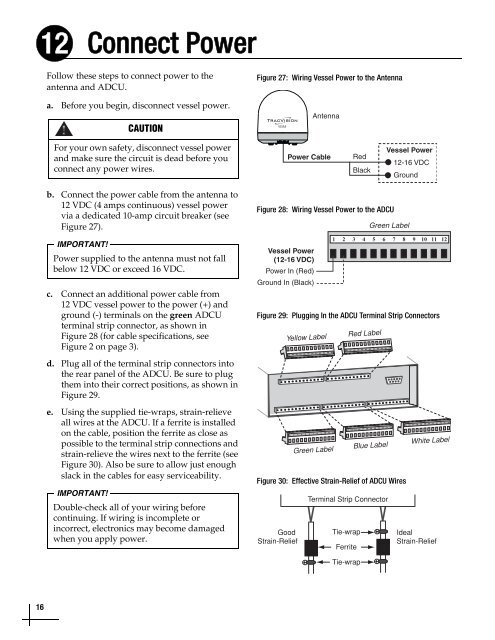
Follow these steps to connect power to the<br />
antenna and ADCU.<br />
a. Before you begin, disconnect vessel power.<br />
CAUTION<br />
Figure 27: Wiring Vessel Power to the Antenna<br />
Antenna<br />
For your own safety, disconnect vessel power<br />
and make sure the circuit is dead before you<br />
connect any power wires.<br />
Power Cable<br />
Red<br />
Black<br />
Vessel Power<br />
12-16 VDC<br />
Ground<br />
b. Connect the power cable from the antenna to<br />
12 VDC (4 amps continuous) vessel power<br />
via a dedicated 10-amp circuit breaker (see<br />
Figure 27).<br />
IMPORTANT!<br />
Power supplied to the antenna must not fall<br />
below 12 VDC or exceed 16 VDC.<br />
c. Connect an additional power cable from<br />
12 VDC vessel power to the power (+) and<br />
ground (-) terminals on the green ADCU<br />
terminal strip connector, as shown in<br />
Figure 28 (for cable specifications, see<br />
Figure 2 on page 3).<br />
d. Plug all of the terminal strip connectors into<br />
the rear panel of the ADCU. Be sure to plug<br />
them into their correct positions, as shown in<br />
Figure 29.<br />
e. Using the supplied tie-wraps, strain-relieve<br />
all wires at the ADCU. If a ferrite is installed<br />
on the cable, position the ferrite as close as<br />
possible to the terminal strip connections and<br />
strain-relieve the wires next to the ferrite (see<br />
Figure 30). Also be sure to allow just enough<br />
slack in the cables for easy serviceability.<br />
IMPORTANT!<br />
Double-check all of your wiring before<br />
continuing. If wiring is incomplete or<br />
incorrect, electronics may become damaged<br />
when you apply power.<br />
Figure 28: Wiring Vessel Power to the ADCU<br />
Vessel Power<br />
(12-16 VDC)<br />
Power In (Red)<br />
Ground In (Black)<br />
60 59 58 57 56 55 54 53 52 51 50 49<br />
1 2 3 4 5 6 7 8 9 10 11 12<br />
Green Label<br />
1 2 3 4 5 6 7 8 9 10 11 12<br />
Figure 29: Plugging In the ADCU Terminal Strip Connectors<br />
Good<br />
Strain-Relief<br />
Yellow Label<br />
Red Label<br />
48 47 46 45 44 43 42 41 40 39 38 37<br />
13 14 15 16 17 18 19 20 21 22 23 24<br />
25 26 27 28 29 30 31 32 33 34 35 36<br />
Green Label Blue Label White Label<br />
Figure 30: Effective Strain-Relief of ADCU Wires<br />
Terminal Strip Connector<br />
Tie-wrap<br />
Ferrite<br />
Ideal<br />
Strain-Relief<br />
Tie-wrap<br />
16